medical waste incinerators: background information for …infohouse.p2ric.org/ref/15/14349.pdf ·...
TRANSCRIPT
Uhited States Office of Au Quality EPA-453R-94-043a Envuoamental Rotection Planning and Standards July 1994 Agency Research Triangle Park. NC 2771 1
Medical Waste Incinerators - Background Information for Proposed Standards and Guidelines:
Process Description Report for New and Existing Facilities

I-\S€>\c: 0109
EPA-453IR-94-043a
Medical Waste Incinerators-Background Information for Proposed
Existing Facilities Standards and Guidelines: Process Description Report for New and
July 1994
U . S. Environmental Protection Agency Office of Air and Radiation
Office of Air Quality Planning and Standards Research Triangle Park, North Carolina

DISCLAIMER
This report is issued by the Emission Standards Division, Office of Air Quality Planning and Standards, U. S. Environmental Protection Agency. It presents technical data of interest to a limited number of readers. Mention of trade names and commercial products is not intended to constitute endorsement or recommendation for use. Copies of this report are available free of charge to Federal employees, current contractors and grantees, and nonprofit organizations--as supplies permit--from the Library Services Office (MD-35), U. S. Environmental Protection Agency, Research Triangle Park, North Carolina 27711 ([919] 541-2777) or, for a nominal fee, from the National Technical Information Service, 5285 Port Royal Road, Springfield, Virginia 22161 ([703] 487-4650).
iii

iv
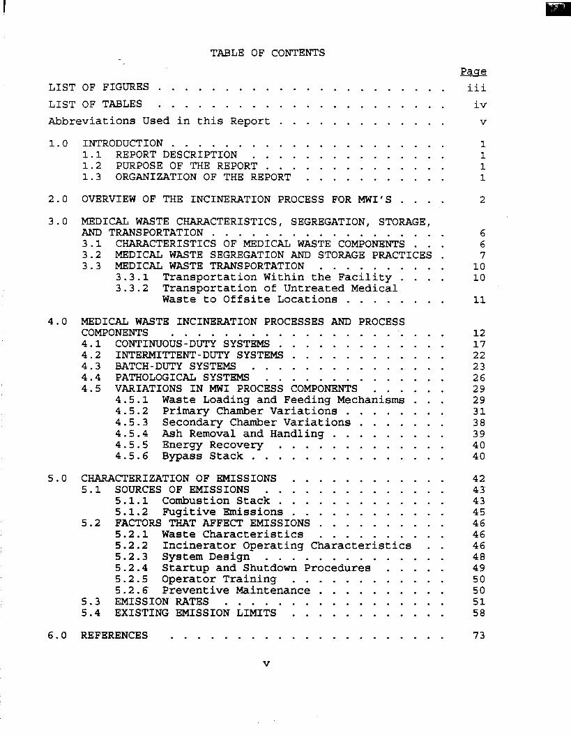
TABLE OF CONTENTS Pase
LIST OF FIGURES . . . . . . . . . . . . . . . . . . . . . . iii LIST OF TABLES . . . . . . . . . . . . . . . . . . . . . . iv Abbreviations Used in this Report . . . . . . . . . . . . . V
1.0 INTRODUCTION . . . . . . . . . . . . . . . . . . . . . 1 1.1 REPORT DESCRIPTION . . . . . . . . . . . . . . . 1 1.2 PURPOSE OF THE REPORT . . . . . . . . . . . . . . 1 1.3 ORGANIZATION OF THE REPORT . . . . . . . . . . . 1
2.0 OVERVIEW OF THE INCINERATION PROCESS FOR MWI’S . . . . 2
3.0 MEDICAL WASTE CHARACTERISTICS, SEGREGATION, STORAGE, AND TRANSPORTATION . . . . . . . . . . . . . . . . . . 6 3.1 CHARACTERISTICS OF MEDICAL WASTE COMPONENTS . . . 6 3.2 MEDICAL WASTE SEGREGATION AND STORAGE PRACTICES . 7 3.3 MEDICAL WASTE TRANSPORTATION . . . . . . . . . . 10
3.3.1 Transportation Within the Facility . . . . 10
Waste to Offsite Locations . . . . . . . . 11 3.3.2 Transportation of Untreated Medical
4.0 MEDICAL WASTE INCINERATION PROCESSES AND PROCESS COMPONENTS . . . . . . . . . . . . . . . . . . . . . 4.1 CONTINUOUS-DUTY SYSTEMS . . . . . . . . . . . . . 4.2 INTERMITTENT-DUTY SYSTEMS . . . . . . . . . . . . 4.3 BATCH-DUTY SYSTEMS . . . . . . . . . . . . . . . 4.4 PATHOLOGICAL SYSTEMS . . . . . . . . . . . . . . 4.5 VARIATIONS IN MWI PROCESS COMPONENTS . . . . . .
4.5.1 Waste Loading and Feeding Mechanisms . . . 4.5.2 Primary Chamber Variations . . . . . . . . 4.5.3 Secondary Chamber Variations . . . . . . . 4.5.4 Ash Removal and Handling . . . . . . . . . 4.5.5 Energy Recovery . . . . . . . . . . . . . 4.5.6 Bypass Stack . . . . . . . . . . . . . . .
5.0 CHARACTERIZATION OF EMISSIONS . . . . . . . . . . . . 5.1 SOURCES OF EMISSIONS . . . . . . . . . . . . . .
5.1.1 Combustion Stack . . . . . . . . . . . . . 5.1.2 Fugitive Emissions . . . . . . . . . . . .
5.2 FACTORS THAT AFFECT EMISSIONS . . . . . . . . . . 5.2.1 Waste Characteristics . . . . . . . . . . 5.2.2 Incinerator Operating Characteristics . . 5.2.3 System Design . . . . . . . . . . . . . . 5.2.4 Startup and Shutdown Procedures . . . . . 5.2.5 Operator Training . . . . . . . . . . . . 5.2.6 Preventive Maintenance . . . . . . . . . .
5.3 EMISSION RATES . . . . . . . . . . . . . . . . . 5.4 EXISTING EMISSION LIMITS . . . . . . . . . . . .
12 17 22 23 26 29 29 31 38 39 40 40
42 43 43 45 46 46 46 48 49 50 50 51 58
6.0 REFERENCES . . . . . . . . . . . . . . . . . . . . . 73
V

LIST OF FIGURES Page
Figure 1. Medical waste incineration process flow diagram . . . . . . . . . . . . . . . . . . . .
Figure 2. Schematic of a medical waste incinerator . . . Figure 3. Schematic of a continuous-duty medical waste
incinerator with stepped hearth and automatic ashremoval. . . . . . . . . . . . . . . . . .
Figure 4.
Figure 5.
Schematic of a rotary kiln medical waste incinerator . . . . . . . . . . . . . . . . . .
Schematic of an intermittent-duty medical waste incinerator . . . . . . . . . . . . . . .
Figure 6 . Schematic of a single batch medical waste incinerator . . . . . . . . . . . . . . . . . .
Figure 7. Retort hearth incinerator . . . . . . . . . . . Figure 8. Hopper/ram mechanical waste feed system . . . . Figure 9. Schematic of a single-hearth, intermittent-
duty incinerator equipped with an ash ram . . . Figure 10. Relationship between temperature and combustion
air levels . . . . . . . . . . . . . . . . . . Figure 11. MWI with a waste heat recovery boiler and
bypass stack . . . . . . . . . . . . . . . . .
13
18
20
21
24
25
28
30
3 3
3 6
41
vi
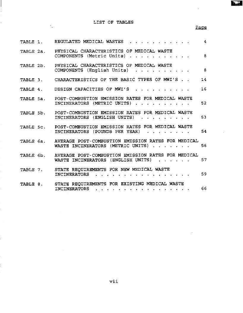
TABLE 1.
TABLE 2a.
TABLE 2b.
TABLE 3.
TABLE 4 .
TABLE 5a.
TABLE 5b.
TABLE 5c.
TABLE 6a.
TABLE 6b.
TABLE 7.
TABLE 8 .
LIST OF TABLES Pase
REGULATED MEDICAL WASTES . . . . . . . . . . . PHYSICAL CHARACTERISTICS OF MEDICAL WASTE COMPONENTS (Metric Units) . . . . . . . . . . . PHYSICAL CHARACTERISTICS OF MEDICAL WASTE COMPONENTS (English Units) . . . . . . . . . . CHARACTERISTICS OF THE BASIC TYPES OF MWI’S . . DESIGN CAPACITIES OF MWI’S . . . . . . . . . . POST-COMBUSTION EMISSION RATES FOR MEDICAL WASTE INCINERATORS (METRIC UNITS) . . . . . . . . . . POST-COMBUSTION EMISSION RATES FOR MEDICAL WASTE INCINERATORS (ENGLISH UNITS) . . . . . . . . . POST-COMBUSTION EMISSION RATES FOR MEDICAL WASTE INCINERATORS (POUNDS PER YEAR) . . . . . . . .
4
8
8
14
16
52
53
54
AVERAGE POST-COMBUSTION EMISSION RATES FOR MEDICAL WASTE INCINERATORS (METRIC UNITS) . . . . . . . 56
AVERAGE POST-COMBUSTION EMISSION RATES FOR MEDICAL WASTE INCINERATORS (ENGLISH UNITS) . . . . . . 57
STATE REQUIREMENTS FOR NEW MEDICAL WASTE INCINERATORS . . . . . . . . . . . . . . . . . 59
STATE REQUIREMENTS FOR EXISTING MEDICAL.WASTE INCINERATORS . . . . . . . . . . . . . . . . . 6 6
vii
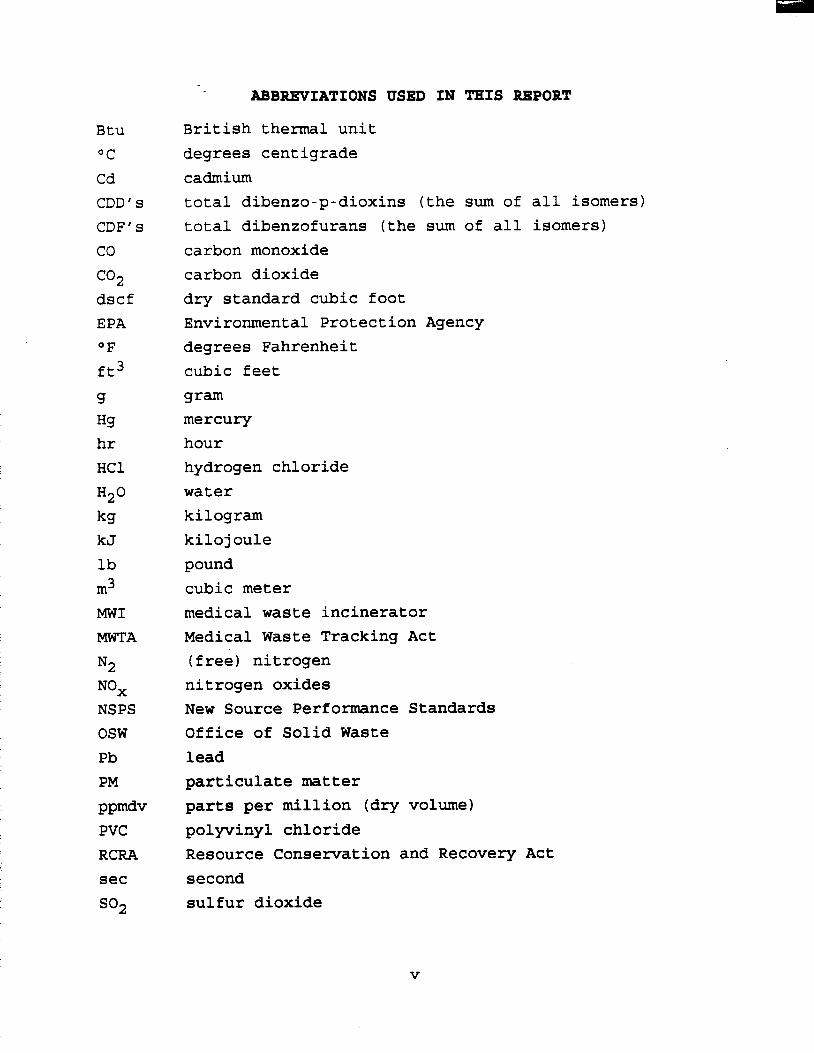
ABBREVIATIONS USED IN THIS REPORT
Btu OC Cd CDD’ s CDF’ s co co2 dscf EPA OF ft3
g Hg hr HC1
H2° kg kJ lb m3 MWI
MWTA
N2
NS PS osw Pb PM PPmdv PVC RCRA sec
so2
British thermal unit degrees centigrade cadmium total dibenzo-p-dioxins (the sum of all isomers) total dibenzofurans (the sum of all isomers) carbon monoxide carbon dioxide dry standard cubic foot Environmental Protection Agency degrees Fahrenheit cubic feet gram mercury hour hydrogen chloride water kilogram kilojoule pound cubic meter medical waste incinerator Medical Waste Tracking Act (free) nitrogen nitrogen oxides New Source Performance Standards Office of Solid Waste lead particulate matter parts per million (dry volume) polyvinyl chloride Resource Conservation and Recovery Act second sulfur dioxide
V
MEDICAL WASTE INCINERATOR FACILITY PROCESS DESCRIPTION
1.0 INTRODUCTION 1.1 REPORT DESCRIPTION
This report describes the medical waste incineration process starting from the point of generation of the waste and continuing through the handling and transportation of the waste, combustion process, and the disposal of the ash. is one of a series of reports written to provide background information on the medical waste' incineration industry, the process description, emissions, emission control technology, emission control costs, model plants, and environmental and energy impacts for the medical waste incineration process. 1.2 PURPOSE OF THE REPORT
This report is designed to provide an overview of the medical waste incineration process, describe the types of medical waste incinerators (MWI's) and their components, and to discuss the combustion process as it relates to MWI's. also intended to describe current practices associated with medical waste generation, segregation, handling, and transportation. Other specific purposes of the report include identifying and characterizing the pollutants, as well as describing the sources of emissions of these pollutants and the factors that affect emissions of specific pollutants. presents emission test data and existing State emission rate
the This document
The report is
The report
limitations. 1.3 ORGANIZATION OF THE REPORT
for MWI's and includes a description of the generic composition of medical waste, as well as a brief discussion of what happens during the combustion process. properties of medical waste and a description of how the waste is segregated, stored, and transported are presented in Section 3.0. The different types of MWI's and their associated components are described in Section 4 .0 .
Section 2.0 provides an overview of the incineration process
The physical and chemical
Included in this section is a
1
discussion of the variations in MWI components. The characterization of stack and fugitive emissions is presented in Section 5.0 . This section includes discussions of sources of emissions, factors that affect these emissions, and existing emission limits (based on existing State requirements for MWI's). 2.0 OVERVIEW O F THE INCINERATION PROCESS FOR MWI'S
Medical waste includes infectious and noninfectious wastes generated by facilities such as hospitals, clinics, doctors' and dentists' offices, nursing homes, veterinary establishments, medical and research laboratories, and funeral homes.
amended by the Medical Waste Tracking Act (MWTA), defines medical waste as I f . . . any solid waste which is generated in the diagnosis, treatment, or immunization of human beings or animals, in research pertaining thereto, or in production or testing of bio1ogicals.l' (llBiologicals" refers to preparations, such as vaccines, that are made from living organisms.) Medical waste is, in fact, a heterogeneous mixture of general refuse, laboratory and pharmaceutical chemicals and containers, and pathological waste. paper products, glass, food wastes, and metal containers. These materials may originate in administrative offices or cafeterias, as well as in laboratories, hospital wards, or operating rooms. Examples of laboratory and pharmaceutical chemical wastes include alcohols, disinfectants, antineoplastic (chemotherapeutic) agents, and materials containing heavy metals. Pathological wastes include tissues, organs, body parts, blood, and body fluids removed during surgery, autopsy, and biopsy.
agents and associated biologicals, human blood and blood products, pathological wastes, sharps, animal carcasses and bedding, and waste from patients with highly communicable diseases. The U. S. Environmental Protection Agency (EPA) Off ice of Solid Waste (OSW) uses the term "regulated medical waste" to denote the infectious component of medical waste. The categories of regulated medical waste, as defined by OSW, are presented in
The Resource Conservation and Recovery Act (RCRA) , 1976, as
General refuse includes plastic materials,
Medical waste includes cultures and stocks of infectious
2
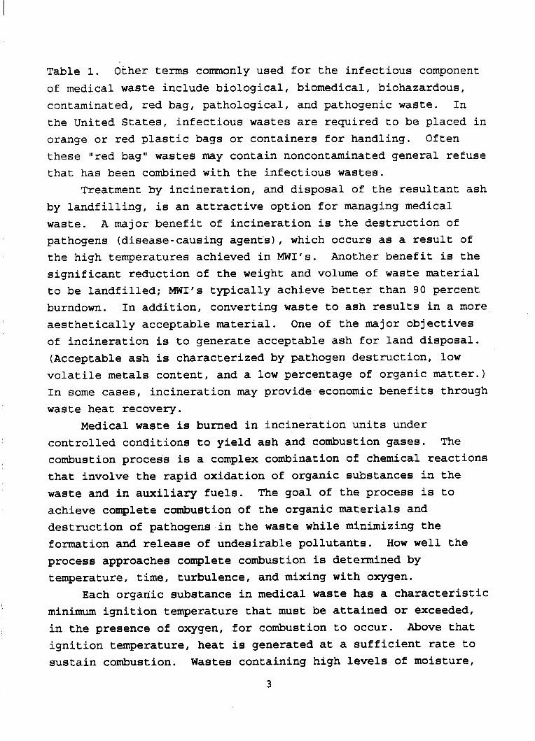
Table 1. Other terms commonly used for the infectious component of medical waste include biological, biomedical, biohazardous, contaminated, red bag, pathological, and pathogenic waste. In the United States, infectious wastes are required to be placed in orange or red plastic bags or containers for handling. Often these !Ired bag" wastes may contain noncontaminated general refuse that has been combined with the infectious wastes.
Treatment by incineration, and disposal of the resultant ash by landfilling, is an attractive option for managing medical waste. A major benefit of incineration is the destruction of pathogens (disease-causing agent's), which occurs as a result of the high temperatures achieved in MWI's. Another benefit is the significant reduction of the weight and volume of waste material to be landfilled; MWI's typically achieve better than 90 percent burndown. In addition, converting waste to ash results in a more aesthetically acceptable material. of incineration is to generate acceptable ash for land disposal. (Acceptable ash is characterized by pathogen destruction, low volatile metals content, and a low percentage of organic matter.) In some cases, incineration may provide economic benefits through waste heat recovery.
Medical waste is burned in incineration units under controlled conditions to yield ash and combustion gases. The combustion process is a complex combination of chemical reactions that involve the rapid oxidation of organic substances in the waste and in auxiliary fuels. achieve complete combustion of the organic materials and destruction of pathogens in the waste while minimizing the formation and release of undesirable pollutants. How well the process approaches complete combustion is determined by temperature, time, turbulence, and mixing with oxygen.
minimum ignition temperature that must be attained or exceeded, in the presence of oxygen, for combustion to occur. Above that ignition temperature, heat is generated at a sufficient rate to sustain combustion. Wastes containing high levels of moisture,
One of the major objectives
The goal of the process is to
Each organic substance in medical waste has a characteristic
3
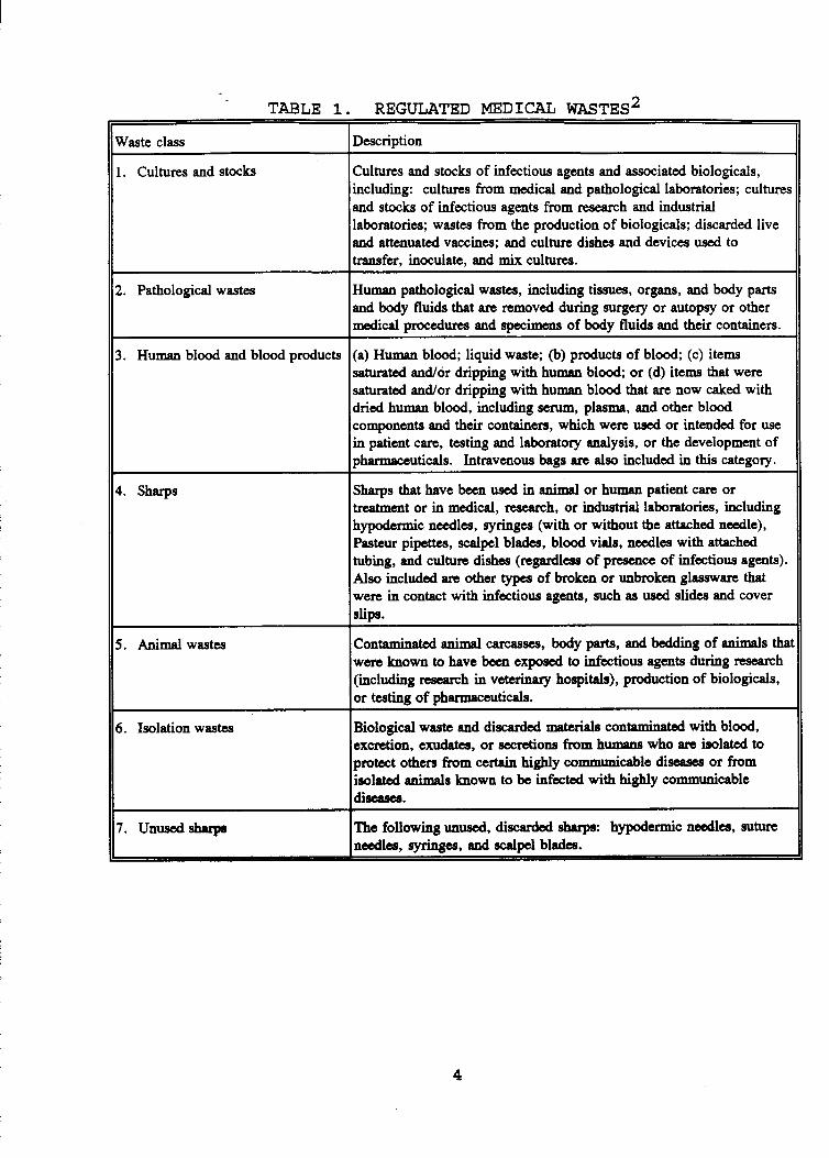
TABLE I. REGULATED MEDICAL WASTES~
Waste class
1. Cultures and stocks
1. Pathological wastes
3 . Human blood and blood products
1. Sharps
5. Animalwastes
5. Isolation wastes
7. Unusedshrupr
Description ~
Cultures and stocks of infectious agents and associated biologicals, including: cultures from medical and pathological laboratories; cultures and stocks of infectious agents from research and industrial laboratories; wastes from the production of biologicals; discarded live and attenuated vaccines; and culture dishes and devices used to transfer, inoculate, and mix cultures.
Human pathological wastes, including tissues, organs, and body parts and body fluids that arc removed during surgery or autopsy or other medical procedures and specimens of body fluids and their containers.
(a) Human blood; liquid waste; (b) products of blood; (c) items saturated and/or dripping with human blood; or (d) items that were saturated and/or dripping with human blood that are now caked with dried human blood, including serum, plasma, and other blood components and their containers, which were used or intended for use in patient care, testing and laboratory analysis, or the development of pharmaceuticals. Intravenous bags are also included in this category.
Sharps that have been used in animal or human patient care or treatment or in medical, nsearch, or industrial laboratories, including hypodermic needles, syringes (with or without the attached needle), Pasteur pipettes, scalpel blades, blood vials, needles with attached tubing, and culture dishes (regardleas of presence of infectious agents). Also included are other types of broken or unbroken glassware that were in contact with infectious agents, such as used slides and cover slips.
Contaminated animal arcassa, body parts, and bedding of animals tha1 w m known to have been exposed to infectious agents during nsearch (including nsearch in veterinary hospitals), production of biologicals, or testing of pharmaceuticals.
Biological waste and discarded materials contaminated with blood, excretion, e-, or secretions from humans who arc isolated to protect others from certain highly communicable diseases or from isolated animals known to be infected with highly communicable diseases.
The following unused, discarded sharps: hypodermic n d e s , suture needles. svrinnes, and scald blades.
4
however, require additional supplemental heat input. A waste constituent should reside in the high-temperature region of the MWI for a time period that exceeds the time required for it to completely combust. increases with increasing temperature, a shorter residence time is required for combustion at higher temperatures (assuming the presence of good combustion conditions). supplies and turbulence sufficient to promote the mixing of organic materials and oxygen are also essential for efficient combustion. result in emissions of incomplete combustion products. Turbulence within the primary chamber helps to break down the ash layer formed around burning particles of waste and expose the waste material to the high temperatures and combustion air. Bed turbulence is needed to maintain the combustion process and the elevated temperatures throughout the bed.
discussions focus on dual-chambered MWI's because of their prevalence in the industry. In these units, sequential combustion operations are carried out in two separate chambers. The primary chamber accepts the waste, and the combustion process is begun. Three processes occur in the primary chamber. First, the moisture in the waste is evaporated. Second, the volatile fraction of the waste is volatilized, and the volatilized gases are directed to the secondary chamber. Third, the nonvolatile combustible portion (fixed carbon) of the waste is burned. The typical operating temperature range for primary chambers is 650° to 76OOC (1200O to 1400°F), but the temperatures can range from 400° to 98OOC (750O to 1800OF). 3-5 Combustion gases containing the volatile combustible materials from the primary chamber are directed to the secondary chamber. Here the gases are burned with excess air, and at least one auxiliary fuel burner is used, as necessary, to maintain temperatures. According to most manufacturers, typical operating temperatures for secondary chambers range from 870° to llOO°C (1600O to 2000°F). The
Because the combustion reaction rate
Adequate oxygen
Inadequate mixing of combustible gases and air can
Throughout this report, unless otherwise indicated,
5
combustion gases from the secondary chamber are then vented through the stack to the atmosphere.
Medical waste incinerators have the potential to emit a variety of air pollutants. The pollutants from MWI's either exist in the waste feed material and are released unchanged during combustion, or they are generated as a result of the combustion process itself. These pollutants include particulate matter (PM); toxic metals; toxic organics; carbon monoxide (CO); and the acid gases hydrogen chloride (HCl), sulfur dioxide ( S O 2 ) ,
and nitrogen oxides (NOx). In addition to emissions of pollutants through the combustion air stack, there is the potential for fugitive emissions in the medical waste incineration process. These emissions occur while charging the waste, handling the ash, and handling and transporting the catch or residue from air pollution control devices (e.g., fabric filters). 3.0 MEDICAL WASTE CHARACTERISTICS, SEGREGATION, STORAGE, AND
TRANSPORTATION The characteristics of medical waste, in tems of its
physical and chemical properties, are described in Section 3.1. Section 3.2 describes current medical waste segregation and storage practices. Section 3.3.
Transportation practices are discussed in
3.1 CHARACTERISTICS OF MEDICAL WASTE COMPONENTS Medical waste is characteristically heterogeneous,
consisting of items composed of many different materials. The composition of the wastes depends on the type of generator and the source of the waste within the generator facility. Activities and procedures within the facility can vary significantly from day to day, making it difficult to predict the composition of the waste. Therefore, no data are available from which a representative characterization of medical waste can be formulated, and only the gomonentg of the waste can be characterized. The chemical and physical properties of the components of wastes treated in MI'S vary considerably--not only from charge to charge, but within each charge to the incinerator.
6
The waste characteristics are important because they may affect combustion efficiency and emission characteristics. A study of hospitals in Ontario provided information on the heating value, bulk density, and moisture content of different medical waste materials. The results from this study are presented in Tables 2a (metric units) and 2b (English units) .3 these tables, the heating values (as fired) range from about 2,330 kilojoules per gram (kJ/g) (1,000 British thermal units per pound [Btu/lb]) for high-moisture, low-heat-content anatomical waste to 46,500 kJ/g (20,000 Btu/lb) for low-moisture, high-heat- content plastics such as polyethylene. from 80 kilograms per cubic meter (kg/m3) foot [lb/ft3]) to 8,000 kg/m3 (500 lb/ft3). Moisture contents varied from zero to 100 percent.
the metals and plastics, are also of concern because of their impact on air pollutant emissions. that vaporize at the hearth temperatures encountered in the primary combustion chamber may be emitted as metal oxides. Halogenated plastics such as polyvinyl chloride (PVC) produce acid gases (e.g., HC1). The presence of the chlorinated wastes may also contribute to the formation of toxic organic pollutants such as dioxins (CDD's) and furans (CDF's). 3.2 MEDICAL WASTE SEGREGATION AND STORAGE PRACTICES
As shown in
Bulk densities ranged (5 pounds per cubic
The chemical composition of the medical wastes, particularly
Metals and metal compounds
The degree to which medical waste is segregated is typically a function of the size of the generator and the economics of disposal options. If a large incinerator is available or if unsegregated wastes may be hauled to a local landfill, a generator may combine most or all medical wastes in preparation for disposal. However, a generator might tend to segregate medical waste more carefully in cases where only a small incinerator is available or when the waste hauling charges are significant, and the added costs of special handling would apply to the noninfectious component of medical waste as well.
to exclude from the medical wastes certain materials that may During the segregation process, efforts are generally made
7
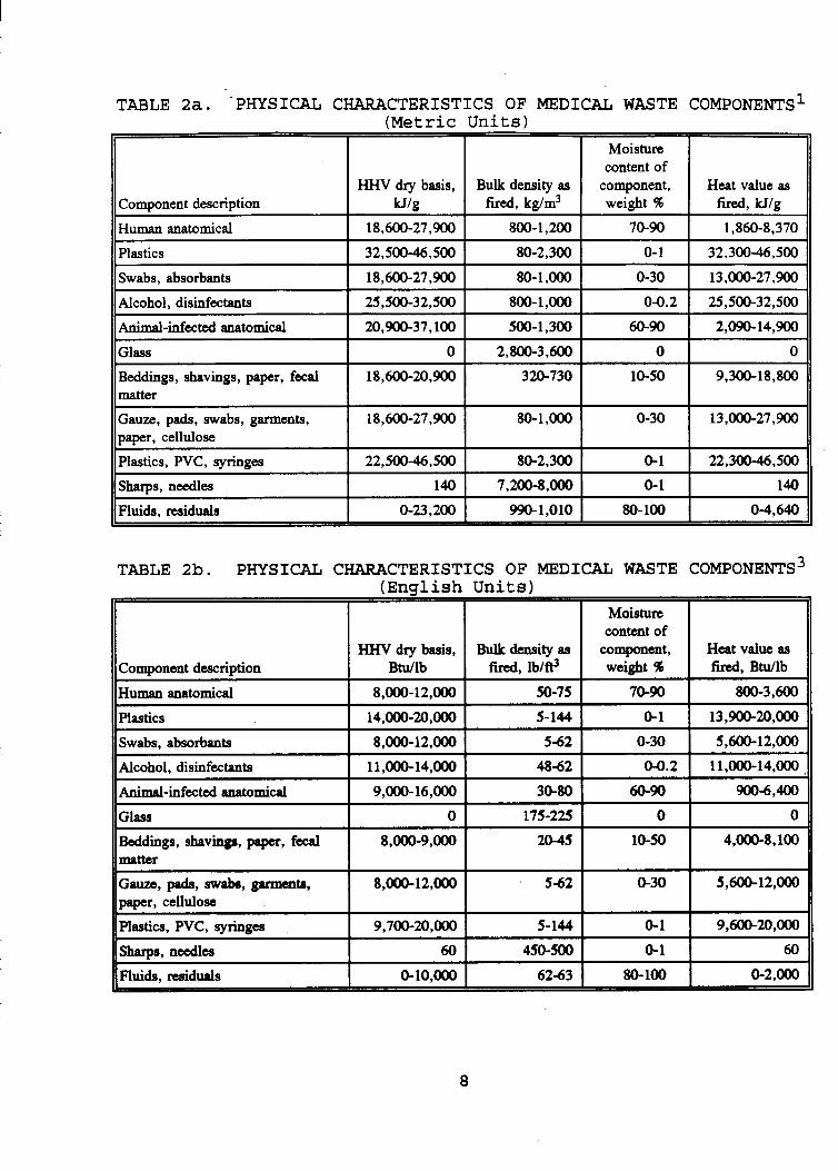
TABLE 2a. -PHYSICAL CHARACTERISTICS OF MEDICAL WASTE COMPONENTS~ (Metric Units)
18,600-27,900
25,500-32,500
Component description
Human anatomical
80- 1 ,OOO 0-30 13 ,OOO-27,9OO
800-1,OOO 04.2 25,500-32,500
Plastics
0
18,600-20,900
18,600-27,900
22,500-46.500
Swabs. absorbants
2,800-3,600 0 0
320-730 10-50 9,300- 18,800
80-1,OOO 0-30 13,OOO-27,900
80-2,300 0-1 22,30046,500
Alcohol, disinfectants
- 140 7,200-8,000
0-23.200 990-1.010
Animal-infected anatomical
0- 1 140
80-100 04,640
Glass
Beddings, shavings, paper, fecal matter
Gauze, pads, mh, garmenta, paper, cellulose Plastics, PVC, syringes
sharps, needles
Fluids, miduals
Beddings, shavings, paper, fecal matter
8,OoO-9,OOO 20-45 10-50 4,000-8,100
8,000-12,000 5-62 0-30 5,600-12,ooO
9,700-20,m 5-144 0-1 9,600-20,OOO
60 450-500 0-1 60
0-10,m 62-63 80-100 0-2 ,m
Gauze, pads, swabs, garments, paper, cellulose
Plastics, PVC, syringes
Sharps, needles
Fluids. residuals
fired, kg/m3
18,600-27,900 800-1,200
Moisture content of
l component, weight %
70-90
Heat value as fired, Utg
1, "3 ,370
~ ~~
~ 20,900-37.100 1 500-1,300 I 60-90 I 2,090-14,900
TABLE 2b. PHYSICAL CHARACTERISTICS OF MEDICAL WASTE COMPONENTS3 (English Units)
8
create special problems in the combustion process, adversely impact the composition of the effluents or residues from the process, or unnecessarily contribute to the volume of wastes to be incinerated. For example, the presence of batteries or radiological materials in the waste feed may account for high concentrations of heavy metals (e.g., lead, mercury, and cadmium) in incinerator ash, and so these items are often segregated from the wastes to be combusted. While paper plates, polystyrene cups, and other Ildry" hospital cafeteria wastes may be included with medical wastes, cafeteria food wastes are often excluded from the medical wastes to be incinerated because of their high moisture content. Metal cans from cafeterias also are generally excluded. Large stacks of computer paper are usually segregated from medical wastes unless they are shredded prior to incineration. rather than incinerated.
other wastes are appropriately excluded from medical waste intended for incineration. While the Nuclear Regulatory Commission (NRC) permits the incineration of certain wastes containing low-level radioactive materials (e.g., scintillation vials, research animal carcasses, and certain chemotherapy wastes with radioactive concentrations below a specified level), special permits are required to treat other radioactive wastes. cases, it is inappropriate to use MWI's to dispose of some radioactive wastes and certain hazardous wastes regulated under RCRA. However, there are a few incineration facilities designed primarily as M W I f s that have obtained permits to treat wastes regulated under RCRA.
frequently used to help segregate and identify medical waste. Most often, red or red-orange bags are used for infectious wastes, and these wastes are usually double-bagged. For aesthetic reasons, opaque bags are generally used for certain types of wastes (e.g., pathological). Other colored containers may be used based on the protocol of the particular generator.
Bulky cardboard is often compacted and recycled
In addition to the above examples of waste segregation,
In most
Color-coded bags (usually polyethylene) and containers are
9
For example; generators might use blue bags for body fluid wastes, orange bags for chemotherapy wastes, and brown bags for general waste. Plastic bags containing medical wastes are sometimes placed in plastic-lined, corrugated cartons or fiber drums, which are then appropriately labelled. Sharps, such as needles, scalpels, and pipettes, are commonly placed in rigid, colored, puncture-proof plastic containers. Capped or tightly stoppered bottles or flasks may be used for liquid wastes, as may tanks. Use of the biological hazard symbol on appropriate packaging is recommended. used, the integrity of the packaging must be preserved throughout handling, storage, and transportation.
offsite disposal is typically kept to a minimum. Some States regulate storage times. For example, Massachusetts allows infectious waste to be stored for 24 hours at room temperature ( 1 8 O to 25OC [64O to 77OFI) or for 72 hours at refrigerated temperatures (lo to 7OC [34O to 45OFI) Wastes stored without refrigeration for several days are prone to increased rates of microbial growth and putrefaction. Ideally, wastes are stored in areas with refrigeration and provisions for regular disinfection to avoid the spread of disease by rodents and vermin. areas typically are secured from public access. These areas generally display the biological hazard symbol. 3.3 MEDICAL WASTE TRANSPORTATION 3.3.1 Transnortation Within the Facilitv
facility using chutes and wheeled containers. (Chutes are not recommended for transporting infectious wastes.) Plastic bags and other containers described in the previous section may be placed in rigid, leakproof containers with wheels to be transported to storage or treatment areas. When mechanical loading devices are used, care must be taken to avoid rupturing the packaged wastes.
Regardless of the type of containers
The storage of medical wastes prior to onsite treatment or
Storage
Medical wastes are transported within the generating
10
3.3.2 TransDortation of Untreated Medical Waste to Of fsite Locations
Medical waste intended for offsite treatment generally is transported in closed and leakproof dumpsters or trucks to prevent the waste from scattering, spilling, and leaking during transport. containment system, medical wastes typically are placed in rigid or semi-rigid, leakproof containers before being loaded into a truck.
packaging requirements are generally imposed by State or Federal regulations. waste be placed in double (plastic) bags, with each bag tied or taped and the bags placed in plastic-lined, rigid, corrugated cartons or fiber drums, which are then sealed or taped. The containers are generally required to be marked with the universal biohazard symbol or the words "infectious waste," and if chemotherapy wastes are included, the containers must be so marked. Other labeling of the containers, as well as manifesting procedures, must conform with the statutory requirements of the generator's State. Classifications of medical, and specifically infectious, wastes vary among the States. Drivers or warehousemen at the disposal site may inspect each shipment of medical waste (e.g., for structural integrity of the containers or for the presence of radiation hazards). may reserve the right to refuse any ''off-spec" packages.
Carts and other reusable transport mechanisms should be disinfected frequently and, when used to transport infectious wastes, should not be used to transport other materials prior to decontamination.
offsite facility be required, procedures are the same as those discussed in Section 3.2.
As discussed in Section 3.2, the degree of segregation of medical wastes (i.e., infectious vs. noninfectious or regulated vs. nonregulated) is likely to be greater when the waste is to be
Because the truck is not considered to be a rigid
When medical waste is transported offsite, specific
These regulations typically require that infectious
The disposal company
Should storage of medical waste during transport or at the
11
shipped offsite for treatment. Therefore, the characteristics of the waste may be considerably different from those of medical waste treated onsite. Because of the requirements of the disposal facility and the special handling costs and regulatory requirements associated with hauling medical wastes, waste shipped offsite is more likely to be composed primarily of materials defined as infectious. 4.0 MEDICAL WASTE INCINERATION PROCESSES AND PROCESS COMPONENTS
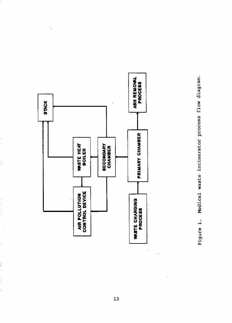
The medical waste incineration process can be described in terms of the following steps: waste charging, primary chamber combustion, solids movement though the primary chamber, secondary chamber combustion, combustion gas handling, and ash removal. Figure 1 is a process flow diagram that illustrates how these steps relate to each other in the incineration system.
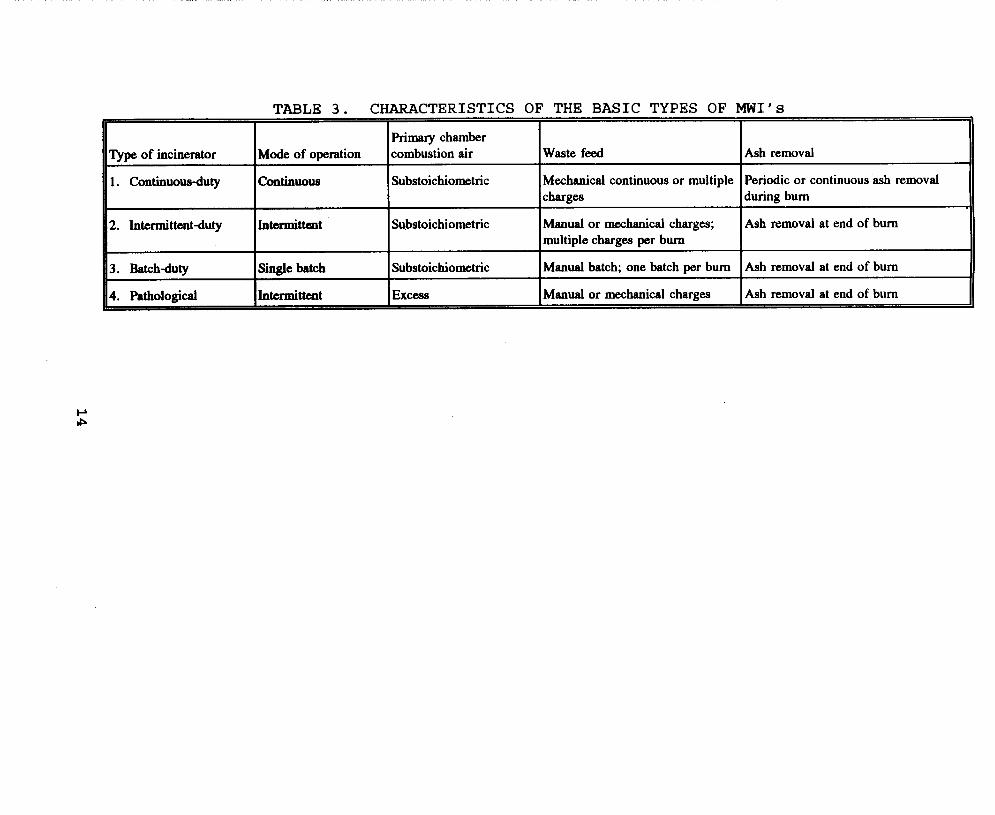
The important factors that help to characterize an MWI system and its operation are the mode of operation, the method of waste feed charging, the method of ash removal, and the air distribution to the combustion chambers. The basic types of MWI's can be classified by mode of operation as continuous-duty, intermittent-duty, and batch-duty systems. All MWI's, regardless of the type of waste burned, fit into one of these MWI types. However, MWI's burning pathological waste, while they fall under the intermittent-duty category, operate significantly differently and have significantly different emission characteristics from other intermittent-duty MWI's. Therefore, pathological MWI's are treated as a separate subcategory of MWI's. systems, sequential combustion operations typically are carried out in two separate chambers (primary and secondary). Table 3
characterizes the major types of MWI's with respect to these factors.
manually or mechanically. Typically, manual waste feed charging is used on batch-duty units and those intermittent-duty MWI's with capacities less than 180 kilograms per hour (kg/hr) (400 pounds per hour [lb/hr]). Intermittent-duty units larger than 180 kg/hr (400 lb/hr) and continuous-duty MWI's generally
In each of these
Waste charging to the primary chamber is accomplished either
12
L
tn Id -d a
w m m a, U 0 k a k 0 L,
m Id 3 d Id U
13
Type of incinerator
1. Continuowduty
2. Intermittentduty
3. Batchduty
Mode of operation
Continuous
Inttrmittalt
S i l e batch I 'htcd#ent ,
TABLE 3. CHARACTERISTICS OF THE BASIC TYPES OF MI'S I I 11
primary chamber combustion air Waste feed Ash removal
Substoichiometric Mechanical continuous or multiple Periodic or continuous ash removal charges during bum
Manual or mechanical charges; multiple charges per bum
Manual batch; one batch per bum
Manual or mechanical charges
Substoichiometric Ash removal at end of bum
Substoichiometric
Excess
Ash removal at end of bum
Ash removal at end of bum
have a mechanical waste feed charging system. units have a means of moving the waste/ash bed from the charging end to the ash-discharge end, while intermittent- and batch-duty units utilizing manual charging have no means of solids transfer in the primary chamber.
Ash is removed either periodically or continuously, depending upon the operating mode of the MWI (see Table 3). Continuous ash removal, used for continuous-duty MWI’s, takes place while the incinerator is operating. is performed either manually or mechanically (typically on the morning after a burn) in units without continuous ash removal systems.
of air needed to provide exactly the theoretical amount of oxygen needed for the carbon and hydrogen in the waste to completely combust. For MWI‘s, air distribution can be classified based on whether the primary chamber operates under starved (substoichiometric) or excess-air (an amount above stoichiometric) conditions. In most MWI’s, the combustion process in the primary chamber proceeds in a substoichiometric oxygen atmosphere. However, pathological systems operate with excess air in the primary chamber.
With the exception of pathological MWI’s, the continuous- duty, intermittent-duty, and batch-duty MWI’s are designed to burn general medical waste (including pathological waste) that typically has a heating value of 1.98 x lo7 Joule/kg (8,500 Btu/lb). Pathological MWI’s are designed to burn only pathological waste, typically having a heating value of 2.3 x lo6 Joule/kg (1,000 Btu/lb) . However, there is a pathological Itdual mode” system that operates under substoichiometric conditions when burning nonpathological wastes and under excess- air conditions when treating only pathological wastes.
The design capacities of MWI’s are presented in Table 4 .
These capacities range from 20 kg/hr (50 lb/hr) for intermittent- duty, pathological and nonpathological systems to 2,830 kg/hr (6,250 lb/hr) for continuous-duty systems. For batch units, the
Continuous-duty
Periodic ash removal
The stoichiometric amount of combustion air is the quantity
15
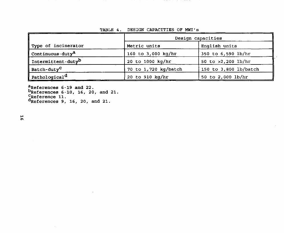
TABLE 4. DESIGN CAPACITIES OF MWI’s
Type of incinerator
Continuous-dutya
Design capacities
Metric units English units
160 to 3,000 kq/hr 350 to 6,590 lb/hr
Intermit tent -dutyb
Batch - duty 1 Patholosicald I20 to 910 kq/hr I 50 to 2,000 lb/hr
20 to 1000 kg/hr 50 to >2,200 lb/hr
70 to 1,720 kg/batch 150 to 3,800 lb/batch
aReferences 6-19 and 22. bReferenCe8 6-10, 16, 20, and 21. ‘Reference 11. dReferences 9, 16, 20, and 21.
capacities range from 70 kg/batch (150 lb/batch) to 1,720 kg/batch (3,800 lb/batch) .
in their process components, are discussed in greater detail in the following sections. Sections 4.1, 4.2, and 4.3 describe continuous-duty, intermittent-duty, and batch-duty MWI’s, respectively, with respect to the combustion of general medical waste. Section 4.4 describes pathological MWI’s (also intermittent-duty MWI’s) with respect to the combustion of pathological waste and also includes a description of retort hearth MWI‘s. Section 4.5 describes the variations in process components among the basic MWI types.
Each of the basic types of MWI‘s, along with the variations
4.1 CONTINUOUS-DUTY SYSTEMS This section first provides a brief overview of the general
medical waste combustion process occurring in the MWI, describes the flow of combustion air and exhaust gases through the system, and discusses the control of combustion air to the primary and secondary chambers. Secondly, this section describes the unique features of continuous-duty systems.
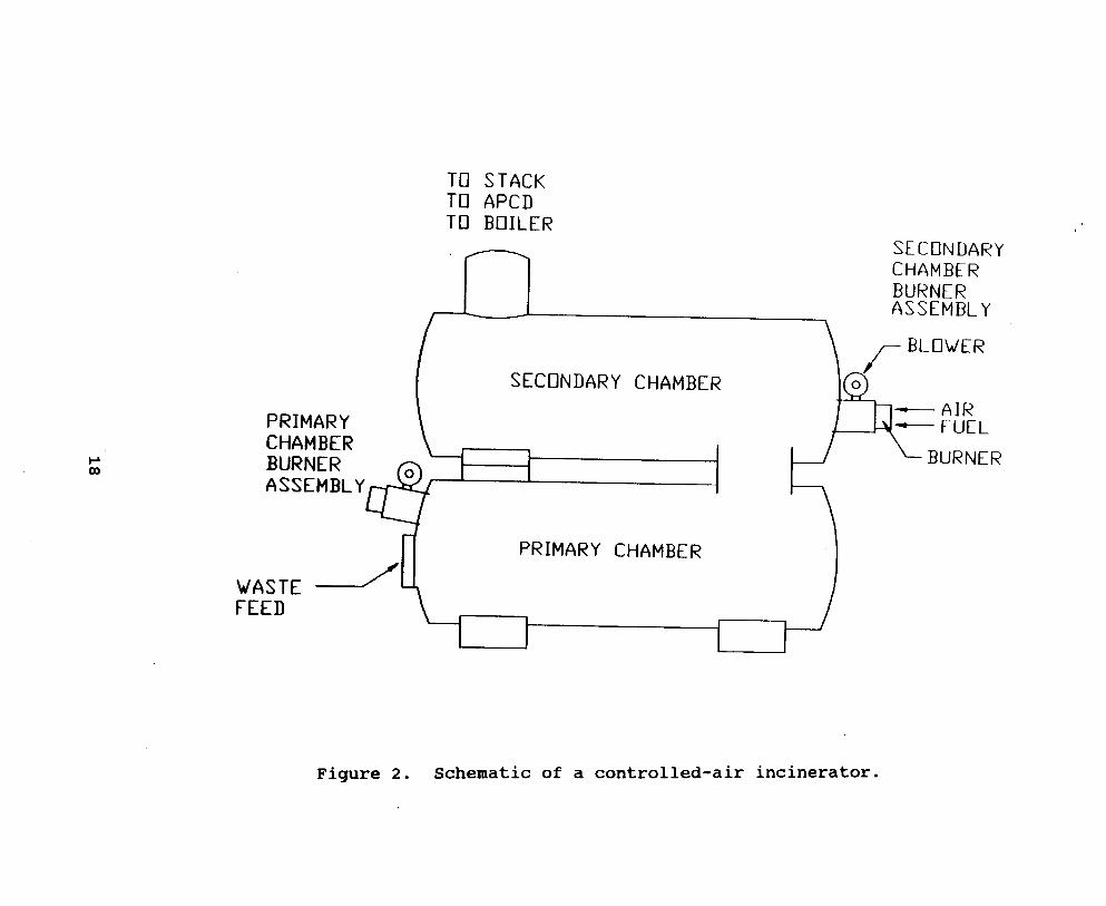
The waste enters the primary chamber, where it is ignited. The moisture in the waste is evaporated, the volatile fraction is vaporized, and the fixed carbon remaining in the waste is combusted. flow to the primary chamber may be set at a fixed rate or it may be varied based on primary chamber exit gas temperature to maintain a substoichiometric oxygen condition. containing the volatile combustible materials from the primary chamber are directed to the secondary chamber. chamber, the combustion air is regulated to provide an excess-air combustion condition and is introduced to the chamber in a manner that produces turbulence and promotes mixing of the combustion gases and combustion air. Combustion air is regulated using modulating combustion air dampers or fans that are activated based on the secondary chamber exit gas temperatures. the combustion gases under conditions of high temperature, excess oxygen, and turbulence promotes complete combustion.
Figure 2 is a schematic of an MWI.
The combustion air
The gases
In the secondary
Burning
17
TO STACK TO APCD TO BOILER
SECONDARY CHAMBER BURNER ASSEMBLY
SECONDARY CHAMBER
PRIMARY CHAMBER
I
Figure 2. Schematic of a controlled-air incinerator.
Limiting air to substoichiometric conditions in the primary chamber prevents rapid combustion and favors the quiescent conditions that minimize entrainment of PM in the combustion gases. A l s o , control of the distribution and amount of combustion air allows the primary chamber temperatures to be maintained below the melting and fusion points of most metals, glass, and other noncombustibles, thereby minimizing slagging and clinker formation. On the other hand, sufficiently high temperatures can be maintained in a turbulent condition with excess oxygen in the secondary chamber to ensure complete combustion of the combustion gases, while at the same time avoiding temperatures that are hot enough to cause refractory damage.
The continuous-duty MWI has an operating cycle that can accommodate waste charging for an unrestricted length of time because ash is automatically discharged from the incinerator on a continuous basis. The unit can be automatically charged with relatively small charges at frequent, regulated time intervals. Available information indicates that nearly all of these units are used by commercial facilities, hospitals, and laboratories. 6-15 medical waste incineration requirements are continuous and do not allow for periodic shutdown of the units for ash removal.
either a fixed-hearth, a rotary kiln, or a moving hearth such as a Pulse Hearthm or a stoker. Currently, fixed-hearth systems are significantly more prevalent than the other types. their size and because of the need to move waste through the system effectively, most continuous-duty, fixed-hearth MWI's utilize stepped hearths. stepped-hearth MWI with internal ash transfer rams.
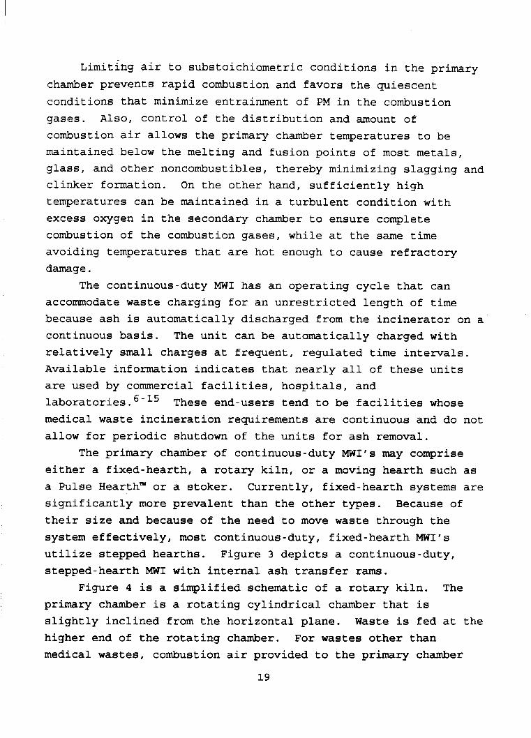
Figure 4 is a simplified schematic of a rotary kiln. primary chamber is a rotating cylindrical chamber that is slightly inclined from the horizontal plane. higher end of the rotating chamber. medical wastes, combustion air provided to the primary chamber
These end-users tend to be facilities whose
The primary chamber of continuous-duty MWI's may comprise
Because of
Figure 3 depicts a continuous-duty,
The
Waste is fed at the For wastes other than
19

TO STACK TO APCD TO BOILER
SECONDARY CHAMBER BURNER ASSEMBLY
SECONDARY CHAMBER
PRIMARY CHAMBER
I -_______1
ASH TRANSFER RAM -- ASH DISHCHARGE RAM 4
ASH QUENCH
Figure 3. Schematic of a continuous-duty medical waste incinerator with stepped hearth and automatic ash removal.
I 0 z w 2 Q
I Ln a
I I
I rl rd u
w 0
21

typically creates an excess-air atmosphere. However, a major manufacturer of rotary kilns used as MWI's reports that the airflow to the primary chamber in these kilns is substoichiometric. 22 reduces kiln size and decreases auxiliary fuel usage in the secondary chamber. Inside the rotating chamber, moisture and volatiles are vaporized from the waste, and the waste is ignited. As the chamber rotates, the solids tumble within the chamber and slowly move down the incline toward the discharge end. turbulence of the waste provides exposure of the solids to the combustion air. Combustion of the solids occurs within the rotating chamber, and the residue ash is discharged from the end of the kiln into an ash removal system. The volatile gases pass from the primary chamber into the secondary chamber, where combustion of the gases is completed.
Because the waste continuously moves down the length of the rotating chamber and ash is removed continuously, the incineration system is designed to operate with continuous waste feed input. Available information indicates that relatively few rotary kilns are being used as MWI's, and most of these are used
Operating the kiln under these conditions
The
at hospitals. 10, 16-19
Pulse Hearth- and stoker systems are used to a lesser extent than fixed-hearth and rotary kiln MWI's and are described in Section 4 . 5 . 2 . 2 .
4.2 INTERMITTENT-DUTY SYSTEMS An intermittent-duty MWI typically has an operating cycle o f
less than 24 hours. The unit is designed to accept waste charges for durations of 8 to 16 hours, depending upon its size. Once ash builds up to a level that interferes with noma1 charging of the unit, the unit must be shut down and the ash removed. The intermittent charging procedure allows the daily charge to the MWI to be divided into a number of smaller charges that can be introduced over the combustion cycle. every 6 to 15 minutes. operating cycle for an intermittent-duty MWI.
Waste is generally charged The following is a typical daily
22
1. 15 to 30 minutes 2. Preheat of incinerator 30 to 60 minutes 3. Charging of waste Varies (up to
16 hours) 4. Burndown 2 to 4 hours 5. Cooldown 5 to 8 hours
Cleanout of ash from previous day
The burndown step indicates the period of time in the cycle during which no additional waste is charged to the incinerator, and the solid phase combustion of the waste bed is taking place in the primary chamber. The cooldown step, the period during which the MWI is allowed to cool, occurs at the end of the operating cycle, after the burndown step and may or may not use forced air.
A schematic of an intermittent-duty MWI is presented in Figure 5. This unit has a vertically oriented primary chamber followed by a horizontal secondary chamber. Intermittent-duty MWI's are used in hospitals, laboratories and research facilities, nursing homes, and veterinaries. 6-10,16,20,21
4.3 BATCH-DUTY SYSTEMS In this type of system, the incinerator is charged with a
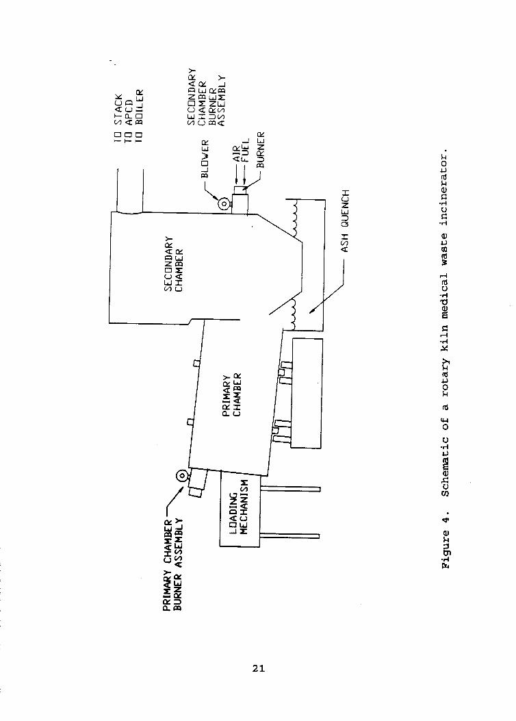
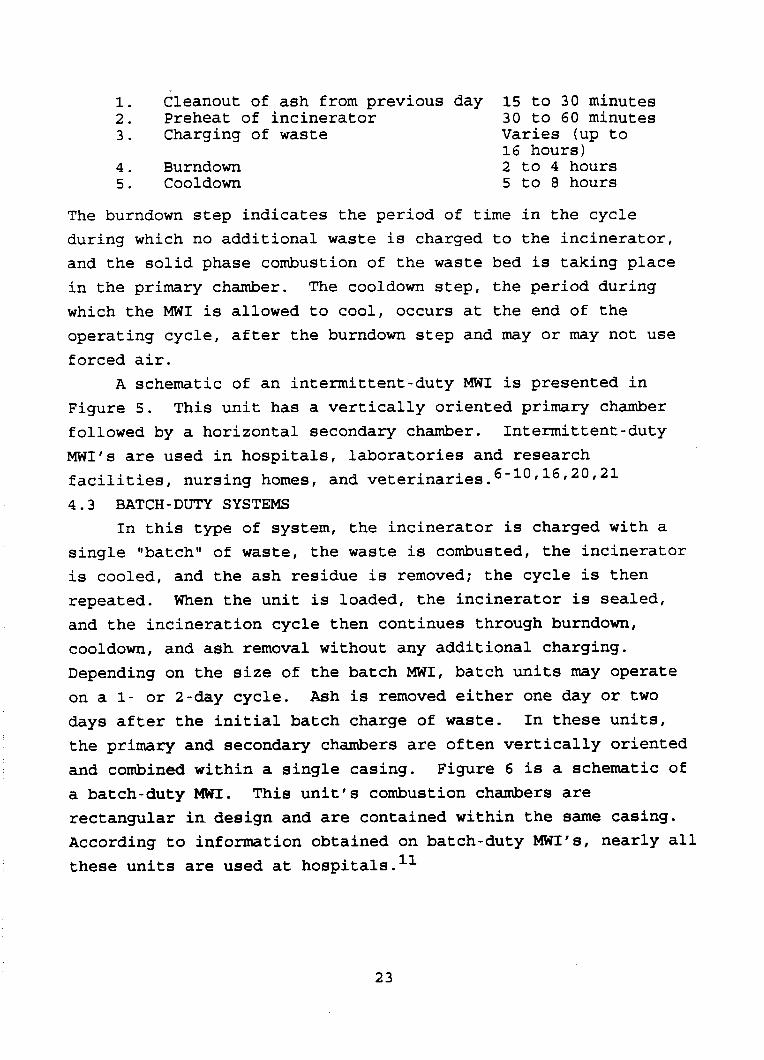
single llbatchll of waste, the waste is combusted, the incinerator is cooled, and the ash residue is removed; the cycle is then repeated. When the unit is loaded, the incinerator is sealed, and the incineration cycle then continues through burndown, cooldown, and ash removal without any additional charging. Depending on the size of the batch MWI, batch units may operate on a 1- or 2-day cycle. Ash is removed either one day or two days after the initial batch charge of waste. the primary and secondary chambers are often vertically oriented and combined within a single casing. Figure 6 is a schematic of a batch-duty MWI. This unit's combustion chambers are rectangular in design and are contained within the same casing. According to information obtained on batch-duty MI'S, nearly all these units are used at hospitals.
In these units,
11
23

7 FEED DOOR
Figure 5. Schematic of an intermittent-duty medical waste incinerator.
A S H R E M O V A L DOOR PRIMARY CHAMBER
WASTE CHARGE DOOR
Figure 6. Schematic of a single batch-duty medical waste incinerator.
PRIMARY CHAMBER
4 . 4 PATHOLOGICAL SYSTEMS Incinerators that burn only pathological wastes operate
under excess-air conditions. Excess-air systems are better suited to the incineration of pathological wastes than red bag wastes because the volatile content of pathological waste is low, and, in general, the waste composition is not highly variable. The primary burner provides most of the heat input, and the incinerator operates in a steady, constant mode with a regular, consistent combustion air input and excess-air level.
There is a "dual mode" system that is designed to burn either pathological or nonpathological (general medical) wastes. The dual mode feature is achieved through the use of a switch that controls the operation of the primary chamber burners and the combustion air blowers. In the pathological mode, the primary chamber burner (9 ) cycle (s) on and off more frequently (or remains on) to accommodate the combustion requirements of the pathological wastes with their lower Btu values. Because of the high moisture content of the pathological wastes, combustion cannot be sustained without using auxiliary fuel. The air supply required to operate the burner and the relatively small amount of combustible gases generated from the waste result in an excess- air condition in the primary chamber. in the nonpathological mode, the primary burner is turned off because the waste provides its own fuel. In this mode the underfire combustion air levels are set to maintain a
23 substoichiometric condition in the primary chamber.
duty operation--i.e., these units generally do not have automatic, continuous ash removal systems. Consequently, the incinerator must be shut down at routine intervals (e.g., daily) for ash removal. Pathological systems are used at hospitals, nursing homes, research laboratories, and veterinaries.
waste in the past is the retort hearth system. being used to a limited extent only and can be characterized as
When the unit is operated
Pathological MWI's are typically designed for intermittent-
16,20,21
A traditional design that has been used to burn medical This system is
26
an older, existing hospital incinerator. The principal design configuration for the unit is shown in Figure 7.
The system operates under excess-air conditions in the primary and secondary chambers. Combustion of the waste begins in the primary chamber. The waste is dried, ignited, and combusted by heat provided by a primary chamber burner, as well as by hot chamber walls and hearth that are heated by the flue gases. The combustion gases containing the volatiles pass out of the primary chamber through a flame port into a mixing chamber and then pass into the secondary chamber. Secondary air is added through the flame port and mixed with the combustion gas in the mixing chamber. chamber to maintain adequate temperatures for complete combustion as the gases pass into and through the secondary combustion chamber. Waste is fed manually or mechanically with single or multiple batches per burn. Ash is removed on a batch basis at the end of the burn. The retort design accommodates capacities under 230 kg/hr (500 lb/hr) . 2 4
wastes. There are drawbacks to using these units to incinerate general medical wastes. air predominantly to promote surface combustion. overfire air in the primary chamber results in entrainment of fly ash, which can cause excessive PM emissions. Also, because the primary chamber is in an excess-air mode and these older units lack controls, the combustion air levels and the combustion rate within the primary chamber are not easily controlled. Consequently, there may be no assurance of complete combustion when waste composition and volatile content of the waste fluctuate over a wide range. does not exhibit the variation in composition found in other medical wastes, and it has a lower volatile content, these units are better suited to incinerate pathological wastes than general hospital wastes.
A secondary burner is provided in the mixing
The retort hearth system is best suited to burn pathological
Retort units employ overfire combustion This excess,
Because true pathological waste
2 7
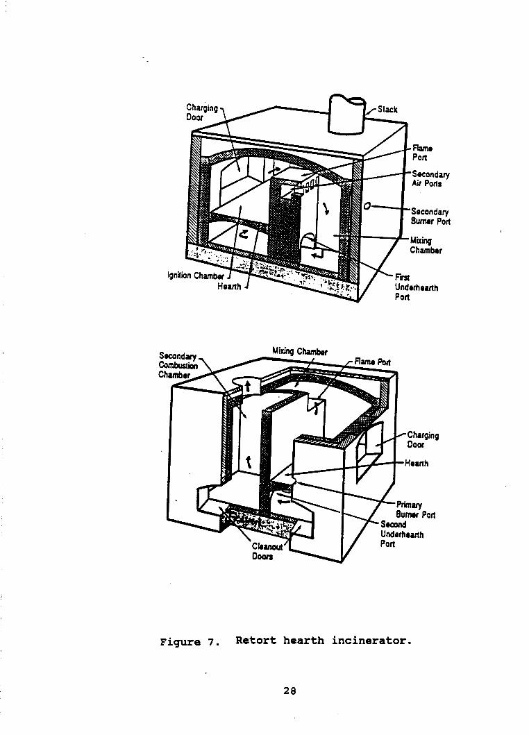
Figure 7 . Retort hearth incinerator.
28
4 . 5 VARIATIONS IN MWI PROCESS COMPONENTS Several process components are integral parts of each of the
medical waste incineration processes. These include waste feed mechanisms, primary and secondary chamber configurations, solids transfer mechanisms, air supply and handling systems, auxiliary burners, ash removal and handling processes, energy recovery options, and stack bypass systems. The variations in these components among the basic MWI processes are described in this section. 4.5.1
MWI's: manual and mechanical. Manual charging involves feeding the waste directly into the primary chamber without any mechanical assistance. This charging system is generally used for batch-fed and small, intermittent-duty MWI's, including pathological systems.
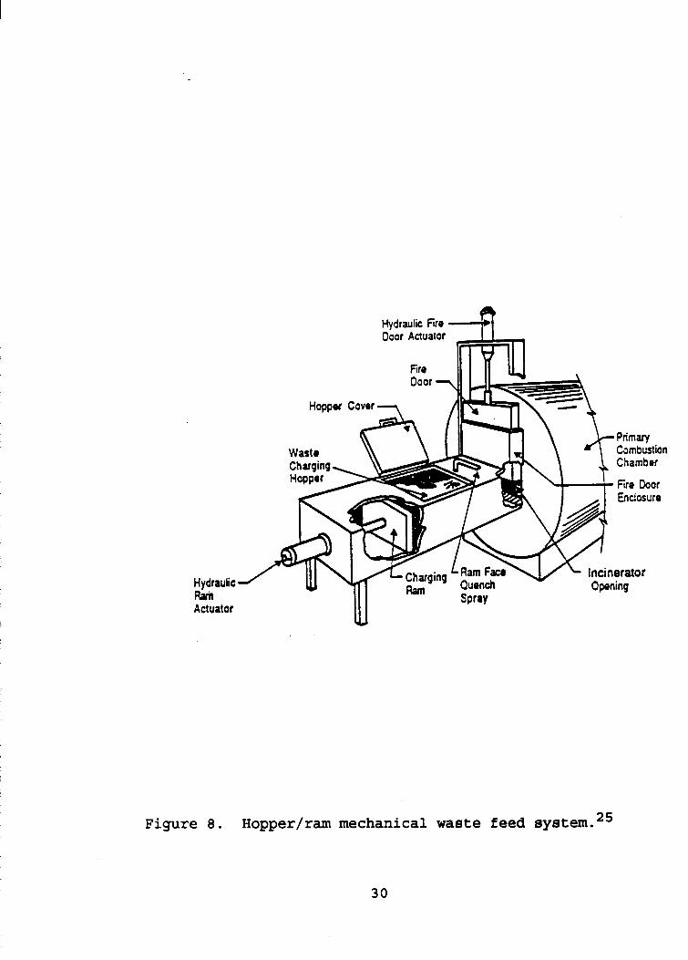
Automatic, or mechanical, equipment for charging the waste is used for all continuous-duty models, including rotary kilns, and for most intermittent-duty MWI's with capacities larger than about 90 to 140 kg/hr (200 to 300 lb/hr), including pathological systems. One mechanical system for charging wastes into the MWI is the hopper/". Some pathological MWI's are fed through top- loading mechanisms. Veterinary facilities, for instance, sometimes use this method of waste feeding when very large animal carcasses are involved.
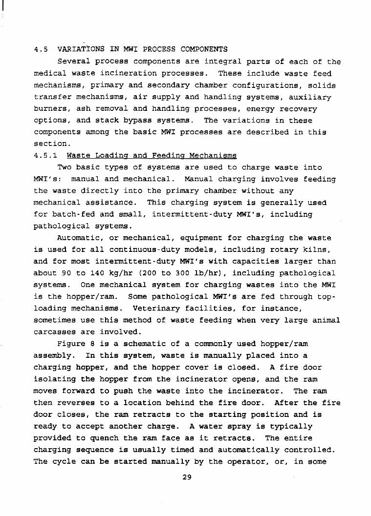
Figure 8 is a schematic of a commonly used hopper/ram assembly. In this system, waste is manually placed into a charging hopper, and the hopper cover is closed. isolating the hopper from the incinerator opens, and the ram moves forward to push the waste into the incinerator. The ram then reverses to a location behind the fire door. After the fire door closes, the ram retracts to the starting position and is ready to accept another charge. provided to quench the ram face as it retracts. charging sequence is usually timed and automatically controlled. The cycle can be started manually by the operator, or, in some
Waste Loading and Feedins Mechanisms Two basic types of systems are used to charge waste into
A fire door
A water spray is typically The entire
29
Hydraulic Fire 4
Hydraulic Ram Actuator
Figure 8. Hopper/ram mechanical waste feed system. 25
30
systems, the cycle starts automatically on a predetermined basis. The charging frequency can be changed by adjusting the length of time between charges in the automatic sequence. The size of the hopper limits the volume of waste that can be fed in each charge; therefore, the size of the charge may be decreased by not filling the hopper to capacity.
In some facilities, mechanical loading equipment is used to deposit the waste material into the waste feeding systems. containers may be lifted and dumped into the MWI charging hopper with no handling of the waste by the MWI operator. automated, computer-controlled systems, the waste container is conveyed to a weighing platform. is recorded, the container is automatically emptied into the feed chute. Controlled amounts of wastes are conveyed from the end of the feed chute to the ram hopper. The door isolating the hopper from the primary chamber is automatically opened at preset intervals, and the wastes are fed into the chamber. early stages of the automatic cycle, prior to charging, the wastes may be subjected to screening sensors to check for radioactivity levels in the waste. 4 . 5 . 2 Primarv C hambe r Variations
4.5.2.1 Primarv Chamber Confiauration. The sizes and shapes of the primary chambers for each of the basic MWI systems vary. The primary chamber of the continuous-duty, rotary kiln is cylindrical in shape and is slightly inclined from the horizontal plane. The primary chamber on other MWI's may be cylindrical, square, or rectangular in shape and may be vertically or horizontally oriented. In all units, the chamber size is designed for a specified volume of waste with a particular Btu content. In intermittent-duty systems, the size of the primary chamber determines the total amount of waste that can be loaded and the amount of ash that can be accumulated without restricting the overall process. For continuous-duty units, the size of the primary chamber will impact the rate of charging and the quality of burnout.
Waste
In fully
After the weight of the waste
During the
Some continuous-duty systems are designed with
31
larger prixkry chambers to accommodate longer solids retention times and more complete combustion of the fixed carbon.
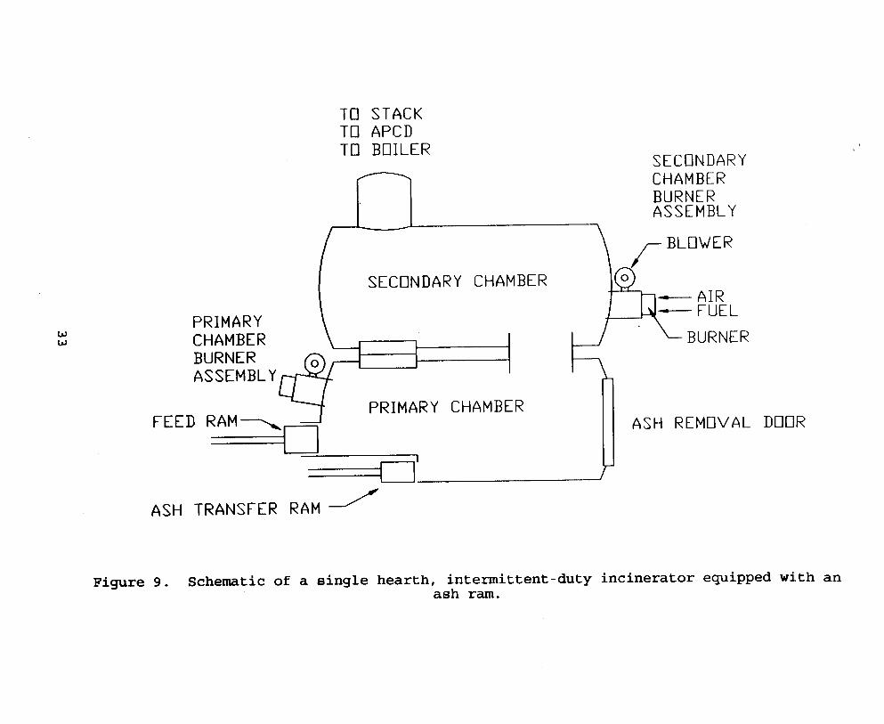
Small MWI's utilizing manual charging and some small MWI's with mechanical charging systems have no means of solids transfer, or agitation. Waste is charged iato the unit until the ash builds up to the point where no more waste can safely be charged. Many MWI's with a single hearth and a waste feed charge ram use the ram to move burning waste and ash across the hearth. As a new load is pushed into the primary chamber, the previous load is pushed forward. Each subsequent load has the same effect of moving the waste across the hearth. Some single-hearth systems also may have an ash ram located below the charge ram at the hearth level. This ram is used both to stoke the burning waste (i.e., agitate the waste bed to expose all surfaces to heat and air) and to move the waste and ash toward the discharge end of the chamber. Stoking may be automatic or manual. Figure 9 is a schematic of a single-hearth, intermittent-duty MWI equipped with an ash ram.
Large, continuous-duty MWI's often have multiple hearths arranged in a stepped fashion. This type of system is shown in Figure 3 .
transfer ram. These internal rams are automatically controlled to operate in sequence to clear off space on each step for the ash pushed off from the previous (higher) step. The ash discharge ram operates first by pushing ash into the ash pit (dry or containing water as a quench). the step behind the ash discharge ram pushes ash from its step onto the ash discharge step. The process of clearing space is repeated back to the waste feed ram, which pushes waste onto the top step, thereby pushing the previous charges onto the space cleared by the ash transfer ram for the next step. causes agitation of the waste, as the ash is moved from hearth to hearth, thereby improving solid-phase combustion.
through the primary chamber. 26
4.5.2.2 Solids Transfer Systems in the Primary C hamber .
The face of each step is that of an internal ash
Then the ash transfer ram for
This system
At least one manufacturer provides a stoker to move waste The stoker consists of a double
32
TO STACK TO APCD TO BOILER
SECONDARY
W W
PRIMARY
CHAMBER BURNER ASSEMBLY
I
SECONDARY CHAMBER - FUEL
CHAMBER BURNER ASSEMBLY
SECONDARY CHAMBER
CHAMBER BURNER ASSEMBLY I
PRIMARY CHAMBER FEED RAM-,-,
// ASH TRANSFER RAM
ASH REMOVAL DOOR
Figure 9. Schematic of a single hearth, intermittent-duty incinerator equipped with an ash ram.
reciprocating grate that mixes the waste and constantly exposes it to heat and oxygen. The stoker comprises a series of overlapping, alternating stationary and movable grates. While a movable grate positioned over a stationary grate is advancing, a movable grate positioned under that stationary grate retracts to form a step 15 inches high. This action causes waste to fall and mix as it moves across the length of the stoker.
One manufacturer offers a Pulse Hearthn in the primary chamber. 27
hearth, a refractory-lined, stepped hearth suspended on the outside of the primary chamber at four points by steel cables. The hearth is pulsed forward and upward by an external pneumatic system. This pulsing action moves the waste forward from the charge end of the primary chamber to the ash removal end.
the cylindrical primary chamber, which is slightly inclined from the horizontal plane. slowly move down the incline toward the discharge end of the chamber.
The entire floor of the chamber consists of the pulse
Rotary kilns mix and transfer solids through the rotation of
The solids are tumbled within the kiln and
4.5.2.3 Auxiliarv Burners. In the primary chamber, with the exception of pathological MWI’s, auxiliary burners are used only to ignite the waste. Once the waste has started to burn, the primary chamber auxiliary burners are rarely, if ever, needed again. Typically, the setpoint for these burners is about 43OOC (800°F), so that if the chamber temperature falls below the setpoint, the burner comes on. The temperatures in the primary chamber are typically above 538OC (lOOO°F), assuming the MWI is being properly charged with waste. In pathological MWI’s, the auxiliary burner usually stays on because the heating value of the pathological waste (2,330 kJ/g [ 1 , p O O Btu/lbl) is not high enough to sustain combustion and, therefore, requires additional heat from the burner for combustion.
primary chambers of MWI‘s primarily as underfire air through air ports by a single forced-draft blower. reduced or increased by adjusting control dampers or by adjusting
4 . 5 . 2 . 4 Air S u m lv and Handling. Air is supplied to the
The air supply can be
34
the speed oE the fan. typically consist of small holes, arranged at regular intervals, built into the floor of the hearth. If the hearth is rectangular or square, the ports typically will be arranged in a regular grid equally spaced or in a series of rows across the hearth. hearth is circular, the ports may be arranged in concentric circles or, if the unit is very small, in one circle.
Several methods are currently in use on MWI’s to control the amount of combustion air to the primary chamber so as to maintain substoichiometric oxygen levels. Because of the relationship between the stoichiometry of the combustion air and temperature, temperature can be used as an indicator of combustion air levels in the chamber. Maximum combustion temperatures are attained at stoichiometric conditions. As the amount of excess air increases above the stoichiometric point, the combustion temperature decreases because of the energy needed to heat the combustion air. However, while in the substoichiometric region, increasing the amount of air towards the stoichiometric point increases temperature as more oxygen becomes available for combustion. A graphical representation of the relationship between combustion temperature and combustion air levels is presented in Figure 10.
In many systems, the primary chamber air systems are automatically, continuously controlled by regulating (or I1modulatingn) the amount of air supplied in order to maintain the desired combustion chamber temperatures, regardless of the variations in waste characteristics (e.g., moisture content, heating value). temperature in the primary chamber. the setpoint, the control feedback loop automatically adjusts (closes) the damper, limiting the air supply into the chamber, thereby reducing the rate of combustion and the thermal heat output. Conversely, if the temperature is below the setpoint, the damper is automatically adjusted (opened) to allow more air in to increase the temperature. In other systems, particularly batch or intermittent-duty systems, the combustion air level control is simplified and may consist of the automatic switching
In fixed-hearth systems, the air ports
If the
One or more thermocouples measure the If the temperature is above
35

i TEMPERATURE
MAXI MUM TEMPERATURE
I EXCESS AIR I SUBSTOICHIOMETRIC AIR
PERCENT EXCESS AIR - Figure 10. Relationship between temperature and combustion
air levels.
36
of the combfistion air rate from a high to a low setting (adjusting damper position or blower speed) when temperature setpoints are reached or at preset time intervals.
combustion air into the kiln through the fixed endplate. Because of the physical orientation of the kiln, the air enters the chamber as overfire air. The air supply is controlled in the same manner as in the intermittent- or continuous-duty systems described above.
Pathological MWI's are designed for surface combustion of the waste, which is achieved predominantly by using a burner and limiting the amount of "underfire airt1 in the primary chamber. In some systems, combustion air ports may be built into the side walls of the chamber. While in all pathological units combustion air comes in through the burner flame port(s), in some units additional excess air ("underfire air") may be introduced through the side wall ports. When burning pathological waste, both air and direct heat are required--first to vaporize the moisture in the layer of tissue and, subsequently, to burn the dried layer. This combustion occurs layer by layer, and, because of its low heating value (2,330 kJ/g [1,000 Btu/lbl), pathological waste requires direct contact by the flame of the primary chamber auxiliary fuel burners.
chamber is equipped with a thermocouple to govern the activation of a water spray when the chamber temperature exceeds a preset value. Some systems use steam injection through underfire air ports to keep the temperature of the ash bed down and to facilitate burnout of fixed carbon in the ash bed. Because steam injection helps to maintain ash bed temperatures below the melting and fusion points of most combustibles, this procedure also helps to prevent clinker buildup and slagging that could
28 plug the underfire air ports.
In rotary kilns, forced draft is used to introduce
4 . 5 . 2 . 5 Other Featu res. In some MWI systems, the primary
37
4.5.3 Secondarv Chamber Variations 4.5.3.1 Secondarv Chambe r Confisuration. - There are several
variations in the configuration of secondary chambers. As with primary chambers, secondary chambers may be cylindrical, square, or rectangular, and they may be vertically or horizontally oriented. Although the secondary chamber of the rotary kiln is sometimes oriented horizontally, it is often vertically oriented to reduce carryover of entrained particulates. usually cylindrical, but it can also have a box-like shape.
and completely oxidize all the volatile gases generated in the primary chamber and to maintain sufficient combustion air so that excess oxygen is available.
The volume of the secondary chamber is the key parameter influencing the residence time of the combustion gases. incinerator is designed for a specified residence time and volumetric flow rate, the secondary chamber is sized accordingly. Some MWI's have a tertiary chamber that serves to increase the residence time of the combustion gases at high temperatures. Thus, the tertiary chamber can be regarded as an extended secondary chamber.
4.5.3.2 Auxiliarv Burnerg. The auxiliary fuel burner(s) are designed to maintain setpoint temperatures, and they operate in conjunction with modulating air controls to maintain these temperatures in the secondary chamber. modulate on and off or are equipped with high and low settings. In some units, fully modulating burners are used.
operate in an excess-air mode. introduced into the secondary chamber through a flame port at right angles (or tangentially) to the incoming combustion gases from the primary chamber, thereby creating a turbulent zone that promotes mixing of the air and combustion gases. applications, combustion air is supplied to the secondary chamber in multiple locations.
The chamber is
All secondary chambers must have adequate volume to accept
If the
The burners either
4.5.3.3 Air SUDD lv and Handling. A l l secondary chambers The excess air typically is
In some
38
Typically, air is supplied to the secondary chamber through a port by a forced-draft blower. This air supply is controlled as described for primary chambers in Section 4 . 5 . 2 . 4 . Some systems, particularly batch- or intermittent-duty units, simply control the combustion air level with automatic switching of the combustion air rate from high to low to rectify deviations from the setpoints.
combustion air stoichiometry and temperature is such that temperature can be used as a control to maintain the appropriate combustion air level. A control feedback loop, based on temperature measured by the secondary chamber thermocouple(s), can be used. This system operates in a manner similar to that described for the primary chamber air supply (see Section 4 . 5 . 2 . 4 ) . However, because the secondary chamber has an excess-air environment, when the temperature is too high (above the setpoint), the damper is opened to admit more air, and when it is too low (below the setpoint), the damper is shut to limit the air supply. 4 . 5 . 4 Ash Removal and Handlinq
continuous or periodic. on continuous-duty MWI's, including rotary kiln MWI's. These continuous ash removal systems may be dry or wet processes. In either system, ash falls off the end of the hearth or kiln into an ash discharge chute. In the dry system, the ash discharges directly into an ash container positioned within an air-sealed chamber. When the container is full, it is removed from the chamber and replaced with an empty ash container. process, the ash is discharged into a water pit. quenches the ash, and it also forms an air seal with the incinerator. A mechanical device, either a rake or a conveyor, removes the ash from the quench pit intermittently or continuously. as it is removed from the pit, and the wetted ash is discharged into a collection container.
As discussed in Section 4 . 5 . 2 . 4 , the relationship between
Ash removal and handling systems may be classified as Continuous ash removal systems are used
In the wet The water bath
The excess water is allowed to drain from the ash
39
Manual-ash removal typically involves removing ash by raking and shoveling the ash into metal containers. Generally, this removal occurs the morning after the burn, once the MWI has cooled, and it is safe to remove the ash. Manual ash removal is practiced on almost all MWI's without a continuous ash removal system. Some systems include an ash ram that pushes some of the ash from the incinerator. However, manual removal of the remaining ash is still required in these units. 4.5.5 Enersv Recoverv
The heat generated during incineration can be recovered and used to generate hot water or steam. often recover heat from the stack gases are those with larger MWI systems. Most often, a waste heat recovery boiler is installed and used to generate steam and/or hot water. However, heat exchangers are also used to recover heat.
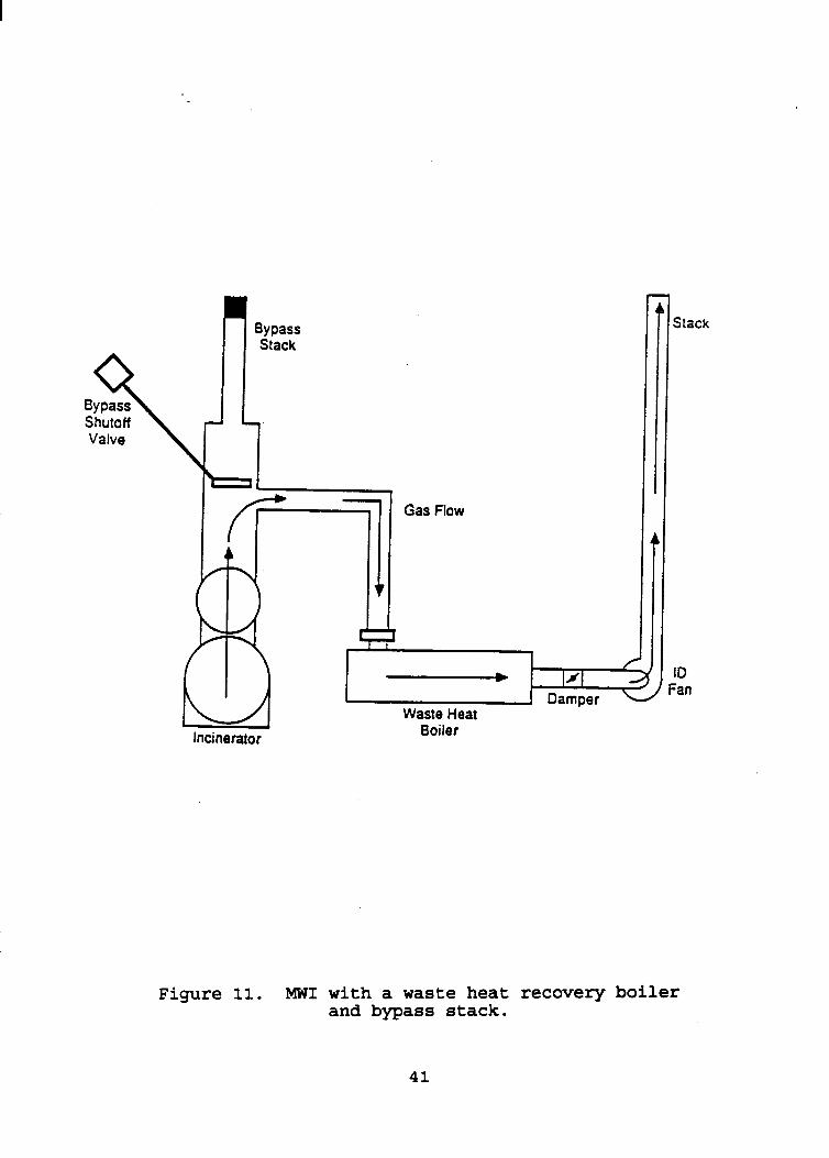
as an option with their incineration units. Figure 11 is a schematic of an MWI with a waste heat recovery boiler. The combustion gases from the incinerator pass through the waste heat boiler prior to being emitted to the atmosphere. heat boiler is used, an induced draft fan must be added to move air through the system.
chamber exhaust gases before they enter an air pollution control system. limitations and/or economics prevent the installation of a waste heat boiler for energy-recovery purposes. 4.5.6
a waste heat boiler (or an air pollution control system) is included as part of the system. causes a resistance (blockage to airflow) in the system if the induced draft fan stops, pressure can build up in the incinerator if the hot gases cannot escape quickly enough. The bypass stack is added to allow a route for the hot gases to escape should the fan fail. In other words, it allows the incinerator to go back
The facilities that most
Incinerator manufacturers often provide waste heat boilers
When a waste
Heat exchangers are sometimes used to cool the hot secondary
These systems are used for situations in which space
An emergency bypass stack is typically added to an MWI when
Because a waste heat boiler
40
Shutoff Valve
f
Bypass Stack
/ - 131 - Fan
, Damper Waste Heat
Boiler Incinerator
Stack
ID
Figure 11. MWI with a waste heat recovery boiler and bypass stack.
41
to a natural draft system. The bypass stack is also used in cases where the boiler must be bypassed for safety reasons or operational upset conditions (e.g., l o s s of water flow to the boiler, causing heat buildup). Another purpose of the bypass stack is to protect the air pollution control device when a system malfunction could result in damage to the device. The combustion gases can be routed through the bypass stack to avoid contact with the control device in these cases.
The bypass stack usually contains a damper valve to control direction of the gas flow or a cap on top of the stack to prevent air from being pulled into the system when the fan is operating. If the bypass must be activated, the damper or cap is opened automatically by some type of sensor; for example, if the fan speed falls below a preset level, the bypass opens. Figure 11, the schematic of an MWI with a waste heat boiler, illustrates a typical position of the bypass stack in the duct between the outlet of the secondary chamber and the waste heat boiler. 5.0 CHARACTERIZATION OF EMISSIONS
The pollutants emitted from MWI's include PM; metals; organics, including CDD's and CDF's; CO; and the acid gases HC1, SO2, and NO,. These pollutants exist in the waste feed material or are formed in the combustion process, but the primary point of emissions release is the combustion stack (i.e., combustion gases from the secondary chamber). Because of the high temperatures typically encountered and because of the turbulent conditions and adequate residence time in MI'S, pathogens are expected to be completely destroyed in the combustion process. stack emissions, there are potential sources of fugitive emissions of these pollutants in the MWI process. discusses the generation and emission of the pollutants from the combustion process and from fugitive emission sources. various factors that affect emissions are discussed in Section 5.2. Section 5.3 presents emission test data. Section 5.4 presents existing emission limits (based on existing requirements for MI'S).
In addition to
Section 5.1
The
42
5.1 SOURCES OF EMISSIONS 5.1.1 Combustion Stack
Pollutants in the combustion gas stream from the secondary chamber are emitted with the gases through the stack. The pollutants that are likely to be emitted through the stack as a result of the combustion process are discussed in this section.
There are two types of PM: inerts (ash) and products of incomplete combustion (soot). The noncombustible portion of the waste feed represents those materials that will not burn under any conditions in the incinerator. Emissions of noncombustible materials result from the suspension or entrainment of ash by the combustion air added to the primary chamber of the incinerator. The more air added, the more likely that noncombustibles will become entrained in the primary chamber and be emitted with the flue gas. While entrainment is the primary mechanism for ash PM emissions, soot formation also plays a role in PM emissions. Soot, which is primarily elemental carbon, is a product of incomplete combustion.
Metal emissions depend upon the characteristics of the feed material. instruments or utensils; in plastics, paper, pigments, and inks; or as discarded heavy metals used in laboratories. Trace metals present in medical waste materials include lead, cadmium, mercury, chromium, antimony, arsenic, barium, beryllium, nickel, silver, and thallium. Emissions of these metals are generated during the combustion process as a consequence of entrainment or volatilization. Unlike organic constituents, metals are not "destroyed" during the combustion process. Rather, they are distributed or partitioned among the incinerator effluent streams. As a result of this partitioning effect, metal constituents can leave the primary chamber as bottom ash or in the combustion gas. between these streams is based on such factors as the chemical form of the metals charged to the combustor, the localized reaction atmosphere in the primary chamber, localized chamber temperatures, and localized airflows.
Metals may exist in the waste as parts of discarded
The relative distribution of the metals
Many metals are converted
4 3
to oxides o r chlorides during combustion and are emitted primarily as entrained submicron- to micron-sized particles. Metals that volatilize at primary combustion chamber temperatures may exit the system as a gaseous component of the air stream or may selectively condense on small particles in the incinerator combustion gas. waste ash, the following are generally thought to exhibit such fine-particle enrichment: arsenic, cadmium, chromium, nickel, lead, and antimony.
formation of water (H20) and carbon dioxide (C02). The concentration of CO in the incinerator exhaust gas stream is an indicator of the combustion efficiency of the unit and is primarily related to gas-phase combustion conditions in the secondary chamber. the reaction between carbonaceous fuels and oxygen. Combustion conditions that result in incomplete combustion produce elevated levels of CO, as well as PM and organics.
Inadequate gas-phase combustion conditions in the secondary
Of the metals known to be present in medical
29
Complete combustion of organic materials results in the
Carbon monoxide is an intermediate product of
chamber also favor increased organic emissions. emissions can originate directly from the vaporization of organic material present in the waste, new organic species can be formed during combustion as a result of the complex chemical reactions occurring during the combustion process. available (for example, from PVC or other chlorinated plastics), the organics generated can include highly toxic chlorinated organics, such as CDD's and CDF's.
as the chemical compounds found in the waste material, and as N2 in the combustion air. the reaction of the N2 in the combustion air with oxygen or oxygenated species, and the resultant product is referred to as thermal NO,.
factor in HC1 formation and emissions is the availability of chlorine in the feed material. In the presence of available
While these
When chlorine is
Nitrogen enters the MWI as a constituent of auxiliary fuels,
Nitrogen oxides are primarily formed from
The principal acid gas from MWI's is HC1. The determining
44
hydrogen, as would occur in medical waste materials with high organic contents, most of the available chlorine is converted to HC1; however, low levels of elemental chlorine do exist in the exhaust gas. Most of the sulfur in the medical wastes is converted to SO2 during combustion, regardless of incinerator design or operation. 5.1.2 Fugitive Emissions
gases (including unburned volatile materials), PM, and pathogens. Emissions of combustion gases can occur when charging wastes into the incinerator and from leakage through improperly sealed doors. Fugitive emissions of combustion gases may also accumulate in poorly ventilated areas around the primary chamber. Fugitive emissions of PM can occur when handling incinerator ash and when handling and transporting the residue from air pollution control devices (e.g., fabric filters). A potential source of fugitive pathogen emissions is handling unburned medical waste. However, careful handling of medical waste, not overfilling the plastic bags containing the waste, the use of containers on wheels with structural integrity to transport waste, and the use of automated waste charging systems should reduce fugitive pathogen emissions to negligible levels.
Fugitive emissions from the operation of an MWI are usually the result of poor design, operation, or maintenance. Manually fed MWI's are considered to be poor designs from an emissions standpoint because the charging door must be opened to the atmosphere during charging. MWI's helps to alleviate the fugitive emissions problem by eliminating the need to have the primary chamber open directly to the atmosphere. reduce the potential for fugitive emissions. For example, wetting or covering the ash or control device catch before transporting can minimize the possibility of windblown fugitives. Adequate maintenance of door seals, flanges, and auxiliary burner housings also help reduce the possibility of leakage of gaseous emissions to the atmosphere.
There are three types of fugitive emissions: combustion
The "air-lock" feature of ram-fed
Proper precautions when handling waste and ash
4s
5 . 2 FACTORS THAT AFFECT EMISSIONS
The formation, generation, and emissions of all of the pollutants discussed in Section 5.1 depend upon either the availability of certain materials in the waste feed (i.e., waste characteristics) or on the efficiency of the combustion process. Factors involved in combustion process efficiency include MWI system design, operating parameters, startup and shutdown procedures, proper training of the operators, and how well the system has been maintained. section. 5.2.1 Waste Characteristics
As discussed in Section 3.1, medical waste varies considerably in composition and, therefore, in chemical and physical characteristics. Waste characteristics can affect combustion efficiency and pollutant formation. The chemical composition of the waste materials is an important factor in generating emissions. The presence of metals, halogenated materials, and sulfur in the waste feed increases the potential for emissions of PM, metals, organics, SO2, and HC1. Medical waste incinerators are designed to operate under certain conditions, including specific physical attributes of the waste feed. These attributes (e.g., heat content, moisture content, and bulk density) influence MWI feed rates, temperatures, air flow conditions, and residence times - all of which affect emissions of PM, metals, organics, CO, and NO,. If the physical attributes of the waste vary from the design specifications, then the potential for emissions can be affected. 5.2.2 I i i
control of feed charging procedures, temperatures, excess air, turbulence, mixing, and residence time. Because of the variability of the physical properties of medical wastes, incinerator operating parameters need to be adjusted to match the composition of the waste in order to maximize combustion efficiency. In general, increased temperatures and excess air rates, good mixing, and longer residence times in the secondary
These factors are discussed in this
Complete combustion of combustible material requires proper
4 6
chamber result in improved combustion efficiency and lower emissions of PM, toxic organics, and CO. However, incinerator operating parameters have little or no effect on emissions of HC1 and SO2. control feed charging, temperatures, and excess air rates, an operator has only indirect control over turbulence, mixing, and residence times.)
Waste handling and charging procedures may account, in part, for fugitive emission sources. For example, emptying medical waste from its container into the incinerator (instead of leaving it in a disposable container that can be loaded into the incinerator) may result in spillage. Waste charging activities often include segregating wastes and, therefore, can influence the composition of the feed material, incinerator operating conditions, and subsequent stack and fugitive emission characteristics. controls to prevent overfeeding, but in manually fed and batch units, overfeeding can occur. Overfeeding the primary chamber can result in blockage of the air port to the secondary chamber, premature ignition of the waste, and excessive emissions because the rapid generation of volatiles can exceed the capacity of the secondary chamber. Feed volumes and frequency (determined by the waste composition) are responsible for variations in chamber temperatures, which, in turn, affect combustion efficiency and emission profiles.
sustain combustion and to generate sufficient volatile combustion gases. Inadequate temperatures may result in increased emissions of PM, CO, and organics. Temperature also plays a role in the volatilization of metals and the subsequent emission of these as gaseous components of the air stream. Temperatures must be high enough to destroy pathogens and combust fixed carbon. Adjustments that increase combustion temperatures may, however, increase emissions of NO, and trace metals.
operating characteristic that affects emissions.
(It should be noted that although the MWI operator can
Systems with automatic feeders usually have
Temperatures in the primary chamber must be high enough to
The quantity and distribution of combustion air is another The rate of
47
entrainment-of ash in the combustion air added to the primary chamber is likely to increase as more air is added, resulting in a higher rate of PM-entrained trace metal emissions. other hand, low excess-air conditions in the secondary chamber can result in soot emissions. Oxygen concentration and the degree of mixing of the air with the fuel has a direct impact on CO formation. Emissions of organics increase with poor air distribution in the waste bed and inadequate combustion air conditions in the secondary chamber. As airflow rates increase, the residence times in the secondary chamber decrease.
Residence times in the secondary chamber have an impact on emissions. Organic materials present in the medical waste material must be exposed to optimum temperatures long enough to ensure their complete combustion. Emissions of organic species formed as by-products of combustion (e.g., CDD's and CDF's) are affected by the residence times in the secondary chamber if they have already been formed. 5.2.3 System Desiqn
chamber burner modulation does not always result in effective control of the combustion process. rate and chamber temperatures are critical to combustion efficiency, the inability to closely monitor and control these key parameters can result in higher pollutant emissions.
size and shape of the secondary chamber. is sized to provide the desired residence time based on the flow rate for which the unit is designed. secondary chamber whose volume is insufficient to accept and completely oxidize all volatile gases generated in the primary chamber can contribute to pollutant emissions. Section 5.2.2, residence times in the secondary chamber play a critical role in the reduction of emissions of PM, CO, and organics.
primary and secondary chambers is a key operating consideration.
On the
Manual control of air modulation and primary and secondary
Because proper combustion air
Residence time requirements establish constraints on the The secondary chamber
Using a unit with a
As discussed in
For MWI's, the distribution of combustion air between the

Air distribution affects the mount of oxygen that is available for reaction in each chamber and, therefore, influences combustion efficiency and subsequent air emissions.
for promoting the mixing of solids in the primary chamber, burnout may not be complete. Mechanical turbulence of the bed may be used to expose all of the solid waste to oxygen, thereby enhancing the degree of burnout. systems are used to accomplish mechanical turbulence. effective mixing of solids maximizes combustion efficiency, increased emissions of PM may occur as a result of the turbulence.
When MWI’s are not designed to include effective mechanisms
Various hearth designs and ram While
The size of burners specified for MWI’s also affects emissions. ignite the waste, to sustain combustion of the charged waste, and to complete the vapor-phase combustion. provide a rated heat input expressed in kJ/hr (Btu/hr). Specifying improper burner sizes can result in incomplete combustion and a consequent increase in emissions.
removal and handling systems, the repeated manual opening and closing of the ash cleanout door and tightening of the door clamps may damage the seal gasket, which can allow infiltration of outside air around the door face. This infiltration may result in decreased combustion efficiency and a subsequent increase in emissions. 5 . 2 . 4 1 wn Pr r
that vary depending upon the type of unit. startup procedures are charging the waste, preheating the secondary chamber, and activating the combustion air blowers. Startup procedures for batch-feed units also include removing the ash from the previous cycle and sealing the charge door. Shutdown of a continuous-duty incinerator involves stopping the charging process and maintaining temperatures in the secondary chamber until the remaining waste burns down to ash and is
The burners provide the heat required to initially
Burners are designed to
For MWI systems that are designed without automated ash
Startup and shutdown of a MWI involves special procedures Included in the
49
discharged-from the system. units, shutdown procedures include increasing the combustion air level in the primary chamber and maintaining the temperature in that chamber at a minimum setting for a predetermined length of time to ensure that the fixed carbon is combusted. In addition, the secondary chamber temperature is maintained at a level sufficient to complete the vapor phase combustion of material exiting the primary chamber. When this burndown period is complete, the cooldown period is initiated. If not conducted properly, any of these startup or shutdown procedures may result in increased emissions. These emissions could occur as a direct result of the procedure (e.g., removing ash or charging the waste) or as an indirect result, i.e., reduced combustion efficiency. 5.2.5 ODe rator Traininq
The success of incineration as a technique for treating medical waste depends on the proper operation of the incinerator. The operator is in control of many of the factors that affect the performance of an MWI, including: (1) waste charging procedures, (2) incinerator startup and shutdown, ( 3 ) monitoring and adjusting operating parameters, and ( 4 ) ash handling. An
operator without adequate training will probably not be sufficiently aware of the relationship between MWI process components and potential air pollution problems to be able to avoid or minimize these problems. 5.2.6 Preventive M a intenance
For intermittent-duty and batch-feed
Without an effective MWI preventive maintenance program, the frequency of inefficient operation conditions, upset situations, and air pollution episodes increases. Observations made during the EPA emissions testing program illustrate the importance of an effective maintenance program. At one facility, the lack of routine maintenance was reflected in inoperative burners, malfunctioning relays, clogged air ports, cross-wired lead wires in the control box, improperly wired thermocouple assemblies with chipped insulation, and several other conditions that resulted in a poorly operated unit. These conditions contributed to the
50
unit's severely limited burning capacity, very poor burnout of waste, and a greater amount of visible emissions than would normally be expected. At another site, maintenance-related problems included malfunctioning hydraulic cylinders and pumps in the automatic ram system and a problem with the switch on the gate in that system. open after the ram cycle was completed and, because of the disruption of airflow, increased visible stack emissions. Problems at a third site involved a disabled primary chamber underfire control damper, a nonfunctional control arm on a secondary chamber air blower modulation damper, and seals in need of replacement. Additional maintenance-related conditions included an improperly programmed process control loop, which caused the hopper lid to open t oo soon after the charging ram retracted. Each of these circumstances contributed to substandard operating conditions and, therefore, resulted in increased emissions. 5.3 EMISSION RATES
These problems caused the gate to remain
During the development of background information on MWI's, numerous emissions test reports and test report summaries were obtained. provide emission test data. certain information on the MWI process design and operating conditions, as well as details on the test methods used for testing, must also be available. In almost every case, the test reports obtained were incomplete, in that information on the design and operation of the MWI during testing was not provided. Table 5 presents the post-combustion emission rates (i.e., in the stack for facilities without an pollution control device and between the incinerator and air pollution control device at other sites) for eight tests that were performed at seven test sites as part of EPA's MWI test program. The emission rates are presented in three different formats: Table Sa is presented in metric units; Table 5b is presented in English units; and Table 5c is presented in pounds of emissions per year.
Approximately 25 of these reports and report summaries For test data to be most useful,
51
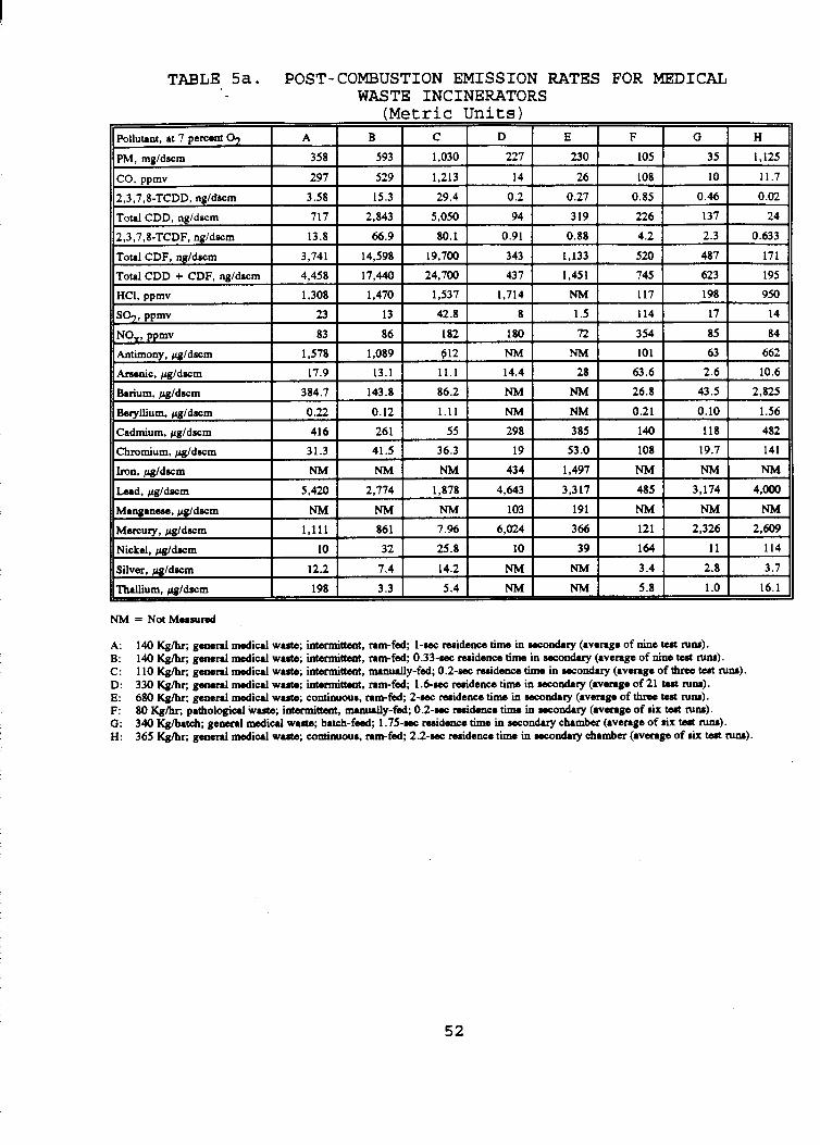
TABLE Sa. POST-COMBUSTION EMISSION RATES FOR MEDICAL WASTE INCINERATORS
(Metric Units)
2,3,7,8-TCDF, ng/dscm
N M = Not Measured
A: B: C: D: E: F: 0: H:
I40 K g k , general medical waste; intermittent, ram-fed; 1-wc nridence time in wcodry (average of nine test NM). 140 K g k , general medid waste; intermittent, ram-fed; 0.33-ra: nridence time in wconduy (average of nine test NM). 1 10 K g k , general medid waste; intermittent, nunually-fed; 0.2-wc reaideme time in w c o d ~ r y (average of three tut NM). 330 Kghr; general medical wa- intermittent, ram-fed; 1.6-w reriden- time in wcondAy (average of 21 test NM). 680 K g k , general medid waste; continuour, ranfed; 2-wc residence time in wcodry (average of &rea test NM). 80 K g k , pathological waste; intermittent. d y - f e d ; 0.2-wc reaidace time in wcondAry (avmge of six test NM). 340 Kghatch; general medid wute; batch-fed; 1.75-wc m i d m time in secondary chamber (average of six test NM). 365 Kghr; general medical warn; continuour, ram-fed; 2.2-wc residence time in wcodry chamber (average of rU test NM).
52
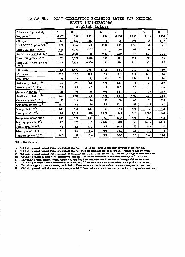
TABLE 5b. POST-COMBUSTION EMISSION RATES FOR MEDICAL WASTE INCINERATORS
NM = Not Mmsured
A: B: C: D: E: F: G: H:
300 I b k , general medical waste; intermittent, ram-fed; 1-MC residence time in wfond.ry (average of nine test IUM). 300 Ibhr; general medical wa-. h”t , ram-fed; 0.33-KC reside- time in r s c o d y (average of nine test ~uM). 250 Ibhr; general medical waste; ht”t, “udly-fed; O.~-MC residence tima in rscodry (average of &me twt IUM). 720 Ibhr; gemed medical waste; in”itCsnt, ram-fed; 1.6-MC residence time in rsc0nd.y (average of 21 test mu). 1,500 I b h . gonod medical waste; continuour, ram-fd, 2-MC residence time in rsconduy (average of &me tost IUS). 175 Ibhr; pathological waste; intamittent, nunudy-fed; 0.2-MC residence time in ucodty (average of nix tost IUM). 750 Iblbatch; general medical waste; batch--, ~ . ~ S - M C residence time in rsc0ad.y chmber (average of six test IUS). 800 Ibhr; general medical waste; continuous, ram-fed; 2.2-MC residence time in rcr0nd.y clumber (average of n u twt IUM)
53

TABLE 5C. POST-COMBUSTION EMISSION RATES FOR MEDICAL WASTE INCINERATORS (Pounds Per Year)
~~
co 1,200 2,100 4,900 220 610 43 5 35 576
<0.01 0.0007 2,3,7,8-TCDD, (10-9 0.015 0.05 0.1 <0.01 0.09 <0.01
~ o t l i CDD, (10-3) 2.5 10 18 1.2 7 0.8 0.4 0.8
2,3,7,8-TCDF, (10-3 0.05 0.2 0.3 <0.01 0.02 0.02 <0.01 0.02
Totri CDF, (10-3) 13 52 70 5.2 29 1.8 1.5 5.7
II Pollutant
T ~ U I CDD + CDF. (10-3)
11 PM I c i 7 0 I 2,200 I 3,650 I 3,000 I 4,940 r- 375 I TI FII
804
16 62 90 6.4 36 2.6 1.9
6,800 8,OOO 8,OOO 32,230 I N M I 6001 890
so2 NO, Antimony
Arsenic
Barium
215 120 395 270 85 1,050 138 1,575
550 580 1,200 4,400 3,150 2,350 477 4,428
6 3.8 2.2 NM NM 0.35 0.2 23.8
0.07 0.05 0.04 0.18 0.6 0.23 <0.01 0.38
1.4 0.5 0.3 1 NM NM 0.09 0.14 101
Beryllium
Cadmium
Chromium
Lead
<0.01 <0.01 <0.01 N M NM <0.01 <0.01 0.06
1.5 0.9 0.2 4.0 8 .O 0.5 0.4 17.3
0.12 0.14 0.13 0.26 1.2 0.38 0.06 5 .08
20 9.5 6.5 59 70 1.8 10 144
Mercury
Nickel
Silver
Thallium
A: B: C: D: E: F: Q: H:
- ~
4 .O 3.1 0.03 77 8.3 0.43 7.3 95
0.04 0.1 0.1 0.13 0.9 0.6 0.04 4.12
0.05 0.05 0.05 NM NM 0.01 <0.01 0.13
0.7 0.01 0.02 NM NM 0.02 <0.01 0.56
300 Iblhr; general medical wallte; intermittent, ram-fed; 1-sec midence time in secondary (avenge of nine tsrt NM).
300 Ibhr; general medical wanto; intermittent, nm-fed; 0.33-sec midence time in secondary (avenge of nine teat rum). 250 Iblhr; general diu1 waste; intermittent, d y - f e d ; 0.2-sec residence time in secondary (average of three test NM).
720 I b h ; g e n d d i u l waste; intermittent, ram-fed, 1.6-m residence time in secondary (average of 21 teat CUM).
1,540 Ibhr, general mediul waste; continuour, ram-fed; 2-sec residence time in secondary (average of thrw test runs). 175 Iblhr; pathological waste; intermittent, rmnurlly-fed; 0.2-sec residence tima in secondary (average of r u tad NM).
750 Iblbatch; general medical waste; batch-fed; 1.75-sec widence time in secondary chamber (average of rix tsrt NM). 800 l b k , general mediul waate; continuour, ram-fed; 2.2-sec residence time in secondary chamber (average of six tad ~uM).
5 4
The MWI‘s tested as part of the EPA size from about 110 kg/hr ( 2 5 0 lb/hr) to (1,500 lb/hr). One unit is a batch-feed
test program range in about 680 kg/hr MWI with a capacity of
about 340 kg/batch (750 lb/batch). The smallest unit is a manually-fed, intermittent-duty MWI that can incinerate nonpathological (general medical) waste or pathological waste, and the largest unit is a continuous-duty MWI with automatic feeding. The secondary chamber residence times range from about 0.2 sec to 2.0 sec. Five different MWI manufacturers’ products were tested during the test program. Units A, B, and D were tested over a wide range of waste feed charging conditions.
As can be seen in Table 5, the degree of variation in emissions from unit to unit is much greater for some pollutants than for others. For the pollutants that are directly impacted by the secondary chamber designs (PM, CO, and CDD + CDF), units D, E, and G show a significant improvement over units B and C. The secondary chamber residence time for units D, E, and G is about 1.6 to 2.0 sec, whereas for units B and C, the time averages about 0.2 sec. residence time, are between the averages for the other units.
secondary chamber conditions (HC1, SO2, NO,, and metals) are dependent on the characteristics of the waste. Pollutants such as arsenic, chromium, lead, and nickel vary only slightly among the six MWI’s burning general medical waste. pollutants such as mercury, cadmium, and thallium show significant variations from site to site. apparently a function of the practices of the hospitals with respect to purchase and disposal of items that contain these pollutants.
on the measured emission rates from the eight EPA tests to present the reader with an understanding of the magnitude of emission rates from MWI’s. These averages are presented in Tables 6a (Metric units) and 6b (English units).
Emissions from unit A, with a 1.0 sec
Emission rates for pollutants that are largely unaffected by
Some other
These variations are
Average post combustion emission rates were calculated based
55
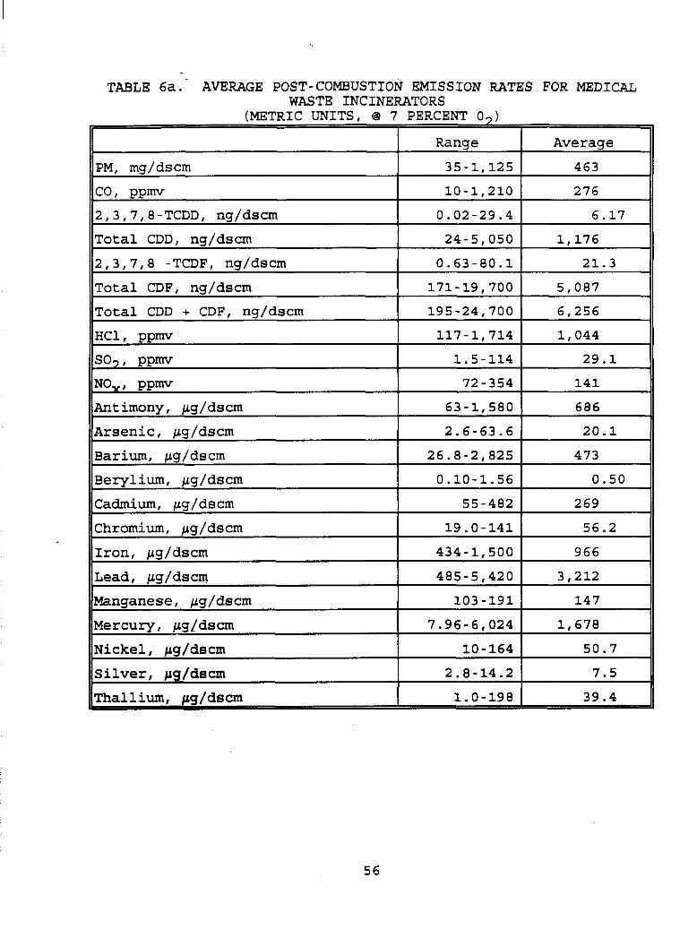
TABLE 6a. AVERAGE POST-COMBUSTION EMISSION RATES FOR MEDICAL WASTE INCINERATORS
56
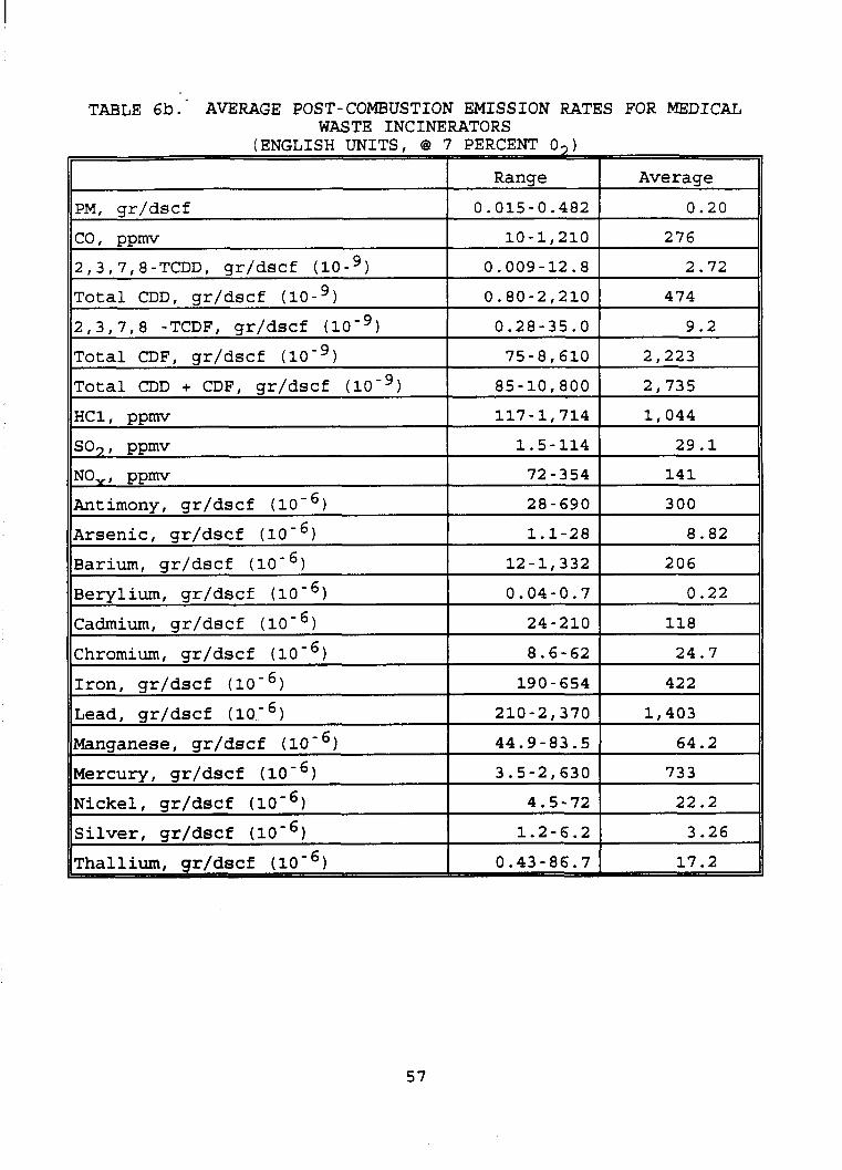
(ENGLISH UNITS, 0
PM, gr/dscf
co, ppmv 2,3,7,8-TCDDf gr/dscf (lo-’) Total CDD, gr/dscf (lo-’) 2 ,3 ,7,8 - TCDF , gr/dsc f ( 10 - Total CDF, gr/dscf (lo-’)
Total CDD + CDF, gr/dscf (lo-’)
HCL ppm
so,, ppm
NO,, ppm Antimony , gr/ds c f ( 10 - 1
Arsenic, gr/dscf Barium, gr/dscf Berylium, gr/dscf (
Cadmium, gr/dsc f ( 10 - Chromium, gr/dscf Iron, gr/dscf Lead, gr/dscf (
Manganese, gr/dscf Mercury, gr/dscf Nickel, gr/dscf Silver, gr/dscf (10- 1
57
7 PERCENT 0,)
Range Average 0.015-0.482 0.20
10-1,210 276
0.009-12.8 2.72
0.80-2,210 474
0.28-35.0 9.2
75-8,610 2 , 223 85-10,800 2,735
117-1,714 1,044
1.5-114 29.1
72-354 141
28-690 300
8.82 1.1-28
12-1,332 206
0.04-0.7 0.22
24-210 118
8.6-62 24.7
190-654 422
210-2,370 1,403
44.9-83.5 64.2
3.5-2,630 733
4.5-72 22.2
1.2-6.2 3.26
0.43-86.7 17.2
5 . 4 EXISTING EMISSION LIMITS The majority of the States have promulgated or are proposing
regulations or permit guidelines specific to MWI’s. Tables 7 and 8 summarize this regulatory activity for new and existing units, respectively. Proposed and final regulations, as well as applicable guidelines, have been included.
are in the process of being revised. There is a wide variability in the requirements from State to State. This variability extends to regulatory format, pollutants addressed, emission limits, affected facility definition, size cutoffs, and operating parameters. For example, some State limits are expressed in terms of pounds of PM per pound of waste charged to the incinerator (lb/lb), while others are expressed in terms of grains of PM per dry standard cubic foot (gr/dscf) of stack gas. Some States use permit conditions rather than formal regulations, and even these may vary from site to site.
HC1, the range of the emission limits is very wide. For PM, the range covers an order of magnitude. In the case of HC1, not only is there a wide range of requirements for emission reduction, but the emission limits are expressed in many different formats, including percent reduction, lb/hr, and parts per million dry volume (ppmdv) .
Frequently, States have different emission limits for different sizes or capacities of incinerators. Two- and three- tiered regulations are not uncommon. limits on some or all MWI’s can be achieved without add-on controls. The levels at which size cutoffs are established are not consistent among the States. Furthermore, an incinerator may be subject to different regulations depending on the age of the unit and the type of waste burned.
The States have established a wide variety of equipment and operating standards for MWI’s to ensure proper operation. These standards include various minimum secondary chamber temperatures and gas residence times, minimum primary chamber temperatures,
The State regulations are generally very complex, and many
While the most frequently regulated pollutants are PM and
In many States the emission
5 8
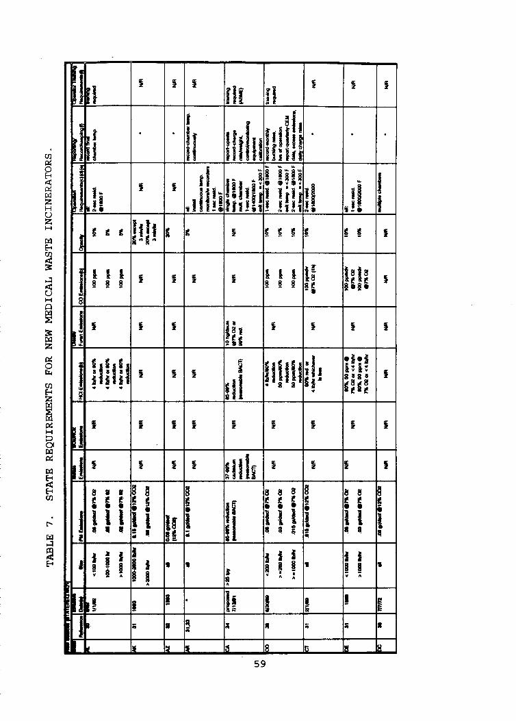
v1 p: 0
3 w u z H
W
E
!? ?
a u H
i2 E z p! 0 E
v1
f W p! H 3 01 W p!
W I3
v) E
l-
W
ii I3
~ 6' /I f I
s 9
I
:q ' A
59

I
s
I 1
5 1 I 1
s 1 If I i
I I
5
c
! I 4 5 I
C f f
I
0 8 8
ft 4 : t :
it 8
60
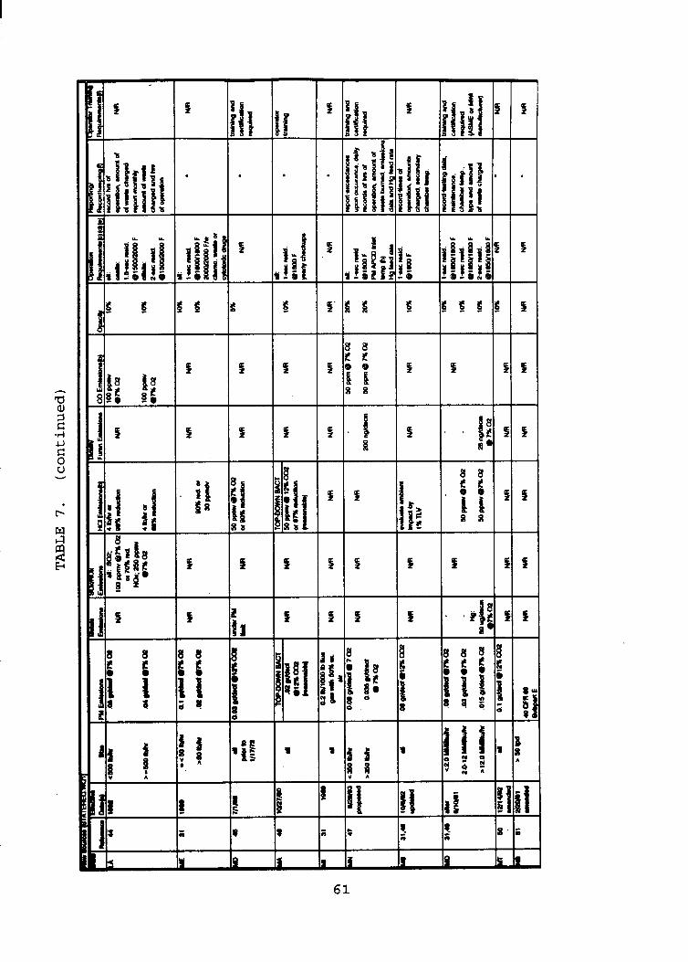
CI
W
4 E
I
L l a
t
b
I I I I I I I I
61
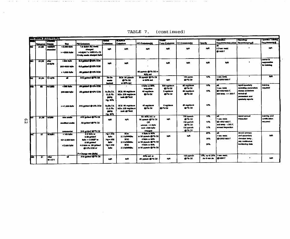
TABLE 7. (continued)
nm m m w
m
-os;ap I
m
I*R I o . s c r r r c r . I
I-' I
.". OlP(Y1yI) F
" I
MI
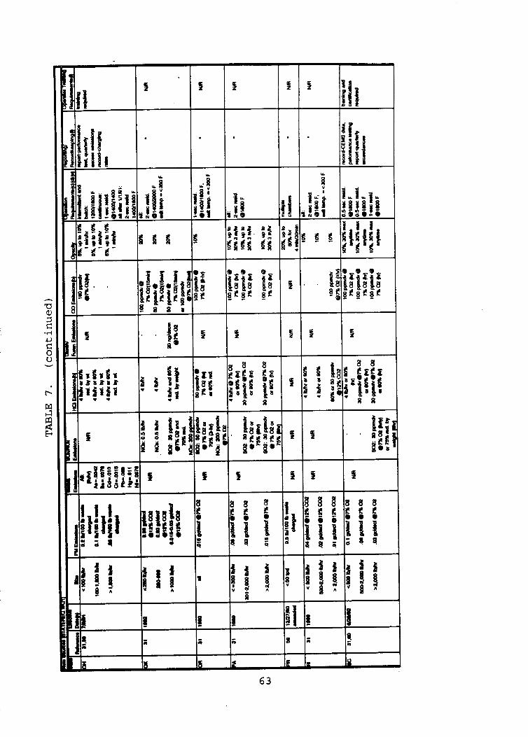
c
T
C
& C C c
a r r
-I-
L
r
F
E i
I I I I 1
s I
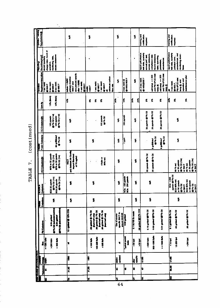
L
f f
9 9
r I
’ 1; L3@
s
9 I
I I I
1 ’ 1
IE 3 k Is I 64
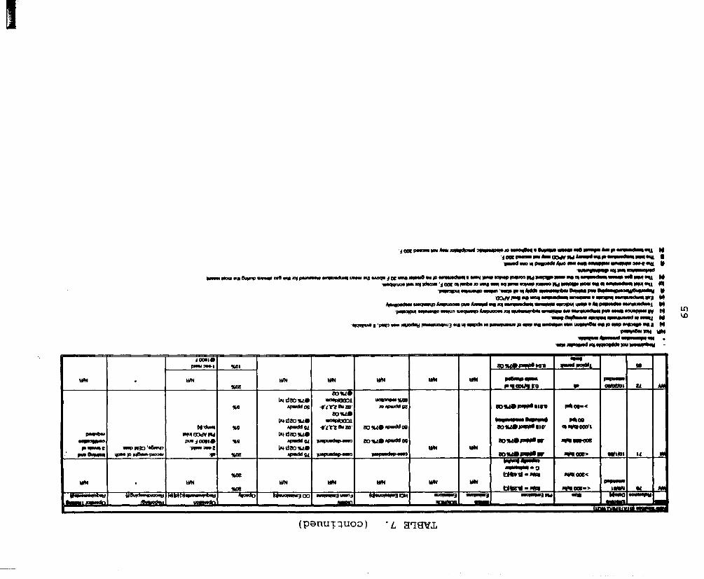
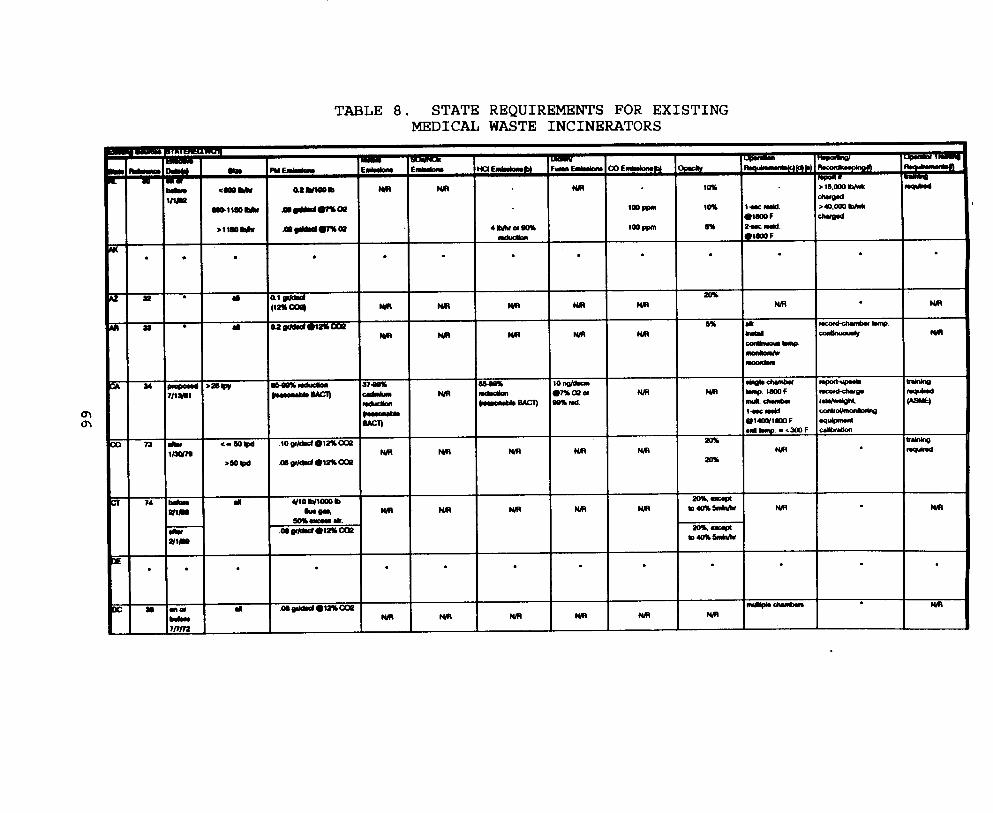
TABLE 8. STATE REQUIREMENTS FOR EXISTING MEDICAL WASTE INCINERATORS
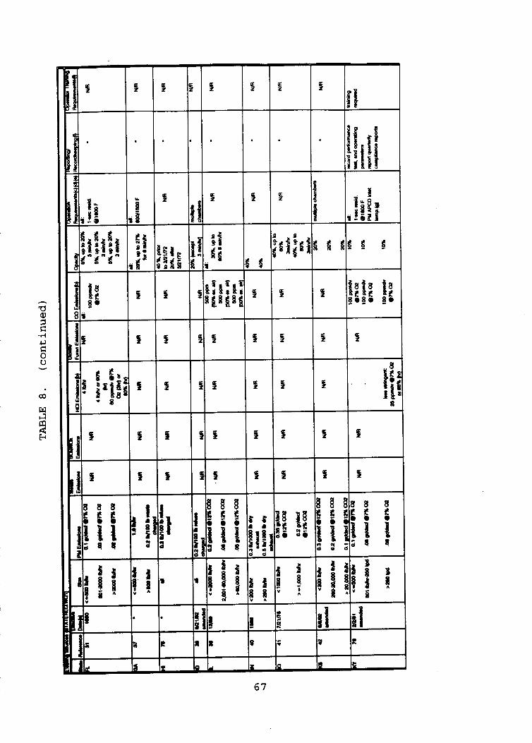
h
I 9 9 9 9 9
I
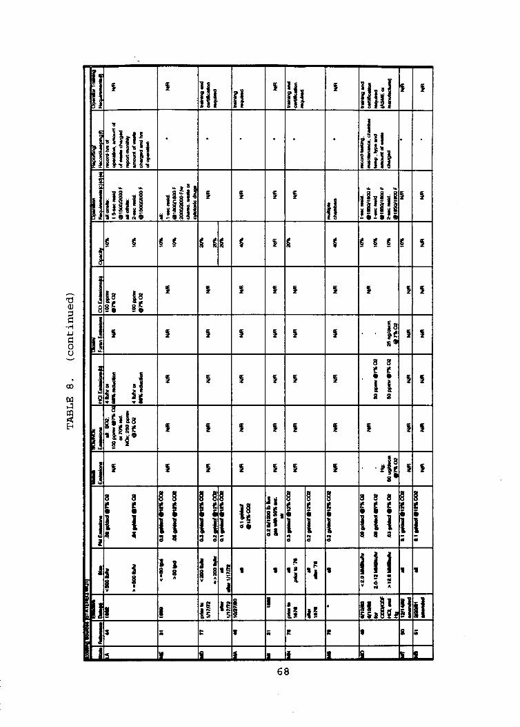
1
9 L
9 9
9
9 9 9
4 9 4
8 8 $ $ B B a a
S 4
4
I 8 8
i C f ! ? ?
I
u 68
L

69
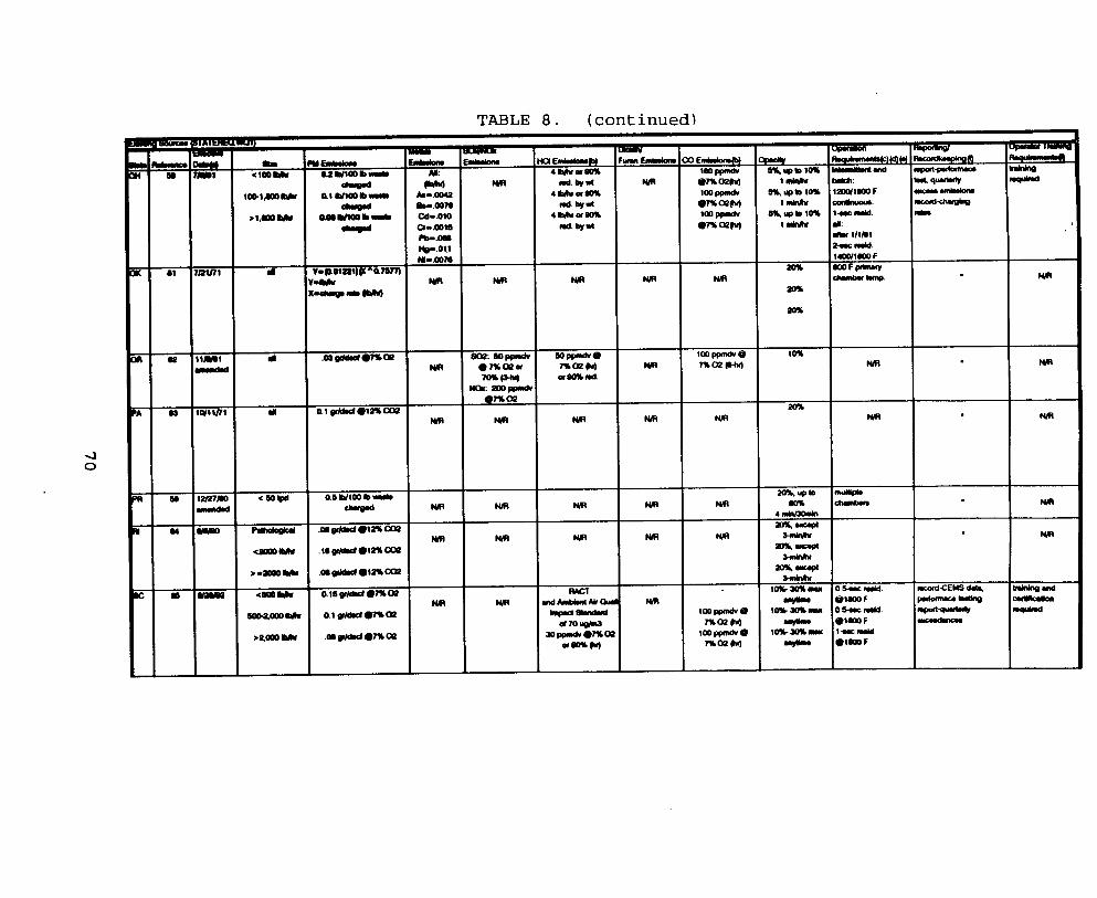
TABLE 8 . (continued)
4 0
I I I *.am I I I
I I 20%
NIR
NIR
I
I I w ’laoF I
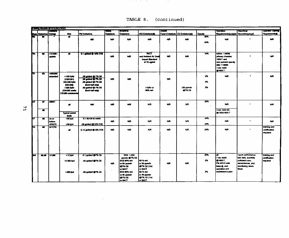
TABLE 8. (continued)
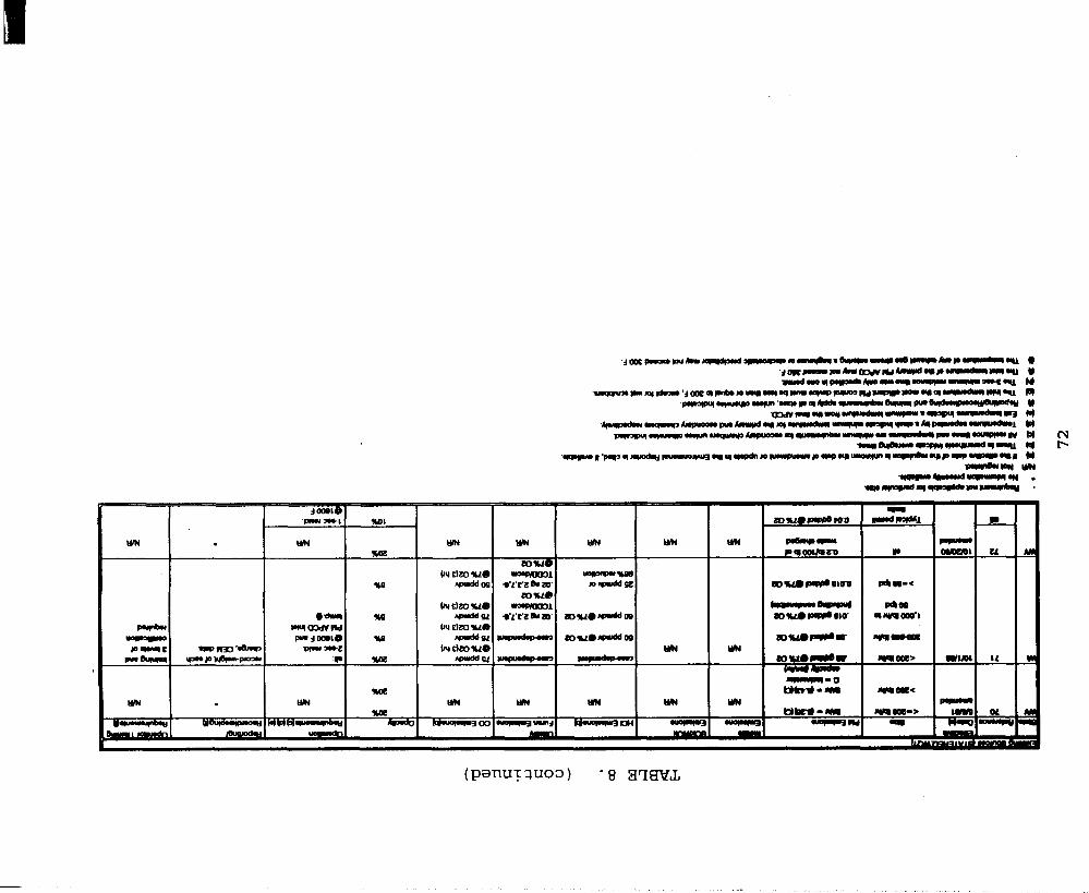
I I I I I LYN I -
and required interlock systems to prevent waste charging when the chamber temperature is below a specified value. These standards vary from State to State and may be tiered for different incinerator sizes. Several states also have requirements for operator training programs. 6.0
1.
2.
3.
4.
5.
6.
7.
8.
9.
10.
REFERENCES
U.S. Environmental Protection Agency. EPA Guide for Infectious Waste Management. EPA/530-SW-86-014. (NTIS PB86-199130) U.S. EPA Office of Solid Waste. May 1986.
U.S. Environmental Protection Agency. Standards for the Tracking and Management of.Medica1 Waste: Interim Final Rule and Request for Comments. Washington, D.C. Federal Resister 3:12373, 12374. March 24, 1989.
Ontario Ministry of the Environment. Operating Criteria, Volume I1 - Biomedical Waste Incineration. October 1986.
Incinerator Design and
Barbeito, M. and M. Shapiro. IIMicrobiological Safety Evaluation of a Solid and Liquid Pathological 1ncinerator.I' Journal of Medical Primatology, Vol 6, 264-273. 1977.
McRee, R. Operation and Maintenance of Controlled-Air Incinerators. Ecolaire Combustion Products. (Undated).
Letter and attachments from R. Massey, Consumat Systems, Inc., to J. Farmer, U.S. Environmental Protection Agency. February 1990. Response to Section 114 information request to MWI manufacturers.
Letter and attachments from G. Swann, Joy Energy Systems, Inc., to J. Farmer, U.S. Environmental Protection Agency. February 23, 1990. Response to Section 114 information request to MWI manufacturers.
Letter and attachments from K. Wright, John Zink, to J. Farmer, U.S. Environmental Protection Agency. March 2, 1990. manufacturers.
Response to Section 114 information request to MWI
Memorandum from D. Randall, MRI, to Project File. April 30, 1992. Summary of data provided by hospitals and commercial facilities in response to Section 114 information request.
Memorandum from D. Randall and T. Holloway, MRI, to Project File. April 30, 1992. Summary of process data from EPA and non-EPA emission tests.
73
11.
12.
13.
14.
15.
16.
17.
18.
19.
20.
21.
22.
23.
Letter-and attachments from T. Kendron, Simonds Manufacturing Corp., to J. Farmer, U. S. Environmental Protection Agency. April 9, 1990. Response to Section 114 information request to MWI manufacturers.
Letter and attachments from J. Basic, Sr., John Basic, Inc., to J. Farmer, U.S. Environmental Protection Agency. February 26, 1990. Response to Section 114 information request to MWI manufacturers.
Memorandum from D. Kapella, MRI, to J. Eddinger, EPA:ISB. Draft trip report: MediWaste, West Babylon, New York. January 12, 1990.
Telecon: M. Cassidy, MRI, with J. McCarthy, Air Pollution Control District of Jefferson County. November 13, 1989.
Draft Report: Medical Waste Incineration Practices in Municipal Waste Combustors. U.S. Environmental Protection Agency. March 15, 1989.
Survey of Medical Waste Incinerators in the State of Washington.
Letter and attachments from D. Brown, Consertherm Systems, Inc., to J. Farmer, U.S. Environmental Protection Agency. March 23, 1990. Response to Section 114 information request . Data base of responses from incinerator owner/operators to Medical Waste Tracking Act request for information.
Telecon. M. Cassidy, MRI, with A. Vasquez, Colorado Department of Health. October 26, 1989. List of MWI’s in Colorado.
Air Pollution Source Management System, Current Application Data List, Hospital Incinerator List. Compiled by New York State Department of Environmental Conservation, Albany, New York.
Listing of Incinerators in the State of New Jersey. Compiled by New Jersey Department of Environmental Protection, Trenton, New Jersey.
Telecon. E. Ball, MRI, with R. Zanni, Consertherm Systems, Inc. December 8, 1989. Charging capacity and operating parameters of rotary kiln combustors used as MWI’s.
Undated Brochure Advertising Product Line; Consumat Systems, Inc., Richmond, Virginia.
74
24. Block, S. and J. Netherton. Disinfection, Sterilization, and Preservation. Second Edition. 1977. p. 730.
25. Doucet, L. Section 12/Chapter 14. In: NFPA Fire Protection Handbook. 16th Edition. p. 12-116.
26. Undated Brochure Advertising Product Line; Morse Boulger, Inc., Glen Cove, New York.
27. Undated Brochure Advertising Product Line; Basic Environmental Engineering, Inc., Glen Ellyn, Illinois.
28. Personal conversation between R. Neulicht, MRI, and G. Swan, Ecolaire Combustion Products, and J. Kidd, Cleaver Brooks. February 22, 1989. Variations in Designs of MWI Primary Chambers.
29. U. S. Environmental Protection Agency. Hospital Waste Combustion Study: Data Gathering Phase, EPA-450/3-88-017. December 1988.
30. Environment Reporter. State Air Laws. Volume 1. Alabama Air Pollution Regulations, as amended October 30, 1992. Department of Environmental Management. Section 335-3-3.04. Bureau of National Affairs.
Division 3.
31. Siebert, P., and V. Straub. Survey of State Air Regulations on Medical Waste Incinerators. Air and Waste Management Association. June 1993.
32. Telecon. Jurczak, D., MRI, with Mohan, S., Arizona Department of Environmental Quality. September 14, 1993. Information on Arizona medical waste incinerator regulations.
33. Telecon. Jurczak, D., MRI, with Notron, R., Arkansas Department of Pollution Control. September 14, 1993. Information on Arkansas medical waste incinerator regulations.
Title 17: Dioxins Airborne Toxic Control Measures--Medical Waste Incinerators.
34. State of California, Air Resources Board. Section 93104,
35. State of Colorado Air Pollution Regulation #6 Part B, as amended August 20, 1992. Sections 1II.V and III.VI1.
36. District of Columbia. Incinerator Rule # 602, Particulate Mater Rule # 603, Opacity Rule # 606, Sulfur Content of Fuel Oils # 801, Nitrogen Oxide Emissions Rule # 804, and Odorous or other Nuisance Air Pollutants Rule # 903.
75
37.
38.
39.
40.
41.
42.
43.
44.
45.
46.
47.
48.
49.
Environment Reporter. State Air Laws. Volume 2. Georgia Air QGality Control Rules, as mended November 22, 1992. Chapter 391-3-1. Section .02(2) (c). Bureau of National Affairs.
Environment Reporter. State Air Laws. Volume 2. Idaho Air Pollution Control Regulations, as amended August 21, 1992. Title 1, Chapter 01.01502 and 01.01503. Bureau of National Affairs.
State of Illinois Regulation Subpart C: Incinerators Section 216.141. Regulation Subpart D: Particulate Matter Emissions from Incinerators Section 212.181.
Telecon. Jurczak, D., MRI, with Whitmer, D., Indiana Department of Environmental Management. September 13, 1993. Medical waste incinerator emission limits in Indiana.
Environment Reporter. State Air Laws. Volume 2. Iowa Air Pollution Control Regulations, updated May 8, 1987. Division 567, Title 11, Chapter 23.4(12). Bureau of National Affairs.
Environment Reporter. State Air Laws. Volume 2. Kansas Air Pollution Emission Control Regulations, as updated December 4, 1992. Title 28, Part 2, Chapter 28-19-31.
Environment Reporter. State Air Laws. Volume 3 . Kentucky Air Pollution Control Regulations. Title 401, Chapter KAR 59 : 023.
State of Louisiana. Department of Environmental Quality. October 1992. Subchapter W, Section 1591.
State of Maryland. Air Toxics Regulation, July 1, 1988. Regulation 26-11-15. Incineration Operator Training.
BACT analysis and 26-11-08-09,
State of Massachusetts. September 27, 1990. Interim Policy No. 90-005.
State of Minnesota. Proposed Permanent Rules Relating to Waste Combustors; Standards of Performance. Chapter 7007, 7011, and 7017.
Department of Air Quality Control,
State of Mississippi. July 3, 1991. General Guidelines for Infectious Waste Incineration.
Air Pollution Control Regulations,
State of Missouri. Air Pollution Control Regulations, as updated October 6, 1992. Medical Waste and Solid Waste Incinerators. Title 10, Division 10, Chapter 1, Section 10-6.160.
76
50 .
51.
52.
53.
54.
55.
56.
57.
58.
59.
60.
61.
62.
Environment Reporter. State Air Laws. Volume 4. Montana Air Quality Regulations, as amended December 4, 1992. Titlel6, Chapter 8, Subchapter 14, Section 16.8.1406. Bureau of National Affairs.
Environment Reporter. State Air Laws. Volume 4. Nebraska Air Pollution Control Regulations, as updated August 30, 1991. Title 129, Chapter 6 and 11. Bureau of National Affairs.
Environment Reporter. State Air Laws. Volume 4. Nevada Air Quality Regulations, as updated October 23, 1992. Chapter 445.754.
Environment Reporter. State Air Laws. Volume 4. New Hampshire Air Resources Regulations, as updated June 21, 1991. Part E W - A 1201. Bureau of National Affairs.
Environment Reporter. Volume 5. New Jersey Regulations on Incinerators, as updated July 14, 1978. Chapter 27, Subchapter 11, Section 7:27-11.3. Bureau of National Affairs.
State of New Mexico. Air Regulations on Biomedical Waste Combustion, as updated August 30, 1991. Regulation 2020, Part IV.
Environment Reporter. State Air Laws. Volume 5. New York Air Pollution Control Regulations, as updated February 8, 1991. Title 6, Chapter 111, Subparts 219-3 and 219-5.
State of North Carolina. Environmental Health and Natural Resources Air Regulations, as amended October 1, 1991. Section .I200 - Control of Emissions from Incinerators.
State of Ohio. Infectious Waste Incinerator Emissions Rules, as updated July 9, 1991. Title 3745, Chapter 75.
Environment Reporter. State Air Laws. Volume 5. Puerto Rico Air Regulations, June 12, 1981. Part IV. Rules 403 and 405. Bureau of National Affairs.
State of South Carolina Air Quality Standards, as updated May 25, 1990. Regulation 62.5 Section 111.
State of South Dakota. Department of Natural Resources, as updated April 17, 1991. Chapter 74:35:01.
Environment Reporter. State Air Laws. Volume 6. Tennessee Air Pollution Rules, as update November 15, 1991. Chapter 1200-3-16-04.
77
63.
64.
65.
66.
67.
68.
69.
70.
71.
72.
73.
74.
Environment Reporter. State Air Laws. Volume 6. Texas Air Control Board Regulations, as amended October 23, 1992. Texas Regulation 1: Control of Air Pollution from Visible Emissions and PM. Title 31, Part I11 Chapter I1 Section 121- 124. Bureau of National Affairs.
Utah Department of Environmental Quality Best Available Control Technology.
Letter from Hull, P., EPA Region VIII, to Jordan, B., EPA:OAQPS. September 28, 1993. Summary of Typical Permit Limits for Medical Waste Incinerators in EPA Region VIII.
State of Vermont. Air Pollution Control Regulations, as updated January 20, 1993. Subchapter I1 Sections 5-211, 5-231, and 5-261.
State of Virginia. Air Pollution Control Board. Emergency Regulations for the Control and Abatement of Air Pollution, effective June 28, 1993. Part V: Standards of Performance for Regulated Medical Waste Incinerators. Rule 5-6.
State of Washington. Air Pollution Control Regulations. Chapter 173-400 WAC: Emissions Standards for Solid Waste Incineration and Chapter 173-300 WAC: Certification of Operators of Solid Waste Incinerators and Landfill Facilities.
Environment Reporter. State Air Laws. Volume 6. Washington Air Pollution Control Regulations, as amended through March 22, 1991. Title 173. WAX Chapter 173-400- 040. Bureau of National Affairs.
Environment Reporter. State Air Laws. Volume 6. West Virginia Air Pollution Control Regulations, as amended May 6, 1991. Title 45, Series 6, Section 45-6-4.
State of Wisconsin. Air Pollution Control Guidelines, January 1993. Facilities Burning Medical Waste.
Environment Reporter. State Air Laws. Volume 6. Wyoming Air Quality Standards and Regulations, as amended October 20, 1990. Chapter 1, Section 14.
Environment Reporter. State Air Laws. Volume 2. Colorado New Source Performance Standards. June 18, 1992. Chapters V and VII. Bureau of National Affairs.
Environment Reporter. State Air Laws. Volume 2. Connecticut Air Pollution Control Regulations, as amended October 1, 1990. Section 22a-174-18. Bureau of National Affairs.
78
75.
7 6 .
77.
78.
79.
80 .
81 .
82.
83.
84.
Environment Reporter. State Air Laws. Volume 2 . Hawaii Air P6llution Control Rules, as amended April 1 4 , 1986. Chapter 1 1 - 6 0 - 6 . Bureau of National Affairs.
Environment Reporter. State Air Laws. Volume 3 . Kentucky Air Pollution Control Regulations. Title 401, Chapter KAR 61:013. Bureau of National Affairs.
Environment Reporter. State Air Laws. Volume 3. Maryland Air Pollution Control Regulations, as amended April 17, 1992 . Title 26. Chapter 26 .11 .08 . Bureau of National Affairs.
Telecon. Strong, B., MRI, with Torkelson, P., Minnesota Pollution Control. December 17 , 1993 . Information on existing PM and opacity limits for medical waste incinerators in Minnesota.
State of Mississippi. Air Pollution Control Regulation, as amended January 23, 1 9 9 2 . Section 3 paragraph 8 ( a ) and (b) . State of North Dakota. Air Pollution Control Rules, June 1992 . Section 3.2.
State of Oklahoma. Air Pollution Control Rules, December 31, 1991 . Rules: 3 1 0 : 2 0 0 - 1 7 - 1 through 6 .
Environment Reporter. State Air Laws. Oregon Air Pollution Rules, October 20, 1991 . Section 3 4 0 - 2 5 - 8 5 0 . Bureau of National Affairs.
State of Pennsylvania. Air Pollution Control Rules: PA Code title 25 Section 123.12.
State of Rhode Island. Air Pollution Control Regulations, June 8, 1990 . Regulation 1 2 .
85. Environment Reporter. State Air Laws. South Carolina Ambient Air Quality Standards, June 26, 1992 . Regulation Number 62.5 Standard 3.1.
86. Environment Reporter. State Air Laws. Volume 6. South Dakota Air Pollution Rules, as amended October 9, 1992. Chapter 74:26:03.
87. Environment Reporter. State Air Laws. Utah Air Regulations, March 8, 1991. Section R 4 4 6 - 1 - 3 . Subsection 4.1.2.
88. State of Virginia. Air Pollution Control Board Regulations, effective March 17, 1972. Part IV: Emission Standards for Incinerators Rules 4 - 7 .
79

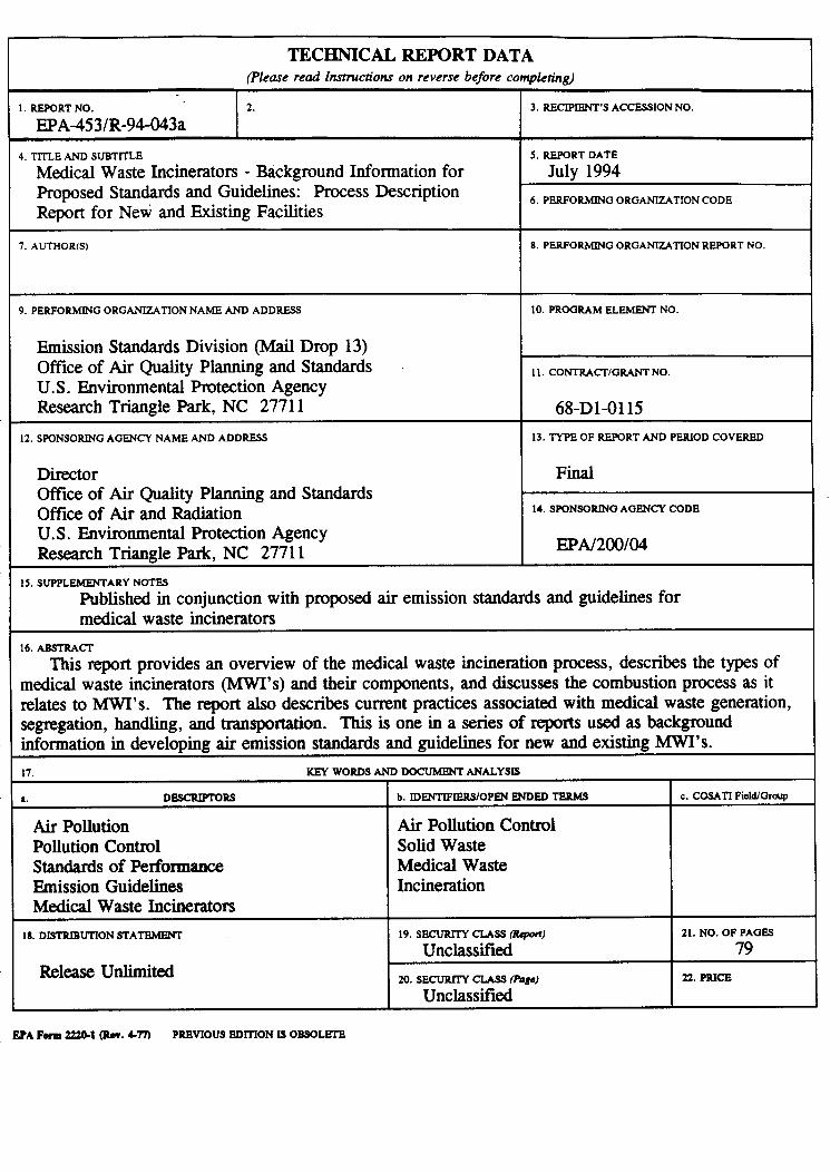
TECHNICAL REPORT DATA
I
I 17. KEY WORDS AND DOCUMWT ANALYSIS
1. REPORT NO. I EpA-453/R-94-043a 4. TITLE AND SUBTlTLE
Medical Waste Incinerators - Background Information for Proposed Standards and Guidelines: Process Description Report for New and Existing Facilities
7. AUTHOR(S)
9. PERFORMING ORGANIZATION NAME AND ADDRESS r Emission Standards Division (Mail Drop 13) Office of Air Quality Planning and Standards U.S. Environmental Protection Agency Research Triangle Park, NC 27711
12. SPONSORING AGENCY NAME AND ADDRESS r
3. RECIPIENT’S ACCESSION NO.
5. REPORT DATE
July 1994 6. PERFORMING ORGANIZATION CODE
8 . PERFORMING ORGANIZATION REPORT NO.
10. PROGRAM ELEh4ENT NO.
11. CONTRAffTIGRANT NO.
68-D1-0115 13. TYPE OF REPORT AND PERIOD COVERED
Final Director Office of Air Quality Planning and Standards Office of Air and Radiation U.S. Environmental Protection Agency Research Triangle Park, NC 27711
1s. SUPPLEMENTARY NOTES
Published in conjunction with proposed air emission standards and guidelines for medical waste incinerators
16. ABSTRAff
This report provides an overview of the medical waste incineration process, describes the types of medical waste incinerators ( M W I ’ s ) and their components, and discusses the combustion process as it relates to MWI’s. The report also describes cumnt practices associated with medical waste generation, segregation, handling, and transportation. This is one in a series of reports used as background information in developing air emission standards and guidelines for new and existing MWI’s.
a. DBSCRIPTORS
Air Pollution Pollution Control Standards of Perfomance Emission Guidelines Medical Waste Incinerators
la. DISTRIBUTION STATEMENT
I Rel-unlimited I
14. SPONSORIN0 AOENCY CODE
EPA/200/04
b. IDENTIFIERSlOPW ENDED TBRMS
Air Pollution Control Solid Waste Medical Waste Incineration
19. SECURllT CUSS (Rqwt)
Unclassified 20. S m C U S S (Aage)
Unclassified
21. NO. OF PAGES
79 22. PRICE
EPA Form 22241 (Rev. Cn) PREVIOUS EDITTON IS OBSOLEIZ