medium-voltage distribution - 24 kv metal-enclosed ... · metal-enclosed withdrawable switchgears....
TRANSCRIPT
Medium-Voltage distribution - 24 kV Metal-enclosed withdrawable switchgears • MCset4 - SF6 technology • NEX24 - vacuum technology
2008 Maintenance and Services Guide October 2008
PE
9000
2

24 kVA brief summary of the
range
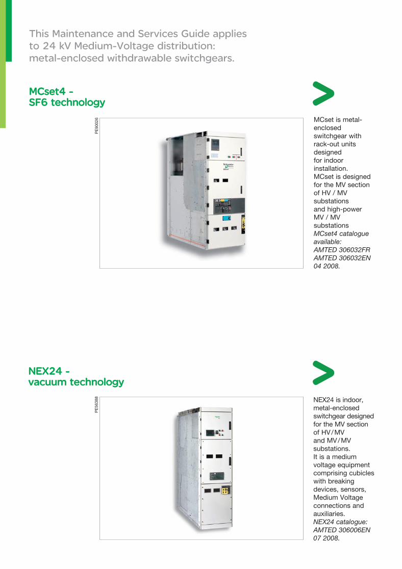
This Maintenance and Services Guide applies to 24 kV Medium-Voltage distribution: metal-enclosed withdrawable switchgears.
MCset is metal-enclosed switchgear with rack-out units designed for indoor installation. MCset is designed for the MV section of HV / MV substations and high-power MV / MV substationsMCset4 catalogue available: AMTED 306032FR AMTED 306032EN 04 2008.
NEX24 is indoor, metal-enclosed switchgear designed for the MV section of HV / MV and MV / MV substations. It is a medium voltage equipment comprising cubicles with breaking devices, sensors, Medium Voltage connections and auxiliaries.NEX24 catalogue: AMTED 306006EN 07 2008.
NEX24 - NEX24 - vacuum technologyvacuum technology
MCset4 - MCset4 - SF6 technology SF6 technology
PE
9002
6P
E56
388
24 kVMaintenanceand Services GuideMV Distribution
Distribution
3
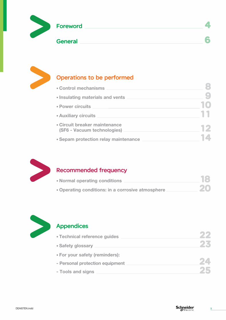
Recommended frequency Recommended frequency
• Normal operating conditions
• Operating conditions: in a corrosive atmosphere
18182020
Appendices Appendices
• Technical reference guides
• Safety glossary
• For your safety (reminders):
- Personal protection equipment
- Tools and signs
22222323
24242525
Foreword Foreword
General General
4
6
• Control mechanisms
• Insulating materials and vents
• Power circuits
• Auxiliary circuits
• Circuit breaker maintenance (SF6 - Vacuum technologies)
• Sepam protection relay maintenance
89
10101111
12121414
Operations to be performed Operations to be performed
DEAI07EN.indd

PE
9000
8
Foreword
Maintenance and Services Guide Medium-Voltage distribution - 24 kV
Electrical equipment may only be maintained by qualified engineers. Schneider Electric accepts no responsibility for the consequences that may result from the use of this document.
Maintenance of the equipment: responsibility Maintenance of the equipment: responsibility
The user is responsible for checking that the equipment ratings are appropriate for its intended use. You must read the operating and installation instructions prior to commissioning or maintenance and comply with them. Failure to comply with these requirements may affect the correct operation of the equipment and constitute a hazard for the workforce and the equipment.
Operation of the equipment: user’s responsibility Operation of the equipment: user’s responsibility
The user is responsible for conforming to all the standards and international and national electrical codes in force regarding the protective earthing of all the equipment.
Protective earthing Protective earthing
Your Maintenance and Services Guide contains general instructions for: • reducing equipment wear and tear (and / or failure), • ensuring that the equipment is safe during all installation, repair and servicing operations.
5DEAI07EN.indd
Warning As Medium-Voltage devices fulfil safety functions, they must be installed in accordance with certain professional practices. Similarly, preventive maintenance operations must be strictly and regularly observed.
6
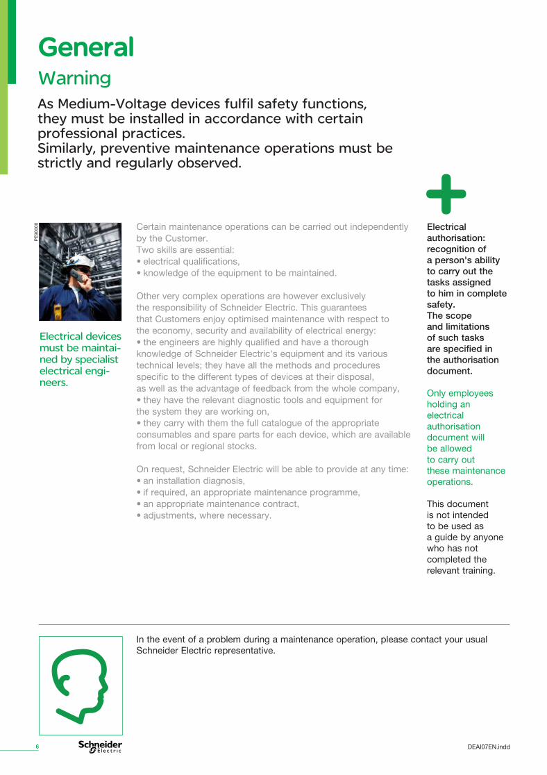
Certain maintenance operations can be carried out independently by the Customer. Two skills are essential: • electrical qualifications, • knowledge of the equipment to be maintained.
Other very complex operations are however exclusively the responsibility of Schneider Electric. This guarantees that Customers enjoy optimised maintenance with respect to the economy, security and availability of electrical energy: • the engineers are highly qualified and have a thorough knowledge of Schneider Electric's equipment and its various technical levels; they have all the methods and procedures specific to the different types of devices at their disposal, as well as the advantage of feedback from the whole company, • they have the relevant diagnostic tools and equipment for the system they are working on, • they carry with them the full catalogue of the appropriate consumables and spare parts for each device, which are available from local or regional stocks.
On request, Schneider Electric will be able to provide at any time: • an installation diagnosis, • if required, an appropriate maintenance programme, • an appropriate maintenance contract, • adjustments, where necessary.
Electrical devices must be maintai-ned by specialist electrical engi-neers.
General General
Electrical authorisation: recognition of a person's ability to carry out the tasks assigned to him in complete safety. The scope and limitations of such tasks are specified in the authorisation document.
Only employees holding an electrical authorisation document will be allowed to carry out these maintenance operations.
This document is not intended to be used as a guide by anyone who has not completed the relevant training.
PE
9000
0
In the event of a problem during a maintenance operation, please contact your usual Schneider Electric representative.
DEAI07EN.indd
Intervention levels Different skill levels have been established to define the persons who are competent to work on Medium-Voltage equipment. The five intervention levels developed follow the life cycle of the equipment, whilst at the same time defining the levels of complexity.
7
Regular maintenance. The maintenance operations to be carried out on the equipment are generally described in the instruction handbook. They include minor preventive maintenance operations not requiring the removal of any parts of the equipment and servicing by replacement with standard parts provided for this purpose, carried out by a technician authorised to do so by the user, according to the manufacturer's maintenance instructions.
Operations requiring simple procedures and / or support equipment (integrated into devices or external) that is easy to use and implement.
Preventive maintenance operations, such as general adjustment, identification and troubleshooting, repairs by exchanging components or functional units, minor mechanical repairs carried out by a specialised technician using the tools and adjusting and measuring instruments specified in the manufacturer's maintenance instructions.
Operations whose procedures involve knowledge of a specific technique or technology and / or the use of specialised support equipment. All important corrective or preventive maintenance operations carried out by the manufacturer's after-sales services. Operations that may affect switchgear performance.
Operations whose procedures involve know-how requiring the use of particular techniques or technologies, industrial processes or support equipment. Equipment will generally have to be returned to the factory. This applies only to moving parts.
Training Schneider Electric offers a wide choice of training courses on how to operate or maintain its equipment. Level 3-4-5 operations require training on the equipment.
Training programme This training is delivered in our training centres by Schneider Electric's accredited qualified staff.
Level 1
2Level
3Level
4Level
5Level
Formation
DEAI07EN.indd
Operations to be performedOperations to be performed
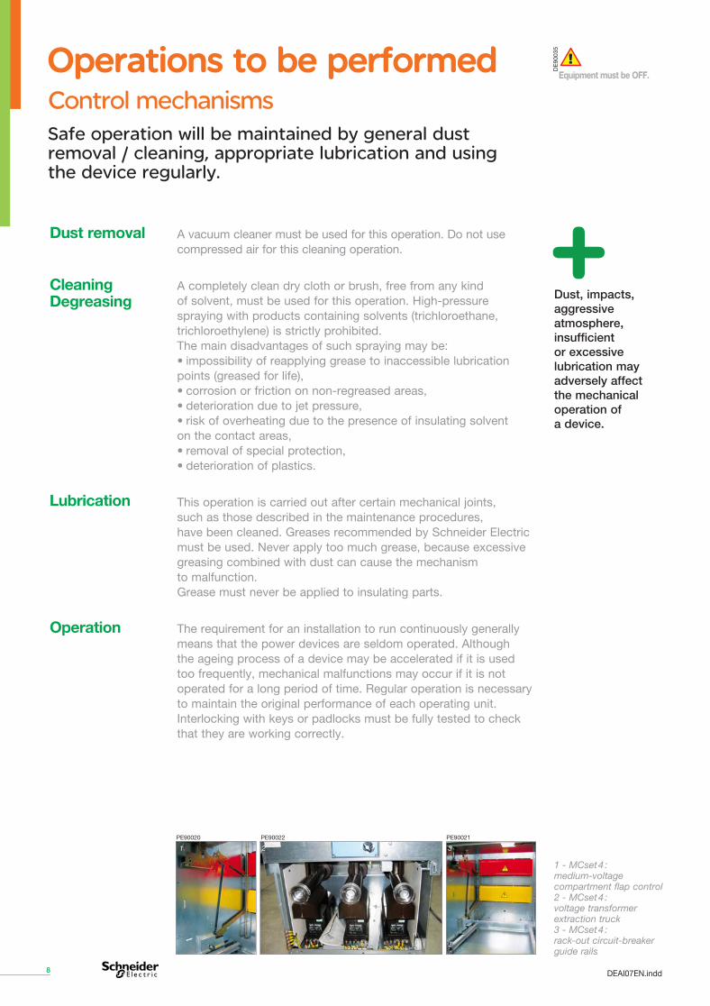
1 - MCset 4 : medium-voltage compartment flap control 2 - MCset 4 : voltage transformer extraction truck 3 - MCset 4 : rack-out circuit-breaker guide rails
1 2 3
8
Dust removal A vacuum cleaner must be used for this operation. Do not use compressed air for this cleaning operation.
A completely clean dry cloth or brush, free from any kind of solvent, must be used for this operation. High-pressure spraying with products containing solvents (trichloroethane, trichloroethylene) is strictly prohibited. The main disadvantages of such spraying may be: • impossibility of reapplying grease to inaccessible lubrication points (greased for life), • corrosion or friction on non-regreased areas, • deterioration due to jet pressure, • risk of overheating due to the presence of insulating solvent on the contact areas, • removal of special protection, • deterioration of plastics.
This operation is carried out after certain mechanical joints, such as those described in the maintenance procedures, have been cleaned. Greases recommended by Schneider Electric must be used. Never apply too much grease, because excessive greasing combined with dust can cause the mechanism to malfunction. Grease must never be applied to insulating parts.
The requirement for an installation to run continuously generally means that the power devices are seldom operated. Although the ageing process of a device may be accelerated if it is used too frequently, mechanical malfunctions may occur if it is not operated for a long period of time. Regular operation is necessary to maintain the original performance of each operating unit. Interlocking with keys or padlocks must be fully tested to check that they are working correctly.
Operation
Lubrication
Cleaning Degreasing Dust, impacts,
aggressive atmosphere, insufficient or excessive lubrication may adversely affect the mechanical operation of a device.
PE90021PE90022PE90020
Equipment must be OFF.
DE
9003
5
Control mechanismsSafe operation will be maintained by general dust removal / cleaning, appropriate lubrication and using the device regularly.
DEAI07EN.indd
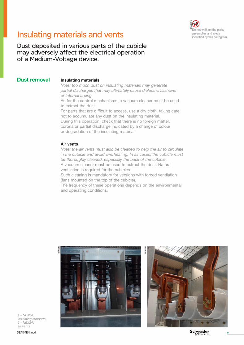
Insulating materials and vents
Insulating materials Note: too much dust on insulating materials may generate partial discharges that may ultimately cause dielectric flashover or internal arcing. As for the control mechanisms, a vacuum cleaner must be used to extract the dust. For parts that are difficult to access, use a dry cloth, taking care not to accumulate any dust on the insulating material. During this operation, check that there is no foreign matter, corona or partial discharge indicated by a change of colour or degradation of the insulating material.
Air vents Note: the air vents must also be cleaned to help the air to circulate in the cubicle and avoid overheating. In all cases, the cubicle must be thoroughly cleaned, especially the back of the cubicle. A vacuum cleaner must be used to extract the dust. Natural ventilation is required for the cubicles. Such cleaning is mandatory for versions with forced ventilation (fans mounted on the top of the cubicle). The frequency of these operations depends on the environmental and operating conditions.
1
1 - NEX24 : insulating supports 2 - NEX24 : air vents
9
Dust removal
2
PE
9001
6
PE
9001
7
DE
9003
6
Do not walk on the parts, assemblies and areas identified by this pictogram.
Dust deposited in various parts of the cubicle may adversely affect the electrical operation of a Medium-Voltage device.
DEAI07EN.indd
Power circuits
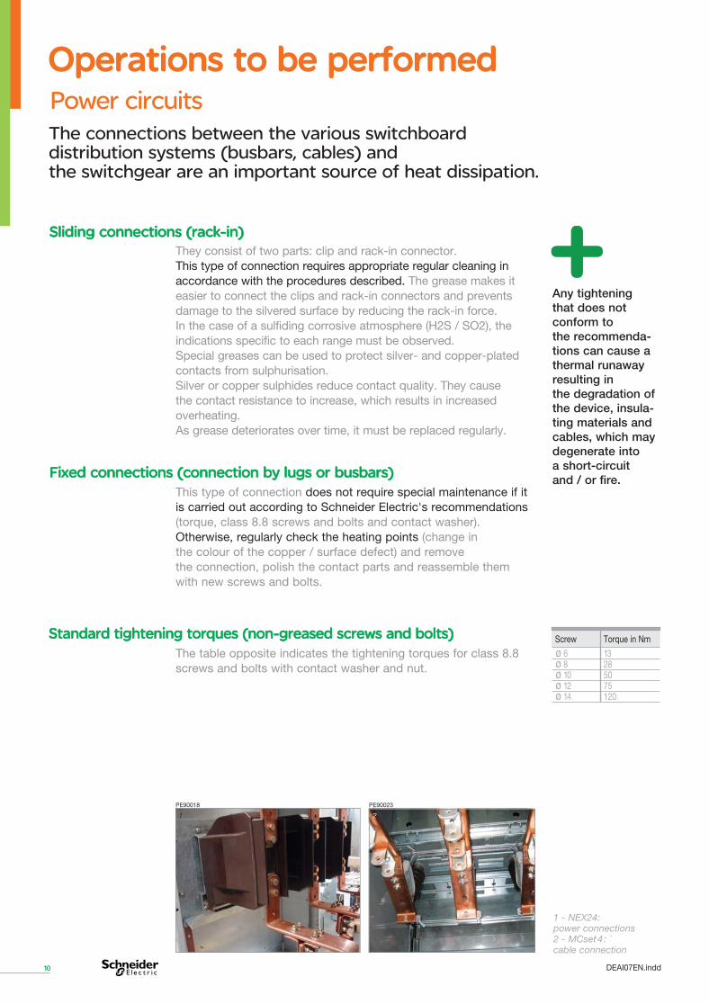
1 - NEX24: power connections 2 - MCset 4 : `cable connection
1 2
Screw Torque in Nm
ø 6 13 ø 8 28 ø 10 50 ø 12 75 ø 14 120
10
Operations to be performedOperations to be performed
They consist of two parts: clip and rack-in connector. This type of connection requires appropriate regular cleaning in accordance with the procedures described. The grease makes it easier to connect the clips and rack-in connectors and prevents damage to the silvered surface by reducing the rack-in force. In the case of a sulfiding corrosive atmosphere (H2S / SO2), the indications specific to each range must be observed. Special greases can be used to protect silver- and copper-plated contacts from sulphurisation. Silver or copper sulphides reduce contact quality. They cause the contact resistance to increase, which results in increased overheating. As grease deteriorates over time, it must be replaced regularly.
Sliding connections (rack-in)Sliding connections (rack-in)
Fixed connections (connection by lugs or busbars) Fixed connections (connection by lugs or busbars) This type of connection does not require special maintenance if it is carried out according to Schneider Electric's recommendations (torque, class 8.8 screws and bolts and contact washer). Otherwise, regularly check the heating points (change in the colour of the copper / surface defect) and remove the connection, polish the contact parts and reassemble them with new screws and bolts.
The table opposite indicates the tightening torques for class 8.8 screws and bolts with contact washer and nut.
Standard tightening torques (non-greased screws and bolts) Standard tightening torques (non-greased screws and bolts)
Any tightening that does not conform to the recommenda-tions can cause a thermal runaway resulting in the degradation of the device, insula-ting materials and cables, which may degenerate into a short-circuit and / or fire.
PE90018 PE90023
The connections between the various switchboard distribution systems (busbars, cables) and the switchgear are an important source of heat dissipation.
DEAI07EN.indd
Low-Voltage auxiliary circuits
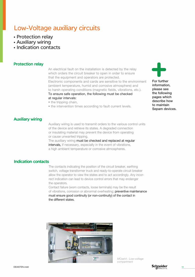
MCset 4 : Low-voltage compartment
11
Auxiliary wiring is used to transmit orders to the various control units of the device and retrieve its states. A degraded connection or insulating material may prevent the device from operating or cause unwanted tripping. The auxiliary wiring must be checked and replaced at regular intervals, if necessary, especially in the event of vibrations, a high ambient temperature or corrosive atmospheres.
Auxiliary wiring Auxiliary wiring
The contacts indicating the position of the circuit breaker, earthing switch, voltage transformer truck and ready-to-operate circuit breaker allow the operator to view the states and to act accordingly. Any incor-rect indication can lead to device control errors that may endanger the operators. Contact failure (worn contacts, loose terminals) may be the result of vibrations, corrosion or abnormal overheating; preventive maintenance must ensure good continuity (or non-continuity) of the contact in the different states.
Indication contacts Indication contacts
An electrical fault on the installation is detected by the relay which orders the circuit breaker to open in order to ensure that the equipment and operators are protected. Electronic components and cards are sensitive to the environment (ambient temperature, humid and corrosive atmosphere) and to harsh operating conditions (magnetic fields, vibrations, etc.). To ensure safe operation, the following must be checked at regular intervals: • the tripping chain, • the intervention times according to fault current levels.
Protection relay Protection relay
For further information, please see the following pages which describe how to maintain Sepam devices.
PE
9002
4
• Protection relay • Auxiliary wiring • Indication contacts
DEAI07EN.indd
Operations to be performed Operations to be performed Circuit breaker maintenance
The internal pressure of the circuit breakers must only be checked in the event of an SF6 alarm and such checks must be performed by Schneider Electric's specialist engineers. The SF6 circuit breaker is classed as a sealed system. When it is manufactured, the leakage rate of each enclosure is measured. We can therefore be sure that the leakage rate is less than the loss specified in the standard. If an SF6 pressure drop is indicated, you are advised to remove the circuit breaker from service and call in Schneider Electric to diagnose the fault in the malfunctioning device.
Checking the internal pressure of the circuit breakers Checking the internal pressure of the circuit breakers
Circuit breaker maintenance operations such as visual checks, cleaning with a degreasing agent, removal / replacement, checking for wear, dust removal, etc. are detailed and explained in the technical reference guides at your disposal.
The operations are carried out on the pole enclosure, the control parts (springs, control unit, latching mechanism, gear motor) and the pole mechanism.
The pressurised SF6 gas inside the poles retains all its dielectric properties after breaking. Electrical endurance is limited by contact wear. Contact wear depends on how much the device is used. We wish to draw your attention to the dangers of using a cleaning process that involves spraying solvents at high pressure. The main disadvantages of such a process are as follows: • damage due to jet pressure and impossibility of relubricating inaccessible fixing points, • risk of overheating due to solvent pressure in contact areas, • removal of special protection. A dry cloth must be used for cleaning.
Pole maintenance Pole maintenance
Insulating parts must be cleaned with a soft, dry, lint-free cloth.
Cleaning processes that involve spraying a pressurised insulating solvent and using degreaser aerosols are absolutely forbidden.
The parts must be cleaned to remove the old grease before new grease is applied. An electrical or mechanical solvent cleaner must be used for cleaning, depending on the part to be cleaned.
Important
12
A circuit breaker is a safety device used to operate and protect electrical distribution networks. It is fitted in a cubicle to protect all the downstream components in the event of a short-circuit.
DEAI07EN.indd
Rack-out circuit breaker with SF6 technology
13
Circuit breaker maintenance
DEAI07EN.indd
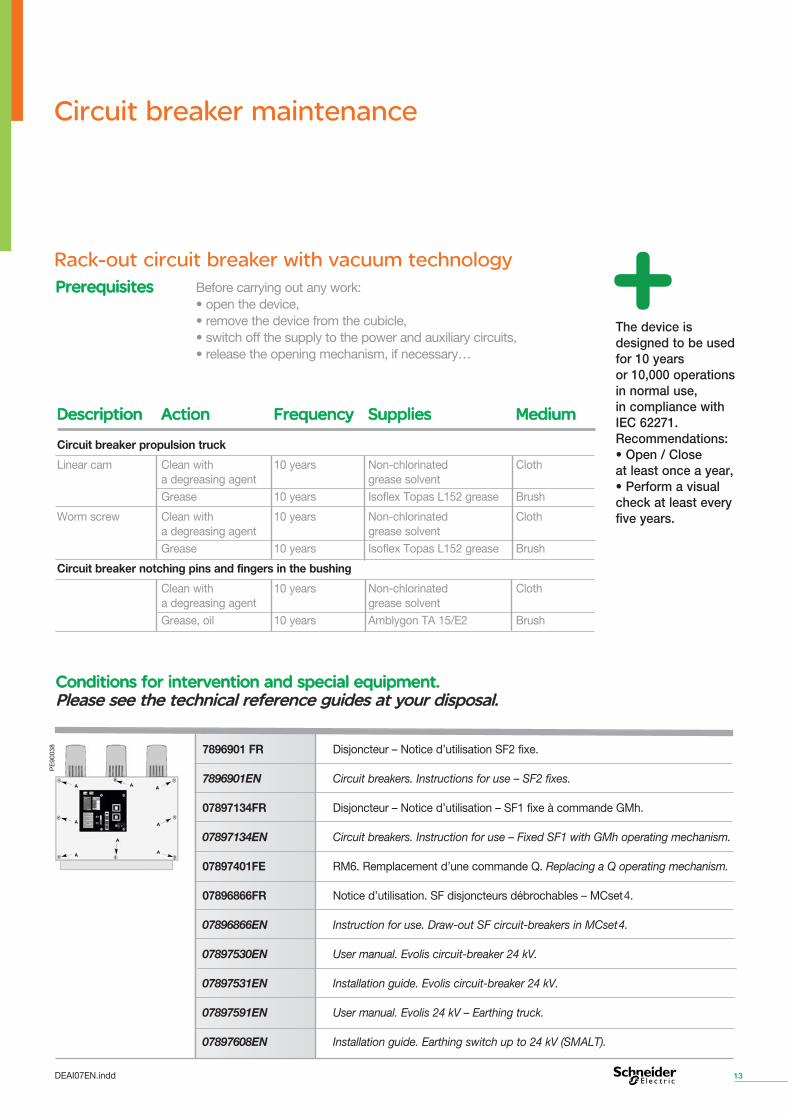
Rack-out circuit breaker with vacuum technology Before carrying out any work: • open the device, • remove the device from the cubicle, • switch off the supply to the power and auxiliary circuits, • release the opening mechanism, if necessary…
Prerequisites Prerequisites
The device is designed to be used for 10 years or 10,000 operations in normal use, in compliance with IEC 62271. Recommendations: • Open / Close at least once a year, • Perform a visual check at least every five years.
Conditions for intervention and special equipment. Conditions for intervention and special equipment. Please see the technical reference guides at your disposal. Please see the technical reference guides at your disposal.
7896901 FR Disjoncteur – Notice d’utilisation SF2 fixe.
7896901EN Circuit breakers. Instructions for use – SF2 fixes.
07897134FR Disjoncteur – Notice d’utilisation – SF1 fixe à commande GMh.
07897134EN Circuit breakers. Instruction for use – Fixed SF1 with GMh operating mechanism.
07897401FE RM6. Remplacement d’une commande Q. Replacing a Q operating mechanism.
07896866FR Notice d’utilisation. SF disjoncteurs débrochables – MCset 4.
07896866EN Instruction for use. Draw-out SF circuit-breakers in MCset 4.
07897530EN User manual. Evolis circuit-breaker 24 kV.
07897531EN Installation guide. Evolis circuit-breaker 24 kV.
07897591EN User manual. Evolis 24 kV – Earthing truck.
07897608EN Installation guide. Earthing switch up to 24 kV (SMALT).
PE
9003
8
Descriptionescription ActionAction FrequencyFrequency Supplies Supplies MediumMedium
Circuit breaker propulsion truck
Linear cam Clean with 10 years Non-chlorinated Cloth a degreasing agent grease solvent Grease 10 years Isoflex Topas L152 grease Brush
Worm screw Clean with 10 years Non-chlorinated Cloth a degreasing agent grease solvent Grease 10 years Isoflex Topas L152 grease Brush
Circuit breaker notching pins and fingers in the bushing
Clean with 10 years Non-chlorinated Cloth a degreasing agent grease solvent Grease, oil 10 years Amblygon TA 15/E2 Brush
14
Operations to be performed Operations to be performed Sepam protection relay maintenance
• Only qualified operators familiar with all the installation instructions are authorised to work on the facility.
• Switch off all power supplies before working on this equipment.
• Always use an appropriate voltage detection device to check that the power supply is off.
• Before carrying out visual checks, tests or maintenance operations, disconnect all current and voltage sources. Start from the principle that all the systems are powered on until they have been completely powered off, tested and labelled. Pay particular attention to the design of the power circuit. Take account of all the power supply sources and, in particular, any possible power supplies outside the cubicle in which the equipment is installed.
• Handling this product requires the appropriate skills related to the protection of electrical networks. Only engineers with the relevant skills are authorised to configure and adjust this product.
• Before carrying out a dielectric strength test or an insulation test on the cubicle in which the Sepam is installed, disconnect all the Sepam connection wires. High-voltage tests may damage the electronic components.
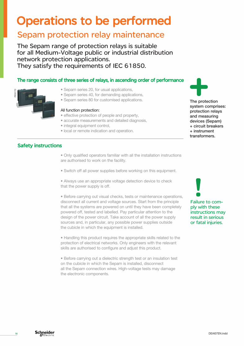
The protection system comprises: protection relays and measuring devices (Sepam) + circuit breakers + instrument transformers.
The Sepam range of protection relays is suitable for all Medium-Voltage public or industrial distribution network protection applications. They satisfy the requirements of IEC 61850.
• Sepam series 20, for usual applications, • Sepam series 40, for demanding applications, • Sepam series 80 for customised applications.
All function protection: • effective protection of people and property, • accurate measurements and detailed diagnosis, • integral equipment control, • local or remote indication and operation.
The range consists of three series of relays, in ascending order of performanceThe range consists of three series of relays, in ascending order of performance
PE
5517
0
Safety instructions Safety instructions
Failure to com-ply with these instructions may result in serious or fatal injuries.
DEAI07EN.indd
15
The logic inputs and outputs and analogue inputs are the parts of Sepam that are the least well covered by the self-tests. They should be tested during a maintenance operation. It is recommended that preventive maintenance be carried out every five years. For the list of Sepam self-tests, please refer to the operating instructions and technical reference guides at your disposal.
General General
Sepam protection relay maintenance
Carry out all the commissioning tests recommended for the type of Sepam to be tested, apart from the test specific to the earth leakage protection function, which is not necessary. Depending on the module installed, voltage input tests may be required. Give priority to testing the logic inputs and outputs which are involved in tripping the circuit breaker. Testing the complete system which includes the circuit breaker is also recommended. For information on how to maintain Sepam devices, see the “Commissioning” chapters in the available technical reference guides.
Maintenance tests Maintenance tests
Risk of damaging the Sepam • do not open the Sepam base unit, • do not attempt to repair Sepam components, the base unit or accessories.
Failure to comply with these instructions may damage the equipment.
Important
Repairs by replacement: when the Sepam or a module is deemed to be faulty, replace it with a new product or module, as these items cannot be repaired.
DEAI07EN.indd
16
Operations to be performed Operations to be performed Sepam protection relay maintenance
Sepam is in the fallback position. The failures detected are considered to be major faults.
MAJOR fault MAJOR fault
Sepam is not working properly. The base unit is working (all the protection devices activated are operating) and indicates that one of the optional modules is faulty, or that a module is configured but not connected.
MINOR faultMINOR faultMajor faults are only cleared after the cause of the fault is corrected and Sepam is switched on again.
PE
5035
9
Fault message on display: major fault.
PE
1013
9
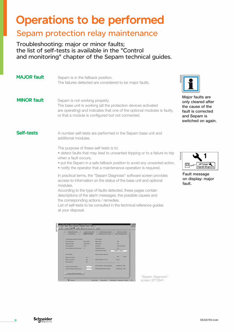
A number self-tests are performed in the Sepam base unit and additional modules.
The purpose of these self-tests is to: • detect faults that may lead to unwanted tripping or to a failure to trip when a fault occurs, • put the Sepam in a safe fallback position to avoid any unwanted action, • notify the operator that a maintenance operation is required.
In practical terms, the “Sepam Diagnosis” software screen provides access to information on the status of the base unit and optional modules. According to the type of faults detected, these pages contain descriptions of the alarm messages, the possible causes and the corresponding actions / remedies. List of self-tests to be consulted in the technical reference guides at your disposal.
Self-tests Self-tests
“Sepam Diagnosis” screen SFT2841.
MT1
0848
DEAI07EN.indd
Troubleshooting: major or minor faults; the list of self-tests is available in the "Control and monitoring" chapter of the Sepam technical guides.
17
Sepam protection relay maintenance
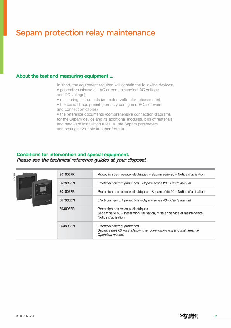
In short, the equipment required will contain the following devices: • generators (sinusoidal AC current, sinusoidal AC voltage and DC voltage), • measuring instruments (ammeter, voltmeter, phasemeter), • the basic IT equipment (correctly configured PC, software and connection cables), • the reference documents (comprehensive connection diagrams for the Sepam device and its additional modules, bills of materials and hardware installation rules, all the Sepam parameters and settings available in paper format).
About the test and measuring equipment … About the test and measuring equipment …
Conditions for intervention and special equipment.Conditions for intervention and special equipment. Please see the technical reference guides at your disposal.Please see the technical reference guides at your disposal.
301005FR Protection des réseaux électriques – Sepam série 20 – Notice d’utilisation.
301005EN Electrical network protection – Sepam series 20 – User’s manual.
301006FR Protection des réseaux électriques – Sepam série 40 – Notice d’utilisation.
301006EN Electrical network protection – Sepam series 40 – User’s manual.
303003FR Protection des réseaux électriques. Sepam série 80 – Installation, utilisation, mise en service et maintenance. Notice d’utilisation.
303003EN Electrical network protection. Sepam series 80 – Installation, use, commissionning and maintenance. Operation manual.
MT5
0298
DEAI07EN.indd
18
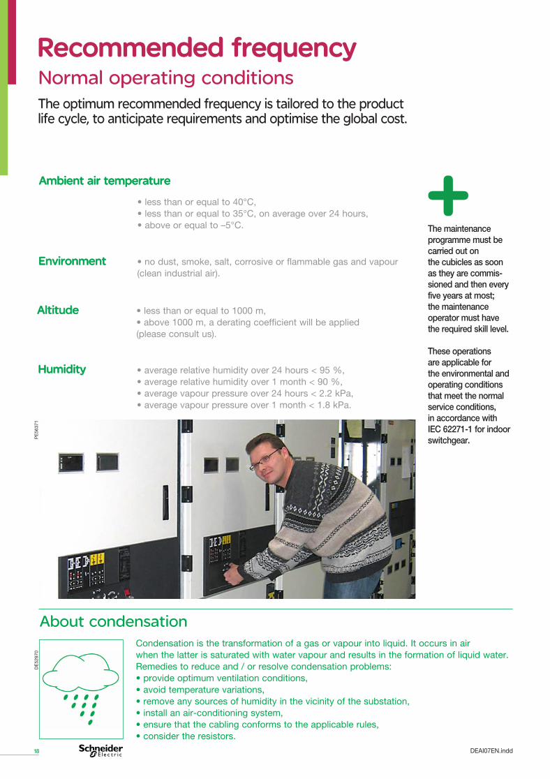
Recommended frequency Recommended frequency
Normal operating conditions
The maintenance programme must be carried out on the cubicles as soon as they are commis-sioned and then every five years at most; the maintenance operator must have the required skill level.
These operations are applicable for the environmental and operating conditions that meet the normal service conditions,in accordance with IEC 62271-1 for indoor switchgear.
HumidityHumidity • average relative humidity over 24 hours < 95 %, • average relative humidity over 1 month < 90 %, • average vapour pressure over 24 hours < 2.2 kPa, • average vapour pressure over 1 month < 1.8 kPa.
• less than or equal to 40°C, • less than or equal to 35°C, on average over 24 hours, • above or equal to –5°C.
Ambient air temperature Ambient air temperature
• less than or equal to 1000 m, • above 1000 m, a derating coefficient will be applied (please consult us).
AltitudeAltitude
• no dust, smoke, salt, corrosive or flammable gas and vapour (clean industrial air).
Environment Environment
Condensation is the transformation of a gas or vapour into liquid. It occurs in air when the latter is saturated with water vapour and results in the formation of liquid water. Remedies to reduce and / or resolve condensation problems: • provide optimum ventilation conditions, • avoid temperature variations, • remove any sources of humidity in the vicinity of the substation, • install an air-conditioning system, • ensure that the cabling conforms to the applicable rules, • consider the resistors.
About condensation
PE
5637
1D
E52
970
The optimum recommended frequency is tailored to the product life cycle, to anticipate requirements and optimise the global cost.
DEAI07EN.indd
19
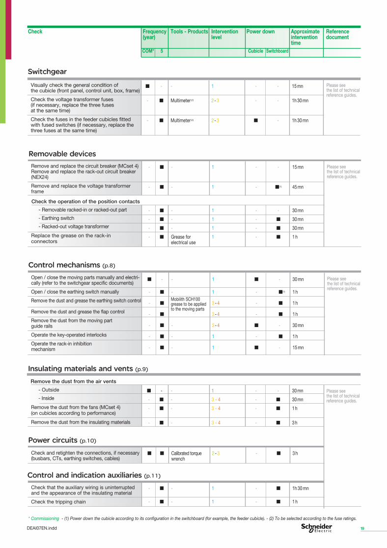
Please see the list of technical reference guides.
* Commissioning - (1) Power down the cubicle according to its configuration in the switchboard (for example, the feeder cubicle). - (2) To be selected according to the fuse ratings.
■ - - 1 - - 15 mn
- ■ Multimeter (2) 2 - 3 - - 1h 30 mn
- ■ Multimeter (2) 2 - 3 ■ - 1h 30 mn
Switchgear Switchgear
Visually check the general condition of the cubicle (front panel, control unit, box, frame)
Check the voltage transformer fuses (if necessary, replace the three fuses at the same time)
Check the fuses in the feeder cubicles fitted with fused switches (if necessary, replace the three fuses at the same time)
Please see the list of technical reference guides.
Remove and replace the circuit breaker (MCset 4) Remove and replace the rack-out circuit breaker (NEX24)
Remove and replace the voltage transformer frame
- ■ - 1 - - 15 mn
- ■ - 1 - ■(1) 45 mn
- Removable racked-in or racked-out part
- Earthing switch
- Racked-out voltage transformer
Replace the grease on the rack-in connectors
- ■ - 1 - - 30 mn
- ■ - 1 - ■ 30 mn
- ■ - 1 - ■ 30 mn
- ■ Grease for 1 - ■ 1 h electrical use
Check the operation of the position contacts
Removable devices Removable devices
Please see the list of technical reference guides.
Open / close the moving parts manually and electri-cally (refer to the switchgear specific documents)
Open / close the earthing switch manually
Remove the dust and grease the earthing switch control
Remove the dust and grease the flap control
Remove the dust from the moving part guide rails
Operate the key-operated interlocks
Operate the rack-in inhibition mechanism
■ - - 1 ■ - 30 mn - ■ - 1 - ■(1) 1 h
- ■ 3 - 4 - ■ 1 h
- ■ 3 - 4 - ■ 1 h
- ■ - 3 - 4 ■ - 30 mn
- ■ - 1 - ■ 1 h
- ■ - 1 ■ - 15 mn
Mobilith SCH100 grease to be applied to the moving parts
Control mechanisms Control mechanisms (p.8)
Please see the list of technical reference guides.
- Outside
- Inside
Remove the dust from the fans (MCset 4) (on cubicles according to performance)
Remove the dust from the insulating materials
■ - - 1 - - 30 mn
- ■ - 3 - 4 - ■ 30 mn
- ■ - 3 - 4 - ■ 1 h
- ■ - 3 - 4 - ■ 3 h
Remove the dust from the air vents
Insulating materials and vents Insulating materials and vents (p.9)
Check and retighten the connections, if necessary (busbars, CTs, earthing switches, cables)
■ ■ Calibrated torque 2 - 3 - ■ 3 h wrench
Power circuits Power circuits (p.10)
Check that the auxiliary wiring is uninterrupted and the appearance of the insulating material
Check the tripping chain
- ■ - 1 - ■ 1h 30 mn
- ■ - 1 - ■ 1 h
Control and indication auxiliaries Control and indication auxiliaries (p.11)
DEAI07EN.indd
Check Frequency Tools - Products Intervention Power down Approximate Reference (year) level intervention document time
COM* 5 Cubicle Switchboard
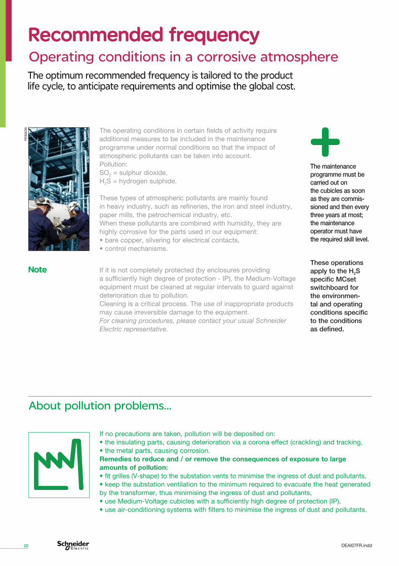
The operating conditions in certain fields of activity require additional measures to be included in the maintenance programme under normal conditions so that the impact of atmospheric pollutants can be taken into account. Pollution: SO2 = sulphur dioxide, H2S = hydrogen sulphide.
These types of atmospheric pollutants are mainly found in heavy industry, such as refineries, the iron and steel industry, paper mills, the petrochemical industry, etc. When these pollutants are combined with humidity, they are highly corrosive for the parts used in our equipment: • bare copper, silvering for electrical contacts, • control mechanisms.
Operating conditions in a corrosive atmosphere
20
Recommended frequencyRecommended frequency
If no precautions are taken, pollution will be deposited on: • the insulating parts, causing deterioration via a corona effect (crackling) and tracking, • the metal parts, causing corrosion. Remedies to reduce and / or remove the consequences of exposure to large amounts of pollution: • fit grilles (V-shape) to the substation vents to minimise the ingress of dust and pollutants, • keep the substation ventilation to the minimum required to evacuate the heat generated by the transformer, thus minimising the ingress of dust and pollutants, • use Medium-Voltage cubicles with a sufficiently high degree of protection (IP), • use air-conditioning systems with filters to minimise the ingress of dust and pollutants.
About pollution problems...
The maintenance programme must be carried out on the cubicles as soon as they are commis-sioned and then every three years at most; the maintenance operator must have the required skill level.
These operations apply to the H2S specific MCset switchboard for the environmen-tal and operating conditions specific to the conditions as defined.
If it is not completely protected (by enclosures providing a sufficiently high degree of protection - IP), the Medium-Voltage equipment must be cleaned at regular intervals to guard against deterioration due to pollution. Cleaning is a critical process. The use of inappropriate products may cause irreversible damage to the equipment. For cleaning procedures, please contact your usual Schneider Electric representative.
NoteNote
PE
9003
6
The optimum recommended frequency is tailored to the product life cycle, to anticipate requirements and optimise the global cost.
DEAI07FR.indd

Check that the auxiliary wiring is uninterrupted and the appearance of the insulating material
Check the tripping chain
- ■ - 1 - ■ 1h 30 mn
- ■ - 1 - ■ 1 h
Control and indication auxiliaries Control and indication auxiliaries (p.11)
Insulating materials and vents Insulating materials and vents (p.9)
- Outside
- Inside
Remove the dust from the fans (MCset 4) (on cubicles according to performance)
Remove the dust from the insulating materials
■ - - 1 - - 30 mn
- ■ - 3 - 4 - ■ 30 mn
- ■ - 3 - 4 - ■ 1 h
- ■ - 3 - 4 - ■ 3 h
Remove the dust from the air vents
Check and retighten the connections, if necessary (busbars, CTs, earthing switches, cables)
■ ■ Calibrated torque 2 - 3 - ■ 3 h wrench
Power circuits Power circuits (p.10)
21
■ - - 1 - - 15 mn
- ■ Multimeter (2) 2 - 3 - - 1h 30 mn
- ■ Multimeter (2) 2 - 3 ■ - 1h 30 mn
SwitchgearSwitchgear
Visually check the general condition of the cubicle (front panel, control unit, box, frame)
Check the voltage transformer fuses (if necessary, replace the three fuses at the same time)
Check the fuses in the feeder cubicles fitted with fused switches (if necessary, replace the three fuses at the same time)
Please see the list of technical reference guides.
Open / close the moving parts manually and electri-cally (refer to the switchgear specific documents)
Open / close the earthing switch manually
Remove the dust and grease the earthing switch control
Remove the dust and grease the flap control
Remove the dust from the moving part guide rails
Operate the key-operated interlocks
Operate the rack-in inhibition mechanism
■ - - 1 ■ - 30 mn - ■ - 1 - ■(1) 1 h
- ■ 3 - 4 - ■ 1 h
- ■ 3 - 4 - ■ 1 h
- ■ - 3 - 4 ■ - 30 mn
- ■ - 1 - ■ 1 h
- ■ - 1 ■ - 15 mn
Control mechanisms Control mechanisms (p.8)
Mobilith SCH100 grease to be applied to the moving parts
Please see the list of technical reference guides.
* Commissioning - (1) Power down the cubicle according to its configuration in the switchboard (for example, the feeder cubicle). - (2) To be selected according to the fuse ratings.
Please see the list of technical reference guides.
Remove and replace the circuit breaker (MCset 4) Remove and replace the rack-out circuit breaker (NEX24)
Remove and replace the voltage transformer frame
- ■ - 1 - - 15 mn
- ■ - 1 - ■(1) 45 mn
- Removable racked-in or racked-out part
- Earthing switch
- Racked-out voltage transformer
Replace the grease on the rack-in connectors
- ■ - 1 - - 30 mn
- ■ - 1 - ■ 30 mn
- ■ - 1 - ■ 30 mn
- ■ Grease for 1 - ■ 1 h electrical use
Check the operation of the position contacts
Removable devices Removable devices
Please see the list of technical reference guides.
DEAI07EN.indd
Check Frequency Tools - Products Intervention Power down Approximate Reference (year) level intervention document time
COM* 5 Cubicle Switchboard

22
Appendices Appendices Technical reference guides
DEAI07EN.indd
Conditions for intervention and special equipment. Conditions for intervention and special equipment. Please see the available technical reference documents. Please see the available technical reference documents.
51190295 FO EN Génie civil – Civil engineering guide.
51190297 FO EN Notice d’installation – Installation instruction.
51190298 F0 EN Notice d’utilisation – Instruction for use.
NEX24NEX24
PE
9003
3
07897546 FR / EN Génie civil – Civil engineering guide.
07897542 FR / EN Notice d’installation – Installation instruction.
07897541 FR / EN Notice d’utilisation – Instruction for use.
MCset4MCset4
PE
9003
2
301005FR Protection des réseaux électriques – Sepam série 20 – Notice d’utilisation.
301005EN Electrical network protection – Sepam series 20 – User’s manual.
301006FR Protection des réseaux électriques – Sepam série 40 – Notice d’utilisation.
301006EN Electrical network protection – Sepam series 40 – User’s manual.
303003FR Protection des réseaux électriques. Sepam série 80 – Installation, utilisation, mise en service et maintenance. Notice d’utilisation.
303003EN Electrical network protection. Sepam series 80 – Installation, use, commissionning and maintenance. Operation manual.
Sepam protection relays Sepam protection relays
PE
9000
0
7896901 FR Disjoncteur – Notice d’utilisation SF2 fixe.
7896901EN Circuit breakers – Instructions for use – SF2 fixes.
07897134FR Disjoncteur – Notice d’utilisation – SF1 fixe à commande GMh.
07897134EN Circuit breakers – Instructions for use – Fixed SF1 with GMh operating mechanism.
07897401FE RM6 – Remplacement d’une commande Q – Replacing a Q operating mechanism.
07896866FR Notice d’utilisation. SF disjoncteurs débrochables – MCset 4.
07896866EN Instruction for use. Draw-out SF circuit-breakers in MCset 4.
07897530EN User manual. Evolis circuit-breaker 24 kV.
07897531EN Installation guide. Evolis circuit-breaker 24 kV.
07897591EN User manual. Evolis 24 kV – Earthing truck.
07897608EN Installation guide. Earthing switch up to 24 kV (SMALT).
Circuit breaker moving part Circuit breaker moving part
PE
9003
4
23
Safety glossary
DEAI07EN.indd
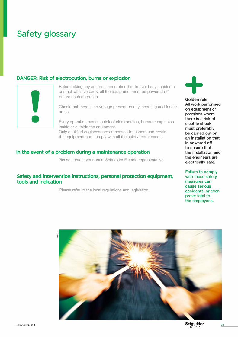
Before taking any action ... remember that to avoid any accidental contact with live parts, all the equipment must be powered off before each operation.
Check that there is no voltage present on any incoming and feeder areas.
Every operation carries a risk of electrocution, burns or explosion inside or outside the equipment. Only qualified engineers are authorised to inspect and repair the equipment and comply with all the safety requirements.
DANGER: Risk of electrocution, burns or explosion DANGER: Risk of electrocution, burns or explosion
Golden rule All work performed on equipment or premises where there is a risk of electric shock must preferably be carried out on an installation that is powered off to ensure that the installation and the engineers are electrically safe.
Failure to comply with these safety measures can cause serious accidents, or even prove fatal to the employees.
Please contact your usual Schneider Electric representative.
In the event of a problem during a maintenance operation In the event of a problem during a maintenance operation
PE
9003
7
Safety and intervention instructions, personal protection equipment, Safety and intervention instructions, personal protection equipment, tools and indication tools and indication
Please refer to the local regulations and legislation.
24
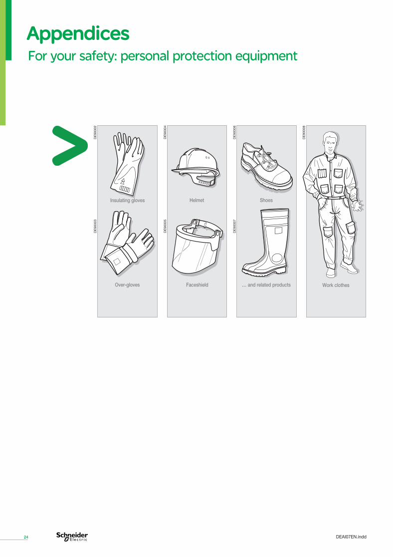
Appendices Appendices For your safety: personal protection equipment
DE
9000
2
DE
9000
4
Insulating gloves
Over-gloves
Helmet
Faceshield
Shoes
… and related products
DE
9000
6
Work clothes
DE
9000
8
DE
9000
3
DE
9000
5
DE
9000
7
DEAI07EN.indd
25
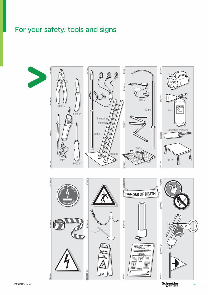
For your safety: tools and signs
DE
9000
9D
E90
010
DE
9001
1D
E90
012
1 000 V
1 000 V
1 000 VVAT
DE
9001
3
DE
9001
4D
E90
015
DE
9001
6D
E90
017
20 kV
Isolant
Insulating
material
500 V
24 kV
1 000 V
9 V
CO2
Insulating material
24 kVD
E90
018
DE
9001
9D
E90
020
DE
9002
1
DE
9002
2 E
ND
E90
023
DE
9002
4
DO NOT OPERATE
PAD
LOCKED DEVICE
DE
9002
5D
E90
026
DE
9002
7 E
N
DE
9002
8 E
ND
E90
029
DE
9003
0
DE
9003
1D
E90
032
DE
9003
3 E
ND
E90
034
DEAI07EN.indd
Schneider Electric Industries SASHead Office35 rue Joseph MonierCS 3032392506 Rueil-Malmaisonwww.schneider-electric.com
As standards, specifications and designs change from time to time, please ask for confirmation of the information given in this publication.
This document has been printed on ecological paper.
Publishing: SYNTHESE ECA, Schneider Electric.Printing:
DEAI07EN 10/2008
AR
T960
247
© S
chne
ider
Ele
ctric
Ind
ustr
ies
SA
S -
All
right
s re
serv
ed
Maintenance and Services Guide Medium-Voltage distribution - 24 kV