medium-voltage vacuum power circuitbreakerscircuit breaker. 1. below0 c, theclosingtimeswillincrease...
TRANSCRIPT
IB 6.2.7.7-4C
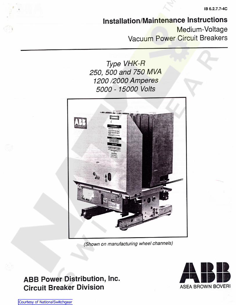
Installation/Maintenance InstructionsMedium-Voltage
Vacuum Power Circuit Breakers
Type VHK-R250, 500 and 750 MVA
1200 /2000 Amperes5000 - 15000 Volts
(Shown on manufacturing wheel channels)
JL IIII#MPIIABB Power Distribution, Inc.
Circuit Breaker Division ASEA BROWN BOVERI

ID
Page 2 MIPIPASEA BROWN BOVERI
*1
CONTENTS
PAGEINTRODUCTIONRECEIVING AND STORAGECIRCUIT BREAKER GENERAL INFORMATION
Installation InspectionVacuum Interrupter ExaminationInsulation StructureManual Operation of Electrically Operated Models
MAINTENANCE: ADJUSTMENTS AND TESTSGeneral InformationMillivolt Drop TestInsulation CleaningCircuit Breaker Operation, Contact Adjustment and Timing
Contact AdjustmentClosing and Opening Times and Speeds
Operating MechanismLatch Engagement (Bite)
Control Relay AdjustmentLUBRICATIONDIELECTRIC TESTSELECTRICAL CHARACTERISTICSELECTRICAL OPERATING SEQUENCE
DC Operating SequenceDC Schematic Diagram of Control CircuitAC Operating SequenceAC Schematic Diagram of Control Circuit
RENEWAL PARTS
333333555556667778899••••••••••••••••a
910111213
: These instructions o col pc ?;.; cvorv rassis:* centresnev :o• -?C Of 1' , .
i'le non;? *.
'Os nisr oro
r M* •- r-./>n
H • ~Jcl r y - ry r r r .
au U.4..« •# —TVs
MIMP Page 3
ASEA BROWN BOVERI
be lockwired to allow closing of the breaker for shipment. A tagwill identify the lock wire. To remove the wire, open the breakerandreachbehindthecontrolpanel fromthe righthandside. Usingwire cutters, cut and remove the tagged wire.
INTRODUCTION
These instructions for installation, operation and maintenance ofVHK-R series vacuum circuit breakers should be read carefullyand used as a guide during installation and initial operation.
The specific ratings of each modelcircuit breaker are listed on theindividual nameplates. WARNINGS WA1mm
File these instructions in a readily accessible place together withdrawings and descriptive data of the switchgear. These instruc-tions will be a guide to proper maintenance of the equipment andprolong its life and usefulness.
Prior to any disassembly or insoecticn of the circuit breaker, theclosing springs should be discharged, and the breaker shcuid beopen.
Installation InspectionRECEIVING AND STORAGE
Inspect the condition of circuit breaker vacuum interrupters andelectrical connectionsprior to installing thecircuit breaker into theswitchboard. Even though each circuit breaker is completelyadjusted and tested at the factory, shipping and handling condi-tions could cause defects.
Immediately upon receipt of the circuit breakers, examine thecartons to determine if any damage or loss was sustained duringtransit. If abuse or rough handling is evident, file adamage claimat once with the carrier and promptly notify the nearest DistrictOffice. The company isnot responsible fordamage of goods afterdelivery to the carrier, however, we will lend assistance if notifiedof claims.
Vacuum Interrupter Examination (See Fig. 1)
f >[-310*»Unpack the circuit breakers as soon as possible after receipt. Ifunpacking is delayed, difficulty may be experienced in making aclaim for damages not evident upon receipt. Usecare in unpack-ing in order to avoid damaging any of the circuit breaker parts.Check the contents of each carton against the packing list beforediscarding any packing material. If any shortage of material isdiscovered, promptly notify the nearest District Office. Informa-tion specifying the purchase order number and part numbers ofthe damaged or missing parts should accompany the claim.
: v
k grounding stick snouid be usee to ciscnarge the mid-bancon me vacuum interrupters (1) so sou ooad. before snv vccone cr. the interrupters.
The insulated vacuumenvelope (2) shouldbeexaminedcarefullyfor cracks in the area of the metal-to-insulation seals onboth endsand around the mid-band ring. Since a certain amount oftransmitted light is usually required to detect cracks, the inspec-tion should be done in a well lighted area. If the mid-band ring,when so equipped, has been bent by an accidental impact, thatarea should be specially scrutinized for seal damage. Smallexternal chips will not impair the useful life of the interrupter.
Circuit breakers shouldbe installed in their permanent location assoon as possible. If the breakers are not to be placed in servicefor some time, it is advisable to provide adequate means ofprotection. This may be done by keeping the breaker in its originalshipping carton and storing in a warm, dry and uncontaminatedatmosphere. If the circuit breaker cannot be stored properly, itmust be thoroughly checked before going into service to insure ithas not absorbed moisture, rusted or become generally contami-nated in any way.
Insulation Structure
All insulatedparts shouldbe checked for damage. Any dust or dirtshould be removedby air or wiped with aclean lintless cloth. Thelead support moldings are polyester glass and occasionally havesome resin rich cracks or crazing develop.These do not indicatedefective material and should not cause concern.CIRCUIT BREAKER GENERAL INFORMATION
Prior to initial installation of the circuit breaker into the switch-board, certain preliminary inspections should be made to insureproper operation. The inspection procedures for this are given inthis section.
NOTE: It is recommendedthat adielectric withstand test bemadeprior toputting this or any type vacuumcircuit breaker into service.Refer to Dielectric Tests, in the Maintenance, Adjustments andTests section of this bulletin, for the correct test procedure.
The circuit breaker is shipped with contacts closed, closingsprings discharged and opening springs charged. If the circuitbreaker is furnished with an undervoltage device, the device will

V tea a a a
Page 4 MWIPASEA BROWN SOVERI
A
4
SPRING STATUS INDICATOR7MOTOR POWERCON’ROL SWITCHr
MANUAL TRIPI -0C A _— ELECTRIC :1 CLOSE /'RIP
(OPTIONAL)MANUAL CLOSE
“1- r\on OPERATIONSCOUNTER
ir OPEN/CLOSEII INDICATOR
yth'MANUAL CHARGE
POR” ~U N_lW L °© ©
j4
Fig.2 - Front Circuit Breaker Panel & Accessories(See Detail 2A)
Fig. 1 - Circuit Breaker Rear - 5KV breaker shown.Lower leads for 15KV breaker are slightly higher
Detail 2A - Manual Charging Of ElectricallyOperated Circuit Breakers
Fig. 3 - Contact Pressure

II »11MIPIP
I DPage 5
ASEA BROWN BOVERI
If , however after the first inspection period there is no indicationof any problems,actualoperating experience with specific circuitswill indicate the future amount of maintenance needed for thevarious circuit breakers and the procedure can be modified asrequired.
Manual Operation of Electrically Operated Models
Electrically operated circuit breakers may be charged manuallyby a removable maintenance handle for bench tests or emer-gency operation. To manually charge the closing springs, firstposition the maintenance handle hooked section in the long sloton the pawl carrier (Refer to Figure 2). The small tab on themaintenance handle will fit the small hole of the pawl carrier.Using a pumping motion, rotate the pawl carrier until the ratchetwheel no longer rotates. At this point, the spring charged in-dicator will indicate SPRINGS CHARGED. The circuit breakercan be closed manually with the manual close lever. NOTE:Occasionally the motorcrank arm will stopinaposition that will notallow manual spring charging. When this happens, the motorcrank arm must be rotated manually by using a screwdriver torotate the crank arm sufficiently so that the springs may then bemanually charged with the maintenance handle.
Where unusual service conditions exist, as covered by ANSIStandardC37.04, it mustbe presumed thatthese conditions wereconsidered at the time of order and that the equipment suppliedwas designed for the special application and that an appropriatesupplementalmaintenanceprogramhasbeen developed. Thesemaintenance instructions only cover circuit breakers used underthe standard service conditions.
At the selected maintenance period, the following tests andadjustments should be made:
NOTE: The following tabulated tests and adjustments are all thatare normally necessary for proper maintenance and operation oftheVHK-R circuit breaker. The remaining portionsof the breaker- close coil assembly, shunt trip device, control relay, auxiliaryswitch and motor -- require no maintenance during the standardlife of the circuit breaker regardless of the operating duty.
MAINTENANCE, ADJUSTMENTS AND TESTS
General Information
The VHK-R circuit breakers are designed for minimum mainte-nance andtestedto insure that only minimum maintenance will berequired. The few adjustments that are noted are required onlywhenanoperationalcheck indicates aproblem. Of course,duringthe maintenance checks, all accessible bolts, units and screwsshould be routinely checked to insure that they are tight.
D.C. Millivolt Drop Test
During maintenance periods, the condition of the breaker currentcircuit can easily bedeterminedby performing amillivolt droptest.This test should be performed regardless of whether the circuitbreaker had interrupted low or high currents or has minimumoperations.
It is recommended that the circuit breaker be normally inspectedafter the first 2000 operations, regardless of the type of duty it isused for. These operations can be either no-load mechanical,load current switching,bulk capacitor or reactor switching opera-tions, or for motor starting applications.
Thefollowing tablelists themillivoltdropandresistance valuesforthecircuit breakerscoveredby this instructionbook,from terminalto terminal, exclusive of the primary disconnects.
Vacuum interrupters, as used on the VHK-R circuit breakers,have an inherently long contact life and will provide trouble-freeservice under varied application conditions, as long as the circuitbreaker is applied within its rating. The wear condition of theindividual vacuum interrupters will vary, depending on circuitconditions and such variables as single phase versus three-phase interruption, X/R ratio (asymmetry) and relay delay times.Of course, interruptinghigh short-circuit current will causecontacterosion to occur faster than load current interruptions. Theinterrupters for the VHK-R Circuit Breakers are tested up to2000% KSI. It is unlikely that a circuit breaker will be subjected tothis much duty during the life of the breaker and it is not expectedthat the interrupters will have to be replaced due to excessiveerosion of contacts. There is,however, a check for contact wipe(contact pressure) which is also a measure of contact erosion.This check is covered under "Circuit Breaker Operation andContacts". Whencontact wipe is less than the minimum specifiedand there is not a mechanicalproblem,then the interrupter shouldbe replaced due to contact erosion.
MV:;;iDtopilMaximum
Mte OhmsCIrculBreaker
250 1200 Ampere 8 40
* Millivolt drop with 20(fcmperes DC flowing.
Insulation Cleaning
Any dirt, dust or grease should be removed from the surfaces ofthe entire current carrying structure and vacuum interrupter*.Wiping the surface with aclean lint free cloth is normally sufficientfor this purpose.

lb b.2././-4UPage 6
ik HUMIPWASEA BROWN BOVERI
•Remember to discharge mid-band ring on interrupters soequipped.
d. The air gap is the difference between the two measure-ments.The acceptable limits are .375 -.500,with the upperlimit being approached as contact wipe approaches theminimum.Circuit Breaker Operation, Contact Adjustment and Timing
Contact Adjustment 5. Contact Sequence Check (See Fig. 3). All three poles shouldtouch within 2 millisecond at normal closing speeds. An oscillo-scope, oscillograph or other timing method may be used toestablish the 2 millisecond timing.
1. To check breaker operation, the breaker should be withdrawnfrom the switchboard, and the racking screw turned two to threeturns clockwise until the racking unlocking lever snaps into thefirst position corresponding to the disconnect position. Before checking contact sequence, check that the contact wipe
and air gaps are correct. It is not expected that the contactsequence should exceedthe 2 millisecond limit;therefore,beforeattempting to readjust, check that the test equipment and proce-dure are correct. Also consider, especially when testing withelectronicequipment,that.002secondsvacuurn interruptercontactbounce is permissible during normal closing and this bounce caninfluence the contact touch measurements.
2. Fully Closed Breaker Test (See Fig. 2). Charge the closingsprings and turn the motor switch (1) off. Close the breaker.Engage manualcharge handle withcharging lever (3). Duringtheinitial portion of the downward stroke of the handle check to seewhich direction the closing spring guides move. If the springguides start to move out then the breaker did fully close. If thespring guides begin to move in and with additional pumpingmoves in until the mechanism can be heard to "snap in", then thebreaker did not fully close originally. Excess contact pressure orfriction can cause this condition and if it cannot be relieved thenthe factory should be consulted.
If it is determined that the contact sequence is not within the 2milliseconds, then adjustment is required. Usually, readjustmentof one pole should be sufficient so that all three poles touch within2 milliseconds. The air gap of the pole to be changed should bedecreased if the contacts of that pole are touching after the othertwo poles, or increased if the contacts are touching before theother two poles. The air gap is decreased by turning pushrod (2)clockwise, viewing from the top of the breaker, and increased byturning conterclockwise.
3. Contact Wipe (contact pressure) Check (See Fig. 3). Thecontact air gap and contact wipe is set at the factory by setting thevertical position of the interrupter (1) and the vertical position ofthe pushrod (2). These parts should not be repositioned in thefield unless a pushrod change is required to correct contactsequence as described elsewhere. Contact wipe is set at thefactory at .093 minimum. Contact erosion and wear inmechanicalparts will cause a reduction in contact wipe over the life of thebreaker and a check should be made to insure that the wipe is notless than.020". Themeasurement ismade as follows forthe threepoles:
1/4 turn of the pushrod (2) will change the air gapby approx..019.After rotating the pushrod, carefully reposition the movingcontactand pushrod vertically to align the pin holes. Replace the pin andretainer. During the readjustment procedure note that the contactwipe and air gap dimensions, specified previously, must bemaintained. No more than 1/2 turn total of the pushrod shouldberequired when readjusting for contact sequence.
a. Close the breaker and measure between the spring baseand nut (point A), using gage pin. After completing the contact sequence procedure, recheck the
contact wipe and air gaps.b. The measurement with the breaker open should be at least
.093 for a new breaker. Return the racking screw to its original position by turning itcounterclockwise approx, two to three turns until it stops.
c. When contact wipe is less than the .020 and it has beendetermined that the breaker closes fully and there is not amechanical problem, then the interrupter should be re-placed due to contact erosion.
Closing and Opening Times and Speeds
After the operation intervals noted previously, the closing andopening times are recommended to be checked by use of a cyclecounter, travel recorder*, oscillograph, etc. to monitor the timefrom energizing to contacts touch or part.
4. Contact Air Gap Check (See Fig. 3). The contact air gap is setat the factory at the nominal dimension of .40. This value willnormally increase as the contacts erode. A check of the contactair gap checks that the breaker does open fully and that the gapis sufficient to withstand the applied voltage. The measurementis made as follows for the three poles. * A potentiometer with mounting support, used in conjunction with
an oscilloscope or oscillograph, and instructions are available onspecialorderfor specifically checkingopening andclosing speeds.a. Open the breaker and discharge the closing springs.
b. Measure and record the dimension between the top sur-face of the flex connector clamp and the lead mountingbracket.
c. Close the breaker, measure and record the same dimen-sion.
aiiitMIPIP
ID 0.Z././-4UPage 7
ASEA BROWN BOVERI
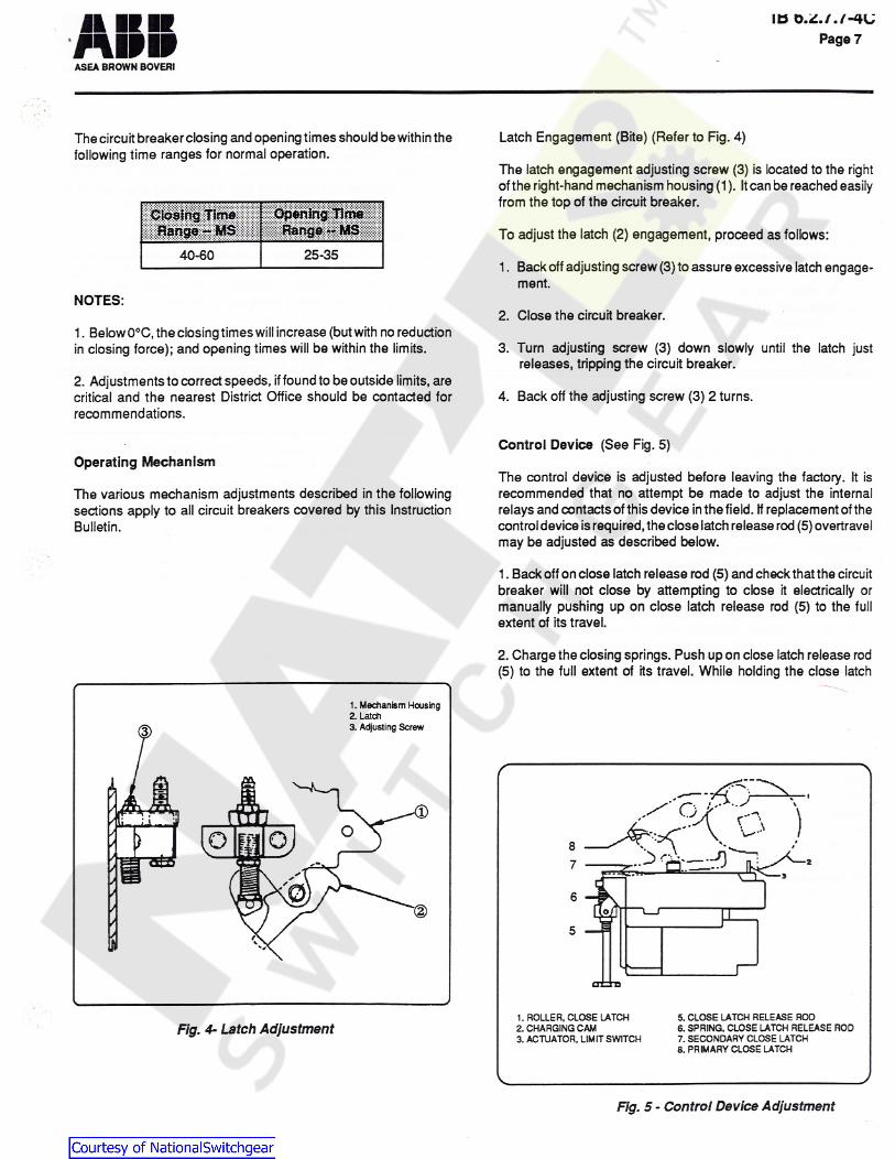
Latch Engagement (Bite) (Refer to Fig. 4)Thecircuit breaker closing and opening times should be within thefollowing time ranges for normal operation.
The latch engagement adjusting screw (3) is located to the rightof the right-hand mechanism housing (1). It canbe reached easilyfrom the top of the circuit breaker.
Opening TimepoeihgillmfiTo adjust the latch (2) engagement, proceed as follows:
25-3540-601. Backoff adjustingscrew (3) to assure excessive latch engage-
ment.NOTES:
2. Close the circuit breaker.1. Below0°C,theclosing times will increase (but with no reductionin closing force); and opening times will be within the limits. 3. Turn adjusting screw (3) down slowly until the latch just
releases, tripping the circuit breaker.2. Adjustments to correct speeds, if foundto beoutside limits,arecritical and the nearest District Office should be contacted forrecommendations.
4. Back off the adjusting screw (3) 2 turns.
Control Device (See Fig. 5)Operating Mechanism
The control device is adjusted before leaving the factory. It isrecommended that no attempt be made to adjust the internalrelays and contacts of this device inthe field. If replacement of thecontroldevice isrequired,thecloselatchrelease rod (5) overtravelmay be adjusted as described below.
The various mechanism adjustments described in the followingsections apply to all circuit breakers covered by this InstructionBulletin.
1.Back off onclose latch release rod (5) and check that the circuitbreaker will not close by attempting to close it electrically ormanually pushing up on close latch release rod (5) to the fullextent of its travel.2.Charge the closing springs. Push up on close latch release rod(5) to the full extent of its travel. While holding the close latch
1. Mechanism Housing2. Latch3. Adjusting Screw£
2
A// 5/
IN
UZ-ID
1.ROLLER.CLOSE LATCH2.CHARGING CAM3. ACTUATOR. LIMIT SWITCH
5.CLOSE LATCH RELEASE ROO6.SPRING. CLOSE LATCH RELEASE ROD7.SECONDARY CLOSE LATCH8.PRIMARY CLOSE LATCH
Fig. 4- Latch Adjustment
Fig. 5 - Control Device Adjustment
iiminvplb b.2././-4UPage 8
ASEA BROWN BOVERI
1. The internal shield of a vacuum interrupter can acquire anelectrical charge which is usually retained even after the voltageis removed.Oncertain types of interrupters,this shield is attachedto the exposed mid-band ring and a grounding stick should beused to discharge the ring before working on the device.
LUBRICATION
The VHK-R circuit breakers are lubricated during factory assem-bly as follows:
1. The primary disconnect contacts have been lubricated withNO-OX-ID special grade-A grease manufactured by Sanchem,Inc. (ABB No. 713222A, 1 Pt. can).
2. Dielectric test voltages higher than rated voltage, appliedacross open contacts, may cause a vacuum interrupter to emitsome X-radiation which could be a health hazard on prolongedexposure at close range. Accordingly, even though the emissionis low and on for such a short period of time, it is consideredappropriate to exercise caution.
2. All other mechanism parts, bearings, pins, etc., have beenlubricated with Anderol 757 manufactured by Nuodex, Inc. (for-merly Tenneco Chemical, Inc). (ABB No. 712994A, 4 oz. tube).
Therefore,do not run any primary circuit dielectric withstand testson isolated interrupters with open contacts, above rated voltageunless tost personnel are adequately shielded or they are no lessthan six feet from the test unit.
If the grease should become contaminated or unduly oxidized(hardened and darkened) or if parts are replaced, any relubrica-tion should be done with the lubricants noted.
NOTES:It is noted that NO hazardous X-radiation isproduced with closedcontacts at any test voltage or with open contacts at rated voltageand there should be no cause for concern. Further, if the breakeris tested in its switchgear compartment, the enclosure steelprovides sufficient shielding to protect personnel from X-radiationat the test voltages recommended below at the normal distancesmaintained for electrical safety.
1. It is recommended that the primary disconnects be maintainedby renewing the grease. The mechanism should be periodicallyinspected for lubrication contamination; frequency of inspectionis dependant on operating environment.2. Do not use light oil to lubricate any mechanism parts. Inemergency situations, Anderol 732 may be used as a temporarylubricant. In these cases, allow time for the solvents to evaporateprior to any mechanical operations. It is mandatory that thebreaker undergo thorough lubrication with Anderol757atthe nextmaintenance interval. Use of solvents to free contaminatedlubricant is strictly forbidden without immediate relubricationusing Anderol 757. Note that bearing surfaces must be repackedand this will require disassembly of the mechanism. Do notoperate circuit breaker without completing this procedure.
The following test values should be used for dielectric testing thenew breaker and are to be applied for a one-minute period.
Deicrlptfoi 60HzPrimary Circuit 19.0kV
5 KV3. The charging motor is sealed and no lubrication is required. * Secondary Circuit (Control) 1100V
36.0kVPrimary Circuit15 KVDIELECTRIC TESTS 1100V* Secondary Circuit (Control)
It is recommended that dielectric withstand tests be made priortouse and then at routine maintenance periods to verify the integrityof vacuum interrupters. If, during the dielectric withstand test, therequired test voltage cannot be sustained across the open con-tacts of the vacuum interrupter, the interrupter is faulty and mustbe replaced. Always insure that the contact air gap is correctbefore conducting primary circuit dielectric tests.
Once in service, the primary circuit should be tested at 75%of thisrating
*lf it is desired to make a dielectric test on the secondary controlwiring, turn the spring charging motor disconnect switch (1, Fig.3) to the "OFF" position. Apply test voltage (1100V-AC) for oneminute to each of the secondary disconnect contacts at the rearof the circuit breaker.’* 1 > 1 * vhTJ f ?»,
If it is desired to make a dielectric test on the spring chargingmotor, turn the motor disconnect switch (1, Fig. 3) to the "ON"position. Apply test voltage (540V-AC) for oneminuteto the motorcircuit.
<2./-- : Ol -a.\irvare are :wo
.. ^ v f r - * t !s u w i i t f c r y* L I S A:r- *| • _.w i * i.i I. . J I. *»•

ID U.*..# ./ -HUPago 9MIPIP
ASEA BROWN BOVERI
3. When the springs discharge, limit switch contact "LSb" closesand switch contact "LSa" opens.ELECTRICAL CHARACTERISTICS
OF CONTROL DEVICES4. When limit switch "LSb" in the motor circuit closes, the springcharging motor is energized, which in turn recharges the closingsprings.
For operating voltage ranges for various nominal control volt-ages, refer to Table 1.For average current values at various nominal control voltages,refer to Table2. Thecurrent valuesgiven in this table areaverage,steady state values and momentary inrush currents for all charg-ing motors and ACcoils are approximately six to eight times thesevalues.
5.Whenthecircuit breakercloses,all auxiliary switch"b"contactsopen and all auxiliary switch "a" contacts close.
6. When the limit switch contact "LSb" closes, the lockout relaycoil (Y) is energized and opens lockout relay contact "Yb", whichdeenergizes the latch release coil (X). Lockout relay contact "Ya"closes, which seals-in the lockout relay coil (Y) as long as the"close" contact is maintained. The purpose of the lockout relaycoil (Y) is to prevent pumping of the closing mechanism whenclosing against a faulted circuit.
ELECTRICAL OPERATING SEQUENCE
Please refer to the specific schematic diagrams and other opera-tional information furnished with your order.
7. After the breaker has closed and when the "close" switch isreleased by theoperator,the lockout relay coil (Y) is deenergized.This allows the normally-closed lockout relay contact "Yb" toclose, and the normally-open lockout relay contact "Ya" to open.
Figure 10 and 11 are provided as typical schematics for generalinformation on electrical operation.
DC CLOSING OPERATING SEQUENCE 8. Thecircuit breakercanbetrippedby operationof the tripcontrolswitch which energizes the circuit breaker trip coil (TC) throughthe auxiliary switch "a" contact.With the circuit breaker open, the closing springs uncharged, and
the control power source energized,and motor disconnect switchclosed, operation occurs as follows: 9. The undervoltage device, if furnished, provides a direct acting
lock-open and undervoltage tripping feature. This device must beenergized to initially close the breaker, and also to maintain thebreaker in a closed position.
1. Immediately upon the availability of control power, the springcharging motor (motor) is energized, which in turn charges theclosing springs. When the closing springs are charged, limitswitch contact "LSb" is opened, and limit switch contact "LSa" isclosed.
10. The latch check switch, if furnished, insures that the trippingmechanism must be reset prior to energizing the closing latchrelease coil (X).
2. Operation of the Close Control switch energizes the latch re-lease coil (X) through the circuit breaker auxiliary switch "b"contact, the normally closed lockout relay contact "Yb", and thelimit switch contact "LSa". The latch release coil (X) releases theclosing latch. The springs then discharge to close the circuitbreaker.
11. The stopping device switch, if applicable, prevents electricalreclosing of thecircuit breaker after amanualtripuntil the stoppingdevice has been manually reset.
Table 1 - Operating Voltage Range
UndervoitageSpringChargingSi:Motor I
Nominal Close Trip|ControlVoltagi ||Pick-upl;
MaximumCoil Cd3f Drop-out
48 Vdc 28 - 56 15 - 294138 - 56 38 - 56125 Vdc 70 - 140100 - 140 38 - 75100 - 140 105
212 75 - 150140 - 280250 V dc 200 - 280 200 - 280104 - 127120 Vac 102104 - 127 36 - 72104 - 127
74 - 144240 V ac 204208 - 254 208 - 254208 - 254

a a
Page 10 npvASEA BROWN BOVERI
Table 2 •Average Current Values
NominalControlVoltage
SpringCharging
MotorH.E.C.Fuse
Close mim |Urater|Voltage
LockoutColli CoilColl
48 Vdc 25.0 0.310.7 303.14 0.15
125 Vdc 10.0 305.0 1.3 0.06 0.2
250 V dc 305.0 2.2 0.65 0.03 0.1
120 Vac 10.0 4.5 306.5 0.40 0.5
240 V ac 2.35.0 0.20 0.21.15 30
501 502 503LEGEND
- Auxiliary Switch Contact Closed WhenBreaker Is Closed.
b Auxiliary Switch Contact Open WhenBreaker Is Closed.Latch Check Switch Contact Closed WhenBreaker Operating Mechanism Is Reset. (Option)
LSa Limit Switch Contact Open When Springs AreDischarged. Closed When Springs Are Charged.
LSb Limit Switch Contact Closed When Springs AreDischarged. Open When Springs Are Charged.Shunt Trip Coil.Control Relay Release Coil.Control Relay Lockout Coil.Normally Open Control Relay Contact.Normally Closed Control Relay Contact.
-Terminal Block Point.Motor Lead.Coil Lead End.
C1,C2- Terminal Jumper (Control Device).<- Female Secondary Disconnect Contact.
a —
C3 J2 C I I4IO LCb -YLS LSbuJ* a
I5I3 C22
'i38 IS b TC -azlb X -9Y
232 52 YaYbI6
'IO ML -b2 m17 CEnlo 2 o mmlo ui
I? <s> 00o15 (MOTOR18 n on
PI mmr rO *C4l</> m5
504 505 506
Figure 8 - Typical DC Schematic DiagramOf Control Circuit

II IK IKMIPIP
I D U. ./ ./ V/
Page 11
ASEA BROWN BOVERI
AC CLOSING OPERATING SEQUENCE 10. The latchcheck switch, if furnished,insures that the operatingmechanism must be reset prior to energizing the closing latchrelease coil (X).With the circuit breaker open,the closing springs uncharged, and
the controlpower source energized across disconnects "5"& "02"and "01" & "6", motor disconnect switch closed, operation occursas follows:
11. The remote mounted capacitor trip feature, if furnished,provides an electrical energy storage network, whereby should aloss of control power occur at the instant of a tripping signal,sufficient energy will be furnished to insure an electrical trippingoperation.
1. Immediately upon the availability of controlpower at secondarydisconnects "5" and "02", the spring charging motor (motor) isenergized, which in turn charges the closing springs. When theclosing springs are charged, limit switch contact "LSa" is closed.Also,upon availability of control power at secondary disconnects"01" and "6" and after the closing springs have been charged, thelockout relay coil (Y) will be energized through the circuit breakerauxiliary switch "b" contact and the parallel resistors Ri and R2.The lockout relay will pick up and close contact "Ya".
12. The stopping device switch, if applicable, prevents electricaireclosing of the Circuit Breaker after a manual trip until thestopping device switch has been manually reset.
2. Connecting secondary disconnects "03 or "7" to control viaoperation of the close control switch energizes the latch releasecoil (X) through the circuit breaker auxiliary switch "b" contact, thenormally open lockout relay contact "Ya", and the limit switchcontact "LSa". The latch release coil (X) releases the closinglatch. The springs then discharge to close the circuit breaker.3. When the springs discharge, limit switch contact "LSb" closesand limit switch contact "LSa" opens.
4. When limit switch contact "LSb" in the motor circuit closes, thespring charging motor is energized, which in turn recharges theclosing springs.
5. When thecircuit breakercloses,all auxiliary switch"b"contactsopen and all auxiliary switch "a" contacts close.6. When the limit switch contact "LSa" opens, both the latchrelease coil (X) and the lockout relay coil (Y) are deenergized.Contact "Ya"opens the latch release coil (X) circuit. Contact "Yb"closes connecting resistors "R1" and "R2" directly to controlpoweras long as the close control switch remains closed. The circuitbreaker is prevented from any automatic reclosing in the event"LSa" and auxiliary switch "b"close because "Ya" remains open.The "Yb" contact shorts out the lockout relay coil (Y) throughresistors "R1" and "R2". The purpose of the lockout relay is toprevent pumping of the circuit breaker's mechanism whenclosingagainst a faulted circuit.7. After the breaker has closed and when the closing controlswitch is released by the operator, the lockout relay coil (Y)remains deenergized due to the auxiliary switch "b"contact in theclosing circuit being open.
8. The circuit breaker can be tripped by operation of the "RemoteTrip" switch, which energizes the circuit breaker trip coil (TC)through the auxiliary switch "a" contact.9. The undervoltage device, if furnished, provides a direct actinglock-open and undervoltage tripping feature. This device mustbeenergized to initially close the breaker, and also to maintain thebreaker in a closed position.

ID O
Page 12nnnMlfWASEA BROWN BOVERI
501 502 507 503
4 6CE4 34
YCE3
16 C1 14 528 LS Yb Ya5b 41 15943 CE1 CE52
R R ® ©0 21fk
Q CE 2 CE6o 44O ML1 42X 25a
'8 MOTOR 35OzIm 101ML2n LSa
11cnl*
4b
3
505 506Figure 9 - AC Schematic Diagram Of Control Circuit
504
LEGENDControl Relay Release Coil.Control Relay Lockout Coil.Normally Open Control Relay Contact.Normally Closed Control Relay Contact.Terminal Block Point.
ML Motor Lead.Coil Lead End.
C1, C2- Terminal Jumper (Control Device).I- Female Secondary Disconnect Contact.
R1, R2- Resistors
XAuxiliary Switch Contact Closed WhenBreaker Is Closed.Auxiliary Switch Contact Open WhenBreaker Is Closed.
l_Ct> Latch Check Switch Contact Closed WhenBreaker Operating Mechanism Is Reset. (Option)
LSa Limit Switch Contact Open When Springs AreDischarged. Closed When Springs Are Charged.
LSb Limit Switch Contact Closed When Springs AreDischarged. Open When Springs Are Charged.Shunt Trip Coil.
aYYabYb
CE
TC
I k#
MIPIP Page 13
ASEA BROWN BOVERI
RENEWAL PARTS
We recommend only those renewalparts that will be required toinsure proper and timely maintenance for normal operation ofthe VHK-Rcircuitbreakersbestocked. Copies of the applicableRenewal Parts Bulletin for specific circuit breakers will befurnished on request to the nearest District Office.
The minimum quantity of assemblies and items recommendedin these bulletins are predicated on infrequent replacement ofparts based on accumulated tests and operating experience.Total assemblies are recommended for fast replacement,whenit is necessary to return the breaker to service as quickly aspossible. Replaced assemblies can be returned to the factoryfor nominal reconditioning. The bulletins contain specific partordering instructions. If desired, specific instructions regardingreplacement of those part assemblies are also available.


JiltI!MVIP
ID 0.Z././-4UPage 13
ASEA BROWN BOVERI
RENEWAL PARTS
We recommend only those renewal parts that will be required toinsure proper and timely maintenance for normal operation ofthe VHK-Rcircuit breakersbe stocked. Copies of the applicableRenewal Parts Bulletin for specific circuit breakers will befurnished on request to the nearest District Office.
The minimum quantity of assemblies and items recommendedin these bulletins are predicated on infrequent replacement ofparts based on accumulated tests and operating experience.Total assemblies are recommended for fast replacement,whenit is necessary to return the breaker to service as quickly aspossible. Replaced assemblies can be returned to the factoryfor nominal reconditioning. The bulletins contain specific partordering instructions. If desired, specific instructions regardingreplacement of those part assemblies are also available.

A
A 11»AIPIIASEA BROWN BOVERI
ASEA BROWN BOVERI, INC.ABB Power Distribution Inc.Circuit Breaker DivisionP.O. Box 100524Florence, South Carolina 29501
Printed in U.S.A. 50C
Phone: (803) 665-4144Telecopier: (803) 664-0520
i