meeting the odot survey & mapping...
TRANSCRIPT

10/2/2015
1
Meeting the ODOT Survey & Mapping
SpecificationsA Simple Solution
Presented by Ray Foos, P.S, ODOT CADD & Mapping Services
& Jon Keller, P.S., ODOT District 3
Field Work
Phases of an ODOT Survey Project
Research
Processing Deliverables

10/2/2015
2
But First Things First…
Equipment Calibration
Property Owner Notification Letters
(Give the dog a head’s up.)
OUPS
Equipment Calibration and Maintenance
603 Equipment Calibration and Maintenance
Ensure all surveying equipment is calibrated and adjusted in accordance with the manufacturer’s recommendations. Documentation of all equipment adjustments and calibrations shall be kept and made available to ODOT upon request. Refer to the following criteria as a minimum for equipment maintenance:

10/2/2015
3
603.1 Levels
Ensure professional calibration and servicing is performed per the manufacturer’s specifications.
In addition, perform maintenance and care according to the following schedule:
Every 3 Months:
Clean and inspect optics, electrical contacts, instrument body, and instrument case
Check and adjust level vials
Peg test the level and adjust as needed
603.2 Total Stations Ensure professional calibration and servicing is performed per the
manufacturer’s specifications.
In addition, perform maintenance and care according to the following schedule:
Every 3 Months:
Clean and inspect optics, electrical contacts, instrument body, and instrument case
Check and adjust level vials
Check and adjust vertical plummet
Every 6 Months:
Check horizontal and vertical circle collimation and adjust as needed
Check calibration of E.D.M. on a baseline and adjust as needed
10/2/2015
4
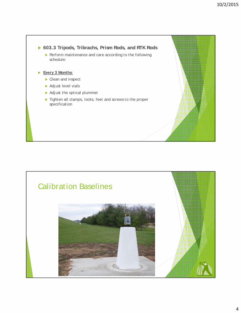
603.3 Tripods, Tribrachs, Prism Rods, and RTK Rods
Perform maintenance and care according to the following schedule:
Every 3 Months:
Clean and inspect
Adjust level vials
Adjust the optical plummet
Tighten all clamps, locks, feet and screws to the proper specification
Calibration Baselines
10/2/2015
5
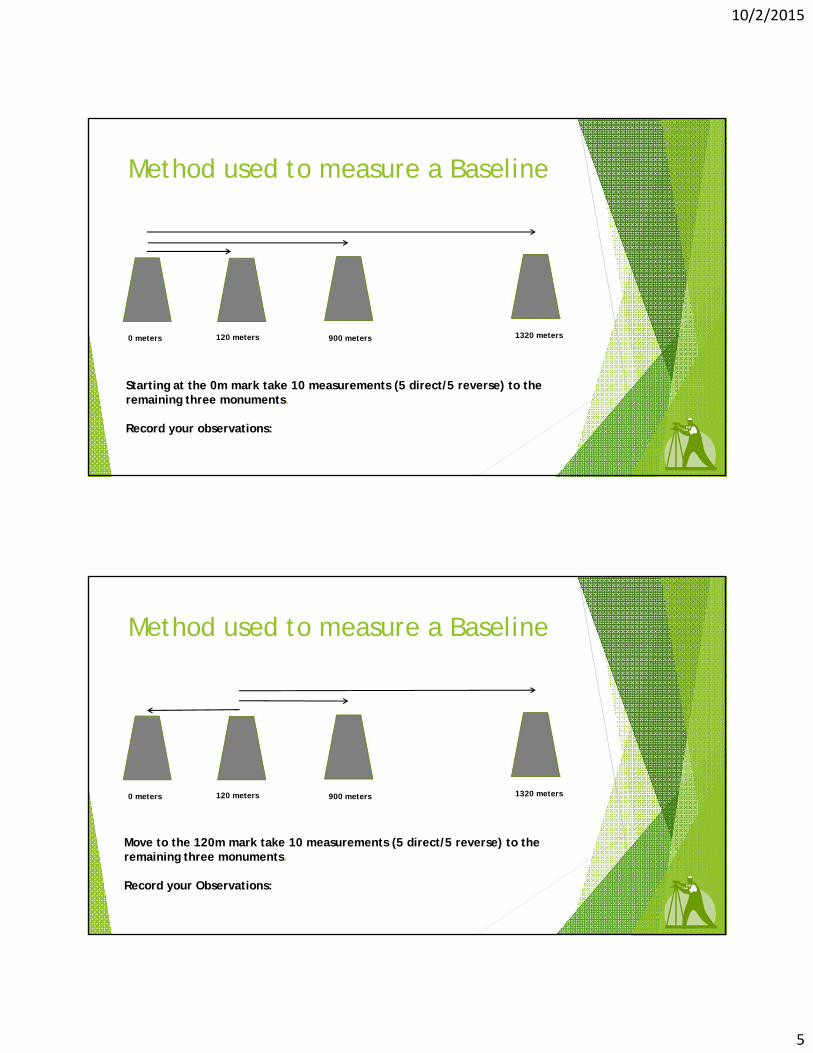
Method used to measure a Baseline
0 meters 120 meters 900 meters 1320 meters
Starting at the 0m mark take 10 measurements (5 direct/5 reverse) to the remaining three monuments.
Record your observations:
Method used to measure a Baseline
0 meters 120 meters 900 meters 1320 meters
Move to the 120m mark take 10 measurements (5 direct/5 reverse) to the remaining three monuments.
Record your Observations:
10/2/2015
6
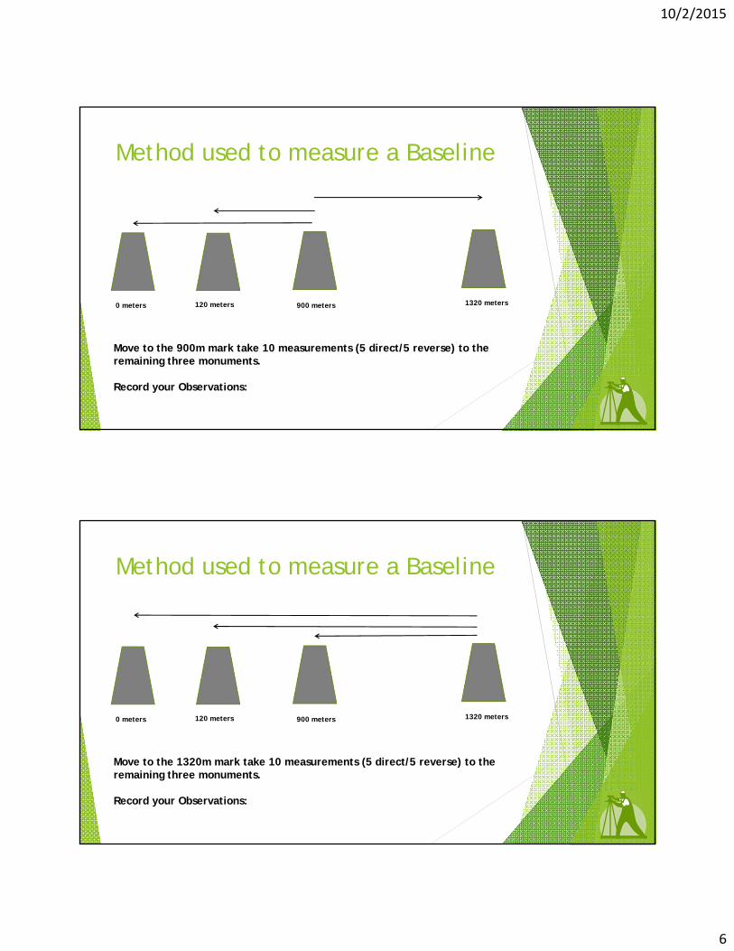
Method used to measure a Baseline
0 meters 120 meters 900 meters 1320 meters
Move to the 900m mark take 10 measurements (5 direct/5 reverse) to the remaining three monuments.
Record your Observations:
Method used to measure a Baseline
0 meters 120 meters 900 meters 1320 meters
Move to the 1320m mark take 10 measurements (5 direct/5 reverse) to the remaining three monuments.
Record your Observations:

10/2/2015
7
Here’s what we do with the DATA
Property Owner Letters
501.1PropertyOwnerNotificationofEntry
Survey crews performing work for the Department are granted access to private land per O.R.C.163.03 & O.R.C. 5517.01. Property owner notification is required at least 48 hours in advance. A standard property owner notification form is included in Appendix G. Both ODOT and consultant surveyors are responsible for any damage to the property of others incurred during the process of their work. Should any damages occur; the survey crew chief will document the damage and deliver a report to the District.

10/2/2015
8
Research
County Engineer, Auditor & Recorder Offices Most state highways were formerly county roads
Research
State Route numbers are not forever Current State Route numbering system was preceded by the Inter-County Highways

10/2/2015
9
Research
Plans Field Books ROW Monument Reports
Available from ODOT:
Contact District 3 Survey for Records
Scott Hawkins, P.S. (Survey) [email protected]
(419) 207-2823
Jon Keller, P.S. (Survey) [email protected]
(419) 207-7030
James Kenyon, P.S. (Real Estate) [email protected]
(419) 207-7112
10/2/2015
10
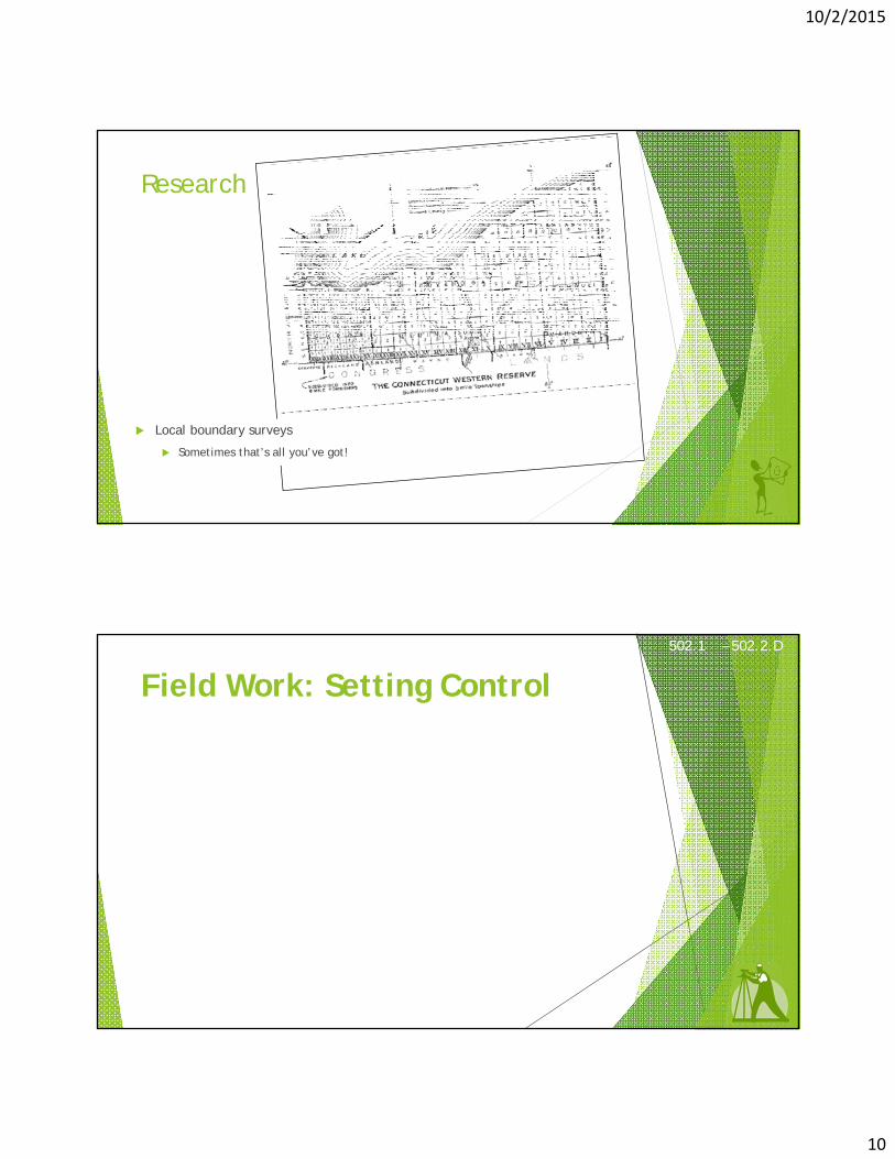
Research
Local boundary surveys
Sometimes that’s all you’ve got!
Field Work: Setting Control
This satisfies sections
502.1 – 502.2.D of the Surveying & Mapping Specifications for Minor Projects
502.1 – 502.2.D

10/2/2015
11
BUT FIRST!!!

10/2/2015
12
YOU DIDN’T THINK YOU WERE GOING TO GET THROUGH TODAY WITHOUT TALKING ABOUT STATE PLANE COORDINATES?
DID YOU?!?
GOOD COORDINATION BEGINS WITH GOOD COORDINATES

10/2/2015
13
State Plane Coordinates 101:
The Shape of the EarthEarth is not flat
Earth is not a sphere
An ellipsoid is a simplified model of Earth’s Shape
A datum is a set of reference locations, including elevations, describing more precisely the surface of the Earth
THE ELLIPSOIDMATHEMATICAL MODEL OF THE EARTH
a = Semi major axisb = Semi minor axisf = a-b = Flattening
a
b
a
N
S

10/2/2015
14
UNITED STATESELLIPSOID DEFINITIONS
CLARKE 1866a = 6,378,206.4 m 1/f = 294.97869821
GEODETIC REFERENCE SYSTEM 1980 - (GRS 80)a = 6,378,137 m 1/f = 298.257222101
WORLD GEODETIC SYSTEM 1984 - (WGS 84)a = 6,378,137 m 1/f = 298.257223563
BESSEL 1841a = 6,377,397.155 m 1/f = 299.1528128
State Plane Coordinates 101:
10/2/2015
15
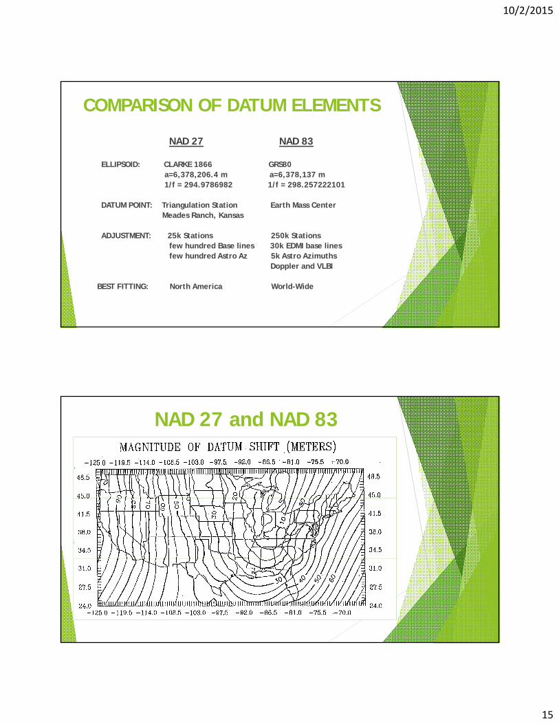
COMPARISON OF DATUM ELEMENTS
NAD 27 NAD 83
ELLIPSOID: CLARKE 1866 GRS80a=6,378,206.4 m a=6,378,137 m1/f = 294.9786982 1/f = 298.257222101
DATUM POINT: Triangulation Station Earth Mass CenterMeades Ranch, Kansas
ADJUSTMENT: 25k Stations 250k Stationsfew hundred Base lines 30k EDMI base linesfew hundred Astro Az 5k Astro Azimuths
Doppler and VLBI
BEST FITTING: North America World-Wide
NAD 27 and NAD 83
10/2/2015
16
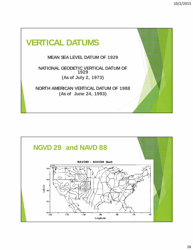
VERTICAL DATUMS
MEAN SEA LEVEL DATUM OF 1929
NATIONAL GEODETIC VERTICAL DATUM OF 1929
(As of July 2, 1973)
NORTH AMERICAN VERTICAL DATUM OF 1988(As of June 24, 1993)
NGVD 29 and NAVD 88
32
10/2/2015
17
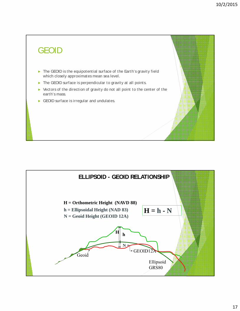
GEOID
► The GEOID is the equipotential surface of the Earth’s gravity field which closely approximates mean sea level.
► The GEOID surface is perpendicular to gravity at all points.
► Vectors of the direction of gravity do not all point to the center of the earth’s mass.
► GEOID surface is irregular and undulates.
ELLIPSOID - GEOID RELATIONSHIP
H h
EllipsoidGRS80
H = Orthometric Height (NAVD 88)
N
Geoid
H = h - Nh = Ellipsoidal Height (NAD 83)N = Geoid Height (GEOID 12A)
GEOID12A
10/2/2015
18
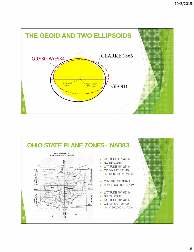
THE GEOID AND TWO ELLIPSOIDSTHE GEOID AND TWO ELLIPSOIDS
GRS80-WGS84CLARKE 1866
GEOIDEarth MassCenter
Approximately236 meters
OHIO STATE PLANE ZONES - NAD83
► LATITUDE 41° 42’ N► NORTH ZONE► LATITUDE 40° 26’ N► ORIGIN LAT 39° 40
X=600,000 m, Y=0 m
► CENTRAL MERIDIAN► LONGITUDE 82° 30’ W
► LATITUDE 40° 02’ N► SOUTH ZONE► LATITUDE 38° 44’ N► ORIGIN LAT 38° 00’
X=600,000 m, Y=0 m

10/2/2015
19
Gratuitous Disclaimer Time!!!
Warning!!! The following content is the methodology and reasoning used by the Surveyors at ODOT District 3 for scaling grid coordinates to ground. It is not to be construed as standard practice for all of ODOT. You must contact each individual ODOT District Survey Operations Manager to determine the method used and final deliverable for their respective Districts.
Grid to Ground and State Plane Coordinates Why do we worry about this?
10/2/2015
20
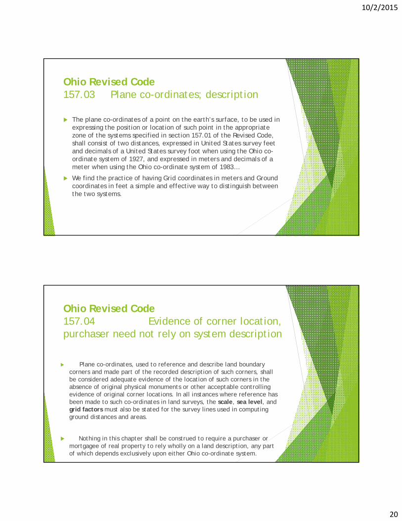
Ohio Revised Code157.03 Plane co-ordinates; description
The plane co-ordinates of a point on the earth’s surface, to be used in expressing the position or location of such point in the appropriate zone of the systems specified in section 157.01 of the Revised Code, shall consist of two distances, expressed in United States survey feet and decimals of a United States survey foot when using the Ohio co-ordinate system of 1927, and expressed in meters and decimals of a meter when using the Ohio co-ordinate system of 1983…
We find the practice of having Grid coordinates in meters and Ground coordinates in feet a simple and effective way to distinguish between the two systems.
Ohio Revised Code157.04 Evidence of corner location, purchaser need not rely on system description
Plane co-ordinates, used to reference and describe land boundary corners and made part of the recorded description of such corners, shall be considered adequate evidence of the location of such corners in the absence of original physical monuments or other acceptable controlling evidence of original corner locations. In all instances where reference has been made to such co-ordinates in land surveys, the scale, sea level, and grid factors must also be stated for the survey lines used in computing ground distances and areas.
Nothing in this chapter shall be construed to require a purchaser or mortgagee of real property to rely wholly on a land description, any part of which depends exclusively upon either Ohio co-ordinate system.
10/2/2015
21
Ohio Revised Code157.09 Distances, bearings, and areas computed indirectly from co-ordinates
Distances, bearings, and areas computed indirectly from co-ordinates shall be considered acceptable measurement evidence for land and other surveys if such co-ordinates have been determined in accordance with sections 157.04, 157.07, and 157.08 of the Revised Code
The Error Piggy Bank

10/2/2015
22
Why introduce unnecessary error?
What errors are acceptable?
You be the Judge.
Don’t feed the Error Pig!
10/2/2015
23
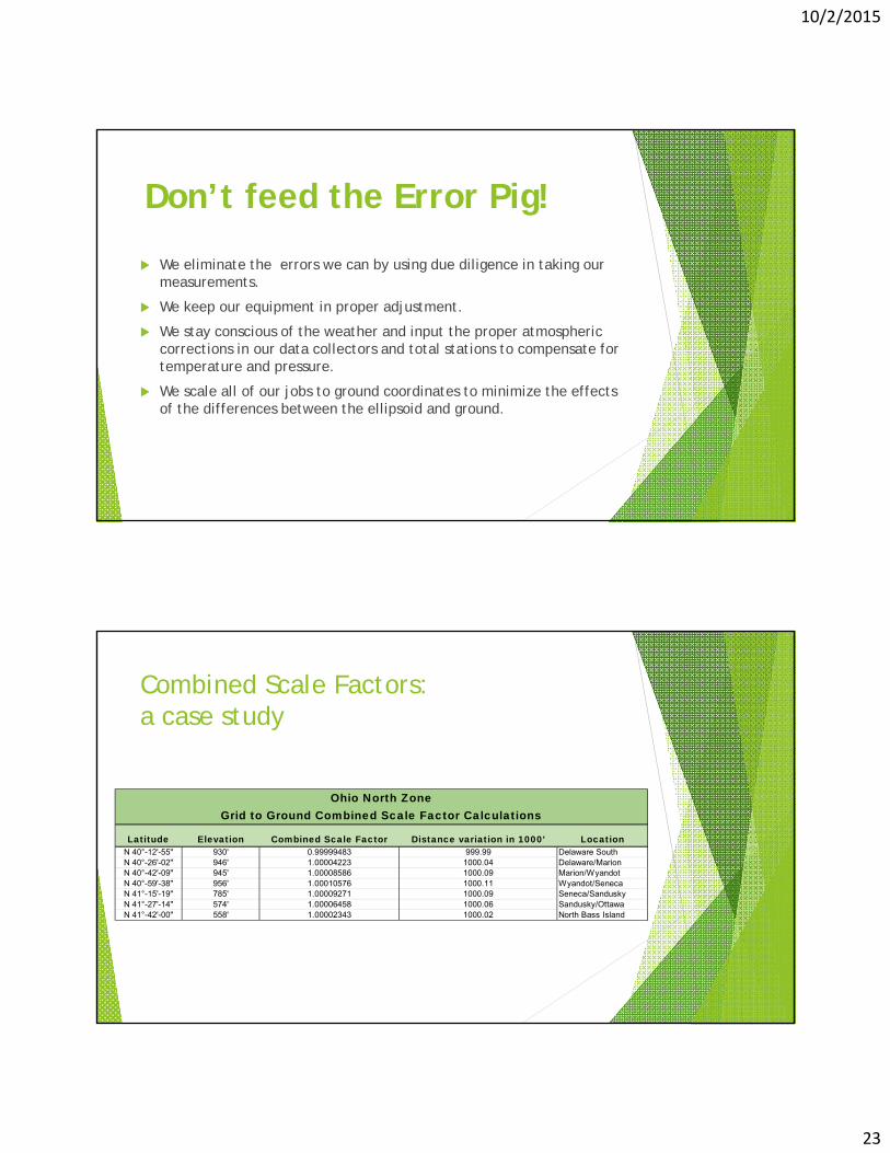
We eliminate the errors we can by using due diligence in taking our measurements.
We keep our equipment in proper adjustment.
We stay conscious of the weather and input the proper atmospheric corrections in our data collectors and total stations to compensate for temperature and pressure.
We scale all of our jobs to ground coordinates to minimize the effects of the differences between the ellipsoid and ground.
Don’t feed the Error Pig!
Combined Scale Factors:a case study
Latitude Elevation Combined Scale Factor Distance variation in 1000' LocationN 40°-12'-55" 930' 0.99999483 999.99 Delaware SouthN 40°-26'-02" 946' 1.00004223 1000.04 Delaware/MarionN 40°-42'-09" 945' 1.00008586 1000.09 Marion/WyandotN 40°-59'-38" 956' 1.00010576 1000.11 Wyandot/SenecaN 41°-15'-19" 785' 1.00009271 1000.09 Seneca/SanduskyN 41°-27'-14" 574' 1.00006458 1000.06 Sandusky/OttawaN 41°-42'-00" 558' 1.00002343 1000.02 North Bass Island
Ohio North ZoneGrid to Ground Combined Scale Factor Calculations

10/2/2015
24
We got through the “WHY” now let’s focus on the “HOW”
Field Work: Setting ControlKnow your Path
10/2/2015
25
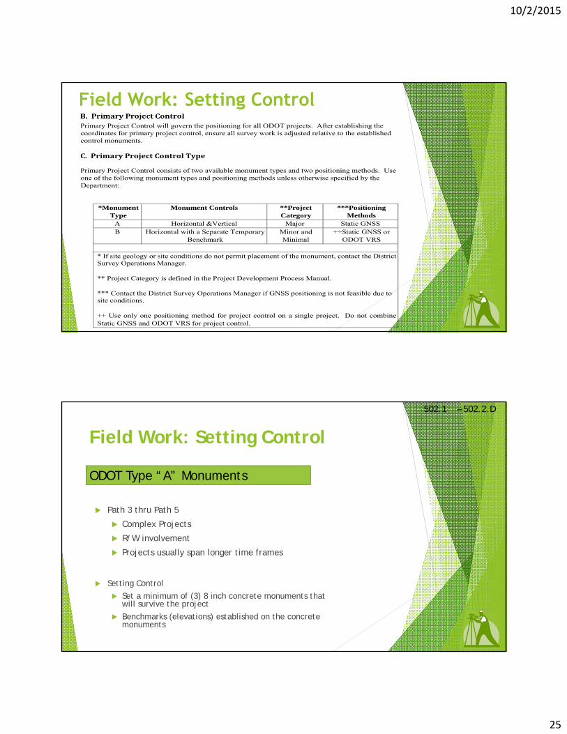
B.PrimaryProjectControlPrimary Project Control will govern the positioning for all ODOT projects. After establishing the coordinates for primary project control, ensure all survey work is adjusted relative to the established control monuments.
C.PrimaryProjectControlType
Primary Project Control consists of two available monument types and two positioning methods. Use one of the following monument types and positioning methods unless otherwise specified by the Department:
*Monument
Type Monument Controls **Project
Category ***Positioning
Methods A Horizontal &Vertical Major Static GNSS B Horizontal with a Separate Temporary
Benchmark Minor and Minimal
++Static GNSS or ODOT VRS
* If site geology or site conditions do not permit placement of the monument, contact the District Survey Operations Manager.
** Project Category is defined in the Project Development Process Manual.
*** Contact the District Survey Operations Manager if GNSS positioning is not feasible due to site conditions.
++ Use only one positioning method for project control on a single project. Do not combine Static GNSS and ODOT VRS for project control.
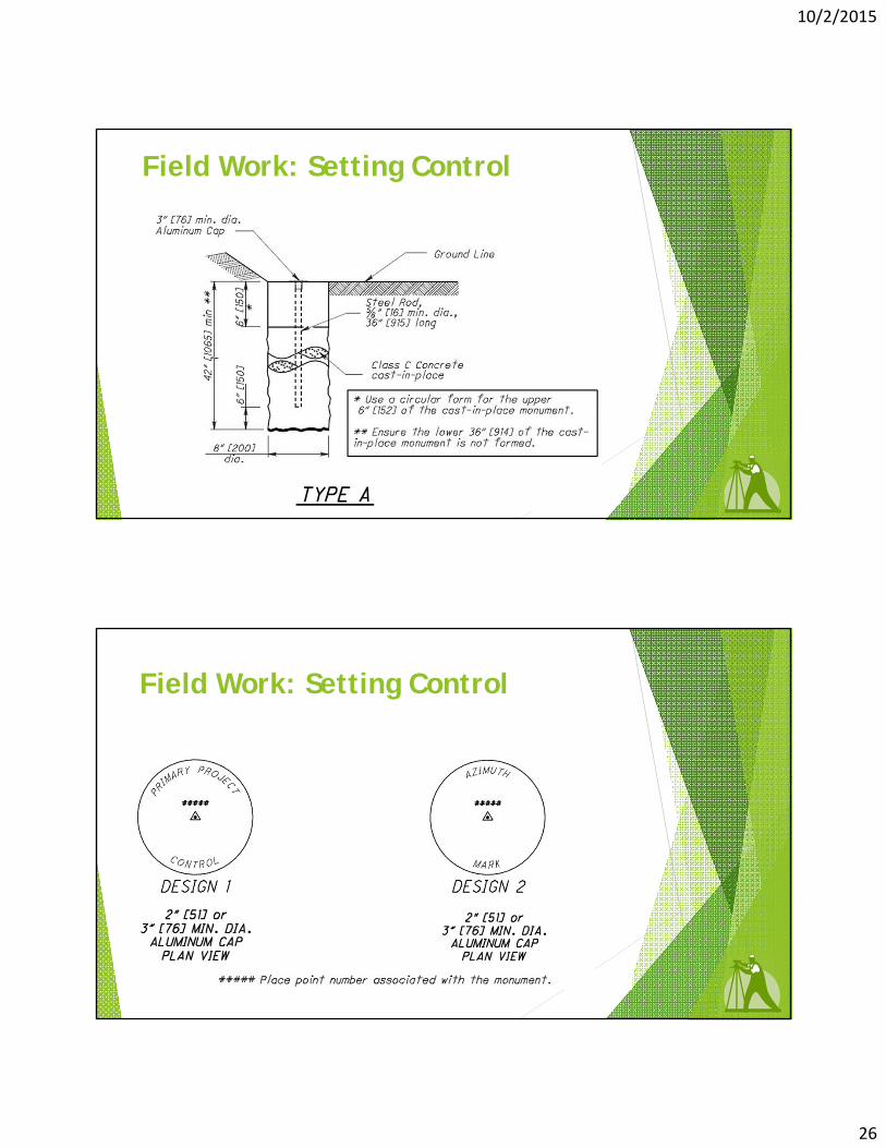
Field Work: Setting Control
502.1 – 502.2.D
ODOT Type “A” Monuments
Setting Control
Set a minimum of (3) 8 inch concrete monuments that will survive the project
Benchmarks (elevations) established on the concrete monuments
Path 3 thru Path 5
Complex Projects
R/W involvement
Projects usually span longer time frames
10/2/2015
26
Field Work: Setting Control
Field Work: Setting Control
10/2/2015
27
Field Work: Setting Control
3/4” Rebar with 3-1/4” Aluminum Cap
5/8” Rebar with Plastic Cap
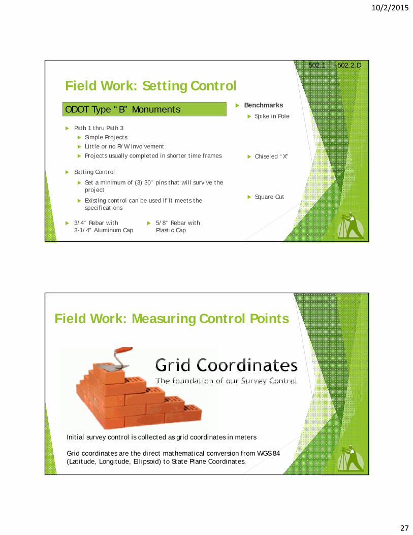
Benchmarks
Spike in Pole
Chiseled “X”
Square Cut
Setting Control
Set a minimum of (3) 30” pins that will survive the project
Existing control can be used if it meets the specifications
502.1 – 502.2.D
ODOT Type “B” Monuments
Path 1 thru Path 3
Simple Projects
Little or no R/W involvement
Projects usually completed in shorter time frames
Field Work: Measuring Control Points
Initial survey control is collected as grid coordinates in meters
Grid coordinates are the direct mathematical conversion from WGS 84 (Latitude, Longitude, Ellipsoid) to State Plane Coordinates.

10/2/2015
28
Field Work: Measuring Control Points
Depending on the size of the job and number of control points to be set, the horizontal positioning of the control normally only takes a few hours.
Leveling is typically performed on the control points to establish precise elevations.
We can also start our topographic mapping at this time (before control is formally established). As long as the control points are processed and entered into a Trimble Business Center project as Survey Control before the data collector files are imported, the data automatically adjusts to the control points.
Field Work: Measuring Control PointsType “A” Monuments
F.StaticGNSSDataCollection
Collect a minimum of 3 sessions of static GNSS data consisting of at least 4 hours per session for each primary project control monument. Ensure the survey equipment is removed and reinstalled over the monument between sessions. Ensure proper GNSS survey planning to achieve the required data quality as outlined in this specification. Consider the following when planning the GNSS survey: positional dilution of precision (PDOP), number of satellites, mask angle, collection rate, multipath, solar activity, etcetera.
G.StaticGNSSDataProcessing
Process the collected data to determine the Northing, Easting, and Elevation (Orthometric Height) for each session using National Geodetic Survey‟s OPUS (Online Positioning User Service). Use the rapid or precise ephemeris only. Ensure the correct antenna height, make, and model are utilized. Use the same three base stations when processing a primary project control point in OPUS. The user must manually select the base stations to be used in the OPUS processing.

10/2/2015
29
Field Work: Measuring Control PointsType “B” Monuments
H.ODOTVRSDataCollection
Collect the Northing, Easting, and Elevation coordinates using 5 second observations at a 1 second epoch rate. Collect a minimum of 5 observations for each project control monument. Note: More than 5 observations may be required to meet the minimum RMSE requirements specified below. Ensure the survey equipment is removed and reinstalled over the monument between sessions. Consider the following when planning and performing VRS surveys: positional dilution of precision (PDOP), number of satellites, mask angle, multipath, solar activity, etcetera.
Field Work: Measuring Control Points
Eliminate centering error
Take (4) shots, rotating the rod 90 degrees after each observation
Eliminate bad initializations
Physically break initialization between sets by turning the antenna upside-down or covering the antenna
Eliminate repeat site visits
(3) sets or (12) observations generally provides enough data to satisfy the RMSE requirements
502.1 – 502.2.D502.2.E – 502.2.H

10/2/2015
30
VERTICAL CONTROL
60
10/2/2015
31
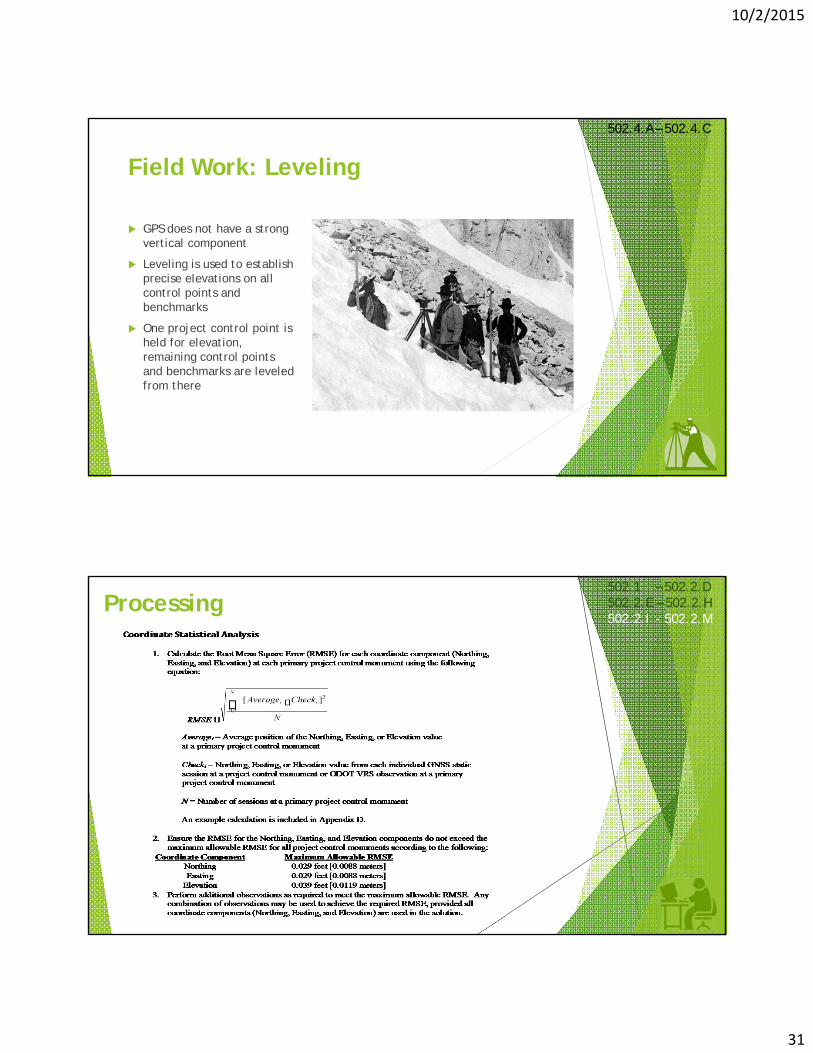
Field Work: Leveling
502.4.A – 502.4.C
GPS does not have a strong vertical component
Leveling is used to establish precise elevations on all control points and benchmarks
One project control point is held for elevation, remaining control points and benchmarks are leveled from there
Processing502.1 – 502.2.D502.2.E – 502.2.H502.2.I - 502.2.M

10/2/2015
32
Processing
J.PrimaryProjectControlMonumentHorizontalCoordinatesThe Northing and Easting primary project control monument coordinates are determined by taking the average of each coordinate component from the OPUS or ODOT VRS solutions that meet the RMSE requirements as specified in Section 502.2 I.
K.PrimaryProjectControlMonumentVerticalCoordinatesEstablish the elevations of primary project control monuments or their associated temporary bench marks by differential leveling. Refer to section 502.4 for leveling procedures. Differential leveling for primary project control monuments and temporary benchmarks will originate from, and close on, the primary project control monument closest to the center of the project.
Hold the elevation calculated from the vertical component of the OPUS or ODOT VRS solutions for theprimary project control monument closest to the center of the project. Ensure the elevations for the primarycontrol monument meet the RMSE requirements as specified in Section 502.2 I. As a check, compare theleveled elevations to the GNSS determined elevations from Section 502.2 I. Highlight any differences thatexceed 0.10 U.S. Survey Foot and contact the District Survey Operations Manager immediately to determinea course of action prior to performing any additional work.
Processing
L.SecondaryandTemporaryProjectControlSecondary and Temporary project control for surveying or construction purposes are to be positioned relative to the primary project control. Establish a monument type sufficient to ensure stability for the anticipated duration of project or task to be performed. Establish secondary and temporary project control at an accuracy to ensure conformance to the project plans.
M.ProjectScaleFactorIf a project scale factor is required, use the following method for establishing the combined scale factor:
1. If Static GNSS is used to determine the positions for primary project control monuments, use the average of the OPUS calculated combined scale factors for the monument closest to the center of the project. Ensure the scale factor is calculated from OPUS solutions that meet the RMSE requirements. Scale the project about the origin of the coordinate system (0,0).
If VRS is used to position primary project control monuments, perform a 20 minute static observation on the monument closest to the center of the project. Submit the static session to OPUS-RS to obtain the combined scale factor. Scale the project about the origin of the coordinate system (0,0) using the combined scale factor. Ensure coordinates and elevations ob
10/2/2015
33
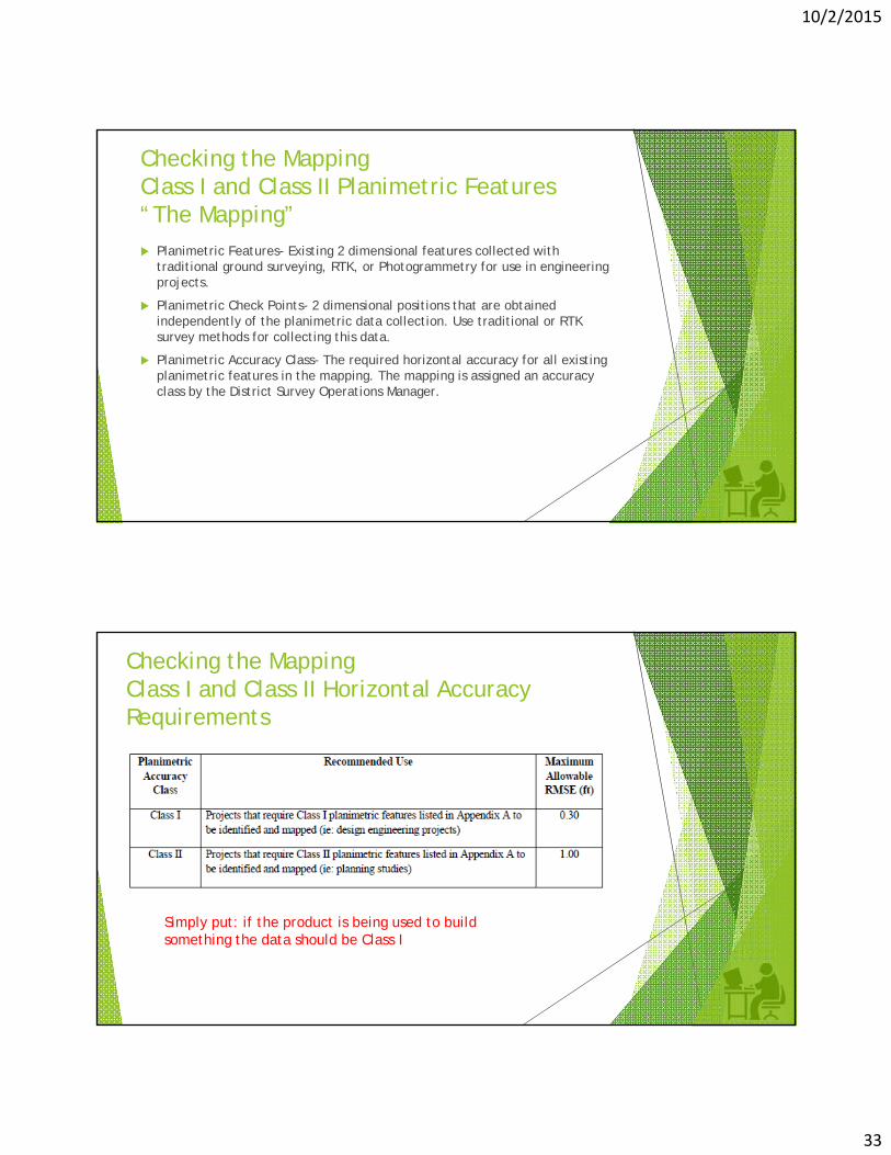
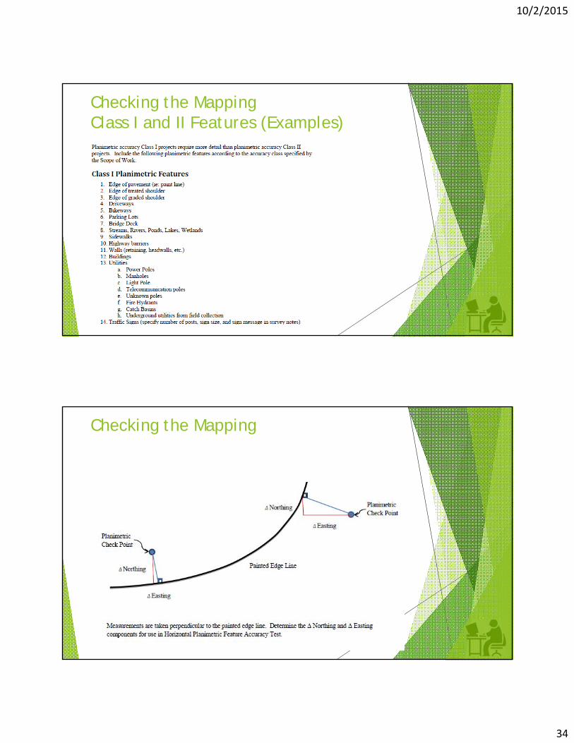
Checking the MappingClass I and Class II Planimetric Features“The Mapping” Planimetric Features- Existing 2 dimensional features collected with
traditional ground surveying, RTK, or Photogrammetry for use in engineering projects.
Planimetric Check Points- 2 dimensional positions that are obtained independently of the planimetric data collection. Use traditional or RTK survey methods for collecting this data.
Planimetric Accuracy Class- The required horizontal accuracy for all existing planimetric features in the mapping. The mapping is assigned an accuracy class by the District Survey Operations Manager.
Checking the MappingClass I and Class II Horizontal Accuracy Requirements
Simply put: if the product is being used to build something the data should be Class I
10/2/2015
34
Checking the MappingClass I and II Features (Examples)
Checking the Mapping
10/2/2015
35
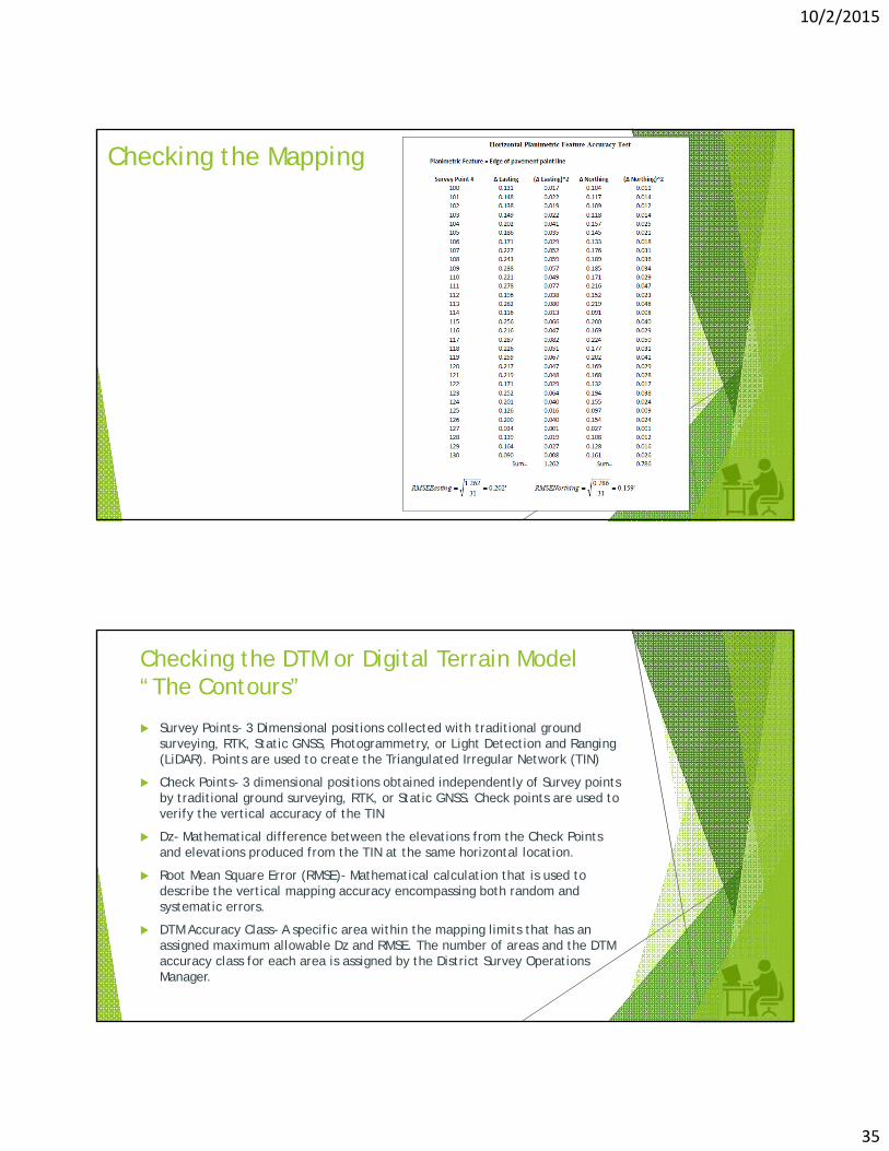
Checking the Mapping
Survey Points- 3 Dimensional positions collected with traditional ground surveying, RTK, Static GNSS, Photogrammetry, or Light Detection and Ranging (LiDAR). Points are used to create the Triangulated Irregular Network (TIN)
Check Points- 3 dimensional positions obtained independently of Survey points by traditional ground surveying, RTK, or Static GNSS. Check points are used to verify the vertical accuracy of the TIN
Dz- Mathematical difference between the elevations from the Check Points and elevations produced from the TIN at the same horizontal location.
Root Mean Square Error (RMSE)- Mathematical calculation that is used to describe the vertical mapping accuracy encompassing both random and systematic errors.
DTM Accuracy Class- A specific area within the mapping limits that has an assigned maximum allowable Dz and RMSE. The number of areas and the DTM accuracy class for each area is assigned by the District Survey Operations Manager.
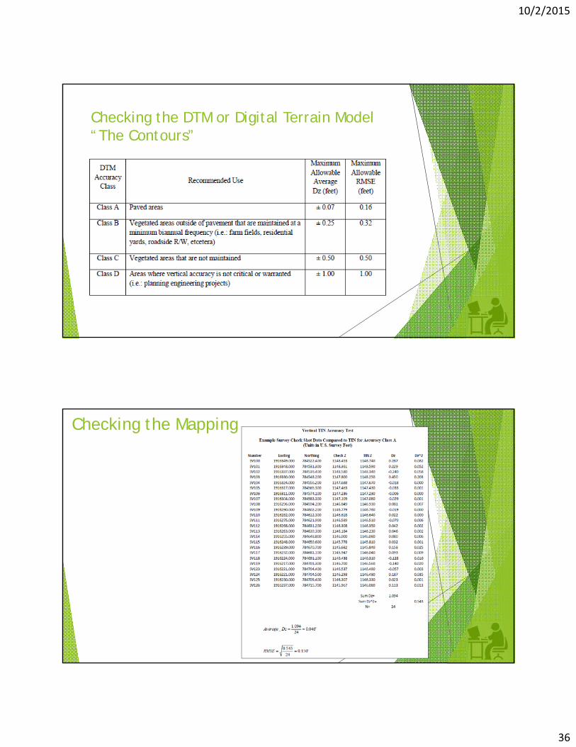
Checking the DTM or Digital Terrain Model “The Contours”
10/2/2015
36
Checking the DTM or Digital Terrain Model “The Contours”
Checking the Mapping

10/2/2015
37
Deliverables502.1 – 502.2.D502.2.E – 502.2.H502.2.I - 502.2.M502.2.N
Furnish the following deliverables:
1. Surveyor’s Certification Statement. A standard form is included in Appendix F. 2. A table that includes primary project control coordinates and azimuth mark
coordinates. Include the following in the table: a. Point Number b. Point Description c. Monument Type d. Positioning Method e. Grid Coordinates
a. Northing (meters) b. Easting (meters)
f. If applicable, Scaled Coordinates a. Northing (U.S. survey feet) b. Easting (U.S. survey feet)
g. If applicable, the Project Combined Scale Factor and associated monument h. Type A primary project control orthometric heights (U.S. survey feet) i. Temporary Benchmark number, description, and orthometric height listed with
each Type B primary control monument
1. NGS OPUS data sheets if used in the solutions 2. NGS OPUS-RS data sheets if used to obtain a scale factor 3. Statistical analysis for each primary project control monument and azimuth mark(s). (See
example, Appendix D) 4. Native survey data files in Trimble RAW or RINEX 2.0 format
Deliverables

10/2/2015
38
Deliverables
Surveyor’s Certification for Primary Project Control
I, (Surveyor’s Name) do hereby certify that the Primary Project Control for (name of project) were constructed and established in
accordance with the Ohio Department of Transportation’s Survey and Mapping Specifications, dated (last revision date) for a (major or
minor and minimal) project and meet the accuracy requirements as set forth therein. All observation data and RMSE calculations are on
file and available at the request of the Ohio Department of Transportation.
__________________________ __________
Signature Date Surveyor’s Seal
Surveyor’s Printed Name
And Registration Number
Every Project is Unique
Know the ODOT Survey and Mapping Specifications
Get a clearly defined Scope of Services from the District Planning and Engineering Department
Get in touch with the District Survey Operations Manager early in the project. They are there to help you.
Submit your Survey Quality Control report to the District as soon as you are done with the mapping. Make sure the Survey Operations Manager is included on the correspondence.
Being proactive and making sure you have the line of communication open with the Survey Operations Manager will save you a lot of head aches as the project progresses through design and Right-of-Way acquisition.our District’s Survey Operations Manager

10/2/2015
39
REMEMBER! YOUR MAPPING AND CONTROL IS THE FOUNDATION OF THE PROJECT.
IT IS IMPORTANT INFORMATION!
IT NEEDS TO BE CORRECT!