mef e-nni support
TRANSCRIPT

MEF E-NNI SupportVersion 1
Stephen HaddockMay 1, 2009May 1, 2009
802.1 Interim, Pittsburgh
May 2009 802.1 meeting, Pittsburgh1

Table of Contents
• Metro Ethernet Forum background• Hairpin Switching• Virtual UNI• Potential Provider Bridging modifications
May 2009 802.1 meeting, Pittsburgh2

M t Eth t F b k dMetro Ethernet Forum background
May 2009 802.1 meeting, Pittsburgh3

MEN, UNI, and EVC, ,
UNI BCE
Metro Ethernet Network (MEN) or Carrier Ethernet Network (CEN) used interchangeably for Provider or Operator owned networks that
UNI AUNI B
CE MEN
for Provider or Operator owned networks that provide connectivity services to customers.
UNI CCE
The MEF specifies the services provided by the MEN, the interfaces to the MEN, and the attributes that characterize the services and interfaces. The MEF does not specify the technology used within the MEN to implement the services. If the MEN is implemented with 802.1 technology then the MEN is equivalent to a Provider Bridged Network (or possibly Provider Backbone Bridged Network) in 802.1 terminology.
May 2009 802.1 meeting, Pittsburgh4

MEN, UNI, and EVC, ,
UNI BCE
User Network Interface (UNI) is theUNI A
UNI B
CE MEN
User Network Interface (UNI) is the demarcation between the MEN and Customer Equipment (CE) in the customer network.
UNI CCE
The physical medium at the UNI is a full-duplex 802.3 LAN. The frame format at the UNI is an untagged or C-tagged Ethernet frame. UNIs may be:
• “All-to-One-Bundling” where all customer frames are mapped to a single serviceAll to One Bundling where all customer frames are mapped to a single service instance. If the MEN uses 802.1ad technology then this is a Port-based service interface.• “Service Multiplexing” where customer frames are mapped to a service instance (or filtered) based on the C-VID If the MEN uses 802 1ad technology then this is a
May 2009 802.1 meeting, Pittsburgh5
filtered) based on the C VID. If the MEN uses 802.1ad technology then this is a C-tagged service interface.

MEN, UNI, and EVC, ,
UNI BCE
UNI AUNI B
CE MEN
Ethernet Virtual Connection (EVC) is an association of UNIs such that any ingress customer frame mapped to an EVC at a UNI
UNI CCE
cus o e e pped o VC Umay be delivered to any or all other UNIs that have mappings to the same EVC.
EVCs may be point-to-point, multipoint-to-multipoint, or rooted-multipoint.
If the MEN uses 802.1ad technology then the EVC is a service instance implemented by an S-VLAN and identified by an S-VID.
May 2009 802.1 meeting, Pittsburgh6

Service Provider, Operators, and E-NNI, p ,External Network Network Interface (E-NNI) is a reference point representing the boundary between two Operator MENs th t t d t d i i t ti d i
UNI AUNI B
CE
that are operated as separate administrative domains.
UNI DE-NNIUNI A
CE
CE
UNI DE NNI
Op AMEN
Op BMEN
UNI CCE
MEN MEN
In the MEF model there is a Service Provider responsible for the end-to-end service offered to a customer. The Service Provider may contract with one or more Operators, each responsible for a MEN, to realize the service. The Service Provider may (or may not) be the same business entity as one of the Operators
May 2009 802.1 meeting, Pittsburgh7
same business entity as one of the Operators.

E-NNI and OVCOperator Virtual Connection (OVC) ) is an association of external interfaces (UNIs or E-NNIs) of a single Operator MEN such that any ingress customer frame mapped to an OVC at one interface may be delivered to any or all other interfaces that have mappings to the same OVC.
UNI AUNI B
CE
UNI DE-NNI
CE
CE
Op AMEN
Op BMEN
The physical medium at the E-NNI is a full-duplex 802.3 LAN. The frame format at the E-NNI i S t d 802 3 f Th S VID i ( hl ki ) i id tifi th t ll th
OVC OVCEVC
is an S-tagged 802.3 frame. The S-VID is (roughly speaking) a service identifier that allows the operator on either side of the E-NNI to map frames to the appropriate OVC End Point.
An EVC is an end-to-end (UNI-to-UNI) service instance . An OVC is a local (to one Operator MEN) i i t I th i t l ti hi ithi i O t
May 2009 802.1 meeting, Pittsburgh8
MEN) service instance. In many cases there is a one-to-one relationship within a given Operator MEN between an OVC and an EVC, however this is not true in all cases.

H i i S it hi t E NNIHairpin Switching at E-NNI
May 2009 802.1 meeting, Pittsburgh9

OOF-UNIs
UNI ECE
Op BMEN
UNI AUNI B
CE E-NNI
MEN
CE
CE
UNI DSP/Op AMEN
In this case the Service Provider is the same as Operator A, and is providing a multipoint EVC to
Op CMEN
E-NNI
p , p g pa customer with several sites. Two of the customer sites, UNI D and UNI E, are “Out-of-Footprint” (OOF) meaning they are not reachable by the Operator A MEN. Therefore the SP obtains a point-to-point OVC in Operator B’s MEN and in Operator C’s MEN to connect each OOF-UNI to an E-NNI.
May 2009 802.1 meeting, Pittsburgh10

OOF-UNIs and Hairpin Switching
UNI A
p g
UNI BCE
UNI DE-NNI UNI ECE
CE
CE
SP/Op AMEN
Op BMEN
Same scenario except each OOF-UNI is reachable through MEN B. Therefore the SP obtains two point-to-point OVCs in Operator B’s MEN to connect each OOF-UNI to the E-NNI. In theory the SP could obtain a single multipoint OVC in Operator B’s MEN, however for business purposes th SP d t t t di l d l t t O t B f th d t il f th i b ithe SP does not want to disclose or delegate to Operator B any of the details of the service being provided to the customer.
In MEN B these are two completely unrelated OVCs. At the E-NNI frames to/from each OOF-UNI id tifi d b diff t S VID l B t i MEN A th f t th OVCUNI are identified by different S-VID values. But in MEN A these frames map to the same OVC. A particularly problematic case is where a frame from UNI E destined to UNI D needs to be received by MEN A at the physical port that is the E-NNI, and transmitted on the same physical port but with a different S-VID. This is “hairpin switching.” To make this operate exactly as the
i h f t /f UNI E d UNI D i t MEN diff t t MEN
May 2009 802.1 meeting, Pittsburgh11
previous case where frames to/from UNI E and UNI D came into MEN a on different ports, MEN A needs to use the S-VID value to create different virtual ports.

Comparison to EVB scenariop• Similarities to the Edge Virtual Bridging scenarios being discussed in
the Data Center Bridging Task Group:1. Both call for a solution where a bridge forwards packets between two entities that
are connected to the bridge through the same physical port.
• Differences from EVB:1 Use of the S tag as the virtual port selector1. Use of the S-tag as the virtual port selector.
a) In the MEF E-NNI environment, the presence of the S-tag is a given making it the logical choice. b) Using an additional tag would not provide any benefit, and would unnecessarily require the OOF
network to treat OVCs that go to a virtual port at the E-NNI differently from other OVCs.
2 No local switching, including multicast replication2. No local switching, including multicast replication.In the Data Center Bridging EVB environment there is a desire not to have the bridge with the virtual ports
do multicast replication for the virtual ports (and thus send multiple copies of the multicast packet on the same physical link). Rather there is a desire to devise a system that allows multicast replication to be done closer to the other end of the virtual link. In the MEF environment this is explicitly not desirable, because to do so is antithetical to the premise that the OOF network operator knows nothingdesirable, because to do so is antithetical to the premise that the OOF network operator knows nothing about the details of the service, including the full connectivity.
3. No “Port Expander”.In the DCB EVB environment there is some kind of device that multiplexes traffic from virtual interfaces on
to a single physical link connecting to the bridge implementing the virtual ports. In the MEF scenario th i h d i Th OOF t k d t di ti i h UNI th t t t i t l t tthere is no such device. The OOF network does not distinguish UNIs that connect to virtual ports at the E-NNI from UNIs that do not. The OOF network is completely unaware of the port virtualization.
May 2009 802.1 meeting, Pittsburgh12

Possible solutions: Hairpin Switchingp g1. Expand VLAN-tagging shim (6.9) so
that it may present multiple Virtual Bridge Ports to the MAC Relay similar
Relay
EM
S-Comp
Bridge Ports to the MAC Relay, similar to the Provider Instance Port (6.10) for Backbone Edge Bridges.
2 Define a new type of Provider Edge
NNI
MEN
2. Define a new type of Provider Edge Bridge that is similar to the current PEB except uses S-Components to demultiplex based on S-VID where the
S-CompS-Comp
MEN
ENNIdemultiplex based on S VID where the
current PEB uses C-components to demultiplex based on C-VID.
3. Expand VLAN-tagging shim (6.9) so the
I
3. Expand VLAN tagging shim (6.9) so the S-VID translation table supports many-to-one S-VID translation, and add functionality for local switching and y gmulticast replication.
May 2009 802.1 meeting, Pittsburgh13

Vi t l UNI t E NNIVirtual UNI at E-NNI
May 2009 802.1 meeting, Pittsburgh14

Service Multiplexing OOF-UNIp g
UNI AUNI B
CE
UNI DE-NNIUNI A
CE
UNI D
SP/Op AMEN
Op BMEN
CE
MEN MEN
In this case the Service Provider is providing two (or more) EVCs to UNI D which is Out-of-Footprint The straight forward solution is for the SP to obtain an OVC per EVC from OperatorFootprint. The straight-forward solution is for the SP to obtain an OVC per EVC from Operator B and have Operator B perform the service multiplexing functionality as shown. The SP finds this solution undesirable for several reasons:1. Requires obtaining multiple OVCs from Operator B.2 Requires disclosing and delegating details of the service being provided to Operator B2. Requires disclosing and delegating details of the service being provided to Operator B.3. Requires coordinating with Operator B whenever there is a change in the number of EVCs
or attributes of the EVCs being provided at UNI D.
May 2009 802.1 meeting, Pittsburgh15
Virtual UNI (VUNI)( )
UNI AUNI B
CE
UNI DE-NNIUNI A
CE
UNI D
SP/Op AMEN
Op BMEN
CE
MEN MEN
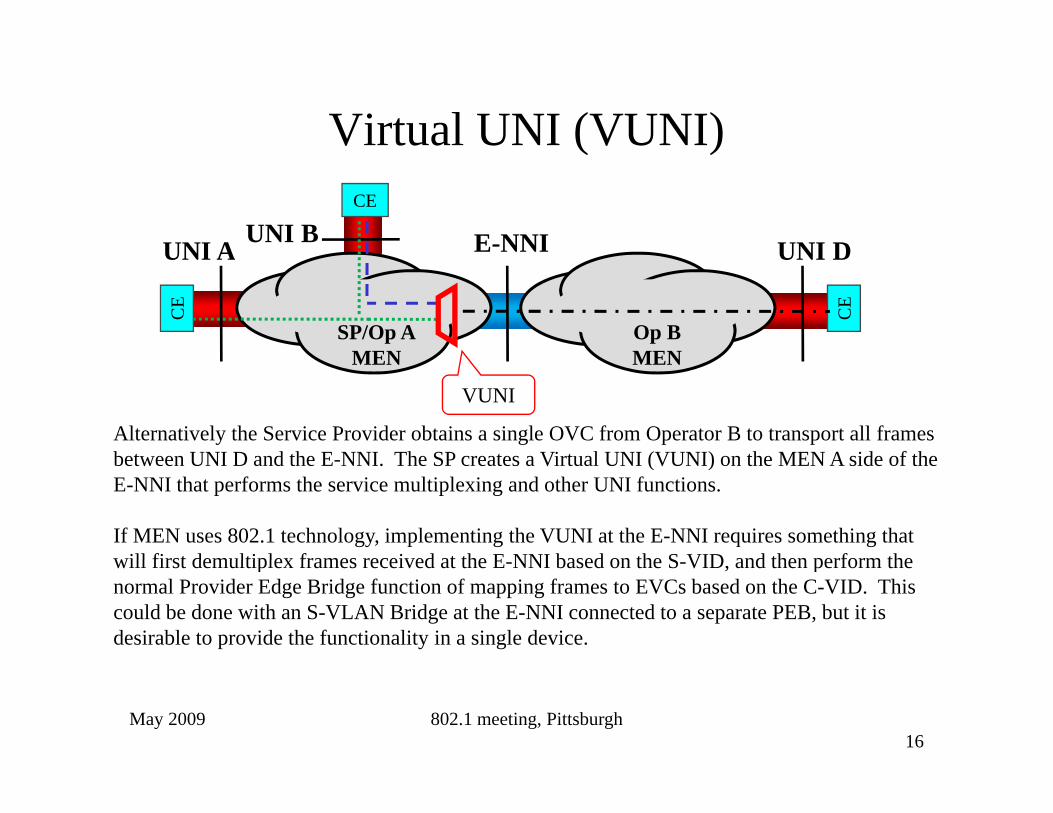
Alternatively the Service Provider obtains a single OVC from Operator B to transport all frames between UNI D and the E NNI The SP creates a Virtual UNI (VUNI) on the MEN A side of the
VUNI
between UNI D and the E-NNI. The SP creates a Virtual UNI (VUNI) on the MEN A side of the E-NNI that performs the service multiplexing and other UNI functions.
If MEN uses 802.1 technology, implementing the VUNI at the E-NNI requires something that will first demultiplex frames received at the E NNI based on the S VID and then perform thewill first demultiplex frames received at the E-NNI based on the S-VID, and then perform the normal Provider Edge Bridge function of mapping frames to EVCs based on the C-VID. This could be done with an S-VLAN Bridge at the E-NNI connected to a separate PEB, but it is desirable to provide the functionality in a single device.
May 2009 802.1 meeting, Pittsburgh16

Possible solutions: VUNI1. Create a demultiplexing interface
stack that is not part of a bridge (i h d
C-CompEcomponent (i.e. not attached to a
single MAC Relay). Each “Virtual Port” may attach to Bridge Ports on separate bridge C-Comp
S-Comp
MEN
ENNI
Bridge Ports on separate bridge components.
2. Define a new type of Provider Edge Bridge that is similar to the
p
Edge Bridge that is similar to the current PEB except adds an S-component to demultiplex based on the E-NNI S-VID with internal M
C-CompEon the E NNI S VID with internal
connections to Customer Edge Ports (for VUNI) or Customer Network Ports (for “normal” C-Comp
S-CompEN
S-CompNNI
(traffic and hairpin switching).
May 2009 802.1 meeting, Pittsburgh

Potential Provider Bridging modificationsmodifications
Evaluating the possible Hairpin Switching and VUNI solutions
May 2009 802.1 meeting, Pittsburgh18

Narrowing the solution spaceg p• Of the potential Hairpin solutions, #3 is least promising.
– Even without the VUNI functionality, achieving hairpin switching, multicast replication, and many-to-one S-VID translation makes the shim very complex.
– With VUNI functionality the shim would need to replicate all functions of a C-component in a Provider Edge Bridge, including the control protocols.
• Hairpin solution #1 can be generalized to VUNI #1• Hairpin solution #1 can be generalized to VUNI #1.– Hairpin solution #2 cannot accommodate the VUNI functionality, however
separating the multiplexer from a specific bridge component (as in VUNI solution #2) can accommodate both Hairpin switching and the VUNI.) p g
• VUNI solutions #1 and #2 are very similar– The distinction comes down to determining how a newly defined S-VID
multiplexer would differ from a full S-component.multiplexer would differ from a full S component.– For packet forwarding the S-component would be configured to behave
very much like (exactly like?) the multiplexer.– The primary difference between a full S-component and a multiplexer is p y p p
likely to be in things like control protocols and CFM.May 2009 802.1 meeting, Pittsburgh
19

A more detailed lookThis is the S-component that would normally be at an E-NNI, even if were not doing any hairpin
i hi f i
A C-component to perform the same functions at the “Virtual UNI” for a single customer service interface
VUNI
switching or VUNI functions. that the C-component of a Provider Edge Bridge would perform at a normal UNI.
MENS-Comp
MEN
VUNIC-Comp
E-NNIS-Comp
ENNIVUNI
C-Comp
I
S-component (or new demultiplexing entity) dedicated to demultiplexing ingress frames from E-NNI based on the S-VID, and tagging egress frames to the E NNI with the appropriate C VID
May 2009 802.1 meeting, Pittsburgh20
frames to the E-NNI with the appropriate C-VID.

Common Elements
• Both solutions demultiplex frames arriving at the E-NNI to different internal links and thus to different Bridge Portsdifferent internal links, and thus to different Bridge Ports on the MEN S-component, based on the E-NNI S-VID. 1. This allows the normal relay function of the MEN S-component to
f b th h i i it hi d lti t li ti ith t h iperform both hairpin switching and multicast replication without echoing any frames back to their source.
2. This allows frames destined for a VUNI to be directed to a C-component.3 This allows normal operation of control protocols (e g RSTP MVRP) on3. This allows normal operation of control protocols (e.g. RSTP, MVRP) on
the MEN S-component.
May 2009 802.1 meeting, Pittsburgh21