memristor-based analog neuromorphic …d-scholarship.pitt.edu/20918/1/liu_etd2014.pdf ·...
TRANSCRIPT

MEMRISTOR-BASED ANALOG NEUROMORPHIC COMPUTING ENGINE DESIGN
AND ROBUST TRAINING SCHEME
by
Beiye Liu
B.S., Southeast University, Nanjing, China, 2011
Submitted to the Graduate Faculty of
Swanson School of Engineering in partial fulfillment
of the requirements for the degree of
Master of Science
University of Pittsburgh
2014

ii
UNIVERSITY OF PITTSBURGH
SWANSON SCHOOL OF ENGINEERING
This thesis was presented
by
Beiye Liu
It was defended on
March 18,2014
and approved by
Yiran Chen, PhD, Assistant Professor, Department of Electrical and Computer Engineering
Hai Li, PhD, Assistant Professor, Department of Electrical and Computer Engineering
Zhi-Hong Mao, PhD, Associate Professor,
Department of Electrical and Computer Engineering and Bioengineering
Mingui Sun, PhD, Professor,
Department of Neurological Surgery, Bioengineering and Electrical Engineering
Thesis Advisor: Yiran Chen, PhD, Assistant Professor,
Department of Electrical and Computer Engineering

iii
Copyright © by Beiye Liu
2014

iv
MEMRISTOR-BASED ANALOG NEUROMORPHIC COMPUTING ENGINE
DESIGN AND ROBUST TRAINING SCHEME
Beiye Liu, M.S.
University of Pittsburgh, 2014
The invention of neuromorphic computing architecture is inspired by the working mechanism
of human-brain. Memristor technology revitalized neuromorphic computing system design by
efficiently executing the analog Matrix-Vector multiplication on the memristor-based crossbar
(MBC) structure. In this work, we propose a memristor crossbar-based embedded platform for
neuromorphic computing system. A variety of neural network algorithms with threshold
activation function can be easily implemented on our platform. However, programming the
MBC to the target state can be very challenging due to the difficulty to real-time monitor the
memristor state during the training. In this thesis, we quantitatively analyzed the sensitivity of
the MBC programming to the process variations and input signal noise. We then proposed a
noise-eliminating training method on top of a new crossbar structure to minimize the noise
accumulation during the MBC training and improve the trained system performance, i.e., the
pattern recall rate. A digital-assisted initialization step for MBC training is also introduced to
reduce the training failure rate as well as the training time. We also proposed a memristor-based
bidirectional transmission exhibition/inhibition synapse and implemented neuromorphic
computing demonstration with our proposed synapse. Experiment results show that the
proposed design has high tolerance on process variation and input noise. Different benefits of
MBC system and new synapse-based system will be compared in our thesis.

v
TABLE OF CONTENTS
PREFACE ..................................................................................................................................... X
1.0 INTRODUCTION ........................................................................................................ 1
2.0 BACKGROUND .......................................................................................................... 3
2.1 MEMRISTOR BASICS ...................................................................................... 3
2.2 MBC-BASED COMPUTING ............................................................................. 4
2.3 TRAINING METHOD OF MBC ....................................................................... 5
3.0 NOISE-ELIMINATING TRAINING ........................................................................ 7
3.1 IMPACTS OF DEVICE VARIATION AND NOISE ...................................... 7
3.2 NOISE SENSITIVITY OF MBC TRAINING ................................................ 10
3.3 NOISE-ELIMINATING TRAINING SCHEME............................................ 10
4.0 DIGITAL-ASSISTED INITIALIZATION .............................................................. 13
4.1 BASIC IDEA ...................................................................................................... 13
4.2 DIGITALIZATION OF WEIGHT MATRIX ................................................ 14
5.0 TRAINING QUALITY EVALUATION ................................................................. 16
5.1 NOISE ELIMINATION .................................................................................... 16
5.2 DIGITAL-ASSISTED INITIALIZATION ..................................................... 17
5.3 CASE STUDY .................................................................................................... 20
6.0 NEW MEMRISTOR-BASED SYNAPSE DESIGN ............................................... 24
6.1 BIOLOGY INSPIRED SYNAPSE DESIGN................................................... 24
6.2 EXCITATION/INHIBITION TRANSMISSION ........................................... 26
6.3 SYNAPSE BASED NEUROMORPHIC COMPUTING SYSTEM .............. 30

vi
6.3.1 System Architecture ...................................................................................... 30
6.4 SYSTEM EVALUATGION .............................................................................. 31
6.4.1 Robustness ...................................................................................................... 31
6.4.2 Capacity Analysis .......................................................................................... 32
6.5 COMPARISON BETWEEN CROSSBAR AND SYNAPSE BASED
ARCHITECTURE ............................................................................................................. 35
7.0 CONCLUSION ........................................................................................................... 37
BIBLIOGRAPHY ....................................................................................................................... 38

vii
LIST OF TABLES
Table 1, Experiment Setup ............................................................................................................ 16
Table 2, Training Failure Rate ...................................................................................................... 22
Table 3, Excitation/Inhibition synapse Truth Table ..................................................................... 28

viii
LIST OF FIGURES
Figure 1. (a) Metal-oxide memristor [10]. (b) Resistance distributions of MLC memristor. ......... 3
Figure 2. Conceptual overview of neural network [3]. ................................................................... 4
Figure 3. Training with (a) memristor variation. (b) voltage noise. (c) reference memristors. ...... 8
Figure 4. Training quality with ideal memristor and memristor with different variations. ............ 9
Figure 5. Training process with noise. ............................................................................................ 9
Figure 6. Noise elimination mechanism. ...................................................................................... 11
Figure 7. Digital-assisted Initialization. ........................................................................................ 14
Figure 8. Noise-eliminating training (a) with signal noise; (b) with memristor variation ............ 17
Figure 9. Train speed. (a) Ideal case. (b) 𝜹𝒗 = 𝟎. 𝟑. (c) 𝜹𝒗 = 𝟎. 𝟏𝟓. (d) variation and noise. .. 18
Figure 10. The impact of initialization on total training time. ...................................................... 19
Figure 11. 3-layer network recall rate. (a) Standard patterns; (b) Successful recognize rate. ...... 21
Figure 12. Comparisons of overall training time. ......................................................................... 22
Figure 13, Schematic of Neurons Connected with Memristor-based Bidirectional Synapse ....... 25
Figure 14, Simulation result of neuron-synapse oscillating ring .................................................. 26
Figure 15, Excitation/Inhibition synapse. ..................................................................................... 27
Figure 16, Information Collecting Neuron Demo. ........................................................................ 28
Figure 17, Simulation of Information Collecting Neuron Demo. ................................................. 29
Figure 18, (a) Standard patterns; (b) Noised patterns; (c) Noised input (black bars) VS output. . 31
Figure 19, The Impact of Memristor Variations on the Probability of Failure (Pf) ..................... 32
Figure 20, Failure Rate of Hopfield Network under Different Patterns and Process Variation. .. 33

ix
Figure 21, Increasing the Network Size VS Pf. ............................................................................ 34
Figure 22, Synapse-based Image Smoothing Processor. .............................................................. 35
Figure 23, Synapse-based Image Smoothing Processor Area Cost. ............................................. 36

x
PREFACE
Over the past three years of studying at University of Pittsburgh, I have learned a tremendous
amount. Here, I want to thank my supervisor, Professor Yiran Chen, for all his support and
guidance during my Master Program. Also, I am very thankful to Dr. Hai Li, Dr. Mingui Sun and
Dr. Zhi-hong Mao for their kindly consenting to be my committee members. I appreciate all of the
extremely helpful suggestion discussion. I thank all the lab members in Dr. Chen’s research group
as well as all my friends here in University of Pittsburgh.

1
1.0 INTRODUCTION
The explosive growth of the functional variety of modern embedded systems leads to the
emergence of Multiprocessor System-on-Chip (MPSoC) [7]. However, the functionalities of
various processing elements on a MPSoC are usually determined at system architect and design
stages. Any changes beyond the system capability may incur architecture change, circuit redesign
or even new chip fabrication with high cost. The application of programmable elements, such as
GPU, mitigates the redesign cost, but achieving the system reconfigurability and power efficiency
simultaneously still remains as a challenge [11].
The emerging of neuromorphic computing system successfully addresses this challenge by
providing functionality reconfiguration as well as low power consumption, especially for the
computational intensive applications. Although many neuromorphic computing algorithms have
been proposed for many applications like signal processing, pattern recognition, surveillance etc.
limited progress was made on the VLSI realization of neuromorphic computing systems [1]. Based
on the prediction of Prof. Leon Chua in 1972 [2]. HP Labs discovered a memristor device. A
memristor can record the historical profile of the electrical excitations applied on it and incur
corresponding resistance change [12]. The similarity between this memristive effect and biologic
synaptic have motivated many breakthroughs in the design of the neuromorphic hardware systems
[4, 5]. A lot of memristor based synapse designs have been proposed for cognitive computing
tasks. For higher connection density and efficiency memristor-based crossbar (MBC) structure is

2
recently introduced to improve the execution of the Matrix-Vector multiplications, which is one
of the most common operations in the mathematic representation of artificial neural network
(ANN) [6, 3]. However, there are three major technical challenges in such designs: 1) Due to the
difficulty of real-time monitoring the memristor state, the off-line training, e.g., directly
programming the resistance of a single memristor to the target value is unlikely possible [4]; 2)
The input vector-based iterative training methods, however, usually suffer from the long
convergence time [3]; and 3) The input signal noise and process variations severely affect the
training efficiency and reliability.
In this work, we quantitatively analyzed the sensitivity of the MBC programming to the process
variations and input signal noise. We then proposed a noise-eliminating training method with the
corresponding modified crossbar structure to minimize the noise accumulation during the MBC
training and enhance the trained system performance, i.e., the pattern recognition rate. A digital-
assisted initialization step for MBC training is also introduced to reduce the training failure rate as
well as the training time. Experimental results show that our technique can significantly improve
the performance and training time of neuromorphic computing system by up to 39.35% and
23.33%, respectively.
At the same time, we also conduct research on more flexible memristor-based synapse design that
will give us better efficiency on certain cognitive computing tasks. The design is inspired by
bidirectional biological synapse structure. The memristor is used as gate voltage controller to
dynamically control the current going through the transistor, which represent “synaptic” behavior.

3
2.0 BACKGROUND
2.1 MEMRISTOR BASICS
Figure 1(a) depicts an ion migration filament model of HfOx memristors [9]. A HfOx layer is
sandwiched between two metal electrodes TE (top electrode) and BE (bottom electrode).
Figure 1. (a) Metal-oxide memristor [10]. (b) Resistance distributions of MLC memristor.
During the reset process, the memristor switches from low resistance state (LRS) to high
resistance state (HRS). The oxygen ions migrate from the electrode/oxide interface and recombine
with the oxygen vacancies. A partially ruptured conductive filament region with a high resistance
per unit length Roff is formed on the left of the conductive filament region with a low resistance per
unit length Ron as shown in Figure 1(a). During the set process, the memristor switches HRS to
LRS. The ruptured conductive filament region shrinks. We define L as the total thickness of the

4
oxide layer and h as the length of the ruptured conductive filament region, respectively. The
resistance of the memristor R can be calculated by [9][15]:
R= Roff h+ Ron(L-h). (1)
We note that the memristor resistance can be programmed to any arbitrary value by
applying a programming current with different pulse width or magnitude. Note that the memristor
resistance changes only when the applied voltage is above a threshold, e.g., Vwrth.
Figure 2. Conceptual overview of neural network [3].
2.2 MBC-BASED COMPUTING
Fig. 2 depicts a conceptual overview of a neural network. Two groups of neurons are connected
by a set of synapses. The output neurons collect the information from the input neurons through
the synapses and process them with certain activation function. The synapses apply different
weights (synaptic strengths) on the information during the transmission. In general, the
relationship between the activity patterns of the input neurons U and the output neurons Y can be
respectively illustrated as:
Yn=Wn×m×Um. (2)

5
Here the weight matrix Wn×m denotes the synaptic strengths between the two neuron groups. In
neuromorphic computing system, the Matrix-Vector multiplication represented in Eq. (2) is one of
the most frequent operations [10][14]. Because of the structural similarity, reconfigurable resistive
array, e.g., MBC is conceptually efficient to execute the Matrix-Vector multiplications [3]. During
the operation of MBC-based computing, U is mimicked by the input voltage vector applied on the
word-line (WL) of the MBC. Every memristor in the MBC is programmed to the resistance state
representing the weight of the corresponding synapse [17]. The current along every bit-line (BL)
of the MBC is collected and converted to the output voltage vector Y by the comparator circuit.
Please refer to the appendix for more details on the operation of the MBC-based neuromorphic
computing engine.
2.3 TRAINING METHOD OF MBC
The training of MBC is defined as the process of programming the resistances of the memristors
in the MBC to the value representing the connection matrix in Eq. (2). Training method is also
derived from the close-loop training algorithm of the weight matrix in ANN theory, e.g., gradient
descent training [8]. During the training process, the weight matrix W is updated iteratively until
the difference between the output y and the target output y* reaches the minimum. In each iteration,
W is adjusted based on the gradient of the output error |y-y*| as:
∆𝑤𝑖𝑗 = 𝜇 ∙ (𝜕(𝑦 − 𝑦 ∗)2
𝜕𝑤𝑖𝑗). (3)

6
Here wij is the element in the W connecting the neuron i and j, or the resistance of the memristor
at row i and column j in the MBC. ∆ wij is the change of wij during the iterations. μ is the training
rate. The choice of μ is discussed in [3].

7
3.0 NOISE-ELIMINATING TRAINING
3.1 IMPACTS OF DEVICE VARIATION AND NOISE
Process variation and signal noise are two major factors affecting the robustness of MBC-based
computing and training processes. Figure 3(a) shows an example of the output comparison step in
the MBC training process when a set of read voltage Vrd, 0, Vrd/2 is applied to the WLs of three
memristors R1 -- R3 in the same column. Here we assume the three memristors are all at HRS.
The ideal voltage on the BL shared by these three memristors should be Vrd/2. However, the device
non-uniformity and the input voltage fluctuation may cause the bias changes on the memristors.
For example, if the resistance of R1 is larger than that of R2, the voltage on the BL will be below
Vrd/2, as shown in Figure 3(a). Also, if the input voltages on the WL of R1 changes to Vrd + ∆V,
the voltage on the BL will be above Vrd/2, as shown in Figure 3(b). In both cases, the calculated
difference between the current output and the target output will be different from the ideal case.
Such deviation can be accumulated along with the training iterations. Together with the
fluctuations of the programming voltage and the process variations, it will cause the deviation of
the programmed memristor resistance from the ideal value during the programming step in the
MBC training process and finally affect the computation accuracy. We use an example to illustrate
the impacts of the process variation and input signal noise on the MBC training. A 64 x 64 MBC
is implemented to realize the synapse connection of a two-layer neural network.

8
Figure 3. Training with (a) memristor variation. (b) voltage noise. (c) reference memristors.
Figure 4 shows the resistance difference between the ideally trained MBC (no process variation or
input signal) and the MBCs trained with considering process variation (top row) or input signal
noise (bottom row), respectively. In the evaluation of process variation's impact, the distribution
of the memristor cell size in the MBC is generated randomly for every iteration with Gaussian
distribution. Note that since the input noise for write will result in the variation of the MBC
memristance, we consider the write input noise with process variation together. The standard
deviation of the memristance variation is assumed to be 10% (σ = 0.1), 20% (σ = 0.2), and 30%
(σ= 0.3) of its nominal value. In the evaluation of the read input signal noise's impact, similarly, a
random noise following Gaussian distribution is generated on the input signals of the MBC in
every iteration. The standard deviation of the noise is assumed to be 10% (σ = 0.05), 20% (σ =
0.1), and 30% (σ = 0.15) of Vrd. The mean of the noise is zero. Gradient descent rule is applied in
the training.
Reference
Memristors
Vrd+ V
0
Vdd
Vrd/2+ V
Vdd
0
Vrd/2
Vrd
Vdd
-y*
R1- R
(a) (b) (c)
R1R1
R2
R3
R2
R3
R1
R2
R3
Rr
WL
Vrd/2
Vrd/2Vrd/2
Vrd/2- V
Vrd/2
Vrd/2Vrd/2
0
Vrd
BL
WL
WL WL
WL
WLBL
BL
WL
WL
WL

9
Figure 4. Training quality with ideal memristor and memristor with different variations.
Our simulation shows very marginal degradation in the training robustness as the process
variation increases. It is because the device variations are reflected in the difference be-tween the
current output and the target output during each iteration and compensated by close-loop training.
Similarly, write pulse noise will cause memristance change variation in each iteration, which will
also be compensated by close-loop training. However, input signal noise is generated on-the-fly
and accumulated during the training process, leading to a large difference from the ideal trained
result.
Figure 5. Training process with noise.
Training under
memristor variation
Training under
input signal noise

10
3.2 NOISE SENSITIVITY OF MBC TRAINING
Figure 5 illustrates how the process variations and input signal noise affect the MBC training.
Now, let us explain how this dynamic threshold training scheme works in system level (shown in
Figure 4). We assume F is the output function of the MBC, i.e., comparators, which translates the
output of the MBC to a digital value ∈ {1, -1}. The input signal noise N is added on the F before
it is sent to the next iteration. Different from the conventional gradient descent training, our method
tries to minimize not only the 2-norm output distance(𝑦 − 𝑦∗)2, but also the system's sensitivity
to the noise ∂𝑓(∑𝑢𝑖𝑤𝑖𝑗)
∂𝑁 as:
𝑀𝑖𝑛𝑤: 𝐽 = (𝑦 − 𝑦∗)2⏞
𝐽1
+∂𝑓(∑𝑢𝑖𝑤𝑖𝑗 + nosie)
∂𝑁
⏞ 𝐽2
. (4)
3.3 NOISE-ELIMINATING TRAINING SCHEME
Based on our observation on Eq.(4), we proposed a noise-eliminating training scheme to minimize
the noise accumulation during the MBC training. Redundant rows are added on top of the
memristor array to generate an offset current B that is opposite to the target output of the column

11
Figure 6. Noise elimination mechanism.
yi* during MBC training, as shown in Figure 3(c). It adds the bias $bias$ to the calculated
difference between the current output and the target output of the MBC so that the |∑𝑢𝑖𝑤𝑖𝑗| is
shifted out of the sensitive region of the activation function f(x) as:
𝑥 = { ∑𝑤𝑖𝑗𝑢𝑖 > 𝑏𝑖𝑎𝑠 𝑦∗ 𝑖𝑓 𝑦∗= −1 ∑ 𝑤𝑖𝑗𝑤𝑖𝑗𝑢𝑖 < 𝑏𝑖𝑎𝑠 𝑦
∗ 𝑖𝑓 𝑦∗= +1 (5)
As shown in Figure 6, through applying bias, the residue of the noise in the sensitive region
of the activation function is reduced and the accumulation of the noise during the training iterations
is minimized. The selection of bias is important in our proposed scheme: A bias larger than
necessary may make the training process bypass the convergence region, leading to the difficulty
of convergence. If bias is too small, it may not efficiently suppress the noise. A detailed evaluation
on the selection of bias will be given in Section 5.
We define bias amplitude a to measure the ability of the reference memristor to offset the
MBC output as:
𝑎 =𝑅𝑜𝑛 𝑁𝑟𝑒𝑓
𝑅𝑟𝑒𝑓 𝑁𝑐𝑜𝑙 (6)

12
Here Ron is the HRS of a memristor. Rref is the average resistance of the reference
memristors. Ncol is number of memristors in a column. Nref is the number of reference memristors
in a column. During the MBC training, a training failure is defined as the unsuccessful convergence
after the maximum n iterations of training. Here n is the threshold usually much more than the
normal iteration number required for convergence. If a training failure happens, we will reset the
reference memristors to reduce a and redo the training process until the training succeeds or a=0,
which indicates the training is degraded to conventional training scheme.

13
4.0 DIGITAL-ASSISTED INITIALIZATION
4.1 BASIC IDEA
In our noise-eliminating training scheme, the introduction of bias affects the convergence process
of MBC training and may cause the potential convergence failure. In this section, we proposed a
digital-assisted initialization step to the MBC training to reduce the training failure rate and
training time.
As shown in Figure 7, in the initialization step, the target W, which is normally known in the
algorithm, is quantized to its digital version WD where every element is represented by a MLC
data, e.g., 2-bit digit. WD is then written into the MBC by the open-loop training method, regardless
the device variations. Our digital-assisted training initialization step can improve the convergence
speed of MBC training by setting the initial resistance of the memristors close to the target value.
The robustness of the training process is also improved as the possibility of being stuck in the local
minimum reduces accordingly. Different from the open-loop training, the digital initialization does
not require to program the memristor to the digitalized resistance level precisely and can tolerate
the device variations. Note that the digitalization of W relies on specific training algorithms as we
will show next for our approach.

14
4.2 DIGITALIZATION OF WEIGHT MATRIX
In the conventional MLC memory cell design, the distances between the two adjacent resistance
states of the memristor must be the same to maximize the sense margin [5]. The threshold to
differentiate the different MLC level is set to the cross point between the distributions of two
adjacent resistance states. In MBC training, the convergence rate of the training process is
conceptually determined by the distance between the target value and the initial value. Therefore,
the partition method of MLC memory design does not necessarily give us the minimum distance
in the digitalization of weight matrix W.
Figure 7. Digital-assisted Initialization.
We propose a heuristic method to determine the resistance states of the memristor
corresponding to the different digitalized levels of W: For an M-level digitalization, the elements
of W are equally classified into M baskets Bi, i=1…M based on their values. We then find the Rthi
, i=1…M for each basket to achieve the minimum∑|𝑊𝑖𝑗 − 𝑅𝑡ℎ𝑖|𝑊𝑖𝑗∈𝐵𝑖, 𝑖 = 1…𝑀 , Rthi the optimal

15
memristor resistance states for the i level of the digitalization. Here we used 1-norm resistance
distance to measure the impact of the difference between Wij and WD,ij on the overall convergence
rate of the MBC training. For different MBC training algorithms, other methods, e.g., based on 2-
norm distance or the maximum distance, may be also adopted. Considering the practical memristor
programming resolution, we set M=4 here. Note that this method may cause smaller MLC sensing
margin, however, we do not need to read out the value of each MLC. The initialization accuracy
is enough to guarantee the training quality.

16
5.0 TRAINING QUALITY EVALUATION
5.1 NOISE ELIMINATION
Figure 8 illustrates the effectiveness of the noise-eliminating training method on improving the
performance of MBC-based computing engine. A Hopfield Network with 128 input neurons is
built on a 128×128 MBC with one-layer iterative structure to remember 16 patterns. We choose
conventional DR training method for comparison. In our simulation, we set the bias amplitude a
to 0.05. Monte-Carlo simulations are conducted under different process variations and input signal
noise levels to measure the success rate when recognizing the image. As shown in Figure 8 (a) and
(b), even at the worst case of σvariation =0.3 or σvariation =0.15 at each comparison, our method still
achieves the best performance.
Table 1, Experiment Setup

17
(a)
(b)
Figure 8. Noise-eliminating training (a) with signal noise; (b) with memristor variation
5.2 DIGITAL-ASSISTED INITIALIZATION
Figure 9 compares the training speed of the same MBC design simulated in Section 5.1.
Y-axis is the Hamming distance between the output vectors of the MBC and the target output
vectors. X-axis is training iteration number. The size of training input vector set is 16 and the MBC

18
training ends when generated output matches the target patterns. Four combinations of process
variations and input signal noise levels are simulated. To exclusively measure the effects of digital-
assisted initialization, noise-eliminating training is not applied in the simulations.
Figure 9. Train speed. (a) Ideal case. (b) 𝜹𝒗 = 𝟎. 𝟑. (c) 𝜹𝒗 = 𝟎. 𝟏𝟓. (d) variation and noise.
“MLC-based digital-assisted” curve denotes the results of using the digitalization method
of 2-bit MLC memory design in W initialization while “Optimized digital-assisted” curve denotes
the results of using the heuristic method proposed in Section4.2. Both of them demonstrated much
lower iteration number than the other training process without the digital-assisted initialization
step. Our heuristic method offers the best result among all the training methods: when both process
variation and input signal noise are considered, the training iteration number of “Optimized digital-
assisted” is 23.3% less than that of “initialization with’0’” .

19
The introduction of process variation causes the deviation of the initial states of the
memristors from the target states in the digital-assisted initialization step. It raises the Hamming
distances of the first several iterations and increases the iteration numbers considerably, as shown
in Figure 9(b) and (d).
In general, the total training time of a conventional BP training method can be calculated
by:
𝑇𝑡 = (𝑇𝑝 ∙ 𝑛2 + 𝑇𝑐 ∙ 𝑛) ∙ 𝑁𝑖𝑡𝑒𝑟 . (7)
Here n is the input size of the MBC. Tt is overall training time. Tp and Tc re the
programming and comparison time consumed in each iteration. Niter is the number of iterations.
When the digital-assisted initialization step is applied, the initialization time Tinit is added to the
total training time. Therefore, to achieve the positive benefit, the speed up introduced by the
digital-assisted initialization step must be larger than the extra initialization time. Figure 10 shows
that for a MBC with the size of n < 128, digital-assisted initialization step does not give us any
benefits on the training time reduction under the simulated conditions.
Figure 10. The impact of initialization on total training time.

20
5.3 CASE STUDY
To comprehensively evaluate effectiveness of all our proposed techniques, we
implemented a three-layer feed forward neural based on a neuromorphic computing system with
multiple 512×512 MBC computing engines. BP training is used as comparison training algorithm
in this case. Other simulation parameters can be found at Table 1.
Four sets of image patterns (e.g., face, animal, building and finger print) are adopted in the
training neuromorphic computing systems. As shown in Figure, each pattern set has 8 images with
a size of 128×128 pixels.

21
(a)
(b)
Figure 11. 3-layer network recall rate. (a) Standard patterns; (b) Successful recognize rate.
Figure 11 compares the recall success rates of the conventional back propagation (BP)
training and the modified noise-eliminating method. Our method surpasses the conventional
training method over all the simulation cases. Following the increase in the bias amplitude, the

22
recall success rate improvement introduced by the noise-eliminating training method becomes
more prominent.
Table 2, Training Failure Rate
Figure 12. Comparisons of overall training time.

23
Table 2 shows the training failure rate and the training time (without digital-assisted
initialization step) under the different bias amplitude .The increase in bias amplitude results in the
reduction of the training time for each iteration while rapidly raises the training failure rate. As
aforementioned in Section3.3, Training failure will prolong the total training time since we will
redo the training with a reduced a. The overall training time Ttrain will become:
𝑇𝑡𝑟𝑎𝑖𝑛 = 𝑇𝑡(𝑎=𝑎1) + 𝑃𝑓(𝑎=𝑎1) ∙ (𝑇𝑡(𝑎=𝑎2) + 𝑃𝑓(𝑎=𝑎1) ∙ (𝑇𝑡(𝑎=𝑎2) +⋯. (8)
where 𝑇𝑡(𝑎=𝑎𝑖)and 𝑃𝑓(𝑎=𝑎𝑖) are training time for each iteration and training failure rate for
the training process with bias amplitude 𝑎 = 𝑎𝑖.
Figure shows the overall training time comparison between conventional back propagation
(BP) training, the modified noise-eliminating training with and without the digital-assisted
initialization step starting with different a. Our techniques generally reduce the MBC training time
by 12.6~14.1% for the same recall success rate, or improve the recall success rate by 18.7%~36.2%
for the same training time. Designer can pick the best combination based on the specific system
requirement.

24
6.0 NEW MEMRISTOR-BASED SYNAPSE DESIGN
6.1 BIOLOGY INSPIRED SYNAPSE DESIGN
In real biology neural system, there are chemical synapses and electrical synapses working as
connections between neurons. Electrical synapses have unique characteristic of bidirectional
transmission, which is also very important for implementation of artificial neuromorphic
computing system [20]. In order to implement bidirectional transmission, two sets of input/output
are needed for one synapse, and the transmission direction should be controlled by a switch signal.
Figure 13 shows the schematic of memristor-based bidirectional transmission synapse with two
neurons it connects. The resistance R and memristance M determine the gate voltage of the NMOS
transistor. By controlling the gate voltage the NMOS transistor generates weighted current just
like biology synapse. To test the bidirectional transmission function of the synapse, the neurons
works as an oscillating ring, one neuron updates the state of the other neuron based on its own
state. The neuron consists of a capacitance and inverters. The capacitance enables the neuron
collect information (weighted current) from multiple inputs and the inverter works as an analog
amplifier with threshold that determine the state of neuron according to the accumulated charge in
the capacitance.

25
Figure 13, Schematic of Neurons Connected with Memristor-based Bidirectional Synapse
The schematic is simulated in Cadence Virtuoso and result is shown in Figure 14. When
the switch signal (C1) is ‘1’, neuron1 updates neuron2’s state with neuron1’s state. And when C1
is ‘0’, the synapse works in the other way around, neuron2 changes neuron1’s state with the
opposite state of neuron2. In the beginning of the simulation, the initial states of both neurons are
‘1’, at 30 us capacitance of neuron1 is discharged because Vin2 is ‘0’. As the data is stored as
charge in capacitance, the neuron oscillating ring has very good tolerance of race condition.

26
Figure 14, Simulation result of neuron-synapse oscillating ring
An advantage of the neuron-synapse oscillating ring is that the oscillating frequency is
determined by the weight of the synapse. With larger memristance, the gate voltage is higher and
weighted current is stronger, which means the charging period of the capacitance is longer.
6.2 EXCITATION/INHIBITION TRANSMISSION
In real biology neural system and artificial neural network models, synapse transmits excitation or
inhibition between neurons according to different function. There have to be inhibitions in the
system because in interconnected networks, excitation begets more excitation. Interneurons, by
way of their inhibitory actions, provide the necessary autonomy and independence to neighboring
27
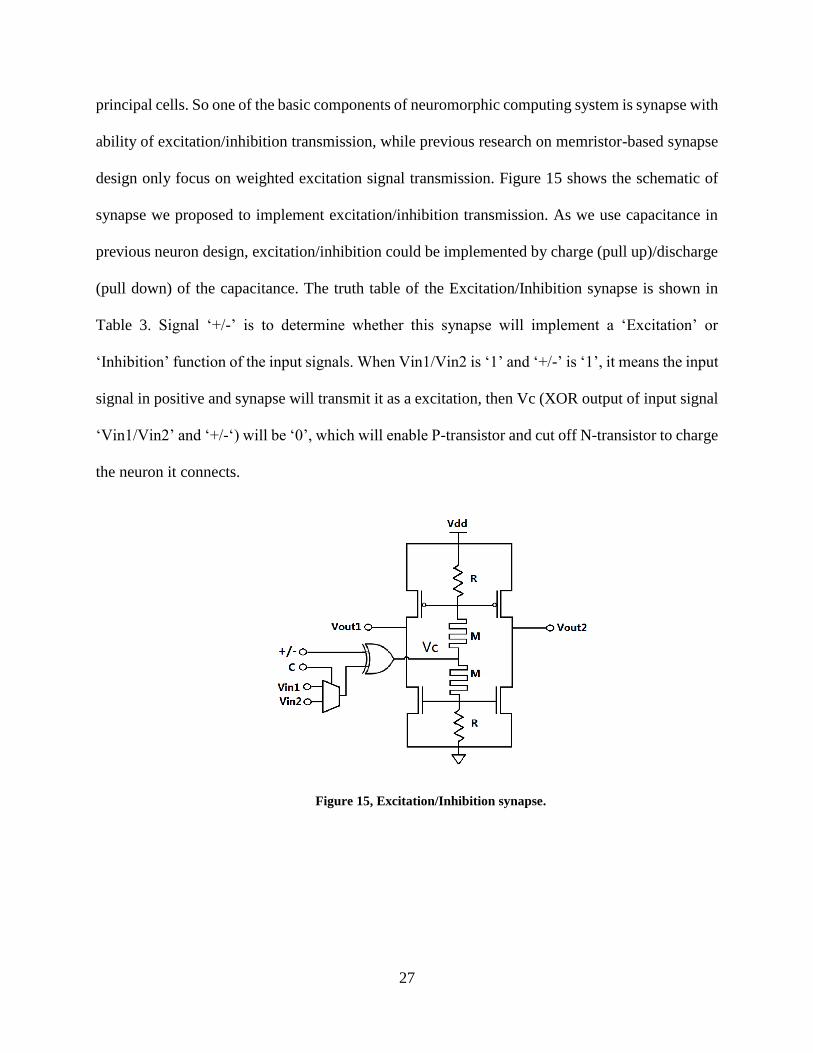
principal cells. So one of the basic components of neuromorphic computing system is synapse with
ability of excitation/inhibition transmission, while previous research on memristor-based synapse
design only focus on weighted excitation signal transmission. Figure 15 shows the schematic of
synapse we proposed to implement excitation/inhibition transmission. As we use capacitance in
previous neuron design, excitation/inhibition could be implemented by charge (pull up)/discharge
(pull down) of the capacitance. The truth table of the Excitation/Inhibition synapse is shown in
Table 3. Signal ‘+/-’ is to determine whether this synapse will implement a ‘Excitation’ or
‘Inhibition’ function of the input signals. When Vin1/Vin2 is ‘1’ and ‘+/-’ is ‘1’, it means the input
signal in positive and synapse will transmit it as a excitation, then Vc (XOR output of input signal
‘Vin1/Vin2’ and ‘+/-‘) will be ‘0’, which will enable P-transistor and cut off N-transistor to charge
the neuron it connects.
Figure 15, Excitation/Inhibition synapse.

28
Table 3, Excitation/Inhibition synapse Truth Table
Vin1/Vin2 +/- P-transistor N-transistor Vout1/Vout2
1 1 Pass Cut off Pull up
1 0 Cut off Pass Pull down
0 1 Cut off Pass Pull down
0 0 Pass Cut off Pull up
To demonstrate the weighted Excitation/Inhibition transmission ability of the synapse we
proposed, a simple information collecting neuron demo (shown in Figure 16) is designed and
simulated in Cadence environment.
Figure 16, Information Collecting Neuron Demo.
In this demo, neuron N0 collects information from other neurons through synapses as we
proposed. Based on the weighted Excitation/Inhibition signals from 30 other neurons, neuron N0
makes decision with a non-linear function:
N0 = { 1 𝑖𝑓 ∑𝑁𝑖 ×𝑊𝑖 ≥ 𝑡ℎ𝑟𝑒𝑠ℎ𝑜𝑙𝑑
30
𝑖=0
0 𝑜𝑡ℎ𝑒𝑟𝑤𝑖𝑠𝑒
(9)

29
We give different set of excitation weight, inhibition weight to every synapse, and test the
state of N0 by increasing the number of positive input neurons. Result is shown as Figure 17.
Figure 17, Simulation of Information Collecting Neuron Demo.
Curves from the left to right are test results with positive/negative synapse weights ratio of
3/1, 2/1, 1/1, 1/2, 1/3, and the positive neurons needed to change the state of N0 is 7, 10, 15, 21,
23 accordingly.

30
6.3 SYNAPSE BASED NEUROMORPHIC COMPUTING SYSTEM
6.3.1 System Architecture
A memristor behaves similarly to a synapse in biological systems and hence can be easily used as
the weighted connections in neural networks. Based on the memristor-based bidirectional synapse
design, we implement a network serving as neuromorphic computing system with units (artificial
neurons) and weighted connections (synapses). The neuron in this network is a binary threshold
unit that produces only two different values to represent its state. A synapse works as a weighted
connection to transmit a signal from one neuron to another. The activation function can be
described in equation (9). The proposed neural network can be used for pattern recognition: first,
multiple standard input images are used to train the connection weights of the system till they reach
convergence; after that, any input pattern will produce to a local minimum, which is a stable state
corresponding to one the stored standard patterns. Such a network system can even be used to
recognize the input image with defects. In our experiment, we build a network with 100 (10×10)
neurons and store the character images ‘A’, ‘B’ and ‘C’ shown in Figure 18(a) as the standard
patterns. Each neuron in the network represents a pixel of the image. Then the defected images
in Figure 18(b) are applied as inputs to initialize the network’s state. Figure 18(c) show that each
input has 13 defects compared to its corresponding standard images (see black bars). The proposed
system can completely eliminate the difference to zero and converge to one of the standard
patterns, as demonstrated by the write bars in Figure 18(c).

31
Figure 18, (a) Standard patterns; (b) Noised patterns; (c) Noised input (black bars) VS output.
6.4 SYSTEM EVALUATGION
6.4.1 Robustness
The maximal allowed stored standard patterns (capacity) of this neural network design is
determined by the amounts of neurons and connections. Moreover, the more patterns stored in the
system, the higher precision of the connection weights is needed. Therefore, a large number of
stored patterns and the high process variation on memristances will result in a higher failure
probability (Pf). To quantitatively evaluate the impact of memristance variations and robustness
of the proposed neural network design, we conducted Monte-Carlo simulations for the network
with 100 (10×10) neurons. Random variations following Gaussian distribution have been injected
to the memristors. And σ is the standard deviation of the memristance. The system could fail to
recognize the noised patterns or mismatch an input with other standard patterns due to the

32
inaccurate connection weights. To test the failure probability under different conditions, we ran
10,000 Monte-Carlo simulations by varying the memristance variation σ when 7, 8, 9, or 10
patterns are stored in the system. In this experiment, each input image contains 21 defects among
100 pixels.
The simulation results in Figure 19 demonstrate that the proposed memristor-based neuromorphic
system has a high tolerance on memristance variations. When σ < 0.4 Pf of all the four
configuration are close to the ideal condition at σ= 0. This indicates that even a large process
variation exists in memristor devices; the performance of the proposed neuromorphic system is
not affected much. Further increasing σ > 0.5, Pf grows significantly. As expected, under the same
process variation condition, the system suffers a higher Pf when more patterns are stored.
Figure 19, The Impact of Memristor Variations on the Probability of Failure (Pf)
6.4.2 Capacity Analysis
For the artificial neural network we implemented last month, the capacitance works as a key factor
to the robustness of the system. It shows that if error in recalling is allowed, the maximum number
p of the patterns to be stored in a network with N neurons is 0.15N [19]. The limitation is attributed

33
to the fact that the network is trapped to the so called spurious local minima. In 1987 McEliece et
al. [9] proved that when p<N/4lnN holds, the Hopfield’s model is able to recall all the memorized
patterns without error.
For demonstration, we conducted Monte-Carlo simulations to evaluate the impacts of the capacity
on the robustness of our networks. A large Hopfield network with 100 neurons is built to recognize
larger sets of text patterns where the respective theoretical capacity is limited to about 18 patterns.
Process variations are simulated by introducing Gaussian distribution noise to the memristance of
the memristor devices in Matlab simulations. A system failure is defined as converging to a wrong
standard pattern (ones that do not correspond to the input pattern), or failing to converge to a stable
point. The test results are shown in Figure 20. Here σ is the standard deviation of the memristance
and Pf is the system failure rate.
Figure 20, Failure Rate of Hopfield Network under Different Patterns and Process Variation.

34
Figure 20 shows that our design has a good immunity against process variations: Even
when σ< 0.2, our system still demonstrates a Pf close to zero. Increasing the number of text
patterns quickly degrades the system’s robustness with much higher Pf values. When the pattern
number approaches the capacity limit, the pace of the system robustness degradation rises quickly.
Increased process variations (σ) were also shown to degrade system robustness. However, in
conventional CMOS circuit manufacturing, the parametric standard deviation is usually less than
10% [16][18].
For the same amount of stored patterns, a larger network with more neurons is more robust
to process variations. Figure 21 compares the performance of the systems with 100 neurons (the
blue line) and with 400 neurons (the green line). Both systems have 10 standard patterns. And the
input defect rate remains at 21% for the two designs. The simulations show that the impact of
process variations is smaller and therefore the required precision of connection weights is lower
in a bigger network. Hence, in a neural network system design, the tradeoff between network
capacity and robustness need to considered.
Figure 21, Increasing the Network Size VS Pf.

35
6.5 COMPARISON BETWEEN CROSSBAR AND SYNAPSE BASED
ARCHITECTURE
Figure 22 shows the synapse-based image smoothing processor. Input neurons matrix (red) stores
the original image, in which each neuron represents the value of a pixel. Each neuron in output
matrix (green) will be calculated by weighted summation of neighbor input neurons:
No(i, j) =1
4(𝑁𝑖(𝑖, 𝑗) + 𝑁𝑖(𝑖 + 1, 𝑗) + 𝑁𝑖(𝑖, 𝑗 + 1) + 𝑁𝑖(𝑖 + 1, 𝑗 + 1)) (10)
Figure 22, Synapse-based Image Smoothing Processor.
The synapse-based architecture is very efficient for this function because it is local
processing, in which there is no connections between long distance neurons. If we implement the
same function with crossbar-based architecture, the weighted matrix will be a sparse matrix that
only has two non-zero elements in each row or column. But for fully connected network, circuit

36
area consumption efficiency of these two architectures depends on system capacity. Crossbar has
peripheral analog circuit that domains the circuit area when system capacity is small while
synapse shows less efficiency for large system. We give a general case estimation in Figure 23,
which shows that for system of more than 320 crossbar-based architecture has better efficiency.
Figure 23, Synapse-based Image Smoothing Processor Area Cost.

37
7.0 CONCLUSION
In this thesis, we proposed a noise-eliminating training method and digital-assisted
initialization step to improve the training process robustness and the performance of memristors
crossbar-based neuromorphic computing engine. Experimental results show that our techniques
can significantly improve the recall success rate and training time of neuromorphic computing
system by up to 18.7%~36.2% and 12.6%~ 14.1%, respectively, through suppressing the noise
accumulation in the training iterations and reducing mismatch between the initial weight matrix
state and the target value.
We also proposed a memristor-based bidirectional transmission exhibition/inhibition
synapse and implemented neuromorphic computing demonstration with our proposed synapse.
Experiment results show that the proposed design has high tolerance on process variation and input
noise.
In the end, memristor crossbar-based and synapse-based neuromorphic computing
architectures are compared and discussed on circuit area consumption efficiency. The synapse-
based architecture is very efficient for this function because it is local processing, while crossbar
shows high efficiency in fully connected network.

38
BIBLIOGRAPHY
[1] Hsin Chen, Sylvain Saighi, Laure Buhry, Sylvie Renaud, “Real-Time Simulation of
Biologically Realistic Stochastic Neurons,” in IEEE Transactions on Neural Networks,
pages 1511-1517, 2010.
[2] Leon Chua., “Memristor-the Missing Circuit Element,” in IEEE Transactions on Circuit
Theory, pages 507-519, 1971.
[3] Miao Hu, Hai Li, Qing Wu and Garrett S. Rose “Hardware realization of BSB Recall
Function Using Memristor Crossbar,” in DAC, pages 498-503, 2012.
[4] Sung Hyun Jo, Ting Chang, Idongesit Ebong, Bhavitavya B. Bhadviya, Pinaki Mazumder
and Wei Lu, “Nanoscale Memristor Device as Synapse in Neuromorphic Systems,” in
Nano Letters, pages 1297-1301, 2010.
[5] Sung Hyun Jo, Ting Chang, Idongesit Ebong, Bhavitavya B. Bhadviya, Pinaki Mazumder,
and Wei Lu., “A Functional Hybrid Memristor Crossbar-Array/CMOS System for Data
Storage and Neuromorphic,” in Nano Letters, pages 389-395, 2012.
[6] Djaafar Chabi and Jacques-Olivier Klein, “Hight fault tolerance in neural crossbar,” in
DTIS, pages 1-6, 2010.
[7] Rakesh Kumar, Dean M. Tullsen and Norman P. Jouppi, “Heterogeneous chip
multiprocessors,” In Computers, pages 32-38, 2005.
[8] Félix Moreno, Jaime Alarcón, Rubén Salvador, and Teresa Riesgo, “Reconfigurable
Hardware Architecture of a Shape Recognition System Based on Specialized Tiny Neural
Networks With Online Training,” in IEEE Transactions on Industrial Electronics, page
3253-3263, 2009.
[9] Shimeng Yu and H.-S. Philip Wong, “Modeling the Switching Dynamics of
Programmable-Metallization-Cell (PMC) Memory and its Application as Synapse Device
for a Neuro-morphic Computation System” In APL, page 103514-3, 2011.
[10] Theodore Yu, and Gert Cauwenberghs, “Analog VLSI Biophysical Neurons and Synapses
With Programmable Membrane Channel Kinetics,” In IEEE Transactions on Biomedical
Circuits and Systems, page 139-148, 2010.
[11] Zhuo Feng and Peng Li, “Multigrid on GPU: Tackling Power Grid Analysis on parallel
SIMT platforms” International Conference on Computer-Aided Design (ICCAD), pages
647-654, 2008.

39
[12] Dmitri B. Strukov, Gregory S. Snider, Duncan R. Stewart, R. Stanley Williams, “The
missing memristor found,” Nature, vol. 453, pp. 80-83, 2008.
[13] X. Wang, Yiran Chen, haiwen Xi, Hai Li, Dimitrov, D., “Spintronic memristor through
spin-torque-induced magnetization motion,” IEEE Electron Device Letters, vol. 30, pp.
294-297, 2009.
[14] Yenpo Ho, Huang, G.M. Peng L, “Nonvolatile memristor memory: device characteristics
and design implications,” in Proceedings of the 2009 International Conference on
Computer-Aided Design. ACM, 2009, pp. 485–490.
[15] Diming Niu, Yiran Chen, Cong Xu, and Yuan Xie, “Impact of process variations on
emerging memristor,” in Design Automation Conference (DAC), 2010, pp. 877–882.
[16] McEliece, R.J., Posner, Edward C., Rodemich, Eugene R., Venkatesh, S.S., “The capacity
of the Hopfield Associative Memory.” IEEE Trans. Information Theory IT-33. pp461-482,
1987.
[17] J. Liang and P.Wong, “Cross-Point Memory Array without Cell Selectors Device
Characteristics and Data Storage Pattern Dependencies,” In IEEE Trans. on Electron
Devices, pages 2531–2538, 2010.
[18] J. Partzsch and R. Schuffny, “Analyzing the scaling of connectivity in neuromorphic
hardware and in models of neural networks,” Neural Networks, IEEE Transactions on, vol.
22, no. 6, pp. 919–935, 2011.
[19] M. Wang, B. Yan, J. Hu, and P. Li, “Simulation of large neuronal networks with
biophysically accurate models on graphics processors,” in Neural Networks (IJCNN), The
2011 International Joint Conference on. IEEE, 2011, pp. 3184–3193.
[20] H. Shayani, P. Bentley, and A. Tyrrell, “Hardware implementation of a bioplausible neuron
model for evolution and growth of spiking neural networks on fpga,” in NASA/ESA
Conference on Adaptive Hardware and Systems. IEEE, 2008, pp. 236–243.