merve tÜrkġanli - bilkent university · fotodinamik terapi, fotouyarıcının belirli bir ......
TRANSCRIPT
COVALENTLY FUNCTIONALIZED MSNS AS POTENTIAL
PHOTOSENSITIZING AGENTS FOR PDT
A THESIS
SUBMITTED TO THE MATERIALS SCIENCE AND NANOTECHNOLOGY
PROGRAM OF THE INSTITUTE OF ENGINEERING AND SCIENCES
OF BĠLKENT UNIVERSITY
IN PARTIAL FULFILLMENT OF THE REQUIREMENTS
FOR THE DEGREE OF
MASTER OF SCIENCE
By
MERVE TÜRKġANLI
January 2011

ii
I certify that I have read this thesis and that in my opinion it is fully adequate, in
scope and in quality, as a thesis of the degree of Master of Science.
………………………………….
Prof. Dr. Engin U. Akkaya (Principal Advisor)
I certify that I have read this thesis and that in my opinion it is fully adequate, in
scope and in quality, as a thesis of the degree of Master of Science.
………………………………….
Assist. Prof. Dr. Mehmet Bayındır
I certify that I have read this thesis and that in my opinion it is fully adequate, in
scope and in quality, as a thesis of the degree of Master of Science.
………………………………….
Prof. Dr. Özdemir Doğan
Approved for the Institute of Engineering and Science:
………………………………….
Prof. Dr. Levent Onural
Director of the Institute of Engineering and Science

iii
ABSTRACT
COVALENTLY FUNCTIONALIZED MSNS AS POTENTIAL
PHOTOSENSITIZING AGENTS FOR PDT
Merve TürkĢanlı
M.S. in Materials Science and Nanotechnology
Supervisor: Prof. Dr. Engin U. Akkaya
January, 2011
Photodynamic therapy (PDT) is a novel approach for the treatment of some cancers
and other non-malignant diseases. PDT aims to kill cancer tissue by the generation
of singlet oxygen as a result of excitation of the photosensitizer (PS) by illuminating
with a light source at a certain wavelength. Mesoporous silica nanoparticles are
promising in PDT issue due to their chemical inertness, biocompatibility, low-
toxicity, hydrophility and ease of surface modification. We have synthesized and
characterized novel boradiazaindacene (BODIPY)-based PS that is covalently
attached to the pore of mesoporous silica nanoparticles (MSNs). We have observed
that near infrared absorbing photosensitizer attached MSNs successfully generate
cytotoxic singlet oxygen.
Keywords: Boradiazaindacene, photodynamic therapy, photosensitizer, mesoporous
silica nanoparticles, drug carrier system.
iv
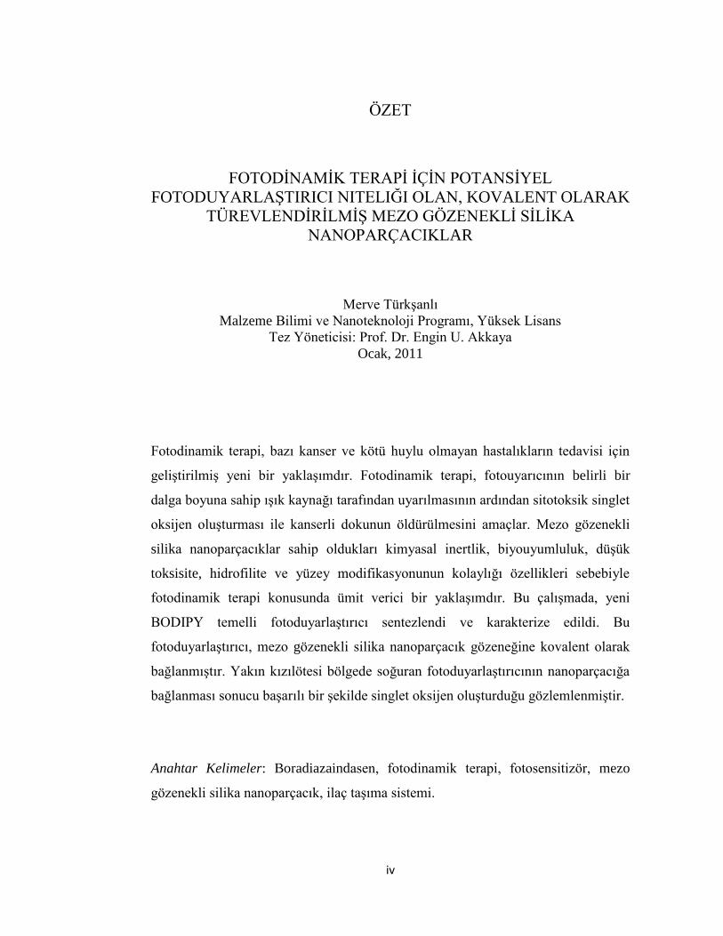
ÖZET
FOTODĠNAMĠK TERAPĠ ĠÇĠN POTANSĠYEL
FOTODUYARLAġTIRICI NITELIĞI OLAN, KOVALENT OLARAK
TÜREVLENDĠRĠLMĠġ MEZO GÖZENEKLĠ SĠLĠKA
NANOPARÇACIKLAR
Merve TürkĢanlı
Malzeme Bilimi ve Nanoteknoloji Programı, Yüksek Lisans
Tez Yöneticisi: Prof. Dr. Engin U. Akkaya
Ocak, 2011
Fotodinamik terapi, bazı kanser ve kötü huylu olmayan hastalıkların tedavisi için
geliĢtirilmiĢ yeni bir yaklaĢımdır. Fotodinamik terapi, fotouyarıcının belirli bir
dalga boyuna sahip ıĢık kaynağı tarafından uyarılmasının ardından sitotoksik singlet
oksijen oluĢturması ile kanserli dokunun öldürülmesini amaçlar. Mezo gözenekli
silika nanoparçacıklar sahip oldukları kimyasal inertlik, biyouyumluluk, düĢük
toksisite, hidrofilite ve yüzey modifikasyonunun kolaylığı özellikleri sebebiyle
fotodinamik terapi konusunda ümit verici bir yaklaĢımdır. Bu çalıĢmada, yeni
BODIPY temelli fotoduyarlaĢtırıcı sentezlendi ve karakterize edildi. Bu
fotoduyarlaĢtırıcı, mezo gözenekli silika nanoparçacık gözeneğine kovalent olarak
bağlanmıĢtır. Yakın kızılötesi bölgede soğuran fotoduyarlaĢtırıcının nanoparçacığa
bağlanması sonucu baĢarılı bir Ģekilde singlet oksijen oluĢturduğu gözlemlenmiĢtir.
Anahtar Kelimeler: Boradiazaindasen, fotodinamik terapi, fotosensitizör, mezo
gözenekli silika nanoparçacık, ilaç taĢıma sistemi.

v
Dedicated to my husband
vi
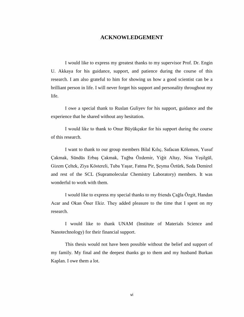
ACKNOWLEDGEMENT
I would like to express my greatest thanks to my supervisor Prof. Dr. Engin
U. Akkaya for his guidance, support, and patience during the course of this
research. I am also grateful to him for showing us how a good scientist can be a
brilliant person in life. I will never forget his support and personality throughout my
life.
I owe a special thank to Ruslan Guliyev for his support, guidance and the
experience that he shared without any hesitation.
I would like to thank to Onur Büyükçakır for his support during the course
of this research.
I want to thank to our group members Bilal Kılıç, Safacan Kölemen, Yusuf
Çakmak, Sündüs ErbaĢ Çakmak, Tuğba Özdemir, Yiğit Altay, Nisa YeĢilgül,
Gizem Çeltek, Ziya Köstereli, Tuba YaĢar, Fatma Pir, ġeyma Öztürk, Seda Demirel
and rest of the SCL (Supramolecular Chemistry Laboratory) members. It was
wonderful to work with them.
I would like to express my special thanks to my friends Çağla Özgit, Handan
Acar and Okan Öner Ekiz. They added pleasure to the time that I spent on my
research.
I would like to thank UNAM (Institute of Materials Science and
Nanotechnology) for their financial support.
This thesis would not have been possible without the belief and support of
my family. My final and the deepest thanks go to them and my husband Burkan
Kaplan. I owe them a lot.

vii
LIST OF ABBREVIATIONS
PDT: Photodynamic Therapy
PS: Photosensitizer
MSN: Mesoporous Silica Nanoparticle
PS-MSN: Photosensitizer attached mesoporous silica nanoparticle
FDA: Food and Drug Administration
THF: Tetrahydrofuran
TFA: Trifluoroacetic Acid
DPBF: 1, 3 Diphenylisobenzofuran
TEM: Transmission Electron Microscopy
SEM: Scanning Electron Microscopy
XRD: X-ray Diffraction
NMR: Nuclear Magnetic Resonance
BODIPY: Boradiazaindacene
.
viii
TABLE OF CONTENTS
INTRODUCTION ............................................................................................. 1
1.1Photodynamic Therapy .................................................................................. 1
1.1.1 History of Photodynamic Therapy ...................................................... 2
1.1.2. Working Mechanism of Photodynamic Therapy ............................... 3
1.1.3. Photosensitizing Agents ..................................................................... 5
1.1.3.1 Clinical Studies of Photosensitizing Agents ........................... 6
1.1.3.2 Boron dipyrromethene (BODIPY) dyes ............................... 10
1.1.4. Light Sources ................................................................................... 13
1.2 Requirements for Drug Delivery Systems .................................................. 13
1.2.1 Nanoparticles as photosensitizer carriers for PDT ............................ 14
1.3. Mesoporous silica nanoparticles (MSNs) as PS carrier ............................. 15
EXPERIMENTAL PROCEDURES .............................................................. 17
2.1 General ........................................................................................................ 17
2.2 Synthesis of Photosensitizer ........................................................................ 19
2.2.1 Synthesis of 4-(3-bromopropoxy)benzaldehyde (3) ......................... 19
2.2.2 Synthesis of 4-(3-azidopropoxy)benzaldeyhde (4) .......................... 20
ix
2.2.3 Synthesis of 8-(4-(6-azidohexyloxy)phenyl)-1,3,5,7-tetramethyl-
BODIPY (5) ............................................................................................... 21
2.2.4 Synthesis of 8-(4-(6-azidohexyloxy)phenyl)-2,6-dibromo1,3,5,7-
tetramethyl-BODIPY (6) ............................................................................ 22
2.2.5 Synthesis of Compound 7 ................................................................ 24
2.2.6 Synthesis of 3-isothiocyanatoprop-1-yne (8) .................................... 25
2.2.7 Synthesis of Compound 9 (Click Reaction) ...................................... 26
2.2.8 Synthesis of MSNs ............................................................................ 27
2.2.9. Synthesis of PS-MSNs ..................................................................... 28
RESULTS AND DISCUSSION ...................................................................... 29
3.1 MSNs as a Carrier System for Photosensitizer ........................................... 29
3.1.1 Design of Photosensitizer .................................................................. 29
3.1.2 Design of MSNs ................................................................................ 31
CONCLUSION ................................................................................................ 41
REFERENCES ................................................................................................ 42
APPENDİX A .................................................................................................. 46
APPENDİX B ................................................................................................... 58

x
LIST OF FIGURES
Figure 1. The principle of Photodynamic Therapy………………………………. 16
Figure 2. The optical absorption of various tissue components and therapautic
window of body .......................................................................................................... 6
Figure 3. Structures of some photosensitizers in literature. ...................................... 9
Figure 4. One-pot synthesis of different styryl BODIP dyes35. ............................ 10
Figure 5. Absorption and emission spectra of styryl BODIPY dyes35. .................. 11
Figure 6. BODIPY- based photosensitizers in literature. Compound 1 is the first
BODIPY-based photosensitizrs reported by Nagano et al., compound 2 and 3 were
reported by Akkaya et al.35, 36, 34 ......................................................................... 11
Figure 7. Smart photosensitizer that is selective to tumor tissue environment34. .. 12
Figure 8. Synthesis pathway of MCM-4146 . ......................................................... 16
Figure 9. Synthesis of compound 3 ......................................................................... 19
Figure 10. Synthesis of compound 4 ....................................................................... 20
Figure 11. Synthesis of compound 5 ....................................................................... 21
Figure 12. Synthesis of compound 6 ....................................................................... 22
Figure 13. Synthesis of compound 7 ....................................................................... 24
Figure 14. Synthesis of compound 8 ....................................................................... 25
xi
Figure 15. Synthesis of compound 9 ....................................................................... 26
Figure 16. Schematic drawing of PS-MSNs ............................................................ 28
Figure 17. The absorbance of compoun 9 in CHCl3……………………………...42
Figure 18. Fluorescense emission of compound 9 in CHCl3. Excitation is at 650
nm. ............................................................................................................................ 31
Figure 19. SEM images of MSNs ............................................................................ 32
Figure 20. TEM images of MSNs ........................................................................... 33
Figure 21. X-ray diffractogram of MSN. ............................................................... 34
Figure 22. Size distribution of MSNs in water. ....................................................... 35
Figure 23. Zeta potential distribution of MSNs ....................................................... 36
Figure 24. Nitrogen isotherm for all silica MCM-41. ............................................. 37
Figure 25. Absorbance of DPBF in isopropanol. Each measurement was done after
30 seconds of illumination. ...................................................................................... 38
Figure 26. Absorbance spectra of PS-MSNs in isopropanol. Each measurement
was done after 30 seconds of illumination. ............................................................. 39
Figure 27. Bleaching of DPBF in the presence of PS-MSNs. ................................. 40
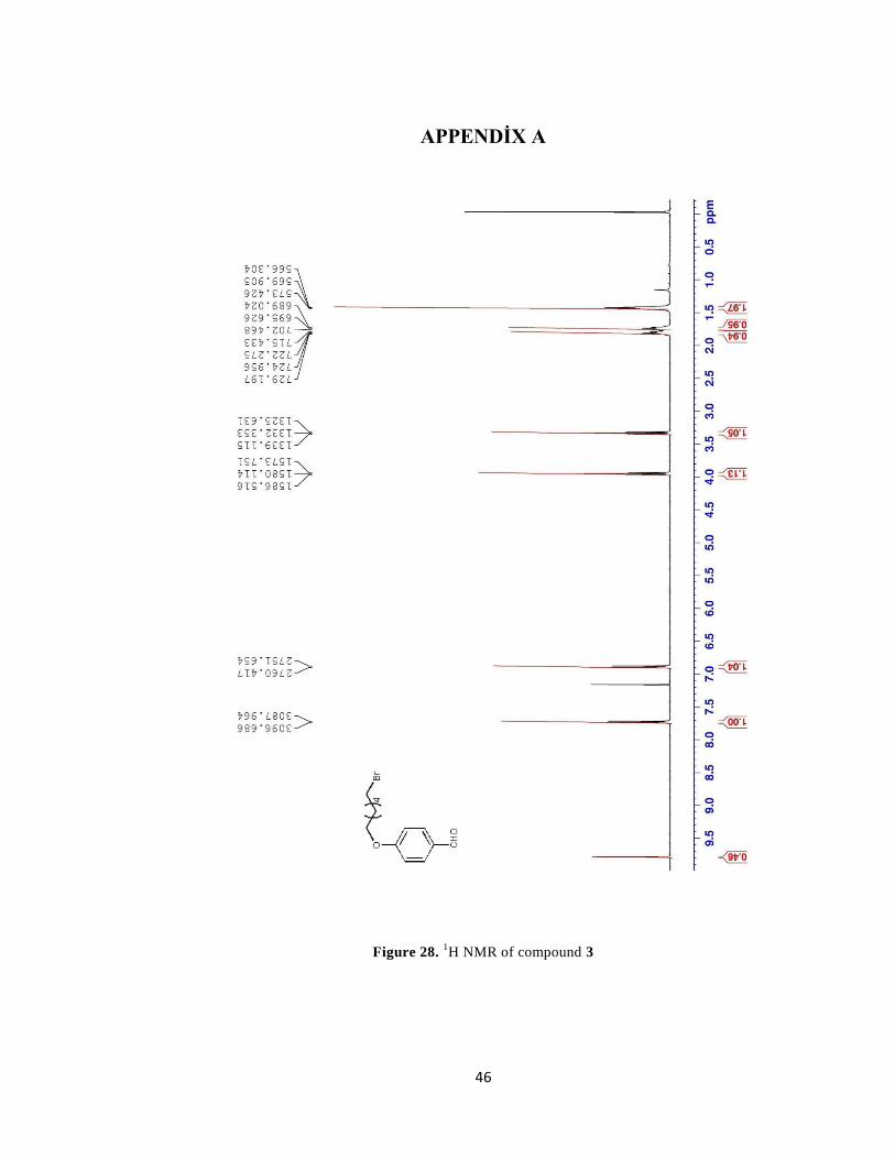
Figure 28. 1H NMR of compound 3 ....................................................................... 46
Figure 29. 1H NMR of compound 4 ....................................................................... 47
Figure 30. 1H NMR of compound 5 ....................................................................... 48
Figure 31. 1H NMR of compound 6 ....................................................................... 49
Figure 32. 1H NMR of compound 7 ....................................................................... 50
Figure 33. 1H NMR of compound 9 ....................................................................... 51
xii
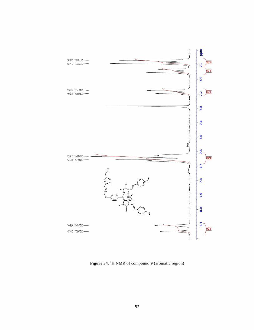
Figure 34. 1H NMR of compound 9 (aromatic region) ........................................... 52
Figure 35. 13C NMR of compound 5 ..................................................................... 53
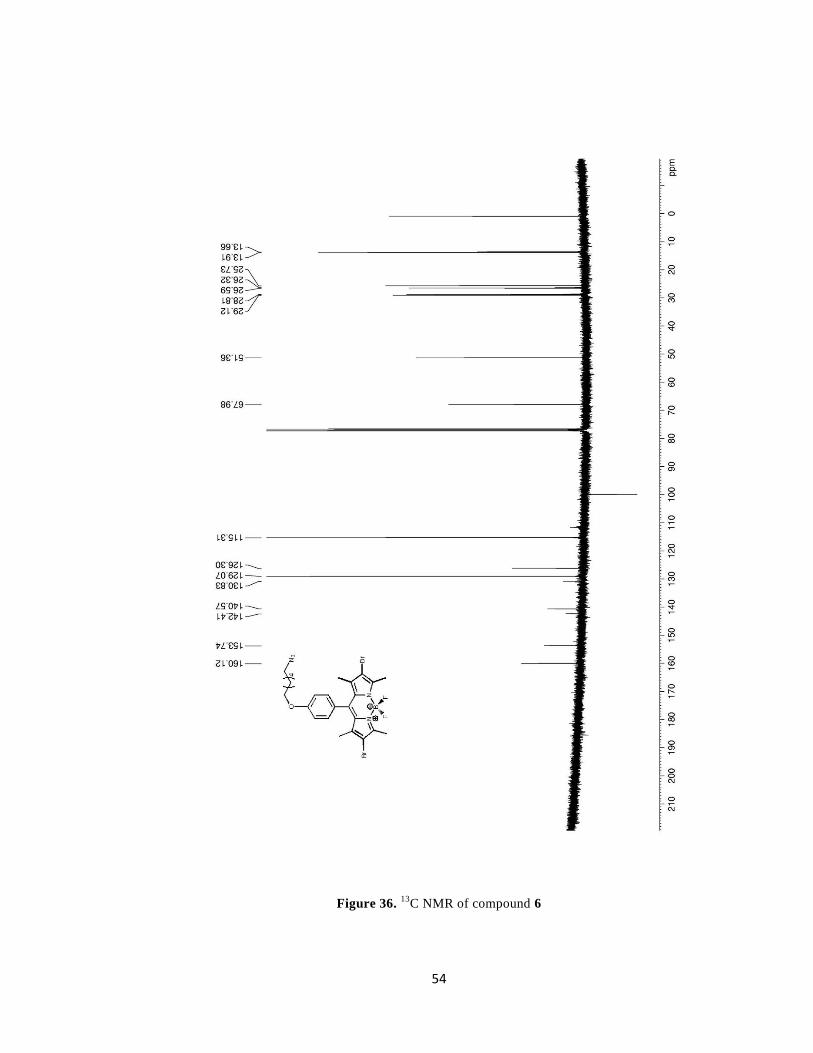
Figure 36. 13C NMR of compound 6 ...................................................................... 54
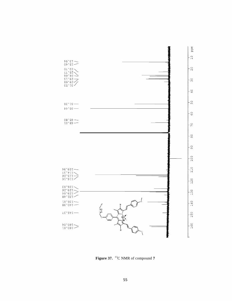
Figure 37. 13C NMR of compound 7 ..................................................................... 55
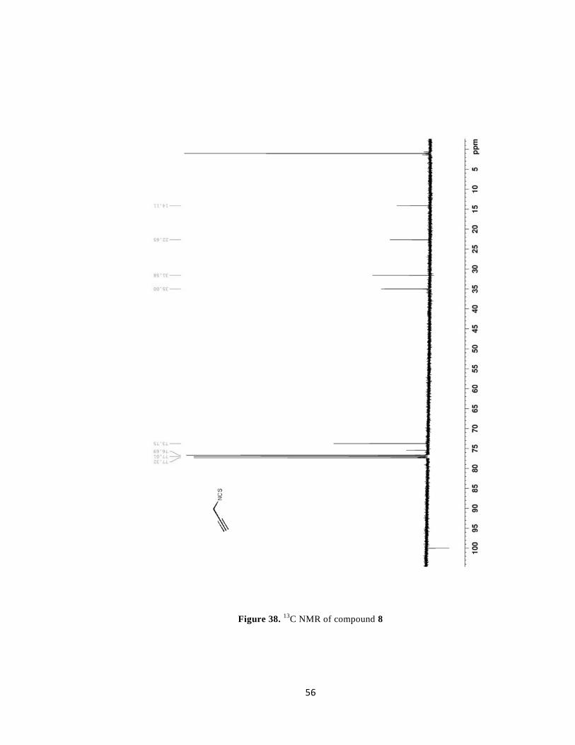
Figure 38. 13C NMR of compound 8 ...................................................................... 56
Figure 40. ESI-HRMS of compound 5 ................................................................... 58
Figure 41. ESI-HRMS of compound 6 .................................................................... 58
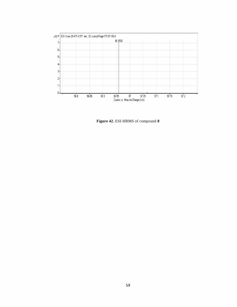
Figure 42. ESI-HRMS of compound 8 .................................................................... 59
Figur 43. MALDI-MS of compound 9 .................................................................... 60

1
CHAPTER 1
INTRODUCTION
1.1 Photodynamic Therapy
Photodynamic therapy is a novel, promising approach for the treatment of some
cancers and other non-malignant diseases. The therapy involves two important
stages; administration of a photosensitizer and illumination of the tissue to activate
the photosensitizer with the light of a specific wavelength. When the tissue is
illuminated, the photosensitizer which previously localized at the tumor is excited.
The excitation of the molecule leads to several molecular energy transfers and
finally highly reactive and cytotoxic oxygen species called singlet oxygen (1O2) is
produced 1. In biological systems,
1O2 has a lifetime of <0,04 microsecond
2. During
this very short interval, 1O2 species causes cancer cells damaged or destroyed either
targeting the cells directly, causing necrosis and/or apoptosis3
or by targeting
tumour or healthy surrounding vasculature 4.
PDT has numerous advantages over the traditional treatment methods of cancer
such as surgery, radiotherapy and chemotherapy. Firstly, targeting is achieved by
the delivery of the light. At a certain time after the administration of the drug, light
is targeted into the tumour and surrounding vasculatory by fiber optic systems and
endoscopy. This in turn, causes only damage of tumours. Since the life time of 1O2
2
species is very short, it migrates less than 0.02 µm after its generation5
. As a result
it is deactivated before it can flee out of the cell.
Secondly, the tumours have abnormal physiology such as; leaks at vasculatory,
lower pH value, higher number of low density protein receptors, presence of
macrophages, larger amount of lipids2. The photosensitizers which are developed
for these environments achieve selectivity. On the other hand, limitation of PDT
rises because of the fact that it cannot treat the advanced disseminated diseases
since the illumination of the entire body and the uptaken of the appropriate doses of
drug is impossible.
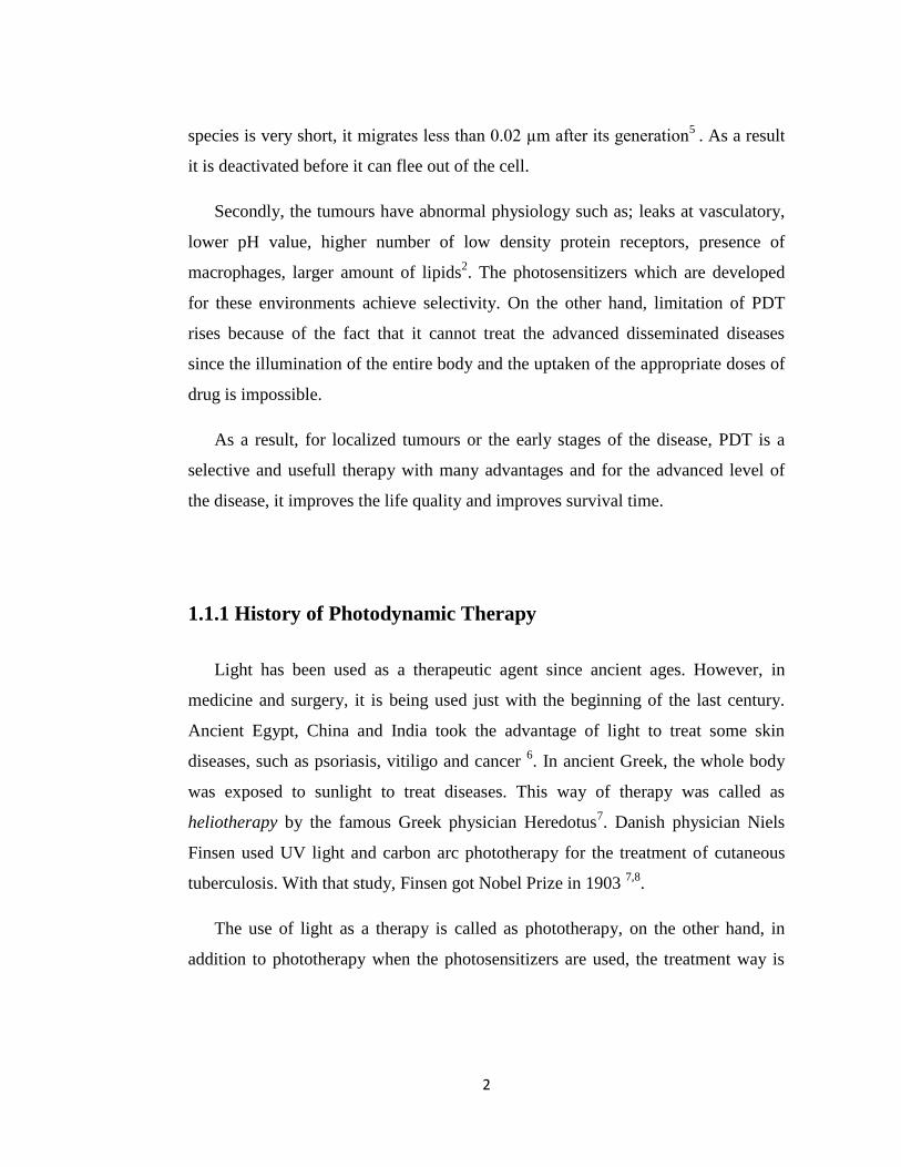
As a result, for localized tumours or the early stages of the disease, PDT is a
selective and usefull therapy with many advantages and for the advanced level of
the disease, it improves the life quality and improves survival time.
1.1.1 History of Photodynamic Therapy
Light has been used as a therapeutic agent since ancient ages. However, in
medicine and surgery, it is being used just with the beginning of the last century.
Ancient Egypt, China and India took the advantage of light to treat some skin
diseases, such as psoriasis, vitiligo and cancer 6. In ancient Greek, the whole body
was exposed to sunlight to treat diseases. This way of therapy was called as
heliotherapy by the famous Greek physician Heredotus7. Danish physician Niels
Finsen used UV light and carbon arc phototherapy for the treatment of cutaneous
tuberculosis. With that study, Finsen got Nobel Prize in 1903 7,8
.
The use of light as a therapy is called as phototherapy, on the other hand, in
addition to phototherapy when the photosensitizers are used, the treatment way is

3
called photochemotherapy. Photochemotherapy also has a history of 3000 years.
Indians first employed psoralens with light to treat vitiligo 9.
Photodynamic therapy, acquiring cell death by the use of photosensitizer with a
light, has been familiar for 100 years. First medical application of photodynamic
therapy in literature was done by von Tappeiner and a dermatologist named
Jesionek. They used topical eosin and white light for the treatment of skin cancer10
.
The requirement of oxygen in the reaction environment for the therapy was firstly
introduced by Jodlbauer and von Tappeiner in 1907 and they entitled this
phenomenon as “photodynamic action”11
.
In 1911, Hausmann reported the effect of hematoporphyrin and light on a
paramecium and red blood cells of a mice12
. Friedrich Meyer-Betz injected himself
hematoporphyrin and exposed himself to light in order to observe the effects on
humans as well as mice and he noticed long term pain at the areas where light has
been exposed13
. In 1978, with a 25 skin cancer patients were treated with PDT by
Dougherty and this was the first clinical study which proved PDT can be used for
the treatment of some malignant cancers more successfully than the conventional
therapies14
.
Over the years PDT has been used successfully for the treatment of some other
types of tumor such as, bladder cancer15
, brain tumors16
, head and neck tumors17
,
rectal cancer18
, gynecological tumors19
.
1.1.2. Working Mechanism of Photodynamic Therapy
The activation of the photosensitizer with an appropriate wavelength of a light
initiates the series of energy transfers. When the photosensitizer absorbs the light, it
transfers from ground singlet state (1PS) into its excited singlet state (
1PS*).
1PS*
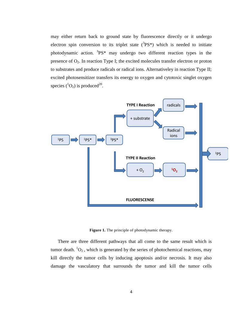
4
may either return back to ground state by fluorescence directly or it undergo
electron spin conversion to its triplet state (3PS*) which is needed to initiate
photodynamic action. 3PS* may undergo two different reaction types in the
presence of O2. In reaction Type I; the excited molecules transfer electron or proton
to substrates and produce radicals or radical ions. Alternativeley in reaction Type II;
excited photosensitizer transfers its energy to oxygen and cytotoxic singlet oxygen
species (1O2) is produced
20.
1PS 1PS*
1O2
Radical ions
radicals
+ O2
+ substrate
1PS
3PS*
TYPE I Reaction
TYPE II Reaction
FLUORESCENSE
Figure 1. The principle of photodynamic therapy.
There are three different pathways that all come to the same result which is
tumor death. 1O2 , which is generated by the series of photochemical reactions, may
kill directly the tumor cells by inducing apoptosis and/or necrosis. It may also
damage the vasculatory that surrounds the tumor and kill the tumor cells
5
indirectly21
. In addition, after PDT treatment, the immune system is induced22
. As a
result, the immune response is initiated to kill the remaining tumor cells.
The vascular response, to kill the surrounding vasculatory of the tumor and
making the tumor starving of oxygen and nutrients23
, is important however,
researchers pay attention more to the effects of PDT in cellular level. The target
sites of the cellular level include mitochondria, the plasma membrane, nuclei and
lyzozomes24
. The effectiveness of PDT is mainly resulted from the apoptotic
response in cells. Apoptosis is programmed cell death due to the change of the
biochemical environment of the cell. The mitochondrial damage is of top priority
which leads to apoptosis 21, 25
.
1.1.3. Photosensitizing Agents
The most ideal photosensitizing agents would have the properties such as,
biostability, photochemically efficient (having a strong absorption peak at
wavelengths >630nm), selective to target tissue (retain at the target tissue relatively
more than normal surrounding tissues), minimum toxicity at the healthy parts of the
body.
Photobleaching, destruction of the fluorescent molecules due to the generation
of singlet oxygen species during the photodynamic action, is one of the main
problems of photosensitizers26
. As a result, photosensitizers must be
photochemically stable.
Light penetration depth of the human tissue limits in the range of 620-850 nm
because of the absorption properties of the medium27
(Fig.2). This limited light
penetration range is called as therapeutic window of the body. The photosenstizers
must have a strong absorption in the region of the therapeutic window, thus they

6
can transfer their energy to oxygen in order to produce cytotoxic singlet oxygen
species28
.
1.1.3.1 Clinical Studies of Photosensitizing Agents
Photofrin (porfimer sodium, Axcan Pharma, Montreal, Canada), a complex
mixture of hematoporphyrin derivatives, is the first drug that was approved for
PDT7. Since photofrin is very effective in terms of; killing the tumor, non-toxic
when there is no illumination and water soluble, it is the most common
photosensitizer for the treatment of some tumors other than dermatological. The
cancers that are treated with photofrin are, early stage lung cancers, cervical cancer,
bladder cancer, gastric cancer and oesophageal adenocarcinoma28
.
Figure 2. The optical absorption of various tissue components and therapautic window of
body.

7
Although porfimer sodium is effective, it has several disadvantages which are
improved in subsequent photosensitizers. The selectivity of the drug between
tumors and healthy tissues is low29
. After the administration of the porfimer sodium
there should be waiting period of 48-72h before the illumination and since the drug
causes skin photosensitivity during this period of time patient must be protected
from light30
.
Research has been done to develop new photosensitizers which have improved
properties over photofrin. Table 1 shows the approved photosensitizers and type of
cancer they are applied.
Table 1. Type of cancer and approved drug20
TYPE OF CANCER PHOTOSENSITIZER COUNTRY
Actinic keratosis ALA (Levulan, Metvix) U.S., EU
Basal Cell Carcinoma ALA (Metvix) EU
Barrett’s HGD Porfimer sodium U.S., Canada, EU, UK
Cervical Cancer Porfimer sodium Japan
Endobronchial Cancer Porfimer sodium Canada, UK,US,EU
Esophageal Cancer Porfimer sodium Canada, UK,US,EU
Gastric Cancer Porfimer sodium Japan
Head and Neck Cancer Foscan EU, Norway, Iceland
Papillary bladder Cancer Porfimer sodium Canada
Abbreviations: ALA, 5-aminolevulinic acid, HGD, high-grade dysplasia

8
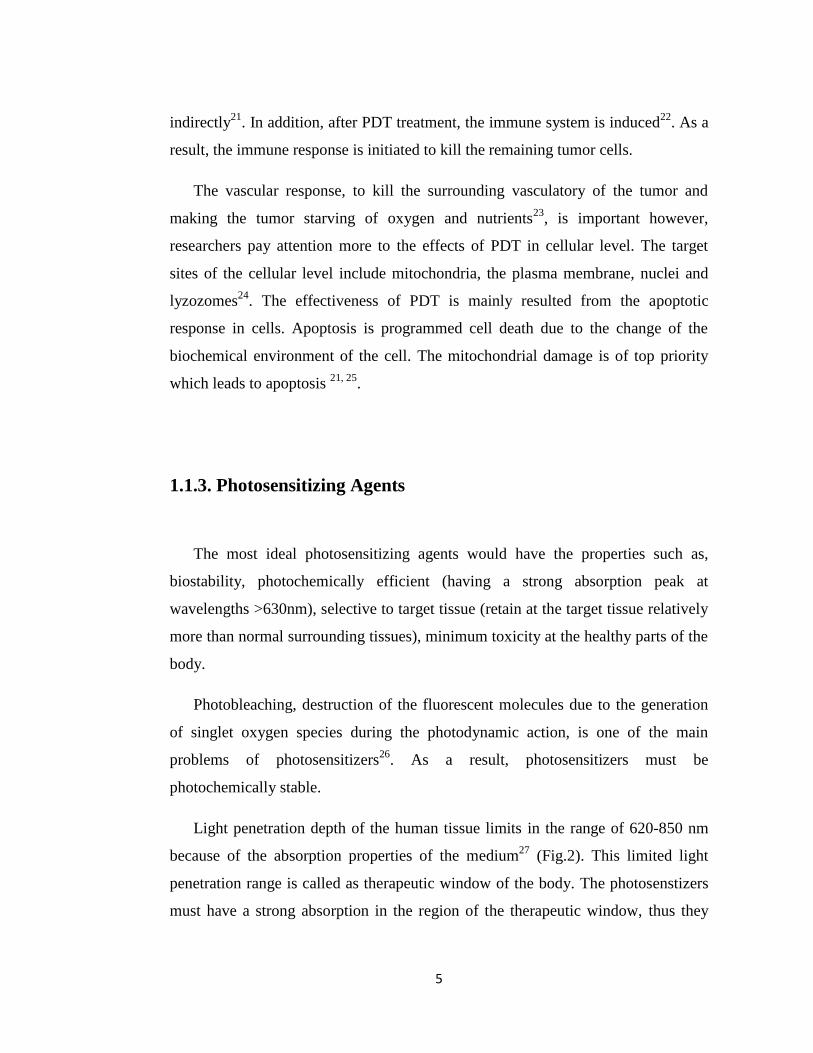
The generality of photosensitizers in literature are hematoporphyrin derivatives.
The structures of some photosensitizers in literature and their absorption
wavelengths within the therapeutic window are given below (see Figure 2.)
Porphyrin derivatives
Phthalocyanines and naphtalocyanines
Hematoporphyrin
(Photofrin), 630nm
Phatalocyanine, 700nm Naphthalocyanine, 780nm
9
Texapyrins Chlorins and Bacteriochlorins
Aza dipyrromethene dyes
Perylenediimide dyes Boron dipyrromethene dyes
Figure 3. Structures of some photosensitizers in literature.
m-THPC,(Foscan), 650nm Texaphyrinato-Lu(III), 600-
900nm
Aza dipyrromethene dyes,
650nm
10
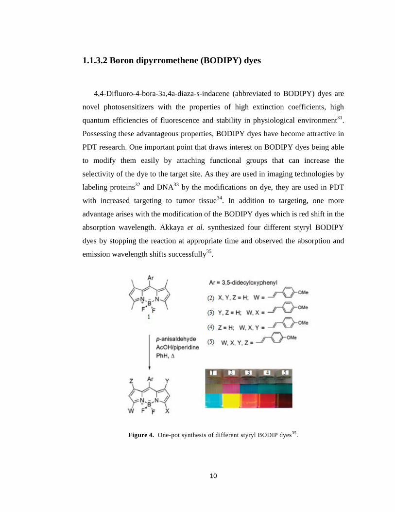
1.1.3.2 Boron dipyrromethene (BODIPY) dyes
4,4-Difluoro-4-bora-3a,4a-diaza-s-indacene (abbreviated to BODIPY) dyes are
novel photosensitizers with the properties of high extinction coefficients, high
quantum efficiencies of fluorescence and stability in physiological environment31
.
Possessing these advantageous properties, BODIPY dyes have become attractive in
PDT research. One important point that draws interest on BODIPY dyes being able
to modify them easily by attaching functional groups that can increase the
selectivity of the dye to the target site. As they are used in imaging technologies by
labeling proteins32
and DNA33
by the modifications on dye, they are used in PDT
with increased targeting to tumor tissue34
. In addition to targeting, one more
advantage arises with the modification of the BODIPY dyes which is red shift in the
absorption wavelength. Akkaya et al. synthesized four different styryl BODIPY
dyes by stopping the reaction at appropriate time and observed the absorption and
emission wavelength shifts successfully35
.
Figure 4. One-pot synthesis of different styryl BODIP dyes35
.
11
Figure 5. Absorption and emission spectra of styryl BODIPY dyes35
.
Figure 6. BODIPY- based photosensitizers in literature. Compound 1 is the first BODIPY-
based photosensitizrs reported by Nagano et al., compound 2 and 3 were reported by Akkaya et
al.35, 36, 34
The study of Akkaya et al.34
is an important example of the modification of
BODIPY for the tumor tissue environment. As it is previously discussed, tumor
12
tissues have abnormal physiological properties such as low pH, high concentration
of Na+ ion. The photosensitizer that was synthesized by Akkaya et al. (compound 3
in fig. 6) has two different functional groups which are sensitive to acidicity and
sodium ion concentration. In the acidic medium, pyridine groups are protonated and
red shift occurs from 630 nm to 660 nm. Thus, only the protonated molecules
would absorb light at 660 nm. In the absence of sodium ion, photo induced electron
transfer (PET) occurs however when the sodium ion concentration increases,
sodium ion binds to crown ether group of the molecule and PET is blocked. By this
way, only in the tumor tissues where the two parameters are above a threshold
value, the 1O2 species would be generated. (Fig. 7)
Figure 7. Smart photosensitizer that is selective to tumor tissue environment34
.
13
1.1.4. Light Sources
For the activation of photosensitizers, conventional arc lamps can be used. They
are cheap and easy to use, however they are broad spectrum light sources so filters
should be used to cut off UV and IR emission to avoid heating. In addition, while
coupling them to light delivery fibers, there occurs optical power loss. Thus, it is
not efficient to use arc lamps clinically.
The development of lasers is an important breakthrough in PDT because early
lasers were expensive, large and cannot removable and expertise is needed to use
them. The development in semiconductor lasers results in cheaper, mobile systems
that can be used corporately with optical fiber technology. For PDT to be
successful, the light should be delivered from source to target homogenously, thus
the optical fibers provide the needs for illumination at different localization.
Light emitting diodes (LEDs) can also be used clinically. They are small,
cheaper than the other light sources and provide a power output up to 150mW/cm2
at wavelengths between 350-1100 nm37
.
1.2 Requirements for Drug Delivery Systems
Over the last decades, many organic dyes, porphyrin derivatives and other
biomolecules have been synthesized as photosensitizing agents. However,
developments in photosensitizing agents yet could not solve all the problems for the
clinical applications.

14
First of all, most of the photosensitizing agents are hydrophobic so they are
water insoluble molecules. Thus, in aqueous media they aggregate easily which in
turn results in two important issues, decrease in quantum efficiency and severity at
injection through the body.
Secondly, to prevent the damage of healthy tissues selective accumulation of
photosensitizing agent is required. Although, recently photosensitizers are
synthesized in order to increase selective targeting, they are still not selective
enough to be applied clinically.
As a result, the construction of stable and effective photosensitive agent carriers
become vital and play an important role for the development of PDT. The common
examples of delivery agents are liposomes, oil dispersions, low-density lipoproteins
and nanoparticles38,39
.
1.2.1 Nanoparticles as photosensitizer carriers for PDT
Recently, nanotechnology focuses on development of nanoparticles as
photosensitizer carriers. Nanomaterials are promising in PDT issue because (1) they
could be made water soluble, i.e. hydrophilic, (2) they have large surface areas
which can be modified with functional groups, thus gain selectivity for the tumor
tissue, (3) they have sub-cellular size so they can easily penetrate deeper into the
tissue and are efficiently taken up by the cell.
PS agent could be encapsulated within their matrix, adsorbed on the material or
conjugated on the surface. Since the surface of these nanoparticles is ready for
modification, tumor seeking sites can be attached to the surface of them which
provides specific targeting. In addition, attachment of a different fluorescent
molecule provides biological imaging of the system.
15
There are various types of nanomaterials that can be used as PS carrier systems,
organic compounds, inorganic oxides, metal compounds.
1.3. Mesoporous silica nanoparticles (MSNs) as PS carrier
Research on ceramic based nanomaterials as a drug carrier system for PDT has
been done recently. Synthesis of organically modified silica nanoparticles
(ORMOSIL) was first reported by Ohulchanskyy et al. According to Ohulchanskyy
and his colleagues, this novel nanoparticles consist of silica nanoparticles and
covalently incorporated photosensitizer HPPH (2-devinyl-2-(1-
hexyloxyethyl)pyropheophorbide) for PDT40
. Zhang et al. reported photosensitizer
carrier system for PDT in which PS absorbs infrared light based on photon
upconverting nanoparticles (PUNPs) coated with silica matrix41
.
During the last decade, research has done to develop mesoporous materials.
Possessing the good properties such as being chemically inert, thermally stable in
biological environment, harmless for human body and inexpensive, silica is the well
developed mesoporous material42
.
Mesoporous silica particles were first described and patented by French
scientists in 196743
; however it was not noticed until 1990’s. In 1989 Kato et al.
reported microporous silica particles which were synthesized by using kanemite as
starting material44
. In 1992, Kresge et al. firstly introduced MCM-41, mesoporous
crystalline materials, at Mobil Research and Development Corporation
Laboratories45
. Following this study, there were a few achievements which mainly
introduced new types of mesoporous silica nanoparticles with different pore size
distributions46,47
.
16
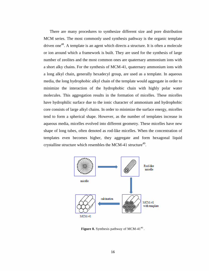
There are many procedures to synthesize different size and pore distribution
MCM series. The most commonly used synthesis pathway is the organic template
driven one48
. A template is an agent which directs a structure. It is often a molecule
or ion around which a framework is built. They are used for the synthesis of large
number of zeolites and the most common ones are quaternary ammonium ions with
a short alky chains. For the synthesis of MCM-41, quaternary ammonium ions with
a long alkyl chain, generally hexadecyl group, are used as a template. In aqueous
media, the long hydrophobic alkyl chain of the template would aggregate in order to
minimize the interaction of the hydrophobic chain with highly polar water
molecules. This aggregation results in the formation of micelles. These micelles
have hydrophilic surface due to the ionic character of ammonium and hydrophobic
core consists of large alkyl chains. In order to minimize the surface energy, micelles
tend to form a spherical shape. However, as the number of templates increase in
aqueous media, micelles evolved into different geometry. These micelles have new
shape of long tubes, often denoted as rod-like micelles. When the concentration of
templates even becomes higher, they aggregate and form hexagonal liquid
crystalline structure which resembles the MCM-41 structure49
.
Figure 8. Synthesis pathway of MCM-4146
.
17
CHAPTER 2
EXPERIMENTAL PROCEDURES
2.1 General
All chemicals and solvents purchased from Sigma-Aldrich and they were used
without further purification. 1H NMR and
13C NMR data were obtained using
Bruker DPX-400 in CDCl3 with TMS as internal reference. Splittings in spectra are
shown as s (singlet), d (doublet), t (triplet), q (quartet), m (multiplet). Column
chromatography for all products was performed by using Merck Silica Gel 60
(particle size: 0.040- 0.063 mm, 230-400 mesh ASTM).
Mass spectrometry was performed using MS-QTOF at Bilkent University,
UNAM, Mass Spectrometry Facility.
Absorption spectrometry was performed using Varian UV-Vis-NIR
Spectrophotometer. Fluorescence emission spectra were obtained by using Varian
Eclipse spectrofluorometer.
Particle size and zeta potential data were acquired by using Malvern Zetasizer
Nanoseries at Bilkent University, UNAM, Ankara.
XRD data were obtained by using PANalytical X’Pert Pro MPD Multi-purpose
X-ray diffractometer at Bilkent University, UNAM, Ankara.

18
SEM images were acquired in UNAM, Ankara, using Quanta 200 FEG,
Environmental Scanning Electron Microscopy. TEM images were obtained in
UNAM, Ankara, using FEI Technai G2 F30 high resolution transmission electron
microscope and carbon grid.
Analysis of Nitrogen Adsorption was done at METU, Central Laboratory,
Surface Characterization Unit, Ankara, by using Quantachrome Corporation,
Autosorb-6.

19
2.2 Synthesis of Photosensitizer
2.2.1 Synthesis of 4-(3-bromopropoxy)benzaldehyde (3)
Figure 9. Synthesis of compound 3
Hydroxybenzaldehyde (2 g, 16.4 mmol) and 1,6 dibromohexane (5.2 ml, 32.8
mmol) were dissolved in acetonitrile (150ml). K2CO3 (6.88 g, 49.2 mmol) and a few
crystals of 18-crown-6 were added. The reaction mixture was refluxed for 48 h.
Then acetonitrile was evaporated in vacuum and extracted with water and
chloroform. Organic phase was dried with Na2SO4 and evaporated by using rotary
evaporator. The product was purified by silica gel column chromatography using
CHCl3/Hexane (5:1, v/v). Fraction containing product 3 was collected then the
solvent was removed by using rotary evaporator. (2.4 g, 8.4 mmol, 51%).
1H NMR (CDCl3, 400MHz, δ ppm) 1.45 (m, 4H), 1.75 (t, J= 6.7Hz, 2H), 1.82 (t, J=
6.9Hz, 2H), 3.32 (t, J= 6.7Hz, 2H), 3.95 (t, J= 6.4Hz, 2H), 6.89 (d, J= 8.8Hz, 2H),
7.73(d, J= 8.7Hz,2H), 9.80 (s,1H)

20
2.2.2 Synthesis of 4-(3-azidopropoxy)benzaldeyhde (4)
Figure 10. Synthesis of compound 4
4-(3-Bromopropoxy)benzaldehyde (3, 1.5 g, 5.3 mmol ) was dissolved in
DMSO (25ml), NaN3 ( 1.37 g, 21.2 mmol) was added. Reaction mixture was heated
to 60oC for 3 hours. Extraction was done several times with water and chloroform
to get rid of DMSO. After the extraction, organic phase was dried with Na2SO4 and
evaporated by using rotary evaporator. The residual compound was liquid at room
temperature and pure.
1H NMR (CDCl3, 400MHz, δ ppm) 1.30-1.45 (m, 4H), 1.55 (t, J= 6.4Hz, 2H), 1.72
(t, J= 6.5Hz, 2H), 3.20 (t, J= 6.9Hz, 2H), 3.95 (t, J= 6.4Hz, 2H), 6.90 (d, J= 8.7Hz,
2H), 7.72 (d, J= 8.9Hz, 2H), 9.75 (s, 1H)
21
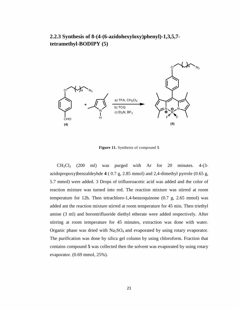
2.2.3 Synthesis of 8-(4-(6-azidohexyloxy)phenyl)-1,3,5,7-
tetramethyl-BODIPY (5)
Figure 11. Synthesis of compound 5
CH2Cl2 (200 ml) was purged with Ar for 20 minutes. 4-(3-
azidopropoxy)benzaldeyhde 4 ( 0.7 g, 2.85 mmol) and 2,4-dimethyl pyrrole (0.65 g,
5.7 mmol) were added. 3 Drops of trifluoroacetic acid was added and the color of
reaction mixture was turned into red. The reaction mixture was stirred at room
temperature for 12h. Then tetrachloro-1,4-benzoquinone (0.7 g, 2.65 mmol) was
added ant the reaction mixture stirred at room temperature for 45 min. Then triethyl
amine (3 ml) and borontrifluoride diethyl etherate were added respectively. After
stirring at room temperature for 45 minutes, extraction was done with water.
Organic phase was dried with Na2SO4 and evaporated by using rotary evaporator.
The purification was done by silica gel column by using chloroform. Fraction that
contains compound 5 was collected then the solvent was evaporated by using rotary
evaporator. (0.69 mmol, 25%).

22
1H NMR (CDCl3, 400MHz, δ ppm) 1.42 (s, 6H), 0.45-1.62 (m, 4H), 1.65 (t, J= 7.2,
2H), 1.85 (t, J= 7.3, 2H), 2.55 (s, 6H), 3.30 (t, J= 6.8, 2H), 4.03 (t, J= 6.4, 2H), 6.00
(s, 2H), 7.00 (d, J= 4.6), 7.18 (d, J= 4.6)
13C NMR (CDCl3, 100MHz, δ ppm) 14.6, 25.7, 26.6, 28.8, 29.1, 51.4, 67.9, 115.0,
121.2, 126.8, 129.2, 130.4, 131.8, 141.9, 143.2, 155.2, 159.6
HRMS-ESI: calculated for M+H 466.3464, found 466.2573, ∆m= 19 ppm
2.2.4 Synthesis of 8-(4-(6-azidohexyloxy)phenyl)-2,6-
dibromo1,3,5,7-tetramethyl-BODIPY (6)
Figure 12. Synthesis of compound 6
10-(4-(6-azidohexyloxy)phenyl)-2-8-dibromo-5,5-difluoro-1,3,7,9-tetramethyl-
5H-dipyrrolo[1,2-c:1',2'-f] [1,3,2]diazaborinin-4-ium-5-uide 6 (322 mg, 0.69 mmol)
was dissolved in a mixture of DMF/DCM (25ml:25ml). Then N-bromo succinimide
(370 mg, 2.07 mmol) was dissolved in DCM (25ml). NBS in DCM solution was
23
added to the reaction solution dropwise in 15 min. The reaction mixture was stirred
at room temperature for 2 hours. Followed by thin layer chromatography the
reaction was stopped and the extraction was done with water and DCM. The
organic phase was dried with Na2SO4 and evaporated by using rotary evaporator.
The purification was done by silica gel column by using chloroform/ hexane
mixture (3:1 v/v). Fraction that contains compound 6 was collected then the solvent
was evaporated by using rotary evaporator. (150 mg, 0.239 mmol, 35%)
1H NMR (CDCl3, 400MHz, δ ppm) 1.42 (s, 6H), 1.45-1.62 (m, 4H), 1.65 (t, J= 7.2,
2H), 1.85 (t, J= 7.3, 2H), 2.60 (s, 6H), 3.30 (t, J= 6.8, 2H), 4.03 (t, J= 6.4, 2H), 7.00
(d, J= 4.6, 2H), 7.18 (d, J= 4.6, 2H)
13C NMR (CDCl3, 100MHz, δ ppm) 13.7, 13.9, 25.7, 26.3, 27.0, 28.8, 29.1, 51.4,
68.0, 115.3, 126.3, 129.1, 130.8, 140.6, 142.4, 153.7, 160.1
HRMS- ESI: calculated for M+H 622.07, found 622.0727 ∆m= 4.3 ppm

24
2.2.5 Synthesis of compound 7
Figure 13. Synthesis of compound 7
Compound 6 (100 mg, 0.160 mmol) and 4-methoxybenzaldehyde (55mg, 0.40
mmol) dissolved in benzene (50 ml). Piperidine (0.4 ml) and glacial acetic acid (0.4
ml) were added respectively. The solution was refluxed by using Dean-Stark
apparatus. When the amount of solvent remained in the solution was minimized, the
reaction was followed by TLC until observing the green colored product had the
major band. Then the reaction was stopped and the extraction was done with
chloroform and water. The organic phase was dried with Na2SO4 and evaporated by
using rotary evaporator. The purification was done by silica gel column by using
chloroform as mobile phase. Fraction containing compound 7 was collected then
the solvent was evaporated under reduced pressure. (90 mg, 0.105 mmol, % 66)
1H NMR (CDCl3, 400MHz, δ ppm) 1.50 (m, 4H), 1.50 (s, 6H), 1.65 (t, J= 7.1 Hz,
2H), 1.90 (t, J= 7.2, 2H), 3.30 (t, J= 6.8, 2H), 3.88 (s, 6H), 4.08 (t, J= 6.3, 2H),

25
6.95 (d, J= 8.8, 4H), 7.04 (d, J= 8.6, 2H), 7.19 (d, J= 8.6, 2H), 7.65 (m, 2H+4H),
8.12 (d, J= 16.6, 2H)
13C NMR (CDCl3, 100MHz, δ ppm) 13.9, 15.4, 22.7, 25.8, 26.7, 29.2, 29.7, 31.6,
51.34, 55.4, 65.8, 68.0, 109.9, 114.4, 115.3, 116.2, 126.8, 129.3, 129.8, 132.48,
138.9, 141.0, 148.4, 160.0, 160.9
2.2.6 Synthesis of 3-isothiocyanatoprop-1-yne (8)
Figure 14. Synthesis of compound 8
Propargyl amine (401.5 ml, 7.3 mmol) and triethyl amine (2216 mg, 21.9 mmol)
was added to THF solution (10 ml) and the solution was cooled with an ice bath
under Ar for 30 minutes. Then CS2 (556 mg, 7.3 mmol) was added to the reaction
mixture dropwise over 30 minutes with vigorous stirring. After the addition was
completed, the mixture was stirred at room temperature for 1 h. Then, the reaction
mixture was cooled with an ice bath and TsCl (1540 mg, 8.103 mmol) was added
and then stirred for half an hour at room temperature.
At last, HCl (1N, 10ml) and diethylether (10ml) were added to the solution and
extracted several times with small amount of diethyl ether. The organic phase was
26
dried with Na2SO4 and evaporated under reduced pressure. The purification was
done by silica gel column by using hexane/chloroform mixture (10:1.5 v/v) as
mobile phase. Fraction containing compound 8 was collected then the solvent was
evaporated by rotary evaporator. The residual was yellow liquid with odor. (400
mg, 4.1 mmol, %56)
13C NMR (CDCl3, 100MHz, δ ppm) 14.1, 31.6, 35.0, 73.8
HRMS-ESI: calculated 97.00, found 96.9592 ∆m= 42 ppm
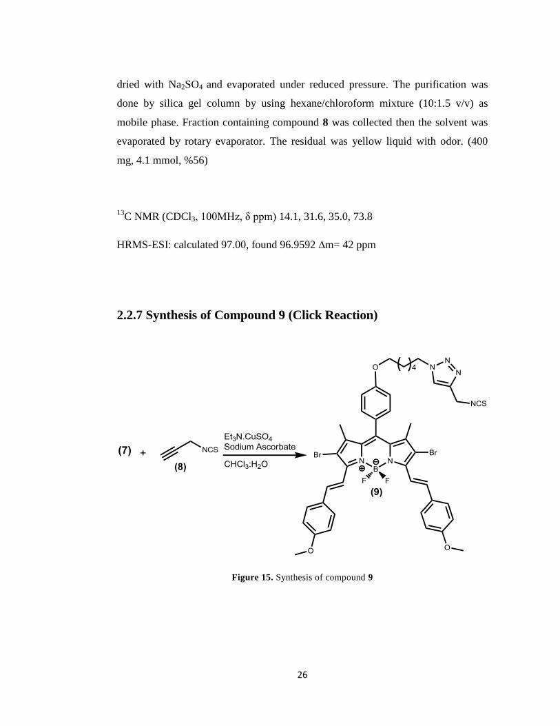
2.2.7 Synthesis of Compound 9 (Click Reaction)
Figure 15. Synthesis of compound 9
27
Synthesis was done following the procedure in literature50
. Compound 7 (80
mg, 0.093 mmol) and compound 8 (27 mg, 0.279 mmol) was dissolved in CHCl3 (6
ml). A few drops of triethyl amine were added to the reaction and the mixture was
stirred for 5 minutes at room temperature. In a vial, CuSO4 (5 mg) dissolved in
water (0.7 ml). In another vial, sodium ascorbate (8 mg) was dissolved in water (0.7
ml). CuSO4 and sodium ascorbate solutions were added to the reaction mixture in
turn. The reaction mixture was stirred at room temperature for 48 h. Then the
extraction was done with CHCl3 and water. Organic layer was dried with Na2SO4
and evaporated under reduced pressure. The purification was done by silica gel
column by using CHCl3 as mobile phase. Fraction was collected and the solvent was
removed by using rotary evaporator. (20 mg, 0.021 mmol, 23%)
1H NMR (CDCl3, 400MHz, δ ppm) 1.30 (m, 4H), 1.50 (s, 6H), 1.85 (t, J= 7.9 Hz,
2H), 2.05 (t, J= 7.5, 2H), 3.88 (s, 6H), 4.05 (t, J= 6.4, 2H), 4.43 (t, J= 7.2, 2H), 4.88
(s, 2H), 6.82 (d, J= 8.8, 4H), 7.04 (d, J= 8.6, 2H), 7.19 (d, J= 8.6, 2H), 7.65 (m,
2H+4H+1H), 8.14 (d, J= 16.6, 2H)
13
C NMR (CDCl3, 100MHz, δ ppm) 14.0, 25.6, 26.6, 29.1, 29.8, 30.3, 41.1, 50.7,
55.5, 67.9, 114.3, 115.3, 116.2, 121.6, 126.9, 128.8, 129.3, 129.7, 129.88, 130.93,
132.5, 138.8, 141.0, 148.4, 160.0, 160.8
MALDI: calculated 956.54 and found 956.16
2.2.8 Synthesis of MSNs
The synthesis was done according to the procedure in literature53
.
Cetylammonium bromide (CTAB) (0.1g) was dissolved in NH4OH (50 g, 0.51 M)
at 50oC and tetraethyl orthosilicate (TEOS) ( 0.8 ml, 0.2 M in ethanol) was added
under continous stirring. After stirring 5 hours, 3-aminopropyltrimethoxysilane
(APTMS) (0.8 ml of 12% (v/v) in ethanol) and TEOS (0.8 ml of 1M) were added to
the solution and stirred for 1 hour. The solution was stirred for 24 hours at 50oC.
28
The solution was centrufuged and the precipitates were collected by washing
with deionized water and ethanol several times. In order to remove surfactant
templates particles were added to acidic ethanol (3 ml concentrate HCl in 100 ml of
ethanol) and stirred 24 hours at 65 oC.
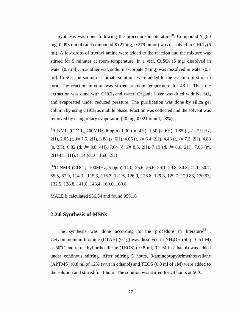
2.2.9 Synthesis of PS-MSNs
Compound 9 (10 mg) was added into distilled THF (6 ml). MSNs (60 mg) was
added to the reaction mixture and the mixture was stirred for 2 days at room
temperature. After 2 days, the mixture was centrufuged and washed with
chloroform to get rid off the unreacted compound 9. This process was continued
until there observed no color in the solution of centrufuged mixture.
The solid particles were taken and were left to dry at room temperature.
Figure 16. Schematic drawing of PS-MSNs

29
CHAPTER 3
RESULTS AND DISCUSSION
3.1 MSNs as a Carrier System for Photosensitizer
Mesoporous silica nanoparticles are convenient carrier system for drugs when
their unique properties such as; large surface areas, uniform pore sizes,
hydrophilicity, acquiring targeting by surface modification and low cytotoxicity are
considered. Photodynamic therapy, treatment of cancer cells by using
photosensitizers along with light, growing interest of research recently. This way of
therapy has numerous advantages over other types of cancer treatment. Since PDT
maintains the treatment of tumors locally, it minimizes the damages to the
surrounding healthy tissue. Photosensitizers tend to localize in cancer tissues more
than the healthy tissues and the exposure of light to only cancer tissue provides
further selectivity.
3.1.1 Design of Photosensitizer
In this study, we have designed a novel photodynamic therapy reagent based on
BODIPY derivative where MSNs are used as carrier system. The reason for
selecting BODIPY as photosensitizer is its stability under light, high extinction
coefficient and ease of modification of its core. For instance, modification of
BODIPY at 1,3,5,7 positions with styryl groups was reported by Akkaya et al.
recently35
. Here, we modified 3, 5 positions by Knoevenagel condensation reactions

30
and obtained distyryl-BODIPY. The aim of this modification was to move
absorption and emission bands of the compund further into the red end of the
visible spectrum.
Bromination of the 2, 6 positions were done in order to increase spin-orbit
coupling by introducing heavy atom. With this modification, transition from singlet
excited state of photosensitizer to triplet state is enhanced51
. In order to attach
photosensitizer to mesoporous silica nanoparticles, isothiocyanate functional group
was attached to photosensitizer by click reaction. Characterization of all
compounds were done by using 1H and
13C NMR spectra and Mass spectrometry
analysis and are given in the appendices A and B.
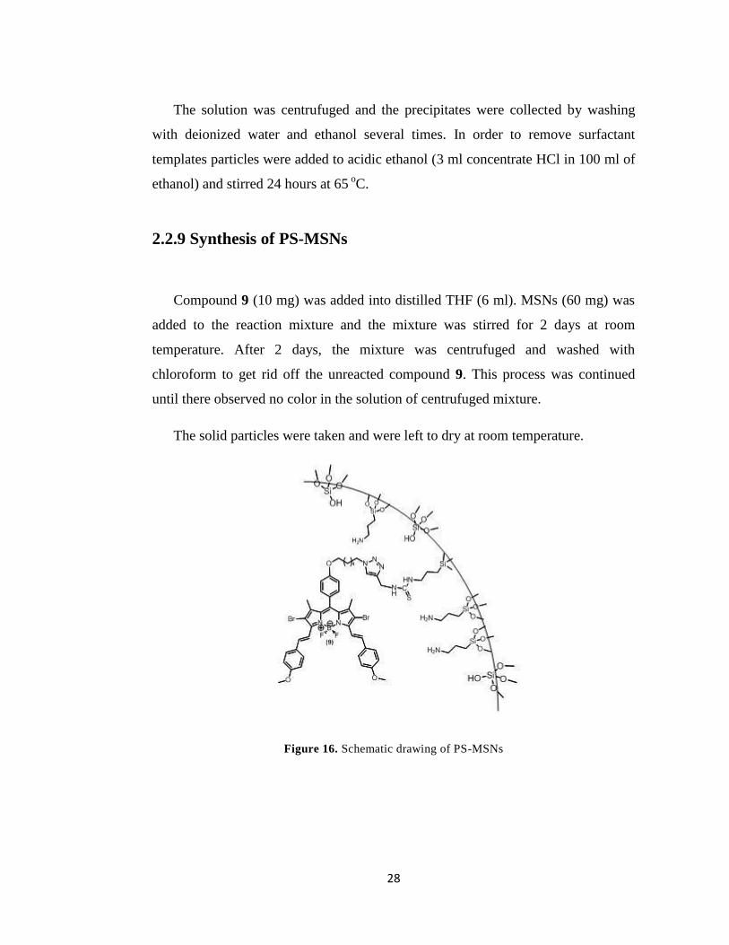
The absorbance maxima of the photosensitizer is at 653 nm which is convenient
for photodynamic therapy since it is in the range of therapeutic window of body.
(Figure 17.) The fluorescence emission maxima is at 678 nm (Figure 18.).
Figure 17. Absorbance of compound 9 in CHCl3
31
Figure 18. Fluorescense emission of compound 9 in CHCl3. Excitation is at 650 nm.
3.1.2 Design of MSNs
MSNs were sytnhesized with low-concentration of TEOS, CTAB as surfactant
and base-catalyst NH4OH. In order to modify the surface of MSNs with
photosensitizer, MSNs-APTS was synthesized. For this aim, sol gel process was
applied by co-condensation of TEOS with APTS (3-aminopropyl-trimethoxy
silane). The as synthesized particles were characterized by several characterization
methods.
32
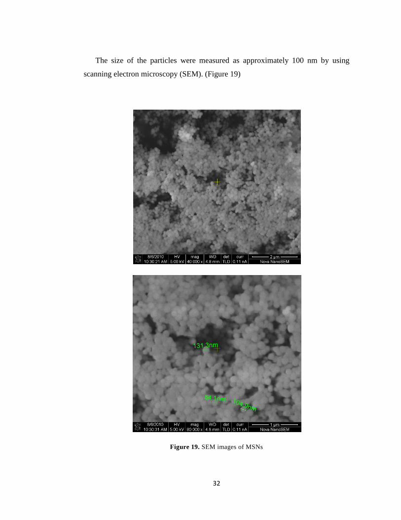
The size of the particles were measured as approximately 100 nm by using
scanning electron microscopy (SEM). (Figure 19)
Figure 19. SEM images of MSNs
33
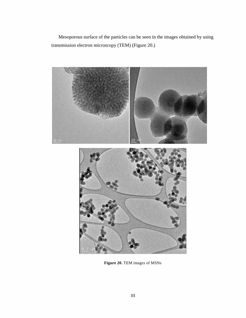
Mesoporous surface of the particles can be seen in the images obtained by using
transmission electron microscopy (TEM) (Figure 20.)
Figure 20. TEM images of MSNs
34
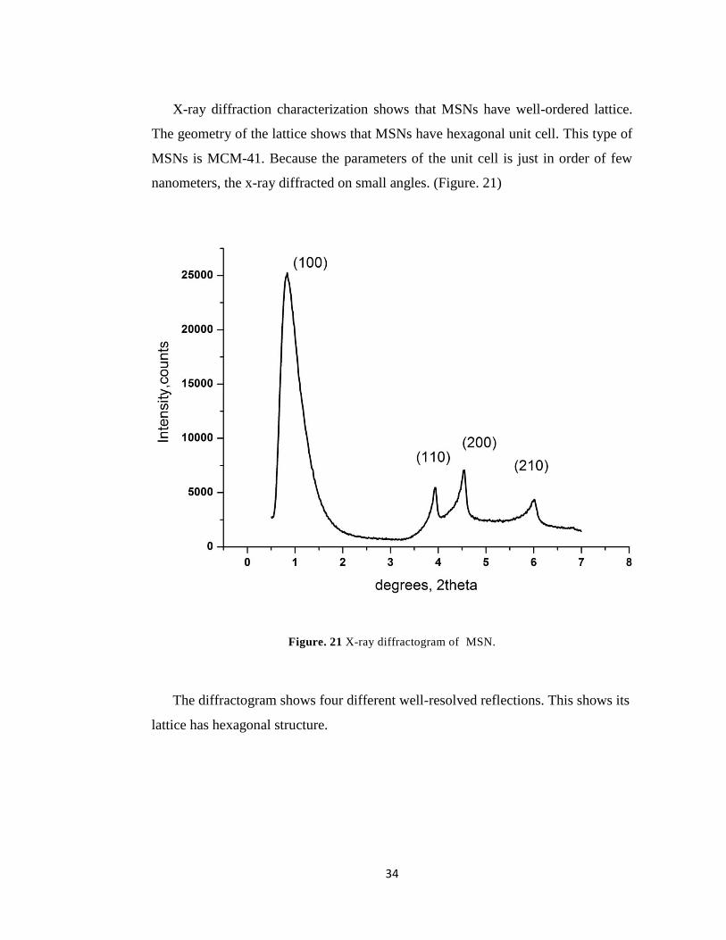
X-ray diffraction characterization shows that MSNs have well-ordered lattice.
The geometry of the lattice shows that MSNs have hexagonal unit cell. This type of
MSNs is MCM-41. Because the parameters of the unit cell is just in order of few
nanometers, the x-ray diffracted on small angles. (Figure. 21)
Figure. 21 X-ray diffractogram of MSN.
The diffractogram shows four different well-resolved reflections. This shows its
lattice has hexagonal structure.
35
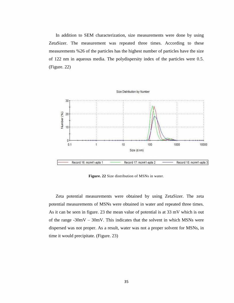
In addition to SEM characterization, size measurements were done by using
ZetaSizer. The measurement was repeated three times. According to these
measurements %26 of the particles has the highest number of particles have the size
of 122 nm in aqueous media. The polydispersity index of the particles were 0.5.
(Figure. 22)
Figure. 22 Size distribution of MSNs in water.
Zeta potential measurements were obtained by using ZetaSizer. The zeta
potential measurements of MSNs were obtained in water and repeated three times.
As it can be seen in figure. 23 the mean value of potential is at 33 mV which is out
of the range -30mV – 30mV. This indicates that the solvent in which MSNs were
dispersed was not proper. As a result, water was not a proper solvent for MSNs, in
time it would precipitate. (Figure. 23)

36
Figure. 23 Zeta potential distribution of MSNs
Nitrogen adsorption (physisorption) analysis characterizes the texturel
properties of materials such as surface area, pore size, pore volume and pore
geometry. The nitrogen isotherm of MCM-41 is shown in Figure 24. Both
adsorption (black line) and desorption data (red line) are shown. As it can be seen in
the graph, there are five districts. This isotherm is a typical MCM-41 isotherm.
Accroding to BET analysis, the surface area of the particle is 1036 m2/g, pore
volume is 1.678 cc/g, pore size is 3.082 nm. The outgas temperature was 150oC and
the outgas time was 3 hours. (Figure 24)
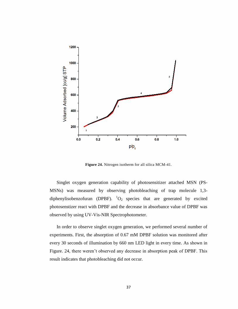
37
Figure 24. Nitrogen isotherm for all silica MCM-41.
Singlet oxygen generation capability of photosensitizer attached MSN (PS-
MSNs) was measured by observing photobleaching of trap molecule 1,3-
diphenylisobenzofuran (DPBF). 1O2 species that are generated by excited
photosenstizer react with DPBF and the decrease in absorbance value of DPBF was
observed by using UV-Vis-NIR Spectrophotometer.
In order to observe singlet oxygen generation, we performed several number of
experiments. First, the absorption of 0.67 mM DPBF solution was monitored after
every 30 seconds of illumination by 660 nm LED light in every time. As shown in
Figure. 24, there weren’t observed any decrease in absorption peak of DPBF. This
result indicates that photobleaching did not occur.
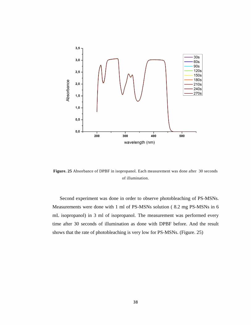
38
Figure. 25 Absorbance of DPBF in isopropanol. Each measurement was done after 30 seconds
of illumination.
Second experiment was done in order to observe photobleaching of PS-MSNs.
Measurements were done with 1 ml of PS-MSNs solution ( 8.2 mg PS-MSNs in 6
mL isopropanol) in 3 ml of isopropanol. The measurement was performed every
time after 30 seconds of illumination as done with DPBF before. And the result
shows that the rate of photobleaching is very low for PS-MSNs. (Figure. 25)
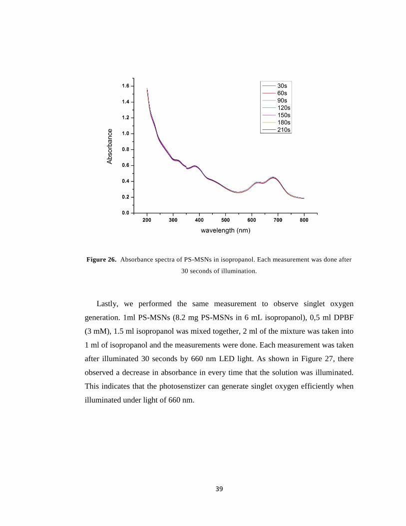
39
Figure 26. Absorbance spectra of PS-MSNs in isopropanol. Each measurement was done after
30 seconds of illumination.
Lastly, we performed the same measurement to observe singlet oxygen
generation. 1ml PS-MSNs (8.2 mg PS-MSNs in 6 mL isopropanol), 0,5 ml DPBF
(3 mM), 1.5 ml isopropanol was mixed together, 2 ml of the mixture was taken into
1 ml of isopropanol and the measurements were done. Each measurement was taken
after illuminated 30 seconds by 660 nm LED light. As shown in Figure 27, there
observed a decrease in absorbance in every time that the solution was illuminated.
This indicates that the photosenstizer can generate singlet oxygen efficiently when
illuminated under light of 660 nm.

40
Figure 27. Bleaching of DPBF in the presence of PS-MSNs.

41
CHAPTER 4
CONCLUSION
In this study, novel BODIPY-based photodynamic therapy reagent and a carrier
system were designed, synthesized and characterized. We studied to modify
BODIPY dye to attach MSNs covalently. The photosenstizer has a 653 nm
absorption maxima which makes it a good candidate to be used in PDT.
We synthesized MCM-41 type MSNs in order to use as drug carrier system. We
used the instruments SEM, TEM, XRD, ZetaSizer in order to characterize MSNs.
Since MSNs have amine groups on surface, it is easy to modify them in order to
enhance targeting.
Singlet oxygen generation experiments show that the compound 9 is a good
singlet oxygen generator and the carrier system does not influence the efficiency of
singlet oxygen generation.
In conclusion, we have demonstrated that for PDT, MSNs can be used in the
delivery of PS with the low toxicity, uniform pores, easily modified surface of
MSNs and BODIPY dyes are good PSs with the efficent singlet oxygen generation.
42
REFERENCES
1. Weishaupt, K.R.; Gomer, C.J.; Dougherty, T.J; Cancer Res., 1976, 36, 2326
2. Dougherty, T.J.; Gomer, C.J.; Henderson, B.W.; Jori, G.; Kessel, D.;
Korbelik, M.; Moan, J.; Peng, Q.; J. Natl. Cancer Inst., 1998, 90, 889
3. Detty, M.R.; Gibson, S.L.; Wagner, S.L.; J. Med. Chem., 2004, 47, 3897
4. Henderson, B.W.; Dougherty, T.J.; Photochem Photobiol, 1992, 55, 145
5. Moan, J.; Berg, K.; Photochem. Photobiol., 1991, 53, 549
6. Spikers, J.D. Primary Progresses in Biology and Medicine. Plenum Press,
New York, 1985, 209
7. Reed, M.; Ackroyd, R.; Kelty, C.; Brown, N.; Photochem Photobiol, 2001,
74, 656
8. Finsen, N.R.; Phototherapy, Edward Arnold, London, 1901.
9. Fitzpatrick, T.B.; Pathak, M.A.; J. Investig. Dermatol., 1959, 23, 229
10. Von Tappeiner, H.; Jesionek, A.; Muench. Med. Wochenschr. 1903, 47, 5
11. Von Tappeiner, H.; Jodlbauer, A.; Gesammte Untersuchung uber die
photodynamische Erscheinung, F.C.W. Vogel, Leipzig, 1907.
12. Hausmann, W. Biochem., 1911, 30, 276.
13. Meyer-Betz, F., Dtsch. Arch. Klin. Med. 1913, 112, 476
14. Dougherty, T.J., Cancer Res., 1978, 36, 2628
15. Kelly, J.F.; Snell, M.E., J. Urol., 1976, 115, 150
43
16. Sandeman, D.R., Lasers Med. Sci., 1986, 1, 163
17. Schweitzer, V.G., Otolaryngol. Head Neck Surg., 1990, 102, 225
18. Barr, H.; Krasner, N.; Boulos, P.B.; Chatlani, P.; Bown, S.G., Br. J. Surg.,
1990, 77, 93
19. Ward, B.G.; Forbes, I.J.; Cowled, P.A.; McEvoy, M.M.; Cox, L.W., Am. J.
Obstet. Gynecol., 1982, 142, 356
20. Triesscheijn, M.; Baas, P.; Schellens, J.H.M.; Stewart, F.A.; The
Oncologist, 2006, 11, 1034
21. Gomer, C.J.; Photodynamic Therapy, Methods in Molecular Biology,
Springer Science+Business Media, 2010
22. Castano, A.P.; Mroz, P.; Hambli, M.R. Nature Reviews Cancer, 2006, 6,
535
23. Reed, M.W.; Wieman, T.J.; Schuschke, M.T.; Miller, F.N., Radiot. Res. ,
1989, 119, 542.
24. Peng, Q.; Moan, J.; Nesland, J.M.; Ultrastruc. Pathol., 1996, 20, 109.
25. Kessel, D.; Luo, Y., J. Photochem. Photobiol., 1998, 42, 89.
26. Spikes, J.D.; Bommer, J.C. Photochem. Photobiol., 1993, 58, 346.
27. Wang, R.K.; Tuchin, V.V., Proc. SPIE, 2003, 4956, 314
28. Brown, B.; Brown, E.A.; Walker, I., Lancet Oncol., 2004, 5, 497
29. Gilson, D.; Ash, D.; Driver, I., Br. J. Cancer, 1988, 58, 665
30. Moriowaki, S.I.; Yoshinari, Y., Photodermatol. Photoimmunol. Photomed.,
2001, 17, 241

44
31. Loudet, A.; Burgess, K., Chem. Rev., 2007, 107,4891
32. Karolin, J.; Johansson, L.B.A.; Strandberg, L.; Ny, T., J. Am. Chem. Soc. ,
1994, 116, 7801
33. Metzker, M.L., WO Patent WO/2003/066812, 2003
34. Ozlem S.; Akkaya E. U. J. Am. Chem. Soc., 2009, 131, 48.
35. Yogo, T.; Urano, Y.; Ishitsuka, Y.; Maniwa, F.; Nagano, T. J. Am. Chem.
Soc., 2005, 127, 12162.
36. Atilgan, S.; Ekmekci, Z.; Dogan, A. L.; Guc, D.; Akkaya, E. U. Chem.
Commun., 2006, 4398.
37. Buyukcakir, O.; Bozdemir, A.O.; Kolemen,S.; Erbas, S.; Akkaya, E.U., Org.
Let., 2009, 11, 4644
38. Van Nostrum, C.F., Adv. Drug Delivery Rev. ,2004, 56,9
39. Wang, S.; Gao, R.; Zhou, F.; Selke, M., J. Mater. Chem., 2004, 14, 487.
40. Ohulchanskyy, T.Y.; Roy, I.; Goswami, L.N.; Chen, Y.; Bergey, E.J.;
Pandey, R.K.; Oseroff, A.R.; Prasad, P.N., Nano Lett., 2007, 7, 2835.
41. Zhang, P.; Steelant, W.; Kumar, M.; Scholfield, M., J. Am. Chem. Soc.,
2007, 129, 4526.
42. F. Iskandar, I.W. Lenggoro, T.O. Kim, N. Nakao, M. Shimada, K.
Okuyama, J. Chem. Eng. Jpn., 2001, 34, 1285.
43. Le Paige, M., France, US Patent, 3493341, 1970
44. Yanagisawa, T.; Shimizu, T; Kuroda, K; Kato, C.; Bull. Chem. Soc. Jpn.,
1990, 63, 988

45
45. Kresge, C.T.; Leonowicz, M.E.; Roth, W.J.; Vartuli, J.C.; Beck, J.S.;
Nature, 1992, 359, 710.
46. Kresge, C.T.; Leonowicz, M.E.; Roth, W.J.; Vartuli, J.C.; Beck, J.S.;
Schmitt, K.D.; Chu, C.T-W.; Olson, D.H.; Sheppard, E.W.; McCullen, S.
B.; Higgins, J.B.; Schlenker, J.L., J. Am. Chem. Soc., 1992, 114, 10834.
47. Zhao. D., Science, 1998, 279, 548.
48. S.A. Johnson, P.J. Ollivier, T.E. Mallouk, Science, 1999, 283, 963.
49. Lensveld, D., On the preparation and characterization of MCM-41
supported heterogeneous nickel and molybdenum catalysts, Proefschrift
Universitat Utrecht, 2003.
50. Turro, N.J. In Modern Molecular Photochemistry; University Science
Books; Sausalito, CA, 1991, pp 191-195.
51. Wyszogrodzka, M.; Haag, R. Chem. Eur. J. ,2008, 14, 9202.
52. Cheng, S.; Lee, C; Yang, C.; Tseng, F.; Mou, C.; Lo, L.; J.Mater. Chem.;
2009, 19, 1252.
46
APPENDİX A
Figure 28. 1H NMR of compound 3

47
Figure 29. 1H NMR of compound 4

48
Figure 30. 1H NMR of compound 5

49
Figure 31. 1H NMR of compound 6

50
Figure 32. 1H NMR of compound 7

51
Figure 33. 1H NMR of compound 9
52
Figure 34. 1H NMR of compound 9 (aromatic region)

53
Figure 35. 13
C NMR of compound 5
54
Figure 36. 13
C NMR of compound 6
55
Figure 37. 13
C NMR of compound 7
56
Figure 38. 13
C NMR of compound 8

57
Figure 39. 13C NMR of compound 9

58
APPENDİX B
Figure 40. ESI-HRMS of compound 5
Figure 41. ESI-HRMS of compound 6
59
Figure 42. ESI-HRMS of compound 8

60
Figur 43. MALDI-MS of compound 9