metal enclosed load break interrupter switchgear … · pcib-1008-c instruction book metal enclosed...
TRANSCRIPT

PCIB-1008-C
INSTRUCTION BOOK
METAL ENCLOSED LOAD BREAKINTERRUPTER SWITCHGEAR
(Visual-Audio VHS Tapes on Safety, Maintenance, Inspection, and Operation are recommendedfor use with this Instruction Book. Order TP002 Parts 1, 2, 3)
IN ADDITION TO THE PERSONNEL PROTECTION PRECAUTIONS AS OUTLINED WITHIN, REFER TO ANSISTANDARD Z 244.1-1982, ENTITLED:
PERSONNEL PROTECTION - LOCKOUT/TAGOUT OF ENERGY SOURCES MINIMUM SAFETY REQUIREMENTS.
*************These instructions may not cover all details or variations in equipment, nor provide for every possible contingency encountered.Should further information be desired or should problems arise which are not covered sufficiently, the matter should be referred
to the POWERCON CORPORATIONP.O. Box 477, 1551 Florida Avenue, Severn, MD 21144 Phone: 410-551-6500 email [email protected]
PCIB-1008C 2
BEFORE CHECKING OR MAINTENANCE OFSWITCHGEAR, AFTER IT HAS BEEN INSTALLED - THEFOLLOWING MUST BE OBSERVED: ONLYQUALIFIED PERSONS MAY OPERATE, INSPECT ORMAINTAIN POWER SWITCHGEAR. IN ADDITION TOTHE PERSONNEL YOU MAY HAVE WHO AREQUALIFIED, OTHERS MAY BE AVAILABLE FROM ANEXPERIENCED HIGH VOLTAGE CONTRACTOR ORTHE UTILITY SERVICING THE INSTALLATION. IT ISTHE RESPONSIBILITY OF THE PURCHASER,INSTALLER, OR ULTIMATE USER TO INSURE THATTHE WARNING SIGNS AR NOT REMOVED AND TOMAKE SURE THAT ALL ACCESS DOORS, ANDOPERATING HANDLES ARE SECURELY LOCKEDWHEN THE GEAR IS LEFT UNATTENDED BYQUALIFIED PERSONS, EVEN MOMENTARILY.
DO NOT REMOVE COVERS, OPEN DOORS, OR WORK ON EQUIPMENT UNLESSPOWER HAS BEEN TURNED OFF AND ALL CIRCUITS DE-ENERGIZED ANDDISCONNECTED. DISCONNECT, DE-ENERGIZE, LOCKOUT AND PROPERLYGROUND CIRCUIT(S) BEFORE WORKING ON THIS EQUIPMENT. USE PROPERSAFETY PRECAUTIONS WHEN WORKING ON THIS EQUIPMENT.
ALL SAFETY CODES, SAFETY STANDARDS, AND/OR REGULATIONS AS THEYMAY BE APPLIED OT THIS TYPE OF EQUIPMENT MUST BE STRICTLY ADHEREDTO . BEFORE ANY ADJUSTMENTS, SERVICING, PARTS REPLACEMENT OR ANYOTHER ACT IS PERFORMED REQUIRING ANY PHYSICAL CONTACT WITH THEELECTRICAL COMPONENTS OR WIRING OF THIS EQUIPMENT, THE POWERSUPPLY MUST BE DISCONNECTED.
IN ADDITION TO THE PERSONNEL PRECAUTIONS AS OUTLINED, REFER TO:
• • Z244.1-1982 PERSONNEL PROTECTION LOCKOUT/TAGOUT OF ENERGYSOURCES MINIMUM SAFETY REQUIREMENTS
• • ANSI/NFPA 70E-1988: ELECTRICAL SAFETY REQUIREMENTS FOREMPLOYEE WORKPLACES
• ANSI/NFPA 70B-1988: ELECTRICAL EQUIPMENT MAINTENANCE
THE EQUIPMENT COVERED BY THIS INSTRUCTION BOOK MUST BE SELECTEDFOR A SPECIFIC APPLICATIONS AND IT MUST BE INSTALLED, OPERATED, ANDMAINTAINED BY QUALIFIED PERSONS WHO ARE THOROUGHLY TRAINED AND
WHO UNDERSTAND ALL OF THE HAZARDS INVOLVED. As with any electricalapparatus, the thorough knowledge of the engineering safety, inspection, maintenance
and repair techniques as well as being familiar with particular features of theapparatus involved is mandatory. THIS BOOK DOES NOT PROVIDE SUFFICIENT
INSTRUCTIONS FOR INEXPERIENCED ELECTRICIANS OR UNQUALIFIEDPERSONS TO DO ANY WORK REQUIRED INCLUDING THE HANDLING,
INSTALLATION, TESTING, OPERATION, INSPECTION, MAINTENANCE, ANDREPAIR.
[SAFETY GROUNDING TO BE DONE ON DE-
ENERGIZED EQUIPMENT ONLY.Before energizing the equipment and prior to any
testing it is recommended that all circuits be safelygrounded. Prior to any grounding whether it be forany testing, inspection, or maintenance procedures,
assure that all safety precautions are taken. It isfurther recommended that an appropriate properlyoperating glow tube instrument that lights up and
warns the worker when held in any alternatingcurrent field, indicating the presence of voltage, be
used prior to grounding.
PERSONNEL DOING SUCH WORK SHOULD WEARLINEMAN’S PROTECTIVE EQUIPMENT INACCORDANCE WITH SUCH EQUIPMENT
MANUFACTURER’S RECOMMENDATIONSINCLUDING BUT NOT LIMITED TO PROTECTIVE
GLOVES, INSULATED SLEEVES, LINEMAN’SBLANKETS, INSULATED HELMETS, FACE AND EYE
PROTECTION that will assist in preventing injury if forany reason the equipment is grounded to an energizedcircuit. Every precaution should be taken to prevent
electrical grounding on an energized circuit. Suitablegrounding clamp leads should be used and safety grounding
techniques employed. ALL SUCH GROUNDS MUST BEREMOVED AFTER TESTING, INSPECTION, ORMAINTENANCE PRIOR TO ENERGIZING THE
EQUIPMENT.
In as much as Powercon has no control over the useto which others may put this material, statements
concerning uses of the materials described herein arenot to be construed as suitable for these used unless
proper technology in he usage, applications, andmaintenance are strictly observed. For further
information call or write the Powercon Corporation.
WARNINGIMPORTANT
IT IS IMPERATIVE THAT YOU READ AND COMPLETELYUNDERSTAND THE WARNING LOCATED TO THE RIGHT OF THISBLOCK, FAILURE TO DO SO CAN RESULT IN DAMAGE TOPROPERTY, PERSONAL INJURY OR DEATH

PCIB-1008C 3
LIMITED WARRANTY
Powercon warrants that the equipment we deliver will be of the kind and quality described in the order or contract and will be free ofdefects in workmanship and material. Should any failure to conform to this warranty appear within one year after date of shipment,Powercon shall upon prompt notification thereof and substantiation that the equipment has been stored, installed, operated andmaintained in accordance with Powercon recommendations and standard industry practice, correct such nonconformities, at its option,either by repairing any defective part or parts or by supplying a repaired or replacement part or parts F.O.B. factory. However, ifPowercon has installed the equipment or furnished field engineering services with respect to its installation, and provided suchinstallation has not been delayed by the Purchaser, said one year shall run from the completion of the installation. The total warrantyperiod shall not exceed 18 months from the date of shipment in any case.
In no event shall Powercon be responsible for providing working access to the defect, including the removal, disassembly, replacementor reinstallation of any equipment material or structures to the extent necessary to permit Powercon to perform its warranty obligations,or transportation costs to and from the Powercon factory or repair facility. The conditions of any tests shall be mutually agreed uponand Powercon shall be notified of, and may be present at, all tests that may be made.
THE WARRANTIES SET FORTH IN THIS PROVISION ARE EXCLUSIVE AND IN LIEU OF ALL OTHERWARRANTIES WHETHER STATUTORY, EXPRESS OR IMPLIED (INCLUDING ALL WARRANTIES OFMERCHANTABILITY AND FITNESS FOR PARTICULAR PURPOSE AND ALL WARRANTIES ARISING FROMCOURSE OF DEALING OR USAGE OF TRADE), EXCEPT OF TITLE AND AGAINST PATENT INFRINGEMENT. Theremedies provided above are the purchaser’s sole remedies for any failure of Powercon to comply with its obligations. Correction ofany nonconformity in the manner and for the period of time provided above shall constitute complete fulfillment of all the liabilities ofPowercon whether the @ of the Purchaser are based in contract, in tort (including negligence) or otherwise with respect to or arisingout of the equipment furnished hereunder.
WARRANTY IMPLEMENTATIONS AND CONDITIONS
On those occasions where service help is required, the Powercon Corporation should be notified at once through its ServiceDepartment. No charges Or expenses should be incurred except as authorized by the Corporation in writing. Making unauthorizedcorrections or doing unauthorized work voids this Warranty and renders reimbursement impossible.
At times, the Powercon Corporation may request labor and/or material services from you. At our option we will provide competentsupervision who will authorize such services by signing the Time Sheets of the people involved. No reimbursement can be madewithout signed Time Sheets.
The services rendered must be of the type and quality satisfactory to the Powercon Corporation, and we reserve the right to reject anyand all such services.
The above in no way prejudices the right of the Powercon Corporation to correct, as stipulated in the Warranty, any problems that mayoccur in equipment manufactured by the Powercon Corporation.
PCIB-1008C 4
FOREWORD
The warranty associated with this equipment is fully described with its implementation on Page i. It should be emphasized that unlessapproved by the Powercon Corporation no modification, alteration, change or correction should be undertaken without such expressauthority provided in writing by an authorized Powercon representative.
This Instruction Book is furnished in "As is" condition. No warranties expressed or implied, including warranties of fitness for aparticular purpose, or merchantability, or warranties arising from course of dealing or usage of trade are made regarding theinformation, recommendations, descriptions, and safety notations contained herein. In no way will Powercon be responsible to theuser in contract, in tort (including negligence), strict liability or otherwise for any direct special, indirect, incidental, or consequentialdamage or loss whatsoever, including but not limited to damage or loss of use of equipment, plant, or power system, cost of capital,loss of profits or revenues, cost of replacement power, additional expenses in the use of existing power facilities, or claims against theuser by its customer resulting from the use of information, recommendations, descriptions, and safety notations contained herein.
The information, recommendations, descriptions, and safety notations in this document are based on Powercon's experience andjudgment in respect to all of the subject matter contained herein. This information must not be considered to be all inclusive orcovering all contingencies.
QUALIFIED PERSONNEL ONLY
The equipment covered by this Instruction Book must be selectedfor a specific application and it must be installed, operated andmaintained by qualified persons who are thoroughly trained andwho understand all of the hazards involved. As with any electricalapparatus the thorough knowledge of the engineering safety,inspection, maintenance and repair techniques and familiarity withparticular features of the apparatus involved is mandatory. Thisbook does not provide sufficient instructions for inexperiencedelectricians or unqualified persons to do any work requiredincluding the handling, installation, testing, operation, inspection,maintenance, and repair. Refer to OSHA 29CFR Part 1910.399for definition of "qualified person".
WARNINGSAFETY GROUNDING
TO BE DONE ON DE-ENERGIZED EQUIPMENT ONLY
Before energizing the equipment and prior to any testing or maintenance itis recommended that all circuits be safely grounded. Prior to anygrounding whether it be for any testing, inspection, or maintenanceprocedures, assure that all safety precautions are taken. It is furtherrecommended that an appropriate properly operating glow tubeinstrument that lights up and warns the worker when held in any alternatingcurrent field, indicating the presence of voltage, be used prior togrounding
Personnel doing such work should wear lineman's protectiveequipment in accordance with such equipment manufacturer'srecommendations including but not limited to protective gloves,insulated sleeves, lineman's blankets, insulated helmets, face andeye protection that will assist in preventing injury if for any reason theequipment is grounded to an energized circuit. Every precaution shouldbe taken to prevent electrical grounding on an energized circuit. Suitablegrounding clamp leads should be used and safety grounding techniquesemployed. All such grounds must be removed after testing, inspection,or maintenance prior to energizing the equipment.
The above in no way replaces the user's safety techniques orapplicable safety codes, rules, or regulations.
WARNINGIMPORTANT
IT IS IMPERATIVE THAT YOU READ AND COMPLETELYUNDERSTAND THE WARNING LOCATED TO THE RIGHTOF THIS BLOCK, FAILURE TO DO SO CAN RESULT INDAMAGE TO PROPERTY, PERSONAL INJURY OR DEATH
WARNINGIMPORTANT
IT IS IMPERATIVE THAT YOU READ AND COMPLETELYUNDERSTAND THE WARNING LOCATED TO THE RIGHTOF THIS BLOCK, FAILURE TO DO SO CAN RESULT INDAMAGE TO PROPERTY, PERSONAL INJURY OR DEATH

PCIB-1008C 5
PLAN YOUR INSTALLATION
In addition to planning for installation of Powercon manufactured equipment, consideration must be given to receiving and handling.Included below are some of the problems that can occur with inadequate planning. Accordingly, please note shipping sections, andweights and dimensions as noted on the drawings.
PCIB-1008C 6
TABLE OF CONTENTS
PLAN YOUR INSTALLATION................................ ................................ ................................ .......................... 5
INTRODUCTION................................ ................................ ................................ ................................ ................... 7
APPLICATION................................ ................................ ................................ ................................ ...................... 7
SAFETY FEATURES................................ ................................ ................................ ................................ ........... 8
SAFETY PRACTICES................................ ................................ ................................ ................................ ......... 9
RECEIVING................................ ................................ ................................ ................................ ........................... 10
STORAGE................................ ................................ ................................ ................................ ............................... 10
HANDLING................................ ................................ ................................ ................................ ............................ 10
INSTALLATION................................ ................................ ................................ ................................ .................... 10
Preparation of Floor (Anchoring)..............................................................................................10Shipping Spills............................................................................................................................11Interlocks.....................................................................................................................................12Heaters........................................................................................................................................12Connects......................................................................................................................................13Main Bus Assembly....................................................................................................................13Insulated Bus Systems................................................................................................................13Taped Joints................................................................................................................................15Cleaning Bus Insulation.............................................................................................................15Primary Cables............................................................................................................................15Lightning Protection...................................................................................................................16Door Alignment..........................................................................................................................16Fuses ...........................................................................................................................................16Ground Bus................................................................................................................................. 16
PRE-OPERATIONAL INSPECTION AND TESTING................................ ................................ ................... 17
OPERATION................................ ................................ ................................ ................................ .......................... 17
Description..................................................................................................................................17Sequence of Operation...............................................................................................................18
MAINTENANCE................................ ................................ ................................ ................................ .................... 19
RE-FUSING................................ ................................ ................................ ................................ ............................ 22
PAINT TOUCH UP................................ ................................ ................................ ................................ ............... 22
ORDERING OF SPARE PARTS................................ ................................ ................................ ........................ 23
TROUBLESHOOTING................................ ................................ ................................ ................................ ........ 24

PCIB-1008C 7
INTRODUCTION
The Powercon Metal-Enclosed Load Break InterrupterSwitchgear represents the latest design in medium voltage highcurrent switching equipment. The switchgear provides anefficient means for connecting and disconnecting electricpower systems. The simple design of the Stored EnergyMechanism insures positive and constant closing force of mainblades, even the variations of the manual closing controls.With the addition of electrical operation and overcurrentprotection, the Type PIF switch provides an economical meansof power circuit control and switching suitable for a wide andvaried range of application.
APPLICATION
Powercon Load Break Interrupter switches are applied in thecontrol and switching of power distribution systems havingnominal A.C. voltage ratings from 2.4KV to 34.5KV. They arecapable of switching 600 and 1200 amperes. Table I lists theapplicable limits and conditions of switching. These switchesare available with either electrical or mechanical operators.When used in conjunction with fuses, they will affordoverload, short circuit and disconnect services. These switchesare used: On the primary of transformers for their protectionand isolation, For the protection and isolation of single circuitsystems, For the protection of isolation of multi-circuitsystems and For automatic transfer schemes where their ratingsare not exceeded.
APPLICABLE INDUSTRY STANDARDS
NEMA SG-5ANSI C37.20.3ANSI C37.30ANSI C37.31ANSI C37.32ANSI C37.33ANSI C37.34ANSI/NFPA70B
Power Switchgear AssembliesMetal-Enclosed Interrupter SwitchgearRequirements for High-Voltage Air SwitchesIndoor Apparatus Insulators (For High-Voltage Switches)Preferred Ratings and Manufacturers Spec. for High-Voltage SwitchesRated Control Voltages and Ranges for High-Voltage Switches (Motor Operated)Test Code for High-Voltage Air SwitchesElectrical Equipment Maintenance
TABLE 1 INDOOR AIR INTERRUPTER SWITCH RATINGS*(These ratings apply to Switches & Equipments with Stored Energy Operated Switches)
VOLTAGE RATINGS CURRENT RATINGS
NOMINALkV , RMS
MAX.DESIGN
1 MIN.POWER
1.2 X 50IMPULSE
WITHSTANDCONTINUOUSAMPERE, RMS
LOADSWITCHING,
AMP, RMSSHORT TIME RATINGS
FAULTCLOSE
kV, RMS FREQ.WITHSTAND
kV
k PEAK, kV MOMENTARYASYM.
kA, RMS
3-SEC kA, RMS
amp,RMS
ASYM.4.16 4.76 19 60 600
12006001200
40,00061,000
25,00038,000
40,00061,000
7.2 8.25 26 75 6001200
6001200
40,00061,000
25,00038,000
40,00061,000
13.8 15.0 36 95 6001200
6001200
40,00061,000
25,00038,000
40,00061,000
14.4 15.5 50 110 6001200
6001200
40,00061,000
25,00038,000
40,00061,000
23.0 25.8 60 125 6001200
6001200
40,00040,000
25,00025,000
40,00040,000
34.5 38.0 80 150 6001200
6001200
40,00040,000
25,00025,000
40,00040,000
34.5 38.0 80 200 6001200
6001200
40,00040,000
25,00025,000
40,00040,000

PCIB-1008C 8
SAFETY FEATURES
WARNING
DO NOT EXCEED NAMEPLATERATINGS OF SWITCHGEAR.
TO DO SO COULD CAUSEPROPERTY DAMAGE, SEVERE
INJURY, OR DEATH.
WARNING
NEVER ATTEMPT TO OPERATETHE POWERCON SWITCH
WITH KEY INTERLOCK BOLTIN EXTENDED POSITION.
DAMAGE TO THE OPERATINGMECHANISM AND/OR SEVER
INJURY COULD RESULT.
SAFETY FEATURES
Type PIF load interrupter switches have several built-in features to reduce hazards and to provide proper operatingsequences.
1. A door interlock prevents opening enclosure front door while the switch is in the closed position.2. A switch interlock prevents manual operation of the handle mechanism with the door open.3. A viewing window is provided to verify each switch contact position.4. Facility for padlocking the switch in the open position is provided.5. Facilities for padlocking the door handles closed are provided.6. Mechanical indicators show whether the switch is open or closed.7. Key interlocks, when provided, force a sequence of operation.
PCIB-1008C 9
OBSERVE AND PRACTICE ALL WARNINGS NOTED ON OTHER PAGESTHROUGHOUT THIS PUBLICATION. APPLYING AND REMOVING SAFETY
GROUND IS DISCUSSED ON PAGE ii.
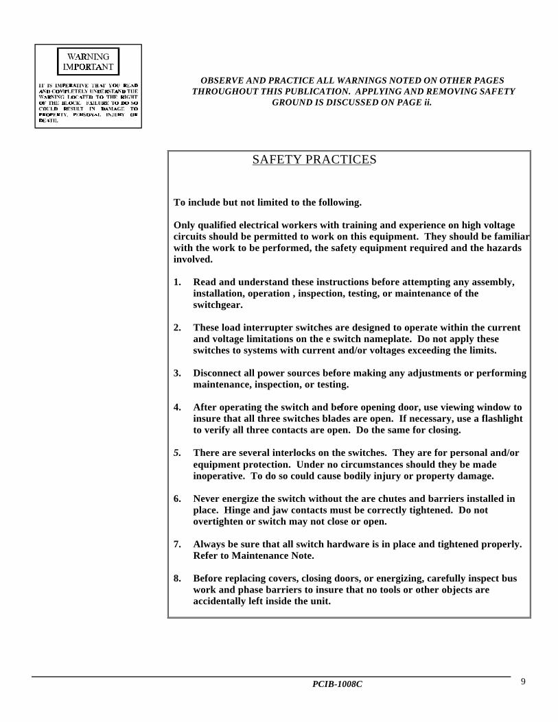
SAFETY PRACTICES
To include but not limited to the following.
Only qualified electrical workers with training and experience on high voltagecircuits should be permitted to work on this equipment. They should be familiarwith the work to be performed, the safety equipment required and the hazardsinvolved.
1. Read and understand these instructions before attempting any assembly,installation, operation , inspection, testing, or maintenance of theswitchgear.
2. These load interrupter switches are designed to operate within the currentand voltage limitations on the e switch nameplate. Do not apply theseswitches to systems with current and/or voltages exceeding the limits.
3. Disconnect all power sources before making any adjustments or performingmaintenance, inspection, or testing.
4. After operating the switch and before opening door, use viewing window toinsure that all three switches blades are open. If necessary, use a flashlightto verify all three contacts are open. Do the same for closing.
5. There are several interlocks on the switches. They are for personal and/orequipment protection. Under no circumstances should they be madeinoperative. To do so could cause bodily injury or property damage.
6. Never energize the switch without the are chutes and barriers installed inplace. Hinge and jaw contacts must be correctly tightened. Do notovertighten or switch may not close or open.
7. Always be sure that all switch hardware is in place and tightened properly.Refer to Maintenance Note.
8. Before replacing covers, closing doors, or energizing, carefully inspect buswork and phase barriers to insure that no tools or other objects areaccidentally left inside the unit.
PCIB-1008C 10
RECEIVING
Upon receipt of the load break interrupter switchgear,immediately make an examination for any damage or losssustained in shipment. This pertains the housing as well as theload break switch and mechanism. If injury, loss or roughhandling is evident, a written damage claim should be filed atonce with the transportation company and the PowerconCorporation should be notified at the same time. Be sure thatno loose parts are left in the packaging material. Vacuum outany dirt or loose particles of packing material on or around theload break switch mechanism. Study the erection drawingcarefully and check the bill of material to be sure that all partsare on hand.
STORAGE
When the unit is not to be placed in service immediately, itshould be stored in a clean, dry location and covered with asuitable cover. Moisture absorbing material should not beused to cover the equipment as that could cause corrosion ofparts. During the construction period it should be properlyprotected against construction environment conditions such asmoisture, dirt, cement, rough handling, abrasion or damage,etc.
When dampness or condensation exists, the equipment must becovered with a suitable vented cover to allow moisture toescape. Heaters of 250 watts rating should be placed in eachunit to prevent moisture damage. IF EQUIPMENT HASBEEN SUBJECTED TO MOISTURE IT SHOULD BETESTED WITH A 1000V MEGGER. A READING OF200 MEGOHMS SHOULD BE OBTAINED.
WARNING
REMOVE ALLFLAMMABLE
MATERIALS AWAYFROM HEATERS PRIOR
TO ENERGIZING
HANDLING
Prior to moving the equipment, please note possible problemsunder section PLAN YOUR INSTALLATION (page iii), whichmay arise due to improper handling. Equipment may be movedby a crane with slings. If a crane is not available, rollers may beused. Figure I shows suggested methods of handling theswitchgear.
INSTALLATION
ANSI C37.20.3 8.2.4 Installation
"Installation of MetalEnclosed InterrupterSwitchgear must only be donewith de-energized switchgear.When installing theswitchgear:(a) Protectworkers adequately from liveparts with barriers, screens,etc., (b) Observe NationalElectrical Safety Code ANSIC2,Rule 124 for guarding fiveparts."
ANSI C37.20.3 8.2.5 Removal of Shipping Members
"Before any installation of Metal Enclosed InterrupterSwitchgear a careful check should be made to insure thatall members included for shipping purposes, have beenremoved."
Switches are shipped closed to avoid shipping damage.Open switches in accordance with outlined instructions.
Before any installation work is done, consult and study alldrawings furnished by Powercon. These drawings includearrangement drawings, wiring and elementary diagrams and asummary of material.
Frequently, additional shipping members are installed in thebus and primary area to insure against shipping damage. It isimperative that all shipping members are removed, joints areproperly tightened and insulated before energizing bus.
Mats, screens , railings, etc., which are external to theswitchgear, but which may be required to meet any local codes,must be furnished by the purchaser.
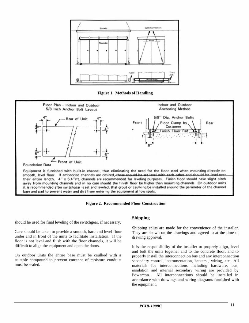
Preparation of Floor (Anchoring)
The station floor must be strong enough to prevent sagging dueto the weight of the switchgear structure. The impact loadingis approximately 1. I times the static load.
Suitable means must be provided by the purchaser foranchoring the equipment to the floor. It is essential that thefloor be level to avoid distortion of the switchgear structureand the equipment be completely aligned prior to the finalanchoring. The recommended floor construction is shown inFigure 2. The floor channels must be level and straight withrespect to each other. Steel shims
PCIB-1008C 11
Figure 1. Methods of Handling
Figure 2. Recommended Floor Construction
should he used for final leveling of the switchgear, if necessary.
Care should be taken to provide a smooth, hard and level floorunder and in front of the units to facilitate installation. If thefloor is not level and flush with the floor channels, it will bedifficult to align the equipment and open the doors.
On outdoor units the entire base must be caulked with asuitable compound to prevent entrance of moisture conduitsmust be sealed.
Shipping
Shipping splits are made for the convenience of the installer.They are shown on the drawings and agreed to at the time ofdrawing approval.
It is the responsibility of the installer to properly align, leveland bolt the units together and to the concrete floor, and toproperly install the interconnection bus and any interconnectionsecondary control, instrumentation, heaters , wiring, etc.. Allmaterials for interconnections including hardware, bus,insulation and internal secondary wiring are provided byPowercon. All interconnections should be installed inaccordance with drawings and wiring diagrams furnished withthe equipment.

PCIB-1008C 12
Interlocks
ANSI C37.20.3 8.5 Interlocks
"Interlocks should be checkedfor proper operation before isapplied to the switchgear.Check the access interlock tobe sure (1) that access to thepower fuses cannot beobtained unless the interrupterswitch is open, and (2) that theinterrupter switch cannot beclosed while the power fusesaccessible. In order tomaintain the integrity of keyinterlock systems, duplicatekeys should be destroyed orretained in a place accessibleonly to authorized personnel.”
WARNING
INTERLOCKS AREPROVIDED ON THIS
EQUIPMENT
WHEN KEY INTERLOCKSARE FURNISHED, OFTEN
DUPLICATE KEYS AREAVAILABLE. THESE ARE
FOR INSTALLATIONONLY. DUPLICATE KEYS
MUST BE DESTROYEDOR RETAINED IN A
PLACE ACCESSIBLE TOAUTHORIZED
PERSONNEL ONLY,BEFORE ANY PART OF
THE EQUIPMENT ISENERGIZED. FAILURE
TO DO SO ORDEFEATING ANY PART
OF THE KEY INTERLOCKSCHEME, CAN PROVIDE
ACCESS TO THEEQUIPMENT OR PERMIT
OPERATING ERRORS,WHICH CAN RESULT IN
PROPERTY DAMAGE,WHICH CAN RESULT IN
PROPERTY DAMAGE,INJURY OR DEATH.
Prior to operation, refer to sections entitled OPERATIONand MAINTENANCE of this manual. In addition, consultdrawings for proper operating sequence.
All Powercon Interrupter Switchgear is equipped with amechanical device that deters access to a closed switch with itsdoors open.
Heaters(Standard in Outdoor Equipment Only)
By maintaining a slight temperature differential, the heatershelp facilitate drying and prevent condensation and theresulting corrosion and insulation deterioration which mightoccur.
For heaters as supplied in the switchgear either external orinternal, sources of power must be supplied. With eithersource care must be taken to make sure of energizing prior tothe equipment being subjected to moisture. In all cases, thesupply must be adequate to feed the entire heater load.
CAUTION
SUPPLYING EXTERNALSOURCES OF CONTROL
POWER TO THISSWITCHGEAR MAY
CAUSE BACKFEED TOTHE HIGH VOLTAGE
BUS THROUGHCONTROL POWER OR
POTENTIALTRANSFORMERS. CARE
MUST BE TAKEN BYDISCONNECTING THE
BACKFEEDTRANSFORMERS ANDSAFELY GROUNDING
THE PRIMARIESBEFORE ENERGIZING
THE AUXILIARY POWER.REMOVE ALL GROUNDSPRIOR TO ENERGIZING
THIS EQUIPMENT.
PCIB-1008C 13
Connections
ANSI C37.20.3 8.2.6.1 Bus Connections
"When the Metal Enclosed Interrupter Switchgear consists ofseveral shipping sections, the main bus is necessarilydisconnected before shipping. The main bus should bereconnected with particular attention to the cleanliness of andpressure between the contact surfaces. It is essential that theconnections be securely bolted because the conductivity of thejoints is dependent on the applied pressure. Refer tomanufacturer's torque instructions and any other specialinstructions." (Reference Table 2)
ANSI C37.20.3 8.2.6.2 Cable Connections
"Before making up the cable connections, the phasing ofeach cable should be determined in accordance with theconnection diagram, and the cables tagged accordingly.The cable manufacturer's instructions should be followedwhen forming cable terminations and during the installationof the cable. It is essential that the connections be cleanand securely bolted, since the conductivity of the joints isproportional to the applied pressure. The terminatingdevices (where required) should be installed pursuant to theterminator manufacturer's instructions."
ANSI C37.20.3 8.2.6.3 Control Connections
"Control wires between shipping sections should bereconnected as marked by the manufacturer. Connectionswhich are to be connected to the terminals in apparatusremote from the switchgear should be carefully checkedagainst the connection diagram. When making connectionsto terminals, care should be exercised to assure that theconnections are properly made."
The main bus bars and other connection bars may be eithercopper or aluminum. In either case, the connection surfaceswill be made of silver surfaced or equivalent. All fieldassembled joints in primary conductors, regardless of materialor method of insulation, should be made as described below:
(1). Wipe silver clean. Do not use sandpaper or anyabrasive on the silvered surface. Avoid handling ofcleaned surface as much as possible.
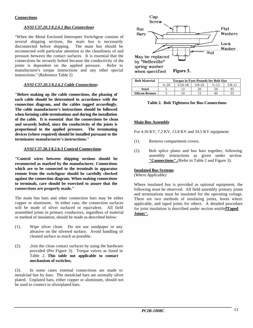
(2). .Join the clean contact surfaces by using the hardwareprovided (Per Figure 3). Torque valves as listed inTable 2. This table not applicable to contactmechanism of switches.
(3). In some cases external connections are made tometalclad bus by bars. The metalclad bars are normally silverplated. Unplated bars, either copper or aluminum, should notbe used to connect to silverplated bars.
Bolt Material Torque in Foot-Pounds for Bolt Size¼-20 5/16-18 3/8-16 ½-13 5/8-11
Steel 5 12 20 50 95Silicon Bronze 5 10 15 40 55
Table 2. Bolt Tightness for Bus Connections
Main Bus Assembly
For 4.16 KV, 7.2 KV, 13.8 KV and 34.5 KV equipment:
(1). Remove compartment covers.
(2). Bolt splice plates and bus bars together, followingassembly instructions as given under section"Connections". (Refer to Table 2 and Figure 3).
Insulated Bus Systems(Where Applicable)
Where insulated bus is provided as optional equipment, thefollowing must be observed. All field assembly primary jointsand terminations must be insulated for the operating voltage.There are two methods of insulating joints, boots whereapplicable, and taped joints for others. A detailed procedurefor joint insulation is described under section entitled "TapedJoints".
PCIB-1008C 14
World Wide Service
Conveniently located on the east coast between Baltimore andWashington, Powercon’s facility is only hours away from
Philadelphia and New York. In addition to its proximity to thenation’s great industrial centers, Powercon reaches international
markets through the ports and air terminals of the easternseaboard.
POWERCON FIELD SERVICE ENGINEERING
Powercon’s 24-hour a day field service is provided though factory FieldService Engineers. Our Field Service Engineers are highly skilledSWITCHGEAR experts extremely proficient in providing the highestquality service for switchgear and its components.
Our Service Engineering Group is in close liaison with other Powerconengineers who create the applications, and the mechanical and electricaldesign of each switchgear equipment. Powercon also maintains detailedrecords of every part and component manufactured and/or purchased foreach project. They have immediate access to the purchasing staff forsuppliers service.
Powercon is prepared to provide you with:Emergency ServiceInstallation Supervision of New EquipmentCoordination Check of New EquipmentOther Required Installation and Engineering ServicesRepair and Maintenance Service for Existing or Obsolete EquipmentAdvice and Instruction of Preventive Maintenance ProceduresIn Warranty Service
PCIB-1008C 15
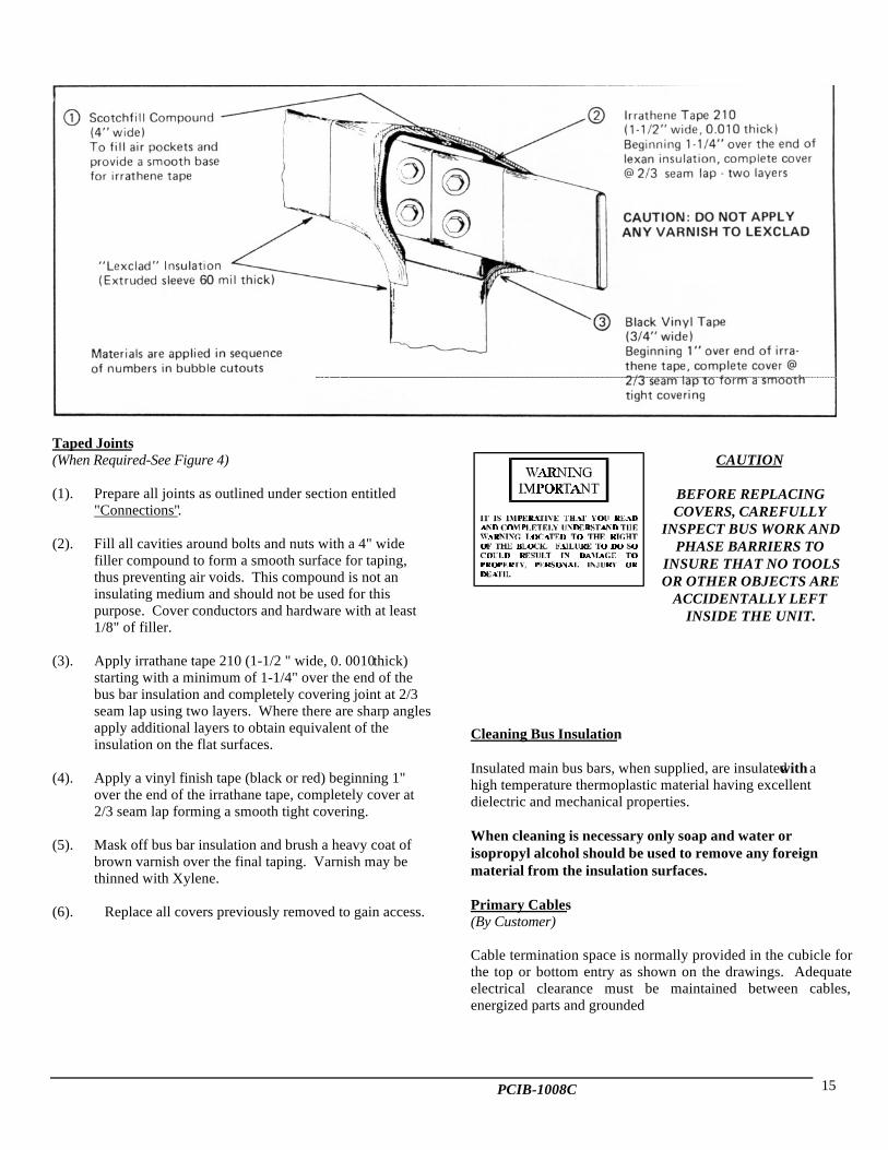
Taped Joints(When Required-See Figure 4)
(1). Prepare all joints as outlined under section entitled"Connections".
(2). Fill all cavities around bolts and nuts with a 4" widefiller compound to form a smooth surface for taping,thus preventing air voids. This compound is not aninsulating medium and should not be used for thispurpose. Cover conductors and hardware with at least1/8" of filler.
(3). Apply irrathane tape 210 (1-1/2 " wide, 0. 0010 thick)starting with a minimum of 1-1/4" over the end of thebus bar insulation and completely covering joint at 2/3seam lap using two layers. Where there are sharp anglesapply additional layers to obtain equivalent of theinsulation on the flat surfaces.
(4). Apply a vinyl finish tape (black or red) beginning 1"over the end of the irrathane tape, completely cover at2/3 seam lap forming a smooth tight covering.
(5). Mask off bus bar insulation and brush a heavy coat ofbrown varnish over the final taping. Varnish may bethinned with Xylene.
(6). Replace all covers previously removed to gain access.
CAUTION
BEFORE REPLACINGCOVERS, CAREFULLY
INSPECT BUS WORK ANDPHASE BARRIERS TO
INSURE THAT NO TOOLSOR OTHER OBJECTS ARE
ACCIDENTALLY LEFTINSIDE THE UNIT.
Cleaning Bus Insulation
Insulated main bus bars, when supplied, are insulated with ahigh temperature thermoplastic material having excellentdielectric and mechanical properties.
When cleaning is necessary only soap and water orisopropyl alcohol should be used to remove any foreignmaterial from the insulation surfaces.
Primary Cables(By Customer)
Cable termination space is normally provided in the cubicle forthe top or bottom entry as shown on the drawings. Adequateelectrical clearance must be maintained between cables,energized parts and grounded
PCIB-1008C 16
metal parts. It is also the installer's responsibility toadequately support cables such that insulators or bus bars donot carry the strain of the cables.
Before any primary cable connections are made, the cablesshould be identified to indicate their phase relationship withthe switchgear connections. This is necessary to insure thatmotors will rotate in the proper direction and that the phaserotation is the same when interconnecting two differentsources of power.
Non-shielded portions of cable must be fully insulated fromground and any associated devices such as window CT's.Refer to proper cable and/or termination manufacturer'sinstructions to make this installation.
Lightning Protection
It will be the responsibility of the purchaser to providesuitable lightning arrestors to protect the switchgear fromdamage due to lightning.
Door Alignment
If for any reason it becomes necessary to realign the doors ofthe switchgear during installation, follow the proceduresgiven in the following paragraphs.
After checking that the switchgear is level and plumb asdescribed previously under section entitled, "Preparation ofFloor (Anchoring)" , start at either end of the switchgearline-up and realign each door individually as required.
The top of each door should be level with the adjacent doorsand the space between adjacent doors equalized to permittheir free swing. Doors should present an overall neatappearance. 'Me doors stops should be adjusted to permit adoor swing of approximately 105 degrees.
Doors may be raised or lowered vertically, or moved left orright horizontally by loosening the hinge mounting nuts andshifting the hinge and door assembly as allowed by the slottedholes in the hinge.
Doors may be shifted to the forward or backward by addingor removing the washers or shims from between the hingeand the side sheets.
When properly aligned, the doors of outdoor switchgear shouldbe tightly sealed on the gasket all around. After aligning suchdoors, close and latch the door and check the seal with a 3" x 5"card, shipping tag, IBM card or similar card, around the edge ofthe door. If the card will pass between the door and gasket, thedoor is improperly adjusted and should be re-adjusted until thecard will no longer pass through.
Fuses
CAUTION
Fuses when supplied byPowercon are not installed
when shipped. They must heinstalled in the final
installation. The installermust verify that all fuses,holders, etc. are securelyplaced in their stationary
live parts and wherelatching or locking
accommodations areprovided, that fuses arelatched and/or locked in
place It is the responsibilityof the installer to properly
install fuses, holders,fittings, etc. Fusing mustnot be done on energized
equipment.
See "MAINTENANCE" section for re-fusing instructions.Since there is such a wide variety of fuses available, refer toproper fuse instruction book for detailed assembly andinstallation instructions.
Ground Bus
The ground bus is bolted to the frame near the bottom. It isarranged so that connectors to the station ground can be madein any unit. Where the equipment is shipped in more than onegroup, the sections of the ground bus must be connected byusing splice plates furnished with the equipment. Assemblejoints as outlined under "Connections" . Ground busconnections are made in the lower portion of the cable entrancecompartment. The switchgear ground bus must be connectedto the station ground bus by a conductor having a currentcarrying capacity equal to that of the switchgear ground bus. Itis very important that the equipment be adequately grounded toprotect the operator from injury when short circuits or otherabnormal occurrences take place and to insure that all parts ofthe equipment, other than live parts, are at grounded potential.
PCIB-1008C 17
PRE-OPERATIONAL INSPECTIONAND TESTING
(See Check List on Back Cover)
ANSI C37.20.2 8.3 Pre-Operational Check
"Care must be exercised to prevent the Metal EnclosedInterrupter Switchgear from being energized from thepower system while preliminary tests are being conducted.If disconnecting means are not available, line leads shouldbe disconnected. All internal connections should beexamined to insure that they have not been loosened ordamaged during shipment or installation and all boltedconnections and joints should be tightened in accordancewith manufacturer's instructions. All wiring connectionsshould be checked for tightness, including those atinstrument transformers and all terminal blocks. Removecurrent transformer shorting devices on all active circuits.It is recommended that the integrity of control buses bechecked with an ohm meter to insure against short circuitsin the control wiring. Control wiring should be given a highpotential test or be insulation resistance tested. Powercircuits, such as buses and interrupter switches, shouldreceive a low frequency withstand test as described insections 5.1 and 5.5. After the Metal Enclosed InterrupterSwitchgear has been installed and all interconnectioncompleted, any control schemes should be operationallytested and power connections given a final check for phaserotation/sequence before the switchgear is finally energizedfor service."
CAUTION
INSTRUCTIONS ANDSAFETY
PRECAUTIONS LISTEDTHROUGHOUT THISPUBLICATION MUST
BE STRICTLYOBSERVED.
OPERATE AT LEAST 15OPEN/CLOSE
OPERATIONS ANDOBSERVE PROPER
PERFORMANCE PRIORTO ENERGIZATION
After the equipment has been installed and allconnections made, it should be tested and inspectedbefore being put
in service. Check area for foreign materials, tools, etc.that may have been placed on or near high voltage parts.Vacuum floors free of debris, wipe and clean down allbarriers, bus insulators, bushings, switches, etc. with adenatured or isopropyl alcohol. Wipe with a clean drycloth. Although the equipment and devices have beencompletely tested at the factory, a final field test shouldbe made to be sure that the equipment has been properlyinstalled and that all connections are correct and havenot become loosened in transportation.
THE PRIMARY EQUIPMENT SHOULD BECOMPLETELY DE-ENERGIZED WHILE THE
TESTS ARE IN PROGRESS
Directions for testing devices such as relays, and metersare given in the manufacturer's instruction bookfurnished for each device. Special instruction books arefurnished for complicated automatic equipmentsdescribing operating sequences for each.
When transformers are furnished to supply the controlpower, the primary taps should be selected so that thecontrol voltage indicated on the wiring diagram isobtained on the secondary of the transformer. When abattery is used to supply the control power, the cablesfrom the battery to the switchgear should be largeenough to avoid excessive voltage drop.
High potential tests to check the integrity of theinsulation are not necessary if the installationinstructions in this book are carefully followed. If thepurchaser wishes to make high potential tests, thevoltage should not exceed 75% of the IEEE factory testvoltages.
Potential, current, and control power transformers mustbe disconnected during high voltage tests.
OPERATION
Description
The powerful opening and closing springs ofPowercon's off-center stored energy mechanismprovides for quick make (rated fault closing) and quickbreak (rated load interruption). 'The switch mechanismshaft is driven by a chain and sprocket from the frontoperating handle. As the handle is rotated, it is directlyconnected to a sprocket which in turn chain drives theopening spring to a "charged" position . As the operatorcontinues to rotate the handle, the charged spring isdriven off-center by the
PCIB-1008C 18
chain and releases its energy into rotating the operatingshaft to open. The switch blades will not move, ineither a closing or opening direction, until the closingspring causes rotation in the operating shaft. It should benoted that once the springs are moved off-center, the operatorhas no further control of the opening and closingoperation. He therefore has a fault closing and ratedload break feature independent of his performance.
SEQUENCE OF OPERATION
(Quick Make-Rated Fault Close) (Quick Break-Rated Load Interruption)
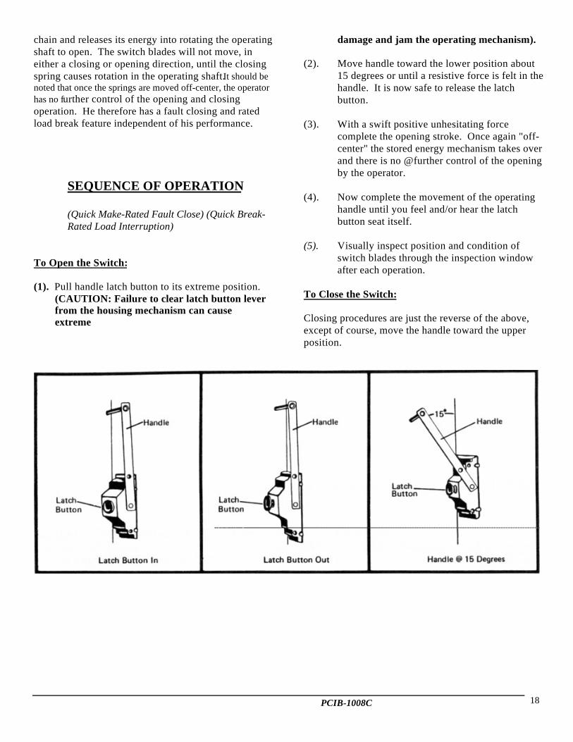
To Open the Switch:
(1). Pull handle latch button to its extreme position.(CAUTION: Failure to clear latch button leverfrom the housing mechanism can causeextreme
damage and jam the operating mechanism).
(2). Move handle toward the lower position about15 degrees or until a resistive force is felt in thehandle. It is now safe to release the latchbutton.
(3). With a swift positive unhesitating forcecomplete the opening stroke. Once again "off-center" the stored energy mechanism takes overand there is no @further control of the openingby the operator.
(4). Now complete the movement of the operatinghandle until you feel and/or hear the latchbutton seat itself.
(5). Visually inspect position and condition ofswitch blades through the inspection windowafter each operation.
To Close the Switch:
Closing procedures are just the reverse of the above,except of course, move the handle toward the upperposition.
PCIB-1008C 19
MAINTENANCE
CAUTION
Before any checking or maintenance of the switchgear after it hasbeen installed, the following must be observed.- Only qualified persons
may operate, inspect or maintain power switchgear. In addition topersonnel, you may have that are qualified, others may be availablefrom an experienced High-Voltage contractor or the utility servicingthe installation. It is the responsibility of the purchaser, installer. or
ultimate user to insure that the warning voltage signs are notremoved. Make sure all access doors and opening handles are
securely locked when the gear is left unattended by qualified peopleeven momentarily
DANGER
HAZARDOUS VOLTAGEDO NOT REMOVE COVERS OR OPEN DOORS OR WORK ON EQUIPMENT
UNLESS POWER HAS BEEN TURNED OFF AND ALL CIRCUITS DE-ENERGIZED AND DISCONNECTED
DISCONNECT, DE-ENERGIZE, LOCK-OUT AND PROPERLY GROUNDCIRCUITS(S) BEFORE WORKING ON THE EQUIPMENT.
USE PROPER SAFETY PRECAUTIONS WHEN WORKING ON THISEQUIPMENT.
CAUTION
CONSIDER THIS EQUIPMENT ALIVE UNTIL ALL SOURCES OF VOLTAGEARE REMOVED AND SAFELY GROUNDED
MAKE A LIST OF ALL TOOLS, WIPE CLOTHS, ETC. USED IN THEMAINTENANCE PROCESS. AFTER WORK IS COMPLETE CHECK TO MAKE
SURE NOTHING IS LEFT IN THE SWITCHGEAR.
TRAINING
ORDER TRAINING TAPES TP002, PARTS 1, 2, AND 3 FOR SAFETY, OPERATION, AND MAINTENANCE
Disconnect, and remove this switchgear from all sourcesof electric power, so that it is COMPLETELY de-energized prior to working on it. This includes but isnot limited to:
I . The switchgear supply source of electricity.
2. Back feed of electricity from:
a. Motorsb. Generatorsc. Power transformers
d. Potential transformerse. Control power transformersf. Other sources of electrical powerg. Outgoing and/or incoming distribution systemh. Paralleled sources

PCIB-1008C 20
FOLLOW SEQUENCE OF OPERATION OF THE PRECEDING PAGE BEFORE DOINGANY OF THE FOLLOWING:
1. Periodic Checking
Load break switches should be examined and checkedonce a year or sooner when conditions require it (such asnumerous operations, polluted atmosphere oroverloading of the switch). All switches shouldoccasionally be opened and closed several times insuccession, not exceeding their rated duty.
2. Cleaning
All switches, including insulators and operating armsshould be thoroughly cleaned periodically by wiping witha clean cloth to prevent accumulations of dust. Aftercleaning, a light coat of lubricant (non-corrosive, high-temperature grease) should be applied to the contactsurfaces. Do not use "cup" or other grease which mayharden upon exposure to air.
3. Contacts
Check to determine that the blades make good contact.IMPORTANT. THIS IS A SLIDING JOINT. Overtightening can cause the switch not to open and alsocause severe damage to the mechanism. A contactresistance reading between line and load terminal padsshould be taken and should be taken and should bebetween 35 to 80 micro-ohms. If values are less than 35micro-ohms, insure that the blades can be "opened" fromjaw casting with a pulling force of approximately 30-35pounds measured at a point between the main blades justbelow the jaw contact.
Switches are provided with silver to silver contacts.These contacts do not tarnish like copper, but they shouldbe "wiped" clean occasionally, especially if the switch hasnot been operated for some time. This
can be done by opening and closing the switch severaltimes in succession. DO NOT ATTEMPT TO GRINDTHE BLADES WITH POWERED EMERY OROTHER ABRASIVES. Such practice inevitably resultsin poor contact and overheating.
See "INSTALLATION" for aligning and make propercontact.
4. Insulators and Barriers
It is necessary that insulator surfaces be kept clean. Thisis absolutely essential, particularly when the switches arelocated where cement dust, metallic dust, salt spray, acidfumes and other unfavorable environmental conditionsexist. Alcohol cleaner or a light detergent isrecommended for cleaning the porcelain insulators.
5. Insulation Check
When making an annual check, all insulation should becarefully examined for tracking. Special attention mustbe given to areas where the conductor passes through aninsulator or lays near a barrier. Examine the surface forcracks or streaked discoloration. When tracking is foundthe insulation involved must be replaced.
6. Bus and Conductor (Switch Blade) Check
Inspect the bus and connections carefully every year forevidence of overheating. It is desirable to measure theresistance to ground with a meter (or use a megger ofproper voltage) and between phases of the insulation ofbus and connections. A record should be kept of thisreading. Weakening of the insulation from onemaintenance period to the next period can be recognizedfrom the recorded readings. At recording time, the recordshould include the temperature, the humidity, and thedate.
7. Chain Drive
The chain drive assembly connects the stored energymechanism to the operating handle on the front of thehousing. It consists of a length of roller type chainfastened in a loop by two turnbuckles with locking nuts.All chain assemblies are factory adjusted.
8. Operating Shaft
The operating shaft connects the stored energymechanism to the switch operating arms. The shaft

PCIB-1008C 21
is integral with the switch assembly and is bearingmounted. Light lubricant applied to bearing surfaceswill insure trouble free operation. No adjustments arenecessary.
9. Pushrods
Each main blade of the switch is connected to the throwarms or the main operating shaft by an insulatingpushrod. These rods should be examined during eachnormal maintenance procedure for signs of damage toeither end of the pushrods. If a damaged pushrod isencountered, replacement parts may be obtained byreferring to the "Ordering of Spare Parts" section of thismanual.
10. Stored Energy Mechanism
The stored energy mechanism consists of a housing witha one piece crank sprocket assembly supported bybearings and a spring assembly.
The sprocket assembly is chain driven by means of ahandle on the front of the housing. As the handle ismoved upward, the spring assembly is charged. As thecrank sprocket assembly passes over dead center, thespring takes over and instantaneously moves the switchto the closed position. The unit is factory adjusted andshould need no adjustment in the field. The onlymoving parts which should be checked afterapproximately 100 operations are the front and rearlatches, which are spring operated, and the (2) shaftbearings. Check to make sure the latches rotate freelyup and down by using finger pressure on the rollers.
11. Lubrication
The load break interrupter switch requires infrequentlubrication, Bearing points and sliding surfaces shouldbe lubricated at the regular inspection periods with athin film of lubricant. Before lubrication, remove anyhardened grease and dirt from latch and bearing surfaceswith kerosene. All lubrication should be done with lowtemperature grease. Mobile SHC 32 Product Doe640214 is recommended.
12. High Potential Tests
High potential tests to check the integrity of theinsulation are not necessary if the insulationmaintenance instructions in this book are carefullyfollowed. Should the purchaser desire to make highpotential tests, the test voltage should not exceed 14KVAC for 4.16 kV, 27 KVAC for 13.8 kV and 60KVAC for 34.5 kV equipments. These voltages are75% of factory test voltages and are in accordance withANSI standards.
13. Bus Section
a. Remove covers. Check buses and connections forevidence of overheating or weakening of theinsulation.
b. Check that all bus mounting bolts and spliceconnection bolts are tight and torque if required.
c. After cleaning, megger and record the resistance toground and between phases of the insulation ofbuses and connections. Since definite limitscannot be given for satisfactory insulationresistance values, a record should be kept of thereading. Weakening of the insulation from onemaintenance period to the next can be recognizedfrom the recorded readings. The reading should betaken under similar conditions each time and therecord should include temperature and humidity.
14. Cable and Bus Duct Terminals
Inspect all main cable connections for signs of overheating andwhen possible check that connections are tight and torque ifrequired.
15. Overall Switchgear
a. Check that all secondary control wiringconnections are tight. Check continuity.
b. Check to see that all anchor bolts and bolts in thestructure are tight.
c. If the switchgear is equipped with heaters, check tosee that all heaters are energized and operating.
d. Check the ground bus connection and mountingbolts for tightness. Clean the ground bus.
e. Clean and inspect all painted surfaces. Retouchwhere necessary.
f. Check for strange items such as tools, loose nutsand bolts, etc. that are not normally part of theequipment.
g. Indications of moisture:(1) Staining(2) Tracking over insulators(3) Rust(4) Paint crazing or bubbles
PCIB-1008C 22
h. Indications of partial discharge (corona):(1) Ozone odors(2) Tracking of bus supports and insulators(3) Crackling or sparking noises(4) Components glowing in the dark
i. Check for cleanliness
j. Check for indications of overheating:
(1) Cracked or crazed insulation(2) Discolored bus insulation, paint, etc.
k. Check caulking of bottom (See Page 5)
RE-FUSING
Precautions
See "MAINTENANCE", Page 14.
RE-FUSING OF High-Voltage SWITCHGEARSHOULD BE PERFORMED ONLY BY
QUALIFIED PERSONS, OBSERVING THEFOLLOWING PRECAUTIONS. THESE
RECOMMENDATIONS MAY DIFFER FROMSTANDARD OPERATING PROCEDURES AND
SAFETY PRACTICES OR CERTAINELECTRIC UTILITY COMPANIES. WHERE
SUCH DISCREPANCY EXISTS, THEELECTRIC UTILITIES SHOULD FOLLOW
THEIR OPERATING PROCEDURES.
1. Adhere to prescribed safety rules at all times.
2. Wear approved and periodically tested rubbergloves, hard hat, safety glasses and flashclothing.
3. Perform operations only in the presence ofother qualified persons.
4. Always assume both sets of terminals areenergized unless proved otherwise by bothvisual evidence of open circuit and bygrounding.
5. Always have appropriate tools and equipmentavailable.
Preparatory Procedures
Open the switch associated with the affected fuse(s).Then open the switchgear door to gain access to thefuses. Check backfeed - See Page 14.For actual re-fusing, see applicable instruction for fusesand manufacturers recommended practices andprocedures.
PAINT TOUCH-UP
( If further information is required - refer to thePowercon Corporation.)
A. Sand marred or scraped area with fine sandpaper(No. 400).
B. Make certain area is clean and free of grease or oil.
C. Apply two coats of all purpose primer with a flatbrush or small spray gun.
D. Feather paint into unmarred portion with lightstrokes of the brush or light passes with the spraygun.
E. When primer has dried, apply two coats of finishpaint in the same manner.
F. Small narrow scratches may be best covered byusing an artist's brush to fill in the scratched area.
G. If time allows, give the primer additional dryingtime and sand between coats.

PCIB-1008C 23
ORDERING SPARE PARTS
The following table is provided as a reference guide to stocking levels of spare parts to minimize downtime when used with aconscientiously applied maintenance program.
RECOMMENDED STOCK FOR FIVE 3-POLE SWITCHES
Catalog Number Name of Part QuantityS-4449-27 Arc Chute Assembly, 5kV and 15kV 3B-1459 Arc Chute Assembly, 34.5kV 3S-4449-18 Quick Break Auxiliary Blade, 5kV and 15kV 3A-29715 Quick Break Auxiliary Blade, 34.5kV 3S-4449-22 Hinge Casting (600A), 5kV and 15kV NoneS-4107-22 Hinge Casting, 34.5kV NoneS-4449-21, 21A Jaw Casting, 4kV and 15kV NoneS-4107-23 Jaw Casting, 34.5kV NoneS-22867, 22868 Main Blades, 600A, 5kV and 15kV 6 (3 Each)S-22869, 22870 Main Blades, 1200A, 5kV and 15kV 6 (3 Each)B-1460 Main Blade Assembly, 34.5kV 6 (3 Each)S-4449-42 Front Connected Insulator, A20, 15kV 4S-4449-43 Front Connected Insulator, A20, 5kV 4S-4107-1 Porcelain Insulator, B40, 34.5kV 3Shop Order No. Barrier, 5kV, 15kV, and 34.5kV 1 Set (4)Shop Order No. Barrier Spacer, 5kV, 15kV, and 34.5kV 1 Set (4)S-4440-37, 39 Insulating Link Assembly (Pushrods), 5kV and 15kV 1 Set (3)A-29726 Insulating Link Assembly (Pushrods), 34.5kV 1 Set (3)

PCIB-1008C 24
TROUBLE SHOOTING (OVERHEATING)
The following table show remedies for correcting overheating problems.
TROUBLE SHOOTING CHART
HIGH VOLTAGE FUSES AND DISCONNECTING SWITCHESTrouble Cause Remedy
Overload
If the switch is overhearing because ofexcess current, one of tow remediescan be adopted: Replace with a switchof rating adequate for the present orfuture loads, or Rearrange circuits toremove excess load.
Poor Contact(Contact out of Alignment)
Adjust Contacts
Connections to Switch not AdequateCurrent-Carrying Capacity
Increase the capacity of theconnections by adding conductors orby replacing with heavier conductors
OVERHEATINGContact Burned or Pitted Contacts should be dressed and fitted
properly.
Bolts & Nuts of Connections not Tight
Tighten all bolts and nuts. (Too muchpressure must not be used intightening nuts on bolts. Use of toolarge a wrench may cause excessivepressure that the expansion of thebolts exceeds their elastic limit,leading to more loosening of theconnection).
Located in Too Hot an Ambient.(Such as too close to a boiler, afurnace, or the like).
Relocate in a cooler place or arrangesome means of cooling.
PCIB-1008C 25
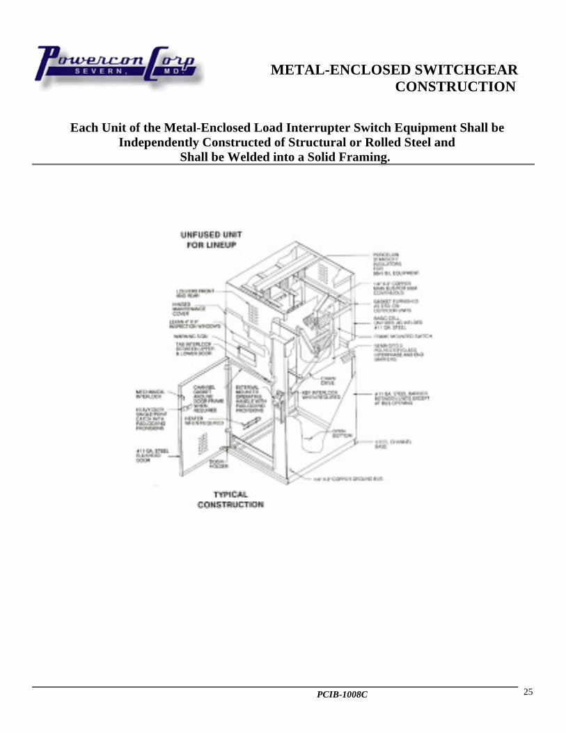
METAL-ENCLOSED SWITCHGEARCONSTRUCTION
Each Unit of the Metal-Enclosed Load Interrupter Switch Equipment Shall beIndependently Constructed of Structural or Rolled Steel and
Shall be Welded into a Solid Framing.

PCIB-1008C 26
1551 FLORIDA AVENUE SEVERN, MARYLAND 21144410-551-6500
email: [email protected]://www.powerconcorp.com
INSTRUCTION TAPE - VHSCAT#TP002
METAL ENCLOSED 5kV Thru 38kVLOAD BREAK INTERRUPTER SWITCHGEAR
To be used in conjunction with Instruction Books:PCIB-1008B, PCIB-1002
with Instruction Information On:Receiving Inspection *Testing * Operation * Maintenance*Adjustments
Including:Partial Safety Practices
InterlocksConnections
Electric OperatorsGeneral Construction
Bolt TorquingDemonstrations
Slow Motion Demonstration with 1100 Frame/Sec of Switch Operations
Net Price................................................................................................................... $375.00

PCIB-1008C 27
LOAD BREAK INTERRUPTER SWITCHGEAR CHECK LIST FORPRE-OPERATIONAL, INSPECTION, TESTING, AND MAINTENANCE
CUSTOMERSWITCHGEAR IDENTIFICATIONLOCATION OR JOB NAMEAPPROVED FOR OPERATION BY
A. SWITCH BLADES AND ARC BLADES
⇒ Check arc blade alignments with arc chutes and stationary arcingcontacts.
⇒ Check arc blade clearance with arc contacts⇒ Inspect switch blade end for silver contacts⇒ Check switch blade alignment with jaw casting contact.⇒ Check switch blade torque at hinge casting contact.⇒ Insure contact grease is on casting contacts.⇒ Check for proper alignment of switch assembly in cubicle.⇒ Check Visually for 15 Operators
B. INSULATORS
⇒ Inspect pushrods for defect⇒ Insure cotter pin fasteners are spread apart (when applicable)⇒ Check switch blade alignment with levers on shaft Check length
of eye bolt within insulating rod (when applicable) Inspectinsulators for defects or dirt
⇒ Insure lightning arrestors are mounted securely (when furnished)Check for tightness of nut on insulator rods (when furnished)
C. HANDLE MECHANISM
⇒ Check Chain on mechanism for proper tension⇒ Check handle release knob for freedom of movement⇒ Check handle positioning top and bottom of casting⇒ Check handle unit for (3) nameplates⇒ Inspect adjusting rods for proper length within adjusting bolt
(when applicable)
D. CABLE AND BUS
Inspect bolts on bus connections for tightness⇒ Check clearance phase to phase and phase to ground of cable
and bus⇒ Bus and cable supports are adequate⇒ Inspect cables for penciling at ends⇒ Inspect cable termination in cable lugs for tightness⇒ Inspect placement of phase markings⇒ Check plating on bus bars⇒ Inspect taped joints for tightness (when applicable)⇒ Check connections on lugs⇒ Inspect taped joints for coverage of insulating varnish and
heating.
E. KEY INTERLOCKS (When applicable)
⇒ Check door block for lubrication⇒ Check key interlock system for proper sequence and operation⇒ Insure interlock is free from binding⇒ Check weathercap fits securely (outdoor only)⇒ Insure key nameplate matches key number⇒ Handle stops on casting do not interfere with interlock
mechanism. Remove all spare keys
F. FUSE ACCESSORIES
⇒ Check contact of fuses mounted in fuse clip⇒ Inspect unit for spare fuse holder or mounting⇒ Check alignment of fuses with fuse clips
G. SWITCH UNIT - GENERAL
⇒ Inspect phase barriers for secure mounting⇒ Check unit for manufacturers and nomenclature nameplates
Inspect paint' coverage of unit⇒ Inspect door handles, locking bars and mechanism and lubricate
Inspect for damaged, bent or twisted doors⇒ Check unit for proper device markings⇒ Inspect unit for gasketed joints (outdoor only)⇒ Check unit for water tightness, dirt, moisture, rust⇒ Inspect unit for door stop alignment (when applicable)⇒ Inspect unit doors for proper opening⇒ Check louvers for proper back up and clean filters.⇒ Seal all openings to prevent moisture, vermin, rodents, snakes,
etc. from entrance to equipment⇒ Check insulator for heat⇒ Check and torque all bolts⇒ Check heaters, thermostats and other environmental controls
H. MEGGER @ _____ VOLTS______ OHMS______
I. HI POT (75% of Factory)
J. REMARKS⇒ ____________________________________⇒ ____________________________________⇒ ____________________________________
1551 FLORIDA AVENUE SEVERN, MARYLAND 21144410-551-6500
email: [email protected]://www.powerconcorp.com