metal mems tools for beating-heart tissue removal
TRANSCRIPT
Metal MEMS Tools for Beating-heart Tissue Removal
Andrew H. Gosline, Member, IEEE, Nikolay V. Vasilyev, Arun Veeramani, MingTing Wu, Greg Schmitz,Rich Chen, Veaceslav Arabagi, Member, IEEE, Pedro J. del Nido and Pierre E. Dupont, Fellow, IEEE
Abstract— A novel robotic tool is proposed to enable thesurgical removal of tissue from inside the beating heart. Thetool is manufactured using a unique metal MEMS processthat provides the means to fabricate fully assembled devicesthat incorporate micron-scale features in a millimeter scaletool. The tool is integrated with a steerable curved concentrictube robot that can enter the heart through the vasculature.Incorporating both irrigation and aspiration, the tissue removalsystem is capable of extracting substantial amounts of tissueunder teleoperated control by first morselizing it and thentransporting the debris out of the heart through the lumenof the robot. Tool design and robotic integration are describedand ex vivo experimental results are presented.
I. INTRODUCTION
Surgical robotic systems are gaining popularity in clinicalpractice due to benefits such as motion scaling, tremorcancellation, enhanced or augmented displays, improveddexterity, and improved access to the surgical site. Often, andperhaps most significantly, the goal of these surgical robotsis to convert procedures that are typically done in an openfashion to a minimally invasive fashion. In the specific caseof cardiac procedures performed inside the heart, minimallyinvasive surgery eliminates the need to cut open the chest(sternotomy). More importantly, if these procedures can beperformed while the heart is beating (avoiding cardiopul-monary bypass), there is substantial benefit to the patient interms of reduced neurological risks.
While the introduction of catheters has transformed thetreatment of simple repairs by enabling beating-heart accessthrough the vasculature, many procedures remain possibleonly by open surgery on the stopped heart. There are severalreasons for this. Despite recent advances in catheter tech-nology [1], [2], [3], [4], [5], they can neither apply enoughforce to the tissue, nor be positioned accurately enough forcomplex surgical repairs.
Furthermore, appropriate tools do not exist for performingthe surgical tasks of tissue removal and tissue approximationinside the beating heart. While for many applications, itis possible to develop robots that use existing surgicaltools to perform procedures in a manner comparable tomanual surgery techniques, such as bronchial endoscopy [6]
This work was supported by the National Institutes of Health under grantsR01HL073647 and R01HL087797.
A. Gosline, N. Vasilyev, V. Arabagi, P. del Nido, P. Dupont arewith Cardiovascular Surgery, Children’s Hospital Boston, HarvardMedical School, Boston, MA, 02115, USA. {Andrew.Gosline,Nikolay.Vasilyev, Veaceslav.Arabagi, Pedro.DelNido,Pierre.Dupont}@childrens.harvard.edu
A. Veeramani, M. Wu, G. Schmitz and R. Chen are with MicrofabricaInc., Van Nuys, CA, USA
and laparoscopy [7], the environment of the beating-heartprecludes this approach. First, the chambers of the heartare too small to perform complex manipulations of tools.Secondly, tool manipulations cannot interfere with operationof the heart, for example, by occluding blood flow or byinducing arrhythmias. Thirdly, the procedure is performedin the bloodstream where high magnitude and varying flowvelocities make tool control and visualization difficult.
Prior work by our group has considered the design of arobotically-delivered tissue approximation device for percu-taneous beating-heart closure of a PFO [8]. The device hasbeen recently validated with in vivo porcine experiments.This work provided a novel alternative to both catheter-delivered occlusion devices and to surgical closure by suture.
This paper considers the task of tissue removal insidethe beating heart. In contrast to tissue approximation, nocatheter-based alternative to open surgery is available forremoving tissue inside the heart. Tissue removal is an im-portant component of many intracardiac procedures and isapplicable to both the pediatric and adult populations.
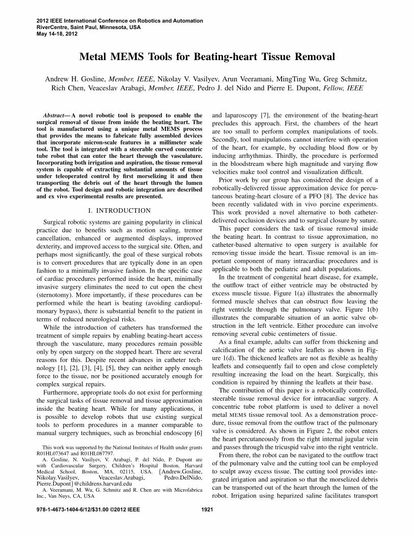
In the treatment of congenital heart disease, for example,the outflow tract of either ventricle may be obstructed byexcess muscle tissue. Figure 1(a) illustrates the abnormallyformed muscle shelves that can obstruct flow leaving theright ventricle through the pulmonary valve. Figure 1(b)illustrates the comparable situation of an aortic valve ob-struction in the left ventricle. Either procedure can involveremoving several cubic centimeters of tissue.
As a final example, adults can suffer from thickening andcalcification of the aortic valve leaflets as shown in Fig-ure 1(d). The thickened leaflets are not as flexible as healthyleaflets and consequently fail to open and close completelyresulting increasing the load on the heart. Surgically, thiscondition is repaired by thinning the leaflets at their base.
The contribution of this paper is a robotically controlled,steerable tissue removal device for intracardiac surgery. Aconcentric tube robot platform is used to deliver a novelmetal MEMS tissue removal tool. As a demonstration proce-dure, tissue removal from the outflow tract of the pulmonaryvalve is considered. As shown in Figure 2, the robot entersthe heart percutaneously from the right internal jugular veinand passes through the tricuspid valve into the right ventricle.
From there, the robot can be navigated to the outflow tractof the pulmonary valve and the cutting tool can be employedto sculpt away excess tissue. The cutting tool provides inte-grated irrigation and aspiration so that the morselized debriscan be transported out of the heart through the lumen of therobot. Irrigation using heparized saline facilitates transport
2012 IEEE International Conference on Robotics and AutomationRiverCentre, Saint Paul, Minnesota, USAMay 14-18, 2012
978-1-4673-1404-6/12/$31.00 ©2012 IEEE 1921
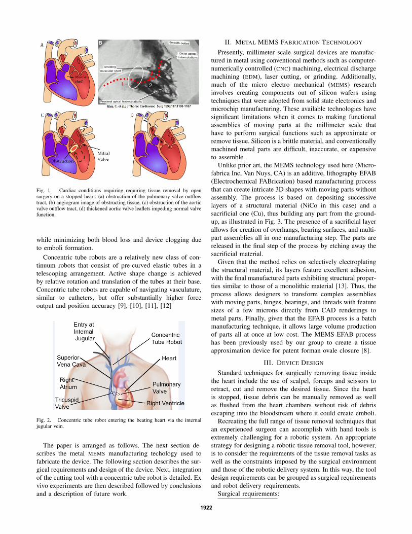
Fig. 1. Cardiac conditions requiring requiring tissue removal by opensurgery on a stopped heart: (a) obstruction of the pulmonary valve outflowtract, (b) angiogram image of obstructing tissue, (c) obstruction of the aorticvalve outflow tract, (d) thickened aortic valve leaflets impeding normal valvefunction.
while minimizing both blood loss and device clogging dueto emboli formation.
Concentric tube robots are a relatively new class of con-tinuum robots that consist of pre-curved elastic tubes in atelescoping arrangement. Active shape change is achievedby relative rotation and translation of the tubes at their base.Concentric tube robots are capable of navigating vasculature,similar to catheters, but offer substantially higher forceoutput and position accuracy [9], [10], [11], [12]
Fig. 2. Concentric tube robot entering the beating heart via the internaljugular vein.
The paper is arranged as follows. The next section de-scribes the metal MEMS manufacturing techology used tofabricate the device. The following section describes the sur-gical requirements and design of the device. Next, integrationof the cutting tool with a concentric tube robot is detailed. Exvivo experiments are then described followed by conclusionsand a description of future work.
II. METAL MEMS FABRICATION TECHNOLOGY
Presently, millimeter scale surgical devices are manufac-tured in metal using conventional methods such as computer-numerically controlled (CNC) machining, electrical dischargemachining (EDM), laser cutting, or grinding. Additionally,much of the micro electro mechanical (MEMS) researchinvolves creating components out of silicon wafers usingtechniques that were adopted from solid state electronics andmicrochip manufacturing. These available technologies havesignificant limitations when it comes to making functionalassemblies of moving parts at the millimeter scale thathave to perform surgical functions such as approximate orremove tissue. Silicon is a brittle material, and conventionallymachined metal parts are difficult, inaccurate, or expensiveto assemble.
Unlike prior art, the MEMS technology used here (Micro-fabrica Inc, Van Nuys, CA) is an additive, lithography EFAB(Electrochemical FABrication) based manufacturing processthat can create intricate 3D shapes with moving parts withoutassembly. The process is based on depositing successivelayers of a structural material (NiCo in this case) and asacrificial one (Cu), thus building any part from the ground-up, as illustrated in Fig. 3. The presence of a sacrificial layerallows for creation of overhangs, bearing surfaces, and multi-part assemblies all in one manufacturing step. The parts arereleased in the final step of the process by etching away thesacrificial material.
Given that the method relies on selectively electroplatingthe structural material, its layers feature excellent adhesion,with the final manufactured parts exhibiting structural proper-ties similar to those of a monolithic material [13]. Thus, theprocess allows designers to transform complex assemblieswith moving parts, hinges, bearings, and threads with featuresizes of a few microns directly from CAD renderings tometal parts. Finally, given that the EFAB process is a batchmanufacturing technique, it allows large volume productionof parts all at once at low cost. The MEMS EFAB processhas been previously used by our group to create a tissueapproximation device for patent forman ovale closure [8].
III. DEVICE DESIGN
Standard techniques for surgically removing tissue insidethe heart include the use of scalpel, forceps and scissors toretract, cut and remove the desired tissue. Since the heartis stopped, tissue debris can be manually removed as wellas flushed from the heart chambers without risk of debrisescaping into the bloodstream where it could create emboli.
Recreating the full range of tissue removal techniques thatan experienced surgeon can accomplish with hand tools isextremely challenging for a robotic system. An appropriatestrategy for designing a robotic tissue removal tool, however,is to consider the requirements of the tissue removal tasks aswell as the constraints imposed by the surgical environmentand those of the robotic delivery system. In this way, the tooldesign requirements can be grouped as surgical requirementsand robot delivery requirements.
Surgical requirements:
1922

Fig. 3. Metal MEMS fabrication process - revolute joint example. Theformation of each layer involves three steps: (a) pattern deposition ofa structural metal, (b) blanket deposition of sacrificial metal, and (c)planarization. After all layers are formed, the sacrificial metal is removed,leaving behind the assembled 3D device.
1) Tissue to be removed may consist of only thin surfacelayers or may form thick muscular layers.
2) Tool must effectively cut (without excessive tearing)endocardial tissue layer which is extremely strong andelastic.
3) Tissue debris cannot escape into the blood stream ifit is large enough to create emboli (diameter > 50microns).
4) Blood loss arising from aspiration should be limited.Robotic delivery requirements:1) Tool / robot diameter is limited to 3 mm to enable per-
cutaneous delivery through the vasculature in childrenand adults (8 mm diameter catheters have been usedfor adult aortic valve replacement).
2) Cutting tool power must be delivered through the robotas its curvature and length varies.
3) Morselized tissue must also be evacuated through thelumen of the robot without becoming jammed in eithertool or lumen.
Together these requirements can be combined to producea set of tool design requirements as described below.
Functional design requirements:1) Tool must be capable of cutting tissue at its tip in order
to enable removal of thick muscular layers.2) To provide precise control for the removal of surface
layers, tool should have a cutting guard that preventsundesired deep cutting as a result of cardiac cyclemotion.
3) The tool design should be scalable in diameter inorder to provide the means to trade off tissue removalprecision with removal rate.
4) To ensure entrainment and transport of tissue debriswhile minimizing blood loss, tool should provide in-tegrated irrigation as well as aspiration.
No existing medical devices meet these functional re-quirements. While there are biopsy catheters, they are onlycapable of taking small bites of tissue and so cannot beused effectively for either the removal of surface layers or
the removal of bulk tissue. Existing powered instrumentsfor the mechanical removal of tissue are typically too largeand are designed as a pair of concentric closed rotatingtubes with a cutting window on the side. Tissue removaldepends on the herniation of tissue into the window - adesign which has limited effectiveness at small diametersand for smooth tissue surfaces. Furthermore, since the cuttingwindow is located on the side of the tip of the tool, they areincapable of performing plunge cuts or sculpting the tissueto create a desired surface profile. Thus, a completely newtissue removal technology is needed to meet the functionalrequirements.
A. Design Features
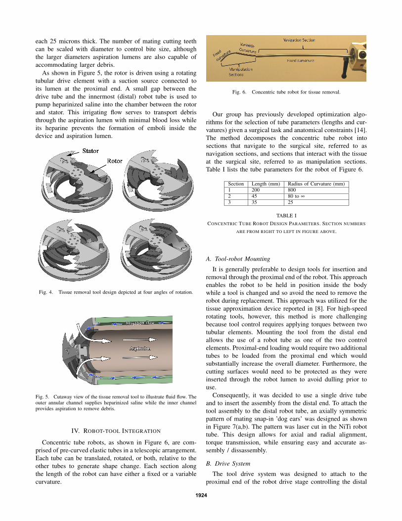
Unlike the machining of stiff materials such as bone andmetal, a cutting device for soft tissue cannot rely on thereaction force of the tissue to generate sufficient force forcutting. Furthermore, capture of debris necessitates a cuttingaction in which the tissue “chips” that are generated areentrained in a flow leading into the cutter head and not thebloodstream. These requirements suggest a stator / rotor toolgeometry for producing a scissoring action on the tissue.
We have produced many different cutting tools of thistype, one of which is depicted in Figure 4. The light graycomponent acts as the stator and is fixed to the distal tube ofthe robot. It includes two large cutting windows 180 degreesapart. The rotor, shown in dark gray, rotates relative to thestator and possesses two sets of five sharp cutting teeth thatgrab any tissue projecting into the cutting windows of thestator.
The sharp leading edges of the stator and the rotor enablethe device to grab and slice the tough endocardial tissuelayer. The multiple sets of interlocking teeth in each windowensure that the entrained tissue is cut into smaller pieces.Ideally, morsel size should be about 1/10th the diameter ofaspiration lumen to aid transport and minimize the potentialof clogging. The number of teeth are selected to balancethis desired bite size with mechanical strength of the cuttingcomponents.
Even though the tool will not be operating while it isbeing navigated over the surface of the beating heart to thesurgical site, it is important to provide the means for avoidingaccidental tissue damage that could occur if the sharp edgesof the tool dig into the tissue. To prevent this, the outerportions of the stator that are not cutting windows functionas cutting guard surfaces. When the tool is drawn acrosstissue such that the stator guards are in contact, the tissueis protected from these sharp edges - even when the tool isoperating. To perform cutting, the tool must be turned onand moved so as to direct tissue into the cutting windows.
Since the MEMS fabrication process used to create thesetools builds the devices from thin planar layers, device costand complexity is closely tied to the number of layers. Anadvantage of the rotor-stator design is that its diameter canbe easily scaled, e.g., from 1-5 mm, using approximatelythe same number of layers. The depicted version has adiameter of 1.8 mm and was fabricated from 36 layers,
1923
each 25 microns thick. The number of mating cutting teethcan be scaled with diameter to control bite size, althoughthe larger diameters aspiration lumens are also capable ofaccommodating larger debris.
As shown in Figure 5, the rotor is driven using a rotatingtubular drive element with a suction source connected toits lumen at the proximal end. A small gap between thedrive tube and the innermost (distal) robot tube is used topump heparinized saline into the chamber between the rotorand stator. This irrigating flow serves to transport debristhrough the aspiration lumen with minimal blood loss whileits heparine prevents the formation of emboli inside thedevice and aspiration lumen.
Fig. 4. Tissue removal tool design depicted at four angles of rotation.
Fig. 5. Cutaway view of the tissue removal tool to illustrate fluid flow. Theouter annular channel supplies heparinized saline while the inner channelprovides aspiration to remove debris.
IV. ROBOT-TOOL INTEGRATION
Concentric tube robots, as shown in Figure 6, are com-prised of pre-curved elastic tubes in a telescopic arrangement.Each tube can be translated, rotated, or both, relative to theother tubes to generate shape change. Each section alongthe length of the robot can have either a fixed or a variablecurvature.
Fig. 6. Concentric tube robot for tissue removal.
Our group has previously developed optimization algo-rithms for the selection of tube parameters (lengths and cur-vatures) given a surgical task and anatomical constraints [14].The method decomposes the concentric tube robot intosections that navigate to the surgical site, referred to asnavigation sections, and sections that interact with the tissueat the surgical site, referred to as manipulation sections.Table I lists the tube parameters for the robot of Figure 6.
Section Length (mm) Radius of Curvature (mm)1 200 8002 45 80 to ∞
3 35 25
TABLE ICONCENTRIC TUBE ROBOT DESIGN PARAMETERS. SECTION NUMBERS
ARE FROM RIGHT TO LEFT IN FIGURE ABOVE.
A. Tool-robot Mounting
It is generally preferable to design tools for insertion andremoval through the proximal end of the robot. This approachenables the robot to be held in position inside the bodywhile a tool is changed and so avoid the need to remove therobot during replacement. This approach was utilized for thetissue approximation device reported in [8]. For high-speedrotating tools, however, this method is more challengingbecause tool control requires applying torques between twotubular elements. Mounting the tool from the distal endallows the use of a robot tube as one of the two controlelements. Proximal-end loading would require two additionaltubes to be loaded from the proximal end which wouldsubstantially increase the overall diameter. Furthermore, thecutting surfaces would need to be protected as they wereinserted through the robot lumen to avoid dulling prior touse.
Consequently, it was decided to use a single drive tubeand to insert the assembly from the distal end. To attach thetool assembly to the distal robot tube, an axially symmetricpattern of mating snap-in ’dog ears’ was designed as shownin Figure 7(a,b). The pattern was laser cut in the NiTi robottube. This design allows for axial and radial alignment,torque transmission, while ensuring easy and accurate as-sembly / dissassembly.
B. Drive System
The tool drive system was designed to attach to theproximal end of the robot drive stage controlling the distal
1924
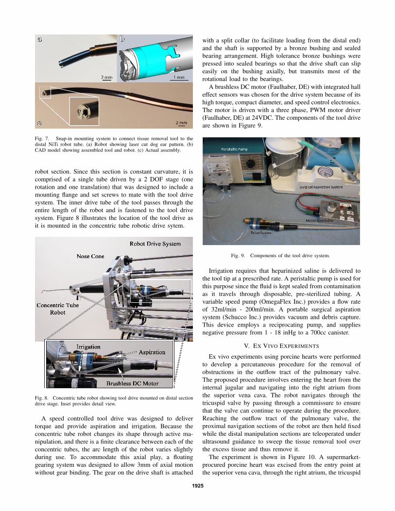
Fig. 7. Snap-in mounting system to connect tissue removal tool to thedistal NiTi robot tube. (a) Robot showing laser cut dog ear pattern. (b)CAD model showing assembled tool and robot. (c) Actual assembly.
robot section. Since this section is constant curvature, it iscomprised of a single tube driven by a 2 DOF stage (onerotation and one translation) that was designed to include amounting flange and set screws to mate with the tool drivesystem. The inner drive tube of the tool passes through theentire length of the robot and is fastened to the tool drivesystem. Figure 8 illustrates the location of the tool drive asit is mounted in the concentric tube robotic drive sytem.
Fig. 8. Concentric tube robot showing tool drive mounted on distal sectiondrive stage. Inset provides detail view.
A speed controlled tool drive was designed to delivertorque and provide aspiration and irrigation. Because theconcentric tube robot changes its shape through active ma-nipulation, and there is a finite clearance between each of theconcentric tubes, the arc length of the robot varies slightlyduring use. To accommodate this axial play, a floatinggearing system was designed to allow 3mm of axial motionwithout gear binding. The gear on the drive shaft is attached
with a split collar (to facilitate loading from the distal end)and the shaft is supported by a bronze bushing and sealedbearing arrangement. High tolerance bronze bushings werepressed into sealed bearings so that the drive shaft can slipeasily on the bushing axially, but transmits most of therotational load to the bearings.
A brushless DC motor (Faulhaber, DE) with integrated halleffect sensors was chosen for the drive system because of itshigh torque, compact diameter, and speed control electronics.The motor is driven with a three phase, PWM motor driver(Faulhaber, DE) at 24VDC. The components of the tool driveare shown in Figure 9.
Fig. 9. Components of the tool drive system.
Irrigation requires that heparinized saline is delivered tothe tool tip at a prescribed rate. A peristaltic pump is used forthis purpose since the fluid is kept sealed from contaminationas it travels through disposable, pre-sterilized tubing. Avariable speed pump (OmegaFlex Inc.) provides a flow rateof 32ml/min - 200ml/min. A portable surgical aspirationsystem (Schucco Inc.) provides vacuum and debris capture.This device employs a reciprocating pump, and suppliesnegative pressure from 1 - 18 inHg to a 700cc canister.
V. EX VIVO EXPERIMENTS
Ex vivo experiments using porcine hearts were performedto develop a percutaneous procedure for the removal ofobstructions in the outflow tract of the pulmonary valve.The proposed procedure involves entering the heart from theinternal jugular and navigating into the right atrium fromthe superior vena cava. The robot navigates through thetricuspid valve by passing through a commissure to ensurethat the valve can continue to operate during the procedure.Reaching the outflow tract of the pulmonary valve, theproximal navigation sections of the robot are then held fixedwhile the distal manipulation sections are teleoperated underultrasound guidance to sweep the tissue removal tool overthe excess tissue and thus remove it.
The experiment is shown in Figure 10. A supermarket-procured porcine heart was excised from the entry point atthe superior vena cava, through the right atrium, the tricuspid
1925

valve, and into the right ventricle to enable visualization ofthe robot and the progression of cutting. The heart was thenimmobilized by suturing it to an aluminum fixture. Finally,the heart and fixture were placed in an anatomically correctlocation with respect to the robot for entry at the jugular.
Fig. 10. Ex vivo experimental set up.
A. Selection of Cutting Parameters
Experimentally optimized values of rotation rate, irrigationflow, and aspiration pressure were obtained through testingdifferent types of cardiac tissue prior to the ex vivo surgicalexperiments. Variation of the rotation rate has a considerableeffect on the cutting behavior. High rotation speeds are veryeffective at removing a thin layer of endocardium, as shownin the upper portion of Figure 11. Slower speeds yield betterresults for removal of bulk material. For both settings, theaspiration and irrigation parameters were set to 15 inHgvacuum and 100 ml/min flow, respectively. At these settings,there is an accumulation of fluid on the cutting surface, butno visually observable tissue debris.
B. Cutting Results
Figure 11 shows results from the cutting experiments ontwo types of tissue. Near the top, removal of the endocardialsurface layer was performed with a gentle sweeping motionalong the surface, with the tool positioned at an angle of45 degrees from normal Note that the underlying musculartissue is exposed, and that the shiny, smooth endocardium hasbeen removed in a roughly rectangular pattern. Lower downin the figure, a cavity was milled into the tissue by pressingthe tool into the tissue with a normal approach and sweepingit in a small circular pattern to expose the surrounding tissueto the cutting windows of the tool.
While little cutting debris was visible on the tissue surface,a downstream embolization filter will be deployed in themain pulmonary artery in future in vivo experiments tocollect any particulate emboli that may be dislodged by theprocess of tissue removal.
VI. CONCLUSIONS AND FUTURE WORK
Successful application of robotics in surgery necessitatesthe creation of new approaches, techniques and tools. Thispaper provides such an approach to a previously unaddressedclinical need - removing tissue inside a beating heart. Wehave proposed and fabricated a solution that incorporatestwo promising novel technologies: metal MEMS tools andconcentric tube robots. This robotic system provides a steer-able yet stiff platform for controlling tool-tissue contact so
Fig. 11. Ex vivo robotic tissue removal near the outflow tract of thepulmonary valve. Illustrated cutting tasks include removal of endocardialsurface layer and also bulk removal of myocardium.
as to enable precise tissue removal while also satisfying thestringent constraints of operating inside the beating heart.Toward our goal of in vivo testing, systematic studies areplanned to evaluate tool tip stability and cutting accuracyon moving tissue and to further characterize the relationshipbetween tool speed, feed rate, irrigation and aspiration aswell as their effect on cutting performance.
REFERENCES
[1] M. Ikeuchi and K. Ikuta, “Development of pressure-driven microactive catheter using membrane micro emboss following excimerlaser ablation (MeME-X) process,” in IEEE Int. Conf. Robotics andAutomation, 2009, pp. 4358–4361.
[2] S. Kesner and R. D. Howe, “Design and control of motion compensa-tion cardiac catheters,” in IEEE Int. Conf. Robotics and Automation,2010, pp. 1059 – 1065.
[3] D. Camarillo, C. Milne, C. Carlson, M. Zinn, and J. Salisbury, “Me-chanics modeling of tendon-driven continuum manipulators,” IEEETrans. Robot, vol. 24, no. 6, pp. 1262–1273, 2008.
[4] D. Camarillo, C. Carlson, and J. Salisbury, “Configuration trackingfor continuum manipulators with coupled tendon drive.” IEEE Trans.Robot, vol. 25, no. 4, pp. 798–808, 2009.
[5] J. Jayender, R. V. Patel, and S. Nikumb, “Robot-assisted active catheterinsertion: Algorithms and experiments,” Int J Robot Res, vol. 28, no. 9,pp. 1101–1117, 2009.
[6] N. Simaan, K. Xu, A. Kapoor, W. Wei, P. Kazanzides, P. Flint, andR. Taylor, “A system for minimally invasive surgery in the throat andupper airways,” Int J Robot Res, vol. 28, no. 9, pp. 1134–1153, 2009.
[7] A. Madhanir, G. Niemeyer, and J. Salisbury, “The black falcon: Ateleoperated surgical instrument for minimally invasive surgery,” inIEEE/RSJ Int.l Conf. on Intelligent Robots and Systems, 1998, pp.936–944.
[8] E. Butler, C. Folk, A. Cohen, N. Vasilyev, R. Chen, P. del Nido, andP. Dupont, “Metal MEMS Tools for Beating-heart Tissue Approxi-mation,” in IEEE Int. Conf. on Robotics and Automation, 2011, pp.411–416.
[9] P. Dupont, J.Lock, E. Butler, and B. Itkowitz, “Design and controlof concentric tube robots,” IEEE Trans. Robot, vol. 7, pp. 304–306,2010.
[10] M. Mahvash and P. Dupont, “Stiffness control of continuum surgicalmanipulators,” IEEE Trans. Robot, vol. 27, no. 2, pp. 334–345, 2011.
[11] J. Lock, G. Laing, M. Mahvash, and P. Dupont, “Quasistatic modelingof concentric tube robots with external loads,” in IEEE/RSJ Int. Conf.on Intelligent Robots and Systems, 2010, pp. 2325–2332.
[12] D. Rucker, B. Jones, and R. Webster, “A geometrically exact modelfor externally loaded concentric-tube continuum robots,” IEEE Trans.Robot, vol. 26, no. 5, pp. 769–780, 2010.
[13] A. Cohen, G. Zhang, F.-G. Tseng, U. Frodis, F. Mansfeld, and P. Will,“EFAB: rapid, low-cost desktop micromachining of high aspect ratiotrue 3-D MEMS ,” in IEEE Int. Conf. MEMS, 1999.
[14] C. Bedell, J. Lock, A. Gosline, and P. Dupont, “Design optimizationof concentric tube robots based on task and anatomical constraints,”in IEEE Int. Conf. on Robotics and Automation, 2011, pp. 398 – 403.
1926