metalforming sector profile report sic 3444 sheet metal ...infohouse.p2ric.org/ref/01/00892.pdf ·...
TRANSCRIPT

Metalforming Sector Profile Report
SIC 3444 Sheet Metal WorkSIC 3465 Automotive StampingSIC 3466 Crowns and ClosuresSIC 3469 Metal StampingsSIC 3499 Fabricated Metal Products
Prepared by the staff of the Industrial Technology Institute
A deliverable for Task 3.1 of:
An Energy, Environmental,and ManufacturingTechnology Access Strategy for Small-MediumManufacturers: A Technology Reinvestment Project,
and for the
EPA Office of Pollution Prevention and ToxicsDesign for the Environment401 M Street, SWWashington, DC 20460
Industrial Technology Institute2901 Hubbard Road, PO Box 1485Ann Arbor, MI 48106
July 26,1995

Executive Summary
The US Metalforming industry is an important industrial sector contributingsignificantly to the US economy. This report profiles the industry, discussesmetalforming processes, and develops an environmental road-map for pollutionprevention.
US Metalforming Industry Profile
US Metalforming covers a large subset of industrial activities that include sheetmetal forming, automotive stamping, crowns and closures, metal stamping, andmiscellaneous metal fabrications. Each corresponds to a four-digit standardindustrial classification code: SIC 3444 or Sheet Metal Work, SIC 3465 orAutomotive Stampings, SIC Crowns and Closures or SIC 3466, SIC 3469 or MetalStampings, and SIC 3499 or Miscellaneous Fabricated Metal Products.
US Metalforming is prominent in the North-east Atlantic states, Midwestern states,and the Pacific coast states. Most companies are small-to-medium sized. Theindustry consisting of over 16,000 companies employs nearly 560,000 workers andrealizes $120 billion in sales revenues. Metalforming companies use equipmentthat is generally between five to twenty years old. Metalforming processes,suppliers, products, and customers are diverse; most products are component partsor subassemblies for customers who are typically larger companies, in industriessuch as automotive, electronics, appliances, aerospace, computers, etc.
US manufacturers are consolidating their supplier base and requiring suppliers toundergo rigorous quality programs and certification, while dropping long timesuppliers that cannot make the grade. The result has benefited the healthier,usually larger firms and left many smaller firms struggling for new markets. Pricecompetition and product obsolescence have resulted in business losses.
US Metalforming is experiencing changes in manufacturing technologies, processimprovement, product quality, and workforce issues. In addition, US Metalformingis impacted by government regulations. These trends are discussed.
US Metalforming Industry Processes
Metalforming is a broad characterization of a number of metal working processesthat deform metal stock to create useful parts. By this definition, Metalformingincludes forging, cold heading, spinning, roll forming, stamping, and several others.Metalforming is dominated, however, by automotive and metal stamping activity.Because of this dominance of stamping processes, and automotive stamping in
1

particular, this report focuses on automotive stamping. Within stamping, severalsub-processes are described along with material flows and key drivers for qualityand productivity.
A historical evolution of the industry and processes applications is narrated.Metalforming manufacturing processes, chemical and common waste streams, andtechnology changes are covered. Chemicals and waste streams associated withstamping operations are described. Metalforming process equipment and processeshave developed over the years and improved considerably. Technologies consideredbest practice concerning energy and environmental issues are described.
Material flows are described from suppliers to metalformers manufacturing formedproducts using different types of processes to impart varying product attributes.Low-end, standard, and high-end methods are described as alternative scenarios bytype of metalforming process in the context of a typical stamping operation. Costconsiderations, safety, and health issues are addressed. Impact of environmentalconcerns are highlighted.
US Metalforming Industry Regulations
Companies that perform metalforming operations are subject to a number of local,state, and federal regulations intended to control the impact of their manufacturingoperations on the health of their workers and the environment. Much of thisattention stems from the hazardous nature of the drawing compounds and cleaningmaterials used in the metalforming industry. The use of petroleum-basedcompounds to lubricate and cool the workpiece, tooling during processing, and theuse of halogenated and other organic solvents or alkaline cleaners to removedrawing compounds and other surface impurities, places this industry undergovernment regulations.
The most regulated wastes generated by the metalforming industry arehalogenated and non-halogenated cleaning solvents. This is because virginmaterials pose an environmental threat and the spent materials often containadditives and contaminants that are considered even more harmful to theenvironment. All indications are that environmental regulation will only becomemore stringent regarding the use, handling, and disposal of these materials.
USEPA regulations, OSHA, and state agencies have a significant affect on thisindustry. The Clean Air Act, Clean Water Act, hazardous waste regulations, andcommunity right to know guidelines all impact metalformers to varying degrees invarious geographic locations. This report develops a regulatory profile of themetalforming industry and details on practices and procedures industry canunderstand and start to implement to meet or exceed guidelines.
2

Table of Contents
I. METALFORMING INDUSTRY PROFILE
A. Introduction 8
B. Industry Characteristics 91. Introduction and Overview of Industry.. .................................................................................. .92. US Metalforming Industry Volumes ....................................................................................... 10
a) Industry Sales .................................... . ................................................................................. 10b) Industry Employment ......................................................................................................... 11c) Industry Size ........................................................................................................................ 12
3. Industry Distribution............................................................................................................... 13a) Size Distribution of Companies. .......................................................................................... 13b) US Metalforming Geographic Distribution ......................................................................... 15
4. US Metalforming Equipment Statistics .................................................................................. 20a) Metalforming Equipment by Industry Segments .............................................................. .21
5. US Metalforming Production Processes .................................................................................. 23a) Forming Process Classifications.. ....................................................................................... .23b) Massive Forming Processes ................................................................................................. 25c) Press Operations in US Metalforming ................................................................................ 26d) Miscellaneous Processes in US Metalforming .................................................................... 29
6. Process Chemicals and Waste Generation .............................................................................. 30a) Lubricants............................................................................................................................ 30b) Metal Cleaners .................................................................................................................... 31
C. US Metalforming Industry Analysis 321. Value Added and Cost Structures ........................................................................................... 32
a) Value Added in US Metalforming ....................................................................................... 32b) US Metalforming Cost Structure ........................................................................................ 33
2. Captive Shops versus Contract Shops ..................................................................................... 343. US Metalforming Company Ownership .................................................................................. 344. Supplier Industries to US Metalforming................................................................................ .355. US Metalforming Industry Products ....................................................................................... 36
a) Major Products of the Sheet Metal Work Industry ............................................................. 37b) Major Products of the Automotive Stampings Industry ..................................................... 37c) Major Products of the Crowns and Closures Products Industry......................................... 37d) Major Products of the Metal Stampings Industry ............................................................. .37e) Major Products of the Fabricated Metal Products Industry ............................................... 38
6. US Metalforming Customer Markets ..................................................................................... .39a) Sheet Metal Work Markets ................................................................................................. 39b) Automotive Stampings Markets .......................................................................................... 40c) Crowns and Closures Markets............................................................................................. 41d) Metal Stampings Markets.. ................................................................................................ .42e) Miscellaneous Fabricated Metal Products Markets ............................................................ 43f) Additional Market Considerations*...................................................................................... .44
7. Business Resource Issues ........................................................................................................ 44a) Capital Investment.. ........................................................................................................... .44b) Workforce Skills .................................................................................................................. 46
8. Competitive Issues.. ................................................................................................................. 47a) Competition Among Shops.. ................................................................................................ 47
3

b) Alternative Materials and Processes .................................................................................. .489. Strategic Relationships and Requirements.. .......................................................................... .49
a) Customer Perspectives.. ...................................................................................................... 49b) Business Growth, Positioning, and Strategy ......................................................................c) Sales and Marketing. ...........................................................................................................
“5:
d) Supplier Perspectives .......................................................................................................... 52e) Quality Requirements ......................................................................................................... 54f) Government and Regulations.. ............................................................................................ 55
10. Technology Trends.. ............................................................................................................... 58a) Manufacturing Technology Outlook: .................................................................................. 58b) Advances and Near-Term Changes...................................................................................... 59
D. Data Tables and Reference Resources 611. Geographic Distribution Data ................................................................................................. 612. US Metalforming Machinery In Use Data: ............................................................................ .683. Supplier Linkage Data............................................................................................................. 734. Reference Resources ................................................................................................................ 82
a) Bibliography*..................................... ................................................................................... 82b) Public Record of Financial Data from Firms: ..................................................................... 84c) Databases Searched:. ........................................................................................................... 84d) Data Services Accessed: ...................................................................................................... 84e) Industry Contacts................................................................................................................. 840 Performance Benchmarking Service: ................................................................................. .85g) Market ScoutTM Service:. .................................................................................................... .85
II. METALFORMING SECTOR PROCESS ANALYSIS 87
A. INTRODUCTION 871. Industry Historical Development ............................................................................................ 88
a) Ancient Presses ................................................................................................................... 88b) Screw Presses ...................................................................................................................... 88c) Trip Hammers.. ................................................................................................................... .89d) Simple Drop Hammer.. ........................................................................................................ 90e) Drop Hammer Development.. ............................................................................................. .90f) C-frame Presses.. .................................................................................................................. 90g) Example of Early Pressworking Capability ........................................................................ 91h) Power Press Development 91.......................................... .........................................................i) Power C-frame Presses......................................................................................................... 92j) Hydraulic Presses.. .............................................................................................................. .92k) Dual Moving Bolster Presses1) Hydraulic Presses for Metalworking ................................................................................................................... ......... 94
....................................................................................... 93
B. Overview of Metalforming Processes1. Overview of Metalforming Materials and Delivery ............................................................... .94
a) Flow of Materials ’................................................................................................................. 95b) Hot Rolled Steel Production and Properties ...................................................................... .96c) Pickling Hot Rolled Sheet Coil ........................................................................................... .96d) Lubrication of Hot Rolled Pickled Steel .............................................................................. 97e) Cold Rolling Sheet Coils ..................................................................................................... .99f) Coated Steel Sheet and Coils ............................................................................................... 99g) Zinc Coatings ..................................................................................................................... 100h) Aluminum Coatings .......................................................................................................... 103
4
i) Tin Coatings ....................................................................................................................... 105j) Preprimed Sheet.. ............................................................................................................... 105k) Prepainted Steel.. .............................................................................................................. 1071) Phosphate Coatings.. .......................................................................................................... 108
2. How Stock is Delivered to the Stamping Plant ................................................................... 109a) Reduction of Engineered Scrap Through Good Blanking Practices.. ............................... 110b) Environmental Concerns Attributable to High Percentages of Engineered Scrap.. ........ 110c) Flat Palletized Sheared Blanks ......................................................................................... 110d) Flat Palletized Irregularly-shaped and Developed Blanks.. ............................................. 111
3. Metalforming Lubricants and Selection Criteria.. ................................................................ 112a) Reducing the Number of Lubricants.. ............................................................................... 113b) Guidelines for Choosing Pressworking Lubricants.. ......................................................... 113c) Advantages of Water-based Pressworking Lubricants ..................................................... 116d) Lubrication Application Techniques.. ............................................................................... 119e) Cleaning and Secondary Operation Requirements.. ......................................................... 121f) Metalforming Press Lubricating Oils and Greases ........................................................... 123g) Metalforming Machinery Lubrication Quality Profile.. .................................................... 130
4. Die Materials Treatments, and Coatings.. ............................................................................ 131a) Characteristics of Tool and Die Steels .............................................................................. 132b) Heat-treatment of Die Steels.. ........................................................................................... 134c) Repairing Dies by Welding.. .............................................................................................. 136d) Die Surface Coatings and Treatments.. ............................................................................ 137e) Nonferrous and Nonmetallic Die Materials ...................................................................... 140
5. Metalforming Process Operations ......................................................................................... 145a) Pressworking processes.. ......... . ......................................................................................... 145b) Pressworking Equipment.. ................................................................................................ 147c) Examples of Die and Pressworking Equipment Configurations.. ..................................... 147d) Part Cleaning and Deburring ........................................................................................... 149e) The Effect of Lubricants on the Waste Stream.. ............................................................... 149g) Variables Affecting Productivity and Output.. .................................................................. 150
1. Process Differences.. .............................................................................................................. 1522. Work Practice Differences ..................................................................................................... 1523. The Future of Metal Stamping Technology.. ......................................................................... 153
a) Changing Responsibility of Contract Stampers.. .............................................................. 154b) Developing Teamwork.. ..................................................................................................... 154c) Factors Favoring Metal Stampings over Other Materials.. .............................................. 155d) Production and Economic Factors.. ................................................................................... 156e) Automotive Applications.. .................................................................................................. 156f) Appliance Applications.. ........................ . ............................................................................ 158g) Electrical, Electronic, and Computer Stampings.. ............................................................ 159h) Recyclability ...................................................................................................................... 160
III. REGULATORY ISSUES AND THE METALFORMING INDUSTRY 162
A. Introduction 162
B. Regulatory Profiles 163a) Water Pollution Regulations For Metalformers . . . . . . . . . . . . . . . . . . . . . . . . . . . . . . . . . . . . . . . 163
5

b) Direct Dischargers.................. .......................................................................................... 164c) Indirect Dischargers.. ........................................................................................................ 164d) Storm Water Runoff Control ............................................................................................. 165
C. Hazardous And Regulated Waste Regulations 166a) Identification of Hazardous Waste .................................................................................... 167b) Solid Waste/Hazardous Waste Determinations ................................................................ 168c) Listed Hazardous Waste .................................................................................................... 169d) Characteristics of Hazardous Waste.. ...............................................................................e) Determining A Hazardous Waste Profile ..........................................................................
171
f) Three Classes of Hazardous Waste Generators.. ............................................................... 171
D. Pollution Prevention 173
E. Storage Tanks 174a) Underground Storage Tanks . . . . . . . . . . . . . . . . . . . . . . . . . . . . . . . . . . . . . . . . . . . . . . . . . . . . . . . . . . . . . . . . . . . . . . . . . . . . . . . . . . . . . . . . . . . . . 174b) Above Ground Storage Tanks . . . . . . . . . . . . . . . . . . . . . . . . . . . . . . . . . . . . . . . . . . . . . . . . . . . . . . . . . . . . . . . . . . . . . . . . . . . . . . . . . . . . . . . . . . .174
F. Air Pollution Regulation for Metalformers 176a) Federal Regulatory . . . . . . . . . . . . . . . . . . . . . . . . . . . . . . . . . . . . . . . . .. . . . . . . . . . . . . . . . . . . . . . . . . . . . . . . . . . . . . . . . . . . . . . . . . . . . . . . . . . . . . . . . . . .176b) State Regulatory . . . . . . . . . . . . . . . . . . . . . . . . . . . . . . . . . . . . . . . . . . . . . . . . . . . . . . . . . . . . . . . . . . . . . . . . . . . . . . . . . . 176
G. Super-fund And EPC Right-To-Know Regulations 180a) Reporting Releases . . . . . . . . . . . . . . . . . . . . . . . . . . . . . . . . . . . . . . . . . . . . 181b) Reporting the Use, Storage and Disposal of Hazardous Chemicals . . . . . . . . . . . . . . . . . . . 182
H. Occupational Safety And Health Regulations 184
I. Hazardous Waste Operations And Emergency Response Standard 185a) Control of Hazardous Energy (Lockout/Tagout) . . . . . . . . . . . . . . . . . . . . . . . . . . 186b Confined Spaces . . . . . . . . . . . . . . . . . . . . . . . . . . . . . . . . . . . . 187c) Respiratory-Protection Standard . . . . . . . . . . . . . . . . . . . . . . . . . . . . . . . . . . 188d) Flammable-Storage Requirements . . . . . . . . . . . . . . . . . . . . . . . . ...... 189e) Noise-Exposure Hearing-Conservation Program...................................................................189
J. Department Of Transportation (DOT) Regulations 189
K. Regulatory Forecast 191a) Clean Air Act Amendments Of 1990 ................................................................................. 192b) Clean Water Act ................................................................................................................ 192c) Resource Conservation And Recovery Act......................................................................... 192d) Superfund.. ................................................................................... 193..................................e) Other Environmental Issues ............................................................................................. 193f) OSHA Regulations 194...................................... .......................................................................g) Other Initiatives:. .............................................................................................................. 194h) State Initiatives ................................................................................................................. 195i) Opportunities ..................................................................................................................... 196
6

I. Metalforming Industry Profile
A. Introduction
Objective and ScopeThis report develops a profile of the US metalforming industry.overview of the industry in terms of:
It provides an
l metalforming industry size, industry structure, types of firms, establishmentdemographics, geographic concentration,
l technology base, cost structures, and general operating conditions,supplier linkages, products, markets, and customers,
l process chemicals used in the industry and waste stream characteristics, andl external conditions and trends affecting the industry.
MethodologyA combination of primary and secondary research methods were employed todevelop the metalforming industry profile.
Primary research included interviews with metalformers of all sizes, experts fromtrade groups, independent industry experts, legal consultants, trade press editors,financial representatives, and government and trade representatives. Tradeorganizations consulted include the Association For Manufacturing Technology,Precision Metalforming Association, National Center for Manufacturing Sciences,and the Industrial Technology Institute.
Secondary research involved literature and database searches. A literature reviewof the trade press was conducted. Trade journals searched included: MetalForming, Tooling and Production, American Machinist, Metalworking Engineeringand Marketing, Society of Automotive Engineers Technical Series. In addition,general business periodicals accessed included Nation’s Business, Small BusinessReports, Newsweek, Forbes, The Wall Street Journal, and Fortune. Governmentreports and documents accessed include Census of Manufacturers, published by theUS Census Bureau, US Industrial Outlook published by the US Department ofCommerce. Additional literature from the Economic Research Service, USInternational Trade Commission, and the National Science Foundation was alsoreviewed. Annual reports, brochure materials, and 10K reports were scanned.
Information indexes accessed include ASI, SRI, and IIS. Databases searchedinclude ABI/Inform, ProQuest, and general reference indexes, such as Standard andPoors, Moody’s, Dun and Bradstreet, and Ward’s Business Directory. Dun andBradstreet’s Marketplace Business software was accessed. Equipment-use datafrom the American Machinist database, supplier linkages, and customer marketdata were developed through the use of the Market ScoutTM Service at the IndustrialTechnology Institute. The National Institute of Standards and Technology/Michigan Manufacturing Technology Center’s Performance Benchmarking Serviceprovided summary anonymized metalforming industry survey responses onbusiness and operational issues.
8

B. Industry Characteristics
1. Introduction and Overview of Industry
A Brief History of the US Metalforming IndustryAs in the case of the machine tool industry, the metalforming industry in theUnited States was located almost entirely in New England in the 19th Century. Atthe close of the 19th Century its’ center moved southward into the Middle AtlanticStates and Pennsylvania, then into Ohio and into other parts of the Midwest.Development and growth were closely linked with the development and growth ofother industries, such as clocks, small arms and ammunition, textile machinery,ships, railroads, farm machinery, and bicycles. By the turn of the 20th century,several centers had emerged with large numbers of metalformers. These centersincluded Cincinnati, Philadelphia, and Providence, RI. The industry surgedforward in the 1920s with the rapid growth of the automobile industry in Michiganand Illinois. The decline in metalforming in Pennsylvania is linked to the decline ofthe railroad industry’. Today, the leading metalforming states still remain Illinois,Michigan, Ohio, and Connecticut. Automotive products are a significant proportionof formed metal parts. The trade group representing the largest proportion of“contract” metalforming firms is located outside of Cleveland, Ohio: the PrecisionMetalforming Association (PMA).
General Description of the IndustryMetalforming companies are generally grouped into two categories: contractmanufacturers and end product manufacturers. Contract manufacturers are moreclearly recognizable as metalformers. PMA defines a contract metalformer as afirm whose total production contains more than 50% of formed metal partsproduced for final assembly and use in a wide variety of end products. End productmanufacturers, sometimes referred to as “captive manufacturers,” have 50% of theirproduction in formed metal parts but these parts are for their own use. In addition,a large proportion of metalforming equipment is located at firms who are notmetalformers in their primary operations. These firms may have one stampingpress on the plant floor to punch out blanks for an assembled product.
Standard Industrial Classification (SIC) codes that cover metalforming are a subsetof the two-digit SIC: SIC 34. SIC 34 or Fabricated Metal Products is a very broadmajor group covering diverse activities and products. Hence SICs accepted byindustry as representative of metalforming include SIC 3444 or Sheet Metal Work,SIC 3465 or Automotive Stampings, SIC 3466 or Crowns and Closures, SIC 3469 orMetal Stampings, and SIC 3499 or Miscellaneous Fabricated Metal Products.Hence final products using formed parts are also diverse (detailed later).
9

2. US Metalforming Industry Volumes
a) Industry Sales
The US Metalforming industry’s sales volumes are shown in Table 1 below:
Source: 1995 Jan-Mar Marketplace Business Software (Dun and Bradstreet)
US Metalforming, inclusive of sheet metal work, automotive stampings, crowns andclosures, metal stampings, and miscellaneous fabricated metal products, accountsfor $121 billion in sales revenues annually. This roughly equals 2% of the USGross Domestic Product (GDP), estimated at $7 trillion annually. Even though,the majority of the products of these industry segments are components for theautomotive, aerospace, computing, machinery, and other industries, thecontribution of the US metalforming sector is significant; the automotive industry,a major player in the economy, contributes approximately 4% or $265 billionannually to the GDP.
Metal Stampings accounts for nearly 30% of metalforming sales , followed by sheetmetal work at 27%. Automotive stampings account for 21%, followed by misc.fabricated metal products at 15%. Crowns and closures account for only 8% ofmetalforming industry revenues.
Product volumes are likely high in the crowns and closures industry segmentenabling firms in the industry to have higher sales levels (over $200 million)compared to even automotive stampings companies ($38 million). The largenumber of metal stamping companies likely brings down the per firm revenueaverage ($8 million) and this is similar tb the case of fabricated metal productscompanies ($7.7 million). Sheet metal work companies average $5 million annuallyin sales; with a large component of total sales revenues, it is likely there are aneven larger number of smaller companies. This interpretation of sales volume datawith reference to firm sizes is examined in a later section.
10

b) Industry Employment
Total employment in US metalforming by industry segment is:
Table 2: Employment EMPLOYMENT BY SICs:
Average Emps.
SIC Industry Segment Total Emps. % of Total per Company
3444 Sheet Metal Work 161,045 29% 23
3465 Automotive Stampings 124,488 22% 150
3466 Crowns and Closures 9,232 2% 128
3469 Metal Stampings 190,596 34% 38
3499 Misc. Fabricated Metal 73,425 13% 29. . . ._. . ._ . . . . . . . . . . . . . . . . . . . . . . . . . . . . . . . . . . . . . . . . . . . . . . . . . . . . . . . . . . . . . . . . . . . . . .. . . . . . . . . . . . . . . . . . . . . . . . . . . . . . . . . . . . . . . . . . . . . . . . . . . . . . . . . . . . . . . . . . . . . . . . . . . . . . . . . . .TOTALS Across Industry 558,786
Source: 1995 Jan-Mar MarketPlace Business Software (Dunn and Bradstreet)
US metalforming across industry segments accounts for 558,786 workers. Theleading employer is the metal stampings segment accounting for 34% of employees,followed by sheet metal work firms accounting for 29% of metalforming employees.Automotive stampings firms account for 22% of metalforming employment, whilemiscellaneous fabricated metal products companies account for 13% ofmetalforming employment. Crowns and closures firms employ only 2% ofmetalforming employees.
On the basis of average employment figures, an average sheet metal work companytypically employs fewer workers relative to miscellaneous fabricated metal productscompanies. Metal stamping companies employ a somewhat larger number. Crownsand closures and automotive stampings companies tend to be the largest employers.Employment averages as portrayed in the table above can only be interpreted as arelative measure;based on the data, a preliminary estimate of industry size can bereached (we will examine industry size issues in a later section as well);automotive stamping and crowns and closures companies are likely fewer thanmetal stampings, miscellaneous fabricated metal products, and sheet metal workcompanies. The next section examines the number of companies across industrysegments of the US Metalforming industry.
11

C) Industry Size
Table 3: Number of CompaniesMETALFORMING INDUSTRY: NUMBER OF COMPANIES
SIC INDUSTRY SEGMENT NUMBER OF COMPANIES % of TOTAL
SIC 3444SIC 3465SIC 3466SIC 3469
SIC 3499TOTAL
Sheet Metal WorkAutomotive StampingsCrowns and ClosuresMetal StampingsMisc. Fabricated Metal
7548 46%889 5%82 1%
5224 32%2536 16%16279
Source: 1995 Jan-Mar Marketplace Business Software (Dunn and Bradstreet)
US Metalforming, inclusive of sheet metal work, automotive stampings, crowns andclosures, metal stampings, and miscellaneous fabricated metal products companies,is comprised of 16,279 companies2. The US Bureau of Census reports this numberas being significantly smaller. However, industry experts and the PrecisionMetalforming Association (PMA) believe that the higher number is more accurate3.
The largest group of companies, at 46% of all metalforming firms, belong to thesheet metal work industry segment, followed by metal stamping companies at 32%of all metalforming firms. Miscellaneous fabricated metal products companiesrepresent only 16% of the industry, followed by automotive stampings companies at5%, and crowns and closures companies at 1% of industry strength.
Our hypothesis in part a) that there are likely a larger number of firms in sheetmetal and metal stampings industry is therefore borne out. In part b) the assertionthat there are likely fewer automotive stampings and crowns and closurescompanies is also verified by the data in table 3 above.
2 MarketPlace Business Software, (January-March 1995), Marketplace Information Corporation,Waltham, MA. All data used by Marketplace Business is from Dun & Bradstreet Corporation.
3 PMA believes census data is inaccurate because firms counted are classified by SIC. Many firmschoose not to be classified as metalformers, but may instead select something that is more marketfocused. An example may be a firm that selects the SIC for “electronic components” if that firmmakes stampings for the electronics industry.
12

3. Industry Distribution
a) Size Distribution of Companies
The following table lists distribution of company sizes across US metalforming:
13
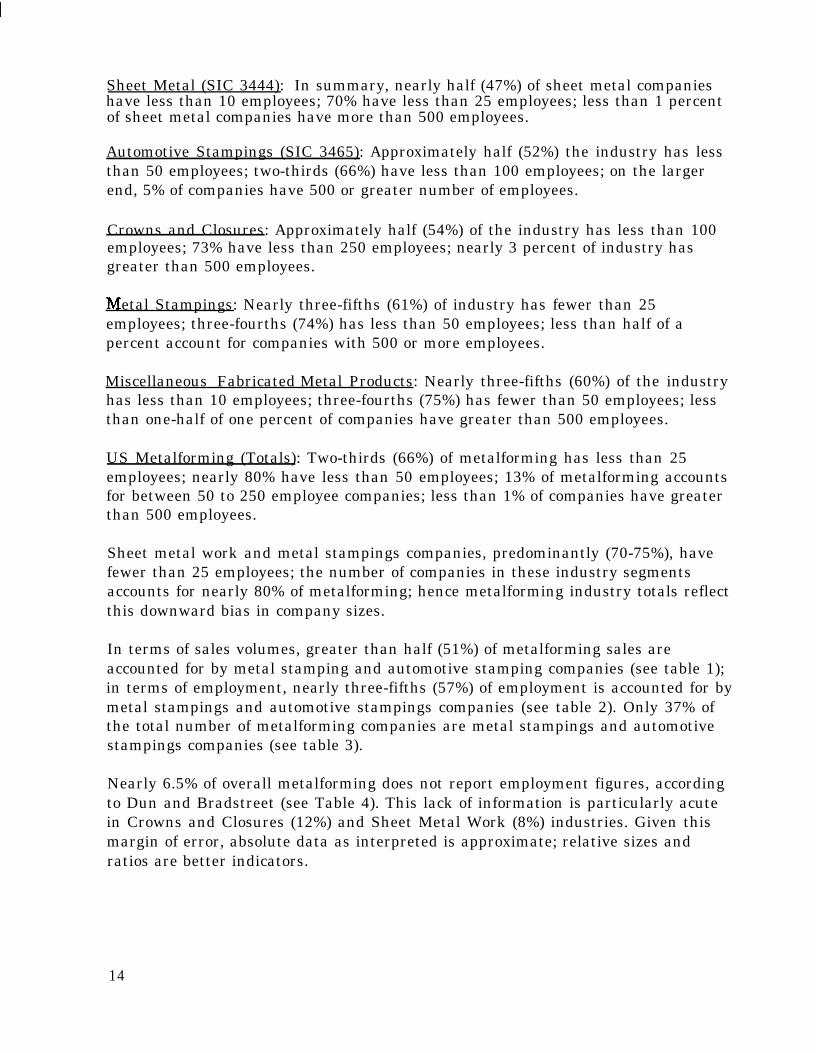
Sheet Metal (SIC 3444): In summary, nearly half (47%) of sheet metal companieshave less than 10 employees; 70% have less than 25 employees; less than 1 percentof sheet metal companies have more than 500 employees.
Automotive Stampings (SIC 3465): Approximately half (52%) the industry has lessthan 50 employees; two-thirds (66%) have less than 100 employees; on the largerend, 5% of companies have 500 or greater number of employees.
Crowns and Closures: Approximately half (54%) of the industry has less than 100employees; 73% have less than 250 employees; nearly 3 percent of industry hasgreater than 500 employees.
etal Stampings: Nearly three-fifths (61%) of industry has fewer than 25employees; three-fourths (74%) has less than 50 employees; less than half of apercent account for companies with 500 or more employees.
Miscellaneous Fabricated Metal Products: Nearly three-fifths (60%) of the industryhas less than 10 employees; three-fourths (75%) has fewer than 50 employees; lessthan one-half of one percent of companies have greater than 500 employees.
US Metalforming (Totals): Two-thirds (66%) of metalforming has less than 25employees; nearly 80% have less than 50 employees; 13% of metalforming accountsfor between 50 to 250 employee companies; less than 1% of companies have greaterthan 500 employees.
Sheet metal work and metal stampings companies, predominantly (70-75%), havefewer than 25 employees; the number of companies in these industry segmentsaccounts for nearly 80% of metalforming; hence metalforming industry totals reflectthis downward bias in company sizes.
In terms of sales volumes, greater than half (51%) of metalforming sales areaccounted for by metal stamping and automotive stamping companies (see table 1);in terms of employment, nearly three-fifths (57%) of employment is accounted for bymetal stampings and automotive stampings companies (see table 2). Only 37% ofthe total number of metalforming companies are metal stampings and automotivestampings companies (see table 3).
Nearly 6.5% of overall metalforming does not report employment figures, accordingto Dun and Bradstreet (see Table 4). This lack of information is particularly acutein Crowns and Closures (12%) and Sheet Metal Work (8%) industries. Given thismargin of error, absolute data as interpreted is approximate; relative sizes andratios are better indicators.
14

b) US Metalforming Geographic Distribution
Figure 1: Distribution of Sheet Metal Work Firms in the US
U.S. SHEET METAL WORK GEOGRAPHIC FIRM CONCENTRATION
NE Atlantic: 1699 Firms
Midwest: 1489 Firms
While California with 1138 companies ranks as the largest single sheet metal work
Massachusetts, Maryland, New Hampshire, Vermont, Maine, Delaware) account forthe largest concentration of firms with 1699 firms; the mid-western region
companies; Pacific coast states (California, Washington, Oregon) rank third with1434 firms (In Figure 1 above). In terms of employment the same pattern is
lowest (also in terms of number of companies). See Table D-l, in Section D, for datadetails.
Table D-l also presents average employment and average sales figures by state.New Mexico has the smallest firms while Missouri has the largest. Sales per firmare lowest in Montana and highest in Rhode Island.

Table D-2 tin section D) presents the geographic distribution of the largestcompanies (defined as having 500 or more employees). Texas ranks first in terms ofboth the number of companies and sales. Ohio has 1 large company with 2500employees. (Missing data on Ohio sales will likely change the ranking on Salesaverage in Table D-2.) The greatest variation can be seen in sales varying between$1.8 billion to $12 million (with the number of companies varying between 4 and 2respectively)
AUTOMOTIVE STAMPINGS
Michigan has just over 50% (446 companies) of all automotive stamping companies(Figure 2 below). The midwestern region has the highest concentration with 616firms; the Pacific coast region has 72 firms; and the North-East Atlantic states have52 firms. Michigan ranks highest in terms of both sales and employment followedby Ohio and Indiana. Ohio has the largest firms while Indiana has the greatest percompany sales. See Table D-3 for data by state.
Figure 2: Distribution of Automotive Stampings Firms in the US
U.S. METALFORMING: AUTOMOTIVE STAMPINGS GEOGRAPHIC FIRMCONCENTRATION

Table.D-4, in Section D, illustrates that Michigan and Ohio account for over 60% ofthe largest firms as well as total employment. In terms of sales, New Jersey leadsin total sales; New York appears to have the largest employers while California hasthe highest per firm sales.
CROWNS AND CLOSURES
Figure 3, below, illustrates that the North-East Atlantic states (Pennsylvania, NewYork, Connecticut, New Jersey, Maryland, Vermont, Massachusetts) account for thelargest number of crowns and closures establishments for a total of 37 firms. Themidwestern region has only 23 firms (Michigan, Illinois, Indiana, Ohio, andWisconsin). Pennsylvania has the largest number of firms (21) in this industry (SeeTable D-3). California in the Pacific coast region has 7 firms and ranks third afterthe midwest in terms of geographic concentration.
Figure 3: Distribution of Crowns and Closures Firms in the USU.S. METALFORMING: CROWNS AND CLOSURES GEOGRAPHIC FIRM
CONCENTRATION
Pennsylvania and Illinois rank highest in terms of number of Crowns and Closurescompanies, employment, and sales (See Table D-5 in Section D). Average
17

employment is highest in Illinois as well as per-firm sales followed by firms inPennsylvania.
Table D-6, in Section D, shows Illinois as the lone state with firms greater than 500employees.
METAL STAMPINGS
The Midwestern region accounts for 1753 firms and ranks as the region with thehighest concentration of metal stamping firms (Figure 4 below). The North-EastAtlantic states follow with 1385 firms; Pacific coast states rank third overall intotal number of stamping companies.
Figure 4: Distribution of Metal Stampings Firms in the US
U.S. METALFORMING: METAL STAMPINGS GEOGRAPHIC FIRM CONCENTRATION I
While California with 632 companies ranks as the largest state with metalstamping companies, the midwestern region states follow closely in number (seeTable D-7). Ohio and Illinois firms provide the greatest employment as well astotal sales among all the 49 states where metal stampers are found. Delaware has
18

the highest per-firm sales average; Wyoming appears to have the largest per-firmnumber of employees followed by Tennessee. See Table D-7 for details.
The largest number of metal stampers are located in Wisconsin followed by NewYork (Table D-8 in Section D). These two states also lead amongst the larger metalstampers in terms of sales and employment. Minnesota apparently has the largestmetal stampers while Ohio’s large metal stampers generate the highest per-firmsales revenue.
MISCELLANEOUS FABRICATED METAL PRODUCTS
Figure 5, below, illustrates the fact that the North-East Atlantic states lead as ageographic region of concentration with 619 firms followed by the Midwest with 478firms. Third-ranked is the Pacific coast region with 426 companies.
Figure 5: Distribution of Fabricated Metal Products Firms in the US
U.S. METALFORMING: MISC. FABRICATED METAL PRODUCTS GEOGRAPHIC FIRMCONCENTRATION
Table D-9, in Section D, details state-by-state firm data. California with 351 firmshas the largest number of miscellaneous fabricated metal products companies.
NE Atlantic: 619 Firms
Midwest: 478 Firms Pacific: 426 Firms
19

However, Illinois companies provide the greatest employment and post highest totalsales. The largest per-firm employment is found in Delaware; highest per-firmsales occur in New Hampshire. The largest companies are found in Pennsylvania,New York, and Illinois, with highest total employment. New Jersey leads in totalsales. (Table D-10, Section D).
4. US Metalforming Equipment Statistics
According to American Machinist, newer machinery is gradually being adopted inUS manufacturing with a definite albeit slow transition towards new machines insmaller firms. This observation appears consistent with the intuitive perceptionthat larger plants tend to be older ones in any industry (because of time dynamicsof capital investments, industry shake-outs and firm stability, etc. ); therefore largerplants are usually expected to have older machinery.
Table 5, below, shows the types of machinery and total units in use in USmetalforming, as well as age of machinery on the shopfloor. We will examine typesof machines by industry segment as well later.
Numerical Control (NC) equipment, in general, tends to be younger. The youngestmachines (less than 5 years old) are NC punching and shearing; NC bending andforming; and other NC metalforming machines. Pneumatic presses, sheet and plateprocessing systems, and die-casting machines are typically less than ten years old.
20

The oldest equipment, generally over 20 years old, are mechanical presses, forgingmachines, and thread-rolling machines. All other machinery is typically between10 to 20 years of age.
It is worth noting that of all metalforming machinery, 33% are mechanical presses,followed by non-NC bending and forming machines at 17.9% and non-NC punchingand shearing machines at 16.7% of total metalforming machinery. Only 4% of allmetalforming machinery incorporates computer numerical control.
We now examine the age distribution of machinery by plant size in Table 6, below:
Note that machinery less than 5 years old is evenly distributed across all sizes ofmetalforming plants. The smallest companies with 1-19 employees have the largestpercentage. Newer machines in smaller companies become even more prominentfor machinery aged less than 10 years old. Twenty years or more aged machinery ispredominantly found in large plants.
a) Metalforming Equipment by Industry Segments
This section summarizes data that is detailed in Section D, Tables D- 11 through D-15. Most reported machinery is mentioned in the section below; other machinery,not mentioned here, can be found in the additional data tables in Section D.
(1) SHEETMETAL WORK
Most Sheet Metal Work companies own non-NC drilling machines, cutoff andsawing machines, punching machines, plate and sheet shears, non-NC bending andforming machines, and welding equipment. The largest percentage of machineryamong all machines on a typical shop-floor includes drilling machines, cutoff andsawing machines, plate and sheet shears, non-NC bending and forming machines,and mechanical presses. Welding equipment exceeds all other machines in sheetmetal companies. See Table D-11, in Section D, for details.
21

(2) Automotive Stampings
Most Automotive Stampings companies own non-NC turning machines, non-NCdrilling machines, non-NC milling machines, non-NC grinding machines, cutoff andsawing machines, mechanical presses, non-NC bending and forming machines,welding equipment, inspection and measuring machines, and computerworkstations. The largest percentage of machines among all machines on a typicalautomotive stamping shop-floor includes open back and gap and single point,mechanical presses, welding equipment, cutoff and sawing machines, and non-NCdrilling machines. See Table D-12, in Section D, for more details.
(3) CROWNS AND CLOSURES
Most Crowns and Closures companies own non-NC turning machines, non-NCdrilling machines, non-NC milling machines, non-NC grinding machines, cutoff andsawing machines, mechanical presses, welding equipment, optical comparators, andbaking and drying ovens. The largest percentage of machines among all machineson a typical crowns and closures shop-floor includes open back and gap, up to 50tons mechanical presses, thread rolling machines, non-NC turning machines,baking and drying ovens, and welding. See Table D-13, in Section D, for moredetail.
(4) M E T A L S T A M P I N G S
Most Metal Stampings companies own non-NC turning machines, non-NC drillingmachines, non-NC milling machines, non-NC grinding machines, cutoff and sawingmachines, mechanical presses, welding equipment, and optical comparators. Thelargest percentage of machines among all machines on a typical metal stampingsshop-floor includes open back and gap and other mechanical presses, cutoff andsawing machines, and non-NC grinding, milling, drilling, and turning machines.See Table D-14, in Section D, for more details.
(5) MISC. FABRICATED METAL PRODUCTS
Most fabricated metal products companies own non-NC turning, milling, drillingand grinding machines, cutoff and sawing machines, punching machines,mechanical presses, and welding equipment. The largest percentage of machinesamong all machines on a typical fabricated metal products firm’s shop-floorincludes welding equipment, cutoff and sawing machines, and non-NC drilling andturning machines. See Table D-15, in Section D, for more machinery details.
22

5. US Metalforming Production Processes
This section presents a summary description of forming process classificationmethods, brief descriptions of typically massive forming processes and sheetmetalforming processes, press operations in the metalworking industry, and briefdescriptions of miscellaneous processes in metalforming companies.
a) Forming Process Classifications
Forming processes4 can be classified according to various parameters involved inthe forming process namely, temperature, stress state, and flow pattern. The tablebelow illustrates the combination of these parameters which define various formingprocesses:
Table 7: Forming Processes: A ClassificationForming Process Temperature Stress State Flow PatternDeep Drawing Hot Indirect Compression DynamicExtrusion Hot or Cold Direct Compression Quasi-static/DynamicForging Hot or Cold Direct Compression DynamicRolling Hot or Cold Direct Compression Quasi-staticStretch Forming Cold Biaxial Tension DynamicWire Drawing Cold Indirect Compression Quasi-static
Brief descriptions of each forming process follow below. Detailed descriptions canbe found in the ‘Metalforming Process Report,’ section (Part II of this MetalformingSector Report).
(1) DEEP DRAWING
A plastic forming process in which a flat sheet of material is formedinto a recessed three-dimensional part with a depth several times thethickness. As a punch descends into the die, the material is shapedinto a three-dimensional configuration.
(2) EXTRUSION
The workpiece is compressively forced to flow through a shaped die toform a product with a reduced cross-section. Most commonly, materialis placed inside a confining chamber and a ram moves through itforcing the material through the die.
4 Material in this section has been adapted from ‘Forming Processes,’ Ronald A. Kohser and ChesterJ. Van Tyne, Chapter 4.3, (1987), John A. White, Editor, Production Handbook, John Wiley andSons, New York.
23

(3) FORGING
The workpiece may be drawn out, increasing length and decreasingcross-section; upset, increasing cross-section and decreasing length; orsqueezed in closed-impression dies to produce multidirectional flow.
(4) ROLLING
The workpiece is passed between rollers rotating in oppositedirections, the spacing between rollers being less than thickness ofmaterial. Elongation occurs and successive passes determine degree ofdeformation.
(5) STRETCH FORMING
A sheet of metal is gripped by two or more sets of jaws that stretch andwrap material around a formblock. The material assumes the shape ofthe formblock.
(6) WIRE DRAWING
A wire or rod is inserted through a converging die and pulled.Elongation with reduction in cross-section occurs.
(7) COLD WORKING
Cold working is plastic deformation of materials below theirrecrystallization temperatures.
(8) HOT WORKING
Hot Working is plastic deformation of materials above theirrecrystallization temperatures.
(9) WARM WORKING
Deformation at temperatures intermediate to hot or cold working iscalled warm working; ductility may be increased with less tooling wearand less energy use in the process.
24

b) Massive Forming Processes
The following table depicts typical massive forming processes used in parts of themetalforming industry:
ForgingTable 8: Massive Forming ProcessesRolling Extrusion Drawing
Nonlubricated hot DrawingClosed-die forging withflashClosed-die forging withflashCoiningElectra-upsettingForward extrusionforgingBackward extrusionforgingHobbingIsothermal forgingNosingOpen die forgingOrbital forgingP/M forgingRadial forging
Sheet rolling
Shape rolling
Tube rollingRing rollingRotary tube piercing
extrusionLubricated direct hotextrusionHydrostatic extrusion
Drawing with rolls
IroningTube sinking
Gear rolling
Roll forgingCross rollingSurface rollingShear formingTube reducing
Upsetting
In addition, there are also typical sheet metal forming processes; these are outlinedin the table below:
Rubber pad formingMar-form process
Shallow Recessing
Die-quench forming Electromagnetic formingDrop hammer forgingExplosive forming
25

C) Press Operations in US Metalforming
There are several types of press applications: blank, pierce, form, coin, gauge,draw, and deep draw. Types of presses include C-Frame or Gap; mechanical,hydraulic, or pneumatic; blanking, single station, progressive, transfer, and theconventional multiple press line (tandem). A die installed in a press forms thesheet steel into the desired shape, occasionally needing four, five, or six dies to formthe final part.
The following discussion is organized by type of press operation:
(1) MECHANICAL,HYDRAULIC,AND PNEUMATIC PRESSESThese presses function alone or are arranged front to back by function with theslow, double action presses in the front of the line to perform blanking and thelighter trim or pierce at the end. Presses are described in a variety of ways buttypical descriptions include the tonnage of the press, the length and width of thebed or bolster, the speed of the stroke in “strokes per minute,” and the height of thestroke in inches. Other distinctions include the general shape of the frame, C orGAP, whether it is single or double-action, and whether it is straight-sided ordouble-sided.
Presses arranged sequentially in a line are referred to as Tandem presses. Atypical Tandem press line performs the following functions: Blank, Shape, Trim,Pierce, Flange and/or Trim. Tandem lines, typically, contain six presses; manyfirms have lines with three presses or sometimes may have as many as seven. Rawmaterial is fed in from a coil or from blanks. Larger part stampings are sometimesautomated in which a robot or a simpler device loads blanks or coiled steel into thefront of each press and removes from the back a formed part. Sometimes, firmshave mismatched lines in which presses are simply lined up regardless of optimumsequential job function in order to consolidate old equipment or space. Presses withdies that perform multiple operations on coil-fed sheet metal are referred to asProgressive-die presses.
Mechanical presses tend to be older, with 80% of equipment on the plant floor beingat least 10 years old. Refer to the discussion on equipment statistics earlier fordetails on equipment populations. Also refer to Section D, tables D-11 to D-15, forSIC 3444,3465,3466,3469, and 3499 data.
New press are added each year to metalworking operations. Data in Table 10 belowprovides US ‘consumption,’ through 1992 (latest available data). US pressconsumption is determined by adding total units of US production of presses toimports and subtracting US exports.
Table 10: US Consumption of Mechanical, Hydraulic and PneumaticPresses
Year 1987 1988 1989 1990 1991 1992Units 3,665 2,913 3,766 4,549 3,162 3,408
Source: AMT Handbook, US Machine Tool Consumption. 1993. Page A-18.
With new presses added to existing presses the estimated mechanical, hydraulic,and pneumatic total press population is between 200,000 and 235,000 presses. This
26

number varies in part due to the variable number of older presses that are in ordrop out of production. The age of presses also indicates the possibility that manyof them may not be fully utilized, and some may be completely unused.
(2) TRANSFER PRESSESThe eyelet press, the precursor of the multistation transfer press, originated as amulti-plunger continuous process machine that specialized in small, metal partssuch as eyelets or ammunition casings. It was commonly found in the shoeindustry. The current equivalent of the eyelet press is a mechanical transfer presswhich is automatic with multiple stations. The work piece is moved from station tostation by a transfer mechanism synchronized with the press action. Although thesize of the mechanical transfer press may determine its particular industrialapplication, all mechanical transfer presses are used for the same general purposeof forming metal parts. Typically the transfer press is cam driven but othermethods are used such as crank and eccentric. The size of transfer presses rangefrom 20 to 3,000 tons. Size is also measured by slide dimensions. A new machinewill cost from $125,000 for the small presses to millions of dollars for the largermachines.
It is estimated by industry experts that there are about 2,000 transfer presses,currently, in use in the US5 6. Transfer presses have a number of differentspecifications, including tonnage capacity, bolster dimensions, and slide length.Although different sizes of transfer presses function in the same manner, the smallpresses (under 150 tons) are a distinct industry and serve very different marketsfrom the firms using the larger tonnage presses (over 150 tons). The age andcondition of the machines is the clearest example of this distinction.
Many small tonnage transfer presses are older machines used for high volumecommodity parts such as ammunition casings, cosmetic tubes, battery cases, andbrass grommets. Presses are run continuously with very few tooling changes.
The inhibitors to using transfer presses are the cost of the machinery and the costof the tooling for the transfer presses. For most firms, switching from tandempresses to transfer presses requires that the tooling of the tandem presses bescrapped.
Large capacity presses are relatively new in the forming industry. Their cost andcomplexity limit them to only the largest markets, such as automotive andappliance industries. They may be imported from Japan, Europe, or produceddomestically and tend to be new machines, usually brought in to replace existingtandem lines7. During the period 1984-1989, the US automakers awarded 40
5 Discussions with Mr. E. Dunbar, General Sales Manager, US Baird Corporation.
6 US Department of Commerce, Survey of Manufacturers, Report MW35W and subsequentconversation with report editor, Mr. Michael Yammer of the Dept. of Commerce, Rockville, MD.
7 “Mechanical Transfer Presses from Japan,” (February 1990), Report no, 2257US, InternationalTrade Commission {USITC],. pages Al5 and A32.
27

contacts for 113 large transfer presses valued at $690 million. These presses hadan average price of $17.25 million each. The period 1984-1989 saw years of highdemand from the automotive industry*. Because of the huge investment requiredfor the large machines, the number of large tonnage presses is estimated to befewer than 250 units in operation, or about 10% of the total number of transferpresses in operation.
Almost all large presses are sold to the automotive industry’: Most transfer pressmanufacturers are interested only in large transfer press orders.l0 In terms ofvalue, about 65% of the total transfer presses sold in the US are imported ll. Of allJapanese transfer presses imported into the US, 99% were used for automotiveparts. The United States International Trade Commission has identified eight USfirms making multi-station transfer presses12. Certain producers manufacture onlythe mechanical press itself, and purchase the entire transfer feed system fromoutside companies that specialize in automation systems.
The advantages of large transfer presses over traditional tandem lines for largepart stampings has been clearly demonstrated and has spurred an acceleratingtrend toward the use of transfer presses13 14.
8 Ibid.
9 “Mechanical Transfer Presses from Japan,” (February 1990), Report no. 2257US, InternationalTrade Commission (USITC],. page 111.
10 American Machinist, (January 1993).
11 USITC Report 2257
12 Ibid
l3 “An Emerging Model for Future Automotive Stamping Plants,” (March 4, 1988), Donald N. Smithand Peter G. Heytler,SAETsechnical Papers Series No. 880211,. Page 6.
14 An excerpt from “Full Automation with .Transfer Presses,” (March 1987), MetalworkingEngineering and Marketing, page 49-50, describes the benefits of transfer presses:
Those companies that do not have a transfer press are now considered as out-of-datemanufacturers. The transfer press has been employed since 1980 with its advantages; highproduction capacity, labor-saving function, and space saving design. Mr. Yamaguchi(managing director of press business department, Komatsu, Ltd.) further said, ‘forproductivity, the stroke of a transfer press has been doubled (20 spm) even for 2,700-3,000ton presses as compared with 8-10 spm in a tandem line). Also the transfer press is socompact that it requires about half the space of a tandem line.‘... Only about five persons,including operators, are required to take care of a line of the transfer presses. Thus morethan half of the personnel can be reduced as compared with conventional tandem lines.
28

Some advantages of using transfer presses are:
Higher production rates (well over 50% higher in some cases)Lower purchase pricesReduced floor spaceLower scrap rates
Even though other factors are also involved in a “World Class Metalforming”operation, especially for the automotive industry, the transfer press has come toplay a major role towards attaining this class of manufacturing because it involvesa significant investment and a high-technology capital commitment which all firmscannot make.
(3) HYBRID SOLUTIONS
Due to the increased demand for transfer presses, prices have risen making themprohibitive to all but the largest and most stable contract metalforming firms.Added features on the presses that make die-change easier have also addedsignificantly to the price.
For this reason, tandem press owners have turned to other automation technologiesto attain production advantages and the business status enjoyed by the transferpress establishments. These technologies include:
High speed press coil feed mechanismsAutomatic die changeRobotics and press loading and unloading mechanismsPress transfer systems that move product automatically from station tostation
d) Miscellaneous Processes in US Metalforming
Miscellaneous processes found in many metalforming operations are listed anddescribed briefly below:
Table 11: Miscellaneous Metalforming ProcessesProcess DescriptionAssembly Staking, brazing, riveting, and stacking are examplesBoring Internal diameters are generated in true relation to the centerline of the
spindle by means of single-point cutting tools, and is most commonly usedfor enlarging or finishing holes or other circular contours.
Countersinking Using a drill press, e.g., circumference of a hole is tapered to receive afastener, for receiving a center, or for deburring.
Deburring Removing sharp edges by e.g., tumbling, vibrofinishing, sanding, andbuffing.
Design Changes in tool configurations to preserve tool life, work-piece finish,dimensional accuracy, or productivity.
Drilling
29

Process DescriptionDuplicating
ElectricalDischargeMachiningFinishingGear Cutting
GrindingHoning
LappingMillingPlastic MoldingTapping
Turning
Welding
Generating external surfaces by action of a cutting tool on a rotatingworkpiece.Regularly spot and arc welding, using steel, stainless steel, and aluminum.
Adapting to internal and external contours using tracer and numericalcontrol lathes.Producing holes, slots or other cavities in electrically conducive material bymeans of the controlled removal of material through melting or vaporizationby high-frequency electrical sparks.Plating, anodizing, painting, conditioning for special coatings.Milling, template machining, format cutting, helixform cutting, cyclexmethod cutting, face-mill cutting, interlocking cutters, two-tool generators,and planing generators are used to cut teeth in spiral and straight gears.Removal of small amounts of metal for high dimensional accuracy.Low-speed surface process for removing stock by shearing action of a honingstone or “stick.”Low-speed, low-pressure abrading process for refinement and high accuracy.Removal of metal by a rotating multiple-tooth cutter.Boring and milling to produce molds for plastics.Preparing the workpiece to accept bolts or screws, by cutting or forminginternal threads.
6. Process Chemicals and Waste Generation
Two forms of fluids are used in metalforming operations. They include lubricantsand metal cleaners. A detailed discussion is presented later in the report.
a) Lubricants
Lubricants are vitally important in metalforming operations. They are used tocontrol friction to reduce force and power requirements and stress in tooling. Theyalso improve product quality. A lubricant’s main function is to minimize surfacecontact between the tooling and the workpiece. ‘They can also provide importantheat dispersion benefits.
Factors that affect the selection of type of lubricant include the operation, tooling,raw materials, application method of thelubricant, subsequent operations, andspecial considerations. The types of oil-based lubricants include mineral oils,mineral fatty oils, mineral fatty chlorinated oil, mineral fatty sulfur oil, mineralfatty chlorinated oil, metallic soaps, and phosphate esters. The water-basedextendible lubricants include mineral soluble oils, fatty soluble oils, fattychlorinated soluble oil, fatty sulfur soluble oil, fatty chlorinated sulfur soluble oil,
30

liquid soap, soap fat paste compound, and synthetics”. Recent trends include usingfilm lubricants and even elimination of lubricants in response to increasingenvironmental concerns and in an effort to reduce cost.
b) Metal Cleaners
Cleaners are used in metalforming to clean residues of the stamping operation aswell as soil and dirt. Cleaning is crucial to prepare the part for ensuing secondaryoperations such as painting. For more than fifty years, manufacturers have cleanedparts by vapor degreasing them with chlorinated solvents. This is being phased outand manufacturers are actively searching for alternatives with reducedenvironmental impact. The main alternative is aqueous cleaning systems”‘. Thisrequires expensive system modifications because of changes in exposure regulationsand because mechanical agitation is required. Factors that affect the selection ofcleaners include the type of dirt to be removed, the surface of the part, the degree ofcleanliness required, safety, water supply, disposal of spent solutions, and themethod of application. Cleaners are usually of two types: solvent cleaners andalkaline cleaners*‘.
Nearly 81% of metalforming companies that use hazardous materials and disposeoff toxic wastes formally track their use and disposal. Nearly 72% of metalformingcompanies have used hazardous materials and disposed off toxic waste in the lasttwo years’“. In addition, 73% of metalforming companies have instituted simplewaste-reduction practices; nearly 55% of companies have re-engineered eitherproducts or manufacturing processes in order to reduce purchase or output ofhazardous or toxic materials’“.
1 6 Tool and Manufacturing Engineers Handbook (1984.), V.2 Forming., Society of ManufacturingEngineers, Dearborn, MI, pages 3.1-3.22.
16 “Metal Cleaning Gets Complicated,” (June 1994.), David T. Curry, Metal Forming, page 36-42.
17 Tool and Manufacturing Engineers Handbook, (1984.), V.2 Forming., Society of ManufacturingEngineers, Dearborn, MI, pages 3.1-3.22
18 Metalforming Sector Performance Benchmarking Report, (1995), Industrial Technology Institute,Ann Arbor, MI.
19 Ibid.
31

C. US Metalforming Industry Analysis
1. Value Added and Cost Structures
a) Value Added in US Metalforming
Many firms in this sector are private or Sub Chapter S corporations. Hence value-added figures are dependent on sales figures and costs of raw materials andservices that are at best approximated from one industry to the next. Table 12below presents estimated value-added figures for each of the industry segments inthe US metalforming industry.
Value-added is highest in `fabricated metal products and lowest in automotivestampings; these figures are only approximations and can vary from one year to thenext. Individual firm data is interesting: the lowest per-firm value added occurs inthe sheet metal work industry segment while the highest per-firm value added is inthe crowns and closures segment. Again this is ‘average’ data and should beinterpreted keeping in mind the approximate nature of the estimates,
32

As shown in the table, approximately 53% of costs are material and service costs inthe US Metalforming industry. These range from 46% in metal stamping firms to57% in automotive stamping companies. Payroll accounts for 29% of USMetalforming costs with 30% in automotive stampings to 26% in sheet metalindustry segments. Margins, as estimated, are approximately 19% in USmetalforming ranging from 13% in automotive stampings to 24% in crowns andclosures and metal stamping companies. Note that these figures are at bestapproximations that have been developed using cost structure informationgenerated by Market ScoutTM based on data from MarketPlace Business and Bureauof Labor Statistics Input-Output Coefficients of the US Economy.
Tables D-16 through D-20 present additional detail on cost components by type ofpurchased input in Section D.
33

2. Captive Shops versus Contract Shops
Of the total number of metalforming companies estimated at 16,279 firms in theUS”“, it is estimated that 30% of the total are end product or captive shops. Thiswould equal 4,884 captive firms. Table 14 shows, further, the breakdown byindustry segment of the metalforming industry.
Approximately, 11,400 firms are contract shops.
3. US Metalforming Company Ownership
Traditionally, metalforming companies have been privately owned. This is stilltrue. Table 15, below, shows that 96% of US metalforming companies are privatelyheld.
While sheet metal companies are predominantly privately owned, with 98% ofprivate firms, crowns and closures firms have more public ownership; 28% of firmsin the crowns and closures industry are publicly owned. Of all automotive
20 MarketPlace Business, (January-March 1995), Dun & Bradstreet
34

stamping companies, 12% are publicly owned. The metal stampings and fabricatedmetal products industries have 96% and 95% of privately owned companies.
4. Supplier Industries to US Metalforming
Supplier industries to the five US metalforming industry segments are describedhere. Note that we only list some of the supplier industries and approximatepurchase dollars. Tables D-16 through D-20 provide a resource for computingpurchases from supplier industries in greater detail.
Sheet Metal Work: The sheet metal work industry’s major supplier industries arelisted below along with the dollar volume of purchases from each supplier industry:
Major Supplier Industry Purchases ($ Millions)Blast furnaces and steel mills $6781.47Aluminum rolling and drawing $2418.02Fabricated structural metal $ 773.64Screw machine products and stampings $ 398.15
Other Sheet Metal Work Companies $ 210.40
Thus the sheet metal work industry segment’s most important suppliers are blastfurnaces and steel mills and aluminum rolling and drawing industries. Also, theindustry buys sheet metal work products valued at $210.4 million. Thus firms selltheir primary product to other firms within the industry.
Automotive Stampings: Supplier industries to the automotive stampings segmentinclude:
Major Supplier IndustryBlast furnaces and steel millsNonelectrical machineryPrimary nonferrous metalsMetal working machineryGeneral industrial machinery
Purchases ($ Millions)$7874.06$2391.14$ 623.34$ 279.26$ 44.88
Other Automotive Stampings Companies $ 107.21
Blast furnaces and steel mills ranks first in terms of dollar transactions, followedby nonelectrical machinery firms, primary nonferrous metals, etc. Automotivestampers buy $107.2 million of stampings from other firms within the industry.
Crowns and Closures: Crowns and closures firms purchase from:
Major Supplier IndustryMetal coating and allied servicesAluminum rolling and drawingBlast furnaces and steel millsPaints and allied productsPlastics and synthetic materials
Purchases ($ Millions)$1596.51$1204.44$ 345.38$ 245.17$ 197.40
Other Crowns and Closures Companies $ 13.62
35

Metal coatings ranks first followed by aluminum rolling and drawing, blastfurnaces and steel mills, etc. Typically, the industry sells primary product to othercrowns and closures firms minimally, only worth $14 million.
Metal Stampings: Metal stampings companies buy materials and products from:
Major Supplier Industry Purchases ($ Millions)Blast furnaces and steel mills $6610.05Aluminum rolling and drawing $1210.04Copper rolling and drawing $ 512.91Plating and polishing $ 281.74
Other Metals Stampings Companies $ 502.07
Blast furnaces and steel mills ranks first followed by aluminum rolling anddrawing, copper rolling and drawing, etc. Intra-industry sales amount to $502million.
Fabricated Metal Products: Supplier industries to miscellaneous fabricated metalproducts firms include:
Major Supplier IndustryBlast furnaces and steel millsAluminum rolling and drawingNonferrous wire drawing and insulatingPrimary aluminum
Purchases ($ Millions)$2795.17$ 540.06$ 245.59$ 215.56
Other Fabricated Metal Products companies $ 798.62
Blast furnaces and steel mills ranks first followed by aluminum rolling anddrawing, nonferrous wire drawing, etc. Intra-industry sales of primary productamounts to nearly $800 million.
Tables D-16 through D-20, in Section D, provide the supplier industry’s ranking interms of percent of output of each industry segment. Therefore, the sales figures inTable 1 when multiplied with the specific supplier industry percentage figure (inTables D-16 to D -20) yields the value of purchase from the supplier industry.These tables can be used to ascertain the value of each supplier industry listed.
These tables also demonstrate the extensive supplier linkage that exists betweenvarious industries and firms in each of the metalforming industry segments.
5. US Metalforming Industry Products
US Metalforming industry products are diverse in their end-product applications.From heavy industrial and durable goods applications such as automotive bodypanels and hub caps, office machine and computer equipment casings andhousings, appliance body casings and panels, to consumer durables such as lawnand garden equipment, forged and formed hardware, residential constructionapplication components, and bicycles and playground equipment, metalformingproducts are found in virtually all types of end-products. Tables 16 to 20 list
36

metalforming products by category of classification, for each of the individualmetalforming industry segments.
a) Major Products of the Sheet Metal Work Industry
Table 16: Sheet Metal Work ProductsMarket Segment Product DescriptorsSheet metal work Cornices, skylights, ceiling domes, copings,
and gravel stopsBins and vatsStove pipes, furnaces, air ductsCulverts, flumes, irrigation pipesMetal roofingRoof drainage equipmentFabricated metal flooringMetal siding
b) Major Products of the Automotive Stampings Industry
Table 17: Automotive Stampings ProductsMarket Segment Product DescriptorsBody Parts, Hubs, and Trim Fenders
TopsHub capsBody panelsTrimMoldingsOther stamped body parts
c) Major Products of the Crowns and Closures Products Industry
Table 18: Crowns and Closures ProductsMarket Segment Product DescriptorsMetal crowns and closures Bottle caps and tops, stamped
Closures, stamped metalCrowns, jar; stamped metalTops, jar; stamped metalOther stamped closures and crowns
d) Major Products of the Metal Stampings Industry
Table 19: Metal Stampings ProductsMarket Segment Product DescriptorsJob stamping, except automotive Recreational vehicle stamping
Motors and generators stampingAviation stampingAgricultural equipment stampingElectrical appliance stampingFurniture stamping
Office machine stamping
37

Table 19: Metal Stampings Products (continued)Market Segment Product Descriptors
Radio and Phonograph stampingTelevision stampingRefrigerator stampingStove, heater, and air-conditioner stampingLaundry equipment stamping
Stamped and spun utensils Household cooking utensilsBakeware, pantrywareCamping, outdoor cooking equipmentCommercial and hospitalVitreous enameled
Other Vitreous enameled, except cookingArchitecture parts, store front, curtainParts sold separatelyElectronic enclosuresMail boxesTool boxes
e) Major Products of the Fabricated Metal Products Industry
Table 20: Fabricated Metal ProductsMarket Segment Product Descriptors
Safes and Vaults Fire and burglary resistiveSafe deposit boxesBank security lockersNight depositories
Collapsible tubes
Flat metal strappingMetal ladders
Interior equipment for safes and chestsAluminum, tin, tin-coated, tin-lead alloy, andleadFlat metal strappingStep and platform types, rung typesLadder type step-stoolsLevelers, ladder feet, ladder roof, hooks,bucket shelves
Powder meta l lurgy Aluminum and aluminum base alloyCopper and copper-base alloyIron and steel
Other products
Nickel-cobalt-base super alloy materialsTungsten metal and tungsten- alloyPermanent magnetsFabricated assemblies of railroad frogs,switches, and crossingsSteel boxes, packing and shippingAmmunition boxes, jewelry casesStamped metal wheels for golf carts, lawnmowers
Metal aerosol valvesMetal spools and reelsChestsMetal ironing boardsMetal memorial tablets and grave markers
38

6. US Metalforming Customer Markets
The total market size for sheet metal work products is valued at $2.6 billion. Thelargest market electronic computing equipment with nearly 50% of that marketrepresenting products that have high growth rates and are large affording goodsales opportunities for sheet metal products. Fabricated structural metal is thesecond largest market followed by paperboard containers and boxes,communications equipment, motor vehicle parts, mobile homes, etc. The top tenmarkets, in Figure 6, account for over $2.1 billion or nearly 81% of the total marketfor sheet metal products.
39

The total market size is $10.7 billion for automotive stampings. Nearly 95% ofsales are to the motor vehicle and car body firms (primarily the big 3 automakers,the transplants, and the joint-venture firms). However, parts and accessories alsoaccount for $457.6 million in sales. Other market segments are relatively minor incomparison. Note that there are only eight markets in all for automotive stampingscompanies.
40

C) Crowns and Closures Markets
The total market size for crowns and closures products is valued at just slightlyover $1 billion annually. The largest market is the soft drinks market followed bypickles and sauces, fruits and vegetables, biological and pharmaceutical products,malt beverages, etc.
These top ten markets account for nearly 90% of the total market for crowns andclosures companies.
41

d) Metal Stampings Markets
The total size of the market for metal stampings companies is valued at $7.7 billionannually. Of the top ten markets presented in Figure 9, fabricated structural metalis the largest followed by lighting fixtures, electronic components etc. Note thatthose markets that have high growth opportunities are shaded. thus nearly 25% ofthe electronic components market for metal stamped products is experiencing highgrowth thereby representing good sales opportunities.
The top ten markets account for nearly 40% of the total markets for metal stampedproducts. Note that the automotive market is not listed; metal stampingcompanies do supply automotive companies but generally have a more diversifiedcustomer base than say the automotive stamping companies.
42

e) Miscellaneous Fabricated Metal Products Markets
The fabricated metal products market is valued at $4.7 billion annually. Of the topten markets, the largest is the fabricated metal products market itself, therebyindicating that firms within the industry simply purchase product from one anotherprior to final sale to other markets. The top ten markets account for over 35% ofthe market for metal fabricated products.
Metalformed products, in general, are components that are used by a large numberof industries that produce product for industrial, commercial, and consumer use.Although in some markets plastic or ceramics are replacing metalformed parts,metal stamped parts, for example, are replacing die castings and assemblies. Inother words, metalforming, in this instance metal stamping, is holding its ownrecently because of upgraded engineering and process capabilities.
43

f) Additional Market Considerations:
(1) AUTOMOTIVE MARKET
Automobiles use formed metal parts from wheels to ashtrays. A leading directory ofautomotive sourcing lists 409 separate companies that sell metal stampings to theautomobile companies directly”. This market is mature, like most metalformingmarkets. Some stampings in automobiles are a) being replaced with blow-molded,sheet-formable composites, or injection-molded plastic parts; b) are conversionsfrom cast or forged parts; or c) are being introduced as new components for newspecialty products such as airbags. Thus, a new component used in air bags, a ring,is a stamping.
Market structure has changed drastically in the last fifteen years when many of theautomotive companies dealt with 30,000 suppliers or more. The markets are now“tiered” in which the OEM automotive company buys primarily from “first-tiersuppliers” sub-assemblies, such as seats, wheels and brakes, or steering/transmission assemblies. The first-tier suppliers in turn purchase from “second andthird-tier” suppliers. Metalformers are usually second-tier suppliers but mustmaintain certification and world class production capability,
(2) International Markets
International markets in many ways parallel US markets. OEMs selling in worldmarkets are mandating to their suppliers to maintain world-class quality andproduction standards22. First-tier stampers selling products to OEMs and Secondand Third-tiered stampers selling to First-tier suppliers are being pressured tosupply assembly plants located around the world. This pressure has spurred agreat deal of interest in the international quality standards series IS0 9000.Global markets have also placed demands on marketing and sales managers tobetter understand international markets and international competition.
7. Business Resource Issues
a) Capital Investment
Over the past 2-3 years, heavy capital investment has taken place in themetalforming industry and is expected to continue for the next 3 to 5 years. Thegoal is to improve productivity and reduce costs in addition to attaining high
21
48826 5th Edition. ELM International, Inc. East Lansing, MI
22 Discussions on December 5, and December 15, 1994, with private contract stampers and plantautomaters..

product tolerances dictated by the OEMS23. Three areas have had the most focus forcapital upgrade:
(1) COMPUTER AIDED DESIGN(CAD)The ability to process CAD data from major customers is a major factor; to a lesserextent: improvement of design capabilities.
(2) COORDINATE MEASURING MACHINES(CMM)Investment reflects the need to achieve extremely tight tolerances on parts and canbe substantial.
(3) NEW PRESSES
Captive firm’s investment in transfer presses exceeds that of contract stampers24.Large transfer presses can cost up to $15 million.
(4) GENERAL AUTOMATIONContract firms, typically, invest in this type of equipment, having less funds fortransfer presses and cannot scrap existing equipment and dies. Automationenables the speed and flexibility required for Just-In-Time manufacturingschedules required by major OEMs. Examples of automation include die cartswhich can reduce the changing of dies from 18 hours to 3 hours. Quick clampingchanges in work procedures have been important. Other examples are robots andloading and unloading mechanisms. Typical investments in press automation runsfrom $100,000 to $3 million.
According to industry experts any investment in capital should be linked tomanufacturing strategy25,Considerations for investment include:
CapacityFacilitiesTechnologyVertical integrationWork forceE q u a l i t yProduction planning/materials control
Of the ten largest public metalforming firms in the US, all but one have shown asteady increase in capital investment since 1990.
23 Interview with Donald Dobbins, Editor, Metal Forming. January 5, 1995.
24 Comments from Donald Dobbins.
25 “Investing in Automation,” (August 1994), James A. Lorincz, Editor, Tooling & Production, page17.
45
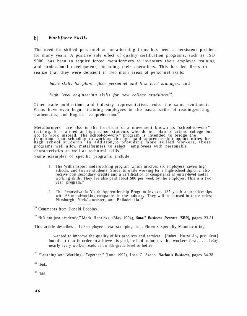
b) Workforce Skills
The need for skilled personnel at metalforming firms has been a persistent problemfor many years. A positive side effect of quality certification programs, such as ISO9000, has been to require forced metalformers to inventory their employee trainingand professional development, including their operations. This has led firms torealize that they were deficient in two main areas of personnel skills:
basic skills for plant floor personnel and first level managers and
high level engineering skills for new college graduates26.
Other trade publications and industryFirms have even begun training employees in the basics skills of reading,writing,
representatives voice the same sentiment.
mathematics, and English comprehension.27
Metalformers are also in the fore-front of a movement known as “school-to-work”traimng. It is armed at high school students who do not plan to attend college butgot to work instead. The school-to-work” program is intended to bridge thetransition from schooling to working through paid apprenticeship opportunities for high school students. In addition,to providing more skilled workers, these programs well allow metalformers to select employees with personablecharacteristics as well as technical skills.28
Some examples of specific programs include:
1. The Williamsport metalworking program which involves six employers, seven highschools, and twelve students. Students while working for a high-school diploma alsoreceive post secondary credits and a certification of competence in entry-level metalworking skills. They are also paid about $80 per week by the employer. This is a twoyear program.”
2. The Pennsylvania Youth Apprenticeship Program involves 135 youth apprenticeshipswith 66 metalworking companies in the industry. They will be focused in three cities:Pittsburgh, York/Lancaster, and Philadelphia.“’
26 Comments from Donald Dobbins.
27 “It’s not just academic,” Mark Henricks, (May 1994), Small Business Reports (SBR), pages 23-31.
This article describes a 120 employee metal stamping firm, Phoenix Specialty Manufacturing:
. . . wanted to improve the quality of his products and services. [Robert Hurst Jr., president]found out that in order to achieve his goal, he had to improve his workers first. . . . Todaynearly every worker reads at an 8th-grade level or better.
28 “Learning and Working-- Together,” (June 1992), Joan C. Szabo, Nation’s Business, pages 34-38.
29 Ibid..
30 Ibid.
4 6

3. “Craftsmanship 2000” is a four year program based in Tulsa, Oklahoma. It is sponsoredby industry and the Tulsa Public Schools, the Tulsa County Area Vo-Tech trainingschools, Tulsa Junior College, and the Metropolitan Tulsa Chamber of Commerce.Fifteen high-school juniors will participate. Students will attend academic classes,technical training and on-site training and experience while earning $4.25 per hour.“’
4. Macomb Community College in suburban Detroit, Michigan began a cooperativeeducation program in 1989. It involves 100 students in a variety of industries includingmetalworking. Students work for two years toward an associates degree while workingin industry for six months.”
8. Competitive Issues
a) Competition Among Shops
T h e m e t a l f o r m i n g i n d u s t r y i s a m a t u r e i n d u s t r y m a k i n g p r o d u c t s t h a t a r e b a s i c a l l yc o m m o d i t i e s a f f e c t e d b y s t e e l p r i c e s ( r a w m a t e r i a l ) a n d p r o d u c t i o n c o s t s( m a n u f a c t u r i n g p r o c e s s ) . S i n c e f i r m s p a y b a s i c a l l y t h e s a m e p r i c e s f o r s t e e l ,p r o d u c t i o n b e c o m e s t h e s o u r c e o f m o s t c o m p e t i t i v e a d v a n t a g e .
N e w b u s i n e s s i s w o n t h r o u g h c l o s e d b i d s . T h e p r o c e s s i s s u m m a r i z e d b e l o w :
Requests for quotes (RFQ) for formed metal parts are sent out to f ive or s ixm e t a l f o r m e r s k n o w n t o a b u y e r a s p r o v i d e r s o f a s p e c i f i c t y p e o f p a r t .
The quote i s rece ived by the metal former and an est imate i s made on the too l ingc o s t o f t h e p a r t . T o o l i n g i s u s u a l l y p a i d f o r b y t h e c u s t o m e r , b u t c o m p e t i t i o n i sf i e r c e o n t o o l i n g c o s t s . S o m e t i m e s a c o n t r a c t s t a m p e r i s r e q u i r e d t o c a r r y t h ee x p e n s e o f t h e t o o l i n g u n t i l t h e p r o d u c t i o n a c t u a l l y b e g i n s .year . S ince the cost o f too l ing can reach $500 ,000 the problem is ser ious when cashf l o w i s t i g h t .
O n c e t o o l c o s t s a r e e s t i m a t e d , m a c h i n e c a p a c i t y a n d p r e s s t i m e a r e d e t e r m i n e d .The size of a part; its shape, and the thickness of the material to be formed alldetermine the s ize o f the presses required to form i t .S t a m p i n g f i r m s l o o k f o r t h es m a l l e s t p r e s s p o s s i b l e t o p r o d u c e t h e p a r t s t o k e e p t h e p e r - p i e c e c o s t s l o w .part icular press i s under-ut i l i zed i t may be used for a job just to keep i t working .
A r e s p o n s e t o t h e b u y e r i s s u b m i t t e d o n t h e p a r t . M a n y c o m p a n i e s e x p e r i e n c e v e r yt o u g h b i d d i n g o n p r o d u c t s t h a t a r e c o n s i d e r e d b a s i c c o m m o d i t i e s , s u c h a s b r a c k e t s .Contract stampers suggest that it is not unusual for major customers to receive bidson a part then resubmit the request if they think they can do better.
31 Ibid.
47

contract firms have poor knowledge of their capacity and their costs; therefore,many jobs can be money losers for contract stampers.
The percentage of successful response bids to quotes varies due to the fact thatcaptive firms have a very high hit ratio, while contract firms must quote on a lotmore RFQs to win jobs.
According to the Performance Benchmarking Service, a current 62 metalformingmember panel, shows a spread of responses:
While discussions with marketing managers of contract firms indicates that an‘acceptable’ hit rate on quotes is about 10%, the responses in Table 21 indicate thatsuch a hit-rate falls slightly below median-performance. The highest performingcompanies have between 45% to 72% hit-rates on quotes, while the lowestperforming companies experience between 5.4% to 10% success on quotes. Whilethe average shop perceives competing quotes to number about 3, the bestperformers perceive 10 competing shops quoting against them on jobs.
To increase the competitive position of bids many firms offer additional services andprocesses to differentiate themselves from the commodity parts suppliers. Only oneout of ten firms supplying automotive companies with parts supply only stamped orblanked parts. Most firms offer sophisticated engineering services to assistcustomers in engineering activities. Many ancillary processes are also provided.Some of the most common ancillary process capabilities offered by firms supplyingthe automotive industry are:
Tool building GrindingWelding FinishingAssembly Hardening and heat-treatingPainting PlatingMachining Turning
b) Alternative Materials and Processes
Metalforming is a mature industry that is constantly under attack from alternativematerials and processes. The biggest reasons for replacing metalformed parts areusually based on reducing part costs, tooling costs, or weight of the part. On theother hand, metalformers aggressively seek out parts manufactured through otherprocesses, such as die castings that may be open for substitution. Conversationswith metal stamping executives indicate that metalforming has moved acrossdifferent products as components, but in general maintained its volumes.
4 8

Lower volumes on jobs (under 20,000 pieces) and simpler shapes are morevulnerable to process substitution than high volume complex shapes. Cutting partsout of sheet metal using a laser beam or plasma arc are common substitutions.Parts are simple, such as a flat panel. Many times cutting still requires a secondoperation, such as bending edges using press brakes. For buyers, cutting offers thesignificant advantage of zero tooling costs. The set up of the laser or plasma arccutting tables is done quickly on a computer, The downside of the substitution isthe cutting process is much slower therefore the per-piece cost is higher. Thequality is also not as good as a formed part since the cutting process can leaverougher edges than stampings. Many stampers maintain this technology on-site tooffer some horizontal integration and to counter any competitive advantage anotherfirm may have.
Material substitutions do not occur at the time of bid, but are usually researched fora great deal of time before the change is made. Making parts out of plastic orpowdered metal are common attempts.
However, steel stampings are holding their own due to improved grades of steel andimproved quality from stampers. By 1993 some of the products that were switchedto plastic and that are now returning back to stamped steel include: fuel tanks,fenders, pick up truck cargo boxes, roofs, and hoods.” This is expected to increasein the coming year due to new and expanding uses of steel.” Other more hightechnology approaches under experimentation include: hydroforming, super plasticforming, bulging, and exploding metal in closed dies.
9. Strategic Relationships and Requirements
a) Customer Perspectives
Automotive stamping has gone through some major restructuring over the lastfifteen years because automotive OEMs have restructured the supplier base. In the1980s, the concept of “tiered” suppliers was initiated. A tiered supplier basereduces the number of suppliers an OEM directly engages. Firms selling productdirectly to the OEM must be certified on quality, engineering, technical, and otherabilities. These are “First tier” suppliers. The supply chain looks like:
OEM Automotive <= First-Tier <= Second-Tier <= Third-Tier Suppliers
Of the automotive stamping firms, 413 are considered “First-tier” suppliers, orcompanies that directly supply their product to the OEM35. The remaining 205firms are Second and Third-tier suppliers; they provide components and stampingsto the higher ranked suppliers who in turn sell “systems” to OEMs.
33 US Industrial Outlook. 1994., US Department of Commerce.
34 Ibid..
35 Discussion with editor of the The ELM Guide to US Automotive Sourcing, (1994), 5th Edition.
49

First-tier suppliers have long term relationships with the major companies sincethey have considerable investments and personnel dedicated to stringent qualitystandards required to be certified, equipment and know-how on electronic datainterchange (EDI), and top level engineering services for the OEM’s products.
While very few firms have indicated that tiering requirements have cost them anybusiness36, firms try to achieve and maintain a high tier position to reducecompetition, maintain longer working relationships, and enjoy the prestige andadditional work that accompanies high tier certification. Plaques, flags andbanners are prominently displayed at many stamping firms as a symbol of theirdedication to excellence. Reduction in the supplier base is a major threat to thecontract stampers37, and some insiders indicate that only those firms doing at least$100 million in annual sales to OEMs will remain tier-one38.
b) Business Growth, Positioning, and Strategy
(1) BUSINESS GROWTHAverage growth rate in sales for metalformers, over the next five years, is expectedto reach 19.5%. Of this overall growth, 12% is expected to come from newcustomers while 13% will come from new products.39 The three top factors leadingto loss of business to contract metal stampers, over the last two years have been40:
l Pricel Product obsolescencel Reduction of the supplier base
Cost reductions by automotive OEMs have required suppliers to reduce prices by10%. New product developments have led to replacement of business; those firmsthat innovate have continued to do well. As major customers continue toconsolidate their supplier base, suppliers who did not meet quality requirementshave experienced loss of jobs, *while those who have met or exceeded requirementshave seen increased business. Performance Benchmarking data indicates that for
36 “Spotlight on PMA: A Look at Metalforming Markets,” (October 1994), Metal Forming, page 89.
37 Ibid.
38 ELM Guide to US Automotive Sourcing, 5th Edition. ELM International, Inc. East Lansing, MI48826, page II.
39 “Spotlight on PMA: A Look at Metalforming Markets,” (October 1994), Metal Forming, page 89.
40 Ibid.
50

metalformers with plants at least 5 years old, 77% experienced a change in sales;the top performers attribute 35% of sales to customers not served three years ago41.
(2) POSITIONING
Performance Benchmarking data of 63 metalformers42 shows that companies tend toposition their formed products by offering unique or ‘proprietary’ products,‘specialized,’ processing capabilities, and/or shipment of assemblies rather thanparts. Table 22 below shows percent of sales by type of product positioning.
The top performer’s sales are mostly from unique products and processes, or fromassembly. Low performance is associated with ‘commodity’ ‘parts’ production.
Table 23, below, illustrates metalforming companies responsibility for building diesand/or tooling and the percent of sales accounted by such jobs.
Clearly, designing and building dies and tooling are process capabilities which havemajor rewards. Metalforming firms can benefit by developing capabilities andoffering these to customers. The best performers position themselves to offerintegrated service and job capabilities.
(3) STRATEGY
Metalforming companies whose management spends little or no time in developingstrategies usually fare the worst. On an average, managers spent 50 hours in
41 Metalforming Sector Performance Benchmarking Report , (1995), Industrial Technology Institute,Ann Arbor, MI.42 Ibid.
5 1

developing strategy over the last year43. Ten percent of company managers spent atleast 250 hours, while a quarter of the industry’s managers spent 2.6 hours or less.
C) Sales and Marketing
The typical metalformer’s sales and marketing activities include using outside salesforce, manufacturers representatives, and inside sales (dedicated employees).Inside sales has been found to be the most common approach. Table 24, below,illustrates metalforming companies’ sales methods.
Table 24: Sales Methods Used by MetalformersSales Method Firms Using Method (%)Inside sales force and manufacturers representatives: I
! 75%Company executives:Joint sales with engineering support staff: I
Outside sales only: II
Source: Metal Forming, October 1994, page 89.
69%56%55%
Marketing activities have commonly used advertisements as the preferred mode ofpromoting products and company capabilities. Table 25, below, shows the variousmarketing and promotion activities metalformers use.
d) Supplier Perspectives
A persistent issue faced by contract metalformers is the fluctuating price of steel,the principle raw material for formed products and a high percentage of their coststructure.
Metalformers are many times squeezed on both sides. On the one hand, somecustomers demand that they hold the price lines or actually reduce it. On the otherhand, steel suppliers set prices that are not controlled by metalformers, as pricesare based on the mill’s capacity, imports, exports, and other issues. Because price isa critical factor in gaining or losing business, the ups and downs in steel pricesgreatly affects the fortunes of metalformers.
Metalformers offset this problem through a few methods. First, they may offer anintegrated service that includes design and other value-added, such as finishing orassembly in order to reduce the ratio of material cost to overall cost of the job.
43 Ibid.
52
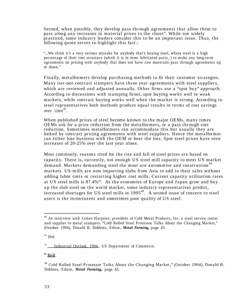
Second, when possible, they develop pass through agreements that allow them topass along any increases in material prices to the client”. While not widelypracticed, some industry leaders consider this to be an important issue. Thus, thefollowing quote serves to highlight this fact.:
“...We think it’s a very serious mistake for anybody that’s buying steel, where steel is a highpercentage of their cost structure (which it is in most fabricated parts, ) to make any long-termagreements on pricing with anybody that does not have raw materials pass through agreements upor down.”
Finally, metalformers develop purchasing methods to fit their customer strategies.Many tier-one contract stampers have three year agreements with steel suppliers,which are reviewed and adjusted annually. Other firms use a “spot buy” approach.According to discussions with stamping firms, spot buying works well in weakmarkets, while contract buying works well when the market is strong. According tosteel representatives both methods produce equal results in terms of cost savingsover time45.
When published prices of steel become known to the major OEMs, many timesOEMs ask for a price reduction from the metalformers, or a pass through costreduction. Sometimes metalformers can accommodate this but usually they arelocked by contract pricing agreements with steel suppliers. Hence the metalformercan either lose business with the OEM or bear the loss. Spot steel prices have seenincreases of 20-25% over the last year alone.
Most commonly, reasons cited for the rise and fall of steel prices are based oncapacity. There is, currently, not enough US steel mill capacity to meet US marketdemand. Markets demanding steel the most are automotive and construction40
markets. US mills are now importing slabs from Asia to add to their sales withoutadding labor costs or restarting higher cost mills. Current capacity utilization ratesat US steel mills is 87.4%“‘. As the economies of Europe and Japan grow and buyup the slab steel on the world market, some industry representatives predict,increased shortages for US steel mills in 199548. A second issue of concern to steelusers is the inconsistent and sometimes poor quality of US steel.
44 An interview with James Harpster, president of Cold Metal Products, Inc. a steel service centerand supplier to metal stampers. “Cold Rolled Steel Processor Talks About the Changing Market,”(October 1994), Donald B. Dobbins, Editor, Metal Forming, page 45.
45 Ibid
46 Industrial Outlook. 1994., US Department of Commerce.
48 Cold Rolled Steel Processor Talks About the Changing Market,” (October 1994), Donald B.Dobbins, Editor, Metal Forming,. page 45.
53

e) Quality Requirements
Quality ratings are slightly different for each automotive OEM; the ratings aresummarized below:
QS 9000
QS 9000, a new quality requirement standard, was developed by a task force thatincluded:
l Chryslerl Fordl General Motorsl Supplier Advisory Councill AIAG Truck Advisory GroupInternational Organization for Standardization
54
The purpose of QS 9000 is to:
Replace redundant quality management systems used in automotive and truckindustries,
Provide a comprehensive structure for quality systems, and
Provide a model for quality management systems for internal and externalassessments.
The general goals of QS 9000 are to foster continues improvement, eliminatedefects, reduce variation, reduce waste and improve customer satisfaction.Manufacturers who want to comply with the QS 9000 standards must register withan accredited auditor. The manufacturer must maintain a quality system whichincludes a detailed manual that describes and explains quality procedures withproof that these procedures have been followed. The QS 9000 compliant firm isinspected and audited no less than once every three years.
Most metalformers that primarily do business with the automotive industry havesmall customer bases. This may mean fewer than ten significant clients. Based ondiscussions with core management at metalforming firms, these customers areusually big firms, either automotive OEMs or first-tier suppliers to the OEMs.Because these large customers have production all over the world they arepressuring important suppliers to open production overseas or find a way to supplythe OEM overseas. Because these customers are critically important tometalformers, they are doing everything to become international suppliers. Thesechanges include adopting international certification of quality standards, such asIS0 9000. They are opening offices overseas and hiring sales and marketing staffwith international experience. Firms with financial and managerial strength willsurvive industry changes. This scenario is voiced by ELM International, Inc.:
“[Ford] has announced that it will continue to trim its supplier base and that preference will begiven to those suppliers that build facilities in locations where Ford has assembly operations. Onthe one hand, Ford is giving suppliers the opportunity to supply its world wide operations, while onthe other hand, the cost of entry will require the suppliers to locate facilities in many differentcountries. This does not necessarily mean that the facilities have to be 100% owned and operatedby the supplier. They could be joint ventures or technology tie-ups. It is likely that the otherautomakers will follow Fords lead, at least in part.“”
f) Government and Regulations
The US government affects the metalforming industry through two primaryagencies: the US Environmental Protection Agency (USEPA) and the OccupationalSafety and Health Administration (OSHA) of the Department of Labor. Other
4 9
ELM Guide to US Automotive Sourcing, 5th Edition. ELM International, Inc. East Lansing, MI48826, page II.
55

departments are less direct such as Department of Commerce, Department ofTransportation, and the Department of Labor (Immigration).
The table below, Table 27, introduces regulatory acts and terminology commonlyused in the environmental context”“:
The effect regulations have on metalformers depends in large part as to thegeographic location of the establishment. Firms in Florida, Southern California,and Texas are affected by immigration regulations and law, while firms inCalifornia, Wisconsin, and New Jersey are affected by local variations of USEPAregulations or by regional regulations. Regulations by agency affectingmetalformers are briefly summarized below:
(1) USEPAMetalformers are affected by regulations from four USEPA initiatives:
Emergency Planning and Community Right-to-know Act (EPCRA)Resources Conservation and Recovery Act (RCRA)- scrap and used oilClean Air Act (CAA) - Title 5, ODC LabelingClean Water Act (CWA) - Storm water discharge, effluent guidelines
50 “Environmental Compliance: Managing the Mandates,” , (March 1995), Jean V. Owen, SeniorEditor, Manufacturing Engineering, page 59.
56
Most of the small to mid-sized metalformers (which make up the bulk ofmetalformers) do not designate a specific person to report on USEPA regulations.Usually, metalformers have no formal training on regulatory issues. This cannegatively impact business, according to industry representatives. Some issuesidentified are:
1.
2.
3.
4.
5.
Smaller and mid-sized firms are now refusing to purchase process chemicals such aslubricants or solvents that have any associated regulations. The burden anduncertainty of reporting to USEPA is too much so they try to avoid using thesechemicals.
Metalformers, currently, receive the bulk of information on process chemicals and toxicrelease regulations from product or service vendors because “they explain it in terms Ican understand”. However, even though relationships with vendors may go back forgenerations, the objectivity of the information is not always certain.
Metalformers complain that there is no resource on regulations that can be used by non-technical, non-scientific personnel usually assigned the task of reporting. Consequentlymany reports are incorrectly completed.
Some regulations from USEPA are perceived to have the potential to cost metalformersbusiness. According to the PMA., 20-30% of its members report the potential for loss ofbusiness due to switching from halogenated solvents to aqueous cleaning methods.Metalformers attribute this to products not properly cleaned with aqueous methods,especially small, deep-drawn parts such as metal pen casings or other deep-drawn tubescommon in medical applications.
Many metalformers are concerned with the potential for violating a USEPA regulationthat can cost thousands of dollars in fines and rework as well as lost time. For example,switching a drying process from electricity to natural gas can violate a Clean Air Actregulation requiring a permit”.
(2) OSHAOSHA requirements, while a larger issue for the industry, may be definitely lesstroubling. Although OSHA regulations and reports are considered a burden thereis less uncertainty about compliance. As with USEPA duties, OSHA activities arehandled by untrained staff. For this reason, reports are not properly filled out
Generally, metalformers consider safety and health as very important in theirestablishments. A recent survey conducted by the NIST/Michigan ManufacturingTechnology Center among metalformers indicated that safety was a significantissue. Concern for employees, as well as liability and insurance rates, areimportant motivators. However, metalformers consider OSHA regulations ashaving increased in recent years without necessarily improving safety or health ofworkers in plants.
61 As experienced by one metalformer interviewed.
57

(3) DEPARTMENT OF TRANSPORTATIONWhile, regulations on transporting hazardous wastes is not a major burden for theaverage metalformer, it does affect the larger metalforming firms.
(4) DEPARTMENT OF COMMERCETrade laws and the North American Free Trade Agreement (NAFTA) have requiredmore paperwork at metalforming establishments
Trade laws are a major problem for metalformers because of the tremendousdisparity in laws and regulations from one state to another. For instance,metalformers in California consider themselves at a distinct competitivedisadvantage due to strict environmental regulations. Because of the changes anddifferences in local regulations, national trade groups, such as PMA recommend its’members consult with local environmental experts to determine response toenvironmental issues.
Increased uncertainty can result if consultants are not formally certified orlicensed. Hence, metalformers need access to qualified and experienced industryconsultants.
10. Technology Trends
a) Manufacturing Technology Outlook:
Over the past five years, manufacturers have invested heavily in computer-aideddesign (CAD), data collection, planing and scheduling, and materials requirementplanning systems technologies. Table 28, below, shows technology areas thatmanufacturers intend to invest in over the next two to three years.
Table 28: Manufacturing Technology Investment Area52
Technology Investment Expected Percent ResponsePlanning and Scheduling 34.1%Data CollectionComputer-aided design
32.8%28.1%
Flexible Manufacturing 21.7%Electronic Data Interchange 20.7%Manufacturing Execution Systems 20.3%Statistical Process Control 19.8%Material Requirements Planning/MRP II 19.2%Material Handling Systems 18.1%Environmental Systems 11.9%
Clearly, planning systems lead as investment areas while environmental systemsinvestments are least anticipated. However, greater than 10% investment isanticipated for each of the technology areas, with small variance between the lower
52 “These are the Good Old Days,” (March 1995), Donald Davis, Associate Editor, ManufucturingSystems, page 38.
58

and greater responses. In addition, than 70% of the 643 respondents of aManufacturing Systems survey53 expect their companies to add production capacity.Nearly 44% expect an expansion of at least 25%. In general, companies can beexpected to upgrade facilities and improve operations in the future.
b) Advances and Near-Term Changes:
Advances in technological applications and technology use are being seen fromimproved raw material properties through manufacturing processes throughout thesupply chain from supplier to manufacturer to end-product user industries.
Significant advances and near term changes are anticipated in the following:
(1) RAW MATERIAL IMPROVEMENTS
Improvements in steel product are a result of massive improvements made in theUS steel mills in the 1980s and early 1990s. Production technology such as thin-slab casting ‘at Nucor Corporation, the nation’s largest steel mill, have keptproduction costs at US mills low and has helped maintain international qualitylevels54. Mills have developed bake-hardenable grades, lighter weight products, andhigh-strength steels. Nevertheless, significant steel quality problems remain.
(2) PROCESS TRENDS
The trend in press technology is towards unmanned, high speed production.Metalformers are expected to continue investing in transfer presses, hybrids, andprocess automation, such as press loaders and automated die changers to improveproduction efficiencies and competitive positions. To reduce raw material costs,new methods are being developed at Ohio State University (OSU) in the area offormability testing. OSU has developed an inexpensive machine which allowsestablishments the ability to test how a sheet material behaves in a press. Thismay help metalformers model the particular forming process with materialsubstitutions while avoiding failures in the forming process such as wrinkling orsplitting55.
( 3 ) MONITORING AND CONTROL
Quality control improvements are directed toward in process monitoring. This is inkeeping with the trend toward unmanned processes. Improvements in monitoringare also improving other areas of importance such as increased life of machineryand dies, reduced scrap, and increased safety of press operators. Gaugingtechnology has seen significant improvements. Coordinate Measurement Machines(CMM) are very common for extremely high precision measurements. These
63 Ibid.54 US Industrial Outlook. 1994., US Department of Commerce.
55 “An Affordable Sheet Formability Test System,” (October 1994), S.Sriram and R.H. Wagoner,.Metal Forming,. page 63-68.
59

devices continue to improve through higher speed gauging and the use of non-contact technology such as lasers.
(4) COMMUNICATIONS
All Tier-one suppliers of automotive OEMs and of other markets as well nowcommunicate their business documentation such as shipping notices, purchaseorders, acknowledgments, invoices, payments, CAD drawings, and RFQs throughElectronic Data Interchange (EDI) protocols. EDI is a standard for facilitatingcomputer-to-computer communication of important business and technicalinformation. This technology is being driven by production strategies such as Just-In-Time manufacturing in which timely release of orders is extremely important tothe precise delivery of goods. There are problems, however, especially for supplierswho must cope with differing standards in CAD drawings from different customers,but these differences are expected to be reduced over time with standardization.
(5) DESIGN
CAD has profoundly affected the stamping industry and continues to do so as CADworkstation technology improves. Design-time has shortened through the use ofCAD and become more complex as CAD offers designers more flexibility.
CAD drawings can be directly used by computerized numerical control (CNC)machines suitably linked and setup for computer aided manufacturing (CAM).
Product Data management systems that centralize engineering data and drawingsin an accessible database are expected to reduce design time as well.
(6) DATA COLLECTION
Bar codes are being increasingly used to capture and organize data efficiently andquickly with minimum human intervention and inefficiency.
(7) Other Technology Trends
Quality tooling is essential to achieve Statistical Process Control, Quick ChangeTooling, Just-In-Time deliveries, and Ship-to-Stock requirements of most majorcustomers56.
Concurrent engineering (design, development, and building of tooling) which helpsto achieve shortened deliveries of tooling is increasingly a requirement.
56 Changes in the Metal Stamping Industry,” (April 1995), Larry Crainich, Metal Forming, page 76.
60

D. Data Tables and Reference Resources
1. Geographic Distribution Data
Table D-l: Sheet Metal Work Firms Geographic DistributionGEOGRAPHIC DISTRIBUTION OF SIC 3444: SHEET METAL WORK
($ MM) ($ MM)
STATE #COs RAN-K T.EMP. E.RANK T.SALES S.RANK AVG.EMP. AVG.SLS.
California 1138Texas 587New York 470Pennsylvania 375Michigan 373Ohio 359Florida 328Illinois 318New Jersey 291Massachusetts 289Indiana 188Minnesota 167Washington 162North Carolina 161Georgia 160Wisconsin 150Connecticut 136Oregon 134Missouri 130Arizona 125Virginia 119Colorado 114Tennessee 112Maryland 105Alabama 91Kansas. 85Oklahoma 83Kentucky 76South Carolina 76Iowa 67New Hampshire 65Arkansas 62Utah 56Louisiana 46Mississippi 39Idaho 39Nevada 34Rhode Island 33Maine 31New Mexico 26West Virginia 23
1 19958 1 2333.4 4 19 2.32 11021 3 2958.6 3 20 6.13 9726 4 3657.6 2 22 8.84 7760 6 1779.8 5 22 5.65 6544 8 1155.2 11 19 3.66 12080 2 4574.8 1 35 14.87 5031 12 496.1 17 16 1.78 8562 5 1358.2 10 28 4.99 6016 9 1560.6 8 22 5.910 4939 13 780.3 14 18 2.911 6572 7 836.7 13 36 5.1
12 4926 14 936.8 12 30 6.2
13 2863 18 311.3 19 19 2.214 3998 15 542.0 16 25 3.915 3014 17 218.8 22 19 1.616 5838 10 1387.5 9 41 10.7
17 1904 25 266.8 21 16 2.418 1749 26 182.6 27 13 1.519 5556 11 1669.1 6 45 16.020 2360 21 457.5 18 21 4.321 3088 16 183.2 26 28 1.8
22 2020 24 184.1 24 20 1.923 2608 19 1630.2 7 25 17.3
24 2034 23 184.1 25 21 2.025 2130 22 86.5 35 23 1.0‘26 2586 20 212.1 23 33 3.227 1420 30 107.7 33 18 1.428 1642 27 176.3 28 21 2.629 1552 29 277.1 20 22 4.130 1625 28 155.2 31 24 2.731 974 34 74.6 36 17 1.3
32 1226 33 128.4 32 20 2.233 1316 31 168.2 29 24 3.334 387 39 34.1 41 9 0.835 1239 32 157.7 30 33 5.8
36 609 38 47.4 40 16 1.337 727 37 53.0 39 23 1.838 224 43 756.4 15 8 29.039 738 36 88.7 34 26 3.140 155 45 13.1 44 5 0.541 857 35 57.5 38 37 3.1
61

STATE RCOs RAN5 T.EMP. E.RANK T.SALES S.RANK AVG.EMP. AVG.SLS.
Nebraska 22 42 350 41 19.7 42 16 1.0Hawaii 19 43 361 40 62.7 37 25 6.2Delaware 19 44 283 42 18.8 43 15 1.1Montana 11 45 81 46 2.0 48 8 0.2Vermont 10 46 192 44 11.9 45 21 1.4North Dakota 10 47 37 50 1.6 49 6 0.3Alaska 9 48 58 47 5.0 47 6 0.7Wyoming 7 49 43 49 1.6 50 8 0.3South Dakota 6 ’ 50 51 48 6.6 46 10 1.3Washington, DC 2 51 15 51 0.6 51 7 0.6
Totals/Averages 7538 161045 32369.8 23
Source: 1995 Jan-Mar MarketPlace Business Software (Dunn and Bradstreet)
5.0
62

STATE #COs RANK T.EMP. E.RANK T.SALES S.RANK AVG.EMP. AVG.SLS.Mississippi 8 16 936 13 56.5 18 117 28.2Texas 8 17 82 27 6.8 25 13 1.1New Jersey 7 18 951 12 1359.0 4 135 194.1Iowa 7 19 504 19 8.2 23 72 2.7Washington 7 20 201 21 20.3 22 28 3.3New Hampshire 5 21 1056 10 1003.5 5 211 334.5Virginia 5 22 181 22 1.8 30 36 0.6Missouri 5 23 150 24 33.8 20 37 8.4Alabama 4 24 109 25 0.2 37 27 0.1Arizona 4 25 57 29 6.3 26 19 2.1Oklahoma 4 26 41 30 3.0 28 10 0.7North Carolina 4 27 17 33 1.1 31 4 0.3Oregon 4 28 16 34 2.8 29 4 0.7Massachusetts 3 29 77 28 7.7 24 25 2.5Kansas 3 30 28 32 0.9 32 9 0.4Arkansas 3 31 5 36 0.4 35 2 0.4West Virginia 2 32 554 17 88.1 14 277 44.0Maryland 2 33 370 20 77.7 15 185 38.8Colorado 2 34 36 31 5.0 27 18 2.5Utah 2 35 9 35 0.5 33 4 0.2Nebraska 1 36 100 26 NA 41 100 NALouisiana 1 37 5 37 0.3 36 5 0.3Maine 1 38 3 38 0.5 34 3 0.5Nevada 1 39 2 39 0.2 38 2 0.2Idaho 1 40 2 40 0.1 39 2 0.1Vermont 1 41 1 41 0.1 40 1 0.1
Totals/Advntages 889 124488 24953.7 150 38.0
Source: 1995 Jan-Mar Marketplace Business Software (Dunn and Bradstreet)
Table D-4: Largest Automotive Stampings Firms Geographic DistributionLARGEST COMPANIES (GREATER THAN 500 EMPLOYEES) BY STATE FOR SIC 3465
($ MM) ($ MM) STATE #COs RANK T.EMP. E.RANK T.SALES S.RANK AVG.EMP. AVG.SLS.Michigan 15 1 29175 1 120.2 6 1945 120.2Ohio 10 2 21123 2 244.7 4 2112 122.3Tennessee 4 3 2810 5 273.4 3 702 136.7Indiana 3 4 6700 3 NA 9 2233 NAIllinois 2 5 3600 . 4 199.1 5 1800 199.1New York 1 6 2400 6 NA 10 2400 NACalifornia 1 7 1000 7 393.0 2 1000 393.0Wisconsin 1 8 1000 8 50.0 8 1000 50.0N e w H a m p s h i r e 1 9 900 9 NA 11 900 NAConnecticut 1 10 700 10 NA 12 700 NANew Jersey 1 11 560 11 740.2 1 560 740.2West Virginia 1 12 551 12 88.0 7 551 88.0
b&/Averages 4 1 70519 2108.6 1719
Source: 1995 Jan-Mar MarketPlace Business Software (Dunn and Bradstreet)
210.8
63


STATE #COs RANK T.EMP. E.RANK T.SALES S.RANK AVG.EMP. AVG. SLS.Pennsylvania 240 7 11965 7 3276.0 3 51 16.1Connecticut 214 8 10574 8 1647.2 10 51 8.5Wisconsin 204 9 13797 3 2979.0 4 68 17.6Massachusetts 199 10 5079 13 485.5 14 26 2.5Indiana 179 11 8338 9 830.4 12 50 6.0Texas 162 12 2805 18 214.5 19 18 1.5Minnesota 140 13 7202 10 2242.3 8 53 17.6Florida 135 14 2309 19 168.3 23 19 1.6North Carolina 94 15 3069 16 434.7 16 35 5.7Missouri 92 16 4291 14 434.6 17 48 5.0Tennessee 87 17 6408 11 568.4 13 75 8.1Rhode Island 81 18 1973 22 194.9 21 25 2.5Georgia 68 19 3682 15 206.9 20 61 4.2Washington 52 20 1023 25 64.3 27 21 1.3Kentucky 49 21 2116 21 156.5 25 49 4.0Alabama 48 22 1152 24 162.7 24 26 4.5Iowa 45 23 2295 20 185.9 22 54 4.6Virginia 43 24 823 27 458.7 15 20 12.0New Hampshire 40 25 631 30 281.7 18 16 7.6South Carolina 38 26 2922 17 66.7 26 81 2.2Maryland 36 27 494 33 63.7 28 14 2.1Arkansas 34 28 875 26 52.2 31 25 1.7Kansas 33 29 631 31 35.6 33 21 1.3Colorado 33 30 537 32 62.7 29 16 1.9Arizona 31 31 1324 23 53.4 30 45 2.6Oklahoma 30 32 686 28 27.7 35 24 1.2Oregon 30 33 386 35 38.4 32 13 1.3Mississippi 28 34 640 29 31.0 34 22 1.2Utah 26 35 203 38 16.4 38 7 0.6Nevada 19 36 138 43 21.9 36 8 1.6New Mexico 11 37 430 34 5.0 44 43 0.5Louisiana 11 38 180 39 6.7 43 16 0.7Maine 11 39 161 40 11.4 40 14 1.0Vermont 11 40 108 44 7.1 42 12 0.8Nebraska 9. 41 150 41 16.3 39 16 2.0Delaware 9 42 77 45 1843.3 9 8 230.4Idaho 7 43 222 37 1.6 47 37 0.3West Virginia 6 44 42 47 2.9 46 7 0.4South Dakota 4 45 63 46 3.8 45 15 1.2Wyoming 3 46 276 . 36 17.8 37 92 8.9North Dakota 3 47 139 42 10.2 41 46 3.4Montana 2 48 32 48 0.4 49 16 0.4Hawaii 2 49 13 49 0.9 48 6 0.4
Totals/Averages 5224 190596 36120.5 38
Source: 1995 Jan-Mar MarketPlace Business Software (Dunn and Bradstreet)
8.0
65

Table D-8: Largest Metal Stampings Firms Geographic Distribution‘LARGEST COMPANIES (GREATER THAN 500 EMPLOYEES) BY STATE FOR SIC 3469STATE ICOs RANK T.EMP. E.RAN-K T.SALES S.RANK AVG.EMP. AVG.SLS.
Wisconsin 5 1 4500 1 1634.5 2 900 326.9
New York 4 2 3570 2 1639.2 1 892
Pennsylvania 3 3 3175 3 66.3 8 1058
Illinois 3 4 2700 4 792.4 4 900
Michigan 3 5 1905 8 NA 10 635Tennessee 2 6 2550 5 200.0 5 1275Ohio 2 7 2350 6 850.0 3 1175Connecticut 2 8 2000 7 97.5 6 1000
South Carolina 2 9 1764 10 NA 12 882Minnesota 1 10 1800 9 NA 11 1800California 1 11 600 11 90.0 7 600
Missouri 1 12 550 12 42.7 9 550
Iowa 1 13 500 13 NA 13 500Totals/Averages 30 27964 5412.6 932
Source: 1995 Jan-Mar Marketplace Business Software (Dunn and Bradstreet)
409.866.3
396.2NA
200.0425.097.5NANA90.042.7NA
300.7
Table D-9: Misc. Fab.Metal Products Firms Geographic DistributionGEOGRAPHIC DISTRIBUTION OF SIC 3499: MISC. FABRICATED METAL PRODUCTSSTATE #COs RANK T.EMP. E.RANK T.SALES S.RANK AVG.EMP. AVG.SLS.
CaliforniaNew YorkIIlinoisOhioTexasPennsylvaniaFloridaMichiganIndianaNew JerseyMassachusettsNorth CarolinaWisconsinMinnesotaConnecticutGeorgiaMissouriRhode IslandOregonVirginiaTennesseeWashingtonArizonaColoradoArkansasMarylandKentuckyOklahoma
351 1 6242 3 710.6 8 17 2.1195 2 5556 4 1176.1 3 28 6.5164 3 6617 1 5167.3 1 41 3 4 . 4156 4 6518 2 1852.6 2 43 14.0151 5 2688 9 350.4 13 18 2.5116 6 5307 5 1056.9 6 46 10.4114 7 2489 10 1140.5 5 22 11.0106 8 2839 8 401.2 12 27 4.489 9 4711 6 412.5 11 53 5.484 10 2359 11 988.6 7 29 13.074 11 2851 7 326.4 14 39 4.863 12 2318 12 71.3 26 36 1.363 13 1201 19 100.6 22 19 1.753 14 1723 14 219.9 16 33 4.653 15 1616 16 274.0 15 30 5.951 16 1170 21 465.8 10 23 10.845 17 1617 15 82.3 23 36 1.939 18 1029 23 74.1 25 28 2.039 19 263 38 23.4 32 6 0.638 20 2017 13 469.8 9 53 15.138 21 1296 18 149.5 18 36 4.336 22 621 26 163.6 17 17 4.832 23 472 29 26.8 30 15 0.932 24 293 36 22.2 33 9 0.729 25 895 24 21.7 36 31 0.927 26 270 37 43.3 28 10 1.926 27 1192 20 9.8 41 47 0.426 28 363 30 21.8 35 13 0.8
66

STATE # COs RANK T.EMP. E. RANK T.SALES S. RAN-K AVG. EMP. AVG. SLS.
Louisiana 21 29 306 33 22.0 34 15 1.2Alabama 21 30 186 40 11.2 40 9 0.6Utah 20 31 586 28 63.8 27 29 3.5Iowa 19 32 1357 17 109.0 21 75 7.2Kansas 19 33 302 35 13.9 39 15 0.8South Carolina 18 34 608 27 21.1 37 33 1.5New Mexico 16 35 303 34 24.1 31 20 1.6Mississippi 14 36 1063 22 78.0 24 75 6.0Nebraska 12 37 306 32 31.0 29 25 3.1Maine 12 38 186 39 16.0 38 15 1.3New Hampshire 9 39 121 42 1163.9 4 15 129.3Vermont 8 40 318 31 124.4 20 45 15.5Montana 8 41 99 43 7.2 42 12 0.9Idaho 8 42 39 46 2.1 46 4 0.3Hawaii 7 43 20 48 2.1 47 2 0.3West Virginia 6 44 125 41 3.8 45 20 0.9
South Dakota 6 45 78 44 1.4 48 13 0.2
Nevada 6 46 70 45 4.5 44 11 0.7Delaware 5 47 763 25 138.3 19 152 27.6Alaska 4 48 20 47 5.8 43 5 1.4North Dakota 3 49 19 49 1.2 49 6 0.4Wyoming 2 50 10 50 0.4 50 5 0.2
Washington, DC 2 51 7 51 0.4 51 3 0.2
JTotalsJAverages 2536 73425 17668.6 29 7.7
Source: 1995 Jan-Mar Marketplace Business Software (Dunn and Bradstreet)
Table D-10: Largest Fab. Metal Products Firms Geographic DistributionLARGEST COMPANIES (GREATER THAN 500 EMPLOYEES) BY STATE FOR SIC 3499
STATE #COs RAN-K T.EMP. E.RANK T.SALES S.RANK AVG.EMP. AVG.SLS.
New Jersey 1 6 1000 6 720.0 1 1000 720.0Ohio 1 7 900 7 623.2 2 900 623.2New York 3 3 1788 3 307.0 3 596 102.3Pennsylvania 3 1 2350 1 275.0 4 783 91.6Texas 1 ‘ 9 750 9 150.0 5 750 150.0California 1 4 1500 4 134.2 6 1500 134.2Delaware 1 11 700 11 134.0 7 700 134.0Tennessee 1 12 625 12 108.0 8 625 108.0Illinois 3 2 1800 2 106.0 9 600 53.0Iowa 1 5 1100. 5 91.1 10 1100 91.1Massachusetts 1 8 900 8 89.9 11 900 89.9Michigan 1 17 500 17 80.0 12 500 80.0Mississippi 1 10 750 10 63.6 13 750 63.6Florida 1 18 500 18 59.7 14 500 59.7Indiana 1 14 600 14 50.0 15 600 50.0Virginia 1 15 540 15 42.2 16 540 42.2Missouri 1 16 503 16 20.0 17 503 20.0Kentucky 1 13 600 13 NA 18 600 NATotals/Averages 24 17406 3053.9 725
Source: 1995 Jan-Mar MarketPlace Business Software (Dunn and Bradstreet)
138.8
67

2. US Metalforming Machinery In Use Data:
Table D-11: Sheet Metal Work Machinery In Use
SHEET METAL WORK SHOP FLOOR MACHINERY ENDOWMENT %
Machinery Type
Engine & Toolroom, including Bench, not Tracer,non-NC turning machines
Vertical Upright (Hand Or Power Feed),non-NC drilling machines
All Other Non-NC Drills (Incl Gun) (Exc Way Station),non-NC drilling machines
Vertical Spindle, Ram Type With Swivel Headnon-NC milling machines
General Purpose, Knee Or Bed: Vertical Or Horizontal,non-NC milling machines
Surface: Hand-Reciprocating Table,non-NC grinding machines
Bench, Floor, And Snag, non-NC grinding machinesAbrasive Belt (Except Finishing), non-NC grindingTapping machinesHacksaws
41%
57%
10%
41%
31%
Circular Cutoff Saws (Incl Cold Saws)Abrasive Wheel Cutoff and Sawing machinesBandsaw, Contour Sawing & Filing machinesNC Punching machinesPunching machines (Incl Comb Punch-Shear)Plate & Sheet ShearsPress Brakes: Mechanical, non-NC bending & forming
Other Miscellaneous (machinery less than 1% on shop floor)
Press Brakes: Hydraulic & PneumaticBending Rolls, non-NC bending & forming machinesOpen Back & Gap mechanical presses-power (not forge)Hydraulic Presses (not forge)Coil Processing SystemsAll Other Non-NC Metalforming machinesRiveting Machines (Not Portable)Manual Weld Equipment (No. Of Power Supplies)Semi-Automatic Welding machinesSpot And Seam, electric resistance-welding equipmentBarrel Finishing (Tumbling) machinesPainting SystemsComputer Workstations
100%
30%23%38%26%23%57%51%79%38%57%79%67%49%52%46%30%6%5%
33%85%20%75%33%20%44%
Percent Of Percent OnCompanies Typical Co.o w n i n g Shop Floor
2%
4%
4%
3%
1%
1%2%2%1%1%3%2%4%1%4%4%5%2%3%4%1%2%2%2%10%2%5%1%1%2%
20%
Source: 14th Inventory of Metalworking Equipment, American Machinist, 1989Developed by Market ScoutrM
68
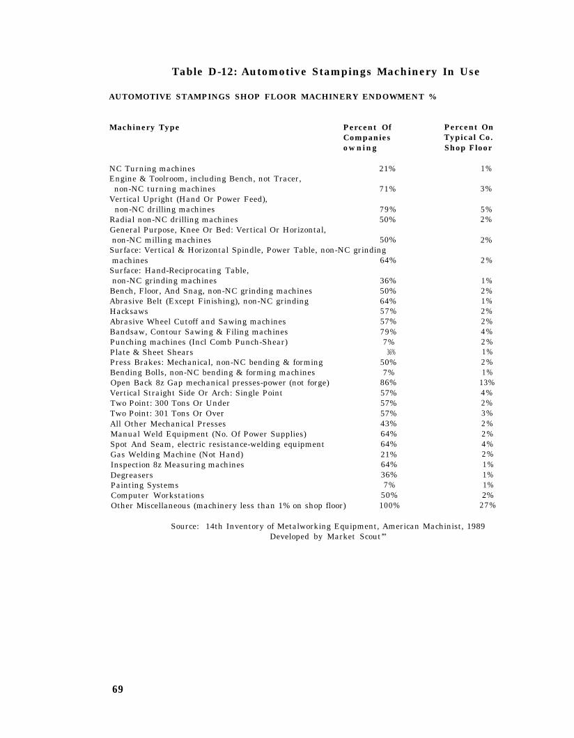
Table D-12: Automotive Stampings Machinery In Use
AUTOMOTIVE STAMPINGS SHOP FLOOR MACHINERY ENDOWMENT %
Machinery Type Percent Of Percent OnCompanies Typical Co.owning Shop Floor
NC Turning machines 21%Engine & Toolroom, including Bench, not Tracer,
non-NC turning machines 71%Vertical Upright (Hand Or Power Feed),
non-NC drilling machines 79%Radial non-NC drilling machines 50%General Purpose, Knee Or Bed: Vertical Or Horizontal,non-NC milling machines 50%
Surface: Vertical & Horizontal Spindle, Power Table, non-NC grindingmachines 64%
Surface: Hand-Reciprocating Table,non-NC grinding machines 36%
Bench, Floor, And Snag, non-NC grinding machines 50%Abrasive Belt (Except Finishing), non-NC grinding 64%Hacksaws 57%Abrasive Wheel Cutoff and Sawing machines 57%Bandsaw, Contour Sawing & Filing machines 79%Punching machines (Incl Comb Punch-Shear) 7%Plate & Sheet Shears 36%Press Brakes: Mechanical, non-NC bending & forming 50%Bending Bolls, non-NC bending & forming machines 7%Open Back 8z Gap mechanical presses-power (not forge) 86%Vertical Straight Side Or Arch: Single Point 57%Two Point: 300 Tons Or Under 57%Two Point: 301 Tons Or Over 57%All Other Mechanical Presses 43%Manual Weld Equipment (No. Of Power Supplies) 64%Spot And Seam, electric resistance-welding equipment 64%Gas Welding Machine (Not Hand) 21%Inspection 8z Measuring machines 64%Degreasers 36%Painting Systems 7%Computer Workstations 50%Other Miscellaneous (machinery less than 1% on shop floor) 100%
1%
3%
5%2%
2%
2%
1%2%1%2%2%4%2%1%2%1%
13%4%2%3%2%2%4%2%1%1%1%2%
27%
Source: 14th Inventory of Metalworking Equipment, American Machinist, 1989Developed by Market Scout’”
69

Table D-13: Crowns and Closures Machinery In Use
CROWNS AND CLOSURES SHOP FLOOR MACHINERY ENDOWMENT %
Machinery Type Percent Of Percent OnCompanies Typical Co.Owning Shop Floor
Engg. & Toolroom (Not Tracer) Up To & Including8-In Swing, Non-NC turning machines 67%
Engg. & Toolroom (Not Tracer) Over 8-In To 16-In Swing,Non-NC turning machines 67%Engg. h Toolroom (Not Tracer) Over 16-In ,Non-NC turning machines 44%
Vertical Upright (Hand Or Power Feed),non-NC drilling machines 56%
Vertical Spindle, Ram Type With Swivel Headnon-NC milling machines 56%General Purpose, Knee Or Bed: Vertical Or Horizontal,non-NC milling machines 44%
External: Plain Centertype, Non-NC grinding machines 44%External: Universal Centertype, Non-NC grinding machines 44%Surface: Vertical & Horizontal Spindle, Power Table, non-NC grindingmachines 44%
Bench, Floor, And Snag, non-NC grinding machines 78%Disk Grinders, Single & Double Spindle 22%Abrasive Belt (Except Finishing), non-NC grinding 33%Hacksaws 56%Circular Cutoff Saws (Incl Cold Saws) 33%Bandsaw, Contour Sawing & Filing machines 78%Punching machines (Incl Comb Punch-Shear) 11%I Non-NC bending & forming machines (power) 22%Open Back (Obi) C Gap: Up To 50 Tons, mechanical presses 78%Open Back (Obi) & Gap: 51 Tons & Over mechanical presses 22%Hydraulic Presses (not forge) 33%Thread Rolling Machines 33%Automatic Assembly machines (all types) 11%Non-Programmable Automatic Assembly Single Station machines 11%Manual Weld Equipment (No. Of Power Supplies) 89%Plastic-Injection Molding machines 22%Optical Comparators 67%Baking & Drying Ovens 67%Cleaning & Finishing equipment 33%Other Miscellaneous (machinery less than 1% on shop floor) 100%
5%
4%
2%
3%
3%
3%1%1%
1%4%1%1%1%1%3%3%1%
15%4%1%9%1%1%4%2%2%7%2%17%
Source: 13th Inventory of Metalworking Equipment, American Machinist, 1983Developed by Market ScoutTM
70

Table D-14: Metal Stampings Machinery In Use
METAL STAMPINGS SHOP FLOOR MACHINERY ENDOWMENT %
Machinery Type Percent Of Percent OnCompanies Typical Co.owning Shop Floor
Engine & Toolroom, including Bench, not Tracer,non-NC turning machines 76%
Turret Lathes (All non-NC) 17%Vertical Upright (Hand Or Power Feed),
non-NC drilling machines 76%NC Milling machines 24%Vertical Spindle, Ram ‘Type With Swivel Headnon-NC milling machines 65%General Purpose, Knee Or Bed: Vertical Or Horizontal,non-NC milling machines 47%Surface: Vertical & Horizontal Spindle, Power Table, non-NC grindingmachines 70%
Surface: Hand-Reciprocating Table,non-NC grinding machines 37%Bench, Floor, And Snag, non-NC grinding machines 37%Disk Grinders, Single & Double Spindle 28%Abrasive Belt (Except Finishing), non-NC grinding 50%Honing, Lapping, Polishing machines 30%Tapping machines 41%Circular Cutoff Saws (Incl Cold Saws) 36%Bandsaw, Contour Sawing & Filing machines 89%Punching machines (Incl Comb Punch-Shear) 18%Non-NC Bending & forming machines (power) 41%Open Back & Gap mechanical presses-power (not forge) 70%Vertical Straight Side Or Arch: Single Point 39%Two Point: 300 Tons Or Under 21%All Other Mechanical Presses 23%Hydraulic Presses (not forge) 36%Coil Processing Systems 12%Multiple-Slide Forming machines 10%Manual Weld Equipment (No. Of Power Supplies) 60%Spot And Seam, electric resistance-welding equipment 50%Optical Comparators 57%Barrel Finishing (Tumbling) machines 42%Vibratory Finishing Machines 41%Other Miscellaneous (machinery less than 1% on shop floor) 100%
5%1%
6%1%
4%
2%
4%
2%2%1%1%1%1%1%4%1%3%14%4%1%5%2%1%3%3%2%2%2%1%
20%
Source: 14th Inventory of Metalworking Equipment, American Machinist, 1989Developed by Market ScoutTM
71
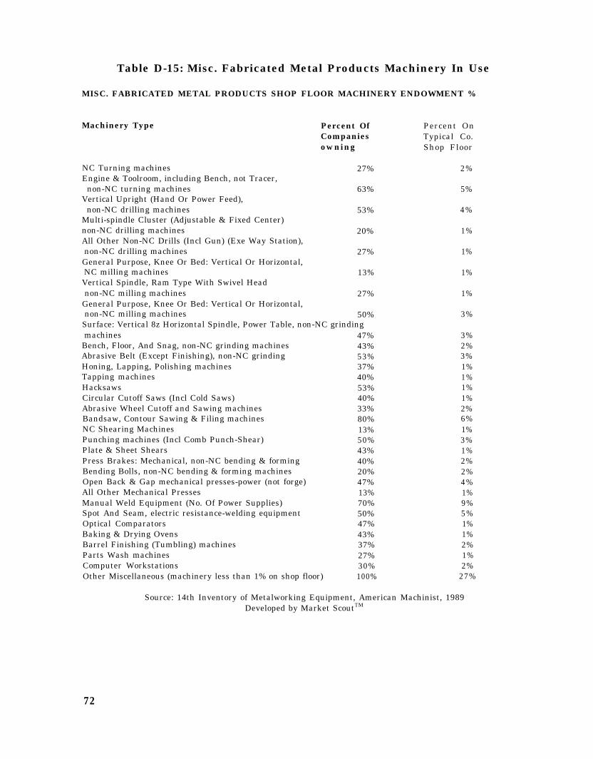
Table D-15: Misc. Fabricated Metal Products Machinery In Use
MISC. FABRICATED METAL PRODUCTS SHOP FLOOR MACHINERY ENDOWMENT %
Machinery Type
NC Turning machinesEngine & Toolroom, including Bench, not Tracer,
non-NC turning machinesVertical Upright (Hand Or Power Feed),
non-NC drilling machinesMulti-spindle Cluster (Adjustable & Fixed Center)non-NC drilling machinesAll Other Non-NC Drills (Incl Gun) (Exe Way Station),non-NC drilling machinesGeneral Purpose, Knee Or Bed: Vertical Or Horizontal,NC milling machinesVertical Spindle, Ram Type With Swivel Headnon-NC milling machines
General Purpose, Knee Or Bed: Vertical Or Horizontal,non-NC milling machines
Percent OfCompaniesowning
27%
63%
53%
20%
27%
13%
27%
50%Surface: Vertical 8z Horizontal Spindle, Power Table, non-NC grindingmachines 47%
Bench, Floor, And Snag, non-NC grinding machines 43%Abrasive Belt (Except Finishing), non-NC grinding 53%Honing, Lapping, Polishing machines 37%Tapping machines 40%Hacksaws 53%Circular Cutoff Saws (Incl Cold Saws) 40%Abrasive Wheel Cutoff and Sawing machines 33%Bandsaw, Contour Sawing & Filing machines 80%NC Shearing Machines 13%Punching machines (Incl Comb Punch-Shear) 50%Plate & Sheet Shears 43%Press Brakes: Mechanical, non-NC bending & forming 40%Bending Bolls, non-NC bending & forming machines 20%Open Back & Gap mechanical presses-power (not forge) 47%All Other Mechanical Presses 13%Manual Weld Equipment (No. Of Power Supplies) 70%Spot And Seam, electric resistance-welding equipment 50%Optical Comparators 47%Baking & Drying Ovens 43%Barrel Finishing (Tumbling) machines 37%Parts Wash machines 27%Computer Workstations 30%Other Miscellaneous (machinery less than 1% on shop floor) 100%
Percent OnTypical Co.Shop Floor
2%
5%
4%
1%
1%
1%
1%
3%
3%2%3%1%1%1%1%2%6%1%3%1%2%2%4%1%9%5%1%1%2%1%2%
27%
Source: 14th Inventory of Metalworking Equipment, American Machinist, 1989Developed by Market ScoutTM
72

3. Supplier Linkage Data
Table D-16: Sheet Metal Work Industry Suppliers
SHEET METAL WORK INDUSTRY SUPPLIER PROFILE:
Purchased From:
MANUFACTURINGPRIMARY IRON AND STEEL MANUFACTURINGBlast furnaces and steel millsIron and steel foundriesMetal heat treating
PRIMARY NONFERROUS METALS MANUFACTURINGAluminum rolling and drawing, n.e.c.Primary nonferrous metals, n.e.c.Primary aluminumCopper rolling & drawingAluminum foundriesNonferrous rolling & drawing, n.e.c.Other
HEATING, PLUMBING, & FABR. STRUCT. METALFabricated structural metalSheet metal workMiscellaneous metal workOTHER FABRICATED METAL PRODUCTSMetal coating and allied servicesPlating and polishingPipes, valves and pipe fittingsHand and edge tools, n.e.c.Hand saws and saw bladesOtherSCREW MACHINE PRODUCTS AND STAMPINGSScrew machine products and bolts, nutsMetal stampings, n.e.c.
RUBBER AND MISCELLANEOUS PLASTICS PRODUCTSMiscellaneous plastics productsTires & inner tubes .PETROLEUM REFINING AND RELATED INDUSTRIESPetroleum refiningLubricating oils and greases
LUMBER AND WOOD PRODUCTS, EXCEPT CONTAINERSSawmill and planing mill productsReconstituted wood productsPAINTS AND ALLIED PRODUCTS .ELECTRICAL INDUSTRIAL EQUIPMENT AND APPARATUSWelding apparatusMotors & generators
PAPERBOARD CONTAINERS AND BOXESMISCELLANEOUS MACHINERY, EXCEPT ELECTRICALGENERAL INDUSTRIAL MACHINERY AND EQUIPMENTPumps and compressors
METALWORKING MACHINERY AND EQUIPMENTSpecial dies and tools and machineMachine tools, metal cutting typesMachine tools, metalforming types
Purchases as Percent OfSheet Metal Work Output
42.80%21.14%20.95%0.15%0.04%
8.83%7.47%0.68%0.30%0.18%0.11%0.08%0.01%
3.07%2.39%0.65%0.03%2.52%2.28%0.08%0.08%0.04%0.03%0.01%1.23%0.70%0.53%0.81%0.78%0.03%0.80%0.75%0.05%
0.78%0.47%0.31%
0.73%0.58%0.32%0.26%
0.52%0.29%0.26%0.26%
0.21%0.15%0.04%0.02%
73

Purchased From:Purchases as Percent OfSheet Metal Work Output
CHEMICALS AND SELECTED CHEMICAL PRODUCTSIndustrial gasesCyclic crudes, intermediates, industrialOther
STONE AND CLAY PRODUCTSAbrasive productsOther
MOTOR VEHICLES AND.EQUIPMENTMotor vehicles and car bodiesMotor vehicle parts and accessoriesPRINTING AND PUBLISHINGManifold business formsPeriodicalsOther
GLASS AND GLASS PRODUCTSSERVICE INDUSTRY MACHINESRefrigeration and heating equipment
MISCELLANEOUS MANUFACTURINGHard surface floor coveringsOther
OPTICAL, OPHTHALMIC, & PHOTOGRAPHIC EQUIPPAPER AND ALLIED PRODUCTS, EXCEPT CONTAINERSELECTRICAL LIGHTING AND WIRING EQUIPMENTSCIENTIFIC AND CONTROLLING INSTRUMENTSOTHER
WHOLESALE AND RETAIL TRADETRANSPORTATION, COMMUNICATION, AND UTILITIESSERVICESCONSTRUCTIONFINANCE, INSURANCE, AND REAL ESTATEGOVERNMENT ENTERPRISESSPECIAL INDUSTRIESLABOR AND MISCELLANEOUSTOTAL
0.20%0.15%0.04%0.01%
0.14%0.13%0.01%
0.13%0.10%0.03%
0.11%0.07%0.02%0.02%
0.11%0.10%0.10%
0.10%0.09%0.01%
0.04%0.03%0.03%0.03%0.01%5.87%4.05%2.89%1.52%1.08%0.15%0.10%41.54%100%
Developed by Market Scout’”
Table D-17: Automotive Stampings Industry Suppliers
AUTOMOTIVE STAMPINGS INDUSTRY SUPPLIER PROFILE:
Purchased From:Purchases as Percent OfAutomotive Stampings Output
MANUFACTURING 51.58PRIMARY IRON AND STEEL MANUFACTURING 31.94%Blast furnaces and steel mills 31.58%Metal heat treating . 0.28%Iron and steel foundries 0.08%
MISCELLANEOUS MACHINERY, EXCEPT ELECTRICAL 9.59%PRIMARY NONFERROUS METALS MANUFACTURING 2.50%Aluminum rolling and drawing, n.e.c. 1.40%Nonferrous forgings 0.56%Primary nonferrous metals, n.e.c. 0.24%Copper rolling & drawing 0.13%
74

Purchased From:Purchases as Percent OfAutomotive Stampings Output
Nonferrous castings, n.e.c.Copper foundries (castings, except die)Nonferrous rolling & drawing, n.e.cOther
OTHER FABRICATED METAL PRODUCTSPlating and polishingFabricated metal productsMetal coating and allied servicesHardware, n.e.c.Miscellaneous fabricated wire productsMetal foil and leaf
SCREW MACHINE PRODUCTS AND STAMPINGSScrew machine products and bolts, nuts, rivetsAutomotive stampingsMETALWORKING MACHINERY AND EQUIPMENTSpecial dies and tools and machine accessoriesMachine tools, metal cutting typesMachine tools, metalforming types
MISCELLANEOUS FABRICATED TEXTILE PRODUCTSAutomotive and apparel trimmingsCHEMICALS AND SELECTED CHEMICAL PRODUCTSCyclic crudes, intermediates, industrial organic chemicalsAdhesives and sealantsChemical preparations, n.e.c.Industrial inorganic chemicals, n.e.c.Industrial gasesOtherRUBBER AND MISCELLANEOUS PLASTICS PRODUCTSMiscellaneous plastics productsFabricated rubber products, n.e.c.
PAPERBOARD CONTAINERS AND BOXESPETROLEUM REFINING AND RELATED INDUSTRIESPetroleum refiningLubricating oils and greases
PAINTS AND ALLIED PRODUCTSGENERAL INDUSTRIAL MACHINERY AND EQUIPMENTBall & roller bearings _Other
ELECTRICAL INDUSTRIAL EQUIPMENT AND APPARATUSRelays and industrial controls
PLASTICS AND SYNTHETIC MATERIALSSTONE AND CLAY PRODUCTSAbrasive productsGaskets, packing, and sealing devices .
LUMBER AND WOOD PRODUCTS, EXCEPT CONTAINERSWood pallets and skidsSawmill and planing mill products
PAPER AND ALLIED PRODUCTS, EXCEPT CONTAINERSPaper mill products, except building paperPaper coating and glazingOther
DRUGS, CLEANING AND TOILET PREPARATIONSMOTOR VEHICLES AND EQUIPMENTELECTRICAL LIGHTING AND WIRING EQUIPMENT
PRINTING AND PUBLISHING
0.09%0.04%0.03%0.01%1.24%0.47%0.26%0.24%0.13%0.08%0.06%1.15%0.72%0.43%1.12%0.95%0.10%0.07%0.92%0.92%0.75%0.42%0.15%
0.10%0.05%0.02%0.01%0.49%0.34%0.15%
0.30%0.23%0.18%0.05%
0.22%0.18%0.17%0.01%
0.16%0.16%
0.15%0.13%0.11%0.02%
0.10%0.06%0.04%
0.10%0.07%0.02%0.01%0.07%0.07%0.06%0.05%
75

Purchased From:Purchases as Percent OfAutomotive Stampings Output
Manifold business forms 0.03%Other 0.02%
SCIENTIFIC AND CONTROLLING INSTRUMENTS 0.02%OTHER 0.04%
SERVICES 6.96%WHOLESALE AND RETAIL TRADE 6.46%TRANSPORTATION, COMMUNICATION, AND UTILITIES 4.32%FINANCE, INSURANCE, AND REAL ESTATE 1.15%CONSTRUCTION 0.36%GOVERNMENT ENTERPRISES 0.16%MINING 0.06%SPECIAL INDUSTRIES 0.02%LABOR AND MISCELLANEOUS 28.93%TOTAL 1 0 0 %
Developed by Market ScoutTM
Table D-18: Crowns and Closures Industry Suppliers
CROWNS AND CLOSURES INDUSTRY SUPPLIER PROFILE:
Purchased From:
MANUFACTURINGOTHER FABRICATED METAL PRODUCTSMetal coating and allied servicesOther
PRIMARY NONFERROUS METALS MANUFACTURINGAluminum rolling and drawing, n.e.c.Primary nonferrous metals, n.e.cNonferrous rolling & drawing, n.e.c.PRIMARY IRON AND STEEL MANUFACTURINGBlast furnaces and steel millsMetal heat treatingIron and steel foundries
PAINTS AND ALLIED PRODUCTSPLASTICS AND SYNTHETIC MATERIALSCHEMICALS AND SELECTED CHEMICAL PRODUCTSAdhesives and sealantsChemical preparations, n.e.c.Other
RUBBER AND MISCELLANEOUS PLASTICS .Miscellaneous plastics productsFabricated rubber products, n.e.cMETALWORKING MACHINERY AND EQUIPMENTSpecial dies and tools and accessoriesMachine tools, metalforming typesMachine tools, metal cutting types
PAPERBOARD CONTAINERS AND BOXESPAPER AND ALLIED PRODUCTS, EXCEPT CONTAINERSPaperboard millsPaper mill products, except building paperPaper coating and glazingLUMBER AND WOOD PRODUCTS, EXCEPT CONTAINERS
Purchases as Percent OfCrowns and Closures Output
46.66%16.42%16.41%0.01%
12.48%12.38%0.06%0.04%3.83%3.55%0.22%0.06%2.52%2.33%2.03%1.32%0.69%0.02%1.34%0.88%0.46%1.19%0.77%0.36%0.06%1.17%1.13%0.79%0.30%0.04%1.02%
76

Purchased From
Reconstituted wood productsWood pallets and skidsSCREW MACHINE PRODUCTS AND STAMPINGSCrowns and closuresMetal stampings, n.e.c.Screw machine products and bolts, nuts, rivetsGENERAL INDUSTRIAL MACHINERY AND EQUIPMENTBall & roller bearings
MISCELLANEOUS MACHINERY, EXCEPT ELECTRICALPETROLEUM REFINING AND RELATED INDUSTRIESPetroleum refiningLubricating oils and greases
STONE AND CLAY PRODUCTSELECTRICAL LIGHTING AND WIRING EQUIPMENTDRUGS, CLEANING AND TOILET PREPARATIONSPRINTING AND PUBLISHINGManifold business forms
MISCELLANEOUS MANUFACTURINGOTHER
TRANSPORTATION, COMMUNICATION, AND UTILITIESWHOLESALE AND RETAIL TRADESERVICESFINANCE, INSURANCE, AND REAL ESTATECONSTRUCTIONGOVERNMENT ENTERPRISESMININGLABOR AND MISCELLANEOUSTOTAL
Developed by Market ScoutTM
Purchases as Percent OfCrowns and Closures Output
0.97%0.05%0.34%0.14%0.14%0.06%0.21%0.21%0.20%0.20%0.16%0.04%0.07%0.07%0.05%0.02%0.02%0.02%0.02%5.47%4.70%1.96%1.07%0.28%0.11%0.02%
39.73%100%
Table D-19: Metal Stampings Industry Suppliers
METAL STAMPINGS INDUSTRY SUPPLIER PROFILE:
Purchased From
MANUFACTURINGPRIMARY IRON AND STEEL MANUFACTURINGBlast furnaces and steelMetal heat treatingPrimary metal products, n.e.c.Iron and steel foundries
PRIMARY NONFERROUS METALS MANUFACTURINGAluminum rolling and drawing, n.e.c.Copper rolling & drawingNonferrous forgingsAluminum foundriesNonferrous castings, n.e.c.Copper foundries (castings, except die)Nonferrous wire drawing & insulatingNonferrous rolling & drawing, n.e.c.Other
SCREW MACHINE PRODUCTS AND STAMPINGS
Purchases as Percent OfMetal Stampings Output
36.51%19.36%18.30%0.49%0.34%0.23%6.35%3.35%1.42%0.90%0.24%0.19%0.11%0.09%0.04%0.01%1.88%
77

Purchased From:Purchases as Percent OfMetal Stampings Output
Metal stampings, n.e.c.Screw machine products and bolts, nuts, rivetsOTHER FABRICATED METAL PRODUCTSPlating and polishingFabricated metal productsMetal coating and allied servicesMiscellaneous fabricated wire productsHardware, n.e.c.Other
CHEMICALS AND SELECTED CHEMICAL PRODUCTSAdhesives and sealantsCyclic crudes, intermediates, organic chemicalsChemical preparations, n.e.c.Industrial inorganic chemicals, n.e.c.Industrial gasesOther
METALWORKING MACHINERY AND EQUIPMENTSpecial dies and tools and accessoriesMachine tools, metal cutting typesMachine tools, metal forming typesOther
PAPERBOARD CONTAINERS AND BOXESPAINTS AND ALLIED PRODUCTSRUBBER AND MISCELLANEOUS PLASTICS PRODUCTSGLASS AND GLASS PRODUCTSMISCELLANEOUS MACHINERY, EXCEPT ELECTRICALSTONE AND CLAY PRODUCTSAbrasive productsNonmetallic mineral products, n.e.cMineral woodOther
ELECTRICAL INDUSTRIAL EQUIPMENT AND APPARATUSMotors & generatorsWelding apparatusOther
GENERAL INDUSTRIAL MACHINERY AND EQUIPMENTBall & roller bearingsGeneral industrial machinery, n.e.c. .
LUMBER AND WOOD PRODUCTS, EXCEPT CONTAINERSReconstituted wood productsSawmill and planing mill productsWood pallets and skidsPETROLEUM REFINING AND RELATED INDUSTRIESPetroleum refiningLubricating oils and greases
PLASTICS AND SYNTHETIC MATERIALSPAPER AND ALLIED PRODUCTS, EXCEPT CONTAINERSPaperboard millsPaper mill products, except building paperOther
PRINTING AND PUBLISHINGManifold business formsOther
ELECTRICAL LIGHTING AND WIRING EQUIPMENTDRUGS, CLEANING AN’D TOILET PREPARATIONS
1.39%0.49%1.47%0.78%0.31%0.15%0.12%0.10%0.01%1.39%0.54%0.48%0.26%0.06%0.04%
0.01%1.05%0.89%0.11%
0.04%0.01%
0.79%0.57%0.54%0.49%0.43%0.32%0.19%0.07%0.05%0.01%0.32%0.18%0.13%0.01%0.27%0.23%0.04%0.25%0.12%0.08%0.05%0.24%0.15%0.09%0.21%0.18%0.10%0.05%0.03%0.07%0.05%0.02%0.07%0.06%
78

Purchased FromPurchases as Percent OfMetal Stampings Output
MOTOR VEHICLES AND EQUIPMENTMETAL CONTAINERSMetal shipping barrels, drums, kegs, pailsMetal cansSPECIAL INDUSTRY MACHINERY AND EQUIPMENTSCIENTIFIC AND CONTROLLING INSTRUMENTSSurgical supplies and appliancesOther
OPTICAL, OPHTHALMIC, & PHOTOGRAPHIC EQUIPOTHER
TRANSPORTATION, COMMUNICATION, AND UTILITIESWHOLESALE AND RETAIL TRADESERVICESCONSTRUCTIONFINANCE, INSURANCE, AND REAL ESTATEGOVERNMENT ENTERPRISESMININGLABOR AND MISCELLANEOUSTOTAL
0.06%0.05%0.03%
0.02%0.03%0.03%0.02%0.01%
0.02%0.01%6.68%4.40%3.16%2.82%1.05%0.12%0.05%45.21%100%
Developed by Market Scoutm
Table D-20: Fabricated Metal Products Industry Suppliers
FABRICATED METAL PRODUCTS INDUSTRY SUPPLIER PROFILE:
Purchases as Percent Of
Purchased From: Fabricated Metal Output
MANUFACTURINGPRIMARY IRON AND STEEL MANUFACTURINGBlast furnaces and steel millsPrimary metal products, n.e.c.Iron and steel foundriesMetal heat treatingIron & steel forgings
PRIMARY NONFERROUS METALS MANUFACTURINGAluminum rolling and drawing, n.e.cNonferrous wire drawing & insulatingPrimary aluminumNonferrous rolling & drawing, n.e.c.Primary nonferrous metals, n.e.c.Primary smelting and refining of copperCopper rolling & drawingNonferrous castings, n.e.c.Aluminum foundriesCopper foundries (castings, except die)Nonferrous forgingsOTHER FABRICATED METAL PRODUCTSFabricated metal productsHardware, n.e.c.Miscellaneous fabricated wire productsPlating and polishingMetal coating and allied services
42.31%17.60%15.82%0.77%0.70%0.16%0.15%8.48%3.06%1.39%1.22%0.66%0.62%
0.59%0.37%0.27%0.18%0.08%0.04%6.92%4.52%0.88%0.64%0.55%0.31%
79

Purchased FromPurchases as Percent OfFab. Metal Products Output
OtherENGINES AND TURBINESSCREW MACHINE PRODUCTS AND STAMPINGSScrew machine products and bolts, nuts, rivetsMetal stampings, n.e.c.
PETROLEUM REFINING AND RELATED INDUSTRIESPetroleum refiningLubricating oils and greases
LUMBER AND WOOD PRODUCTS, EXCEPT CONTAINERSReconstituted wood productsWood pallets and skidsSawmill and planing mill products
MISCELLANEOUS MACHINERY, EXCEPT ELECTRICALMETALWORKING MACHINERY AND EQUIPMENTSpecial dies and tools and accessoriesMachine tools, metalforming typesMachine tools, metal cutting typesOther
STONE AND CLAY PRODUCTSGaskets, packing, and sealing devicesAbrasive productsCHEMICALS AND SELECTED CHEMICAL PRODUCTSCyclic crudes, intermediates, industrial organic chemicalsIndustrial gasesindustrial inorganic chemicals, n.e.cOther
RUBBER AND MISCELLANEOUS PLASTICS PRODUCTSMiscellaneous plastics productsFabricated rubber products, n.e.c.Tires & inner tubesPAINTS AND ALLIED PRODUCTSGLASS AND GLASS PRODUCTSPAPERBOARD CONTAINERS AND BOXESPLASTICS AND SYNTHETIC MATERIALSMETAL CONTAINERSMetal cansMetal shipping barrels, drums, kegs, pails
GENERAL INDUSTRIAL MACHINERY AND EQUIPMENTBall & roller bearingsOther
PRINTING AND PUBLISHINGManifold business formsPeriodicalsOther
DRUGS, CLEANING AND TOILET PREPARATIONSOPTICAL, OPHTHALMIC, & PHOTOGRAPHIC EQUIPPhotographic equipment and suppliesOther
HEATING, PLUMBING, & FABR. STRUCT. METALMetal doors, sash, frames, molding, trimOther
MOTOR VEHICLES AND EQUIPMENTPAPER AND ALLIED PRODUCTS, EXCEPT CONTAINERSSCIENTIFIC AND CONTROLLING INSTRUMENTSMechanical measuring devices
0.02%1.63%1.15%0.75%0.40%1.03%0.93%0.10%0.92%0.61%0.17%0.14%0.66%0.55%0.34%0.11%0.09%0.01%0.49%0.30%0.19%0.48%0.35%0.07%0.04%0.02%0.45%0.34%0.07%0.04%0.38%0.37%0.31%0.21%0.17%0.15%0.02%0.14%0.13%0.01%0.11%0.08%0.02%0.01%0.05%0.05%0.04%0.01%
0.04%0.03%0.01%
0.04%0.03%0.03%0.02%
80

Purchased From:
OtherOTHER
WHOLESALE AND RETAIL TRADETRANSPORTATION, COMMUNICATION, AND UTILITIESSERVICESFINANCE, INSURANCE, AND REAL ESTATECONSTRUCTIONSPECIAL INDUSTRIESGOVERNMENT ENTERPRISESMININGLABOR AND MISCELLANEOUSTOTAL
Developed by Market ScoutTM
Purchases as Percent OfFab. Metal Products Output
0.01%0.02%
7.38%5.23%3.97%1.70%0.79%0.16%0.14%0.12%38.20%100%
81

4. Reference Resources
a) Bibliography:
US Industrial Outlook, (1994), US Department of Commerce, International TradeCommission, Washington, DC.
Manufacturing USA, (1993), Arsen J. Darney, Editor, Wards Business Directories,Gale Research, Inc.
The Economic Handbook of the Machine Tool Industry, (1989-90), The Associationfor Manufacturing Technology, MacLean, VA.
Harris MichiPan Industrial Directory, (1994), Harris Publishing Company,Twinsburg, OH.
Harris Ohio. Industrial Directory, (1994), Harris Publishing Company, Twinsburg,O H .
Sources ‘94. A Buyers’ Guide to Precision Metalformed Parts. (1994). PrecisionMetalformers Association, Richmond Heights, OH.
1987Genius, Washington, DC.
Census of Manufacturers Industry Series 34C, (April 1990), Bureau of the
The ELM Guide to US Automotive Sourcing, (1994), Fifth Edition, ELMInternational Inc., East Lansing, MI.
Market ScoutInstitute, Ann Arbor, MI.
TM. Customer Identification Guide, (1992), Industrial Technology
Mechanical Transfer Presses from Japan: Publication 2257,(February 1990), USInternational Trade Commission, Washington DC 20436
Tool and Manufacturing Engineers Handbook ,volume II Forming, (1984), Fourth
Edition, Society of Manufacturing Engineers, Dearborn, MI.
“Looking at the Future of Metalforming: Preliminary Results,” (February 21, 1992),Louis Tornatzsky and Daniel Hochgreve, Metalforming.
Technology Needs in Four Sectors: A Field Study of MMTC Client Companies,(November 20, 1992), Beverly Ostrowiecki, William Loomis, Micki Speers, andLouis Tornatzsky, Industrial Technology Institute, Ann Arbor, MI.
Director-v 1994- USA, Machine Tools. Manufacturing Machinery & RelatedProducts, (1994), The Association for Manufacturing Technology, MacLean, VA.
82

Performance Benchmarking: Summary Report for the Metalforming Sector, (1995),Daniel D. Luria, Performance Benchmarking Service, Industrial TechnologyInstitute, Ann Arbor, MI.
“An Emerging Model for Future Automotive Stamping Plants,” (March 4, 1988),Donald N. Smith and Peter G. Heytler, Society of Automotive Engineers. SAETechnical Paper Series 880271, Rockville, MD, pages 5-10.
“Learning and Working Together,” (June 1992), Joan C. Szabo,. Nation‘s Business,page 34-38.
“Metal Cleaning Gets Complicated,” (June 1994), David T. Curry, Metal Forming,page 36-42.
“14th Inventory of Metalworking Equipment,” (September 13), American Machinist,1989. page 96
“Full Automation with Transfer Presses,” (March 1987), ,” MetalworkingEngineering and Marketing, page 49-50.
“Investing in Automation,” (August 1994), James A. Lorincz, Editor, Tooling &Production, page 17.
“It’s Not Just Academic,” (May 1994), Mark Henricks, Small Business Reports,pages 23-31.
“Spotlight on PMA: A Look at Metalforming Markets,” (October 1994), MetalForming, page 89.
“Cold Rolled Steel Processor Talks About the Changing Market,” (October 1994),Donald B. Dobbins, Editor, Metal Forming, page 45.
“An Affordable Sheet Formability Test System,” (October 1994), S. Sriram and R.H.Wagoner, Metal Forming, page 63-68.
“Environmental compliance: Managing the Mandates,” , (March 1995), Jean V.Owen, Senior Editor, Manufacturing Engineering, page 59.
“These are the Good Old Days,” (March 1995), Donald Davis, Associate Editor,Manufacturing Systems, page 38:
“Changes in the Metal Stamping Industry,” (April 1995), Larry Crainich, MetalForming, page 76.
83

b) Public Record of Financial Data from Firms:
Shiloh IndustriesPentair, Inc.Metal Arts Company, Inc.Howell Industries, Inc.Hexcel CorporationEkco Group Inc.Douglas and Lomason Co.Automotive Industries Holding Inc.
c) Databases Searched:
Marketplace Business, (Jan-Mar 1995), Dunn & Bradstreet Information ServicesProQuestABI/INFORM®, Global edition
d) Data Services Accessed:
Market ScoutTM Service, Industrial Technology InstitutePerformance Benchmarking Service, Industrial Technology Institute
e) Industry Contacts:
Donald B. Dobbins,Editor, Metal FormingPMA Services, Inc.Richmond Heights, OH
Laura NakonecznyGovernment Relations Specialist Precision Metalforming AssociationRichmond Heights, OH
Mr. E. ‘DunbarGeneral Sales ManagerUS Baird CorporationStratford, CT
Mr. Robin BuckstramEditor, Production
Mr. Peter HeytlerOffice of Technology TransferUniversity of MichiganAnn Arbor, MI
8 4

f) Performance Benchmarking Service:
The Performance Benchmarking Service identified in this report operates out of theIndustrial Technology Institute, Ann Arbor, Michigan. The service was started in1993 to gauge the performance of small and mid-sized durable goods firms definedas manufacturing plants with fewer than 500 employees. In 1994, the service wasawarded a Silver Award from the American Productivity and Quality Center. Atthis time over 1,300 companies have participated.
Manufacturer’s complete a questionnaire on 40 key performance measures. Thedelivered result to the firm is a confidential 25 page custom report that comparesthe firm’s performance against a custom-selected group of manufacturers that aresimilar to the firm in product line, customer base, piece-price, and order volume.
Each benchmarking report covers: design/engineering, manufacturing/production,scheduling/delivery, machine utilization, use of computer technology, inspectionand gauging, quality methods, and workforce/productivity. Some of the industriescovered in the benchmarking include: Metalforming, Plastics Processing, Machine-building, Low-volume tooling, and more.
For further information about the benchmarking service, contact: Dr. Daniel D.Luria; Industrial Technology Institute, Ann Arbor, MI. 48106.
g) Market ScoutTM Service-
The Market ScoutTM Service operates out of the Industrial Technology Institute,Ann Arbor, MI. Started in 1990, over 300 individual manufacturers have been beenserved in over 30 industries with the analysis of market diversification and defenseconversion options. Market ScoutTM identifies: a) Markets for current products,and b) New product options. At present, this is the only quantitative, low-cost,systematic approach available that matches actual firm capabilities with potentialopportunities for small to medium-sized companies.
Based on a company’s current equipment, machinery, and personnel capabilities,market and product diversification options are examined. The Market ScoutTM
process is particularly well-suited for companies using metalcutting, forming,joining, bending, welding, and assembling equipment. Data is collected frommanufacturers on: 1) Machinery and Equipment, 2) Personnel, and, 3) MarketingIssues via questionnaires.
For further information about the benchmarking service, contact Mr. AayushAsthana, Project Manager, Industrial Technology Institute, Ann Arbor, MI. 48106.
85

Metalforming Sector Process Report
SIC 3465 Automotive StampingSIC 3469 Metal Stampings
Prepared by the staff of the Industrial Technology Institute
A deliverable for Task 3.1 of:
An Energy, Environmental, and ManufacturingTechnology Access Strategy for Small-MediumManufacturers: A Technology Reinvestment Project,
and for the
EPA Office of Pollution Prevention and ToxicsDesign for the Environment401 M Street, SWWashington, DC 20460
Industrial Technology Institute 2901 Hubbard Road, PO Box 1485Ann Arbor, MI 48106
July 26,1995

II. Metalforming Sector Process Analysis
A. INTRODUCTION
Purpose and Objective of ReportThe objective of this report is to provide a basis for the development of anenvironmental and pollution prevention roadmap for the Metalforming industry.
This report will describe Metalforming manufacturing processes, identify chemicaland common waste streams, and profile technology changes.
Characterization of MetalformingMetalforming is a broad characterization of a number of metal working processes.It can include any process that deforms metal stock to create useful parts. By thisdefinition, Metalforming includes forging, cold heading, spinning, roll forming,stamping, and several others. Metalforming is dominated, however, by automotiveand metal stamping activity. Nearly 60% of sales and 51% of employment, areaccounted for by automotive and metal stamping firms. Moreover, presses(mechanical, hydraulic, and pneumatic) account for 49% of all metalformingmachinery in use. Stamping of automotive parts accounts for over 40% of stampingactivities in the US. Because of this dominance of stamping processes, andautomotive stamping in particular, this report focuses on automotive stamping.Within stamping, there are several sub-processes that will be described in thefollowing sections of this report. This report will describe material flows and keydrivers for quality and productivity.
Scope of ReportThis report will describe the chemicals and waste streams associated with stampingoperations. The individual processes will be set in the context of operations at atypical automotive contract stamping plant. The chemicals and waste streams willbe related to the manufacturing process and plant operation. This report willdescribe regulations that affect plant operation and hazard profiles for specificchemicals.
Finally, this report will describe technologies that are considered best practiceconcerning energy and environmental issues. These technologies include productand/or chemistry selections as well as workplace behavior.
87

1. Industry Historical Development
The historical development of the pressworking of metals and other goods is notnearly as well documented as that of machine tools, textiles, or iron and steelmaking technology. This relative lack of historical information may be because it isseen as only an ancillary function of the rise of mass production of goods requiringinterchangeable parts. Also, the growth in the pressworking industry was notaccompanied by restrictions on international technology transfer that characterizesmany better documented technologies. There is a widespread belief that post WorldWar II advances in pressworking have been developed in Japan. However, patentand licensing information clearly shows that European and North American press-builders have developed the modern stamping presses.
a) Ancient Presses
In their simplest forms, presses have been used since antiquity to extract or pressoil and other substances from vegetable matter. The lever press is quite simple inits’ primitive form. A pole or timber is placed under a rock ledge which serves as afixed pivot. The material to be pressed is placed on a hollowed out stone which alsoacts to gather the liquid pressed from the material. The liquid is collected in asimple container. Pressure is supplied by stones placed on the end of the timber.This type of press is still used in primitive cultures.
Another simple press makes use of the wedge and ramp principle. A rectangulartimber framework contains the wooden pressing platens. Pressure is applied bydriving two or more wedges to apply pressure to the pressing blocks. Such pressesare considered to have their origin in ancient China. A similar design was used forlacquer production in 19th century Japan.57
b) Screw Presses
Early-printing and coinage presses are the most familiar examples of screw pressapplications. This type of press was fairly well developed by the 16th century.
Screw presses of metal construction, and fitted with a heavy large diameter screwactuating hand-wheel, develop large forces upon contact with the workpiece. Theamount of energy stored, and hence the work performed is controlled by how fastthe hand-wheel is rotating before’ contacting the workpiece.
57 R. Ellen, A Vertical Wedge Press from the Banda Islands, Technology and Culture, January1992, Volume 33, Number 1, The University of Chicago Press. In this article a photograph of a levelbeam press together with a drawing of the wedge press principle are shown. The evolution of thedesign of the wedge press is considered to have originated in ancient China, and the design usedelsewhere.
88

Manually-operated screw presses still find limited use in small die construction andtryout work. Typical applications include fitting die parts in the toolroom as well asdie assembly and disassembly involving pressing operations. Nearly all currentproduction of screw-presses is limited to power-actuated types. In its modernpower-driven form, they are very useful for precision forging and coiningoperations.
c) Trip HammersIn order to increase the productivity of forging operations, a hammer head ofsubstantial weight was attached to the end of a lever. Early trip hammers wereoperated by foot power, thus leaving both hands free to position the workpiece.
Water-powered designs evolved for large work. The most widespread application inthe seventeenth and eighteenth centuries, was forge refining of gray iron intowrought iron. Gray iron typically contains 2% to 3% carbon and containsimpurities such as silicon, sulfur, and phosphorus.
Gray iron is too brittle to used for engineering applications such as steam boilers,structural members subject to tensile loading, and highly stressed machine parts.By working the gray iron while in a plastic state in a hot forge with a trip hammer,the excess carbon is oxidized. The other impurities are converted to a slag, most ofwhich is forced out of the heated mass.
The slag remaining in the finished material known as wrought iron resulted in afibrous structure which had superior fatigue and brittle fracture resistance thanboth the early bessemer process steels of the late nineteenth and early twentiethcentury. Wrought iron also has excellent corrosion resistance compared to carbonsteel.
The shock and fatigue resistance of wrought iron is due to its fibrous nature. Whenstrained, it can be compared to that of a strong wooden branch or steel cable ratherthan a homogeneous steel rod. Even with the advent of low-cost processes for steel-making, the A. M. Byers Company of Pittsburgh instituted the Aston process in1927 for producing wrought iron by mixing a ferrous silicate slag with moltenbessemer steel.”
The wrought iron was either forged into finished products or rolled into rod, bar, orsheet. Throughout most of the nineteenth and well into the twentieth century,wrought iron was widely employed for steam boiler construction, pipe, and a varietyof structural uses.
68 W. T. Frier, Elementary Metallurgy, McGraw-Hill, New York, 1952. Chapter 3, Cast andWrought Iron, has an excellent description of the commercial uses of gray, malleable and specialcast irons as well as wrought iron at the mid twentieth century..
89

d) Simple Drop Hammer
Early drop hummer presses for pressworking sheet metal consisted of a woodenframework or housing in which a fixed lower die and movable upper die wereplaced. For forming simple metal parts such as embossed decorative metal panels,the lower die was made of zinc while the upper die was made of lead cast directlyonto the zinc lower die which served as part of the mold.
The lead upper die was raised in several ways depending on productionrequirements and the prime mover available. One simple lifting arrangementmade.use of a rotating horizontal drum at the top of the machine driven by water orsteam power. To lift the upper die, a rope attached to the die having several turnsaround the drum was pulled taut by the operator.
Tightening the rope greatly increased the function of the rope on the drum, thusraising the upper die. Releasing the rope permitted the heavy upper die to fall ordrop onto the lower die with the workpiece in place. Several drops might berequired to completely form the workpiece.
The lead upper die would become dull much more rapidly than the harder zinclower die. The upper die was sharpened by simply dropping it onto the lower dieseveral times without a workpiece in place. The zinc lower die was either manuallyredressed or recast when dull. Similar methods are still used to a limited extent forforming low-volume stampings such as aircraft sheet-metal parts, Factors thatcaused this forming method to be replaced with other methods such ashydroforming were concerns with the toxicity of lead.
e) Drop Hammer Development
Both flat and closed die hot forging were a natural application for the drop hammer.More powerful impact was obtained by increasing the drop weight by providing aheavy ram guided by the machine housing. The upper die was attached to the ramby a dovetail slot and/or bolts.
Several other methods devised for raising the weight of the ram and upper dieincluded lifting a long flat board attached to the ram by power-driven frictionalrollers. Other means included steam and pneumatic cylinders.
The steam lifting arrangement was further improved upon by employing a doubleacting cylinder to both lift the ram and drive it downward. In this form, the drophammer evolved into the more powerful and productive steam hammer.
f) C-frame Presses
The 19th century fabrication of wrought-iron into structural components and steamboilers required the punching of many rivet holes. Wrought iron contains abrasive
90

impurities. Drilling the holes was slow and the tool, made of plain high-carbonsteel, required frequent resharpening.
The C-frame press evolved from the screw actuated rivet punch. This deviceresembles a C-clamp of very robust construction. The screw and attached punchare actuated by manually turning a wrought-iron bar inserted through the cross-drilled holes in the square screw head.
g) Example of Early Pressworking CapabilityEarly ironclad warships were covered with one or more thickness of wrought-ironplate. An early example is the Confederate warship CSS Virginia, better known asthe Merrimack. This retrofitted wooden vessel was covered with two layers of two-inch (50.8 mm) thick rolled wrought iron plate. Punching holes in one-inch (25.4mm) plate was possible in the early 1860s but the two layers of two-inch (50.8 mm)plate used to armor the vessel required slow drilling.59
C-frame punches were used extensively in boiler and bridge construction as well asgeneral steel fabrication employing rivets. The next step in the evolution of theboiler makers’ rivet punch was to replace the screw mechanism with a hand-operated hydraulic pressure system. The mechanism employed was essentially thesame as that of the familiar hydraulic bottle jack. Examples of this improvementwere in use from at least 1895 and perhaps earlier. Portable hand-actuated C-frame structural steel punches are still produced with the essential design featuresunchanged for approximately a century.
Historically, punching holes was much faster than drilling. Today, the punchingprocess remains more economical than drilling in materials ranging from foil tohigh-alloy steel plate.
h) Power Press DevelopmentAn important power press development was the replacement of the actuating screwin both the screw press and C-frame boilermaker’s punch with a horizontalcrankshaft fitted with a flywheel.
During 1855, Augustus Alfred, a New England farmer, machinist and clock-maker,built a small straight-side press presently in the Smithsonian Institution. Thepress, like many screw-presses of the period, was equipped with a hand-actuatedflywheel and slide guiding system.
The combination of flywheel momentum and the mechanical advantage of thecrankshaft provided sufficient force to punch out clock parts by hand. The machine
Edward R. Crews, The Industrial Bulwark of the Confederacy, American Heritage of Inventionand Technology, Winter 1992, American Heritage, New York.
91

shows wear on the flywheel indicating that it was also power driven with a flatleather belt.“”
i) Power C-frame Presses
The C-frame press has great versatility. It is open on three sides for setting diesand inserting large workpieces. A problem common to all C-frame presses ismachine deflection which results in angular misalignment under load.
Some of the C-frame presses currently being built incorporate the open backinclinable (OBI) feature which was originally developed in order to facilitate gravitydischarge of parts and scrap through the rear of the machine. Today, air blow-offand conveying devices serve this purpose. Angular deflection is limited toacceptable limits by heavy frame construction and may be supplemented with tie-rods. If the frame structure rests directly on the foundation or shop floor, this typeof press is known as an open back stationary (OBS) machine.
j) Hydraulic Presses
Like the mechanical press, the hydraulic press has an interesting evolutionaryhistory. One pioneering firm in the field, The Hydraulic Press ManufacturingCompany or HPM of Mount Gilead, Ohio, was founded by Augustus Q. Tucker. Hewas both a distinguished student of mechanical engineering and owned extensiveapple orchards. In 1867, he started research and experimentation that resulted tenyears later in the first practical hydraulic cider press.61
Many of the parts comprising the framework, and even the vertical ram, which wasactuated from the bottom of the press, were made of wood. The original workingfluid was water.
Tucker’s press worked so well that adequate capital was provided by stockholdersin 1877. Under Tucker, and his successors, the firm prospered. Improved HPMfruit presses employed mainly metal parts. The later production models, many ofwhich are still in service, evolved into plastic molding and metalworking hydraulicpresses.
60 Brooke Hindle and Steven Lubar, Engines of Change, The American Industrial Revolution, 1790-1860, Smithsonian Institution Press, Washington, D.C., 1986. The 1855 Alfred press is at theSmithsonian Institution. The authors of Engines of Change note that the periphery of the largehandwheel has wear indicating that the machine was belt driven at some time. Judging from theextreme amount of crown in the wheel, power operation probably was not the inventors originalintention.
61 It Started with an Apple, 75th Anniversary Commemorative Publication of The Hydraulic PressManufacturing Company, Mount Gilead, Ohio, 1952. This out-of-print publication is the source forseveral half tone illustrations reproduced in chapter one of D. Smith, Fundamentals of
Pressworking, The Society of Manufacturing Engineers, Dearborn, Michigan, ©1994.
92

HPM did not invent the hydraulic press. Earlier uses in Europe include theapplication of both screw and hydraulic presses for compressing black powdermilitary rocket propellant. The hydraulic press proved superior in terms ofuniformity and safety of rocket production; especially considering that the formermethod was to use a drop-hammer. However, HPM is an example of a companythat was responsible for many developments that adapted the hydraulic press tohigh production pressworking applications.
k) Dual Moving Bolster PressesIt is noteworthy that the original Tucker design featured dual moving carts uponwhich the apples to be pressed were placed in cage like containers. The two cartsand bed arrangement permitted the pressing duty cycle to be maximized. Pulpcould be removed and new apples could be loaded during the pressing cycle. Thisingenious dual cart cider press predated the invention of the dual moving bolstersystem for stamping presses by more than three quarters of a century. The latterwas invented by Engineer Vasil Georgeff of Danly Machine, a Chicago pressbuilder, who applied for a patent in 1956.
Vasil Georgeffs patent was granted and assigned to Danly Machine. Crosslicensing of the design was with another Chicago press builder, USI-Clearing was alogical step because a Clearing captive die cushion pin patent was required by theDanly dual moving bolster design.
Some writers give credit to Japanese Engineer Shigeo Shingo for the concept ofusing a second bolster or carrier prestaged with a new die to effect die changes inless than ten minutes. Shingo appears to have coined and popularized the termSMED or single minute exchange of die. His role appears to have been that of afacilitator rather than an inventor, Shingo cites his encounter with the dualmoving bolster at Toyota’s Japanese facility as occurring in 1969. 62 63
A number of dual moving bolster presses, and at least one complete six presstandem line so equipped was sold to Toyota’s Japanese facility by Danly as early as1959. These machines have the capability to change over from one product toanother in under ten minutes.
62 D. Smith, Quick Die Change, The Society of Manufacturing Engineers, Dearborn, Michigan,1991. The origin of the Quick Die Change (QDC) dual moving bolster for mechanical power pressesis discussed in chapter one. The acronym QDC is a licensed trademark of the Danly MachineCompany.
63 D. Smith, Quick Die Change Video Training Series, The Society of Manufacturing Engineers,Dearborn, Michigan,© 1992. Tape one has an interview with Tom Schafer, retired EngineeringLiaison Manager and Attorney as well as Ron Votava, Engineering Manager of Chicago pressbuilder Danly Machine Company. According to the Danly interviews, the complete transcripts ofwhich are contained in the video series Facilitators Guide pp 405-414, the dual moving bolsterdesign is clearly an American invention.
93

This historical data is in no way intended to discredit Shingo. If the system is notproperly prestaged, changeover in under ten minutes will not occur. Shingo’sapproach to doing as much external changeover work as possible before changeoverstarts is an accepted industrial engineering practice in setup time reduction,provided it results in the lowest overall cost method. For example, it might not begood economics to spend several hours making a product change by interchangingdie details as external setup if the same change can be made in several minuteswith the die in the press.
l) Hydraulic Presses for Metalworking
Applications where prolonged clamping pressure is required such as die-casting andplastic molding operations almost exclusively make use of hydraulic presses.Increasingly, hydraulic presses are being used in metal stamping operations.
A major advantage of hydraulic presses for deep drawing, is the availability toobtain full tonnage anywhere in the press stroke. Increasingly, hydraulic pressesare built with double actions or controllable hydraulic die cushions that permitprecise drawing speed and blankholder force contro1.64
Mechanical stamping presses are built with capacities up to 6.000 tons (53.376 MN)or more. Such machines are generally very large. Higher tonnages or morecompact construction is practical in modern hydraulic presses. Hydraulic pressesfor cold forging are built up to 50,000 tons (445 MN) capacity. Some fluid cellpresses have force capacities over 150,000 tons (1334 MN).
B. Overview of Metalforming Processes1. Overview of Metalforming Materials and Delivery
Variety and Volume of PartsMetalforming companies typically supply a large number and variety of parts. It isnot unusual for an average size contract stamper to have 50 to 500 activeproduction parts. Traditionally, these parts are usually designed by the stampingcompany’s customer. Until recently, the stamping company has had limited abilityto change the part design. However, even though increased cooperation to enhancemanufacturability of stampings through optimization of the design, ultimately, thecustomer will define the new material to make the part from, the shape of the finalpart, quality characteristics, cleanliness, and shipping. Each of these parts will beproduced using one or more production steps.
64 T. Altan and others, Improvement of Part Quality in Stamping by Controlling Blankholder Forceand Pressure, The Ohio State University Engineering Research Center for Net ShapeManufacturing, presented at FMAISME Presstech Conference, Detroit, Michigan, May 1992.
94 .

Each part produced usually requires its own set of tooling. However, somevariation or style changes of parts are made by reconfiguring tooling with diechangeover parts called style changeover sections or details. Some dies may bebuilt in-house by the contract stamper. However, most dies are generally suppliedby a tool and die sub-contractor (SIC 3544).
Increasingly, top tier suppliers to the automotive industry own one or more tool anddie contract shops. Also, the engineering of stampings and assemblies of stampedparts are designed by top tier contract stampers under a cooperative simultaneousengineering arrangement with the automotive manufacturer or customer of generalstamped components.
a) Flow of MaterialsThe following is a description of the flow of materials from raw material to finishedparts. Automotive and general stampings are made from many materials. Lowcarbon steel containing no more than 0.20% (20 points) of carbon accounts for theprinciple volume of stamping materials.
Some use is made of aluminum alloys to achieve weight reduction. Stainless steelsare extensively used for exhaust systems and, to a lesser extent, for trimapplications where a shiny appearance is desired.
How Material or Stock to be Stamped is Processed Prior to ReceivingPractically all stock to be stamped is shipped by truck. However, special coveredrail cars are used to transport both hot and cold rolled steel master coils. Mastercoils are the full width coil dimension as hot rolled at the steel mill.
The material is known as sheet coil provided it is greater than 28 inches (711.2 mm)wide. The term for stock 28 or less inches wide is steel strip.
Virtually all steel’ automotive stampings and the majority of steel generalstampings are made of one of several basic material types. These include:
1. Pickled and oiled hot rolled steel;
2. Cold rolled steel; and
3. A variety of metallic coated, prepainted and preprimed steels.
95

b) Hot Rolled Steel Production and Properties
Hot rolled steel from the steel mill is covered with a black scale consisting of ironoxides and traces of other elements. The majority of production is by continuouscast process. Molten steel is continuously poured into a water cooled copper mold.As the molten steel is cooled it solidifies and is continuously withdrawn as a sheetor plate depending on thickness. Hot rolled steel is ordinarily rolled to a minimumthickness of approximately 0.100 inch (2.54 mm). the minimum thicknessreduction carried out by this method is normally 0.075 inches (1.905 mm).
Before the development of the continuous cast process, all rolled steel products weremade by the cast ingot process. This process is still used for low-volume specialtysteel products and, to a limited extent, for production of low carbon product in oldermills.
Low-End Method: The cast ingot process is employed. There are a number ofdisadvantages of this process when compared to the continuous cast process. Amajor problem is that the top portion of the ingot must be cut off before rolling. Thetop of the ingot contains a slag consisting of impurities and oxidation products. Ifthe entire ingot were rolled into steel product the impurities would form slaginclusions resulting in a defect known as lamination.
A further disadvantage is that process delays occur while the ingot weighingtypically 20 or more tons cools to permit removal of the ingot mold. This coolingresults in an energy loss because the ingot must be reheated to rolling temperature.
A substantial amount of mechanical energy is also required to roll the ingot intoplate or sheet steel. The process may require reheating in order to accomplish thedesired final thickness reduction.
Standard Method: The continuous cast process produces a slab approximatelynine inches (228.6 mm) thick. The continuously cast slab is cut off into lengths androlled to the desired thickness. The material emerging from the continuous castingmachinery is ordinarily cut into lengths and allowed to cool. It must be reheatedbefore further hot rolling reduction can take place.
High End Method: The continuous cast process is used to produce a wide slabwith an approximately thickness of one inch (24.5 mm). The slab is then hot rolledto the desired thickness and wound into a master sheet coil. As little reheating aspossible is done to conserve energy.
c) Pickling Hot Rolled Sheet Coil
Hot rolling of steel is done in the presence of air while the material is red hot. Atthe elevated temperature required, rapid surface oxidation occurs. Hot rolled steelsheet coils are coated with a black scale consisting of oxides of iron. Automotive
96

and general contract stampers seldom make stampings from steel with the oxide inplace because it is very abrasive and tends to flake off resulting in very rapidtooling wear.
Most hot rolled steel that is used with the oxide in place is for plate fabricationoperations ranging from ship construction to heavy machinery. For theseapplications the usual practice is to remove the scale by sand or shot blasting priorto painting.
There are few uses for hot rolled steel sheet or strip in the products made byautomotive and general contract stampers. The scale is removed by pickling in abath of hot hydrochloric acid. While pickling can be done as a batch process, it isnearly always carried out as a continuous operation on a processing line called apickling line.
The master sheet coil typically weighs 20,000 pounds (9,072 kg) or more. Themaster coil is decoiled and enters acid baths in the pickling line. After the scale isremoved by the acid, the coil is rinsed with water and dried. The last step prior torecoiling the material is the application of either a mill oil or less commonly, amet&forming lubricant specified by the stamping customer.
The mill oil is a mineral oil which may contain an anti-oxidant. Either a mill oil ora mill applied prelube is required to prevent corrosion during storage andtransportation from the material supplier to the stamper.
d) Lubrication of Hot Rolled Pickled SteelSince hot rolled steel is ordinarily rolled to a minimum thickness of approximately0.100 inch (2.54 mm), its uses are confined mainly to automotive structural partsand other heavy stampings. These stampings usually require substantialdeformation. A good lubricant is required to permit severe deformations of suchstampings.
The mill or steel processor who pickles the steel has several options regarding thetype of lubricant applied to the steel as it exits the pickling line. There areopportunities for substantial improvements in this technology, if there is improvedcooperation between the stamper who uses the steel and the supplier who operatesthe pickling line.
Low-end Method: The application of the least costly mill oil to prevent corrosionof the stock through subsequent processing such as slitting the master coil into thewidth required by the stamping customer.
Standard Method: The application of a mill oil having a known degree oflubricity and containing an antioxidant to prevent corrosion and staining.
97

I
High End Method: The best technology is to apply a metalworking prelubehaving the required metalforming lubricating characteristics to the warm drypickled steel prior to recoiling. There are several reasons why this is arecommended practice such as:
1. Mill oils may provide sufficient lubrication for some pressworkingapplications although they are not intended to act in the capacity of apressworking lubricant;
2. Applying pressworking lubricants over mill oils can result in decreasedeffectiveness of the applied lubricant due to incompatibility with the mill oil;and
3. Removal of mill oils by washing at the stamping plant prior to applying thedesired pressworking lubricant adds cost and contributes needlessly to thewaste stream.
However, there are several reasons why applying a prelube rather than a mill oil isseldom done by the steel processor. These include:
1.
2.
3.
4.
5.
6.
9 8
While right to know legislation has made the composition of lubricantconstituents available, pressworking lubricants are semi-proprietaryproducts with different users having pronounced preferences for very similarproducts from different vendors;
There are no generally accepted generic product standards for prelubes;
Changing the lubricant applied at the pickling line results in an hour ormore of downtime which is unacceptable to the steel processor unless the costis borne by the steel customer;
The mill oil provides sufficient lubrication for cold rolling, a process toreduce thickness and produce a smoother surface than hot rolled, pickled andoiled steel;
The mill oil also provides sufficient lubrication for slitting the master coilinto narrower coils to meet stamping customer orders; and
Mill oil is sufficient lubrication for rectangular cut to length, trapezoidal, andcomplex shape blanking often done by the steel processor.

e) Cold Rolling Sheet CoilsThe major volume of stampings produced by automotive and general contractstampers are less than the 0.100 inch (2.54 mm) minimum thickness of hot rolledsteel sheet. For example, automotive body panels such as doors, roofs fenders andfloor pans are stamped from steel sheet ranging from 0.032 inch to 0.017 inch(0.8128 to 0.4318 mm) thick.
Producing steel of this thickness requires cold rolling. In order to produce a producthaving good ductility, the coil may require a heating process called annealing. Toavoid scale formation during annealing, the process is carried out in an inert ornonoxidizing atmosphere.
After the final cold rolling thickness reduction is completed the material may becoated with a mill oil or preferably a prelube that will provide suitable lubricationfor the stamping process. Increasingly, both the cold and hot rolled product is givena coating or finish prior to stamping.
f) Coated Steel Sheet and CoilsSteel sheet is often in coil form before being stamped either at the steel mill or atthe steel processors. When prefinished in this form, this specialty is known as coilcoating. Often, this prefinished or precoated material is ready for stamping and usewithout further surface coating.
The use of precoated material often lowers production costs, improves productquality, conserves energy, minimize ecological problems and permit increases inproduction without capital expenditure for new buildings and equipment.
Some precautions are necessary with precoated sheet. The product must behandled with care to prevent scratches and damage to the prefinished surface.Salvage operations of damaged areas is more difficult than on uncoated material.Fabrication methods are more restrictive, bend-radii must be more generous, andsecondary operations such as welding must be carefully controlled. In addition,control of the waste stream must be exercised because of environmental concernsregarding the coating materials.
The basic types of precoated steel stamping materials include the following:
1. Metallic coating of zinc, aluminum, tin, and a coating consisting of mainly oflead with some tin known as terne metal;
2. Preprimed finishes usually consisting zinc chromate and zinc-rich coatings;
3. Prepainting by applying an organic paint system to steel sheet on a coilcoating line; and
99

4. Conversion coatings are applied in a bath of dilute phosphoric acid and otherchemicals.
g) Zinc Coatings
Galvanizing is a process for corrosion proofing iron and steel by application of azinc coating. It can be used for steel sheet in coils and cut-lengths to largestructural assemblies. On steel parts, galvanizing provides long-lasting, economicalprotection against a wide variety of corrosive elements in the air and water.
Typical automotive applications of zinc-coated steel sheet are frame members,rocker panels, fender and wheel-house panels, cowl compartments, inner and outerdoor panels and quarter panels. General stamping applications range from roofingand siding sheets for buildings, silos, grain bins, heat exchangers, hot water tanks,pipes, culverts, electrical conduits, air conditioner housings, and outdoor furniture.
Metallic zinc is applied to iron and steel by three processes: hot dip galvanizing,electro-galvanizing, and organic coatings containing a high percentage of zinc dust.Most galvanized steel sheet is coated by the hot dip process.
(1) CORROSION RESISTANCE OF ZINC COATINGS
The zinc coat serves to resist corrosion in two ways. First, it protects the steel fromcorrosive attack in most atmospheres, by acting as a long-lasting shield between thesteel and the atmosphere. Second, it acts as a galvanic protector, slowly sacrificingitself in the presence of corrosive elements by continuing to protect the steel evenwhen moderate-sized areas of bare metal have been exposed. This is because zinc ismore electrochemically active than steel.
(2) ZINC APPLICATION BY HOT DIP GALVANIZING
This is a process in which a protective coating of zinc and iron-zinc alloys isdeveloped on the surfaces of iron and steel products by immersing them in a bath ofmolten zinc. Most zinc coating of steel sheet that is done by this process isperformed on a continuous galvanizing line. Coiled sheet is fed from pay-off reelsand through reveling rollers. It is then cleaned, bright annealed, and passedthrough the coating bath.
After leaving the coating bath, the zinc deposit thickness is controlled by an “airknife” or steel rolls. The sheet is then cooled and recoiled or cut into smaller sheets.The hot dip process normally coats both sides of the sheet. However, hot dipgalvanizing can be coated on one side only for uses such as automotive exposed andunexposed panels by using stop-off compounds, decoating of one side, and otherselective coating techniques.
1 0 0

Typically, a hot dip galvanized coating consists of a nearly pure coating of zinc onthe surface. At the surface of the steel, an alloying of the iron and zinc occurs.There is no well defined real line of demarcation between the iron and zinccomponents of the alloy. The gradual transition through the series of iron-zincalloys provides a very strong bond between the steel and the zinc coating.
The thickness of the alloy layers to that of the outer zinc coating is affected byvarying the time of immersion and the speed of withdrawal of the work from themolten zinc bath. The rate of cooling of the steel after withdrawal is another factorto be considered. Rapid cooling gives small spangle size.
(3) ELEMENTS ADDED TO THE MOLTEN ZINC BATH
Sheet galvanizers operating continuous strip processes can suppress the formationof alloy layers by adding 0.1 to 0.2% aluminum to the bath, This increases theductility of the coating, and hence formability.
Other elements may be added to galvanizing baths to improve the characteristicsand appearance of the coating. Tin and antimony give rise to well defined spangleeffects, while the presence of some lead in the bath is generally considered desirableapart-from toxicology problems. Aluminum also improves the appearance of thecoating.
(4) PAINTABILITY CONSIDERATIONS
Regular galvanized coatings to be painted are frequently given treatments tosuppress the spangle pattern so it does not show through the paint. A suppressedspangle can be produced by small additions of antimony to the molten bath.Smaller grain size which minimizes spangle can be produced by spraying themolten zinc with air, steam or water just before it freezes.
Finer grain structures are less visible through the paint. Any fractures in thecoating occurring during pressworking are narrow. Small fractures are usually nota problem in the painted product because the paint will f5ll the gap, thus providingincreased protection.
Galvanized steel can be temper rolled to flatten surface irregularities such as drossand grain boundaries. This provides an extra smooth surface more suitable forpainting where critical surface luster requirements exist. At the galvanizing mill,galvanized steel sheet can be thermally treated after coating, which converts all thefree zinc to zinc-iron alloy. This provides a spangle-free surface that is moresuitable for painting. It can be painted without pretreatment with some, but not allpaints. As an added benefit, there is no spangle to show through the paint.However, the alloy layers of the galvanized sheet tend to powder if severely bent inpressworking applications because they are less ductile than regular galvanizedcoatings.
101

I
(5) ELECTROGALVANIZING
Very thin formable zinc coatings suited for metalforming and subsequent paintingcan be electroplated on steel products by electrogalvanizing. Zinc iselectrodeposited on a variety of mill products including sheet and coil used forautomotive stampings and general stamped products.
Electrogalvanizing sheet in coil form produces a thin uniform coating of pure zincwith excellent adherence. The coating is smooth, readily prepared for painting byphosphatizing. It is free of the characteristic spangles often produced by the hot dipgalvanizing process. The appearance of the coating can be varied by additives andspecial treatments in the plating bath.
Electrodeposited zinc coatings are simpler in structure than hot dip galvanizedcoatings, in that they are composed of pure zinc. The structure is homogeneous andhighly adherent. An advantage of the continuous electrogalvanizing of large coils isthe coating can easily be applied to one or both sides in the thickness desired.
Electrogalvanized coatings are not generally as thick as those produced by hot dipgalvanizing. However, they do give good corrosion free service. Commonthicknesses are 0.000065 and 0.00014 inches (0.0065 mm and 0.00356 mm>. Toprotect automobiles against the effects of road salts and entrapped moisture,heavier coatings of 0.000594 inch (0.0137 mm) thickness are often applied to thereverse sides of exposed body panels. Electrodeposited zinc is considered to adhereto steel as well as any metallic coating. Because of its excellent adhesion,electrogalvanization imparts good formability properties, and the coating remainsintact after severe deformation.
Good zinc adhesion depends on very careful cleaning of the material prior toplating. One advantage of electrodeposition is that it is done at much lowertemperatures than hot dip galvanizing; and thus does not change the mechanicalproperties of the steel.
(6) SURFACE RouGHNESS CONSIDERATIONS WHEN USINGELECTROGALVANIZED MATERIAL
The surface condition of electrogalvanized stock is rougher than either cold rolledsteel sheet and electrogalvanized material. This rougher surface increases frictionin forming and drawing operations. Increased friction limits the amount ofdeformation that can be achieved before a fracture of the material occurs. Inaddition, the metallic zinc can pick-up on the tooling surfaces. This metal pick-upproblem occurs due to cold-welding caused by forming pressures and the friction ofmetal being formed sliding over the tooling surfaces.
102

There are several design and process options that should be considered when usingelectrogalvanized material which include:
1. Limiting the amount of deformation or elongation in drawing and formingoperations in the product design stage;
2. Tooling surface treatments such as ion nitriding and hard chromium platingto reduce friction and cold welding problems; and
3. The use of a physical barrier lubricant to limit metal-to-metal contact duringforming operations.
(7) Electroplated Zinc NICKEL COATINGS
Some material used in automotive stampings is composed of an electroplated zincand nickel combination. Much of this material is presently imported.
h) Aluminum Coatings
Aluminized steel, also called aluminum-coated steel is used for applications whereheat resistance, heat reflectivity, or resistance to corrosion are required in anattractive, low cost stamping material. Aluminum coating is done on continuouslines similar to those used for hot dip galvanizing. Cold rolled steel sheet is hotdipped into molten aluminum or an aluminum alloy containing 5 to 10% silicon.The coating consists of two layers. Between the exterior layer of aluminum-siliconalloy and the steel substrate, an aluminum-iron-silicon alloy layer is formed.
Aluminum-coated sheet steel combines the best properties of aluminum and steel.Steel has more stiffness, having a modulus of elasticity of about three times that ofaluminum. The thermal expansion of steel is approximately half as much as that ofaluminum.
Automotive applications include mufflers and related components, althoughstainless steels are favored for longevity due to extended warranty and emissionsystems life requirements. Catalytic converter heat shields are another automotiveapplication.
General stamping applications for aluminum coated steel include components for awide range of consumer and industrial/commercial goods. These include in part:
1. Drying and baking ovens;
2. Fireplaces, home incinerators and furnaces;
103

3. Kitchen and laundry appliances;
4. Metal buildings, agricultural equipment and silo roofs; and
5. Playground equipment and outdoor furniture.
(1) ALUMINUM COATING THICKNESS
Type 1 light coating, is recommended for forming applications and also whenwelding is a significant portion of the fabrication. This type has approximately a0.001 inch (0.0254 mm) thick coating on each surface designated for applicationsrequiring excellent heat resistance. Type 2 has a coating approximately 0.002 inch(0.0508 mm) thick on each side. It is frequently used for atmospheric corrosionresistance.
(2) FORMABILITY AND CORROSION RESISTANCE
Aluminum coatings can be applied to steel stamping materials ranging fromcommercial quality through special deep drawing materials. However, onlymoderate forming and drawing is recommended. Shallow crazing or hairline cracksmay occur in the coating if the bending and forming is too severe. If the crazing isdeep enough to expose the steel to the atmosphere during service, corrosion andstaining can occur. Extended wetness will dissolve the corrosion products, allowingthe corrosion to continue.
Aluminum’s value as a protective coating for steel sheet lies principally in itsinherent corrosion resistance. Unlike zinc, aluminum coatings do not providesacrificial protection in most environments.
(3) HEAT RESISTANCE AND HEAT REFLECTION
Aluminum coated sheet steel has excellent resistance to high-temperatureoxidation. At surface-temperatures of about 950 0F (510 0C), the aluminum coatingprotects the steel against oxidation without discoloration.
The thermal reflectivity of aluminum-coated sheet steel is similar to that ofaluminum sheet. The aluminum coated material will retain this reflectivity overlong exposures to non-corrosive atmospheric conditions.
(4) WELDABILITY AND PAINTABILITY
Aluminum-coated steel sheet can be joined by electric resistance welding, spotwelding, or seam welding. The welding electrodes tend to pick-up aluminum, andmust be dressed more frequently than similar operations on uncoated steel. Also,the current density should be higher.
104

Painting is generally unnecessary, but aluminum-coated sheet steel can be paintedin much the same way as aluminum sheets. This includes cleaning and treatmentwith a phosphate, chromate, or proprietary wash-type chemical before painting.
i) Tin CoatingsTin coatings are applied to steel sheet either by electroplating or by immersion in amolten bath of tin. Tin coatings have found widespread application to providenontoxic, protective, and decorative coatings of food-handling, packaging and dairyequipment. Tin plated metals facilitate the soldering of components used inelectronic and electrical equipment. Most hot-dip tin coating has been replaced byelectrolytic coating.
Terne CoatingsTerne steel sheet is sheet steel continuously coated by various hot dip processeswith terne metal composed of lead with 3 to 15% tin. This coated sheet is duller inappearance than conventional tin coated sheet. The smooth, dull coating gives thesheet good corrosion resistance, formability, as well as excellent solderability andpaintability.
Because of its corrosion resistance and formability terne sheet has historically beenapplied to a wide variety of applications. Of course, there is concern over thetoxicity of lead. Its greatest use, at present, is in automotive gasoline tanks. Itsexcellent solderability and special corrosion resistance makes the product well-suited for this application.
j) Preprimed SheetPrime, or first paint coats are often applied to steel sheet at the mill, or by a coilcoater. Since the usual purpose is corrosion protection, they contain corrosion-inhibiting substances such as zinc powder, zinc chromate, or other compounds ofzinc and/or chromium. Preprimed sheets are especially useful for parts that willhave limited access after fabrication, rendering coating difficult. Parts made frompreprimed sheet may receive a top coat after fabrication. Mill-applied phosphatecoatings previously described earlier, are also considered prepriming treatments.
One sizable application of preprimed steel, which normally uses zinc-rich primer, isfor rust-prone automotive body panels. The steel grades and amount of coatingapplied depend on the individual type of part to be stamped and especially theseverity of deformation.
(1) ZINC CHROMATE PRIMERS
Zinc chromate pigments are used as corrosion inhibitors in paints. They are usedas after-pickling coatings on steel rather than the application of mill oil and
105

prelubes. Zinc chromate pigments are useful as corrosion inhibitors for both ferrousand nonferrous metals.
(2) ZINC-RICH PRIMERS
There are various priming paints that will deposit films consisting mainly ofmetallic zinc powder, that have many properties in common with the zinc coatingsapplied by hot dip galvanizing and electroplating. Such coatings protect theunderlying steel by acting as a galvanic protector, providing they contain 92% to95% metallic zinc in the dry film. It is also necessary that the zinc is in electricalcontact with the steel surface at a number of points.
Zinc-rich primers are classified as inorganic or organic, depending on the nature ofthe binder. The inorganic solvent-based types contain organic alkyl silicates.When cured, they become totally inorganic.
(31 ORGANIC ZINC RICH COATINGS
The organic zinc-rich coatings are composed of zinc dust as a pigment in an organicbinder. The binder may be any of a number of coating vehicles such as chlorinatedrubber, epoxy, polyvinylchloride, and phenoxy. The zinc dust must be sufficientlyconcentrated so the zinc particles are in particle-to-particle contact throughout thefilm in order to provide cathodic protection.
With the organic binder, there is no chemical reaction with the underlying surface,but the organic vehicle must wet the surface thoroughly to obtain mechanicaladhesion. The inorganic zinc coating forms its film and adheres to the steel surfaceby quite different means. Chemical activity during coating is quite similar foreither water or solvent-based inorganic binders. Zinc is the principal reactiveelement in inorganic systems and is primarily responsible for the development ofinitial insolubility.
A special zinc-rich proprietary priming system called Zincrometal has been widelyused on sheet steel in coils for corrosion protection of body panels for automobilesand trucks. It is a two-coat system applied to one side only, leaving the other sidebare. Typically, the first coat is a 0.001 inch (0.0254 mm) thick chromate-inhibitedzinc-dust coating with good corrosion resisting properties. The second coat is a0.004 inch (0.1016 mm) thick zinc-rich weldable primer consisting of a highconcentration of fine particle size zinc dust in an epoxy resin cured by baking.
106

k) Prepainted Steel
Prepainted steel sheet is increasingly used to reduce secondary finishingoperations. The steel may be coated at the steel mill or at a custom coil coatingprocessor. The factors that make the use of prepainted steel desirable whencompared to post-forming painting include:
1. Lower production costs;
2. Improved product quality;
3. Customer satisfaction with product quality;
4. Conservation of energy;
5. Elimination of production painting hazards in the shop;
6. Reduction of responsibility for painting associated ecological problems; and
7. The ability to expand production without capital expenditure for newmanufacturing facilities and equipment.
Fabricated parts are readily joined by projection resistance welding, adhesives,tabs, and a wide range of fasteners. In addition to automotive applications, typicaluses of prepainted steel sheet include: tool sheds, pre-engineered buildings, lightingfixtures, mailboxes, baseboard heaters, truck vans, mobile homes, metal siding,metal awnings, air conditioners, refrigerators, freezers, ranges, washers, anddryers.
(1) SELECTION OF Paint COMPOSITION
A wide variety of paint types and compositions are available on prepaintedsheetmetal. In selecting the proper system for a particular application, the usermust consider fabrication requirements, the service life desired, and the serviceconditions that will be encountered.
(2) AVOIDING SURFACE DAMAGE.
Stampers who use prepainted stock must take substantial precautions to avoidsurface damage to the coating. Together, the coating and base metal must becapable of being formed and still remain intact over the years under a wide varietyof conditions without chalking, fading, cracking or blistering. In the automotivefield, drawing properties of the coating must permit elongation of the base metaland coating while maintaining long term corrosion protection.
107

(3) DESIGN CONSIDERATIONS
In using prepainted sheet, product design and the fabrication process must becarefully considered. If necessary, bending radii, location of exposed edges,fastening methods, welding techniques, corner assembly, and other features shouldbe modified to make them compatible with the metal and coating. For example, if apolyester paint is applied to bare steel sheet, a minimum bend radius of 0.125inches (3 mm) should be used to minimize cracking and crazing of the coating. Ifhot dip galvanized sheet is the substrate for prepainted material the minimumbend radius of 0.250 inches (6 mm) should be used. Otherwise, the zinc coatingmay crack together with the paint.
(4) GOOD SHOP PRACTICES
Because a prepainted surface is more easily damaged than a bare metal surface, itis highly advisable to train shop personnel in proper handling practices prior toconverting to precoated material. Shop equipment should be continuouslymonitored to eliminate sources of scratches. For example, dies and roll formingequipment, must have highly polished surfaces free of gouges and score marks. Dieclearances of the dies must be such that wiping of the paint film is avoided.
The use of a protective plastic film such as polyethylene on the material duringforming may be necessary. However, the use of such films on the material shouldbe controlled through use of the best possible technologies because:
1. Plastic films are usually suited to a one-hit or one-time use, after which theyenter the waste stream; and
2. Labor is required to apply and remove the films.
It is highly recommended that protective plastic films be recycled whereverpossible. Although the amount of film on a part may seem of little consequence, theaggregate annual amount contributing to the waste stream can amount to manytons of potentially recyclable thermoplastic material.
l) Phosphate Coatings
Phosphate coating of iron and steel is accomplished through treatment with a dilutesolution of phosphoric acid and other chemicals. The surface of the metal, reactingchemically with the phosphoric acid, is converted to an integral layer of insolublecrystalline phosphate compound. This layer is less reactive than the metal surfaceand also more readily absorbs lubricants and paints. The coating adheres to thebase metal tenaciously, and is an integral part of the surface.
The three basic types of phosphate coatings in general use are zinc phosphate, ironphosphate, and manganese phosphate. There are variations within each type tosuit specific end-uses.
108

The thickness of the crystalline structure of the coating and the extent ofpenetration of the coating into the material can be controlled in several ways,including:
1. The method and extent of preparatory cleaning;
2. How the solution is applied;
3. The amount of time the material is treated; and
4. Changes in the chemical composition of the phosphating solution.
(1) PAINTINGGALVANIZEDZINCPHOSPHATIZEDSTEEL
When zinc phosphate coatings are applied galvanized steel at the mill, the materialis ready to paint after stamping and any subsequent fabrication. There are manyreadily available finishes that are compatible.
The zinc phosphate coated product is often referred to as phosphatized orbonderized material. Cleanliness is important to obtain a high quality paintedsurface finish. Minor cleaning may be necessary to remove finger prints, oils, ordirt picked up during fabrication or handling.
(2) IRON PHOSPHATE COATINGS
The chief application for iron phosphate coatings is as a paint base fornongalvanized carbon steel sheet; such a coating is usually applied on coil coatinglines. Manganese phosphate coatings are used chiefly as an oil base on engineparts for break-in and to prevent galling.
A very widespread application for phosphate coated steel is low-carbon flat rolledmaterial. The applications include both automotive stampings and generalstampings used to produce m&y other products. Applications of the coatingsinclude improving pressworking lubricant performance for severe forming anddrawing operations. The phosphate coating also improves paint adherence.
2. How Stock is Delivered to the Stamping Plant
Metal stock to be stamped is received in several forms which are governed by thephysical size and volume of parts produced. The usual delivery method of coil andblanks is by truck, and to a much lesser extent by rail.
Most of the stock used by automotive and general contract stampers is hot rolledpickled and oiled steel, cold rolled steel, and galvanized steel. Preprimed,prepainted, and other coated steels are used to a lesser extent, as are stainless
109

steels and aluminum. Some sheet zinc, copper, as well as alloys of brass and bronzeare also stamped.
Unless the full master sheet coil width is needed by a stamper who has capacity tohandle and blank or slit the material, requisite sheet coil is usually purchased froma steel service center. The service center specializes in slitting master sheet coils tothe required width, and in cutting blanks.
a) Reduction of Engineered Scrap Through Good Blanking Practices
Engineered scrap is defined as any scrap generated as slugs, unused cutaway areasof metal or offal. Engineered scrap is attributable to how the stamping isengineered or designed as reguards material utilization. The percentage ofengineered scrap typically ranges from over 60% to less than 1%.
b) Environmental Concerns Attributable to High Percentages ofEngineered Scrap
All engineered metal scrap can be recycled. However, minimizing engineered, aswell as all other forms of scrap is highly desirable in order to reduce the costsassociated with waste from the stamping plant’s perspective. Environmental issuesinclude:
1. Recycling scrap into new material requires large amounts of energy;
2. Scrap metals usually coated with mill oil, lubricants or coatings that are notrecoverable contribute to the waste stream; and
3. Transportation costs and increased highway congestion including vehicularpollution is increased as a function of hauling scrap and additional new stockrequirements.
c) Flat Palletized Sheared Blanks
Service centers are often highly integrated usually having facilities for pickling hotrolled sheet coils. In addition, some service centers supply cut rectangular blanksproduced on a cut to length line. Blanks are flat sheets of material cut from coils.The line is equipped to decoil the stock and cut to the desired length with anautomatic shear knife.
Low-end Method: Large pieces of flat stock is purchased on pallets and shearedto the desired size with a manually fed power shear. This method is inefficient interms of manpower utilization. Often substantial material is left that cannot beused in the stamping process. Pallet and sheet handling often results in materialdamage. This method produces a fairly high scrap rate compared to bettertechnologies.
110

Standard Method: The material is cut and automatically stacked on a cut tolength line. Often, more efficient material utilization can be achieved if the blankis not a true rectangle. Other shapes such as tapered and trapezoidal blanks can becut on lines that employ dual or swinging shear knives to produce nonrectangularblanks.
The material may also be washed and the lubricant specified by the contractstamping customer applied. The blanks are stacked onto pallets for shipment to thecontract stamper.
High End Method: Large automotive contract stampers may have one or more cutto length lines to process master sheet coils into blanks. The master coils arepurchased directly from the mill or a steel processor.
For some operations that require large blanks, where possible, coil stock is fed intothe pressworking operation. The first pressworking operation cuts the requiredblank. In this way, handling of palletized cut blanks is avoided.
d) Flat Palletized Irregularly-shaped and Developed BlanksIrregularly shaped blanks are used when a square or straight edged geometricshape produced on a cut to length line would result in inefficient materialutilization or be otherwise unsuited to the purpose. Some steel service centers areequipped to supply irregularly shaped and developed blanks.
Examples of irregularly shaped blanks are those required to produce automotivefenders and quarter panels. Often, the right and left hand blank can be nested forthe most efficient material utilization. For example, a projection on one blank canbe fitted into the wheel well cutout on the opposite hand blank. Subsequentstamping processes used usually must trim excess metal from the edges of the partafter forming the required shape.
Developed blanks require little or no trimming after forming into the desired shape.Often, any required openings or holes are cut during the production of developedblanks.
Decoiling, stock straightening, requires a blanking press and specialized blankingdies for the production of both irregularly-shaped and developed blanks. There aremany advantages to this method which include:
1. Two or more identical blanks can be produced with one press stroke, which istermed a multiple out die;
2. Symmetrically opposite blanks can be nested for the most efficient materialutilization;
111

3. Two or more dissimilar blanks can be produced at one press stroke which hasthe advantage of increasing productivity and opportunities for scrapreduction; and
4. Small sub-dies often can be placed in the blanking die to cut useful parts- from areas that otherwise would be trimmed away as scrap during theblanking process to produce small stampings such as flat washers.
3. Me talforming Lubricants and, Selection Criteria
The selection of the proper pressworking lubricant for a specific application isdetermined by a number of major factors65 These include:
1. The condition of the material such as formability and surface roughness;
2. Tooling surface conditions such as smoothness and any wear reducingcoatings;
3. The type of tooling, and the severity of the forming operation;
4. Purchase cost of the lubricant and amount required to obtain the desiredresult;
5. The desired application technique;
6. Cleaning and finishing requirements;
7. All disposal costs including that of the lubricant and any cleaning agents;and
8. Worker acceptance.
Often the choice of lubricant is a compromise based on overall costs and correctmanagement of waste disposal. If a stamper chose to engineer the best lubricantfor each part produced, management of these chemicals could quickly get out ofcontrol. The problem could be compounded if parts having different lubricantresidues were processed through a single parts washing system within the plant.
65 J.Ivaska, Jr., Lubricants--A Productive Tool in the Metal Stamping Process, SME Technical PaperTE77-499 © December, 1977.
112

Stampers try to standardize on a single metalforming lubricant where possible.Minimizing the number of metalforming lubricants has many advantages. Theseinclude:
1. Decreasing the lubricant inventory;
2. Reducing the possibility of the incorrect lubricant being used on a job;
3. Simplifying the task of reclaiming, filtering, reconstituting, and reusinglubricants; and
4. Lessening the chance of an error in tracking and correctly disposing ofwaste lubricants.
a) Reducing the Number of LubricantsWhen an order for a new part is received, the tool and die supplier will be notifiedof the standard lubricant. If the tool is built and production capability proven off-site, this lubricant will be used. Sometimes, problems arise. For example, ifmetalformability problems such as galling or metal fractures occur alternativelubricants may be tried to correct the problem. Lubricant suppliers are very willingto provide samples of their products for evaluation. Adoption of this new lubricantcould place new demands on subsequent parts-processing including cleaning.
Tool coatings may be an alternative to avoid the use of a non standard lubricant atthe production facility. Tool coating are discussed in this report together with thecomposition and application of tool and die construction materials.
When evaluating the parts produced at a stamping plant there may be a legacy ofold engineering and attempts at problem solving. This may have resulted in acomplex assortment of lubricants. A robust cleaning system may also be required towash the most difficult to clean parts. As a whole, some older part-lubricating andcleaning systems may be randomly conceived and far from optimized.
b ) Guidelines for Choosing Pressworking Lubricants
Presswork operations are becoming moreintegrated. For example, some diesincorporate an assembly station and tapping operations. The lubricant must servemultiple needs while being compatible with subsequent operations.
Pressworking lubricants fall into four broad categories, namely:
1. Fluids;2. Pastes;3. Soaps; and4. Dry Films.
113

Fluids are the most widely used pressworking lubricants. The two major classes offluids used are solutions and emulsions.
(1) SOLUTIONS
A solution is a fluid in which all of the ingredients are mutually soluble. Solutionsutilize either oil or water as a base. A typical oil-based solution for difficultoperations may consist of a mineral oil base, a wetting agent, a rust inhibitor, andan extreme pressure agent. Mineral oil solutions provide good fluid integrity andare generally safe from biological attack. Oil-based solutions can be recycled andclarified.
Water-based solutions may contain surfactants, soluble esters, soluble rustpreventives, and in some cases extreme pressure agents. These solutions differgreatly from oil-based lubricants. One advantage is that the evaporation of waterhelps cool tooling used in severe operations. These solutions can be recycled,provided water and other constituents are added as needed to maintain the correctcomposition.
( 2 ) EM U L S I O N S
An emulsion is a fluid system where one immiscible fluid is suspended in another.The mixture with formed droplets is an emulsion.
In pressworking lubricants, the continuous phase generally is water containingsuspended oil or a synthetic solution. The water can contain several additives suchas extreme pressure agents, fats, or polymers depending upon the severity of thework. Stable emulsions require proper composition as well as mixing devices andcorrect application techniques.
Synthetic SolutionsThese pressworking lubricants combine excellent high temperature properties andgood boundary lubrication. The main ingredients for these types of synthetics aresynthesized hydrocarbons (polyalphaolefins) and polybutane derivatives.
Synthetic solutions are much like oil-based solutions in their physicalcharacteristics, but have a higher degree of resistance to oxidation. The polyglycols,polyesters, and dibasic acid esters have superior high temperature stability.Synthetic solutions are more costly than oil-based solutions.
Pastes, Coatings and SuspensionsFor severe pressworking operations, high film strength lubricants are sometimesneeded to provide a physical barrier between the tooling and the metal beingformed. Pastes, suspensions, and conversion coatings are often used for thispurpose.
114
Pastes can be made in several ways. They can be formulated with oil or water andmay contain pigments. Pigments used in pastes are much like the pigments inpaints. They are fine particles of insoluble solids. Some commonly-used pigmentsare talc, china clay, and lithopone. Some pigmented pastes are available asemulsion compounds composed of fats and fatty oils and sometimes mineral oil-pigment, emulsifier, soap, and water.
Pastes can be used as supplied or diluted with water or oil for easier handling andapplications. For more severe work, pigments dispersed in an oil base (which mayalso be treated with extreme pressure agents) are available. These compounds maybe diluted with mineral oil.
Non-pigmented pastes are available in several forms. Emulsion drawingcompounds are pastes composed of fats and fatty oils and their fatty acidssometimes contain free mineral oil, various emulsifiers, and water. These productsare diluted with water before use. Historically, fats, fatty oils, and fatty acidswhich are sometimes used straight, but usually are mixed with mineral oil for use.Mineral oil and greases are used straight when necessary.
Dry-Processed CoatingsThese coatings are increasingly being used because of their economy, cleanliness,and ease of handling. The coating may consist of dry soap films, wax, or wax-fattycompositions. The coatings are applied by hot dipping, spraying the material, or bycold application in a solvent vehicle. In the latter method, the vehicle evaporates,leaving a dry coating. For high production, roller coating is preferred for sheet andcoil stock.
Phosphate coatings are chemical immersion coatings that provide lubricity.Graphite coatings are useful under high-temperature and heavy-unit-loadconditions where it is infeasible to use other lubricants. Graphite has thedisadvantage of difficult removal and is consequently used for drawing only whenstrictly necessary.
SuspensionsSuspensions consist of fine particles of various solid lubricants dispersedthroughout a carrier fluid. Usually the lubricant is insoluble in the carrier orvehicle fluid.
While not ordinarily used by automotive and general stampers, both warm and hotforging of steel and other metals relies on the use of graphite as a lubricantsuspended in mineral oil, or more often, water. The structure of graphite, itsstability at temperatures over 10000 F (5400 C), and positive side effects of air and
115

water vapor on its lubricity favor the application of graphite with a carrier as a verycost-effective high temperature lubricant.
Solid LubricantsSolid lubricants are used in pressworking, particularly where operations encounterhigh unit pressures on high temperatures brought on by deformation of metal. Thetwo major types of solid lubrication are soaps, soap combinations, or graphite andmolybdenum disulfide, either alone or in combination.
Soap LubricantsThere are four types of soap lubricants. The first are dry powders which usuallyare sodium or other metallic type soaps. Typically, they are furnished in powderform for use in tube bending and wire drawing. Some tube bending and limitedwire drawing is done by automotive contract and general stampers.
The second type are dried-film compounds. These are usually soluble soaps, oftenmixed with soluble solids. An example are those containing borax, waxes, wettingagents, and other chemical ingredients. These dry films are used for drawing andcan be applied by spraying or dipping with a 10 to 20% hot solution and then driedprior to the forming or drawing operation.
The third type are sodium or potassium soluble soaps. These are typically dilutedup to 10% soap concentration with water.
The fourth type are metallic soaps such as aluminum stearate and calcium stearatewhich can be used alone or in combination with molybdenum disuhide and/orgraphite. This combination is used for wire drawing and warm forming.
c) Advantages of Water-based Pressworking Lubricants
There are many benefits to be derived from the use of water-based lubricantsolutions where possible. When compared to mineral oil-based lubricants, theadvantages include lower initial cost, compatibility with secondary operations, andelimination or reduction of cleaning.
Typically, water makes up 90% of the lubricant. Water-based lubricants areexcellent for heat removal in severe forming operations. Water has a much higherspecific heat capacity than oils and also removes heat by evaporation.
The stamping company will purchase lubricants and prepare them for use prior torunning the job. Mixing lubricants with water on site provides some cost savings,but many stampers buy premixed lubricants to get better lubricant consistency.This decision is affected by the skill of the company at handling metalforminglubricants. Except for large stampers who use great quantities of water-based
116
fluids, mixing and maintaining metalforming lubricants is generally not a corecompetency of the plant.
Significant opportunities exist in many metalforming companies to recover andrecycle water-based lubricants. Recycling requires removing tramp lubricating oils,filtering out particulate matter and reconstitution of the original lubricant makeup.Recycling lubricants is highly recommended as a way to reduce costs and theamount of water-based lubricants in the waste stream
In some instances, portions of the production process require modification to permitthe use of water-based lubricants. For example, if the lubricant is recycled,additional clarification and contamination control equipment may have to beinstalled in order to maintain lubricant stability and product quality.
(1) MATERIAL CONSIDERATIONS
When specifying material for use with water-based lubricant solutions, the materialshould be ordered clean, dry, and as free as possible from mill oil and rustpreventives. Paper-clad and plastic film protected material finishes can be formedwith water-based solutions without damage to the protective coverings by simplyapplying the lubricant with roller coaters or spray units.
Tests should be conducted to determine that the water-based solution will not reactwith materials such as galvanized steel and aluminum resulting in corrosion orstaining. The proper dilution strength should be carefully noted and maintained.Operating with the proper concentration can be the difference between success andfailure. Surface tests should also be performed on coated stocks.
(2) STAMPING MATERIAL PROPERTIES
Material surfaces are of four common types:
1. Normal surfaces;
2. Active surfaces;
3. Inactive surfaces; and
4. Coated surfaces.
Normal surfaces have a natural affinity to retain lubricant readily. Generally, aspecial wetting agent is not needed. Bare mild steel is the most common normalsurface. Normal surfaces are easy to lubricate provided dirt or contamination is notpresent.
An active material surface is one in which the strength of the bond between thelubricant and metal atomic structure is high. Because the attractive energy is high,
117

machine oils. It may become necessary to protect the tooling and related diecomponents with rust preventives, especially when the tooling is in storage for anextended period of time.
(5) TOOLING INTERACTION
Some lubricants attack the binding material of tungsten carbide. Electromotiveforces (EMF) can be generated between the carbide surface and the machine toolwith resulting erosion of the cobalt binder. This same condition can be caused byelectrical current being present in the die from sensing probes, and other electricalhardware. In such cases, the coolant must not act as an electrolyte.
d) Lubrication Application Techniques
The stock must be lubricated prior to processing. Most metalforming processesrequire that both the top and bottom of the material be lubricated. The lubricantcan be applied in many different ways with varying degrees of efficiency, economy,and effectiveness.
(1) DRIP APPLICATORS
The use of drip application methods is often used to lubricate coil stock entering apressworking operation. This method is inefficient and difficult to control. Atypical drip lubricator is generally mounted after the stock or roll feed. The dripsystem is often a metal can or bucket retrofitted with a petcock which is adjusted tothe flow desired. Usually, no provision is made for automatic shut-off when thepress stops. This results in wasted lubricant, messy parts, and housekeepingproblems. There is usually no provision to lubricate the underside of the stock. If alarge stock width is to be lubricated, a drip lubricator is an especially unwisechoice.
(2) AIRLESS SPRAYERS
An airless spray is a mechanical method of producing a finely divided spray oflubricant. Pressure is applied by means of an intensifier and then carried via ahigh-pressure hose to a tiny orifice in the nozzle, where the lubricant is expelled asa fine spray. Older systems which atomized the lubricant with compressed air havealmost entirely been replaced by the more efficient airless sprayer.
Airless spray lubrication applies a controlled amount of lubricant at various workplaces on the stock, during each press stroke. Spray lubrication has the advantageof reduced lubricant usage compared to the uncontrolled drip method. Duringspray lubrication especially, some of the lubrication becomes atomized. This aerosolresults in ingestion by operators and migration of lubricant onto plant floors.
119
A typical airless set-up consist of an air-powered intensifier assembly, a checkvalve, a lubricant reservoir of the required size, the necessary number of nozzlesneeded for the operation, and valves to activate the nozzles at the correct time.
The spray pattern can be either round or fan shaped. Airless spray systems areexcellent for spot lubrication within the die, or lubricating the stock before it entersthe die.
A modern airless spray system produces very little mist that results in oversprayproblems, can be precisely directed at a target area in the die, and timed to operatein conjunction with the equipment cycle.
The lower consumption of lubricant and increased productivity that can be achievedby eliminating costly drip or manual application can often pay back the cost ofautomatic application equipment in a short time. In laying out a new press line, itmay be advantageous to install a fully automatic coil feeder, stock straightener, andstock lubricator to obtain the maximum productivity from the press and tooling.
(3) FLOOD LUBRICATION
Flood lubrication provides a high volume of lubricant under continuous flow aroundthe material and tooling. Flood lubrication has the highest heat removal capacity.Low lubricant viscosity is desirable. Thinner lubricant viscosity improves partscleaning. Flood lubrication requires significant engineering of fluid handlingaround the press.
During the metalforming process, small amounts of part and tooling material willcontaminate the lubricant. This can include a variety of metals including tool-steeland other tooling constituents, material coatings, and special tool coatings.Recycling of lubricants used in flood applications is an economic necessity in mostcases.
(4) ROLLER COATING
This method of application is one of the most efficient methods of applyinglubricant. The preferred position is between the die and the feeding mechanism.Placing the coater before the coil feed can cause the lubricant to be mechanicallyworked off the metal surface and often results in slippage in the feeder.
Roller coaters range in complexity from home-made units using paint applicationrollers to commercial units that can selectively lubricate either one or both sides ofthe material. The stock is coated with lubricant as it passes through the applicatorrollers. Any excessive lubricant is then squeezed off by wiper rollers and returnedto the recirculating reservoir where it is filtered and available for re-application.
120

e) Cleaning and Secondary Operation Requirements
The cleaning and finishing processes being used often limits the choice of apressworking lubricant. For example, low temperature cleaning lines generally arenot capable of removing heavy oils and extreme pressure agents. For lowtemperature cleaning, specially formulated water soluble lubricants arerecommended.
Hot alkaline wash systems can clean heavy residual oils and other difficult toremove drawing compounds. The waste disposal costs for alkaline systems can bequite high if skimmers and clarification equipment are not used to lengthen the lifeof the cleaner.
Other considerations for compatibility with secondary operations include suitabilityfor use with finishing methods such as painting or powder coating. Also,compatibility with assembly or joining processes is important.
The use of some types of water extendable pressworking lubricants (emulsions andchemical solutions) may allow welding without smoke and weld integrity problems.Painting can be performed without prior cleaning in some cases. Heat-treatingannealing and stress relieving operations may also be affected by the choice oflubricant.”
(1) LUBRICANT CLARIFTCATION RECYCLING AND DISPOSAL
Recycling pressworking lubricants reduces the amount of new lubricant requiredand disposal costs. Successfully recycling pressworking lubricants depends largelyon controlling the contaminants that affect its useful life. If the lubricant is oil-based, some of the chemical components of the lubricant may, precipitate onsurfaces wetted by the fluid. If solid lubricants are used in suspension, these toodeposit.
The stability of emulsions and soluble oils decreases with time and amount of reuse.In the case of water-based solutions, changes in pH may cause precipitation. Thesechanges determine the choice of the recycling equipment, and disposalrequirements.
The contaminants in lubricants can include particles from the stock that breakloose during the pressworking operation. Some typical contaminants are mill scale,aluminum oxide, and galvanized particulate. In addition contaminants other thanthose directly resulting from the process may be present. These may includecleaning fluids, oil absorbent from the floor, and lubricants from the pressworkingequipment.
67 J. Ivaska, Jr., How Metalforming Lubricants Affect the Finishing Process, SME Technical PaperFC83-690,© Dearborn, Michigan 1983.
121

(2) CLARIFICATION EQUIPMENT
If lubricants are to be recycled, appropriate clarification equipment is required. Asimple gravity-settling tank will remove the debris that is heavier than thelubricant. Gravity setting systems because of their low cost and simplicity are oftenused as the first stage in a total system which might include cyclone separators,filtration devices, and/or a centrifuge. This approach reduces the operating cost ofthe more sophisticated equipment and the productivity of the system is frequentlyimproved.
Removal of tramp oil from the surface of a gravity-setting tank can easily be doneby skimming. High volume recycling systems often incorporate cyclone orcentrifuge separators. However simple filtration is usually employed for lowvolume work.
Gravity, pressure, and vacuum filters are often used for final clarification ofpressworking lubricants prior to reuse. The equipment can be as simple from theuse of old-fashioned dairy cans and milk filters, to sophisticated suction filters. Inall systems, the filter media must be changed periodically and disposed of properly.
(3) LIMITATIONS ON RECYCLABILITY
Pressworking lubricants containing water are likely to be affected by any number ofthe microbes which occur in the environment. Lubricant constituents are the foodthat feeds these microbes. When microbial growth occurs by attacking aconstituent, the lubricant can be changed, no longer allowing the lubricant tofunction as intended.
The use of an effective biocide together with proper clarification and filtration aregood procedures to follow. Water-based solutions usually require the addition ofwater to make up for evaporation. Impurities in the water should be avoid to helpinsure long lubricant life. Other constituents may also require replenishment.Most water-based solutions can be tested and controlled with the aid of a chemicaltitration kit developed by the manufacturer of the particular solution.
Clarification, maintaining a correct balance of lubricant constituents, and avoidingmicrobe growth all promote the recyclability life of the lubricant. These measuresalso help avoid irritation of the operator’s skin which can lead to dermatitisproblems.6 8
Often, the part is ejected from the tooling using mechanical or air blow-off means.Air blow-off methods can further atomize lubricant and use large quantities of shopair. Finished parts slide down chutes into part containers together with thelubricant. Scrap is pushed by the operator or moved by conveyor into a floor
68 J. Ivaska, Jr. Lubricant Implications for Integrated Pressworkers, SME Technical Paper MF87-003, © Dearborn, Michigan July, 1987.
122

standing gondola or into a centralized scrap handling conveyor in the floor with thelubricants used on the surface of the scrap.
Containment of lubricant in the press is difficult at best. Metalforming lubricantswill tend to get onto the floor, parts, scrap, material handling baskets, and theoperator. Operators can get the lubricant on their skin and ingest lubricant mist.Floors are usually cleaned with detergent solutions. All of these factors must beconsidered in minimizing and controlling the waste stream.
f) Metalforming Press Lubricating Oils and Greases
In addition to the lubricants needed to form metal, oils and greases are necessary tolubricate the presses that are used in the forming operations. The lubricant usedshould be based on the press manufacturer’s recommendation.
(1) SOME GENEAL MACHINE LUBRICATION CONSIDERATIONS
The type of lubrication system varies with the type, size, and operating speed of thepress. Smaller presses often have a manual lubrication system. If grease is used, itmay be applied with a manual grease gun on a scheduled basis.
A check-list should be used to make sure that all fittings are serviced as needed.An important part of machine lubrication is manually wiping up lubricant seepagewith rags or cotton waste. Keeping the machine clean has many obvious benefitsincluding easy detection and repair of leakage problems.
Good procedures are important. Appropriate protective clothing such as gloves thatprevent lubricant and cleaning solvent contact with the skin should be used. Ragsor cotton waste must be disposed of properly.
It is important not to over lubricate the machine. Excessive lubrication is wasteful,as well as contribute to housekeeping problems and increasing the disposal costsassociated with the press lubricant waste stream.69
(2) LOST OIL AND GREASE SYSTEMS
Presses where the lubricant is not recirculated and reused are termed lost-lubricantsystems. The main advantage is lower initial cost of the press. Both oil and greaseare used in such systems.
Grease has important advantages for some presses; especially for older machineshaving open gearing. Advantages include:
69 J. Ivaska, Jr. “Press Lubrication, A Predictive Maintenance Approach”, Presented at “How toIncrease your Stamping Profitability”, The Society of Manufacturing Engineers, Dearborn,Michigan, October 27-28, 1992.
123

1. Grease tends to stay where applied;
2. Grease can withstand shock loads;
3. Generally less frequent application is needed than that required for oil; and
4. More than one type of lubricant can be applied, a factor which permitsoptimization of the lubricant applied to each bearing.
However, there are some major disadvantages of lost oil and grease systems. Theseinclude:
1. Essentially all lubrication results is a one time use of the lubricant;
2. Labor must be expended to clean up the residue of waste oil and grease thataccumulates on and around the press;
3. The lost lubricants may require disposal as hazardous waste; and
4. Housekeeping problems and potential fire hazards may result.
(3) METERING OF LUBRICANT
Both lost grease and lost oil lubrication systems may make use of intermittentlyactuated pumps that apply lubricant from a central point. A simple system maymake use of a hand pump which must be operated as needed. Automatic systemsmeter the lubricant by press-driven mechanical actuating devices, or a signal froma timer or stroke counter.
(4) LUBRICANT DISTRIBUTION SYSTEMS
Both metered and recirculating lubricant systems usually require one or morelubricant distribution points. Each distribution point has a series of small pistonscontained in a valve block. Lubricant under pressure is applied to the valve blockinlet. When pressure is applied, each piston displaces a fixed amount of lubricant,which is metered to a series of outlets.“)
Typically, the system injects lubricant into each bearing in a fixed sequence so longas pressure is applied to the inlet. A blocked line can stall the entire system. Toavoid this failure in manually pumped systems, the last outlet can be connected to areturn line that actuates a signal that the lubrication sequence has been completed.
70J. R. Pugh, “Advances in Automatic Lube Systems for Large Stamping Presses”, Presented atSME-FMA presstech conference, Detroit, Michigan, May, 1990.
124

A widely used centralized lubrication system has pins that indicate that each pistonhas shifted to deliver lubricant to the respective outlet. Automatic systems oftenuse either electrical-limit or inductive proximity switches at the lubricationdistribution devices to remotely signal distribution piston positions.
Another feature is broken line indicators used to signal a loss of lubrication tocritical points. These detectors are very useful to safeguard critical bearings thatare not easily visually inspected. During normal operation, lube pressure ismaintained in the line at all times. This is accomplished by a check valve in thebroken line indicator and a special pressure relief valve called a simulator at thebearing. Loss of pressure actuates an extendable pin on the indicator, which mayactuate a sensor to signal a loss of lubrication.
(5) COST OF CLEANING
Any lost lubricant must be cleaned up with mops, and/or oil absorbents. In somecases; press lubricant may contaminate the parts being produced. Increasingly,mixed waste lubricants are treated as hazardous waste. The cost of proper disposalby a licensed contractor often exceeds the cost of new lubricant.
Applying the Proper Amount of LubricantAutomatic systems often use either electrical limit or inductive proximity switchesat the lubrication distribution devices to remotely signal distribution pistonpositions.
The best economy of extended machine life and over-all lubricant cost is realized ifthe correct type and amount of lubricant is applied as needed. Over-lubrication isboth wasteful and can actually harm the machine.
Over-lubrication can result in excessive pressures, which may damage seals.Excessive lubricant can contaminate parts as well as seep into electrical controlsystems. The potential for a fire hazard must always be considered, especially ifwelding operations are nearby.
(6) RECIRCULATING LUBRICANT SYSTEMS
Larger presses generally have recirculating lubrication systems. This is also thecase with many smaller presses intended-for high-speed and heavily-utilizedapplications.
Some environmental and economic benefits of a recirculating lubricant system are:
1. The lubricant is continuously filtered and recycled;
2. The oil flow cools bearing surfaces;
3. Press wear is greatly reduced;
125

4. Any particulate matter is flushed from critical bearing surfaces; and
5. The particulate matter is caught in the filter or accumulates as a sludge inthe bottom of the oil reservoir. This facilitates segregation and disposal of
any hazardous wear products.
Most recirculating press lubricating systems are of the cascade type. Cascadesystems usually have the oil reservoir located in the press bed. The oil, pumpedfrom this reservoir, is filtered and distributed to all points needing constantlubrication. The lubricant returns or cascades as it returns to the reservoir bygravity flow.
(7) LUBRICANT RESERVOIRS
The usual reservoir location is the bed of the press. Some very large pressesrequiring pits may have the reservoir, filtration, and pumping system in a self-contained unit. It is important that the reservoir be protected from the entry ofcontaminants and be designed for ease of cleaning when the lubricant isperiodically changed.
(8) LUBRICANT PUMPS
Motor-driven press lubricant pumps are usually of the positive-displacement gearor rotary vane type. A wire-mesh strainer is provided on the inlet to keep outforeign objects that could damage the pump. Typical sizes range from one quarter(0.186 kW) to five (3.73 kW) or more horsepower, depending on the requirements ofthe press.
(9) FILTER AND PRESSURE RELIEF VALVE
The pressurized lubricant is filtered. The filter is usually a replaceable cartridgetype that is easily changed and disposed of properly. A relief valve maintains thecorrect pressure. Excess lubricant is returned to the reservoir.
(10) LUBRICANT LINES
Steel tubing or pipe is an excellent material for lubricant distribution lines. Coppertubing is also used, although it is not as strong as steel and subject to work-hardenfrom vibration. The lines should be routed away from areas that can expose themto physical damage.
Plastic lubrication lines are successfully used on small presses and multi-slideforming machines, provided that they are not exposed to damage. Clear plasticmade of thick wall reinforced material is used on some large presses. The clearplastic lines of this type are fairly rugged. Another advantage is that visualinspection of lubricant clarity is possible.
126

(11) SUPPLYING LUBRICANT TO MOVING BEARINGS
Lubricant lines to pitman bearings and other moving parts must withstand flexure.Flexible hydraulic hose is a good choice.
(12) DUAL LINES
The lubricant supplied to reciprocating bearings tends to be thrown out, and mustbe continually replenished. Rapid failure can occur should they run dry. Suchcritical bearings may be provided with two lubricant lines supplied from separatedistribution device ports. This dual line supply method provides additionallubricant, and is a good way to provide redundancy in case one line should fail.
(13) AVOIDING LUBRICANT CONTAMINATION
Contaminants such as metal-forming lubricants, solvents, welding debris andgrinding grit must not be permitted to mix with the lubricating oil.
Oil supplied to the gears and bearings in the crown drains down the inside of thecolumns or uprights. The oil from the pitman and connection bearings, drains intothe slide. A pipe, which connects to the side of the slide, returns oil to the inside ofa column.
The return oil from the gibs drains into a small trough under each gib. Thesetroughs each have screens, which must be kept clean to keep debris from stoppingup the return lines, or entering the reservoir.
(14) SCHEDULING FILTERAND LUBRICANT CHANGES
The frequency of filter maintenance may be determined in several ways. The pressmanufacturer’s recommendations are usually based on days of elapsed time orhours of operation since the last filter change. Several filter changes may berecommended before a complete lubricant change is specified.
Some filter housings have a gauge that indicates the pressure differential acrossthe filter. As the filter becomes clogged, the difference in pressure between theinlet and outlet increases. The amount of pressure difference is indicated on thegauge. In addition to the dial face being calibrated in units of pressure, color codingmay be used. For example, green may indicate safe or a low pressure difference,yellow an intermediate condition, and red an excessive pressure drop.
Most press manufacturers recommend a specific grade of medium to high viscositymineral oil for recirculating systems. The oil itself never wears out, although somedoes oxidize and forms a varnish-like deposit on machine parts.
Lubricant changes are required because of contamination and loss of effectivenessof additives. While scheduled intervals may be followed, the lubricant should be
127

promptly changed whenever contaminants such as metalforming lubricantsaccidentally enter the system.
(15) LUBRICANT REQUIREMENTS FOR RECIRCULATING SYSTEMS
Recirculating systems employ the same lubricant to perform tasks ranging fromlubricating gearing where extreme pressures may be encountered, to supplyingpressure to hydraulic overload system. Flat sliding bearings such as gibbing andcushion liners as well as counterbalance packing may use the same lube.
The choice of lubricant is necessarily a compromise in order to meet allrequirements. Extreme pressure, anti-oxidant, and anti-foaming additives areoften used to improve the lubricant properties for such multiple applications.
(16) HEATED OIL RECIRCULATING SYSTEMS
Some presses have oil reservoirs with thermostatically controlled electrical heaters.Heated oil is easier to pump and distribute throughout the system. Temperaturecontrol of the recirculating lubricant serves to aid in maintaining the press at aconstant temperature. Supplying lubricant at a constant temperature lessens theamount of component expansion caused by frictional heat buildup. This is animportant means of reducing process variability, especially in precision high-speedapplications.
(17) INSPECTING AND TROUBLESHOOTING LUBRICATION SYSTEMS
The proper functioning of the press lubrication system is essential, if long machinelife is-expected. A thorough check is an important part of the formal inspectionprocedure. In addition, a visual check should be part of the routine inspectionperformed several times a day. Manually-applied lube procedures may be followedat this time if needed.
(18) ROUTINE VISUAL INSPECTION
Visual inspection of the gibs for proper lubrication is easily done by a trained pressoperator or diesetter one or more times each shift. If the pitmans and other criticalbearings are visible from the floor level, they should also be visually checked to besure that are wet with lube, indicating proper flow. The reservoir level andpressure gauge readings should be checked frequently for any change.
(19) OIL LEAKS
The source of any oil leak reported by the operator should be investigated at once.While some oil seepage is normal, a pronounced drip or flow often indicates seriousproblems. In many cases, a broken line in the crown or slide will result in an oilleak, especially if lube is being thrown from the slide or crown.
Another common, and easy to remedy source of leaks, is blockage of a return line.For example, should a rag or glove be carelessly left in the slide or crown, it canstop-up an oil return pipe.
128

Whenever an oil leak is reported, it must never be handled as a labor complaint.Erecting a pasteboard or plastic tent to shield the operator is a foolish reaction, nota solution. The root cause of the problem must be found and corrected. Failure torepair oil leaks wastes lubricant and creates a combined fire hazard andhousekeeping problem. If a broken line is the cause, an expensive press failure isvery likely.
(20) OIL FOAMING AND AIR ENTRAPMENT
Foaming of the lube oil can result from several causes. These include:
1. Contamination by cleaning solutions and metalforming lubricants;
2. An air leak on the suction side of the recirculating pump; and
3. A lack of anti-foaming additives where needed.
Foaming of lube oil can result in poor lubrication. For example, should any foamingor air entrapment occur in the lubricant, it will enter the hydraulic overload systemand cause spongy action. This difficulty can result in severe product variationproblems that are difficult to pinpoint.
(21) LUBRICANT INSPECTION AND CHEMICAL ANALYSIS
Providing a sample valve at the outlet of the recirculating pump is a simple way todraw lube samples. Visual inspection for cloudiness, contamination, particulatematter, and air entrapment in a clear glass container, may be made a part of theperiodic inspection procedure.
Chemical analysis, including a spectrographic test for small amounts of bearingmaterials such as copper, tin, and chromium can reveal wear materials that cannotbe seen in visual examinations. The results of these periodic tests can be used toboth pinpoint press problems and determine the optimum frequency of lubricantchanges.
Whenever filter housings and lube reservoirs are drained, any sediment should bethoroughly cleaned out. The sediment should be examined for metallic particlesand debris. Metallic particles such as bronze and cast iron indicate a specific typeof machine wear is occurring. Welding slag and welding rod stubs indicate carelessmaintenance practices. Food and smoking material remains suggest a need toinstill better housekeeping practices,
129

g) Metalforming Machinery Lubrication Quality Profile
When evaluating a metalforming plant to determine how efficiently the handling ofpressworking machinery lubrication is carried out, there are a number of tell-taleindicators to examine. In most plants, there are opportunities for improvementsthat Will both reduce costs, increase efficiency, and reduce the waste stream ofspent machine lubricants.
Low-end Method: The machinery is lubricated with lost grease or lost oil systems,The use of oil absorbents is commonplace around the machinery. The floor is oftencaked with old oxidized lubricant residues.
The waste lubricant residue is shoveled into waste containers that may belandfilled by a waste hauler without proper documentation. It may becommonplace to find a lack of understanding and discipline among the workforceconcerning proper disposal of waste lubricants. For example, some employees maydiscard used oil absorbents in scrap metal hoppers or into scrap conveying systems.
Plant management may be in compliance with proper disposal rules anddocumentation, however, a great deal of waste that could be segregated for non-hazardous waste disposal such as food scraps, recyclable beverage containers, andcardboard may be mixed in with containers of hazardous waste lubricant residues.
It is normally the case that sloppy shop floor practices carry over into maintenancesystems. For example, the lack of instruction in understanding correct wastedisposal procedures indicates an overall lack of efficient shop floor management.Other poor practices may include infrequent or excessive machine lubrication.
The correct lubricants for each machine function may not be documented.Manufacturer’s instruction tags listing lubrication instructions may be missing orpainted over.
If recirculating systems are used, the lubricant may seldom if ever be changed.Filters are changed only when the machine stops for lack of lubrication pressure.
Leaks are seldom repaired properly. If a filter cartridge stops up, and areplacement is not available, the machine may be operated without one, and thereplacement not made until the machine fails for lack of lubrication.
Standard Method: The manufacturer’s recommendations are reasonably wellfollowed regarding lubrication. Regular inspections are carried out, and correctionsof problems accomplished. A paper-based or computerized maintenance trackingsystem is in place, and confirmation of both maintenance problems and wastedisposal are well documented.
130

High End Method: Machinery lubrication quality improvement opportunities areactively sought by many employees. The machinery manufacturer’s advice issought and followed on opportunities to consolidate lubricants to reduce the typesneeded.
The floor and machinery are clean. Any leaks or seepage problems are corrected.The use of oil .absorbents as a routine procedure is forbidden.
All employees are educated in the requirements for proper waste lubricant disposal.Wherever possible, lubricants are filtered and clarified, additives restored andreused. Lubricant changes are based on hours of machine operation, rather thanelapsed time where possible.
4. Die Materials Treatments, and Coatings
Tool-steels and other die materials are used to construct the die components subjectto wear. They are used in a wide variety of pressworking operations. Tool-steelsare designed to develop high hardness levels and abrasion resistance when heat-treated. Normally, negligible amounts of tool-steel together with alloying elementssuch as chromium, nickel tungsten, and cobalt enter the waste stream duringnormal die operation. However, die tryout, resharpening, and reworking operationsproduce machining chips, dusts, and wet grinding waste known as swarf, all ofwhich contain the constituent elements of the die material being worked.
A brief description of the materials and coatings used on tool-steels and irons islisted, in Table 1, as an aid in identifying where they are normally used. Properdisposal of machining chips and grinding dust varies with the alloying constituents.
Plain carbon and low-alloy steels are readily machinable and weldable. They areused for machine parts, keys, bolts, retainers, and support tooling. Cast-steel diesare used for large drawing and forming dies where maximum impact toughness isrequired. At carbon levels of 0.35% and higher, cast-alloy-steel dies can beeffectively flame-hardened at points of wear.
Cast irons are used for shoes, plates, dies, adapters, and other large components.They are alloyed and hardened for large sheet-metal drawing and forming dies.The ductile (nodular) irons retain the casting advantages of cast iron, while havingtoughness, stiffness, and strength levels approaching those of steel.
In addition to ferrous die materials, a variety of die components are made of non-ferrous metals such zinc and copper alloys. Elastomer products find widespreadapplication as die pads, rubber springs and automation components. Even woodand wood fiber products are used for low-cost dies.
131


sources. Some of these steels have slight variations for improved performanceunder certain conditions.”
Steels are identified by letter and number symbols. The letter represents the groupof the steel involved. The number indicates a separation of one grade or type fromanother.
(1) W. WATER-HARDENINGTOOL-STEEIS
Wl and W2 are both readily available and low in cost. W2 contains vanadium andis more uniform in response to heat-treatment, has a finer grain size, and highertoughness. Both Wl and W2 are shallow-hardening. In large sections, this resultsin a hard outer case and a softer internal core, having high toughness. They arequenched in water or brine and are subject to substantial size changes when heat-treated.
(2) 0. OIL-HARDENINGTOOL-STEELS
Steels 01 and 02 are very popular. These are known as manganese oil-hardeningtool-steel. They are readily available and low in cost. This group of steels, whichare normally quenched in oil, have less size-change than the water-hardeningsteels. Compared to the water-hardening steels, they are hardened throughout,and are equally tough. Type 06, which contains free graphite, has excellentmachinability.
(3) A. AIR-HARDENING DDIE STEELS
The most popular air-hardening die steel is A2. This steel has low size changewhen hardened, and has higher toughness than the oil-hardening die steels.Compared to oil-hardening steels the wear resistance is equal or superior. Theavailability of the popular A2 steel is excellent. Type A8 is the toughest steel inthis group, but its low carbon content makes it less wear-resistant than A2.
(4) D. HIGH-CARBON HIGH-CHROMIUM DIE STEELS
These are widely applied principal steels for long-run dies. Grade D2 containing1.50% carbon is of moderate toughness and intermediate wear resistance. GradesD3, D4, and D7 containing additional carbon, which increases wear resistance,although the toughness is somewhat lower. Selection between the grades is basedon the length of run desired, machining, and grinding problems. D2 and D4,containing molybdenum, are quenched by hardening in air, and have low sizechange when hardened.
71 D. Smith, Die Design Handbook, Third Edition, Section 28, Ferrous Die Materials, The Society ofManufacturing Engineers, Dearborn, Michigan, 1990. Rod Denton, Late President, and TimothyZemaitis, Metallurgical Engineer, Sun Steel Treating Inc., South Lyon, Michigan graciouslyassisted in editing the material for technical content,
133

(5) S.S H O C K - R E S I S T I N GT O O L - S T E E L S
These steels contain less carbon and higher toughness than the high carbon typesthat are more wear resistant. Shock- resistant steels are used where heavy cuttingor forming operations are required and chipping or breakage of high-carbon wear-resistant steels is found to be a problem. Choice among the grades is usuallydetermined by finding which type provides the best results in service. All steels arereadily available, with steel S5 being widely employed. This grade is an oil-hardening type of silicomanganese steel and is more economical than steel Sl,which has equivalent toughness properties with greater wear resistance.
(6) T. AND M. TUNGSTEN AND MOLYBDENUM HIGH-SPEED STEELS
Steels Tl and M2 are equivalent in performance, representing standard high-speedsteels which have excellent properties for cold-working dies. They have highertoughness than many of the other die steels, combined with excellent wearresistance.
While high-speed steels are expensive, they are readily available. T15 and M4 arehardened in a neutral atmosphere rather than carburizing because they alreadyhave a very high carbon combined with a high vanadium content.
Type Ml may occasionally be used in place of Tl and M2, but it is more susceptibleto decarburization. Steel T15 is the most wear-resistant of all steels in the list.Steel M4 is slightly greater in wear resistance than a steel such as D4. These steelsare more difficult to machine and grind than the other high-speed steels, but theimproved performance obtainable very often justifies the extra machining expense.
(7) L. LOW-ALLOY TOOL-STEELS
Of the many low-alloy steels effective as die materials, steel L6 is a chromium-nickel steel. In large sizes it is water-quenched and has a hard case and a soft core,with an attendant high overall toughness. In small sizes it may be oil-quenched.
(8) H. HOT WORKING STEELS
Die casting dies, extrusion dies, hot forming dies, and hot drawing mandrels aretypical hot-work applications.
b) Heat-treatment of Die Steels
Iron has two distinct and different atomic arrangements. One existing at roomtemperature (and again near the melting point), and another above thetransformation temperature. Without this phenomenon it would be impossible toharden iron-based alloys by heat-treatment.
134

(1) SIMPLIFIED THEORY OF HARDENING STEEL
Starting in the annealed machinable condition, the steel is soft, consistinginternally of an aggregate of ferrite and carbide. Upon heating above thetransformation temperature, 14140 to 17000 F (7680 to 9270 C), the crystal structureof ferrite changes, becomes austenite, and dissolves a large portion of the carbide.This new structure, austenite, is always a prerequisite for hardening. Byquenching, cooling it rapidly to room temperature, the carbon is retained insolution, and the structure known as martensite results. This is the hard-matrixstructure in steels.72
(2) QUENCHING AND TEMPERING TOOL-STEELS
Rapid cooling results in high internal stresses. The transformation from austeniteto martensite involves some volumetric expansion against the natural stiffness ofthe steel. To overcome this problem, the steel is reheated in an operation known astempering or drawing to an intermediate temperature to soften it slightly andrelieve those residual stresses which otherwise would embrittle the steel.
If quenching is not rapid enough, the austenite reverts to ferrite and carbide, andhigh hardness is not obtained. The rate of quenching required to producemartensite depends primarily on the alloy content. Low alloy steels require rapidcooling in water or oil, while highly alloyed steel usually can be air-quenched at amuch slower rate.
(3) WHERE HEAT-TREATMENT OF TOOL-STEELS IS CARRIED OUT
There are tool-steel heat-treatment contractors in areas where there are manycontract stamping facilities. However, some contract stampers perform limitedheat-treating in-house. The steels best suited for in-house heat-treatment are typesA2 and D2. Since these steels are hardened by air-cooling from above the criticaltemperature, there is no smoke generated as in the case with quenching in oil.
Most contract stampers have a small electrically heated furnace that serves to bothheat the steel prior to quenching and to accomplish the drawing (tempering),operations. Ovens are also used in conjunction with in-house tool-steel weldedrepairs. The oven is normally in the same area of the toolroom where emergencywelding repairs are carried out.
Contract stamping shops doing only a small amount of heat-treating often wrap thedie details to be heat-treated in a stainless steel foil especially produced for thepurpose. This procedure effectively avoids decarburization without the expense ofmaintaining an atmosphere furnace. The most popular tool-steel heat-treated inthis way is A2.
72 S. G. Fletcher The Selection and Treatment of Die Steels, The Tool Engineer, April 1952. Thediagram provides an easy to understand explanation of the heat-treating process. It is reproducedin the third and previous editions of reference 15.
135

Commercial furnaces used by heat-treating contractors are often equipped with gasgenerators that provide an atmosphere containing a controllable amount of carbon.Without a protective atmosphere, surface decarburization to a considerable depthcan occur because of the oxidizing effects of free oxygen, water vapor, or carbonmonoxide.
Air-hardening tool-steels usually produce dimensional changes which are less thanone part per thousand and therefore are widely used where precision is needed. Itis also possible to control size changes in tools made of type D2 high-carbon high-chromium steel to so-called “zero size change” by an austenite-martensite balancecontrol obtained by multiple tempering. On a series of identical tools made of air-hardening steel, it is customary to make allowance for expected dimensionalchanges on the basis of the experience from the first part treated.
c ) Repairing Dies by Welding
Basically three welding methods are used for die repair, These are the shieldedmetal arc welding (SMAW) or stick electrode welding process which is the mostpopular because of its versatility and wide range of filler metals available.
Another popular process is the gas metal arc welding (GMAW), also known as MIGor wire welding. Filler metals are available as either solid or tubular wire. Thelatter offers the widest range of alloy selection.
Optimum operator control is offered by the gas tungsten arc welding (GTAW) alsocalled TIG or heliarc welding. The selection of bare metal filler rods is somewhatlimited.
(1) DIE WELDING APPLICATIONS
In die welding, wear resistant alloys are applied to the surface of dies to increaseservice life, avoid downtime, or to rebuild or repair dies which have been damaged.Welding is also used to correct machining errors, and to increase the wearresistance of die surfaces. Varying degrees of hardness, toughness, and wearresistance are available in welding alloys depending upon the application.
(2) DIE WELDING MATERIALS
Tool-steel welding materials are normally heat treatable alloys. Alloys for SMAW(stick) welding have a wire core covered with a flux coating which may also containalloy Constituents, including rare earth elements. Alloying elements in the fluxcoating are passed across the arc and form a homogeneous weld deposit.
The tool-steel groups most commonly repaired by welding are water, oil, and air-hardening steel. The degree of welding difficulty is dictated by the alloy content ofthe base metal. Usually steels with higher carbon contents require higher preheats
136

before welding, more care during welding, and greater care in tempering afterwelding. Here, the electrically heated heat-treating furnace that many contractstampers have serves for preheating and postheating the die parts that are welded.
d) Die Surface Coatings and Treatments
The use of die surface coatings, treatments, and plating is increasingly important toincrease tool life and also to reduce the lubricant requirements. The use of coatingsor other surface modifications is often an effective means to eliminate the need forextreme pressure lubricant additives that may require disposal as hazardous waste.
(1) CHROMIUM PLATING
A thin layer of chromium is often applied to drawing and forming dies in order toincrease wear resistance and reduce galling (known as metal pick-up). Thechromium-plated surface has a very low coefficient of friction with excellent non-galling characteristics.
The usual practice is to apply a layer of chromium 0.0005 to 0.001 in. (0.013 to0.025 mm) thickness to a very finely ground and polished surface. The time takento polish the surface is well spent, as any defects or irregularities present on thesurface prior to chromium plating will show through and may actually beaggravated during the plating operation.
Chromium plating is also useful for repairing worn dies. It is possible to build up alayer of as much as 0.010 in. (0.25 mm), or more of chromium on a worn surfaceand, in this manner, increase the total production life of the die.
(2) GAS NITRIDING
The use of gas nitriding to produce a hard, wear-resisting case on steels has beencommercially practiced for many years. This procedure can also be used on sometool-steels to improve wear resistance. Gas nitriding can be used advantageouslyonly on tool-steels which do not temper back excessively at the nitridingtemperature, which is typically 9750 F (5240C. This limits gas nitriding largely tothe hot-work steels and the high-carbon high-chromium grades. High-speed steelsform an exceptionally brittle nitrided case; therefore, gas nitriding is not advisableon these steels.
Gas nitriding of tool-steels is usually carried out for a 10 to 72 hour period. Typicalcase depths range from 0.002 to 0.018 in. (0.05 to 0.46 mm).
(3) ION NITRIDING
Uses range from improving the wear resistance of small tool-steel die sections tolarge iron alloy drawing punches weighing 10 or more tons. Unlike the older gasnitriding process, a glow discharge or ion processing takes place when a DC voltageis applied between the furnace as the anode and the workpiece as the cathode; both
137

placed in a low-pressure nitrogen gas atmosphere. The nitrogen gas in the furnaceis ionized and emits electrons (with a negative charge), and ions of nitrogen(positively charged) which move toward the cathode, (i.e., the workpiece) and areaccelerated with high speed by the sharp cathode drop just in front of the cathodesurface, and bombard the workpiece.
Ion nitriding furnaces large enough to process the largest dies commonly used inthe automotive, appliance, and aerospace industries are available. The ionnitriding process is often preferred to chromium plating in large die applications.
(4) TITAIUM NITRIDE (TIN) AND TITANIUM CARBIDE (TIC)
Both of these coatings improve the life of tools by acting as a chemical and thermalbarrier to diffusion and fusion. The coatings are very thin, typically 0.0001 to0.0003 in. (0.0025 to 0.0076 mm) in thickness, and quite hard. Although the thincoatings are very brittle, they tend to assume the ductility and deformationcharacteristics of the substrate material. The coatings are also quite lubristic,serving to lower the coefficient of friction between the tool and the workpiece. Bydepositing TiN or TiC onto a steel or carbide tool, the improvement in lubricitycauses the tool to resist galling.
(5) PHYSICAL VAPOR DEPOSITION OF TITANIUM- NITRIDE
This coating process is carried out in a high vacuum at temperatures between 4000
to 9000 F (2040 to 4820 C). This range of temperatures does not exceed that used todraw hardened high speed tool-steel. Because there is very little distortion or sizechange on the workpiece, this coating process is frequently used to coat finishedpunches and buttons whenever rapid wear or galling is found to be a problem.
The plasma source coats the workpiece in a straight line-of-sight process. Specialrotating fixtures with water cooling may be required to ensure that all surfaces areevenly coated, and that small sections are not overheated. A TIN coating depositedby the PVD process is easily recognized by its gold color.
(6) CHEMICAL VAPOR DEPOSITION OF TITANIUM CARBIDE AND NITRIDE
This coating process is done at much higher temperatures, 17400 to 19200 F (9490 to10490 C) than the PVD process. For this reason, it is a normal practice to follow thecoating procedure with a conventional heat-treatment of the tool-steel substrate.
TiC is limited to tool-steel and solid carbide die materials because the substratesurface must act as a catalyst. It is superior to PVD coatings when extremeabrasive wear is a problem. The coating is deposited from a vapor, so uniformcoating including blind slots and blind holes is possible.
73 R. Denton, Late president of Sun Steel Treating, Application of Ion Nitriding, Society ofManufacturing Engineers, Selecting Tooling Materials and Tooling Treatments for Increased ToolPerformance Clinic, November 1989.
138

A CVD coating is dull gray in color. When a CVD-coated tool is polished, theresultant tool is silver, quite indistinguishable from the base metal.
(7) THERMAL DIFFUSION (TD)The TD process is performed by immersing parts in a fused salt bath attemperatures of 16000 to 19000 F (8710 to 10390 C) for one to eight hours. Carbideconstituents dispersed in the salt bath combine with carbon atoms contained in thetooling substrate, which must contain at least 0.3% carbon or greater. The carbidelayer most commonly produced is vanadium carbide, although, depending on thecomposition of the salt bath, other carbides can be deposited. These includeniobium carbide, chromium carbide, and in some newer processes, a niobiumvanadium combination.
(8) CHOICE OF METHODS
The CVD coating method can deposit both TiN and TiC. Coatings can be applied toall tool-steels as well as solid carbide tooling. When very high wearability qualitiesare required, and the distortion caused by the post-coating heat-treatment that isusually needed is not a problem, CVD may be the best choice.
PVD is a low temperature process that can be applied to all tool-steels, but isgenerally used to increase the wearability of finished high speed steel parts, solidcarbide, and brazed carbide tooling.
CVD coating requires a post heat-treatment to restore the hardness to the steelsubstrate. In the TD process, popular tool-steels such as D2 and A2 are commonlydirectly quenched upon removal from the fused salt bath. The diffused layer,typically of vanadium carbide, is quite thin, but is exceedingly hard, having higherhardness than tungsten carbide. In situations requiring high volume productionruns, tungsten carbide is also treatable.
(9) POWDER METALLURGY PROCESS
Tool-steel produced by the powdered metallurgy process is first atomized in a non-reactive gas atmosphere into very fine particles having uniform properties. Thismaterial is placed in large steel canisters which are evacuated and sealed shut. Toform ingots, the canisters are placed into a hot isostatic compacting furnace andslowly brought up to the welding temperature of the alloy being produced. Acombination of heat and high pressure gas fuses the steel powder into ahomogeneous mass.
The chief advantages of this process are uniformity and freedom from imperfectionsdue to segregation of constituents associated with the cast ingot process. Higheralloy constituencies are also possible than can be obtained with conventional meltand cast technology.
139

(10) WROUGHT CARBON STEELS AND CAST IRONS
Wrought-steel plate, rounds, and shapes are often used in the fabrication ofbrackets, frames, feeding, ejecting, and transfer mechanisms, and other dieauxiliary devices where structural strength and weldability rather than wearresistance are the primary requirements. Short-run steel dies are sometimes madewith carburized hot-rolled-steel wear surfaces. Where the properties of AISI-SAE1018 or similar steel (boiler plate) suffice, they have the advantage of being readilyavailable and economical.
(11) CAsT CARBON AND LOW-ALLOY STEELS
Cast-steel shoes, and other die components are often used for large drawing,forming, or trimming dies where a combination of high toughness and strength isrequired. These steel castings are usually annealed or normalized to provide ahomogeneous structure, free from casting stresses. Heat-treating or flamehardening is often employed to obtain the desired strength, wear resistance, andtoughness.
(12) CAST AND DUCTILE DIE IRONS
The high compressive strengths, manufacturing economy, and ease of casting graycast iron make this material useful, especially in large forming and drawing dies.Soft, unalloyed gray irons are widely used for plates, jigs, spacers, and other dieparts.
Fully pearlitic irons with random uniform flake-graphite structures are excellentfor wear resistance. Resistance to wear can be, and often is significantly improvedby flame hardening draw radii or other wear areas. Alloy additions of chromium,molybdenum, and nickel are commonly used to produce uniform pearlite structuresand to improve the iron’s response to flame hardening.
The ductile (nodular) irons retain the casting advantages of cast iron, but becausethe free graphite is present in spheroidal shape rather than in flake form, thismaterial develops toughness and strength levels approaching those of steel.
This combination of properties is especially useful in large forming and drawingdies where heavy impact loads or high transverse stresses are encountered. Itshould be specified for dies where breakage has occurred with gray iron castings.
e) Nonferrous and Nonmetallic Die Materials
Dies made of nonferrous materials are used for a wide variety of reasons. They areeconomical for limited production runs including experimental models. Often theyhave superior functioning, such as preservation of part finish, relative light weightand portability for extremely large tools. Other advantages may include corrosion
140

resistance, ease of fabrication, and low lead time requirements, Often, they permitfast, easy corrections when design changes are necessary.
Nonferrous die materials include aluminum alloys, zinc-based alloys, lead-basedalloys, bismuth alloys, cast-beryllium alloys, copper-based alloys, plastics,elastomers , and tungsten carbides.
Dies made with tungsten carbide elements are most economical for large productionquantities and for stampings having critical tolerances. The tungsten carbide partsare expensive because of their hardness (which makes them difficult to machine)and the close tolerances to which they are normally held.
(1) NONFERROUS CAST DIE MATERIAIS
Cast Aluminum Bronzes are used for forming and drawing stainless steel and otherdifficult to work materials. They resist metal pick-up which often causes scratchingor galling. Proprietary bronzes (e.g., Ampco TM metal) cast to the die shape is usedfor such applications. These alloys are also used for die wear plates and pressbushings where high load carrying capacity is required.
(2) ZINC BASED ALLOYS
Zinc-alloy die materials have a higher tensile strength and impact resistance thanpure zinc. The alloys can be cast into dies for blanking and drawing a variety ofaluminum and steel parts, especially complicated shapes and deeper draws thanare possible with plastic or wooden dies. The working surface is dense and smooth,and requires only surface machining and polishing. Dies made of this material arefrequently mounted on die sets, and used for blanking light gages of aluminum.
Frequently one member of the die set is composed of a zinc alloy, and the othermember is made of a softer material such as lead. Drop-hammer operations is anexample. Harder punches are required for forming steel sheets where sharpdefinition is necessary. Worn and obsolete dies made of zinc alloy and lead can beremelted to achieve nearly 100% material reuse. Lead punches, composed of 6 to7% antimony, 0.04% impurities, and the remainder lead, have been used with zincalloy dies. Health concerns over the hazards of lead toxicity must be consideredwhen using this material.
Various proprietary zinc alloys, such as those called Kirksite TM alloys, areavailable. A typical composition is 3.5 to 4.5% aluminum, 2.5 to 3.5% copper, and0.02 to 0.10% magnesium The remainder is 99.99% pure zinc. These alloys maybe recycled by remelting and casting into a new die, In order to minimize healthhazards from grinding dusts generated when working these materials, appropriatebreathing protection must be worn. When remelting care must be used to avoidcontamination. In particular, the impurity levels of lead and cadmium must bekept very low.
141

(3) CAST BERYLLIUM COPPER AND BISMUTH ALLOYS
Cast alloys of beryllium, cobalt, and copper have characteristics comparable tothose of the proprietary aluminum bronze alloys previously discussed. Beryllium isa very toxic substance, and proper precautions regarding ventilation and industrialhygiene must be taken when working with these alloys.
The alloys of bismuth are used chiefly as matrix material for securing punch anddie parts in a die assembly and as cast punches and dies for short run forming anddrawing operations. These alloys are classified as low melting point alloys. Themelting of some of these alloys occurs below the boiling point of water.
(4) CARBIDE DIE MATERIALS
Cemented carbides consist of finely divided hard particles of the carbide of arefractory metal. The carbide sintered with one or more metals such as iron, nickel,or cobalt as a binder, forms a body of high hardness and compressive strength.
Cemented tungsten carbide is the most common form of tooling carbides. However,carbides of titanium and tantalum are also used.
Dow Chemical Company has developed a pure tungsten carbide that is classified asa ceramic material. Because the material has lower tensile strength than cementedcarbides, it has not been widely employed in pressworking tooling. However, inhighly abrasive applications such as water-jet cutting nozzles, it will outwearcemented tungsten carbide by a factor of approximately twenty to one.
Thermal expansion is an important physical characteristic of carbide. For mostcarbide grades, it ranges from one-third to one-half that of steel. This must beconsidered when carbide is attached to a steel support or body.
(5) APPLICATION OF CEMENTED TUNGSTEN CARBIDE
Cemented tungsten carbide is widely used for dies intended for high volumeproduction of difficult to stamp materials. For example, motor and transformerlamination cutting dies used for high volume production are often made ofcemented tungsten carbide. Such dies often produce millions of parts beforeresharpening is needed.
Other widespread applications include cutting, drawing, forming, and ironing diesused in high volume production of parts ranging from razor blades and stainlesssteel drawn shells to beverage containers.
Incompatibility problems exist with the use of lubricants on some carbide diematerials, particularly those containing sulfur. While tungsten carbide isessentially an inert material, the cobalt binder material is attacked by some
142

lubricants. Electrolytic corrosion can also result from stray currents duringelectrical part sensing.
(6) MACHINABLE CARBIDES
These are machinable ferrous alloys sold under the trade name of Ferro-Tic TM, andare made in several grades. These range from 20-70% (by volume) titaniumcarbide, tungsten carbide, titanium-tungsten double carbides, or other refractorycarbides as the hard phase. These are contained in a heat-treatable matrix orbinder that is mainly iron.
The grade most used for dies and molds contains neither tungsten or cobalt. Themain constituent of this grade is approximately 45% titanium carbide and thebalance is mainly alloy tool-steel. The heat-treatment required to harden thematrix is much the same as for conventional tool-steels. Manufacturer’srecommendations should be closely followed for proper product application,machining, and heat-treatment.
(7) NONMETALLIC DIE MATERIAIS
Nonmetallic materials are used in a variety of ways in die construction.Automotive prototype tooling makes extensive use of plastic resins.
Low cost tooling for short run work involving simple forms can be made of wood orMasoniteTM. These materials are also useful for jigs and templates.
Rubber, polyurethane, and cork are also useful for short run tooling. Thesematerials are also used when a soft surface is need to prevent marring the work.Automation gripper jaws often make use of an overlay of soft materials to preventmarking the work.
(8) WOOD AND HARDBOARD LAMINATES
Hardwood can be used for form blocks, but laminated impregnated wood,hardboard, and plastics have largely replaced it. Hard maple and beech are goodwoods for die applications if they are carefully selected for close grain structure.
High density panels composed of compressed wood fiber and lignin are used for jigs,dies, fixtures, templates, patterns, and molds. One widely known hardboard,MasoniteTM, is a cellulose semiplastic material available in various thicknesses. Itcan be readily laminated with cold-setting adhesives. Such wood-based materialsare suitable for short run dies for prototype work. Such dies are also widely used inthe aircraft industry.
(9) R U B B E R
Molded rubber female dies and rubber-covered punches are used in difficultforming operations, such as the production of deeply fluted lighting reflectors.
143

Many types of rubbers and rubber compounds are used. Natural rubber, neoprene,and polyurethane all find application in pressworking.
Specifications for rubbers used in the conventional GuerinTM, MarformTM, andHydroformTM processes, are determined by the performance needed for the process.Some rubber compounds, especially polyurethane can be cast in place and cured toform the needed shape. This permits the economical production of forming diecomponents, part strippers, pressure pads, and non-marring automation fingers inthe toolroom.
(10) CORK
Soft, medium, and hard cork layers, compressed into sheet form, are sometimesused with, or in place of, rubber pads. Cork deforms only slightly in any directionother than that of the applied load, while rubber flows in all directions.
(11) PLASTICS
Like wood, the use of plastic materials for dies is limited by the pressures involvedin the process. Selection of plastics is based on economy relative to die lifeexpectancy. Draw radii can be expected to be a primary source of concern becausemaximum loads and abrasion occur in these areas.
Draw dies having a metal core of either ferrous or zinc-alloy materials, capped witha working face of epoxy, are used in the aircraft, appliance, and automotiveindustries. Rubber forming dies are made of combinations of cast and laminatedepoxy applied to a heavy steel base.
Polyester resins are also used for low volume production tooling. The chiefadvantage this material has over the stronger and more stable epoxy resins is cost.
(12) POLYURETHANE
These elastomer compounds combine many of the good properties of bothelastomers and plastics. They have proven to have a unique combination ofabrasion resistance, tensile strength, and high load bearing capacity not availablein conventional elastomers, plus impact resistance and resilience not available inplastics,
Because they are an easily poured liquid in the uncurled form and have excellentcured properties, these polymers are useful in draw dies, drop-hammer dies,
forming and stamping pads, press-brake forming dies, mandrels, expandingpunches, and other tool design applications.
A major use of this material is for die automation components such as kickers, lifterheads, and rollers where the excellent wear-resistance of the material, togetherwith its non-marking characteristics are very useful. Polyurethane is available as a
144

two part liquid formulation that can be mixed and cast in place to form custommade die pads and transfer automation jaws,
5. Metalforming Process Operations
There are many variations of the basic pressworking processes. The combination ofprocesses used to form a finished part or assembly varies due to many factors. Apartial list of factors includes:
1. The type of material being formed;
2. The required energy or tonnage required to accomplish the formingoperation;
3. The production volume required; and
4. The required accuracy of the finished work.
a) Pressworking processes
There are a number of primary operations within metalforming. The shop jargonused to describe the processes often does not accurately reflect the actual operationbeing performed. Part I of this report, the “Metalforming Profile”, has alreadylisted some processes. These are explained further here.
(1) CUTTING
Cutting includes shearing and blanking used to prepare blanks for subsequentforming operations. It also includes trimming excess metal from parts and piercingholes. A specialized form of cutting, perforating, is used to produce metal partshaving a number of holes, often in a geometric pattern.
(2) BENDING
Bending is the most common forming operation. Bending is completed by exceedingthe elastic limit of the material. It is used to form many channel and box shapedparts. It is accomplished in a press, press brake or in the case of channel-shapedparts, a roll former.
3) STRETCH FORMING
Many parts and the tooling used to accomplish stretch forming are erroneouslycalled drawn parts and draw dies respectively. In stretch forming, the metal istightly clamped by a blankholder so all forming occurs by stretching the blank.Common examples of stretch formed parts include most automotive hoods, roofs anddeck lids in current production.
145

Most stretch forming is biaxial in nature in that the metal is stretched along twoaxes. Plane strain stretch forming stretches the metal in one direction only. Inboth operations, a thinning of the material occurs.
(4) BENDING AND STRAIGHTENING
The bending and straightening process is widely used to form U-shaped channelshaving a flanged lip from flat stock. It can be used to accomplish severedeformations because little or no thinning of the material occurs.
(5) DEEP DRAWING
The term drawing is most often used to describe the reduction in diameter of rod orwire that is accomplished by drawing the material through a die having a specialtapered geometry configured to reduce the stock diameter without breaking thematerial.
The cup drawing process is a good example of deep drawing. The process startswith a flat round blank. The blank is subjected to both radial tension andcircumferential compression. The metal thickens as it flows toward the drawradius. Deep drawing is unique because of the deformation state of the metalrestrained by the blankholder.
In general, the metal flow in deep cup drawing may be summarized as follows:
1. Little or no metal deformation takes place in the blank area which forms thebottom of the cup;
2. The metal flow taking place during the forming of the cup wall uniformly increases with cup depth; and
3. The metal flow at the periphery of the blank involves an increase in metalthickness caused by circumferential compression.
(6) IRONING
Ironing is a process that closely resembles wire drawing in terms of toolinggeometry. The most widespread application of ironing in pressworking is theproduction of aluminum beverage containers.
A shallow cup is first formed by cup drawing. In subsequent operations, the heightof the sidewalls is increased by forcing the drawn cup through a series of ironingrings with a punch of the desired diamater of the canister. The ironing process isvery effective because the metal is worked in compression, thus avoiding processfailure because of a tensile fracture.
146

Ironing finds widespread application in the production of parts in automotive andgeneral metalforming operations. Ironed parts have excellent sidewall uniformitysmoothness.
(7) COINING OR SQUEEZING OPERATIONS
In coining, the shape of the material is changed by squeezing the material. Theprocess is used to produce monetary coins, which is how the name is derived.Coining and squeezing operations are essentially the same as cold forging.
Very high pressures are required to work metal by coining or squeezing. It isdesirable to limit coining to the production of fine detail in parts. Examples ofcoining operations are the imprinting of identification numbers and logos.
b) Pressworking Equipment
The equipment to perform these processes includes both the presses and tooling.The dies or tooling are fastened in the press. Usually, the tooling is containedwithin a dieset which assists in maintaining alignment of the die parts and permitsthe tooling to be handled as a unit.
Upon closure, the press provides force or pressure to accomplish the desiredmetalforming operation. The tooling, or dieset acts on the stock to produce achange in shape or cut the material.
Most dies or tools are specific to a given part. If a company makes 150 differentparts, it usually has 150 different sets of tooling. An exception to this are tools thathave changeover parts or sections to permit modification of the tool to produce oneor more different parts.
The tool contains sections that hold the stock and deform it. Simple flat parts canusually be produced in a single tool operation. Often a part must be processesthrough three to ten steps to produce a completed part. Each process step requiresits own tool, or section in a tool.
C) Examples of Die and Pressworking Equipment Configurations
There are several different press and tooling configurations. These configurationsrelate to how parts move from one process step to another.
(1) LINE DIE
Parts made on a line die, are made on a single press. The tooling, or die, maycontain stations to accomplish more than one step in the process. If multiplestations are required, the part is moved by hand from one station in the die to thenext, until the part is complete. The use of line dies is limited to low productionvolume jobs where the cost of automation or a progressive die is not justified.
(21 TANDEM PRESS LINE
The tandem press line is a simple configuration of presses in a line. In a tandemline, there is a separate press and die for each step in the manufacturing process fora part. As the part is made, it is moved from press to press.
Specialized robotic devices known as pick and place automation is used for highvolume production. Some low volume production is done by hand. It is highlydesirable to design the process for toss loading so the operator does not need toplace his or her hands at the point of operation which is an area where the handscould be crushed upon press actuation.. It is also desirable to automatically unloadthe part onto a conveyor which moves it to the next operation.
Tandem lines are used mainly for larger parts. They have the advantage that thepress speed and stroke can be matched to each step in the process. However, thepresses usually stroke in synchronism if automatic pick and place automation isused.
(3) TRANSFER PRESSES
A transfer press has provision for a number of dies operating under a common ramor slide. However, some specialized transfer presses may have two or three slidesoperating in synchronism and actuated by a common drive system.
A unique feature common to all transfer presses is that both sides of the press areequipped with transfer feeder bar and part transfer fingers. Simple feedmechanisms grasp the part and drag it over the tooling to the next station. Mosttransfer presses have tri axis feeder bar motion that provides a lift action. Mosttransfer feeders are driven by the press crankshaft. However, three axis servodrives are considered best technology in terms of flexibility accuracy and freedomfrom maintenance problems. Servo drives can be retrofitted to existing presses.
Blanked material is de-stacked prior to feeding into the press. Feeding materialinto the transfer press is typically automated. The feeder can be driven by themechanical motion of the press, air powered, or driven by electric servo motors.
(4) PROGRESSIVE TOOLING
Progressive tooling or dies incorporate two or more stations in a common dieset. Afew progressive dies are hand fed with cut lengths of strip stock. However, thisprocess is obsolete except for extremely short run tooling.
Most progressive dies use coiled stock which is decoiled and usually straightenedprior to feeding into the press. The feeder can be driven by the mechanical motionof the press, air powered, or driven by electric servo motors. The best technology isto use a roll feeder driven by a programmable electric servomotor.
148

In progressive tooling, one or two small strips of material called a carrier stripconnects a part in a station of a die to the parts and coil stock, behind it. As thematerial is pushed by the stock feeder, the parts move from one station to the next.At the last station the carrier strips and parts are separated. Progressive dietooling is often less complex than the dies required for transfer presses. However,from 3% to over 60% of the stock is wasted in providing the connecting strip.Especially high percentages of engineered scrap result from the use of stretch websto permit free metal movement when deep cup drawing is performed in progressivedies.
d) Part Cleaning and Deburring
Parts are often cleaned prior to shipment or later processing. The simplest cleaningsystems are barrel cleaners where the parts are simply dipped into the cleaner.Other methods include vapor degreasers or power spray cleaning systems.Cleaning systems are based on solvents or alkaline detergents. A small amount ofrust inhibitor is also added to the parts. The use of chlorinated rust inhibitors cancausecorrosion problems if the parts are later welded. Corrosion of parts is aparticular problem in spring and fall and in locations with high humidity.
The metalforming process can leave parts with unacceptable burrs. Some parts aretumbled in ceramic media to remove burrs. The liquid in the tumblers is frequentlythe same as parts washing fluid. During deburring, some material is removed.This material can have trace amounts of tooling material as well as stockconstituents and any material coatings. Deburring waste can contain barium, lead,zinc, chromium, and cobalt.
Completed parts are routed to another part of the plant for assembly or packaginginto cardboard boxes for shipping to customers. If some of the lubricant drains intothe cardboard box, it will eventually become part of a solid waste stream. Providingventilation of parts boxes can reduce corrosion.
Parts that require external secondary processes, like heat-treating or coating, areshipped to the outside service plant in wire baskets. At the heat treater, thelubricant is burned off. Companies try to eliminate Form R & 313 chemicalsbecause of air quality concerns.
e) The Effect of Lubricants on the Waste Stream
Lubricants are used in the metalforming process to control friction and remove heatfrom the tooling and the part. Incorrect lubricant selection can result in hightooling wear and process inconsistency. The lubricant is selected based on theforming process, tooling material, part material, application method, and laterprocess requirements.
149

In some process operations, like drawing and severe forming, the material is putunder high stress in nearly direct contact with tooling. In this case, the onlylubricant is a chemical film that bonds to the surface of the metal. This condition iscalled Extreme Pressure. When needed, the lubricant will have Extreme Pressureadditives to provide this film.
Poor performance of the lubricant increases friction and material temperature. Asthis temperature increases, the process speed must be reduced because of materialproperties. In addition, poor lubrication will cause decreased tooling life and leavemarks on parts.
f) Variables Affecting Productivity and Output
In general productivity in metalforming companies is tied to press utilization.Press utilization is most directly effected by part changeover time (setup time) andunplanned maintenance. Setup time is effected by workplace organization and toolhandling equipment.
Unplanned maintenance is reduced by robust tooling and preventativemaintenance procedures. Robust tooling is tooling that produces consistently highquality parts even when mechanical properties of the material change. Robusttooling typically does not place great demands on lubricants, as well.
c . Identification of Chemicals and Common Waste Streams
The two primary environmental effects of metalforming lubricants are contact withoperators and their disposal. There is a big effort by lubricant suppliers toeliminate chemicals that require 313 reporting. Table 2, which follows, lists manyof the typical chemical components of common metalforming lubricants.
150


D. Technology Profile
This section describes technologies that represent best practice regarding energyreduction and pollution prevention.
1. Process Differences
Because plants often have a single parts cleaning system, a system should beselected that will support common production needs. Most often this will take theform of an aqueous cleaning system. In an aqueous system, mechanical actionremoves the soil rather than solvents. In the cleaner, parts are first sprayed with acleaning fluid. This cleaning fluid can be reused after oils have been skimmed off.Parts are then rinsed and dried. The rinse water can be reused after treatmentwithin the plant.
Synthetic lubricants should be used and applied using flood or spray methods.Water from spent lubricant can be reused for cleaning or deburring operations.This water can be recycled using filtration systems. Flood or spray lubricationmethods reduce the amount and density of lubrication that must be removed duringcleaning. This method will improve the effectiveness of cleaning and reduce thefrequency of cleaning fluid and rinse solution replacement.
Parts should be ejected from tooling using mechanical, rather than air blow-off,methods. Air blow-off creates misting of lubricant, contributes to lubricant on plantfloors (a safety issue), consumes large quantities of shop air (an energy issue), andincreases plant noise levels. Where retrofit of mechanical part ejection is notpossible, part blow-off should be controlled using a programmable cam switch suchthat the air is on only during the part of the process cycle when it is needed. Inaddition, the control can limit the time that the air is left on when the press hasbeen stopped.
Metalforming companies should add equipment to recycle waste water. Thesesystems require that waste streams be segregated and proliferation of lubricantscontrolled. At this time there is no single best technology for water treatment.Most systems, however, are based on the use of settling tanks and ultra-filtration.These systems are expensive and justified primarily on cost savings from reducedwaste hauling. If waste hauling prices increase, then waste water recycling will beadopted by more metalforming companies.
2. Work Practice Differences
Companies should reduce the number of chemicals used in the production processthrough chemical management. This management should limit the addition of new
152

chemicals, control the impact of these new chemicals on other operations such asparts cleaning, for example, and promote reuse to reduce waste output. Energy andenvironmental costs should be included in job quoting. For example, if a part hasan unusual feature, like a severely drawn cup, it is likely to require speciallubricants which could effect parts washing. The system cost of this impact shouldbe included in costing this job.
Increasing Material Yield
Companies should practice continuous improvement to reduce scrap. Scrap is oftwo types:
1. Engineered scrap such as slugs from cut out areas of the stamping and the metal trimmed from the edges of the part to produce the desired shape; and
2. Non-engineered scrap consisting of rejected parts which cannot be salvaged,damaged stock, and coil ends which have kinks or coil breaks from the steelprocessor.
Reducing engineered scrap should be a prime consideration at the design stage ofthe product. Plant scrap does not count engineered scrap. Material yield is ameasure of how much of the raw material was converted into good parts shipped tocustomers versus parts that were scrapped. Improvement in material yield isimportant because it reduces the amount of material (mostly steel) that will berecycled. The company should work to limit the amount of energy and processchemicals wasted in producing bad parts.
Typical automotive stampers have material yields of 98%. The best firms haveyields of 99.5%. Material yield is primarily effected by efficient utilization ofmaterial during design and process feedback within the quality system. By using afeedback system, scrap is reduced by solving common quality problems quickly. Inaddition, the transition of parts from progressive stamping into transfer presseswill reduce scrap material.
3. The Future of Metal Stamping Technology
Non metallic engineering materials requiring less complex tooling are displacingsteel and other metals. The design concern is that a complex stamping, particularlyone requiring deep drawing, may not be produced successfully on the dies proposedby the tooling designer. This can introduce an unacceptable uncertainty into thetime-to-market schedule.
Molded plastic components are generally successful when the tooling design iscapable of part production. Weight reduction in automotive applications is anotherfactor favoring nonmetallic materials which are often more costly than metals,
153

particularly steel. However, metals have been recycled since the beginning of thebronze age. When considering the overall impact on the environment, ease ofrecycling at the end of a product’s life should be considered.
The design cycle for many stampings is needlessly complex. Reducing cycle timefrom design concept to marketing the product requires teamwork and aninterdisciplinary approach to identify and solve potential stamping problems. Staffmembers from product design through tool building and facilities engineeringmanagement may have developed highly compartmentalized views of theirresponsibility and individual roles. Training in how the material forming processworks is one way to increase teamwork ‘and develop robust designs.74
a) Changing Responsibility of Contract Stampers
The role of the top tier automotive contract stamping supplier is changing rapidly.The present trend is for automotive manufacturers to reduce the number of top tiersuppliers. This is occurring because maintaining oversight of many small- tomedium-sized contract stampers designated as top tier suppliers requires a largestaff of supplier quality assurance (SQA) inspectors to insure all quality operatingsystems (QOS) that insure compliance with quality and dependable deliveryrequirements.
b) Developing Teamwork
Training can be done by bringing personnel responsible for launching the producttogether for hands-on instruction in the basics of pressworking technology. Thisinstruction should include sheet metalformability and tool design. The goal shouldbe to create a new appreciation and sense of responsibility for the success of theoverall process and infuse the appreciation and responsibility into the plantculture.
Problem solving and direct application should be this training program’s strength.Participants must develop a broad perspective of how their job function ties in withproduction success from design through the life of the stamping assembled into theend product. Participants from process engineering and tool design to productionscheduling should find this training provides them with the tools needed toeffectively perform their jobs. A sample of topics might include:
1. Building a database or expertise of good stamping designs;
2. How the various stamping processes work;
74 D. Smith, Editor, Die Design Handbook, Progressive Die Design, Computer-Aided Design andMachining, Society of Manufacturing Engineers, Dearborn, Michigan, © 1990.
154

3. Sources of stamping variability;
4. Simultaneous engineering with new product development;
5. Controlling the interaction between press and die functions;
6. Circle grid and waveform signature analysis to troubleshoot the process; and
7. Computerized formability analysis.
C) Factors Favoring Metal Stampings over Other Materials
In spite of competition from nonmetallic materials, metal stampings remainattractive from a cost-to-strength ratio in high volume production. Factors favoringmetal stamping include:
1. Maximum sizes are limited chiefly by press capacity;
2. There are few limitations upon minimum sizes with sections as thin as 0.001in. (0.0254 mm) or less are produced in high volumes;
3. Tolerances are very good. For small stampings made with progressive orcompound dies, plus or minus 0.002 in. (0.06 mm) is common, and closerlimits are routinely maintained possible on small and thin parts;
4. Precision fineblanked parts typically are stamped to much closer tolerances;
5. Parts formed from steel sheet metal have favorable weight-to-strength ratiosversus cost ratios when compared to more costly engineering materials;
6. Surface smoothness is excellent;
7. The surface condition usually is not affected by the forming operation;
8. The sheet steel’s surface finish can be optimized by special texturizing of thefinish mill rolls for maximum paint luster on the finished stamping;
9. Prepainted metals are in common use as stamping materials; and
10.A wide choice of materials is available, including most metals and alloys insheet form.
155

d) Production and Economic Factors
The lead time required for complex tooling is long compared with some otherproduction methods. Traditional die design and tryout may take many months.Integration of the computer-aided part and die design (CAD) with computer-aideddie manufacturing (CAM) can greatly reduce tooling costs and lead time. Output isvery high; over 600 large automotive body stampings per hour are commonlyproduced on automated transfer presses. Small stampings produced on high-speedequipment often have production rates well in excess of 36,000 pieces per hour.
Economic factors include the following:
1. Stamping material costs are comparatively low. A favorable cost factor is theminimum scrap loss achieved through careful selection of stock and striplayout;
2. Tool and die costs are high--often higher than tooling for comparable parts tobe die cast;
3.
4.
Costs are most favorable where large production is planned;
Direct labor costs usually are low depending on the part size and shape andextent of automation;
5. Presses, except for small manual punch presses, typically cost more thanstandard machining equipment such as lathes and grinders, and requirehigher machine hour rates;
6.
7.
Often no finishing is required;
Painting or plating can provide a long lasting attractive appearance on lowcost materials such as low carbon steel;
8. Inventory costs can be quite low if quick die change techniques are usedwhich permit parts to be produced as needed, with a changeover timetypically under 10 minutes; and
9. When light-weight and high-strength metals are used, the weight to strengthfactor is highly advantageous.
e) Automotive Applications
Stamped automotive body panels have been made of increasingly thinner or lightersheet steel for decades. In the United States, government-mandated body panelthickness reduction was ordered at the onset of World War II. During the war, a
156

few cars were made to this standard as the automakers rapidly converted to theproduction of war material. The thinner material proved to be satisfactory formotor vehicle construction, highlighting cars of that era were over designed.
Thinner metals are more likely to fail in deep-drawing applications than thickergages. Over the last several decades, fuel economy concerns and other economicconsiderations have resulted in body part designs not requiring deep drawingoperations. Consequently, thinner metals are feasible for stretch forming modernbody panels. Economy of tooling also was a driving factor. Through bodyengineering design changes, a fender or quarter panel once requiring seven or eightoperations now only requires four or five hits.
Simultaneous engineering in globally competitive car companies is shortening thelead time from concept to production. An important factor is controlling productchanges that require tooling modifications.
Considerable tooling and production economy is achieved by reducing the numberof stampings required to build a car and the number of dies required per stamping.The average number of hits per part is now under four. These factors make steeland other metals compete as engineering materials for vehicles produced in lowervolumes.75
(1) ENERGY ABSORBING DESIGNS
In the United States, fuel economy and occupant safety are important governmentpublic policy issues. Crash testing vehicles is done to determine ways to improveoccupant safety in a collision. When a collision occurs, the occupants of a vehicleare subject to rapid change in acceleration (usually deceleration) in a collision. Thevehicle’s kinetic energy is best absorbed by a body made of thin easily deformedparts. Seat belts and air bags together with an energy absorbing body structurehave dramatically increased the number of passenger miles driven per fatality.Ideally, occupants should survive a collision with little or no injury, even thoughthe vehicle is severely deformed.
(2) USE OF ALUMINUM AUTOMOTIVE BODY PARTS
Aluminum alloys with sufficient strength for automotive applications are not asreadily formed as steel. However, for large body panel applications not requiringsevere deformation, such as hoods and deck lids, aluminum is increasingly used.Alloy 2036-T4 is one of several popular materials for such applications. To obtainequal stiffness, the aluminum must be made approximately 44% thicker than steel.
75 The University of Michigan, A Key to World Class Manufacture of Automotive Bodies, The AutoSteel Partnership, © 1993.
157

The specific gravity of aluminum is about 35% that of steel. Typically, aluminumstampings weigh approximately half as much as steel to obtain equal stiffness.70
Automotive designers use computer aided analytical tools to predict if a paneldesign can be successfully formed. The material thickness needed to providesufficient strength as part of the complete assembly well can also be estimated.CAD design programs also permit determining excessive stress levels and excessivevibration or mechanical resonance condition in assemblies.
Properly engineered automotive body applications can use steel 30% (or more)thinner than they could several decades ago. The increased corrosion resistance ofmost cars produced in the last decade is due to the use of galvanized steel. Much ofthe material is coated by electro galvanizing one side (which becomes the inside) ofthe finished panel. Organic coatings containing zinc are also used. The latter areavailable as precoated material or are selectively applied at the fabrication facility.
Automotive structural and outer body components are often made of either highstrength low alloy (HSLA) steel; or steels that age harden or bake harden in thepaint drying operation. These steels achieve equal strength with thinner gagematerial. The driving factor is total vehicle weight reduction. Becausepressworking processes cold work the material, strength is increased. Developingthe required strength often requires optimum amounts of biaxial stretch duringf o r m i n g .
A possible advantage of plastics over metal in body panel applications is better dentresistance. Side panel damage is mainly due to parking lot door dings. Roof, hood,and deck lid damage often result from the impact of large hailstones. A thirdproblem is hand imprinting.
Automakers and steel producers have a powerful vested interest in this area. Theyhave production facilities designed for high volume production of body panels andwide flat sheet steel. Determining what is acceptable to the customer together withstandardized testing procedures is a means to determine an acceptable limitation inthickness reduction.77
f ) Appliance Applications-
Appliances, including heating ventilating and air conditioning (HVAC) equipment,account for many stamping-general stamped metal parts. Most of these stampings
76 J. Story, Forming ofAluminum Sheet, presented at the SME clinic, Practical Sheet Metal PartDesign, September, 1992.77 R. Krupitzer and R. Harris, Automotive Engineering, Dent Resistance Gains for Steel Body
Panels, © December, 1992.
158

are made to exacting tolerances that provide energy efficient operation and longproduct service life.
For example, the heat exchangers in HVAC equipment such as air conditioners andhigh-efficiency gas furnaces have many thin aluminum alloy fins. These fins arestamped to close tolerances. Refrigerant compressor cases are deep-drawn fromheavy gage steel stock. The case halves must fit together snugly and hold manyinternal parts in close alignment. The dependability, value, and service life of mostappliances depend on many stampings produced in high volumes to rigidspecifications at low cost.
g) Electrical, Electronic, and Computer Stampings
The modern automobile has many systems operating under specializedmicroprocessor based control. Examples are engine ignition and pollution controlsystems. Other applications include anti-lock braking and transmission controls.
All metals conduct electricity. Silver is the most conductive of the elements for agiven cross section at room temperature. Copper is a close second. Aluminum willconduct more current per pound than either silver or copper, although the crosssectional area is larger.
Electrical stampings range from heavy buss bars and terminal lugs used for powerdistribution to minute integrated circuit and computer terminals. In each case,electrical conductivity and a long-term trouble-free connection is important.
Decades ago, huge volumes of precision stampings were needed to produce vacuumtubes and telephone relays. Once, the American Telephone and TelegraphCompany (AT&T) had the largest amount of gold in private hands. It was found inbillions of relay contacts in the telephone system, with each contact attached to aprecision stamping. Automatic pressworking equipment assembled, formed, andcoined the parts in multiple transfer press operations.
Few uses remain for small electromechanical relays. However, the technologyevolved into the tooling needed to produce electronic parts such as integrated circuitconnectors and computer cable terminals.’ Every decrease in the number ofstampings to construct electronic components is more than offset by increasedcomplexity and the number of electronic products employing stampings. Goldplating is required to insure trouble free electrical contacts in products rangingfrom automotive ignition control modules to home computers.
An important use of stampings is electrical and electronic enclosures. Theseproducts range in size from large housings for power distribution transformers totiny electromagnetic interference (EMI) shields installed directly on printed circuit
159

boards. Metal enclosures are superior to conductive plastic cases for durable EMIshielding in automotive and other applications.
h) Recyclability
Assembled goods containing metallic components are recyclable. Often the value ofthe reclaimed metals is substantially more than recycling process cost. A largepercentage of the primary metals entering the commercial market has beenrecycled. This is especially true of aluminum, zinc, copper and its alloys, as well assteel.
First, liquids and refrigerants in automobiles and appliances are removed forrecycling or safe disposal. Next, salvageable parts are removed for resale.Recyclable plastics, motors, drive components, and large pieces of nonferrous metalare removed. Finally, the remainder is mechanically shredded.
After shredding, steel is magnetically separated from the other substances.Recovery of the remaining metallic scrap by differences in physical properties is thefinal step. The residue, known as “shredder fluff,” must be landfilled. The use ofmany nonmetallic parts exacerbates environmental concerns.
Recycling and refining scrap metals into new material is a practice dating to thedawn of the bronze and iron ages. Metals are easily and economically recycled.The final chapter in the design life of a product should be recycling it into reusablematerials efficiently. Design for recyclability is becoming an environmentalrequirement. Metal components are essentially 100% recyclable. This is especiallytrue of steel because of the ease of magnetic separation.
Metal stamping can be a very environmentally friendly process, as well as a safeoccupation. Successful stamping is simply a matter of following proven goodprocedures and engineering principles. Long term prosperity also requireseconomic common sense, good human relations, and environmentally wise planningpolicies.
160

Metalforming Sector Regulatory Report
SIC 3465 Automotive StampingSIC 3469 Metal Stampings
Prepared by the staff of the Industrial Technology Institute
A deliverable for Task 3.1 of:
An Energy, Environmental, and ManufacturingTechnology Access Strategy for Small-MediumManufacturers: A Technology Reinvestment Project,
and for the
EPA Office of Pollution Prevention and ToxicsDesign for the Environment401 M Street, SW .Washington, DC 20460
Industrial Technology Institute2901 Hubbard Road, PO Box 1485Ann Arbor, MI 48106
July 26,1995
III. Regulatory Issues and the Metalforming Industry
A. Introduction
Companies that perform metalforming operations are subject to a number of local,state, and federal regulations intended to control the impact of their manufacturingoperations on the health of their workers and the environment. Much of thisattention stems from the hazardous nature of the drawing compounds and cleaningmaterials used in the metalforming industry. The use of petroleum-basedcompounds to lubricate and cool the workpiece, tooling during processing, and theuse of halogenated and other organic solvents or alkaline cleaners to removedrawing compounds and other surface impurities, places this industry undergovernment regulations. These materials must be disposed of at the end of theiruseful life. Since these materials are widely used throughout the metalformingindustry and are unlikely to be widely replaced in the near future, it is important tounderstand the regulatory issues affecting these operations in order to achieve afull understanding of this important industrial sector.
Cleaning chemicals and drawing compounds involved in metalforming are thesources of most significant wastes. Although mechanical processes like abrasivecleaning and metal stamping generate substantial waste volumes, these wastes aregenerally not hazardous wastes. Stamping scrap is universally recycled as scrapmetal. The most regulated wastes generated by the metalforming industry arehalogenated and non-halogenated cleaning solvents. This is because virginmaterials pose an environmental threat and the spent materials often containadditives and contaminants that are considered even more harmful to theenvironment. All indications are that environmental regulation will only becomemore stringent regarding the use, handling, and disposal of these materials.
The following is a discussion of the regulatory profile of the metalforming industry.The first section is a review of laws that impact metalformers. Included in thisdiscussion is a brief summary of worker health and safety laws and transportationregulations that are most applicable to the industry. Following the review of lawsand regulations, a section discusses the changes to the regulatory context thatmetalformers can anticipate in the future. The following regulatory review isintended as a regulatory overview, not as a document for determining compliancewith any particular requirement. Federal, state and local regulatory agencies arenot required to identify the responsibilities of each individual facility. Although thematerial may be useful in determining the prospect that a facility might be subjectto one kind of regulation or another, the only way to be sure about the regulatoryresponsibilities of a facility is to consult with an environmental professional, or astate, or local regulator.
162

B. Regulatory Profiles
a) Water Pollution Regulations For Metalformers
The first nationwide attempt to regulate the use of water by industries involved inmetalforming operations was the Federal Water Pollution Control Act (FWPCA)Amendments of 1972. Prior to the FWPCA, some states and municipalitiesregulated the use of their water resources through a variety of local laws andordinances. With the passage of an amendment to the FWPCA referred to as theClean Water Act (CWA) in 1977, the federal government finalized the legislativeunderpinnings for the regulatory context in which metalformers operate today.
Companies involved in metalforming operations are usually regulated by state andlocal authorities who have been delegated the responsibility of enforcing theregulations. In cases where there are no state or local authorities, the UnitedStates Environmental Protection Agency (USEPA) Regional Office is in charge ofenforcement.
Generally speaking, metalforming operations are subject to the followingwastewater pretreatment regulations:
(1) FEDERAL (USEPA)
General Pretreatment Standards, 40 CFR 403
AND MAYBENational Pollutant Discharge Elimination System (NPDES)
(2) STATE
Same as USEPA if authority is granted
(3) LOCAL PUBLIC OWNED TREATMENT WORKS (POTW)
Same or more stringent than USEPA, may include additional limitations onorganics, solids, nitrogen, heavy metals, oil/grease loading, temperature and pH
163

Wastewaters from the following operations are covered by federal pretreatmentstandards:
ElectroplatingGrindingBurnishingShearingWeldingFlame sprayingElec. discharge machiningLaser machine machiningSinteringSputteringSalt bath descalingPaintingVacuum metalizingMechanical plating
Cleaning MachiningPolishing TumblingImpact deformation Pressure deformationHeat treating Thermal cuttingBrazing SolderingSand blasting Abrasive jet machiningElectrochem machining Electron beam machiningPlasma arc machining Ultrasonic cleaningLaminating Hot dip coatingVapor plating Thermal infusionSolvent degreasing Paint strippingElectrostatic painting Electra paintingAssembly Calibration
b) Direct Dischargers
Companies that discharge wastewater directly to surface waters (e.g.; lakes,streams, ponds, swamps, and ditches that connect to navigable waters) areregulated under the NPDES system. Direct discharge can include discharges tomunicipal storm sewers, and to dry ditches that may sometime contain a waterflow. All facilities. that discharge directly to a waterway are required to apply foran NPDES permit which specifies what pollutants may be discharged and aschedule for compliance, monitoring, and reporting. In most states, the NPDESpermit system is administered by the state environmental agency. Completion ofthe permitting process may require up to six months.
An important initiative that affects direct dischargers took place in 1989 when theUSEPA amended the Water Quality Planning and Management Regulations (40CFR 130). The amendment was intended to develop water quality based effluentlimitations for discharges to surface water. As a result of this amendment, morestringent limitations, including biological toxicity testing in some states, are beingimposed on direct dischargers. This also affects indirect dischargers to the extentthat these more stringent limitations will lead treatment plan operators to tightentheir standards in order to ensure that their effluent will meet the new limitations.
c) Indirect Dischargers
Most facilities engaged in metalforming discharge their wastewater to POTWs.Industrial facilities that dispose of their wastewater in this way are referred to as“indirect dischargers”. Because wastewater treatment plants are designedprimarily to deal with domestic sewage, the operators of these plants requireindirect dischargers to treat their effluent in some way before sending it to the
164

sewer system. These requirements are designed to allow POTW operators tocomply with their own NPDES permits and help them ensure that the sludge fromtheir treatment operations can meet federal requirements.
All facilities discharging to local POTWs are governed by the General PretreatmentStandards, which state that discharges
l cannot create fire or explosionl must have a pH greater than 5.0l cannot obstruct the flow of wastewater through the systeml cannot interfere with the sewage plant operationsl cannot contain excessive heatl cannot contain excessive petroleum, mineral, or non-biodegradable oils
Local POTWs can apply to the USEPA for “approved control authority” statuswhich allows them to issue their own effluent limitations as long as these locallimitations are at least as stringent as the USEPA pretreatment standards. In thevast majority of cases, local effluent limitations are more strict than the federalstandards. As a result, it is critical for metalformers to contact local sewerauthorities to determine the limits they must meet. Local authorities can alsorequire any of the following:
l operator certificationl operations and maintenance manualsl a staffing planl an inspection schedulel facility grading
Other considerations metalformers must keep in mind when consideringwastewater discharge, include permit applications that must be filed in sufficienttime for approval before discharge begins. In many states and localities, the permitapproval process can take up to four months. The Baseline Monitoring Report isdue 90 days before discharging begins. Many agencies require that sampling forcertain parameters, such as heavy metals, be done on a flow-proportion basis.
d) Storm Water Runoff Control
Recent changes to the NPDES permit system have increased the requirements forfacilities that discharge storm water runoff that may have been exposed toindustrial materials or operations. Depending on the state or federal NPDESpermit authority, facilities can be required to monitor their runoff for 15 baseparameters and be required to collect data at least twice a year.
Michigan for example, administers the NPDES program by delegation from theUSEPA. The Michigan Storm Water Permit Program involves issuing permits tocertain municipalities, construction sites, and industries to address storm water
165

pollution. Metalformers fall under this program. Permits issued to municipalitiesallow communities to design storm water management programs suited forcontrolling pollutants in their own systems. This provides some control forpollutants entering municipal storm water storm sewer systems. Industrial stormwater permits in Michigan require development and implementation of a stormwater pollution prevention plan. Prevention plans describe how the facility willprevent storm water from being polluted by making sure that:
l Potential pollutants are not left outside uncovered (i.e. Scrap metal, full orempty drums)
l Spills are preventedl If spills occur, they are cleaned up properly and immediatelyl There is no dumping of polluting substances into storm drainsl Grass and other vegetation are planted as quickly as possible after soils are
disturbed
A major provision of the Michigan program is the requirement for a Department ofNatural Resources (DNR) certified operator. The certified operator is responsiblefor supervision over the facility storm water pollution prevention plan. Other statesthat administer the NPDES program either have, or will develop similar statestorm water programs.
c. Hazardous And Regulated Waste Regulations
Of the different types of environmental regulations addressed by the metalformingindustry, those related to the management and disposal of hazardous and regulatedwastes have the most impact on day-to-day operations. Most of the cleaningsolvents used in industry, some of the forming oils, and in some cases, floor drymaterial and floor wash water must be managed as hazardous waste. All waste oilsare either hazardous or regulated wastes. The following describes the primary lawsgoverning waste management and the regulatory requirements that are theoutcome of these laws.
The national hazardous waste management system tracks the whereabouts ofwastes from the time of generation until they are finally destroyed - to follow them“from cradle to grave.” The enabling legislation, referred to as the ResourceConservation and Recovery Act (RCRA),was passed in 1976, and the USEPA issuedits regulations on hazardous waste management in 1980. Initial effortsconcentrated on managing the largest generators of hazardous waste (those thatgenerated more than 1,000 kg of hazardous waste per month) who were estimatedto account for well over 90% of that type of waste. In 1984, the Hazardous andSolid Waste Amendments (HSWA) to RCRA were enacted to bring smaller wastegenerators into the system. HSWA also restricted the land disposal of hazardouswaste, set guidelines for the design, removal, and installation of undergroundstorage tanks, and established waste minimization requirements for generators of166
hazardous waste. These two laws, along with the Super-fund law mentionedelsewhere in this report, form the basis of the U.S. approach to dealing withhazardous waste.
The system set up to control the generation of hazardous waste differs from otherenvironmental regulatory approaches in not being triggered by the direct activity ofthe waste generator (discharging wastewater or air emissions), but rather by thespecial characteristics of certain waste materials. Because this system is basedprimarily on a special type of waste, it operates somewhat differently than the otherregulatory approaches.
a) Identification of Hazardous Waste
Determining which of the wastes generated at a facility are USEPA hazardouswastes, is a complicated task. A waste may be categorized as a hazardous wasteeither because it appears on one of four hazardous waste lists, or because it exhibitsone or more of the characteristics of hazardous waste. The characteristics ofhazardous waste are ignitability, corrosivity, reactivity, or toxicity. The regulationsand the economics of proper disposal with “cradle to grave” responsibility, combineto encourage a specific outcome of the decision. Since the generator has someresponsibility for the waste as long as it exists, he is encouraged to legitimatelycategorize it in ways that change it from being a waste (recycle/reuse), or to changeit’s characteristics so that it is not a hazardous waste (treatment). Since stateshave the right to make hazardous waste regulations more stringent than federalregulations, they may regulate additional types or categories of waste. The chart onthe next page shows steps in determining how a particular waste fits in the federalregulatory scheme, and possible ways to legitimately remove it from the category of“Hazardous Waste”.
Waste oils that are not hazardous wastes are covered by separate regulations underRCRA. The primary regulation associated with waste oil management is 40 CFR279.
167

b) Solid Waste Hazardous Waste Determinations
Excluded from definition of solidwaste (49 CFR 261.4(a) or by reuse
or recycling)
Excluded from definition of hazardouswaste
40 CFR 261.4133)
INO
ISolid waste IS NOT a
hazardous waste
Listed waste40 CFR 261, Subpart D
INO
I
Solid waste IS a listedhazardous waste
L
[kixture of solid waste1
I & listed hazardouswaste
40 CFR 261.3(a)(2)(1) I
Mixture IS a hazardous waste
wastewaste40 CFR 261 Solid waste derived from40 CFR 261 Solid waste derived fromtreatment, storage, disposal of atreatment, storage, disposal of a
listed hazardous.3(c) (2) (i)listed hazardous.3(c) (2) (i)
YES
I 'I J
INO
I
Solid waste exhibits anycharacteristic of hazardous waste (40 .CFR 261 Subpart C) either by testing YES.
or knowledge of the waste!
I Solid waste IS a hazardousNO waste
This waste IS NOT a hazardouswaste
NOTE: Generators of listed hazardous wastes must determine whether such wastespossess any characteristic(s) of hazardous waste for the purposes of compliancewith 40 CFR part 268.
168

4 Listed Hazardous Waste
There are four lists of hazardous wastes. The list that is of interest to metalformersis the “F” list. This list contains hazardous wastes from non-specific sources. Thislist includes generic industrial process waste and spent solvents. Wasteclassifications important to metalformers are:
FOOlF002F003
Specific spent halogenated solvents used in degreasing and still bottomsSpecific spent halogenated solvents (not from degreasing) and still bottomsSpent xylene, acetone, ethyl acetate, ethyl benzene, Methyl isobutyl ketone(MIBK), methanol, and others
F004 Spent cresols, cresylic acid, and nitrobenzeneF005 Spent toluene, methyl ethyl ketone, carbon disulfide, benzene, and others
d) Characteristics of Hazardous Waste
Wastes may also be hazardous because they exhibit characteristics of hazardouswaste. Those characteristics and associated waste numbers are:
DO01DO02
DO03
IgnitableCorrosivity
Reactivity
Includes liquids with flashpoint less than 140” FIncludes aqueous waste with a pH equal to or lower than 2 orgreater than or equal to 12.5These waste are normally not generated by metalformers
The fourth characteristic of hazardous waste is” Toxicity”. Toxic wastes areregulated to keep them from contaminating water and food sources. Aqueoussolutions containing these wastes, and leachate from other forms of these wastesare analyzed to determine the concentration in milligrams per liter of each toxicconstituent.
The correct listed hazardous waste category (if any) must be determined for eachsolid waste as well as every hazardous waste characteristic that applies to thatwaste, This information is needed to properly describe the waste and to determinethe proper treatment or disposal option.
The following table illustrates the constituents and regulatory threshold of theToxicity Characteristic Leaching Process - 40 CFR 261.24. The highlighted (bold)constituents are most likely to be of interest to metalformers.
169


e) Determining A Hazardous Waste Profile
To develop a regulatory profile, the metal former must determine the maximumamount of hazardous waste, and acute hazardous waste, in kilograms or pounds,that will be generated in any month. This is because waste generators are treateddifferently based on the amount of hazardous waste generated in a month. Sincethe real amount of hazardous waste generated in a month is not known until theend of the month, but appropriate rules must be followed throughout, an importantjudgment must be made up front. There are severe legal penalties for notcomplying with the requirements of the proper generator class, based on theamount of hazardous waste generated that month. Generators of hazardous wasteare allowed to operate under more stringent rules than required in some months toassure that they remain in compliance in all months.
There are four principles behind determining the quantity of waste generated inthe USEPA’s RCRA hazardous waste management program. The first principle isthat material still in a production process, and still intended to be used in thatprocess, is not a waste. The second principle is that wastes recycled in-house needonly be counted once in a given month. It is not necessary to count the materialeach time it is removed from the process for recycling. Under current rules, onlythe initial quantity is counted. The third principle of hazardous waste counting isthat wastes discharged directly and legally to a Publicly Owned Treatment Worksin compliance with the Clean Water Act Pretreatment Standards is not consideredto be part of the RCRA system. Such wastes are regulated by the permittingauthority. It is important to note that the point of generation is at the exit from theprocess. A waste that is diluted or otherwise changed after discharge from theprocess is still a hazardous waste, if it is hazardous waste when it leaves thatprocess. “Accidental” waste treatment doesn’t remove the waste from regulation.The final principle is that any waste that is either a listed or characteristichazardous waste and is sent off-site for treatment, storage, or disposal, isconsidered to be and regulated as a hazardous waste.
f) Three Classes of Hazardous Waste Generators
Depending on the waste profile, the metal former will fall under one of threegenerator classes which will constitute the regulatory profiles. Each of theseclasses are subject to different regulatory requirements.
(1) FULLY REGULATED GENERATORS
A facility is a fully regulated generator of hazardous waste, in a given month, if itgenerates more than 1000 kg (2,200 lbs) of hazardous waste, in that month, or if itgenerates or accumulates more than 1 kg (2.2 lbs) of acute hazardous waste at any
171

time. A fully regulated generator is often called a large quantity generator (LQG).If a facility is a large quantity generator, it must:
l
l
l
l
l
l
l
l
l
l
l
l
l
l
l
l
l
notify the USEPA and obtain an USEPA ID numberstore waste no more than 90 dayscomply with container standards and tank rulesprepare and retain a written Contingency Planprepare and retain a written training plan including annual trainingprepare a written Waste Minimization Plandispose of hazardous materials only at a RCRA permitted siteuse only transporters with USEPA ID numbersuse proper Department of Transportation (DOT) packaging and labelinguse the full Uniform Hazardous Waste Manifestplace a 24-hour emergency number on all manifestsreport serious spills or fires to the National Response Centerobtain a DOT registration number for shipments over 5,000 lbskeep all records for 3 yearsmake sure that any treatment or recycling done on-site is properly permittedreport missing shipments in writingsubmit biennial reports of hazardous waste activities, including wasteminimization
(2) S M A L LQ U A N T M YG E N E R A T O R
If a facility generates between 100 kg (220 lbs) and 1,000 kg (2,200 lbs) ofhazardous waste in a calendar month, it is considered a small quantity generator(SQG) for thatmonth. A facility that is a SQG must:
l
l
l
l
l
l
l
l
l
l
l
l
l
notify the USEPA and obtain an USEPA ID Numberstore waste no more than 180 days (270 days if the waste must be shippedmore than 200 miles for disposal)comply with container standards and tank rulesdispose of hazardous materials only at a RCRA permitted siteuse only transporters with USEPA ID numbersuse proper Department of Transportation (DOT) packaging and labelinguse the full Uniform Hazardous Waste Manifestplace a 24-hour emergency number on all manifestspost emergency response telephone numbers near telephonesprovide employee trainingmake sure that any treatment or recycling done on-site is properly permittedkeep records for 3 yearsreport all missing shipments
172
(3) CONDITIONALLY EXEMPT SMALL QUANTITY GENERATOR
A facility that generates 100 kg (220 lbs) or less of hazardous waste, or less than 1kg (2.2 lbs) of acute hazardous waste, in any calendar month is considered aConditionally Exempt Small Quantity Generator (CESQG) for that month. ACESQG must:
l avoid accumulating more than 1,000 kg (2,200 lbs) of hazardous waste on-site at any time; and
l send its waste to a facility that is at least approved to manage municipal orindustrial solid waste.
D. Pollution Prevention
In 1984 as part of the HSWA, Congress signaled a change in direction concerningwaste management. Efforts to comply with RCRA regulations had previously beenconcentrated on safe management of wastes after they were generated. This wastermed “end of pipe” management. Under HSWA, elimination or reduction of thehazardous waste source takes priority over disposal. Furthermore, waste that isgenerated must be managed to prevent present and future threat, to human healthand the environment.
The Pollution Prevention Act of 1990 set up a hierarchy of appropriate actions toprevent pollution by managing waste. This hierarchy has four steps as follows:
l
l
l
173
Prevent or reduce pollution at the source by:changing the process so that no hazardous waste is generated,using less hazardous chemicals, and/orreusing the chemical within the process if possible.
Recycle those wastes that cannot be eliminated by:reusing the waste in another process,reclaiming the waste to recover a usable product, and/orregenerating the waste so it can be used for the same purpose again.
Treat those wastes that cannot be recycled so as to change the physical,biological, or chemical character of the waste to:neutralize it,recover energy ‘or material resources,make it non-hazardous or less hazardous,safer to store, transport, or dispose, and/orreduce the volume or make it easier to recycle, store, or dispose.
Disposal - Disposal is the least appropriate form of waste management.Disposal means the discharge, deposit, injection, dumping, spilling, leaking,or leaching of any solid waste or hazardous waste into, or on, any land orwater, so that such solid waste or hazardous waste or any constituentthereof, may enter the environment or be emitted into the air or dischargedinto any waters. This includes legal disposal in a properly licensed landfill.
E. Storage Tanks
Storage tanks are a special type of hazard to the environment. The USEPA has setspecial standards for owners and operators of these tanks. Local and stateregulations may be even more stringent than the federal regulations.
a) Underground Storage Tanks
By USEPA definition “Underground Storage Tank” (UST) means any one orcombination of tanks, including attached underground piping, that is used tocontain regulated substances, and the volume of which is 10% or more beneath thesurface, Regulated substance as used here, means CERCLA hazardous substanceand petroleum oil that is liquid atstandard temperature and pressure. The USTregulations are found at 40 CFR 280. This term does not include the followingtanks of interest to metalformers:
l Tanks used to store heating oil used on the premisesl Septic tanksl Surface impoundment, pond, pit, or lagoonl Flow through process tankl Storage tank situated in an underground room or vault, if the tank is
situated on, or above, the surface of the floor.
There are additional exclusions for hazardous waste (regulated under RCRA), somewastewater treatment tanks, tanks that are part of equipment, and UST systemsunder 110 gallons.
b) Above Ground Storage Tanks
The Oil Pollution Prevention Regulation as amended by the Oil Pollution Act of1980, addresses oil storage tank facilities such as those found in the metalformingindustry. The regulation associated with this Act is found at 40 CFR 112.Facilities subject to the regulation are required by 40 CFR 112 to prepare andimplement a plan to prevent any discharge of oil into waters of the United States.This plan is called a Spill Prevention Control and Countermeasure Plan (SPCCPlan).
174

The thrust of this regulation is prevention rather than reaction after the event of adischarge spill. Facilities that store oil must comply with this regulation if theymeet any of the following:
l Have more than 660 gallons of above-ground oil storage capacity in any onetank, or above-ground oil storage capacity totaling more than 1320 gallons.
l Have an underground oil storage capacity that exceeds 42,000 gallons.l Have a facility located where discharged oil could reasonably be expected to
reach the waters of the United States or adjoining shores.
The following definitions are essential to understanding the impact of thisregulation on a facility.
l Oil means, oil including products refined from petroleum, such as, but notlimited to gasoline, lubricating oil, and naphtha.
l Waters of the United States means, not only traditionally recognizednavigable waters, but also all streams, creeks, lakes, and ponds connected tothe tributary system in a river basin.
l Discharge means, any oil that is allowed to enter the waters of the UnitedStates
l Harmful discharge means, a quantity of oil entering the waters of the UnitedStates that affects water quality, causes a film or sheen upon, ordiscoloration of the water or adjoining shoreline.
This regulation is broadly interpreted to include nearly all facilities that havestorage capacity above the threshold.
The owner/operator of the facility is responsible for deciding if an SPCC plan isneeded, and for its creation and implementation. A certified professional engineermust certify that the plan meets the requirements specified in the regulation.. Theplan must meet the following specific requirements:
l In general, the certified plan must be kept at the facility.l The plan must be made available for on-site review by a representative of the
USEPA Regional Administrator, during normal working hours.l If a discharge is in excess of 1000 gallons in a single event, or if two “harmful
quantity” discharges occur within a twelve month period, the owner/operatormust submit copies of the SPCC plan to the Regional Administrator and tothe State Agency in charge of water pollution control activities. Amendmentto the plan may be required under these circumstances.
l The plan must follow the format prescribed in the regulation.
175

F. Air Pollution Regulation for Metalformers
a) Federal Regulatory
With the enactment of the Clean Air Act Amendments (CAAA) in 1990, airemissions have become a greater issue of concern for metalforming operations. Anymetalforming operation with processes that could emit volatile organic compounds(VOCs), or hazardous air pollutants (HAPS) as defined in the CAAA could berequired to obtain an operating permit and/or comply with other regulatoryrequirements for those processes.
b) State Regulatory
Primary regulatory responsibility under the Clean Air Act is delegated to stateenvironmental agencies. The Act directs USEPA to set up National Ambient AirQuality Standards (NAAQS) and promulgate regulations intended to bring allareas of the country in line with those standards. But it is the environmentalagencies in the states that are responsible for developing the regulatory structurenecessary to assure compliance with ambient air quality standards and otherguidelines laid out in the law.
States are required to develop State Implementation Plans (SIPS), which, among.other things, include regulations that lay out a permitting system that the statewill implement in order to assure air quality. The permitting guidelines areincluded in Title V of the CAAA and, as a result, permits issued under this systemare called “Title V permits.” The key difference between the new and old airpermitting system is that the ultimate measure of its effectiveness will not be therate at which pollutants enter the atmosphere, but the actual air quality in an area.
A state’s Title V permitting system is intended to assist the state in identifyingsources of air pollution and to determine the kind of reductions that need to bemade to bring the state in line with the national air quality standards. Federalguidelines set out the minimum conditions that need to be present for a facility tobe pulled into the permitting system. The type and quantity of air emissionsgenerated by a facility in combination with the region of the country in which thefacility is located will determine the extent to which the facility in question will besubject to a state air quality permitting system. New and modified sources will berequired to submit permit applications before construction begins
(1) HAZARDOUS AIR POLLUTANTS
In the original Clean Air Act of 1970, USEPA was given the authority to regulateHAPS (otherwise known as “air toxics”). The original Clean Air Act directed theUSEPA to set emission limits at levels adequate to protect public health and with
176

little consideration of the economic costs of the regulation. These emission limitsare referred to as National Emission Standards for Hazardous Air Pollutants(NESHAPs). In spite of this broad mandate, prior to the CAAA of 1990, the USEPAhad designated only eight substances to be HAPS.
The CAAA completely overhauled the nation’s air toxics system. Congress jump-started the process by including a list of 189 substances that are to be regulated asHAPS. Substances on the HAP list of interest to metalformers include:
l compounds containing cadmium, chromium, lead, and nickell most organic solvents commonly used for coating metal and metal cleaning
Metalformers that are significant sources of HAPS will become subject to regulation.The USEPA has developed a list of HAP source categories and has divided this listinto major sources and area sources. Facilities that are stationary sources and thatemit more than 10 tons per year (tpy) of any one pollutant or 25 tpy of anycombination of pollutants are considered major sources. Facilities that are sourcesof these air toxics but are not major sources, are considered to be area sources.Most of these area sources are not required to be regulated by the CAAA, althoughit is up to states and localities to decide whether it is necessary to regulatebusinesses in this category in order to meet the ambient air quality standards. Themajor source and area source of most concern to the metalforming industry ishalogenated solvent cleaning.
The USEPA will publish emission standards for both new and existing sources ineach of the listed categories. Emission standards would be enforced through theTitle V permit system.
The standards will require regulated metalformers to apply the MaximumAchievable Control Technology (MACT) to all new sources of HAPS, while existingsources could be allowed to be in compliance using less strict control measures.MACT is required to consider energy, environmental, and economic impacts inmuch the same way that Best Achievable Control Technology (BACT)determinations have been made. The determination of MACT for a particularindustrial process is quite complicated. MACT is defined as the lowest emissionrate or highest level of control demonstrated by 12 percent of the facilities in asource category.
It is important to note that it will be the state environmental agency, as approvedand overseen by the USEPA, that will determine exactly which businesses will besubject to permit requirements. As states develop their SIPS, particularly heavilyindustrialized states like Michigan and Ohio, it is likely they will find they mustregulate smaller sources of HAPS in order to meet the USEPA’s air qualityguidelines.
An area where the regulation of HAPS will be of particular concern to metalformersis in the use of halogenated solvents in metal cleaning processes. The final rulegoverning the use of these solvents in metal cleaning operations (the NESHAP for177
halogenated solvent cleaning) proposes a set of three options through whichfacilities with degreasing operations can comply with HAP control requirements.These three options allow facilities to reduce their emission of HAPS by:
l the addition of control equipment and compliance with a set of work practicestandards that includes the use of a cover, the reduction of draft around thedegreaser, and other changes, ORcompliance with an idling emission list combined with the use of anautomated parts handler and other work practice standards, ORcompliance with a total emissions limit for the facility’s solvent cleaningoperation.
The solvent cleaning NESHAP has allowed facilities some time to develop acompliance strategy. Facilities should be judicious in the selection of compliancestrategy not only because of the regulation of these materials as HAPS, but alsobecause halogenated solvents are subject to increased regulation as VOCs.
(2) VOLATILE ORGANIC CHEMICALS
In an effort to control the formation of smog, the CAAA required the USEPA todevelop standards for the following substances:
l inhalable particulates (PM-101l leadl carbon monoxide (CO)l sulfur oxides (SOx)l nitrogen oxides (NOx)l ozone
The standard of interest to metalformers is ozone. Ground-level ozone results fromthe reaction of volatile organic compounds with nitrogen oxides. Many of thesubstances used by metalformers in metal parts cleaning, are VOCs. States mustdevelop strategies to assure that they will meet the NAAQS through theappropriate regulatory activities and submit them to the USEPA as part of theirSIPS. As a result, even the smaller sources of VOCs are likely to be regulated insome cases.
The extent to which a small source of VOCs will be regulated is highly dependentupon the air quality in the region in which the source is located. Basically, allsources in areas that are in compliance with the NAAQS (called areas of“attainment”) and that have the potential to emit 100 tons of VOCs per year will beconsidered major sources and will be subject to regulation. Special provisions of theCAAA require that all sources of VOCs in the Northeast and Midatlantic stateswith the potential to emit 50 tpy will be required to obtain a permit.
The regulatory thresholds for sources in areas of non-attainment are significantly
178
lower. How much lower will depend upon the degree of non-compliance with theNAAQs in that particular region. The USEPA classifies areas of non-attainmentinto those that are marginal, moderate, serious, severe, and extreme. The higherup the scale a region goes, the most likely it will be that small sources of VOCs inthat region will be required to obtain a permit.
For example, the Toledo, OH area is considered an area of moderate non-attainment for ground level ozone. A metal parts cleaning operation that useshalogenated solvents will have a lower regulatory threshold than the sameoperation in Canton, OH, which is considered an area of marginal non-attainment.The same cleaning operation in Bowling Green, OH would have a higher regulatorythreshold than either Canton or Toledo because that area is in attainment forozone. The upshot of this is the regulatory burden a facility will be subject torelative to its VOC emissions will vary greatly according to the level of ozoneattainment of the area in which it is located.
(3) OZONE DEPLETING SUBSTANCES
Amendments to the Clean Air Act of 1990 implement the Montreal Protocol onSubstances that Deplete the Ozone Layer. The regulations associated with OzoneDepleting Substances are found at 40 CFR 82. The regulation categorizes thesesubstances into two classes:
l Class I includesChlorofluorocarbonsHalonsCarbon TetrachlorideMethyl Chloroform (l,l,l, Trichloroethane)Other substances the USEPA may designate
l Class II includesHydrochlorofluorocarbons
Any other substance the USEPA may designate
The law sets up restrictions on production, importation and use of these substances.The affect on metalformers of the restrictions will be to increase the price, loweravailability, and generally force use of alternate chemicals or processes.
Metalformers are responsible for marking :
l Containers in which these substances are storedl All products containing these substancesl All products directly manufactured with a process that uses a class I
substance
“Container” in this context means the immediate vessel that contains the
179

substance. This would include for instance a vapor degreaser.
The Marking must be conspicuously placed on containers and include the words:
WARNING: Contains [insert name of substance], a substance which harmspublic health and environment by destroying ozone in the upper atmosphere.
As with other regulations the appearance, construction and placement of themarking are explicitly specified. Also there are exceptions that may, in rare cases,apply to metalformers. This regulation should be reviewed in detail to ensurecompliance.
In order to ensure compliance with the requirements for “products manufacturedwith” ozone depleting substances, metalformers may decide to change to water-based cleaning processes, or at least to use non-ozone depleting solvents.
(4) SUMMARY OF AIR ISSUES IN METALFORMING
Although the technology-based standards that will be issued as the CAAA becomescodified through state and federal rule making will be tailored to the concerns of aspecific type of operation, any facility that is currently using halogenated solventswill certainly see the costs associated with the use of this material rise.Considering that the costs of compliance with air regulations will be combined withthe increasing costs of hazardous waste disposal, facilities that use a great deal ofthis material will find themselves under increasing cost pressure to reduce and/oreliminate the use of this material. As facilities begin developing their strategies forcompliance with these new air regulations, they must be careful not to lose sight ofthe other pressures on halogenated solvent use. Spending significant capital oncontrolling the air emission of materials that are becoming more expensive andmore highly regulated may in the end turn out to be a losing proposition.Therefore, companies need to carefully consider using substitute solvents oralternative cleaning processes.
G. Superfund And EPC Right-To-Know Regulations
The Comprehensive Environmental Response, Compensation, and Liability Act(CERCLA) of 1980, known generically as the “Super-fund” law, and its subsequentamendments are an attempt to provide for the clean-up of contaminated sites and toassign financial responsibilities for that clean-up, as well as prevent harm to peopleand the environment, by requiring that certain information be provided to thepublic.
CERCLA’s major impact on metalformers in their everyday operations is a result ofthe additional reporting requirements they will be subject to as they generate anddispose of hazardous waste. Aside from the day-to-day concerns of complying withthose requirements, CERCLA impacts metalformers by making them permanently
180

responsible for all the hazardous substances they send off-site. Also of concern, isthe owner’s responsibility to clean-up any hazardous waste contamination on thesite before that site can be sold. This requirement will have the most impact onolder operations that may have used disposal practices that were accepted at thetime, but have led to the contamination of the site with hazardous materials.
All CERCLA requirements apply to materials regulated under the Clean Water Act,the Clean Air Act, and the Resource Conservation and Recovery Act. It isimportant to understand that some hazardous substances are not listed in table302.4 of 40 CFR 302, and related appendices of 40 CFR. For instance ethyleneglycol, the major constituent in automobile antifreeze, is an unlisted hazardoussubstance by virtue of being regulated under CAAA.
Generally, CERCLA combines the “cradle to grave” responsibility for the hazardouswastes generated by a facility with “joint and several liability” to make a facilityforever responsible for the ultimate disposition of any and all hazardous substancereleases, and wastes they produce, and the clean-up costs associated withremediating any sites that contain their wastes. It is important to note that thiscomprehensive liability extends to all hazardous wastes, whether the generatorcomplied with all applicable regulations or not. In essence, the facility is not onlyresponsible for its own actions in disposing of its waste, but also for the actions ofthe waste hauler, as well as the treatment and disposal contractor they hire tohandle, treat, and dispose of their hazardous wastes.
CERCLA impacts facilities by requiring them to report releases of hazardoussubstances, requiring reports and notification of local authorities on the use,storage, and release of hazardous chemicals. These requirements combine those inthe original CERCLA law and those added through the Emergency Planning andCommunity Right-To-Know Act of 1986 (EPCRA - a section of the SuperfundAmendments and Reauthorization Act of 1986). The following, is a short summaryof the primary requirements likely to affect metalformers.
a) Reporting Releases
Sections 302 and 355 of CFR 40, set the rules for reporting hazardous substancereleases. The requirement to report a release is based on the quantity releasedwithin 24-hours. This quantity is called the “Reportable Quantity”. Section 40CFR 302 lists hazardous substances and the associated reportable quantity, whichcan range from 1 to 5000 pounds, and criteria for unlisted hazardous substances.Reportable quantities for unlisted hazardous substances fall into two categories:
l Unlisted hazardous wastes that exhibit the characteristic of toxicity have anRQ equal to that found in table 302.4 for the constituent on which the toxiccharacteristic is based.
l Other unlisted hazardous substances have an RQ of 100 pounds.
181

Substances regulated under the Clean Air Act (CAAA)
Substances regulated under the Clean Water Act (CWA)
Characteristic hazardous wastes, except characteristically toxic wastes(RCRA)
In all cases where a hazardous substance has more than one RQ, the lowest RQapplies.
Releases of reportable quantities of hazardous substances must be reported to:
l National Response Center (40 CFR 302)l Local Emergency Coordinator for the Local Emergency Planning Committee
(LEPC) or relevant local emergency response personnel (40 CFR 355)l State emergency response commission (SERC) (40 CFR 355)
b) Reporting the Use, Storage and Disposal of Hazardous Chemicals
The 1986 Amendments to the Super-fund law require facilities that have OSHAregulated hazardous chemicals, hazardous substances, or extremely hazardoussubstances, provide information on their on-site management of those chemicals tostate and local authorities. Under this law some chemicals (extremely hazardous.substances) have been individually assigned a threshold quantity that triggersreporting requirements. This quantity is called the “threshold planning quantity”and ranges from 10 pounds to 10,000 pounds. It is unlikely that a metalformingoperation would have the threshold planning quantity of any of the extremelyhazardous substances. but the list from Appendix A to part 355 should be examinedto ensure compliance.
The EPCRA requirements are included in Title III of the Superfund Amendmentsand Reauthorization Act (SARA). Section 302 of Title III requires a facility to notifythe State Emergency Response Commission (SERC) if the company has on site atany time more than the Threshold Planning Quantity for any extremely hazardoussubstance. Such facilities must also appoint an emergency coordinator, who is toparticipate in local emergency planning and notify the Local Emergency PlanningCommittee (LEPC) who the coordinator is, or in the absence of a LEPC notify thegovernor instead. The regulations implementing this law are found in 40 CFR 355.
In Section 311 of EPCRA, facilities are required to submit Material Safety DataSheets (MSDSs), or a list of MSDSs for each extremely hazardous substance, orOSHA hazardous chemical that exceeds a threshold quantity of 10,000 pounds onsite at any one time. This information is to be submitted to the SERC, the localemergency response committee, and the local fire department. Any one of thesethree entities can request the same information about any hazardous chemical
182

down to a threshold quantity of 0 pounds.
Section 312 of EPCRA requires facilities to submit an inventory of the hazardouschemicals stored on-site. Facilities required to submit MSDSs under Section 311are required to comply with this Section for the chemicals they report under 311.The inventory must be submitted on either Tier I or Tier II reporting forms,depending upon state requirements. The information on this inventory shouldinclude:
l an estimate of the maximum amounts of chemicals in each hazard category ofthe previous year,
l an estimate of the average daily amounts of chemicals in each hazardcategory, and
l the general location of the hazardous chemicals in each hazard category.
This information is to be submitted to the SERC, the local emergency responsecommittee, and the local fire department. Most states require the submission ofTier II forms, These forms contain more detailed information on the chemicalsstored on-site and the locations of those chemicals at the facility. The regulationscovering section 311 and 312 of EPCRA are found in 40 CFR 370.
The requirement (under Section 313) that facilities that “routinely” and/oraccidentally release a defined set of chemicals must report annually on thosereleases, has garnered the most publicity for EPCRA. The compilation of thisinformation is called the Toxics Release Inventory (TRI). Facilities required toreport have the following characteristics:
l are classified in SIC codes 20-39l have 10 or more full-time employees
use any of the designated chemicals at a rate of 10,000 lbs or more a year, ormanufacture and process any of the designated chemicals at a rate of 25,000lbs or more a year.
Facilities required to file-an annual release report (Form R) must include anysource reduction and recycling of section 313 chemicals. The USEPA is required tocollect additional information, to include:
l The quantity of the chemical entering any waste stream prior to recycling,treatment, or disposal, and the percentage change from the previous year.
l The amount of the chemical from the facility that is recycled (on or off-site).
The chemicals that must be reported are on the Section 313 Toxic ChemicalsRelease list. Currently the list includes 654 chemicals. A samplelist of materialsof interest to metalformers include:
l halogenated degreasing solvents TCA, perchloroethylene, and othersl sodium hydroxide
vinyl chloride and toluene
183
surfactants and defoamers
Because the list of chemicals to which the TRI requirements apply is periodicallyrevised, it is important for metalformers to get an approved list from the USEPA toconfirm its need to comply.
H. Occupational & Safety And Health Regulations
All manufacturing companies in the US are subject to regulation under Section 6(a)of the Williams-Steiger Occupational Safety and Health Act of 1970. This law andits attendant regulations require safe conditions or the adoption or use of one ormore practices, methods, operations, or processes reasonably necessary orappropriate to provide safe or healthful conditions in places of employment.
Under 29 CFR 1904, all employers are required to keep a record of all injuries orillness that is work related. Facilities employing eleven or more workers arerequired to complete OSHA Form 200, the U. S. Department of Labor, Bureau ofLabor Statistics Log and Summary of Occupational Injuries and Illnesses. For eachinjury or illness listed on form 200, the employer is required to fill out OSHA Form101, the Supplemental records of Occupational Injuries or Illness. An insuranceform or workers compensation form may be used in place of form 101, as long as itcontains all the information on form 101. Facilities must retain all form 200 and101s for 5 years, and make them available for review by an OSHA complianceofficer during a facility inspection.
Of particular interest to metalformers are the rules covering press operations,found at 29 CFR 1910.217. This regulation specifies the required:
l Press designl Control designl Guardingl Instruction to operatorsl Press inspection and repairl Third party certification for safety systemsl Accident reporting and remedial actions
Hazard Communication
Another area of particular interest to metalforming operations are the OSHA rulesgoverning the dissemination of information to workers on the hazards posed bychemicals in the workplace. The use of hazardous chemicals in some metalformingoperations makes this an important standard for companies with those operations.These regulations are found in 29 CFR 1910.1200.
Facilities that use hazardous chemicals are required to obtain and make availableto employees, current Material Safety Data Sheets (MSDS) for each hazardous
184

chemical used. OSHA defines a hazardous chemical as any chemical that is aphysical or health hazard. Physical hazard means flammable/combustible liquid,compressed gas, explosive, organic peroxide, oxidizer, reactive or water reactive.Health hazard includes carcinogens, toxic or highly toxic chemicals, reproductivetoxins, irritants, corrosives, sensitizers, and target organ effect chemicals. Thisregulation covers chemical exposures on a broader level than often realized.Chemical in this context means elements, compounds, and mixtures of elementsand compounds. For example, steel that is stamped is a chemical under thisregulation. Hazardous chemicals that don’t have a manufacturers label must belabeled by the employer. The label must identify the contents in a manner thatfacilitates an employee finding the matching MSDS, and list the hazards of thechemical including target organ effects. The employer must have a writtenprogram describing the chemicals used at the facility, how employees are trained touse the hazard information provided, and how to properly label containers.
Information that must be provided to employees:
l Requirements of the regulation 29 CFR 1910.1200l Any operations in their work area where hazardous chemicals are presentl The location availability of the written hazard communication program, list
of hazardous chemicals, and Material Safety Data Sheets.
Training must include at least:
l Methods and observations that may be used to detect the presence or releaseof a hazardous chemical (continuous monitoring, visual appearance, odoretc.)
l Physical and health hazards of the chemicals in the work areal Measures employees can take to protect themselves from hazardous
chemicals, including specific work practices and personal protective clothingl The details of the hazard communication program for that facility
A number of states have their own “Right-To-Know” laws. Court decisions havebolstered the OSHA contention that Federal OSHA regulations preempt state lawsaffecting manufacturing in those states that do not have OSHA approved safetyand health plans. However, states are able to enforce more stringent “Right-To-Know” regulations if the state complies with all OSHA planning and programmaticrequirements.
I. Hazardous Waste Operations And Emergency ResponseStandard
This standard requires metalformers to develop a written plan for emergencyresponse, to have procedures handling an emergency response, to train employeesfor activities in areas related to the emergency response position held, to provide
185

I
the appropriate protective clothing, and to have procedures for post-emergencysituations.
An emergency response is defined in the regulation as a response effort byemployees from outside the immediate release area, or by other designatedresponders to an occurrence which results, or is likely to result in an uncontrolledrelease of a hazardous substance.
It is important to understand the following:
l A release or substantial threat of release is covered by this regulationl Employees from the immediate work area, that are knowledgeable about the
hazards of the released material, including maintenance workers, mayrespond without it being an “Emergency Response” under this regulation.
l Responses to releases of hazardous substances where there is no potentiall safety or health hazard (fire, explosion, chemical exposure) are considered
emergency responses.l OSHA Hazardous substances include all CERCLA listed and unlisted
hazardous substances, any agent displaying a OSHA health hazard (A veryspecific description included in the regulation), any DOT hazardous materialand hazardous waste.
Training requirements for responders to OSHA Hazardous Substance emergenciesare either 8-hours or 24hours depending on the responsibilities of that employee.If the only action taken is to summon help, specific training requirements apply buthours of required training are not specified. This regulation is found at 29 CFR1910.120.
a) Control of Hazardous Energy (Lockout/Tagout)
This set of standards is intended to provide for the safety of workers while majorpieces of equipment are undergoing service and maintenance. The regulations,published in CFR 29 1910.147, protect workers from the unanticipated start-up orrelease of stored energy that could cause injury. The standards describerequirements for a program to be initiated by the facility, that provides for thelockout of equipment undergoing maintenance, and a tagging system to identifythose in charge of the lockout.
This regulation applies to all forms of energy, including compressed air, hydraulic,inertia (such as flywheels or springs), and electric.
Every day maintenance operations such as minor tool changes or adjustments arenot covered if they are routine, repetitive, and integral to the use of the equipment.Only major service and maintenance operations are subject to these rules. Majoroperations are defined as any activity in which a guard or other safety device is
186

removed or bypassed, where workers are required to place any part of their bodywhere work is being performed, or where an associated danger zone exists.
Included in these regulations are requirements for the establishment oflockout/tagout procedures, the proper selection of protective material and hardware,annual inspection and certification of energy control procedures, informing outsidecontractors of lockout/tagout requirements, procedures for shift changes, and anemployee training program on lockout/tagout procedures.
b) Confined Spaces
The Occupational Safety and Health Administration implemented regulation ofemployee entry to confined spaces in 1993. This regulation affects almost everymetalforming operation. The regulation defines a confined space as an enclosedarea that has the following conditions:
l Is not intended for continuous employee occupancyl Has limited means of entry or egressl Is large enough for an employee to enter and perform assigned work.
Confined space entry means entry of any part of the body.
Examples of confined spaces are:
Sumps Crawl spacesOil/water separators Floor drainsSewers Pits
ManholesTanksScrap bins
Confined spaces are divided into two categories. Spaces that do not have a real orpotential hazard are called “non-permit required spaces”. Confined spaces that dohave a real or potential hazard are “permit required spaces”.
The regulation requires an employer to identify all confined spaces and determinethe real and potential hazards associated with each space. Permit requiredconfined spaces must then be marked so that employees and contractors will notenter them without permission. The regulation specifies appropriate language forsigns used to comply with the marking requirement. Employees must not beallowed to enter permit required confined spaces until the employer has issued apermit authorizing that entry. The employer issued permit warns of real andpotential hazards of the space, documents procedures and equipment required tosafely work in the space, and the conditions that must be met before entry.Contractors are responsible for issuing permits to their employees. The hazardsassociated with confined spaces include engulfment, entrapment, and atmospherichazards. Hazardous atmosphere means an atmosphere that exposes employees torisk of death, incapacitation, impairment of ability to escape unaided, injury oracute illness. The characteristics of an hazardous atmosphere are:
187

l Flammable gas, vapor, or mist in excess of 10% of its lower flammability limit(LFL)
l Airborne combustible dust that meets or exceeds its LFLl Atmospheric oxygen concentration below 19.5% or above 23.5%l Atmospheric concentration of any substance which could result in an
exposure above its published maximum dose or exposure limit. Exposuresthat cause only chronic health risks are covered under other regulations
l Any other atmospheric condition that is immediately dangerous to life orhealth
This is a comprehensive regulation, and requires documentation in the form of awritten plan that lists all confined spaces and their hazards, describes proceduresfor entry and contractor notification, available equipment, outside rescue services,and training. This regulation can be found at 29 CFR 1910.146.
C) Respiratory-Protection Standard
OSHA has promulgated standards governing the protection of workers from aircontaminated with harmful dust, fumes, vapors, mists, gases, and smoke. In caseswhere the use of engineering controls does not sufficiently reduce the presence ofcontaminated air, or control measures are in the process of being implemented,workers must be protected by using appropriate respiratory devices. A facility-widerespiratory-protective equipment program is the focus of this protective effort. Therequirements for such a program are included in 29 CFR 1910.134.
A respiratory-protection equipment program must include written standardoperating procedure, the selection of proper equipment, procedures for the cleaningand storage of such equipment, emergency rescue procedures, and provisions for thephysical examination of workers to determine if they are physically capable ofperforming their work while wearing a respirator. Periodic review (yearly) of theworkers medical condition is required.
This regulation is particularly important because the use of a filter respiratorrestricts oxygen to the cardio-pulmonary system. Additionally, filter respiratorsonly reduce the level of contaminants in the breathed air. Employees that haveimpaired cardio-pulmonary function may be injured by working while wearing afilter respirator. If organs, susceptible to damage by the exposure, are alreadyimpaired, additional exposure may be unacceptable. In certain situations asupplied air respirator may be an acceptable alternative. The employee should notbe allowed to work in an exposure targeting an already affected organ if there is notan acceptable protection available, The liability for not properly protecting theemployee is large and extends for years because respiratory and target organ injuryor disease often is not evident for some time after the exposure.
188

d) Flammable-Storage Requirements
The regulations covering flammable and combustible liquid storage are found at 29CFR 1910.105. In addition the National Fire Protection Association (NFPA) hasstandards covering this subject in Section 30 of the NFPA standards.Flammable/combustible liquids are divided into classes, from “IA” for highlyflammable liquid to IIIC for low hazard combustible liquid, based on their firehazard. These materials may be stored properly, outside of an inside storage roomor cabinet, in closed containers and tanks in small volumes in industrial plants.The allowable volumes vary from 25 gallons in one fire room or factory for class IAliquids to 66 gallons for class IIIC liquids. The NFPA standards are more stringentbut are not mandatory, at least on the national level.
e) Noise-Exposure Hearing-Conservation Program
OSHA requires that a facility must establish and administer a hearing conservationprogram whenever worker exposure levels equal or exceed an eight-hour time-weighted average level of 85 decibels measured on the “A” scale. Facilities mustdetermine whether any worker’s exposure meets or exceeds the standard. If anyone worker’s exposure meets or exceeds the standard, the facility must maintain ahearing conservation program.
Requirements for a hearing conservation program include an audiometric testing.program, the availability of hearing. protectors, and training on their use. Exposuremeasurement records must be kept by the facility for two years and the audiometrictesting records must be kept for the duration of the worker’s employment.
J. Department Of Transportation (DOT) Regulations
The Hazardous Materials Transportation Uniform Safety Act of 1990 regulates twoactivities that impact metalformers:
l the “transport” of hazardous materials as defined in the actcommunicating the hazards of transported materials to employees,emergency response workers, and the general public.
It is important to understand that transportation includes moving of property,loading and unloading, and any placing in or taking out of storage, incidental toloading or unloading. Hazardous materials include those listed in the hazardousmaterial table, hazardous substances, and any others that exhibit characteristics ofone or more of the nine hazard classes recognized by DOT. (See appendix)
Hazardous materials of interest to metalformers include but are not limited to:
l Naphtha (parts cleaner fluid)l Compressed gases (acetylene, oxygen, propane, nitrogen)
189

l Sodium hydroxide (cleaning compounds)l Potassium hydroxide (cleaning compound)l l,l,l Trichloroethanel Trichloroethylenel All hazardous wastesl Any material having the characteristics of one of the 9 hazard classes
A new term found in the regulations associated with this act is the HazmatEmployee, A Hazmat employee can be defined as an employee who has anything todo with hazardous material transportation. Every manufacturer has Hazmatemployees, The training requirements for employers of Hazmat employees(Hazmat employers) are contained in 49 CFR 172.700. Hazmat employers musttrain and test their Hazmat employees, and maintain extensive records regardingthat training and testing.
The thrust of this law is that “No person may offer or accept a hazardous materialfor transportation in commerce unless that material is properly classified,described, packaged, marked, and in condition for shipment.” Shippers certify thatthey are in compliance when they sign the shipping document.
Hazmat employee training testing requirements:
l General awareness and familiarizationUnderstanding the DOT regulations
Acceptance of Hazmat employee responsibility
Knowledge of hazardous materials and substances coming into and going out ofthe facility
l Function specific training and testing(Examples one or more)
Knowledge of packaging definitionsUnderstanding the classifications of hazardous materials and substancesAbility to mark, label, and placard shipments properlyAbility to prepare DOT and EPA shipping documents completely and
accuratelySafely loading and unloading and moving hazardous materialsKnowledge of the HM181 packaging specifications
l Safety trainingKnowledge of emergency response
Knowing how to protect employees from hazardous materials
Knowing how to use available protective equipment
Knowing methods and procedures for accident avoidance
190

Records must be maintained, describing the training content, trainers name andaddress, trainees name, date of training, and certification by the employer that theemployee has been trained and tested in compliance with the regulation. Recurrenttraining is required at least every two years.
K. Regulatory Forecast
The history of environmental regulation is that regulations become more stringentover time, As monitoring technology becomes more sensitive and the concern overhazardous chemicals in the environment continues unabated, facilities operatingmetalforming processes can be expected to be called upon to further reduce theamount and toxicity of the waste they generate. And, with the recent congressionalefforts to reauthorize the two environmental laws that impact the metalformingindustry the most-the Clean Water Act and the Resource Conservation andRecovery Act-it is certain that the regulatory framework within which thesecompanies operate will change.
However, few things are ever certain when it comes to predicting regulatory trends.Even under the best of conditions, the various forces influencing the development oflaws and regulations make it difficult to predict the final result of efforts to rewriteenvironmental laws. Predicting the actions of the USEPA is only marginally easierin light of the changes in congressional leadership. Although the Agency is part ofthe executive branch, Congress has significant oversight and budget responsibilitiesover its actions, and as a result, has quite a say about the direction of its activities.
Congress has mandated some regulatory development (the development of effluentguidelines for Metal Products and Machinery Sector, for example). These are likelyto move forward, however, slowly. Newer, less traditional initiatives like theCommon Sense Initiative have been proposed, and may move faster or slowerdepending on the political climate. States and municipalities often follow the leadof the federal government when it comes to regulatory activities. Although there isusually a great deal more experimentation at the state and local level when itcomes to environmental regulation, their regulatory mandate is limited and,therefore, they must take care not to get too far ahead of the USEPA. Consideringthe current climate, it is likely that most states will stick to implementing programsand regulations already mandated. The development of State ImplementationPlans (SIPS) under the Clean Air Act Amendments of 1990 is likely to keep stateenvironmental agencies busy for the foreseeable future.
Following, is a summary of the regulatory trends that will impact the metalformingindustry. It is an attempt to review the trends that are currently taking shape inan effort to develop a sense of what the industry will be responding to in the nextten years, not the next ten months. Ultimately, the message is as long asmetalforming operations use materials considered hazardous, they will be subject toincreasingly strict, and therefore expensive regulations.
191

a) Clean Air Act Amendments Of 1990
There will be continuing pressure on air emissions from halogenated solventcleaning operations. The National Emissions Standards for Hazardous AirPollutants from vapor degreasing operations have been proposed and are in theprocess of being finalized. States are developing their approaches to regulatingvolatile organic compounds as part of their SIPS, and the federal approval of theseplans will determine the actual regulatory responsibilities of users of thesematerials.
The result of all this will be an ever-increasing effort to control air emissions fromprocesses that use designated hazardous air pollutants and volatile organiccompounds.
b) Clean Water Act
The USEPA is currently at work developing regulations under the CWA for a newindustrial category, the Metal Products and Machinery Category, which directlyimpacts metalformers. These regulations will be developed in two phases. InPhase I, standards will be developed for the aerospace, ordinance, and electronicequipment industries. These regulations are in the initial proposal stage at thiswriting. Final rules are due to be issued on or before May 6, 1996. Phase IIstandards include industries involved in the manufacture of automobiles and ships,and will directly impact metalformers. These CWA standards are expected to befinalized in 1999.
It is likely that renewed attempts to reauthorize the CWA will be subject to moreextensive debate, with an attempt to shift the focus of the bill away from theiractivities toward commercial, residential, and non-point discharges. Anyreauthorization of the CWA will probably include an emphasis on pollutionprevention, more stringent water quality and effluent standards, and stricterenforcement provisions.
C) Resource Conservation And Recovery Act
Attempts to reauthorize the RCRA have been underway since 1989, and the mostrecent attempt to reauthorize the Act in the 1994 congressional session met withfailure. Since the reauthorization of other environmental laws (notably Superfund)appear to have priority, many analysts believe that Congress will not considerRCRA reauthorization until 1996.
After a successful court challenge, USEPA was forced to develop a new definition ofhazardous waste and hazardous waste recycling. This new definition will affectmetalforming operations because the USEPA has stated that they will attempt topropose a definition that will favor recycling of the waste over treatment anddisposal. It appears that this new definition will be proposed in 1995.
192

d) Superfund
The Comprehensive Environmental Response Compensation and Liability Act(commonly known as Superfund) was proposed for reauthorization in 1994 and islikely to be taken up by the 104th Congress in 1995. At this point in time, its fate isfar from certain. Although federal activities under Superfund have been the targetof severe criticism, this criticism will presumably prompt the new Congress toaction on CERCLA.
The provision on the latest reauthorization attempt of most interest to metalformerswill be the definition and responsibilities of “de minimis” contributors. “Deminimis” contributors are those responsible for less than one percent of the totalvolume of hazardous waste at any specific site. Many metalformers are likely to fallinto this category. Industry groups have proposed a number of changes to theseprovisions to make the burden on smaller companies less onerous. They haveproposed establishing a new category of potentially responsible parties, the “demicromis” category, which would allow for what they regard as a more equitableassignment of fiscal responsibility.
Other concerns about the Superfund system include the quality of evidencenecessary to establish a potentially responsible party, the expenditure of funds onlegal fees and other “transaction costs”, and provisions of the current law thatprevent even the smallest potentially responsible party from settling the claim in atimely fashion. These issues will be addressed in some way by any reauthorizationof Superfund.
e) Other Environmental Issues
Outside of the Super-fund system, extensive environmental cleanups may still berequired. For instance releases of hazardous substances and other contaminantssuch as oil, must be cleaned up before property can be sold and in many cases, assoon as discovered. Some states are considering or have implemented standards forcleanup of contaminated sites that allow for differences in the anticipated use of thesite. There are three levels provided for cleanup. The following are examples indescending order of cleanup stringency:
l Residential or other use that may have human contact with the soill Other uses including commercial uses that can be expected not to contribute
to contamination and have minimal human exposure to the soill Industrial use sites
The requirements for cleanup of a specific site must be determined by consultationwith an environmental professional or the appropriate regulatory agency.
193

f) OSHA Regulations
A number of proposals have been made to amend the Occupational Safety andHealth Act (OSHA). The most recent attempts to amend OSHA have includedprovisions mandating a safety and health committee to be established in everycompany employing more than eleven people, allowing OSHA to charge employersfor technical assistance and consultative services, creating a set of employeeparticipation rights, increasing criminal penalties for violations, and expandingrisk notification requirements. Revisions to the way in which exposure limits areset were also proposed.
It is difficult to predict the direction OSHA regulations will take. Facilities shouldanticipate increasing regulatory pressures on the use of hazardous materials in theworkplace. An increase in the information provided to workers on the materialsthey use, and a decrease in the allowed exposure levels to hazardous chemicals maybe expected.
g) Other Initiatives:
The USEPA has initiated programs and agency reorganization efforts that couldimpact all manufacturers. Following, is a description of those efforts.
Common Sense Initiative---In proposing the Common Sense Initiative (CSI),USEPA Administrator Browner states that this is “a fundamentally differentsystem of environmental protection that replaces the pollutant-by-pollutantapproach of the past with an industry-by-industry approach for the future.” CSI isintended to be a consensus driven approach to rewriting environmental regulation,soliciting direct input from representatives from industry, government,communities, and the environmental community. Managed out of the USEPA’sPolicy and Evaluation Branch, CSI will improve the regulatory structure to make itmore responsive to the needs of industry while protecting the environment.
CSI is an attempt to reconfigure the regulatory structure tol make regulations more results-orientedl prevent pollution, rather than simply control it after its generation
make environmental information collection easier for industry, and moreaccessible to the public
l provide for strong enforcementl improve the permitting processl encourage new technologies
The Common Sense Initiative will be a continuing effort on the part of the USEPAunder Administrator Browner.
Great Lakes Initiative-The Great Lakes Water Quality Initiative is a joint effort ofthe USEPA and state environmental agencies to revise water quality standards in
194

the Great Lakes Basin. It began in response to the Great Lakes Critical ProgramsAct of 1990, which directed USEPA to prepare and publish water quality guidancefor the Great Lakes. The Great Lakes Initiative (GLI) is an effort to coordinate thewater quality standards of the states in the Great Lakes Basin and the federalgovernment. The GLI proposes the establishment of numerous water qualitystandards, anti-degradation policies, and the implementation procedures for waterswithin the jurisdiction of the eight Great Lakes States, as well as Indian tribes inthe Basin. Toxic pollutants are a special focus of GLI. Two materials that will becontrolled are chlorine and sulfur containing wastes.
GLI requires States and Indian tribes to develop total maximum daily loads forwaters that are not expected to meet water quality standards, even after theimplementation of technology-based controls. Developing a consistent set of waterquality standards is a primary goal of GLI. An analysis of GLI by DRV/McGraw-Hill of the economic impact of this initiative was critical of the cost of the effort togovernment and business, measured against the benefits to the environment. TheCouncil of Great Lakes Governors suggested revisions to GLI to redress problemswith the effort.
Metalforming facilities in the Great Lakes Basin can expect GLI to be a drivingforce in tightening effluent guidelines on heavy metals, organic solvents, watersoluble forming compounds, aqueous cleaning compounds, and other toxic wastes.All these materials are of interest to metalformers. Companies in the Basin canexpect to find their pretreatment requirements becoming more stringent for these.wastes. NPDES permit holders can expect a similar tightening of effluent limits.
h) State Initiatives
As mentioned in an earlier section of this report, state and local regulatory effortsare determined by federal mandate. Most of the emerging state regulatory activitywill be in response to the Clean Air Act Amendments of 1990, the new effluentguidelines promulgated for the Metal Products and Machinery sector, and the waterquality standards developed under the Great Lakes Initiative. The development ofthe State Implementation Plans under the CAAA are likely to have the greatesteffect on metalformers.
Other state regulatory efforts of concern to metalformers involve efforts on the partof some states to promote pollution prevention. Michigan and Ohio have beenconsidering the establishment of pollution prevention planning requirements oncertain types of hazardous waste generators. Ohio has passed a planningrequirement for operators of injection wells, but this requirement has no impact onmetalformers. Since Congress has considered pollution prevention planningrequirements as part of the CWA and RCRA reauthorization bills, it is likely thatstates will not go through the effort to pass such a law until Congress decides thatplanning is required nationwide.
195

i) Opportunities
The increased regulation and cost of organic and halogenated solvents in cleaningoperations make conversion to water-based systems very cost effective in mostoperations over time. In general, organic and halogenated solvents are classified ashazardous waste, regardless of what contaminants may be present in the spentsolutions. Oil skimming, filtering, and reconcentrating the water-based cleaningbath coupled with using rinse bath water for cleaning bath make-up, add to the costsavings associated with these systems. Water wash solutions tend to be much lesstoxic than the solvent baths. Air emission of VOCs and HAPS are seldom a problemwith water-based washers. The sludge and sediment from cleaning may be ahazardous waste in either type of cleaning system. Waste water from a water washsystem may have to be pretreated before discharge to the sewer. Synthetic formingcompounds to cool and lubricate the die and workpiece will be used more in thefuture to replace straight oils and soluble oils. Synthetics are generally watersoluble and easier to remove from the workpiece. Additionally the water solublesynthetic can be filtered from a clear water wash solution and returned to thestamping operation. As with all process changes, use of synthetic formingcompounds should be tested in the application before wholesale conversion to anaqueous cleaning system. In an aqueous system, mechanical action removes thesoil rather than solvents. In the cleaner, parts are first sprayed with a cleaningfluid. This cleaning fluid can be reused after oils have been skimmed off. Parts arethen rinsed and dried. The rinse water can be reused after treatment within theplant.
Synthetic lubricants should be used and applied using flood or spray methods.Water from spent lubricant can be reused for cleaning or deburring operations.This water can be recycled using filtration systems. Flood or spray lubricationmethods reduce the amount and density of lubrication that must be removed duringcleaning. This method will improve the effectiveness of cleaning and reduce thefrequency of cleaning fluid and rinse solution replacement.
Parts should be ejected from tooling using mechanical, rather than air blow-off,methods. Air blow-off creates misting of lubricant contributes to lubricant on plantfloors (a safety issue), consumes large quantities of shop air (an energy issue), andincreases plant noise levels. Where retrofit of mechanical part ejection is notpossible, part blow-off should be controlled using a programmable cam switch suchthat the air is on only during the part of the process cycle when it is needed. Inaddition, the control can limit the time that the air is left on when the press hasbeen stopped.
Metalforming companies should add equipment to recycle waste water. Thesesystems require that waste streams be segregated and proliferation of lubricantscontrolled. At this time there is no single best technology for water treatment.Most systems, however, are based on the use of settling tanks and ultra-filtration.These systems are expensive and justified primarily on cost savings from reducedwaste hauling. If waste hauling prices increase, then waste water recycling will beadopted by more metalforming
196