method for direct production of carbon disulfide and …/67531/metadc708634/m2/1/high... · method...
TRANSCRIPT

S-87,146
.
>’ ~’ ‘:’
METHOD FOR DIRECT PRODUCTION OF CARBON DISULFIDE ANDHYDROGEN FROM HYDROCARBONS AND HYDROGEN SULFIDE FEEDSTOCK
Frank Q. MiaoErek James Erekson
-,

b
,

DISCLAIMER
This report was,.prepared as an account of work sponsoredby an agency of the United States Government. Neitherthe United States Government nor any agency thereof, norany of their employees, make any warranty, express orimplied, or assumes any legal liability or responsibility forthe accuracy, completeness, or usefulness of anyinformation, apparatus, product, or process disclosed, orrepresents that its use would not infringe privately ownedrights. Reference herein to any specific commercialproduct, process, or service by trade name, trademark,manufacturer, or otherwise does not necessarily constituteor imply its endorsement, recommendation, or favoring bythe United States Government or any agency thereof. Theviews and opinions of authors expressed herein do notnecessarily state or reflect those of the United StatesGovernment or any agency thereof.

DISCLAIMER
Portions of this document may be illegiblein electronic image products. Images areproduced from the best available originaldocument.

5
10
15
20
25
CONTRACTUAL ORIGIN OF INVENTIONThe United States Government has rights in this invention pursuant to Contract
No. W-3 1- 109-ENG-38 between the U.S. Department of Energy and the University of
Chicago representing Argonne National Laboratory.
B~1_ Field of the Invention
This invention relates to a process for converting hydrocarbons and sulfides to
gasoline precursors and more particularly, this invention relates to a catalytic process for
converting methane and hydrogen sulfide to carbon disulfide and hydrogen.
2_ Backa-ound of the InventionNatural gas is an abundant resource, with methane as its major component.
However, the expanded use of natural gas as a fuel is hampered due to storing and
handling difficulties. Protocols for converting methane to gasoline would alleviate the
storing and handling problems and also alleviate dependence on foreign sources of
petroleum.
Processes currently exist for converting natural gas to gasoline. Two of these
processes, Fischer-Tropsch synthesis and Mobil Oil Corp.’s Methanol to Gasoline (MTG)
process, the later of which is disclosed in A.C. Bose, et al, American Chemical Society,
Fuel Division Preprints 39,4, pp 1006- 1012(1994), require the steam reforming of
methane. Steam reforming accounts for up to 60 percent of the capital costs of a gas-to-
Iiquids plant. Steam reforming of methane also requires the removal of sulfhr present in
natural gas, inasmuch as currently used conversion catalysts (such as nickel on alumina)
are quickly poisoned by sulfur compounds.
Other protocols for using lower fraction hydrocarbons to produce gasoline
centered around the following two equations:

. .
5
20
25
7~
2H,S + CH4 + CS2 + 4H: &qu~LiOn~
CS2 + 3HZ + -[CH2]- + 2HZS Equation 2
In the first step of the process (illustrated in Equation 1, supra), methane is
converted to CSZ and hydrogen. In the second step (illustrated in Equation 2, and
discussed below), CSZ is hydrogenated to gasoline-range hydrocarbon liquids.
Previously, no catalysts existed to effect the conversion depicted in Equation 1
inasmuch as sulfur, even in minute quantities, quickly poisoned any typical catalysts
used. Catalysts are available to facilitate the reaction depicted in Equation 2, as disclosed
in U.S. Patent No. 4,480,143 to Chang et al.
Non-catalytic approaches to converting methane and HZS to gasoline precursor
monomers are known. Some of these approaches generate Hj and CSZ equilibrium
conversion as high as 25 percent and 9 percent respectively. However, the processes
were calculated to work within the narrow temperature range of 700 “C to 825 ‘C.
Inasmuch as the Gibbs Free Energy of reaction for the desired conversions
changes from positive (i.e., non-spontaneous) to negative (i.e., spontaneous) at 927 “C,
high temperature catalytic processes to more efficiently convert the feed-stream com-
pounds have been sought.
The H2S decomposition reaction is a significant part of the first step (Equation 1)
in the gasoline formulation process. Actually, Equation 1 can be separated into Equations
3 and 4 as follows:
CHq + 2SZ + CS2 + 2H2S Equation 3
4H2S + 4HZ + 2SZ Equation 4
While Equation 3 is a known methane conversion reaction used commercially to
produce CSZ, hydrogen (necessary for subsequent hydrogenation of the sulfide as
depicted in Equation 2) is not produced. Currently, no catalyst exists having activity for
both reactions depicted in equations 3 and 4.

3
‘
10
15
20
Generally. hi-functional catalysts exist for certain conversion situations. For
example, platinum supported on alumina or zeolite has been used for hydrogen reform-
ing, whereby platinum provides dehydrogenation activity while the support provides
acidity for skeletal carbon arrangement. However, platinum catalysts are expensive.
Bi-fimctional catalysts also have been used to produce higher alcohols. In one
instance, a methanol synthesis catalyst was modified with a chain growing Fischer-
Tropsch catalyst. The result was a catalyst that made Cl to C~ alcohols.
A need exists in the art for a catalytic process and a catalyst to facilitate the
production of both CS2 and hydrogen. The process and catalyst would also facilitate the
production of hydrogen, therefore obviating the need for an outside hydrogen source.
The hydrogen could be used in subsequent hydrogenation reactions of CSZ to gasoline
precursor monomers. Alternatively, the hydrogen could be tapped as a hydrogen feed
stock for other chemical processes or used in conjunction with fuel cells as a transporta-
tion fiel feedstock.
SUMMARY OF THE INVENTION
An object of the present invention is to provide a method for converting hydrogen
sulfide and hydrocarbons to hydrogen and CS2 that overcomes many of the disadvantages
of the prior art.
Another object of the present invention is to provide a method for using a single
catalyst to convert both hydrogen sulfide and hydrocarbons to hydrogen and CSZ. A
feature of the invention is the utilization of a bi-fimctional catalyst. An advantage of the
invention is its self-sufficient nature of requiring no outside feedstock in proceeding from
one reaction sequence to the next.
Yet another object of the present invention is to provide a method for producing
gasoline from methane and hydrogen sulfide. A feature of the invention is the incorpora-
tion of a catalyst that can facilitate conversion of methane to CSq and of hydrogen sulfide
to hydrogen. A separate hydrogenation catalyst is also utilized in conjunction with a
zeolite-based catalyst to hydrogenate CSZ to gasoline molecule monomers and to

4
regenerate H2S for reintroduction into the tirst conversion process. An advantage of the
invention is the utilization of an abundant hydrocarbon feedstock and therefore a decrease
in dependence on foreign petroleum sources.
Still, another object of the present invention is to provide a catalyst to facilitate
efficient conversion of hydrocarbons to gasoline monomer precursors. A feature of the
invention is the ability of the catalyst to facilitate a reaction between the sulfur-contain-
ing compound and the hydrocarbon at temperatures ranging from 700 ‘C and 1,300 ‘C.
An advantage of the invention is the production of hydrogen and CSZ to be subsequently
used in hydrogenation reactions to produce gasoline monomers. Another advantage of
the invention is that no significant catalyst deactivation occurs from carbon formation or
suliir poisoning.
Another object of the present invention is to provide a hydrogenation catalyst for
converting CSZ to carbon fractions containing ten or more carbons. A feature of the
invention is the combination of a hydrogenation catalyst and a zeolite to form a catalyst
mixture. An advantage of the invention is that the synergistic effect of the hydrogenation
catalyst and zeolite causes a nearly complete conversion of CSZ with high selectivity to
the C4+ fraction.
Briefly, a method for converting hydrocarbons and hydrogen sulfide to carbon
disulfide and hydrogen is provided comprising providing a hi-functional catalyst in a
controlled atmosphere; and contacting the hydrocarbons and hydrogen sulfide to said bi-
finctional catalyst for a time and at a temperature sufficient to produce carbon disulfide
and hydrogen.
Also provided is a catalyst for converting hydrocarbons to carbon sulfides and
hydrogen sulfides to hydrogen comprising a support substrate; and a metal sulfide
contacting said substrate.
A catalyst for hydrogenating CSZ is also provided comprising a hydrogenation
agent; and a zeolite material combined with said hydrogenation agent.
BRIEF DESCRIPTION OF THE DRAWINGThe present invention together with the above and other objects and advantages

may best be understood from the following detailed description of the embodiment of the
invention illustrated in the drawings, wherein:
FIG. I is a schematic diagram of a process for the production of gasoline mono-
mers from hydrocarbons and sulfides, in accordance with features of the present inven-
tion;
FIG. 2 is a graph illustrating the conversion and yield efficiencies of a chromium
sulfide catalyst in accordance with features of the invention;
FIG. 3 is a graph illustrating the conversion and yield efficiencies of a ceriurn
sulfide catalyst in accordance with features of the invention;
FIG. 4 is a graph illustrating carbon disulfide yields of various catalysts at a
HzS/CHq feed ratio of 4 and residence time of 1 second, in accordance with features of
the present invention;
FIG. 5 is a graph illustrating carbon disulflde yields of the same catalysts featured
in FIG. 4 but at a H2S/CHA feed ratio of 8 and residence time of 1 second; and
FIG. 6 is a graph illustrating carbon disulfide yields of the same catalysts featured
in FIG. 4 but at a H#CHq feed ratio of 2 and residence time of 1 second.
DETAILED DESCRIPTION OF THE INVENTION
A catalytic process is provided to convert lower range hydrocarbons to precursors
of liquid transportation fuels. In one embodiment, a Hydrogen Sulfide Methane (HSM)
process uses H2S as a reactant to convert natural gas to CSZ and hydrogen. In another
embodiment, a hydrogenation catalyst is used in conjunction with a zeolite-based catalyst
to hydrogenate CSZ to gasoline molecule monomers ranging in carbon lengths from 1 to
greater than 10.
The HSM process proves superior to the Claus process which is used to convert
HZS, generated during petroleum refining processes to sulfur and useless products. For
example, whereas the Claus process converts the hydrogen in the H2S to water for
venting, the HSM process produces hydrogen. This hydrogen can be utilized by refiners
in hydro-desulfi.wization operations which initially produce H2S. Also, in contrast to

5
15
20
25
6
Ckms processes. no waste clean-up or tail-gas clean up is required \vith the invented
HSM process.
Furthermore, the invented processes and catalysts make the removal of sulfur,
present in natural gas, unnecessary. Instead, a sulfur compound is actually used as a
reactant.
HC + H2S Conversion DetailThe invented method of methane conversion uses H$ to produce CS2. CSZ and
hydrogen then can be catalytically converted to gasoline-range hydrocarbons. All the
HZS generated during the second step (Equation 2) of the process can be recycled. Also,
the hydrogen that is required in the second step of the process is available through the
first step of the process (see Equation 1), thereby obviating the need for costly steam
reforming.
A schematic diagram of a first step of the invented process is depicted in FIG. 1 as
numeral 10. Briefly, a feed gas 15 is provided comprising a supply of hydrogen sulfide
12 and a supply of hydrocarbon, such as methane 14, or some other hydrocarbon mix, 13.
The feed gas 15 is metered into a high-temperature reactor unit 16 containing a catalyst,
18.
The catalyst contained in the reactor unit 16 converts the hydrocarbon to a carbon
sulfide moiety and the hydrogen sulfide moiety to hydro’gen gas. A myriad of ways
exists for situating the catalyst material in the reactor. An exemplary method is a
plurality of indents circurnferentially arranged on the reactor wall to maintain positioning
of a quartz wool plug. Catalyst granules are in turn supported on the upstream-side
surface of the plug, with the feed stream permeating through this quartz wool arrange-
ment. Another method for catalyst positioning is to simply pack the cylinder comprising
the reactor conf@ration with catalyst.
Any material suitable to withstand reaction temperatures up to 1,500 ‘C is
suitable for reactor construction. While quartz is an exemplary material, other refractory
materials such as mullite will suffice.
5
10
15
20
25
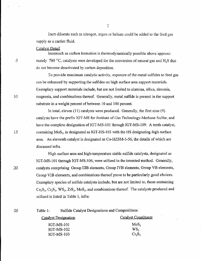
Inert diluents such as nitrogen, argon or helium could be added to the feed gas
supply as a carrier fluid.
Catalyst DetailInasmuch as carbon formation is thermodynamically possible above approxi-
mate y 700 “C, catalysts were developed for the conversion of natural gas and H$ that
do not become deactivated by carbon deposition.
To provide maximum catalytic activity, exposure of the metal sulfides to feed gas
can be enhanced by supporting the sulfides on high surface area support materials.
Exemplary support materials include, but are not limited to alumina, silica, zirconia,
magnesia, and combinations thereof. Generally, metal sulfide is present in the support
substrate in a weight percent of between 10 and 100 percent.
In total, eleven(11) catalysts were produced. Generally, the first nine (9)
catalysts have the prefix IGT-MS for institute of Gas Technology-Methane Sulfur, and
have the complete designation ofIGT-MS-101 through IGT-MS-109. A tenth catalyst,
containing MoS2, is designated as IGT-HS - 103 with the HS designating high surface
area. h eleventh catalyst is designated as CO-HZSM-5-56, the details of which are
discussed infra.
High surface area and high-temperature stable sulfide catalysts, designated as
IGT-MS-101 through IGT-MS-106, were utilized in the invented method. Generally,
catalysts comprising Group IIIB elements, Group IVB elements, Group VB elements,
Group VIB elements, and combinations thereof prove to be particularly good choices.
Exemplary species of sulfide catalysts include, but are not limited to, those containing
Ce&, Cr& WSZ, ZrS2, MoS2, and combinations thereof. The catalysts produced and
utilized is listed in Table 1, infra:
Table 1: Sulfide Catalyst Designations and Compositions.
Catalvst Decimation Catalvst Constituent
IGT-MS-101 MoS2
IGT-MS-102 WS2
IGT-MS-103 Cr2Sl

8
5
10
15
20
25
IGT-MS-104 Zrs,IGT-MS-105 Ce&IGT-h4S- 106 CosIGT-iMS- 107 Quartz GranulesIGT-MS-108 SilicaIGT-MS-109 FeS
Generally, the solid catalyst powders are made by sulfide conversion,
drying, reduction and calcination, wherein metal sulfides are precipitated from an
aqueous solution of the metal using ammonium hydro-sulfide. The catalysts are also
available commercially from Cerac Corporation of Milwaukee, Wisconsin.
The high surface area molybdenum sulfide catalyst IGT-HS-103 was a high
activity catalyst for hydrogenation. It is made by mixing a high surface area zirconia
powder with ammonium tetrathio-molybdate powder in a rolling mill. Approximately 20
to 50 grams of this powdered mixture is charged into a glass reactor with 100 ml/min of
hydrogen flowing through the bed of powder. The reactor is heated to 450 ‘C and
maintained for approximately 1 hour. Then, the mixture is slowly cooled to ambient
temperature.
Two non-sulfide catalysts IGT-MS-107 and IGT-MS-108 were also prepared.
These two catalysts were silicon dioxide catalysts. IGT-MS-107 was a low surface area
silicon dioxide that was crushed and sieved to -8 to +20 mesh. IGT-MS-108 was a high
surface area silicon dioxide prepared from silica gel. The powder was mixed with
deionized water to incipient wetness and dried at 100 ‘C overnight. The granules were
crushed and sieved to -8 to +20 mesh.
The resulting powders are pressed into wtiers via a pressure of between 500 psig
and 12,000 psig. Exemplary wafer sizes for laboratory-scale analysis are 2 mm by 15
mm ID, effected via a pressure application of 10,000 psig. The wafers were crushed and
sieved into -8 to +20 mesh granules before being placed in the catalyst reactors.
Methane/H2S Decom~osition DetailCatalysts for the hydrogen sulfide-methane reaction were tested by first placing

9
20 ml of granulated catalyst into a 22-mm 0.D. (outer diameter) quartz reactor. Nitrogen
was used as a diluent. Feed gas composition was 90 percent Nz, 1.1 to 3.33 percent H2S,
and 6.67 to 8.8 percent CH~. Flow rates ranged from 0.20 liters to 1.2 liters per minute.
The feed gases were controlled by mass flow controllers, depicted in FIG. 1 as elements
~ 19, exemplary controllers being the 5850C available through Brooks Instruments,
Hatfield, PA. Gas flow rates are calibrated by a dry test meter, 20 such as those available
from American Meter Company, Horsham, PA.
During a typical run, the temperature varied from 700 “C to approximately 1,100
‘C. Also, the ratio of HZS to CHQwas varied from 2 to 8. Highest yields (95 percent) of
10 conversion occurred at a CHq/H2S ratio of 4. Lastly, the residence time varied from 1 to 5
seconds.
Product gas compositions are determined via any suitable sampling devices 22. In
an exemplary arrangement, gas samples were analyzed by gas chromatography with a
thermal conductivity detector and a flame photometric sulfur detector.
15 Generally, the yield of CS2 increases with temperatures up to 1,100 “C. As
illustrated in FIGS. 2 and 3, high yields were achieved by catalysts comprising transition
metal sulfide powders, such as catalyst IGT-MS - 103 (which is a chromium sulfide
(Cr2S~) catalyst), and IGT-MS-105 (which is a cerium sulfide (CeS) catalyst that goes
through a bulk phase change to Ce2S~). FIG. 2 depicts yield and conversion data
20 obtained when IGT-MS- 103 catalyst is used. FIG. 3 depicts yield and conversion data
obtained when IGT-MS-105 catalyst is used. In both instances, residence times were 1
second, and the H2S/CHq feed ratio was held to 4.
At 1100 ‘C, the highest yields were achieved by catalysts IGT-MS-103 and IGT-
MS-1 05. The order of conversion among all the methane sulfir conversion catalysts was
25 IGT-MS-103, IGT-MS-105 > IGT-MS-108 > IGT-MS-107 > IGT-MS-104 > IGT-MS-
102> empty reactor> IGT-MS-101 >IGT-MS-106>IGT-MS-109.
These transition metal sulfide powder catalysts compared favorably to other
catalyst types when reactor residence time was held at 1 second for a H&/CHq feed ratio
of 4 (FIG 4), a feed ratio of 8 (FIG. 5), and a feed ratio of 2 (FIG. 6). As a control,

10
10
15
20
25
conversion rates were also recorded when the reactor vessel was without a catalyst.
designated as “empty.”
Good yields were obtained even when feed gas composition was adjusted to
simulate industrial conditions. For example, when COZ was added to the mix, and
particularly at an H2S/COz ratio of 8, yields above 50 percent were realized.
For catalysts IGT-MS- 103 and IGT-MS- 105, CSZ yield is based on the moles of
CSZ produced divided by the moles of methane fed. CSZ yield increases sharply above
900 “C to a maximum of near 100 percent at 1,100 “C.
The chromium catalyst (IGT-MS-1 03) composition ranged iiom 30 to 50 mole
percent chromium and 50 to 70 mole percent sulfur.
The ceriurn catalyst (IGT-MS- 105) composition ranged from 30 to 60 mole
percent cerium and 40 to 70 mole percent sulfir.
ExamvleA cerium sulfide powdered catalyst was pelleted and 40 grams of it was loaded
into a 22 mm quartz reactor. The feed gas flow was 1.14 standard liters per minute. The
composition of the feed was 90 percent nitrogen, 8 percent hydrogen sulfide and two
percent methane. The reactor was operated at 1 atmosphere pressure and at 1,000 “C.
Product gas compositions were determined as follows:
HZS 4.8 %Nz 87.9 %H2 5.4 !40
CS* 1.6%
CHO 0.4 %
The rate of production of CSZ was 1.2 mini-moles CSZ /g.cat. hr. The rate of
production of Hz was 4.2 mini-moles H2/g. cat. hr.
Gasoline Monomer Catalvst DetailIn addition to the series of catalysts developed for HC- and sulfide- conversion,
another catalyst composition (actually a mixture of the MoSZ catalyst described supra, i.e.,
IGT-HS-1 03, and the zeolite catalyst) and then the zeolite catalyst separately, was used to

11
10
15
20
25
generate gasoline monomers from the product of the first conversion.
The zeolite catalyst, CO-HZSM-5-56, was made by ion exchanging cobalt into an
HZSM-5 zeolite obtained from PQ Corporation, Valley Forge, PA. Ion exchange of the
zeolite was performed by making a solution of cobalt nitrate with sufficient moles of
cobalt to exchange with 56 percent of the H sites (acid sites) on the zeolite. The zeolite
powder was slurried into the cobalt solution and the slurry was heated to 70 ‘C for 18
hours. The zeolite powder was filtered and dried.
The resulting powder was pressed into wafers and crushed and sieved similar to
catalyst fabrication described supra. The catalyst was sized to -8 to +20 mesh, and 20 ml
was loaded into a second reactor, downstream from the quartz reactor.
The conversion of methane to gasoline-range hydrocarbons was conducted in a
single unit containing two reactors. The first reactor, illustrated in FIG. 1 and discussed
above, was devoted to the conversion of methane to carbon disulfide. The second reactor
was used to convert carbon disulfide to liquid hydrocarbons, the reaction for which is
depicted in Equation 2, supra. This unit could be identical to the first reactor. However,
stainless steel exhibits adequate thermal and chemical resistivity for the second conver-
sion. For bench-top analysis, a 3/4 inch, Schedule 80 stainless-steel pipe was sufficient.
Pressures of this hydrogenation reaction can vary from atmospheric to more than
400 psig. The operating pressure of this reaction can be adjusted to match the exit of the
first reactor, thereby negating the necessity of a booster compressor.
When solely zeolite catalyst is used, CSZ was converted at rates ranging from
between 23 percent and 55 percent, as can be determined in Table 1, infra:
Table 1: CS2 HYDROGENATION OVER CO-H-ZSM-5-56 AT AMBIENTPRESSURE AND Hz/CS2 RATIO=5.1
Space Temp 0/0Conversion O/OConversion O/OSelectivityVelocity, h-’ “c H, Cs, C4+
478 407 13 25 NA431 16 33 25

.
5
10
15
20
25
30
35
415
343
405 22 23430 29 36450 32 42
470 37 51
405 39 23430 39 36450 45 45470 47 55
52342517
49302617
The results in Table 1 show that both CSZ hydrogenation and C~+hydrocarbon
selectivity have strong temperature dependencies. CSZ conversion increases substantially as
temperature is raised from 405 “C to 470 ‘C. In contrast, CQ+selectivity decreases with
increasing temperature.
CSZ hydrogenation was also carried out using a mixture of MoSZ (IGT-HS-103) and
CO-HZSM-5-56 catalyst. As can be determined in Table 2, below, the use of the MoS2
hydrogenation catalyst in conjunction with the HZSM-5 zeolite catalyst resulted in near
complete conversion of the carbon disulfide. This indicates that the addition of a sulfur-
tolerant hydrogenation catalyst has a synergistic effect in promoting the conversion of CSZ to
hydrocarbons. Generally, the hydrogenation agent is present in a weight percent to the zeolite
in a range of 20 to 80.
Table 2: CS2 HYDROGENATION OVER A MIXTURE OF MoSZ AND Co-H-ZSM-5-56 AT AMBIENT PRESSURE AND H2/CSz RATIO=5. 1
Space Temp 0/0Conversion ‘/oConversion O/OSelectivityVelocity, h-] “c H, cs~ C4+
343 434 38 100 11350 36 98 45
325 27 95 51

.
10
15
Up to 1 percent of the raw product gas resulting from this catalyst mixture was
methyl mercaptan. In this case, the MoSZ may be hydrogenating the CSZ to methyl
mercaptan, which in turn is converted to hydrocarbons over ZSM-5 catalysts.
Conversion rates are affected by varying reaction parameters. For example,
suitable space velocities can range from 300 to 30,000 vol gas/vol catalyst per hour.
Space velocity is the velocity of the feed gas divided by the volume of the catalyst
utilized and is generally designated as follows:
[ 1/”Space Velocity = ml/hr ml
wherein mI/hr is the feed gas volumetric rate and the ml denominator is the volume of the
catalyst.
Alternatively, conversion rates can also be effected with reactor residence times
from between 0.1 to 10 seconds. Temperatures of the catalyst can range from 200 to 500
“c.
While the invention has been described with reference to details of the illustrated
embodiment, these details are not intended to limit the scope of the invention as defined
in the appended claims.

.
ABSTRACT
A method for converting hydrocarbons and hydrogen sulfide to carbon disulfide
and hydrogen is provided comprising contacting the hydrocarbons and hydrogen sulfide
to a hi-functional catalyst residing in a controlled atmosphere for a time and at a tempera-
ture sufficient to produce carbon disulfide and hydrogen. Also provided is a catalyst for
converting carbon sulfides and hydrogen sulfides to gasoline range hydrocarbons
comprising a mixture containing a zeolite catalyst and a hydrogenating catalyst.

19 1<
Mix~--13
CHa
14+
HIS
--1
t
\Pressure Gauge
Thermocouple
Vent
.
m
i2
“
FIG 1
Scrubber

%
%
100
90
80
70
60
50
40
30
20
10
0
I I /7
/ A
1 f
I I4 I
i/i
I
T T I I i
600 700 800 900 1000 1100 1200
Temperature, C
FIG2
E+CS2 ‘field
+ Hz yield
+--CH4 Conv.
-0-H2S Conv.
100
90
80
70
60
50
40
30
20
10
0
I I I I I I
T 1
600 700 800 900 1000 1100 1200
Temperature, C
E+CS2 yield
+ HZ yield
-+-- CH4 Conv.
-+- H2S Conv.
FIG 3

.
1
100908070
%-&
403020’10
0 -f r-
600 700 800 900 1000 7100 ‘lZoo
Temperature, C
FIG4
600 700 800 900 1000 1100 120(1
Temperature, C
FIG5
~ MS-101
——E+—MS-102
~ MS--lO3
~ MS-104
~ MS-’IO5------ MS-106
~ MS-107
— MS-108
— MS-109
~ MS-101
~ MS-102
~ MS-103
~ MS-104
~ MS-105.--..- MS-106
~ MS-107
— MS-108
— MS-109
–—Empty
●