metrology lab manual
DESCRIPTION
For 2013 regTRANSCRIPT
1
A Handbook of ME 6513- METROLOGY AND MEASUREMENTS LAB
TAGORE INSTITUTE OF ENGINEERING AND TECHNOLOGY
DEVIYAKURICHI – 636112
DEPARTMENT OF MECHANICAL ENGINEERING
LAB MANUAL
ME 6411 MANUFACTURING TECHNOLOGY LAB - II
II - Year / IV - Semester
NAME : …………………………………………..
REG.NO : …………………………………………..
Subject In-charge
Mr.K.RAMAMOORTHY., M.E., MBA.

2

INDEX
S.NO NAME OF THE EQUIPMENTPAGE
NO
1. Vernier Height Gauge
2. Bore diameter measurement
3. Mechanical comparator
4. Measurement of Gear Parameters Using Gear tooth Vernier caliper
5. Taper Angle Measurement Using Sine Bar
6. Measurement of Dimension of Given Specimen Using Tool Maker’s Microscope
7. Measurement of Straightness And Flatness Using Auto Collimator
8. Floating Carriage Micrometer
9. Torque Measuring Setup
10. Force measurement using Load cell
11. Temperature measurement
12. Surface finish measuring equipment
13. Co ordinate measuring machine
14. Bore diameter measurement using telescope gauge
3
EX.NO:
DATE: INTRODUCTION TO METROLGY
Aim:To study about the basics of the engineering metrology and measurements.
FUNDAMENTALS
METROLOGYMetrology is a “Science of measurement” . The most important parameter in metrology is the
length. Metrology is divided into Industrial Metrology and Medical Metrology under consideration of its application and may be divided into metrology of length and Metrology of time under consideration of its quantity. Metrology is mainly concerned with the following aspects:
Unit of measurement and their standards.Errors of measurement.Changing the units in the form of standards.Ensuring the uniformity of measurements.New methods of measurement developing.Analyzing this new methods and their accuracy.Establishing uncertainty of measurement.Gauges designing, manufacturing and testing.Researching the causes of measuring errors.Industrial Inspection.
FUNCTIONS OF METROLOGYTo ensure conservation of national standards.Guarantee their accuracy by comparison with international standards.To organise training in this field.Take part in the work of other National Organization.To impart proper accuracy to the secondary standards.Carry out Scientific and Technical work in the field of measurement.Regulate, supervise and control the manufacturer.Giving advice to repair of measuring instruments.To inspect and to detect guilty of measurement.
APPLICATIONS OF METROLOGYIndustrial MeasurementCommercial transactionsPublic health and human safety ensuring.
NEED OF INSPECTIONTo determine the fitness of new made materials, products or component part and to compare the materials, products to the established standard. It is summarized as:
To conforming the materials or products to the standard.To avoid faulty product coming out.To maintain the good relationship between customer and manufacturer.To meet the interchangeability of manufacturer.To maintain the good quality.
4

To take decision on the defective parts.To purchase good quality raw materials.To reduce the scrap.
BASIC CONCEPTS OF MEASUREMENTSMeasurement is the outcome of an opinion formed by observers about some physical quantity.Measurement is an essential part of the development of technology.Measurement is a complex of operations carried out by means of measuring instruments.
ELEMENTS OF A MEASUREMENTMeasurand: It is a physical quantity or property (length, diameter, thickness, angle etc.).Reference: Reference is a physical quantity or property and comparisons are made by them.Comparator: Comparing measurand with some other reference.
NEED FOR MEASUREMENTTo determine the true dimensions of a part.To increase our knowledge and understanding of the world.Needed for ensuring public health and human safety.To convert physical parameters into meaningful numbers.To test if the elements that constitute the system function as per the design.For evaluating the performance of a system.For studying some basic laws of nature.To ensure interchangeability with a view to promoting mass production.To evaluate the response of the system to a particular point.Check the limitations of theory in actual situation.To establish the validity of design and for finding new data and new designs.
METHODS OF MEASUREMENT1. Direct comparison with Primary or Secondary Standard.2. Indirect comparison with a standard through calibration system.3. Comparative method.4. Coincidence method.5. Fundamental method.6. Contact method.7. Transposition method.8. Complementary method.9. Deflection method.
1) Direct method:The value to be measured is directly obtained. Examples: Vernier calipers, Scales.
2) Indirect method:The value of quantity to be measured is obtained by measuring other quantities. Diameter measurement by using three wires.
3) Comparative method:In this method, the quantity to be measured is compared with other known value.Example: Comparators.
4) Coincidence method:The value of the quantity to be measured and determined is coincide with certain lines
5
and signals.
5) Fundamental method:Measuring a quantity directly in related with the definition of that quantity.
6) Contact method:The sensor or measuring tip of the instrument touches the area (or) diameter (or) surface to be measured.
Example: Vernier caliper.
7) Transposition method:In this method, the quantity to be measured is first balanced by a known value and then it is balanced by other new known value. Example: Determination of mass by balancing methods.
8) Complementary method:The value of quantity to be measured is combined with known value of the same quantity.
Example: Volume determination by liquid displacement.
9) Deflection method:The value to be measured is directly indicated by a deflection of pointer. Example: Pressure measurement.
RESULT:Thus the basics of the engineering metrology and measurements were studied.
6
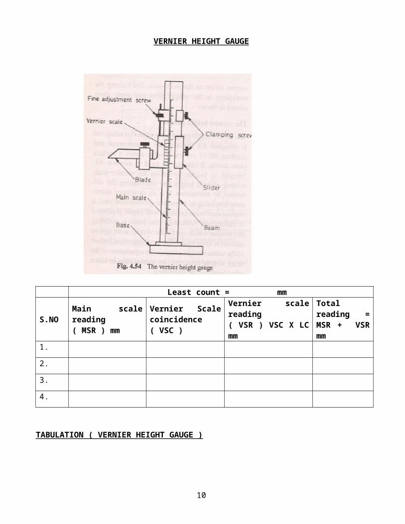
VERNIER HEIGHT GAUGE
Least count = mm
S.NOMain scale reading( MSR ) mm
Vernier Scale coincidence( VSC )
Vernier scale reading( VSR ) VSC X LC mm
Total reading = MSR + VSR mm
1.
2.
3.
4.
TABULATION ( VERNIER HEIGHT GAUGE )
7
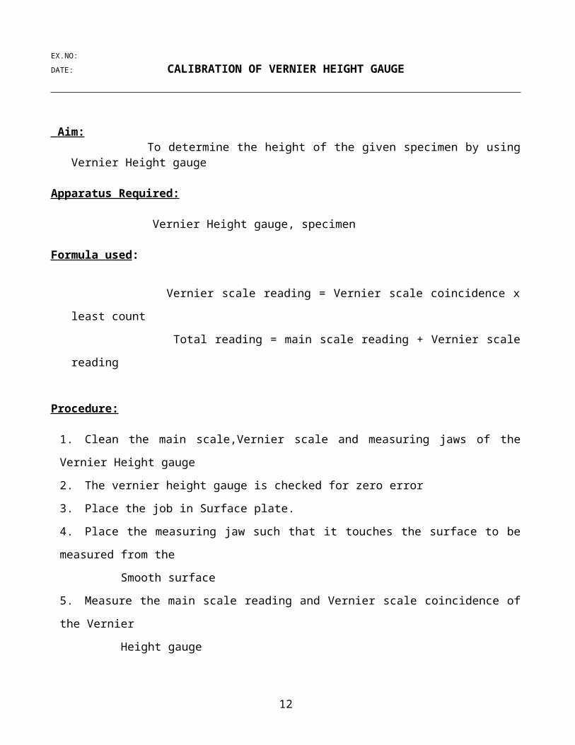
EX.NO:
DATE: CALIBRATION OF VERNIER HEIGHT GAUGE
Aim:
To determine the height of the given specimen by using Vernier Height gauge
Apparatus Required:
Vernier Height gauge, specimen
Formula used:
Vernier scale reading = Vernier scale coincidence x least count
Total reading = main scale reading + Vernier scale reading
Procedure:
1. Clean the main scale,Vernier scale and measuring jaws of the Vernier Height gauge
2. The vernier height gauge is checked for zero error
3. Place the job in Surface plate.
4. Place the measuring jaw such that it touches the surface to be measured from the
Smooth surface
5. Measure the main scale reading and Vernier scale coincidence of the Vernier
Height gauge
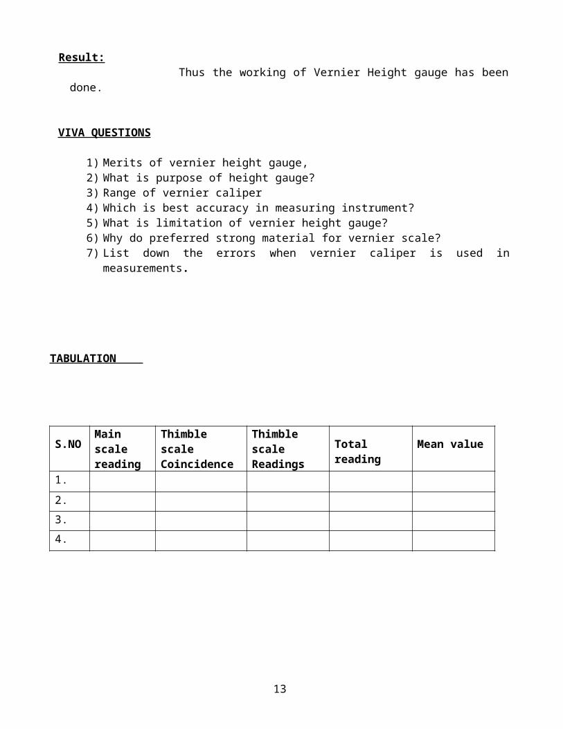
Result: Thus the working of Vernier Height gauge has been done.
VIVA QUESTIONS
1) Merits of vernier height gauge,2) What is purpose of height gauge?3) Range of vernier caliper4) Which is best accuracy in measuring instrument?5) What is limitation of vernier height gauge?6) Why do preferred strong material for vernier scale?7) List down the errors when vernier caliper is used in measurements.
8
TABULATION
S.NO Main scale reading
Thimble scaleCoincidence
Thimble scaleReadings
Total reading Mean value
1.
2.
3.
4.
9
EX.NO:
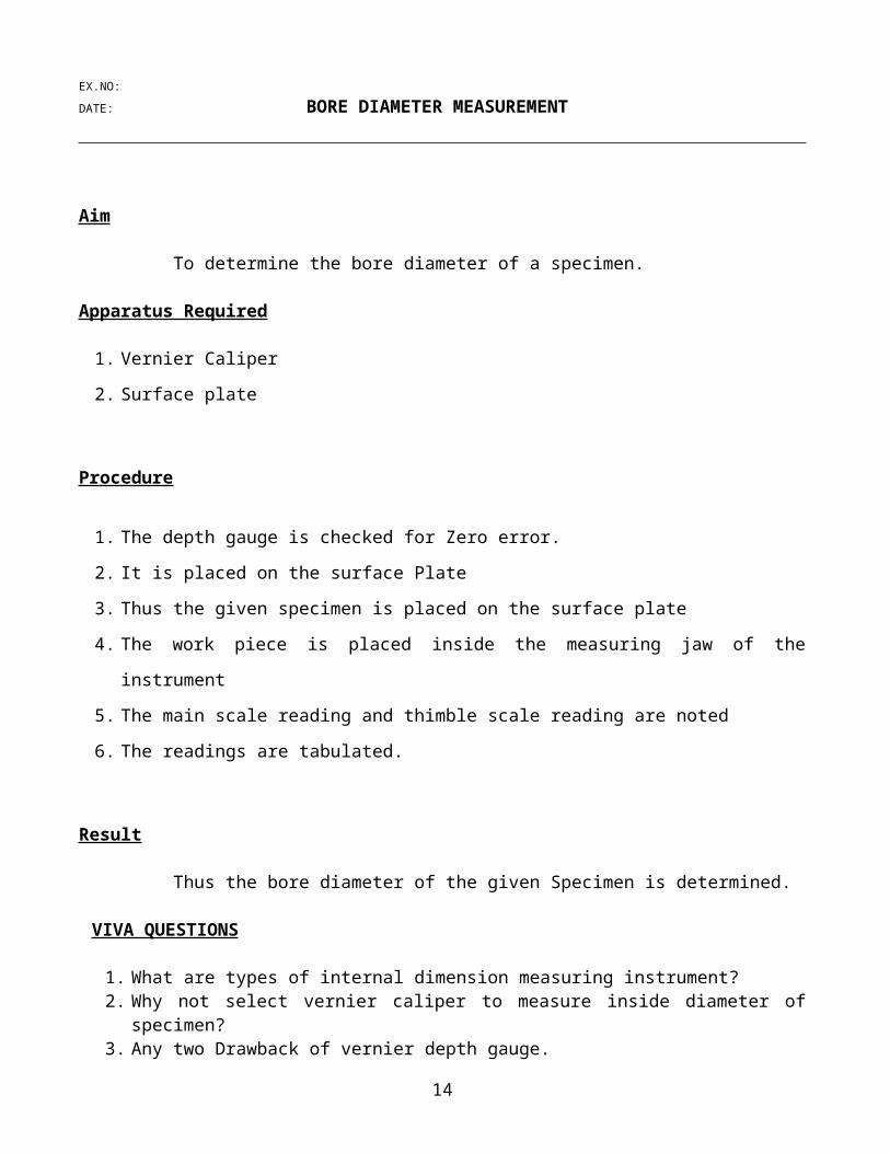
DATE: BORE DIAMETER MEASUREMENT
Aim To determine the bore diameter of a specimen.
Apparatus Required
1. Vernier Caliper
2. Surface plate
Procedure
1. The depth gauge is checked for Zero error.
2. It is placed on the surface Plate
3. Thus the given specimen is placed on the surface plate
4. The work piece is placed inside the measuring jaw of the instrument
5. The main scale reading and thimble scale reading are noted
6. The readings are tabulated.
Result
Thus the bore diameter of the given Specimen is determined.
VIVA QUESTIONS
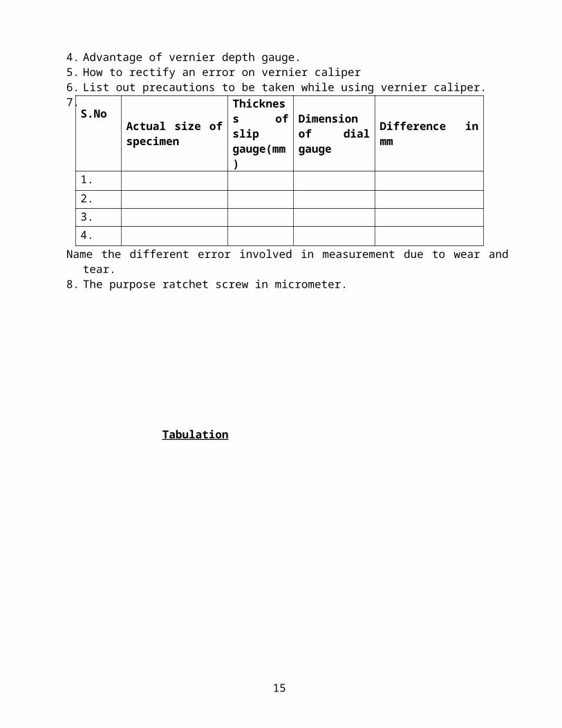
1. What are types of internal dimension measuring instrument?2. Why not select vernier caliper to measure inside diameter of specimen?3. Any two Drawback of vernier depth gauge.4. Advantage of vernier depth gauge.5. How to rectify an error on vernier caliper6. List out precautions to be taken while using vernier caliper.7. Name the different error involved in measurement due to wear and tear. 8. The purpose ratchet screw in micrometer.
10

Tabul ation S.No Actual size of
specimen
Thickness of slip gauge(mm)
Dimension of dial gauge
Difference in mm
1.
2.
3.
4.
11
EX.NO:
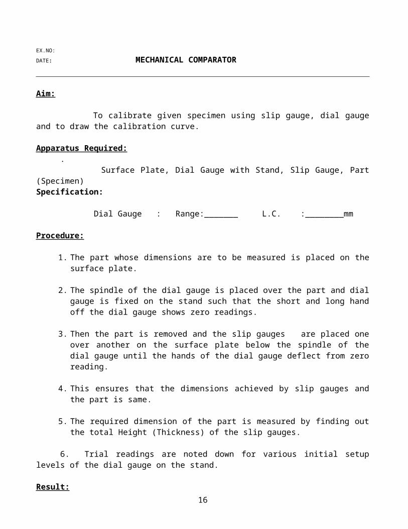
DATE: MECHANICAL COMPARATOR
Aim: To calibrate given specimen using slip gauge, dial gauge and to draw the calibration curve.
Apparatus Required: . Surface Plate, Dial Gauge with Stand, Slip Gauge, Part (Specimen) Specification:
Dial Gauge : Range:_______ L.C. :________mm
Procedure:
1. The part whose dimensions are to be measured is placed on the surface plate.
2. The spindle of the dial gauge is placed over the part and dial gauge is fixed on the stand such that the short and long hand off the dial gauge shows zero readings.
3. Then the part is removed and the slip gauges are placed one over another on the surface plate below the spindle of the dial gauge until the hands of the dial gauge deflect from zero reading.
4. This ensures that the dimensions achieved by slip gauges and the part is same.
5. The required dimension of the part is measured by finding out the total Height (Thickness) of the slip gauges.
6. Trial readings are noted down for various initial setup levels of the dial gauge on the stand.
Result:
The various dimensions of the given Part measured are:
A : __________mmB : __________mmC : __________mm
VIVA QUESTIONS
1. What are slip gauges?2. List out the slip gauge accessories.3. List out the requirement of slip gauges.4. How much of slip gauges with steps in a slip gauge set?5. What is wringing of gauge blocks?6. What are steps followed to measure a height using slip gauge?
12
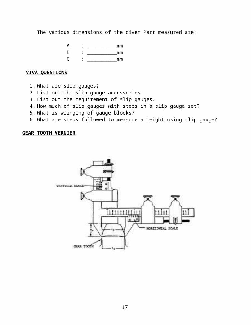
GEAR TOOTH VERNIER
13
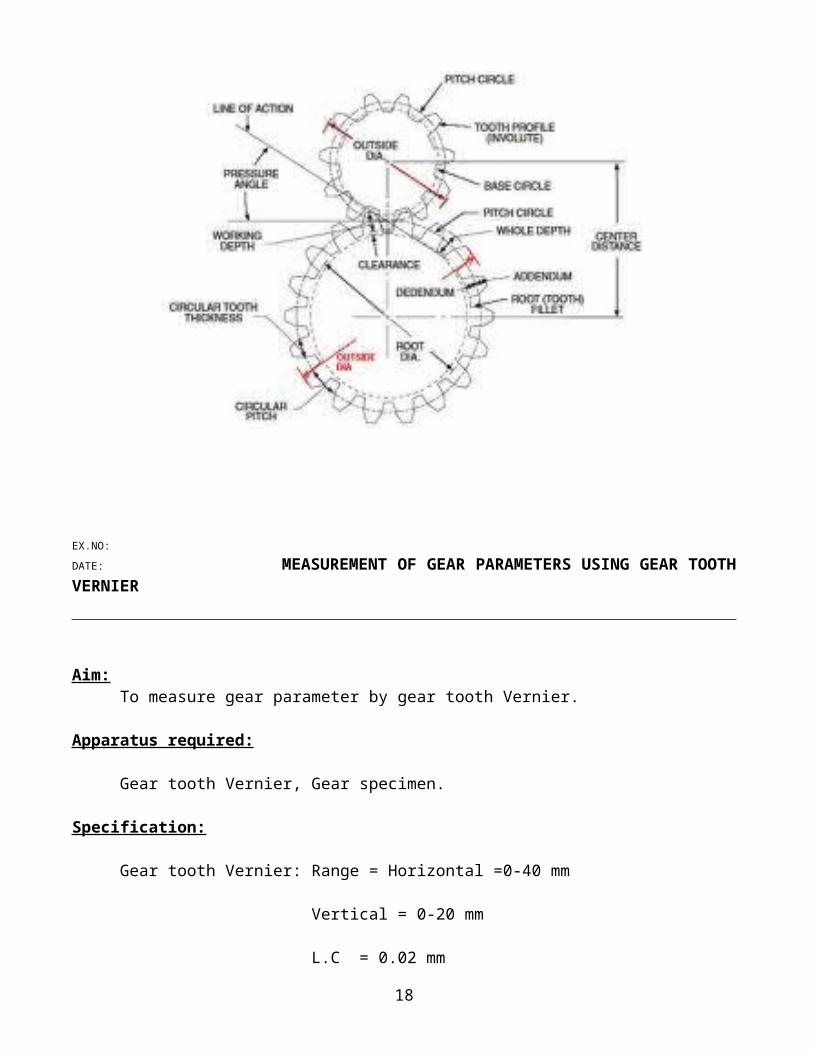
EX.NO:
DATE: MEASUREMENT OF GEAR PARAMETERS USING GEAR TOOTH VERNIER
Aim:To measure gear parameter by gear tooth Vernier.
Apparatus required:
Gear tooth Vernier, Gear specimen.
Specification:
Gear tooth Vernier: Range = Horizontal =0-40 mm
Vertical = 0-20 mm
L.C = 0.02 mmFormula:
1. W = NM sin (90/N)
2. d = NM--------- 2
3. m = D ------------- (N+2)
Where W = Chordal width of tooth in mm
d= Chordal addendum of gear in mm
M = Module of gear in mm
N = No. of teeth
D = out side Dia in gear in mm
Procedure:1. The N, D of the given gear block are measured.
2. The module m’ it then calculated.
3. Theoretical values of ‘W’ and’d’ are computed.
14
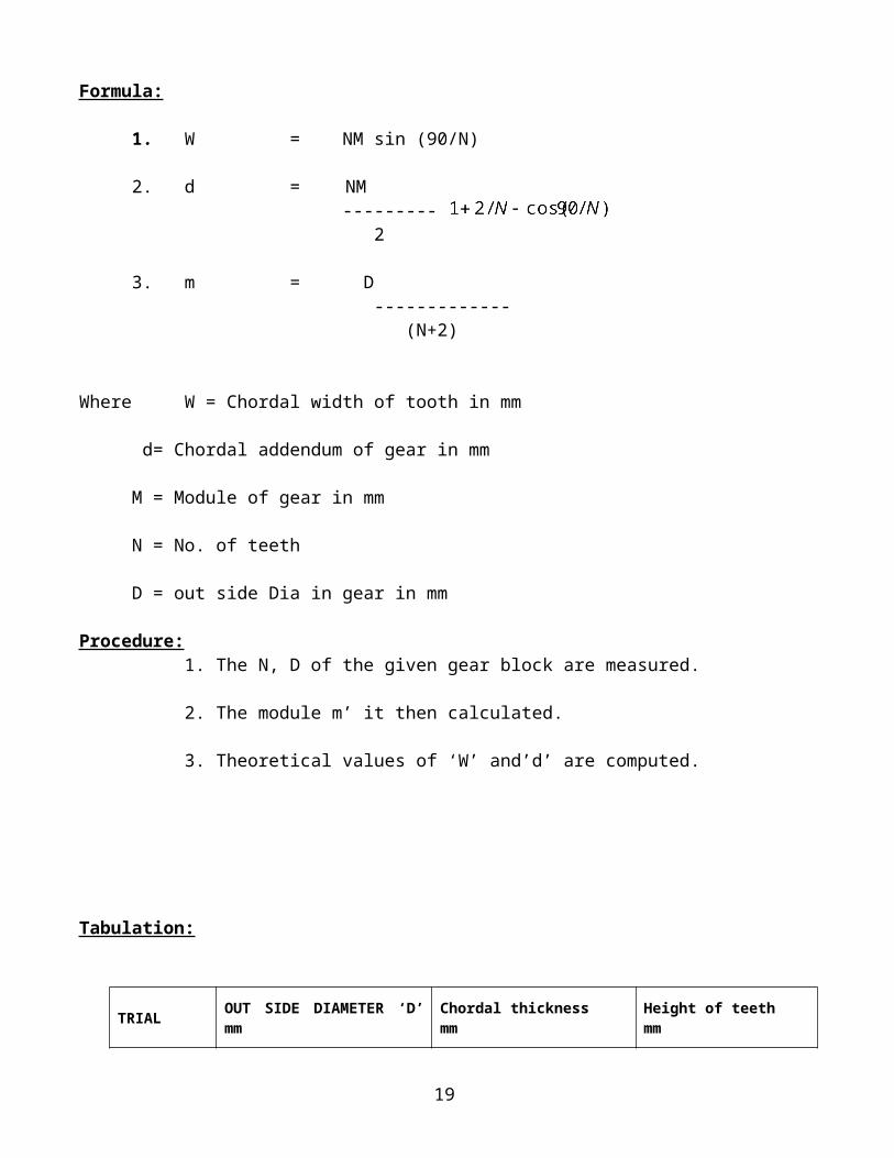
Tabulation:
TRIALOUT SIDE DIAMETER ‘D’ mm
Chordal thicknessmm
Height of teethmm
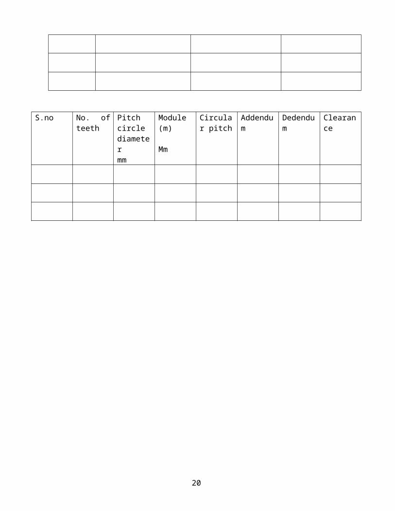
S.no No. of teeth
Pitch circle diametermm
Module (m)
Mm
Circular pitch
Addendum Dedendum Clearance
15
4. Theoretical values of ‘W’ is set in horizontal Vernier scale of gear tooth Vernier and corresponding actual ‘d’ value scale.
5. Theoretical values of ‘c’ is set and ‘W’ is measured along Horizontal scale.
6. This procedure is repeated for 5 teeth and value tabulated.
Result:
Thus the chordal thickness and addendum of gear is measured using gear tooth Vernier.
The actual values are W = D =
VIVA QUESTIONS
1. What are methods available for measuring tooth thickness?2. What is chordal thickness?3. What is module?4. Why want calculate module of teeth?5. Define pitch circle.6. What are methods used to measure the tooth thickness?
16
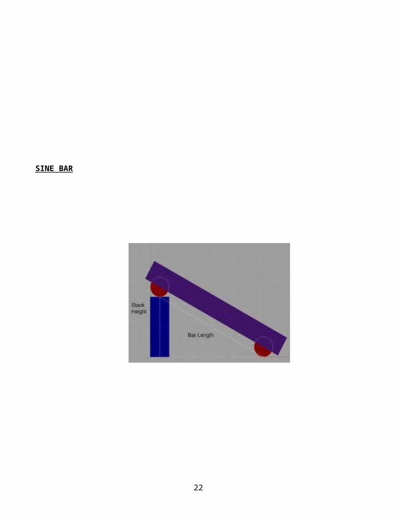
SINE BAR
17
EX.NO:
DATE: TAPER ANGLE MEASUREMENT USING SINE BAR AND SLIP GAUGE
Aim:
To measure the taper angle of the given specimen using sine bar
Apparatus Required:
Surface plate, Dial gauge with stand, Sine bar, Slip gauge, Bevel protractor & specimen.
Specification:
Sine bar : Range:
Formula:
Taper angle ‘θ’ = Sin-1 (h/l) in degrees
Where, h = the total height (thickness) of the slip gauges in mm
l = the standard length of the sine bar in mm
Procedure:
1. The taper angle of the specimen is first found out approximately with the help of a bevel
protractor.
2. The sine bar is set at this angle on the surface plate with the help of the slip gauges as shown in
the figure.
3. The specimen is placed on the sine bar so that its top taper surface is parallel to the surface
plate.
4. The parallelism is checked and adjusted by increasing or decreasing the height level of the slip
gauges, so that there should be no deflection in the long hand of the digital gauge when the
spindle of the dial gauge is moved over the specimen surface.
5. The total height (thickness) of the slip gauges is noted down.
6. Trial readings are taken by placing the specimen at different points of the sine bar surface.
18
For Small Specimen:
Trial Length of sine BarTotal height of the slip gauge Reading (mm)
Taper angle(θ)
Model Calculation:
19
Result:
The taper angle of the given specimen isa. Using bevel protractor =_________________________ degreesb. Using sine bar =_________________________ degrees
VIVA QUESTIONS
1) How do find the taper angle?2) Limitation of sine bar.3) How to specify the sine bar?4) Why do you select std length of sine bar?5) What is purpose of hole provided in sine bar?6) How can u measure angle for heavier component?7) Which is best accuracy method to find angle?8) What is formula for angle measurement?
20
21
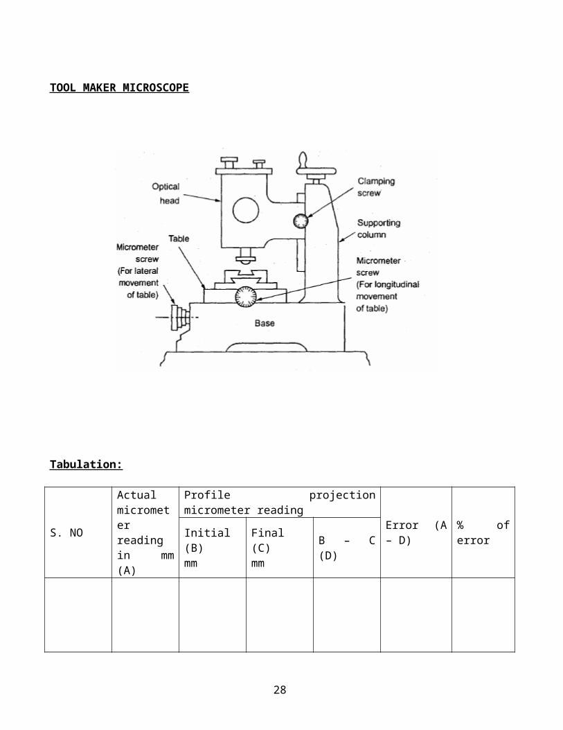
TOOL MAKER MICROSCOPE
Tabulation:
S. NO
Actual micrometer reading in mm (A)
Profile projection micrometer readingError (A – D) % of error
Initial (B)mm
Final (C)mm
B – C (D)
To find the flank angle:
S.NoInitial angle in degree (A)
Final angle in degree (B)
Difference between A & B
22

EX.NO:
DATE: MEASUREMENT OF DIMENTION OF GIVEN SPECIMEN USING TOOL MAKER’S MICROSCOPE
Aim: To measure various dimension of a given specimen using Tool maker’s microscope. Apparatus Required:
Tool maker’s microscope, Specimen, Eyepiece.
Procedure:
1. To find the Major and Minor diameter: One end of screw thread in made to coincide with cross wire & fixed. Reading is taken. The different between readings given linear measurement. 2. Measurement of pitch:
The contour is get so that the same it an screen. The reading of micrometer is noted. The reading of are subtracted & different is noted.
3. Measurement of thread angle:
The screw is rotated till linear cross wire coincides with flank of thread profile. The angle of screw rotation and than the same line coincides with flank thread.
23
24
Result:
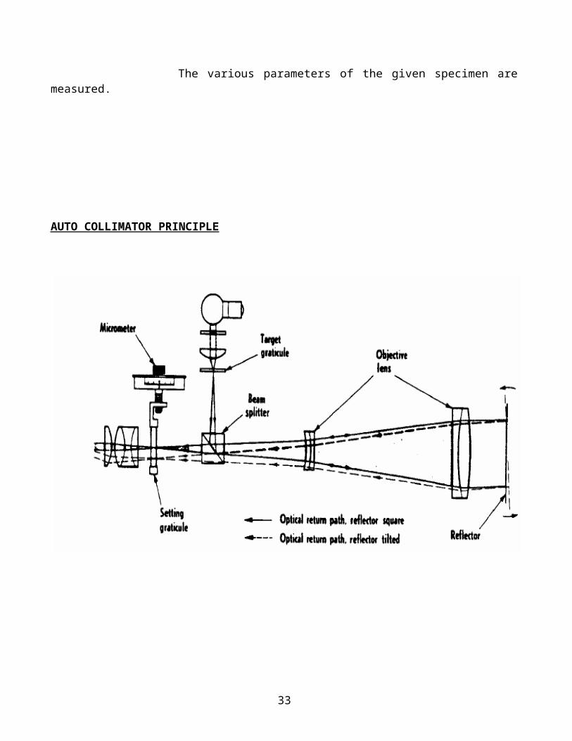
The various parameters of the given specimen are measured.
25

AUTO COLLIMATOR PRINCIPLE
26
EX.NO:
DATE: MEASUREMENT OF STRAIGHTNESS AND FLATNESS USING AUTO COLLIMATOR
Aim:To test the flatness of the given specimen surface using auto collimator.
Apparatus required:
Collimator unit, Base, plain reflector, optical Scanner
Procedure:
1. Switch on the light and observe the measuring gratitude through eyepiece.
2. The smallest division of liner scale is 1 minute.
3. Bring the plain reflector in front of autocollimator to get a reflected.
4. Depending upon variation in surface position of target will change on measuring scale.
5. There upon the position of intersection point of cross bar line will measuring gratitude is the
deviation in minute.
6. Using micrometer provided for eyepiece we can measure the function upto 10 seconds.
27
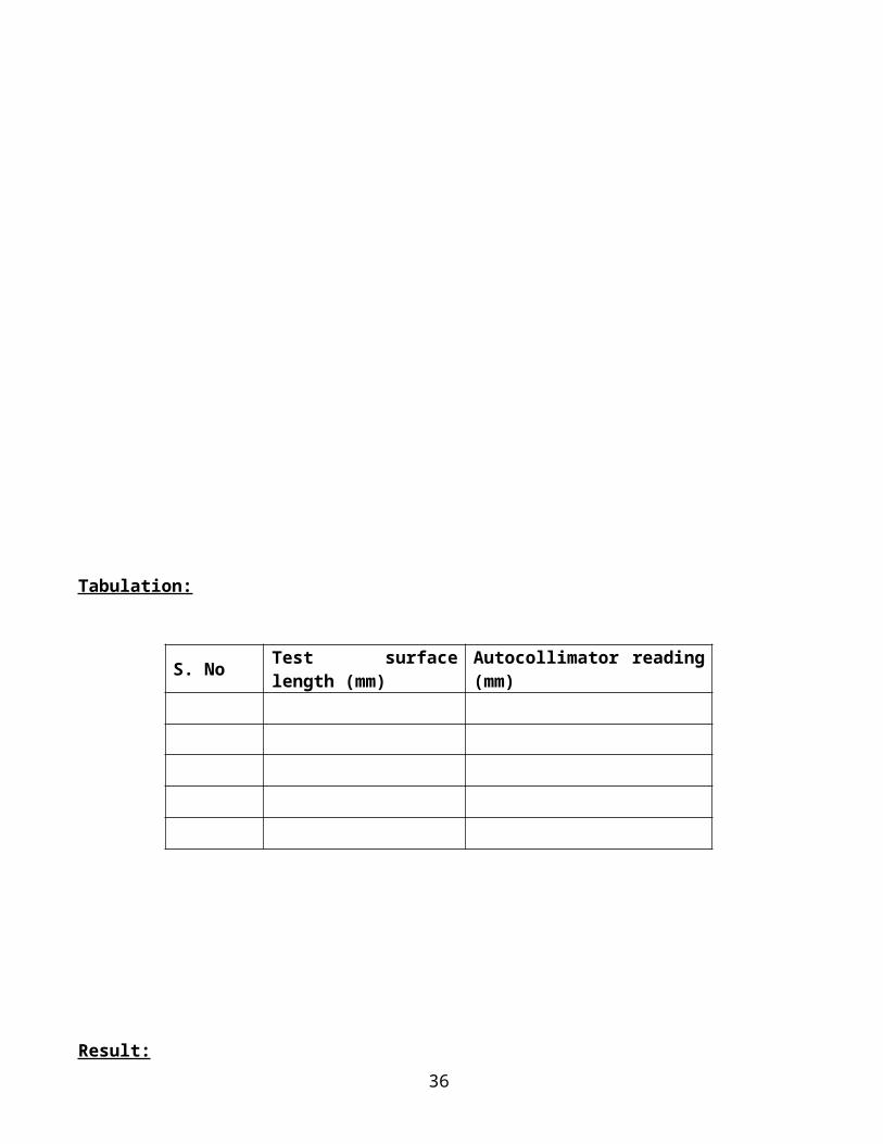
Tabulation:
S. No Test surface length (mm) Autocollimator reading (mm)
Result:
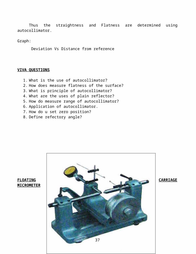
Thus the straightness and Flatness are determined using autocollimator.
Graph:
Deviation Vs Distance from reference
VIVA QUESTIONS
1. What is the use of autocollimator?2. How does measure flatness of the surface?3. What is principle of autocollimator?4. What are the uses of plain reflector?5. How do measure range of autocollimator?6. Application of autocollimator.7. How do u set zero position?8. Define refectory angle?
28
FLOATING CARRIAGE MICROMETER
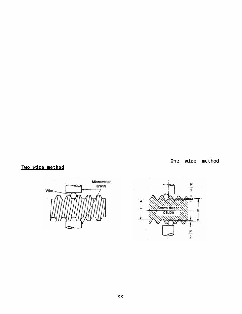
One wire method Two wire method
29

30

EX.NO:
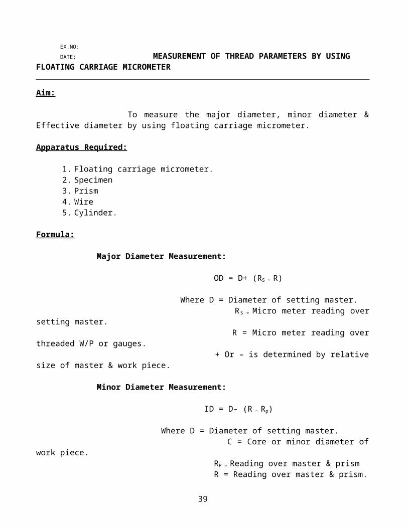
DATE: MEASUREMENT OF THREAD PARAMETERS BY USINGFLOATING CARRIAGE MICROMETER
Aim: To measure the major diameter, minor diameter & Effective diameter by using floating carriage micrometer.
Apparatus Required:
1. Floating carriage micrometer.2. Specimen3. Prism4. Wire5. Cylinder.
Formula:
Major Diameter Measurement:
OD = D+ (RS ~ R)
Where D = Diameter of setting master. RS = Micro meter reading over setting master. R = Micro meter reading over threaded W/P or gauges. + Or – is determined by relative size of master & work piece.
Minor Diameter Measurement:
ID = D- (R ~ Rp)
Where D = Diameter of setting master. C = Core or minor diameter of work piece. RP = Reading over master & prism R = Reading over master & prism.
Measurement of effective diameter by using 2 wire method:
E = T+P
T= D+ (RW ~ ROW) RW = Reading measured over setting master with wire
ROW = Reading measured over work piece over wire
P = (0.86603 * p) – WW =Mean diameter of cylinder wire used = p = Pitch of thread =
31

TABULATION (STD SPECIMEN)
S.NoDiameter of setting master (mm)
Reading over setting master and prism(R)
Reading over work piece and prism( RO mm)
Minor diameter(mm)
Major Diameter Measurement
Effective Diameter Measure By Two Wire Method
S.No
Diameter of setting master (mm)
Reading over setting master with wire(R)
Reading over work piece( RO mm)
Difference(R ~ RO)
Measured dimension of the cylinder(mm)
Effective diameter(mm)
32
Where E = Effective or pitch diameter.
T = Measured dimension using cylinder. RW= Reading measured over setting master with wire. ROW= Reading measured over work piece over wire.
P = (0.86603 * p) – W W =Mean diameter of cylinder wire used = 1.35 mm
p = Pitch of thread = 2 mm
Procedure:1. The setting master is held b/w center and taken the reading at the diameter say RS
2. The master cylinder is then replaced by a threaded work piece and R is taken.
3. Take the reading on micrometer and indicator in such a way that radius portion of
prism touches master.
4. The cylinder or wire should be chosen so that when placed b/w the threads, they
should contact about halfway down the flanks.
Result:
Thus, the thread parameters of a screw thread are measured using floating carriage micrometer.
VIVA QUESTION
1) Name the various methods for measuring effective diameter.2) What is best size of wire?3) What are the direct angular measurements methods?4) What is mean by effective diameter?5) Define three wire methods.6) Define pitch radius.7) define root8) Why need standard block?
33

TORQUE MEASUREMENT
34
EX.NO:
DATE: TORQUE MEASUREMENT
Aim:
To measure the torque using shear type load cell.
Apparatus Required:
1. Torque measurement equipment
2. Stand
3. lever
4. stain gauge
5. Weight.
Formula Used:
Calculated Torque = Load x Distance (kg-m)
Description:
Torque is the tangential force to set a body in rotation. It is represented as a vector of a force
for a rigged body undergoing force rotation about a single axis.
Torque = DX,
D = Moment of inertia of body about the axis.
X = Angular acceleration.
Thus torque is the essential tensional twisting about its axis of rotation. In this setup shear
type load is used to measure the torque a inverse method of measuring the load with the output immune
to side load and bending moment is based on measurement of shear components. The load cell is
balancing a beam supported on both ends.
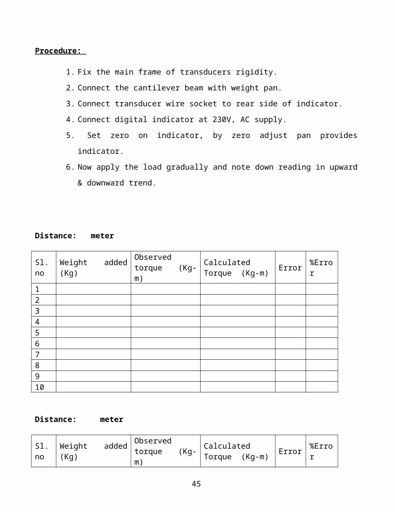
Procedure:
1. Fix the main frame of transducers rigidity.
2. Connect the cantilever beam with weight pan.
3. Connect transducer wire socket to rear side of indicator.
4. Connect digital indicator at 230V, AC supply.
5. Set zero on indicator, by zero adjust pan provides indicator.
6. Now apply the load gradually and note down reading in upward & downward trend.
35
Distance: meter
Sl.no Weight added (Kg)Observed torque (Kg-m)
Calculated Torque (Kg-m)
Error %Error
12345678910
Distance: meter
Sl.no Weight added (Kg)Observed torque (Kg-m)
Calculated Torque (Kg-m)
Error %Error
12345678910
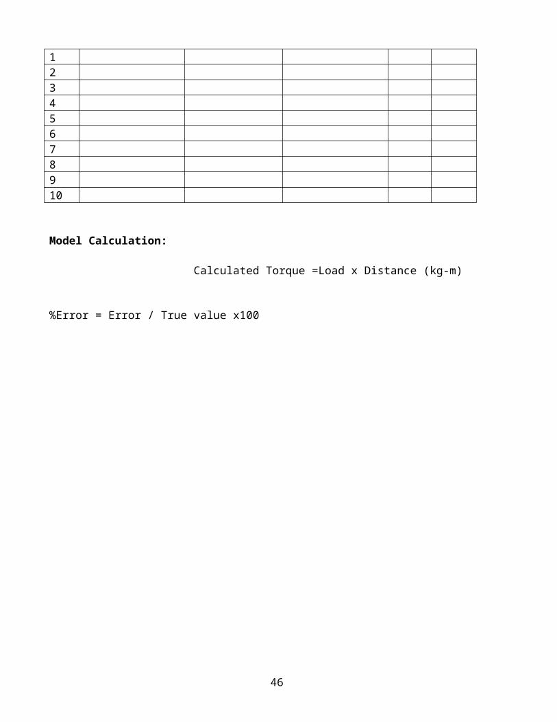
Model Calculation:
Calculated Torque =Load x Distance (kg-m)
%Error = Error / True value x100
36
Result: Thus measurement of torque using shear type load cell has been carried out.Graph:
Observed torque Vs Calculated torque VIVA QUESTIONS
1. Define Torque2. What is the purpose torque measurement?3. How to change a torque when distance is changed?4. What is transducer?5. Application of this instrument system.
37
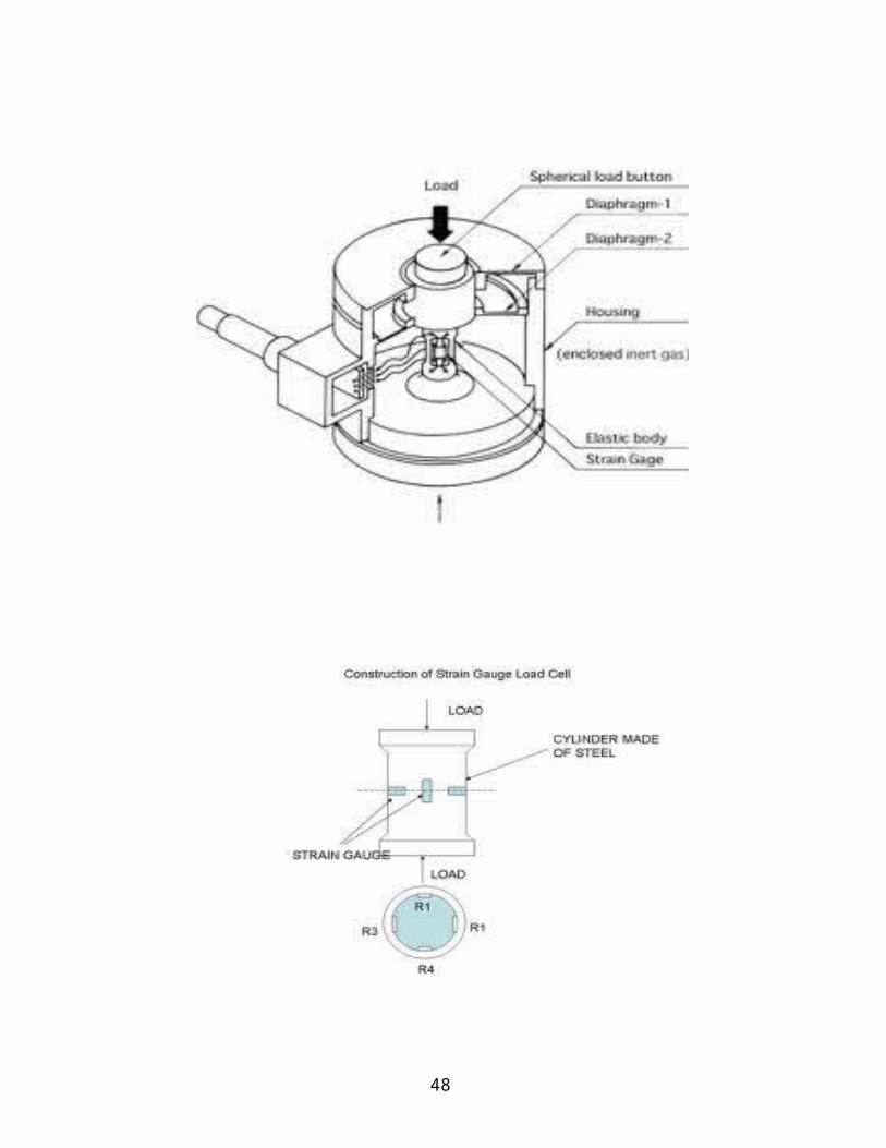
LOAD CELL
38
39

EX.NO:
DATE: FORCE MEASUREMENT
Aim:
To measure the force using load cell.
Apparatus Required:
1. Proving Ring2. Load cell3. Force indicator4. screw jack5. Dial gauge.
Capacity of proving Ring =2.5 KN.
Description :
Force is one of the major derived parameter having fundamental dimension of
mass length and time. It is a vector quantity which, when applied result in a change of momentum in a
body. Basically mechanical force is created due to variation of started potential energy.
This is different types of load cell like column type, shear type, s-type, and compression type.
In this setup, s-type load cell is provided.
Procedure:
1. Ensure that proving ring along with load all is perfectly in vertical position.
2. Check and ensure that the axis of screw jacks perfectly aligned with load cell.
3. Ensure that load cell with socket is connected to the rear side of the load indicator.
4. Apply a small load without any slip in the system.
5. Note down the reading of dial gauge of force indicator.
40
Table:
Sl.noActual load applied (kg)
Indicator Reading(kg)
Error %Error
12345678910
Model calculation:
%Error = Error / True value x100
41
Graph: Deflection Vs Applied load
Result: Thus the force measurement has been measured using load cell.
VIVA QUESTION
1. Range of instrument2. What is strain gauge?3. How is working strain gauge?4. Which is calibrating in this system?5. What are uses of zero and CAL adjustment?6. How do you measure error?7. How is working load cell?8. What are the steps followed in this system?
42
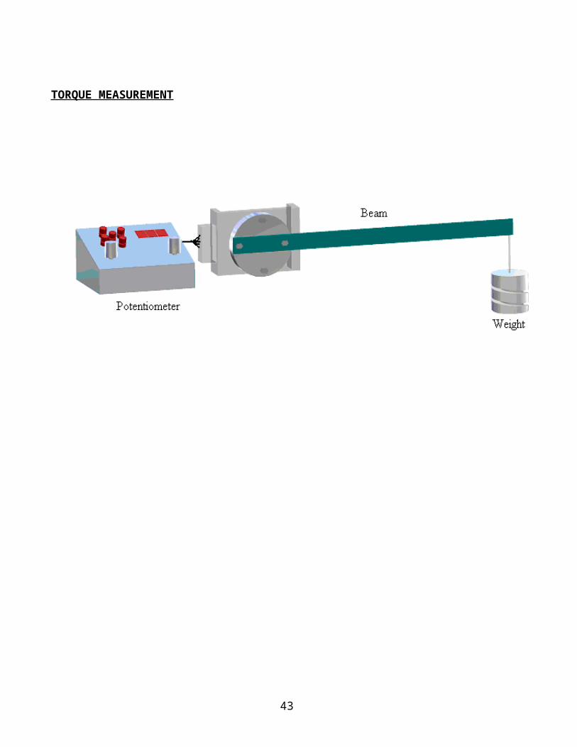
Table:
Sl.NoThermometer
Actual temperature °C (A) (Aaaaa ((A)
Thermocouple Indicated temperature C° (B)
Error( A - B )
12345678910
43
EX.NO:
DATE: TEMPERATURE MEASUREMENT
Aim:
To measure temperature using thermometer and thermocouple apparatus and compare the results.
Apparatus Required:
Temperature indicator Temperature source Thermocouple
Formula used :
Error = Va – Vi
% Error = Error
-------------- x 100 Va
Where Va is the actual temperature Vi is the thermocouple indicated temperature
Theory:
The basic principle of thermocouple is when two dissimilar metals are joined together an e.m.f will
exist between the two points A and Bewitch is primarily a function of the junction Temperature. The
above principle is called see back effectThe thermocouple consists of one hot junction and one cold
44
junction. The hot junction is introduced into the place where temperature is to be measured. The other
cold junction is maintained at constant reference temperature. Also one voltage measuring instrument is
connected to the free ends of the thermocouple. In thermocouple the known temperature is called
reference temperature. The temperature which is to be measured is introduced in the thermocouple hot
junction, A common arrangement for establishing the reference temperature is ice bath. The reference
temperature is controlled to be at a constant temperature is at 0º C.The temperature difference between
the Ice bath and the Hot junction temperature will create an e.m.f.This e.m.f production is measured in
the mill voltmeter. So this change in e.m.f rate will give the measure of temperature.
Procedure:
1. Clean the instrument and its accessories by fine cotton cloth.
2. Check connection made and switch on the instrument by rocker switch.
3. The display glows to indicate is on.
4. Allow the instruments in on position for 10 minutes for initial warm up.
5. Fill around 3/4th full of water to the kettle and place the thermometer and thermocouple Inside the kettle
6. Note down the initial water temperature from the thermometer.Adjustthe initial set potentiometer in the front panel till the display reads initial water temperature
7. Switch on the kettle and wait till the water boils note down the thermometer reading and set Potentiometer till the display reads boiling water temperature.
8. Remove the thermometer and temperature sensor from the Kettle and change the water and Replace the thermometer reading and set final set potentiometer till the display reads boiling Water Temperature.
9. Switch on the kettle and note down the reading for every 10 º interval and tabulate the readings
10. Plot the graphs between actual reading Vs indicator reading.
Graph: Indicated Temperature Vs Actual Temperature
45
Result: Thus the temperature is measured using thermocouple.
VIVA QUESTION
1) Which type Principle in thermocouple?2) What is thermoelectric effect?3) How to heat convert into voltage?4) Which is calibrating in this experiment?5) What are steps followed?6) Why do preferred water for testing of temperature?7) Mention the principle involved in bimetallic strip. 8) Which type Principle in thermocouple?
46
SURFACE FINISH MEASURING EQUIPMENT
47
EX.NO:
DATE: SURFACE FINISH MEASURING EQUIPMENT
AIM:
To measure the surface finish of a given specimen
APPARATUS:
PROCEDURE:
48

RESULT:
49