mgc3030 woodstar development kit user's guide€¦ · and india. the company’s quality...
TRANSCRIPT
2014-2015 Microchip Technology Inc. DS40001777B
MGC3030Woodstar Development Kit
User’s Guide
DS40001777B-page 2 2014-2015 Microchip Technology Inc.
Information contained in this publication regarding deviceapplications and the like is provided only for your convenienceand may be superseded by updates. It is your responsibility toensure that your application meets with your specifications.MICROCHIP MAKES NO REPRESENTATIONS ORWARRANTIES OF ANY KIND WHETHER EXPRESS ORIMPLIED, WRITTEN OR ORAL, STATUTORY OROTHERWISE, RELATED TO THE INFORMATION,INCLUDING BUT NOT LIMITED TO ITS CONDITION,QUALITY, PERFORMANCE, MERCHANTABILITY ORFITNESS FOR PURPOSE. Microchip disclaims all liabilityarising from this information and its use. Use of Microchipdevices in life support and/or safety applications is entirely atthe buyer’s risk, and the buyer agrees to defend, indemnify andhold harmless Microchip from any and all damages, claims,suits, or expenses resulting from such use. No licenses areconveyed, implicitly or otherwise, under any Microchipintellectual property rights.
Note the following details of the code protection feature on Microchip devices:
• Microchip products meet the specification contained in their particular Microchip Data Sheet.
• Microchip believes that its family of products is one of the most secure families of its kind on the market today, when used in the intended manner and under normal conditions.
• There are dishonest and possibly illegal methods used to breach the code protection feature. All of these methods, to our knowledge, require using the Microchip products in a manner outside the operating specifications contained in Microchip’s Data Sheets. Most likely, the person doing so is engaged in theft of intellectual property.
• Microchip is willing to work with the customer who is concerned about the integrity of their code.
• Neither Microchip nor any other semiconductor manufacturer can guarantee the security of their code. Code protection does not mean that we are guaranteeing the product as “unbreakable.”
Code protection is constantly evolving. We at Microchip are committed to continuously improving the code protection features of ourproducts. Attempts to break Microchip’s code protection feature may be a violation of the Digital Millennium Copyright Act. If such actsallow unauthorized access to your software or other copyrighted work, you may have a right to sue for relief under that Act.
Microchip received ISO/TS-16949:2009 certification for its worldwide headquarters, design and wafer fabrication facilities in Chandler and Tempe, Arizona; Gresham, Oregon and design centers in California and India. The Company’s quality system processes and procedures are for its PIC® MCUs and dsPIC® DSCs, KEELOQ® code hopping devices, Serial EEPROMs, microperipherals, nonvolatile memory and analog products. In addition, Microchip’s quality system for the design and manufacture of development systems is ISO 9001:2000 certified.
QUALITY MANAGEMENT SYSTEM CERTIFIED BY DNV
== ISO/TS 16949 ==
Trademarks
The Microchip name and logo, the Microchip logo, dsPIC, FlashFlex, flexPWR, JukeBlox, KEELOQ, KEELOQ logo, Kleer, LANCheck, MediaLB, MOST, MOST logo, MPLAB, OptoLyzer, PIC, PICSTART, PIC32 logo, RightTouch, SpyNIC, SST, SST Logo, SuperFlash and UNI/O are registered trademarks of Microchip Technology Incorporated in the U.S.A. and other countries.
The Embedded Control Solutions Company and mTouch are registered trademarks of Microchip Technology Incorporated in the U.S.A.
Analog-for-the-Digital Age, BodyCom, chipKIT, chipKIT logo, CodeGuard, dsPICDEM, dsPICDEM.net, ECAN, In-Circuit Serial Programming, ICSP, Inter-Chip Connectivity, KleerNet, KleerNet logo, MiWi, MPASM, MPF, MPLAB Certified logo, MPLIB, MPLINK, MultiTRAK, NetDetach, Omniscient Code Generation, PICDEM, PICDEM.net, PICkit, PICtail, RightTouch logo, REAL ICE, SQI, Serial Quad I/O, Total Endurance, TSHARC, USBCheck, VariSense, ViewSpan, WiperLock, Wireless DNA, and ZENA are trademarks of Microchip Technology Incorporated in the U.S.A. and other countries.
SQTP is a service mark of Microchip Technology Incorporated in the U.S.A.
Silicon Storage Technology is a registered trademark of Microchip Technology Inc. in other countries.
GestIC is a registered trademarks of Microchip Technology Germany II GmbH & Co. KG, a subsidiary of Microchip Technology Inc., in other countries.
All other trademarks mentioned herein are property of their respective companies.
© 2014-2015, Microchip Technology Incorporated, Printed in the U.S.A., All Rights Reserved.
ISBN: 978-1-63276-971-8

Object of Declaration: MGC3030 Woodstar Development Kit User’s Guide
2014-2015 Microchip Technology Inc. DS40001777B-page 3
MGC3030 Woodstar Development Kit User’s Guide
NOTES:
DS40001777B-page 4 2014-2015 Microchip Technology Inc.
MGC3030 WOODSTAR DEVELOPMENT
KIT USER’S GUIDETable of Contents
Preface ........................................................................................................................... 7Introduction............................................................................................................ 7
Document Layout .................................................................................................. 7
Conventions Used in this Guide ............................................................................ 8
Warranty Registration............................................................................................ 9
Recommended Reading........................................................................................ 9
The Microchip Web Site ...................................................................................... 10
Development Systems Customer Change Notification Service .......................... 10
Customer Support ............................................................................................... 11
Revision History .................................................................................................. 11
Chapter 1. Overview1.1 Introduction ................................................................................................... 131.2 Woodstar Concept and Deliverables ............................................................ 131.3 Woodstar Development Kit Package Content .............................................. 141.4 GestIC® Hardware References .................................................................... 151.5 Aurea Software Package .............................................................................. 161.6 MGC3030/3130 Software Development Kit (SDK) ....................................... 16
Chapter 2. Getting Started2.1 Prerequisites ................................................................................................ 172.2 Step 1: Development Kit Assembly .............................................................. 172.3 Step 2: Connecting the Woodstar Development Kit to the PC ..................... 182.4 Step 3: Installing Windows® CDC Driver ...................................................... 182.5 Step 4: Starting Aurea GUI ........................................................................... 18
Chapter 3. Woodstar Boards – Hardware Description3.1 Overview ...................................................................................................... 21
3.1.1 I2C™ to USB Bridge .................................................................................. 213.1.2 MGC3030 Unit ........................................................................................... 213.1.3 95x60 mm Reference Electrode PCB ........................................................ 21
3.2 The MGC3030 Unit ...................................................................................... 223.3 95x60 mm Reference Electrode .................................................................. 233.4 I2C™ to USB Bridge .................................................................................... 25
Chapter 4. System Integration Using Woodstar4.1 Introduction ................................................................................................... 274.2 Integration Examples .................................................................................... 27
2014-2015 Microchip Technology Inc. DS40001777B-page 5

MGC3030 Woodstar Development Kit User’s Guide
Chapter 5. Troubleshooting5.1 Power LED Does Not Illuminate ................................................................... 315.2 LED 1 Blinks Fast ........................................................................................ 315.3 Signal Streaming Stops ................................................................................ 315.4 Electrode Signals are Zero ........................................................................... 315.5 LED 1 and 2 on I2C to USB Bridge are OFF ................................................ 32
Appendix A. SchematicsA.1 Introduction .................................................................................................. 33A.2 Bill of Materials ............................................................................................. 33A.3 Board Schematics and Layout ..................................................................... 35
Appendix B. Sensitivity Profile and CapacitancesB.1 Introduction .................................................................................................. 39B.2 Sensitivity Profiles ........................................................................................ 39B.3 Electrode Capacities .................................................................................... 40
Appendix C. Driver Installation ManualC.1 Open Device Manager ................................................................................. 41C.2 Select Device ............................................................................................... 41C.3 Locate Driver ............................................................................................... 42C.4 Verify Communication .................................................................................. 42
Appendix D. Glossary
Worldwide Sales and Service .....................................................................................45
DS40001777B-page 6 2014-2015 Microchip Technology Inc.

MGC3030 WOODSTAR DEVELOPMENT
KIT USER’S GUIDEPreface
INTRODUCTION
This chapter contains general information that will be useful to know before using theMGC3030 Woodstar Development Kit. Items discussed in this chapter include:
• Document Layout
• Conventions Used in this Guide
• Warranty Registration
• Recommended Reading
• The Microchip Web Site
• Development Systems Customer Change Notification Service
• Customer Support
• Revision History
DOCUMENT LAYOUT
This document describes the installation and use of the MGC3030 WoodstarDevelopment Kit. The document is organized as follows:
• Chapter 1. “Overview”
• Chapter 2. “Getting Started”
• Chapter 3. “Woodstar Boards – Hardware Description”
• Chapter 4. “System Integration Using Woodstar”
• Chapter 5. “Troubleshooting”
• Appendix A. “Schematics”
• Appendix B. “Sensitivity Profile and Capacitances”
• Appendix C. “Driver Installation Manual”
• Appendix D. “Glossary”
NOTICE TO CUSTOMERS
All documentation becomes dated, and this manual is no exception. Microchip tools and documentation are constantly evolving to meet customer needs, so some actual dialogs and/or tool descriptions may differ from those in this document. Please refer to our web site (www.microchip.com) to obtain the latest documentation available.
Documents are identified with a “DS” number. This number is located on the bottom of each page, in front of the page number. The numbering convention for the DS number is “DSXXXXXA”, where “XXXXX” is the document number and “A” is the revision level of the document.
For the most up-to-date information on development tools, see the MPLAB® IDE online help. Select the Help menu, and then Topics to open a list of available online help files.
2014-2015 Microchip Technology Inc. DS40001777B-page 7

MGC3030 Woodstar Development Kit User’s Guide
CONVENTIONS USED IN THIS GUIDE
This manual uses the following documentation conventions:
DOCUMENTATION CONVENTIONS
Description Represents Examples
Arial font:
Italic characters Referenced books MPLAB® IDE User’s Guide
Emphasized text ...is the only compiler...
Initial caps A window the Output window
A dialog the Settings dialog
A menu selection select Enable Programmer
Quotes A field name in a window or dialog
“Save project before build”
Underlined, italic text with right angle bracket
A menu path File>Save
Bold characters A dialog button Click OK
A tab Click the Power tab
N‘Rnnnn A number in verilog format, where N is the total number of digits, R is the radix and n is a digit.
4‘b0010, 2‘hF1
Text in angle brackets < > A key on the keyboard Press <Enter>, <F1>
Courier New font:
Plain Courier New Sample source code #define START
Filenames autoexec.bat
File paths c:\mcc18\h
Keywords _asm, _endasm, static
Command-line options -Opa+, -Opa-
Bit values 0, 1
Constants 0xFF, ‘A’
Italic Courier New A variable argument file.o, where file can be any valid filename
Square brackets [ ] Optional arguments mcc18 [options] file [options]
Curly brackets and pipe character: |
Choice of mutually exclusive arguments; an OR selection
errorlevel 0|1
Ellipses... Replaces repeated text var_name [, var_name...]
Represents code supplied by user
void main (void) ...
DS40001777B-page 8 2014-2015 Microchip Technology Inc.

Preface
WARRANTY REGISTRATION
Please complete the enclosed Warranty Registration Card and mail it promptly.Sending in the Warranty Registration Card entitles users to receive new productupdates. Interim software releases are available at the Microchip web site.
RECOMMENDED READING
This user’s guide describes how to use the MGC3030 Woodstar Development Kit.Other useful documents are listed below. The following Microchip documents areavailable and recommended as supplemental reference resources.
• “GestIC® Design Guide” (DS40001716). This document describes theMGC3030/MGC3130 system characteristic parameters and the design process. Itenables the user to generate a good electrode design and to parameterize the fullGestIC® system.
• “MGC3030/3130 GestIC® Library Interface Description User’s Guide”(DS40001718). This document is the interface description of theMGC3030/MGC3130 GestIC Library. It outlines the function of the Library’smessage interface, and contains the complete message reference to control andoperate the MGC3030/MGC3130 system.
• “MGC3030/3130 3D Gesture Controller Data Sheet” (DS40001667). Consult thisdocument for information regarding the MGC3030/MGC3130 3D Tracking andGesture Controller.
• “Aurea Graphical User Interface User’s Guide” (DS40001681). This documentdescribes how to use the Aurea Graphical User Interface.
2014-2015 Microchip Technology Inc. DS40001777B-page 9

MGC3030 Woodstar Development Kit User’s Guide
THE MICROCHIP WEB SITE
Microchip provides online support via our web site at www.microchip.com. This website is used as a means to make files and information easily available to customers.Accessible by using your favorite Internet browser, the web site contains the followinginformation:
• Product Support – Data sheets and errata, application notes and sampleprograms, design resources, user’s guides and hardware support documents,latest software releases and archived software
• General Technical Support – Frequently Asked Questions (FAQs), technicalsupport requests, online discussion groups, Microchip consultant programmember listing
• Business of Microchip – Product selector and ordering guides, latest Microchippress releases, listing of seminars and events, listings of Microchip sales offices,distributors and factory representatives
DEVELOPMENT SYSTEMS CUSTOMER CHANGE NOTIFICATION SERVICE
Microchip’s customer notification service helps keep customers current on Microchipproducts. Subscribers will receive e-mail notification whenever there are changes,updates, revisions or errata related to a specified product family or development tool ofinterest.
To register, access the Microchip web site at www.microchip.com, click on CustomerChange Notification and follow the registration instructions.
The Development Systems product group categories are:
• Compilers – The latest information on Microchip C compilers, assemblers, linkersand other language tools. These include all MPLAB® C compilers; all MPLABassemblers (including MPASM™ assembler); all MPLAB linkers (includingMPLINK™ object linker); and all MPLAB librarians (including MPLIB™ objectlibrarian).
• Emulators – The latest information on Microchip in-circuit emulators.Thisincludes the MPLAB REAL ICE™ and MPLAB ICE 2000 in-circuit emulators.
• In-Circuit Debuggers – The latest information on the Microchip in-circuitdebuggers. This includes MPLAB ICD 3 in-circuit debuggers and PICkit™ 3debug express.
• MPLAB® IDE – The latest information on Microchip MPLAB IDE, the Windows®
Integrated Development Environment for development systems tools. This list isfocused on the MPLAB IDE, MPLAB IDE Project Manager, MPLAB Editor andMPLAB SIM simulator, as well as general editing and debugging features.
• Programmers – The latest information on Microchip programmers. These includeproduction programmers such as MPLAB REAL ICE in-circuit emulator, MPLABICD 3 in-circuit debugger and MPLAB PM3 device programmers. Also includedare nonproduction development programmers such as PICSTART® Plus andPICkit 2 and 3.
DS40001777B-page 10 2014-2015 Microchip Technology Inc.

Preface
CUSTOMER SUPPORT
Users of Microchip products can receive assistance through several channels:
• Distributor or Representative
• Local Sales Office
• Field Application Engineer (FAE)
• Technical Support
Customers should contact their distributor, representative or field application engineer(FAE) for support. Local sales offices are also available to help customers. A listing ofsales offices and locations is included in the back of this document.
Technical support is available through the web site at:
http://www.microchip.com/support.
REVISION HISTORY
Revision A (November, 2014)
Initial release of the document.
Revision B (January, 2015)
Updated the Recommended Reading section; Other minor corrections.
2014-2015 Microchip Technology Inc. DS40001777B-page 11

MGC3030 Woodstar Development Kit User’s Guide
NOTES:
DS40001777B-page 12 2014-2015 Microchip Technology Inc.

MGC3030 WOODSTAR DEVELOPMENT
KIT USER’S GUIDEChapter 1. Overview
1.1 INTRODUCTION
MGC3030 is a product based on Microchip’s patented GestIC® technology. It isdeveloped as a mixed-signal controller. MGC3030 has one transmit and five verysensitive receive channels that are capable of detecting changes of a transmittedelectrical field (E-field) corresponding to capacitive changes in the femtofarad(1 fF = 10-15F) range.
In order to transmit and receive an electrical field, electrodes have to be connected tothe transmitting and receiving channels of the MGC3030 controller. The spatialarrangement of the electrodes allows the chip to determine the center of gravity of theelectric field distortion, and thus gesture recognition of a user’s hand in the detectionspace.
1.2 WOODSTAR CONCEPT AND DELIVERABLES
The Woodstar Development Kit is designed to support an easy integration ofMicrochip’s MGC3030 3D Gesture Controller into the customer’s applications. Itprovides MGC3030 system setup, related hardware and software references:
• Aurea Software Package with the Aurea Graphical User Interface and GestIC Library
• MGC3030/3130 Software Development Kit (SDK)
• MGC3030/3130 PIC18 Host Reference code
With the help of these tools, the design-in process can be easily performed in fivesteps:
1. Feature Definition
2. Electrode Design
3. MGC3030 Parameterization
4. Host Application Programming
5. Verification
Tutorial videos for the design-in process can be found on www.microchip.com/videohmidtutorials.
Woodstar hardware builds a complete MGC3030 reference system consisting of threeindividual PCBs:
• MGC3030 Unit
• I2C™ to USB Bridge
• Reference Electrode with a 95x60 mm sensitive area
2014-2015 Microchip Technology Inc. DS40001777B-page 13

MGC3030 Woodstar Development Kit User’s Guide
It can be plugged to a PC via a USB cable and used for evaluation of the MGC3030chip and the GestIC technology. During the customer’s design-in process the individualboards can be combined according to the customer’s needs.
Three examples are given below:
• Combine the MGC3030 unit and the I2C to USB bridge to evaluate customizedelectrodes
• Use the I2C to USB bridge to parameterize and debug the MGC3030 applicationcircuitry in the customer’s design
• Combine the MGC3030 unit and electrodes to develop gesture-drivenapplications for PC-based or embedded software environments
1.3 WOODSTAR DEVELOPMENT KIT PACKAGE CONTENT
The Woodstar Development Kit package content is listed below:
• MGC3030 Module
• I2C to USB Bridge Module
• Reference Electrode (95x60 mm sensitive area)
• USB Cable for PC Connection
FIGURE 1-1: WOODSTAR DEVELOPMENT KIT
DS40001777B-page 14 2014-2015 Microchip Technology Inc.
Overview
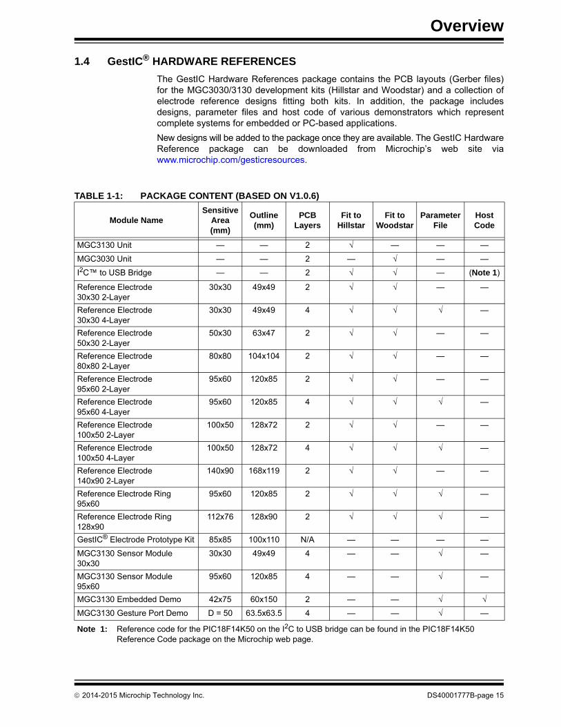
1.4 GestIC® HARDWARE REFERENCES
The GestIC Hardware References package contains the PCB layouts (Gerber files)for the MGC3030/3130 development kits (Hillstar and Woodstar) and a collection ofelectrode reference designs fitting both kits. In addition, the package includesdesigns, parameter files and host code of various demonstrators which representcomplete systems for embedded or PC-based applications.
New designs will be added to the package once they are available. The GestIC HardwareReference package can be downloaded from Microchip’s web site viawww.microchip.com/gesticresources.
TABLE 1-1: PACKAGE CONTENT (BASED ON V1.0.6)
Module NameSensitive
Area (mm)
Outline (mm)
PCB Layers
Fit to Hillstar
Fit to Woodstar
Parameter File
Host Code
MGC3130 Unit — — 2 √ — — —
MGC3030 Unit — — 2 — √ — —
I2C™ to USB Bridge — — 2 √ √ — (Note 1)
Reference Electrode 30x30 2-Layer
30x30 49x49 2 √ √ — —
Reference Electrode 30x30 4-Layer
30x30 49x49 4 √ √ √ —
Reference Electrode 50x30 2-Layer
50x30 63x47 2 √ √ — —
Reference Electrode 80x80 2-Layer
80x80 104x104 2 √ √ — —
Reference Electrode 95x60 2-Layer
95x60 120x85 2 √ √ — —
Reference Electrode 95x60 4-Layer
95x60 120x85 4 √ √ √ —
Reference Electrode 100x50 2-Layer
100x50 128x72 2 √ √ — —
Reference Electrode 100x50 4-Layer
100x50 128x72 4 √ √ √ —
Reference Electrode 140x90 2-Layer
140x90 168x119 2 √ √ — —
Reference Electrode Ring 95x60
95x60 120x85 2 √ √ √ —
Reference Electrode Ring 128x90
112x76 128x90 2 √ √ √ —
GestIC® Electrode Prototype Kit 85x85 100x110 N/A — — — —
MGC3130 Sensor Module 30x30
30x30 49x49 4 — — √ —
MGC3130 Sensor Module 95x60
95x60 120x85 4 — — √ —
MGC3130 Embedded Demo 42x75 60x150 2 — — √ √
MGC3130 Gesture Port Demo D = 50 63.5x63.5 4 — — √ —
Note 1: Reference code for the PIC18F14K50 on the I2C to USB bridge can be found in the PIC18F14K50 Reference Code package on the Microchip web page.
2014-2015 Microchip Technology Inc. DS40001777B-page 15

MGC3030 Woodstar Development Kit User’s Guide
1.5 AUREA SOFTWARE PACKAGE
The Aurea Software Package contains all relevant system software anddocumentation. The Woodstar Development Kit is supported by Aurea SoftwarePackage V1.2 onwards.
The package contains:
• Aurea PC Software
• GestIC Library (firmware) Binary File
• GestIC Parameterization Files
• Windows® CDC Driver
• Documentation
The latest Aurea Software Package can be downloaded from Microchip’s web site viawww.microchip.com/gesticresources.
Please find a collection of GestIC/Aurea tutorial videos atwww.microchip.com/videohmidtutorials.
1.6 MGC3030/3130 SOFTWARE DEVELOPMENT KIT (SDK)
The MGC3030/3130 Software Development Kit (SDK) supports the integration ofMGC3030 into a software environment. Thus, it includes a C reference code for GestICAPI, a precompiled library for Windows operating systems, and a demo applicationusing the GestIC API interface.
Woodstar Development Kit is supported by MGC3030/3130 SDK V1.1 onwards.
The latest SDK can be downloaded from Microchip’s web site viawww.microchip.com/gesticresources.
DS40001777B-page 16 2014-2015 Microchip Technology Inc.

MGC3030 WOODSTAR DEVELOPMENT
KIT USER’S GUIDEChapter 2. Getting Started
The Woodstar Development Kit can be used as a stand-alone GestIC system andevaluated in conjunction with the Aurea PC software. This section describes how to getstarted.
2.1 PREREQUISITES
The following prerequisites have to be fulfilled:
• PC with Windows 7 or Windows 8 operating systems, USB port and minimumscreen resolution of 1024x768
• Woodstar Development Kit (MGC3030 unit, I2C to USB bridge, 95x60 mm frameelectrode)
• Aurea Software Package V1.2 onwards
The Aurea Software Package is available as .zip file. Unzip the file, run setup.exeand install the package to the PC. The folder structure is as shown in Figure 2-1.
FIGURE 2-1: FOLDER STRUCTURE
2.2 STEP 1: DEVELOPMENT KIT ASSEMBLY
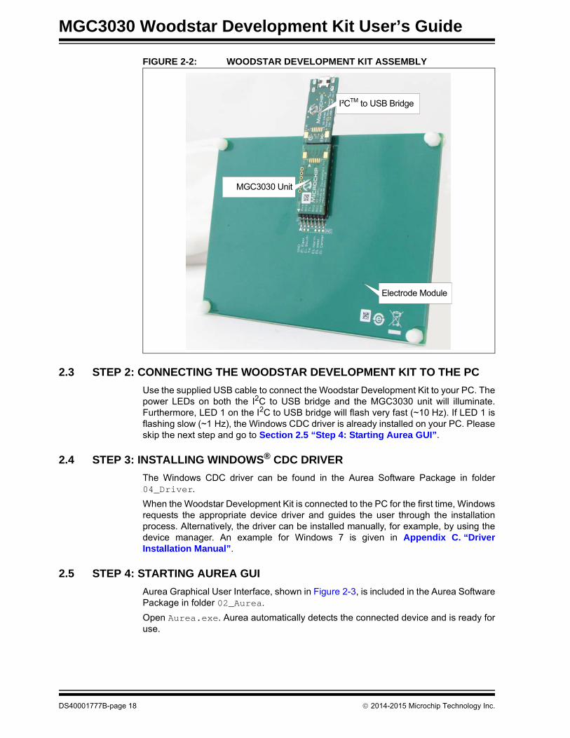
Connect the electrodes, the MGC3030 unit and the I2C to USB bridge as shown inFigure 2-2.
Note: Make sure the MGC3030 unit and the I2C to USB bridge are already connected before plugging in the USB connection.
2014-2015 Microchip Technology Inc. DS40001777B-page 17
MGC3030 Woodstar Development Kit User’s Guide
FIGURE 2-2: WOODSTAR DEVELOPMENT KIT ASSEMBLY
2.3 STEP 2: CONNECTING THE WOODSTAR DEVELOPMENT KIT TO THE PC
Use the supplied USB cable to connect the Woodstar Development Kit to your PC. Thepower LEDs on both the I2C to USB bridge and the MGC3030 unit will illuminate.Furthermore, LED 1 on the I2C to USB bridge will flash very fast (~10 Hz). If LED 1 isflashing slow (~1 Hz), the Windows CDC driver is already installed on your PC. Pleaseskip the next step and go to Section 2.5 “Step 4: Starting Aurea GUI”.
2.4 STEP 3: INSTALLING WINDOWS® CDC DRIVER
The Windows CDC driver can be found in the Aurea Software Package in folder04_Driver.
When the Woodstar Development Kit is connected to the PC for the first time, Windowsrequests the appropriate device driver and guides the user through the installationprocess. Alternatively, the driver can be installed manually, for example, by using thedevice manager. An example for Windows 7 is given in Appendix C. “DriverInstallation Manual”.
2.5 STEP 4: STARTING AUREA GUI
Aurea Graphical User Interface, shown in Figure 2-3, is included in the Aurea SoftwarePackage in folder 02_Aurea.
Open Aurea.exe. Aurea automatically detects the connected device and is ready foruse.
Electrode Module
I²CTM to USB Bridge
MGC3030 Unit
DS40001777B-page 18 2014-2015 Microchip Technology Inc.
Getting Started
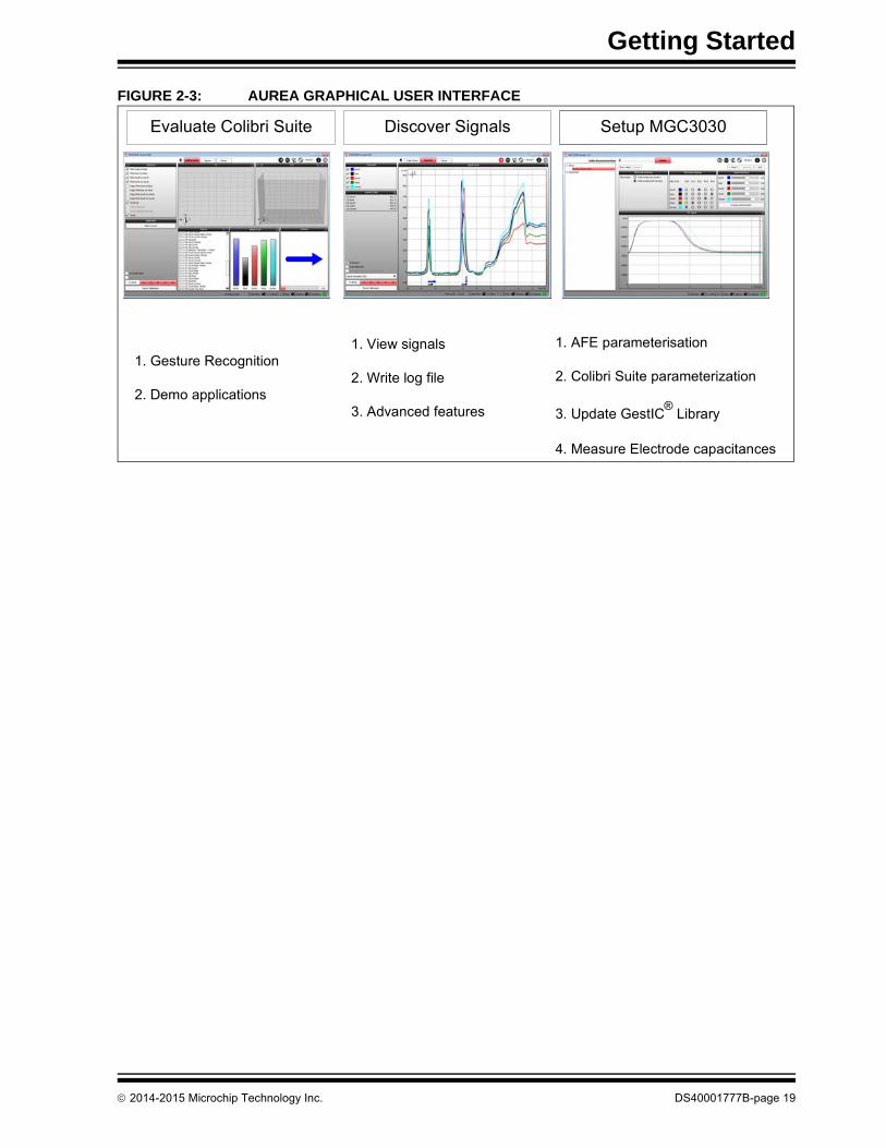
FIGURE 2-3: AUREA GRAPHICAL USER INTERFACE
Evaluate Colibri Suite Discover Signals Setup MGC3030
1. Gesture Recognition
2. Demo applications
1. View signals
2. Write log file
3. Advanced features
1. AFE parameterisation
2. Colibri Suite parameterization
3. Update GestIC®
Library
4. Measure Electrode capacitances
2014-2015 Microchip Technology Inc. DS40001777B-page 19

MGC3030 Woodstar Development Kit User’s Guide
NOTES:
DS40001777B-page 20 2014-2015 Microchip Technology Inc.
MGC3030 WOODSTAR DEVELOPMENT
KIT USER’S GUIDEChapter 3. Woodstar Boards – Hardware Description
3.1 OVERVIEW
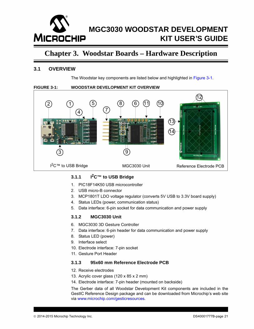
The Woodstar key components are listed below and highlighted in Figure 3-1.
FIGURE 3-1: WOODSTAR DEVELOPMENT KIT OVERVIEW
3.1.1 I2C™ to USB Bridge
1. PIC18F14K50 USB microcontroller
2. USB micro-B connector
3. MCP1801T LDO voltage regulator (converts 5V USB to 3.3V board supply)
4. Status LEDs (power, communication status)
5. Data interface: 6-pin socket for data communication and power supply
3.1.2 MGC3030 Unit
6. MGC3030 3D Gesture Controller
7. Data interface: 6-pin header for data communication and power supply
8. Status LED (power)
9. Interface select
10. Electrode interface: 7-pin socket
11. Gesture Port Header
3.1.3 95x60 mm Reference Electrode PCB
12. Receive electrodes
13. Acrylic cover glass (120 x 85 x 2 mm)
14. Electrode interface: 7-pin header (mounted on backside)
The Gerber data of all Woodstar Development Kit components are included in theGestIC Reference Design package and can be downloaded from Microchip’s web sitevia www.microchip.com/gesticresources.
I2C™ to USB Bridge MGC3030 Unit Reference Electrode PCB
1
3 9
682
4
57
1012
14
13
11
2014-2015 Microchip Technology Inc. DS40001777B-page 21
MGC3030 Woodstar Development Kit User’s Guide
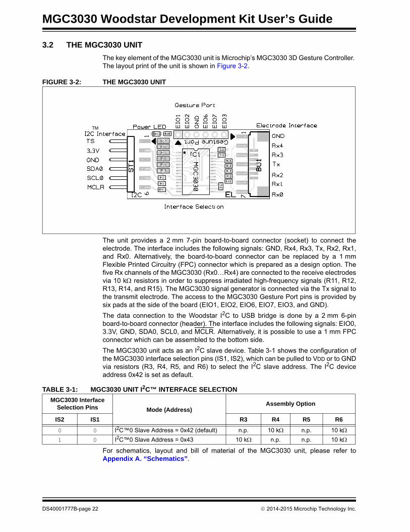
3.2 THE MGC3030 UNIT
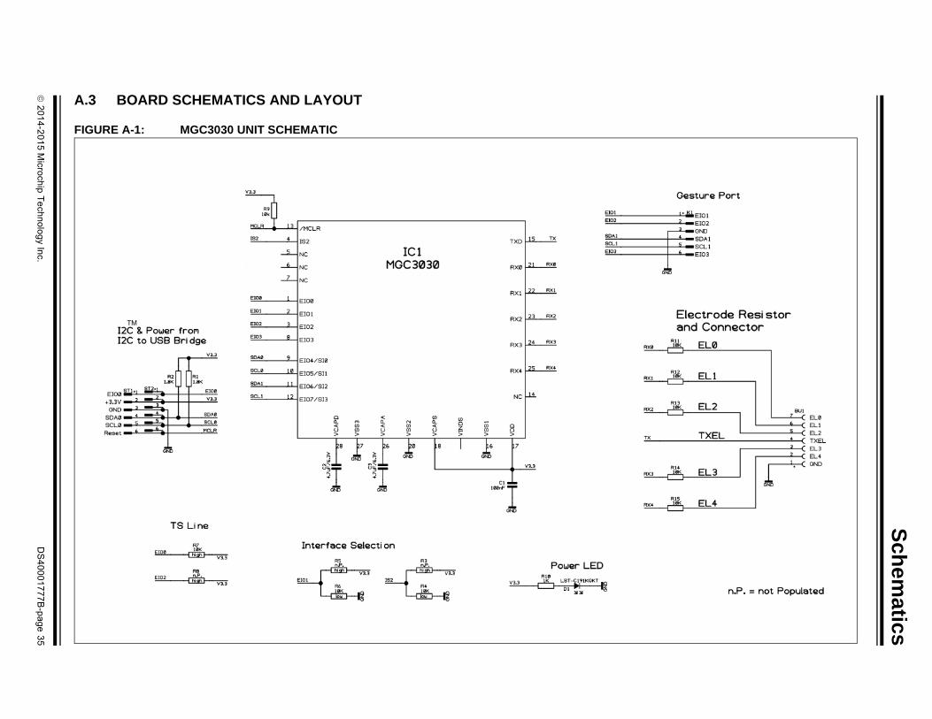
The key element of the MGC3030 unit is Microchip’s MGC3030 3D Gesture Controller. The layout print of the unit is shown in Figure 3-2.
FIGURE 3-2: THE MGC3030 UNIT
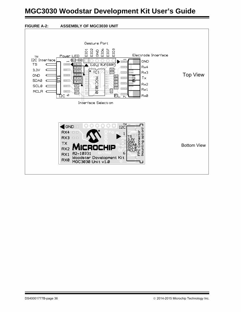
The unit provides a 2 mm 7-pin board-to-board connector (socket) to connect theelectrode. The interface includes the following signals: GND, Rx4, Rx3, Tx, Rx2, Rx1,and Rx0. Alternatively, the board-to-board connector can be replaced by a 1 mmFlexible Printed Circuitry (FPC) connector which is prepared as a design option. Thefive Rx channels of the MGC3030 (Rx0…Rx4) are connected to the receive electrodesvia 10 k resistors in order to suppress irradiated high-frequency signals (R11, R12,R13, R14, and R15). The MGC3030 signal generator is connected via the Tx signal tothe transmit electrode. The access to the MGC3030 Gesture Port pins is provided bysix pads at the side of the board (EIO1, EIO2, EIO6, EIO7, EIO3, and GND).
The data connection to the Woodstar I2C to USB bridge is done by a 2 mm 6-pinboard-to-board connector (header). The interface includes the following signals: EIO0,3.3V, GND, SDA0, SCL0, and MCLR. Alternatively, it is possible to use a 1 mm FPCconnector which can be assembled to the bottom side.
The MGC3030 unit acts as an I2C slave device. Table 3-1 shows the configuration ofthe MGC3030 interface selection pins (IS1, IS2), which can be pulled to VDD or to GNDvia resistors (R3, R4, R5, and R6) to select the I2C slave address. The I2C deviceaddress 0x42 is set as default.
For schematics, layout and bill of material of the MGC3030 unit, please refer toAppendix A. “Schematics”.
TM
TABLE 3-1: MGC3030 UNIT I2C™ INTERFACE SELECTION
MGC3030 Interface Selection Pins Mode (Address)
Assembly Option
IS2 IS1 R3 R4 R5 R6
0 0 I2C™0 Slave Address = 0x42 (default) n.p. 10 k n.p. 10 k
1 0 I2C™0 Slave Address = 0x43 10 k n.p. n.p. 10 k
DS40001777B-page 22 2014-2015 Microchip Technology Inc.

Woodstar Boards – Hardware Description
3.3 95x60 mm REFERENCE ELECTRODE
The 95x60 mm reference electrode provided with the Woodstar Development Kitconsists of one Tx and a set of five Rx electrodes (north, east, south, west, center),which are placed in two different layers. An additional ground layer is placedunderneath the Tx electrode to shield the electrode’s back from external influences.
FIGURE 3-3: ELECTRODE LAYOUT
The PCB is connected to the MGC3030 unit by the 2 mm 7-pin board-to-boardconnector. The interface includes the following signals: GND, Rx4, Rx3, Tx, Rx2, Rx1,and Rx0.
The dimension of the board is 120 x 85 mm; the sensitive area is 95 x 60 mm.
The five Rx electrodes include four frame electrodes and one center electrode, asshown in Figure 3-3. The frame electrodes are named according to their cardinaldirections: North, East, South and West. The dimensions of the four Rx frameelectrodes define the maximum sensing area. The center electrode is structured(cross-hatched) to get a similar input signal level as the four frame electrodes.
The Tx electrode spans over the complete area underneath the Rx electrodes. It iscross-hatched to reduce the capacitance between Rx and Tx (CRxTx). The Tx areaunderneath the center electrode covers 50% of the copper plane, the area around thecenter electrode covers only 20%.
The Rx feeding lines are embedded into the Tx electrode in the third layer (refer toFigure 3-4 and Figure 3-5). This supports shielding of the feeding lines. Dimensionsare given in Table 3-2.
2014-2015 Microchip Technology Inc. DS40001777B-page 23

MGC3030 Woodstar Development Kit User’s Guide
FIGURE 3-4: ELECTRODE LAYOUT
The electrode PCB is based on a 4-layer PCB design using FR4 material. Threefunctional layers are used:
• Layer 1 (Top): Rx electrodes
• Layer 3: Tx electrode and Rx feeding lines
• Layer 4 (Bottom): Ground
Layer 2 is not used.
TABLE 3-2: WOODSTAR ELECTRODE DIMENSIONS
Part Length Width Design
Horizontal Electrodes (Rx) 91.7 mm 5 mm Solid
Vertical Electrodes (Rx) 70.5 mm 5 mm Solid
Center Electrode (Rx) 85.7 mm 50.5 mm 3% cross-hatched
Tx Electrode (refer to Figure 3-4)Part I (under center electrode)Part II (outside Part I)
120 mm85.7 mm120 mm
85 mm50.5 mm85 mm
50% cross-hatched20% cross-hatched
Ground Area 120 mm 85 mm Solid
DS40001777B-page 24 2014-2015 Microchip Technology Inc.

Woodstar Boards – Hardware Description
FIGURE 3-5: PCB LAYER STACK
In a target system design the GND layer is not required. It is added for the Woodstarsensing electrode as a shielding layer and shall simulate the presence of staticcomponents which are placed in a target device underneath the sensing electrodes.
3.4 I2C TO USB BRIDGE
Connecting the MGC3030 unit to a PC requires an I2C to USB bridge. The GestICbridge works as a composite device class (CDC). It controls the USB transfer towardsthe host PC and handles the I2C communication with the MGC3030 unit. Moreover, itprovides 3.3V power supply and the MCLR signal to the MGC3030 unit.
The bridge function is handled by Microchip’s PIC18F14K50 USB microcontroller.
The board is equipped with a micro-USB connector (Type B) and a 2 mm 6-pin femaleboard-to-board connector for the I2C interface. The interface to the MGC3030 unitincludes the following signals: EIO0, 3.3V, GND, SDA0, SCL0, and MCLR. Please referto Figure 3-6.
FIGURE 3-6: I2C™ TO USB BRIDGE
Tx: 35 µm Tx
Rx : 18 µm
GND: 18 µm
Not Used: 35 µm
0.25 mm
0.15 mm
935
µm54
0µm
1.54
6m
m
Top layer
Bottomlayer
2nd layer
3rd layer
Rx feeding line
Note: Please refer to the “GestIC® Design Guide” for the electrodes equivalent circuitry, capacitances (CRxTx, CRxG, TxRxG) and their typical values.
N/C
CL
K
DA
TG
ND
VD
D
VP
P
ICSPTM Interface
Mic
ro U
SB
In
terf
ace
2014-2015 Microchip Technology Inc. DS40001777B-page 25
MGC3030 Woodstar Development Kit User’s Guide
The I2C to USB bridge is powered via the USB port. Microchip’s Low Dropout (LDO)Voltage Regulator MCP1801 is used to transform the 5V USB power to 3.3V requiredfor the PIC18F14K50. By default, 3.3V are also routed to the MGC3030 unit via the I2Cinterface. The 3.3V power supply towards the MGC3030 unit can be cut by removingthe 0 resistor R7.
The LEDs indicate the following:
• Power – signals that the I2C to USB bridge is powered (3.3V)
• LED1 blinks fast (~10 Hz) – indicates that there is no USB connection established• LED1 blinks slow (~1 Hz) – indicates that the USB connection is established
• LED 2 is ON when there is data on the I2C bus
• LED 2 is OFF when there is no data on the I2C bus
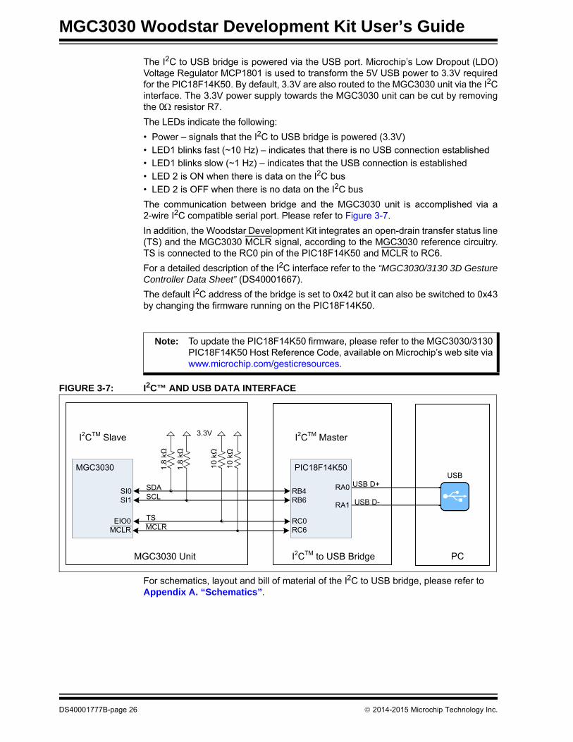
The communication between bridge and the MGC3030 unit is accomplished via a2-wire I2C compatible serial port. Please refer to Figure 3-7.
In addition, the Woodstar Development Kit integrates an open-drain transfer status line(TS) and the MGC3030 MCLR signal, according to the MGC3030 reference circuitry.TS is connected to the RC0 pin of the PIC18F14K50 and MCLR to RC6.
For a detailed description of the I2C interface refer to the “MGC3030/3130 3D GestureController Data Sheet” (DS40001667).
The default I2C address of the bridge is set to 0x42 but it can also be switched to 0x43by changing the firmware running on the PIC18F14K50.
FIGURE 3-7: I2C™ AND USB DATA INTERFACE
For schematics, layout and bill of material of the I2C to USB bridge, please refer to Appendix A. “Schematics”.
Note: To update the PIC18F14K50 firmware, please refer to the MGC3030/3130 PIC18F14K50 Host Reference Code, available on Microchip’s web site via www.microchip.com/gesticresources.
PIC18F14K50
RB4RB6
RC0RC6
RA0
RA1
SDASCL
TS
3.3V
1.8
kΩ
10kΩ
1.8
kΩ
MCLR
10kΩ
MGC3030
SI0SI1
EIO0MCLR
I2CTM to USB BridgeMGC3030 Unit
USB D+
USB D-
USB
I2CTM MasterI2CTM Slave
PC
DS40001777B-page 26 2014-2015 Microchip Technology Inc.

MGC3030 WOODSTAR DEVELOPMENT
KIT USER’S GUIDEChapter 4. System Integration Using Woodstar
4.1 INTRODUCTION
The Woodstar Development Kit is designed to support an easy integration ofMicrochip’s MGC3030 3D Gesture Controller into the customer’s applications.
The three Woodstar PCBs can be plugged to a PC via a USB cable and used forevaluation of the MGC3030 chip and the GestIC technology.
During the customer’s design-in process the individual boards can be combinedaccording to the customer’s needs.
Three examples are given below:
• Combine MGC3030 unit and I2C to USB bridge to evaluate customized electrodes• Use I2C to USB bridge to parameterize and debug the MGC3030 application
circuitry in the customer’s design (in-circuit)• Combine MGC3030 unit and electrodes to develop gesture-driven applications for
PC-based or embedded software environments
For in-circuit parameterization and debugging it is mandatory to control the MGC3030unit via Aurea Control Software. For that purpose, the customer’s application shouldprovide an appropriate hardware or software interface.
4.2 INTEGRATION EXAMPLES
The following figures show typical hardware circuits for the integration of MGC3030 intoa customer’s application.
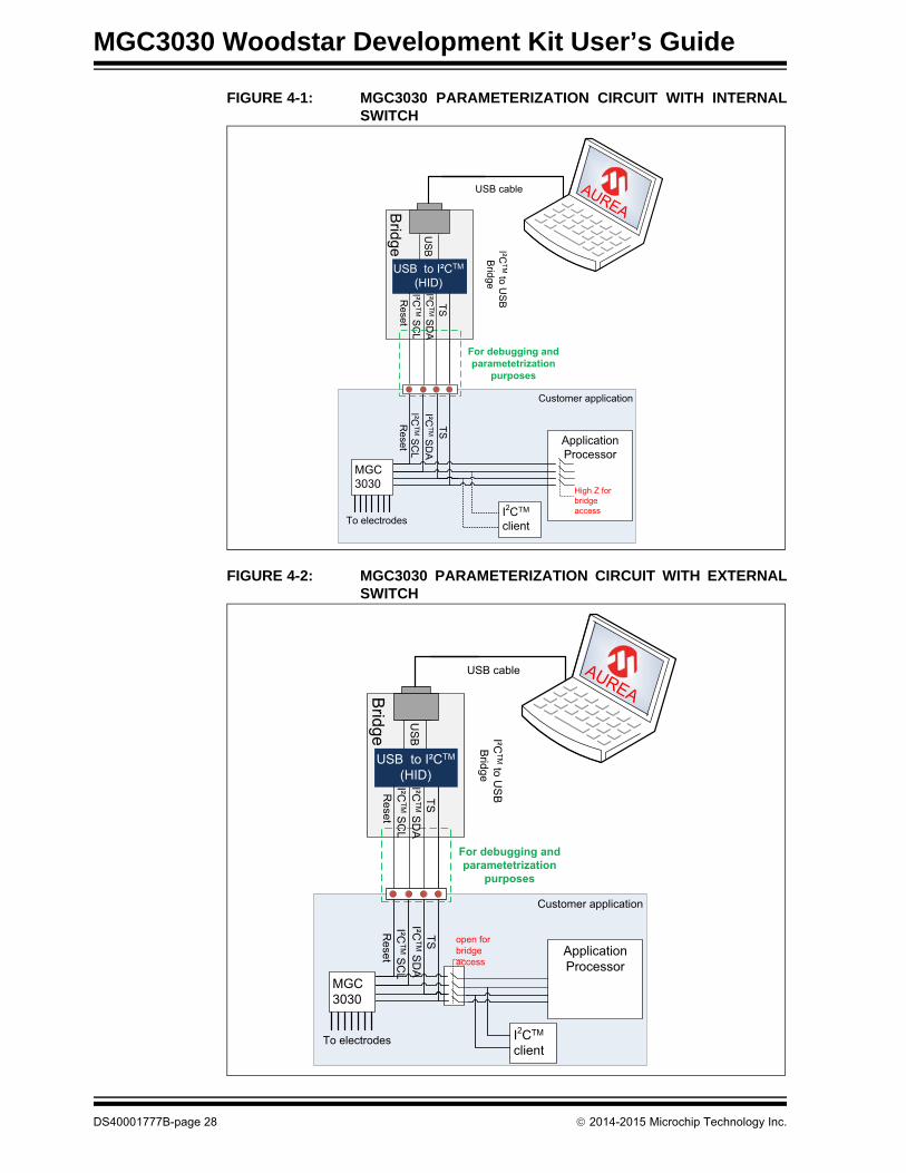
Figure 4-1 and Figure 4-2 show the control via I2C and an external PC. The WoodstarI2C to USB bridge acts as an I2C master. The application processor I2C should be:
• Switched OFF – I2C lines configured as high Z (refer to Figure 4-1)
• Switched to Slave or Listen mode• Disconnected through an external switch (refer to Figure 4-2)
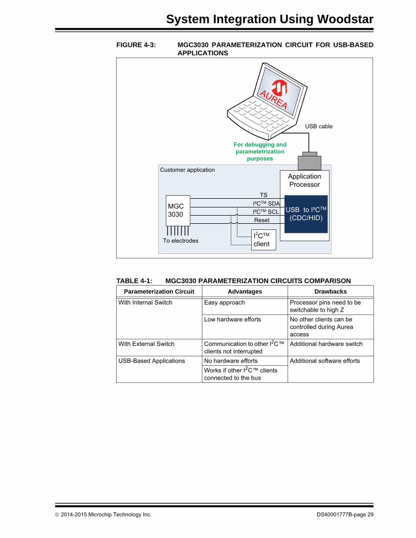
As an alternative, it is also possible to establish a USB connection between theapplication processor and a PC without using an I2C to USB bridge. Please refer toFigure 4-3.
2014-2015 Microchip Technology Inc. DS40001777B-page 27
MGC3030 Woodstar Development Kit User’s Guide
FIGURE 4-1: MGC3030 PARAMETERIZATION CIRCUIT WITH INTERNALSWITCH
FIGURE 4-2: MGC3030 PARAMETERIZATION CIRCUIT WITH EXTERNALSWITCH
Customer application
Bridge
TS
USB to I²C(HID)
I²C S
CL
I²C to U
SB
B
ridge
Application Processor
US
B
Reset
For debugging and parametetrization
purposes
USB cable
To electrodes
I²C S
DA
TSI²C
SD
AI²C
SC
LR
eset
MGC3030
High Z for bridge accessI2C
client
AUREA
Customer application
Bridge
TS
USB to I²C(HID)
I²C S
CL
I²C to U
SB
B
ridge
Application Processor
US
B
Reset
For debugging and parametetrization
purposes
USB cable
To electrodes
I²C S
DA
TSI²C
SD
AI²C
SC
LR
eset
MGC3030
I2Cclient
AUREA
open for bridge access
DS40001777B-page 28 2014-2015 Microchip Technology Inc.
System Integration Using Woodstar
FIGURE 4-3: MGC3030 PARAMETERIZATION CIRCUIT FOR USB-BASEDAPPLICATIONS
TABLE 4-1: MGC3030 PARAMETERIZATION CIRCUITS COMPARISON
Parameterization Circuit Advantages Drawbacks
With Internal Switch Easy approach Processor pins need to be switchable to high Z
Low hardware efforts No other clients can be controlled during Aurea access
With External Switch Communication to other I2C™ clients not interrupted
Additional hardware switch
USB-Based Applications No hardware efforts Additional software efforts
Works if other I2C™ clients connected to the bus
Customer applicationApplication Processor
For debugging and parametetrization
purposes
USB cable
To electrodes
TSI²C SDAI²C SCLReset
MGC3030
I2Cclient
AUREA
USB to I²C(CDC/HID)
2014-2015 Microchip Technology Inc. DS40001777B-page 29
MGC3030 Woodstar Development Kit User’s Guide
NOTES:
DS40001777B-page 30 2014-2015 Microchip Technology Inc.

MGC3030 WOODSTAR DEVELOPMENT
KIT USER’S GUIDEChapter 5. Troubleshooting
5.1 POWER LED DOES NOT ILLUMINATE
If the power LED does not illuminate, it is likely that the board is not powered.
Possible solutions:
• Check the board is connected to your PC’s USB port. • Change the USB cable or use a different USB port on your PC.
• Check if the PC is switched on.
5.2 LED 1 BLINKS FAST
When LED 1 blinks fast (~10 Hz), the USB connection is not established towards thePC.
Possible solutions:
• Make sure the Windows CDC driver is installed (refer to Appendix C. “DriverInstallation Manual”).
• Make sure the MGC3030 unit and the I2C to USB bridge are already connectedbefore plugging in the USB connection (refer to Section 2.2 “Step 1:Development Kit Assembly”).
• Reconnect the board by unplugging the USB connection and plugging it in again.
5.3 SIGNAL STREAMING STOPS
Signal stream in Aurea GUI stops when there is no approach towards the sensing area.This behavior is intended. When using the Aurea GUI, the Wake-up on Approachfeature is automatically enabled.
Possible solutions:
Disable the Wake-up on Approach feature in the Real-Time Control bar of Aurea byunchecking the Approach Detection/Power Saving check box for continuous signalstreaming.
5.4 ELECTRODE SIGNALS ARE ZERO
Signal matching parameters have been mismatched and accidentally stored into theFlash.
Possible solutions:
• Perform “Autoparameterization” in the AFE Parameterization of the Aurea Setuptab. Make sure there is no hand approach towards the electrodes during theautoparamterization process.
• Restore the default Signal Matching parameters by re-flashing the originalMGC3030 GestIC Library file.
2014-2015 Microchip Technology Inc. DS40001777B-page 31
MGC3030 Woodstar Development Kit User’s Guide
5.5 LED 1 AND 2 ON I2C TO USB BRIDGE ARE OFF
When LED 1 and LED 2 on the I2C to USB bridge are OFF but the power LED is ON,the PIC18F14K50 is in Bootloader Update mode and therefore not operating code. ThePIC18F14K50 will start in Bootloader Update mode in case the MGC3030 unit is notconnected to the I2C to USB bridge.
Possible solutions:
• Please disconnect the I2C to USB bridge from the USB. Connect the MGC3030unit and the I2C to USB bridge first and then plug in the USB connection.
DS40001777B-page 32 2014-2015 Microchip Technology Inc.
MGC3030 WOODSTAR DEVELOPMENT
KIT USER’S GUIDEAppendix A. Schematics
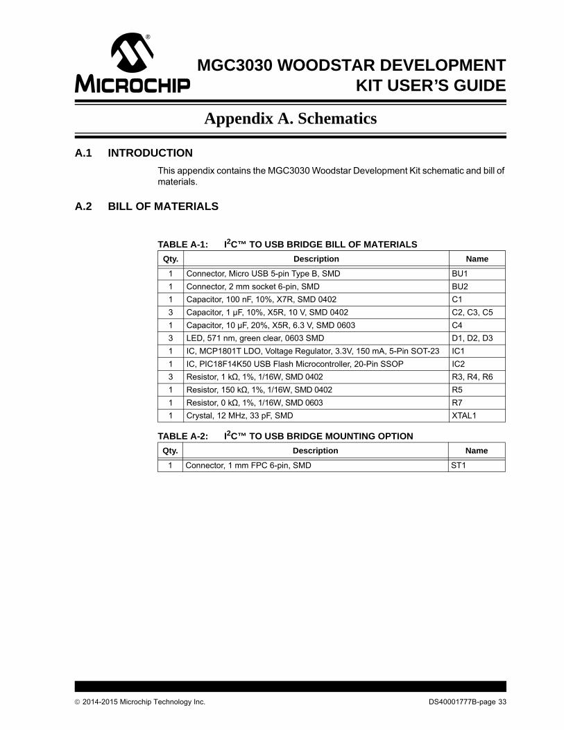
A.1 INTRODUCTION
This appendix contains the MGC3030 Woodstar Development Kit schematic and bill of materials.
A.2 BILL OF MATERIALS
TABLE A-1: I2C™ TO USB BRIDGE BILL OF MATERIALS
Qty. Description Name
1 Connector, Micro USB 5-pin Type B, SMD BU1
1 Connector, 2 mm socket 6-pin, SMD BU2
1 Capacitor, 100 nF, 10%, X7R, SMD 0402 C1
3 Capacitor, 1 µF, 10%, X5R, 10 V, SMD 0402 C2, C3, C5
1 Capacitor, 10 µF, 20%, X5R, 6.3 V, SMD 0603 C4
3 LED, 571 nm, green clear, 0603 SMD D1, D2, D3
1 IC, MCP1801T LDO, Voltage Regulator, 3.3V, 150 mA, 5-Pin SOT-23 IC1
1 IC, PIC18F14K50 USB Flash Microcontroller, 20-Pin SSOP IC2
3 Resistor, 1 kΩ, 1%, 1/16W, SMD 0402 R3, R4, R6
1 Resistor, 150 kΩ, 1%, 1/16W, SMD 0402 R5
1 Resistor, 0 kΩ, 1%, 1/16W, SMD 0603 R7
1 Crystal, 12 MHz, 33 pF, SMD XTAL1
TABLE A-2: I2C™ TO USB BRIDGE MOUNTING OPTION
Qty. Description Name
1 Connector, 1 mm FPC 6-pin, SMD ST1
2014-2015 Microchip Technology Inc. DS40001777B-page 33

MGC3030 Woodstar Development Kit User’s Guide
TABLE A-3: MGC3030 UNIT BILL OF MATERIALS
Qty. Description Name
1 Connector, 2mm socket 7pin, SMD BU1
1 Connector, 2mm header 6pin, SMD ST1
1 Capacitor, 100nF, 10%, X7R, SMD 0402 C1
2 Capacitor, 4.7µF, 20%, X5R, 6.3V, SMD 0402 C2, C3
1 LED, 571nm green clear, 0603 SMD D1
1 IC, MGC3030 3D Gesture Controller, 28 Pin SSOP IC1
2 Resistor, 1.8kΩ, 1%, 1/16W, SMD 0402 R1, R2
3 Resistor, 10kΩ, 1%, 1/16W, SMD 0603 R4, R6, R7
6 Resistor, 10kΩ, 1%, 1/16W, SMD 0402 R9, R11, R12, R13, R14, R15
1 Resistor, 1kΩ, 1%, 1/16W, SMD 0402 R10
TABLE A-4: MGC3030 UNIT MOUNTING OPTION
Qty. Description Name
1 Connector, 1 mm FPC 6-pin, SMD ST3
TABLE A-5: REFERENCE ELECTRODE BILL OF MATERIALS
Qty. Description Name
1 Connector, 1 mm FPC 6-pin, SMD ST2
DS40001777B-page 34 2014-2015 Microchip Technology Inc.
Sch
ematics
2
01
4-2
01
5 M
icroch
ip T
ech
no
log
y Inc.
D
S4
00
01
77
7B
-pa
ge
35
A.
FIG
3 BOARD SCHEMATICS AND LAYOUT
URE A-1: MGC3030 UNIT SCHEMATIC
TM
MGC3030 Woodstar Development Kit User’s Guide
FIGURE A-2: ASSEMBLY OF MGC3030 UNIT
Top View
Bottom View
TM
TM
DS40001777B-page 36 2014-2015 Microchip Technology Inc.

Sch
ematics
2
01
4-2
01
5 M
icroch
ip T
ech
no
log
y Inc.
D
S4
00
01
77
7B
-pa
ge
37
FIG
TM
TM
URE A-3: I2C™ TO USB BRIDGE SCHEMATIC

MGC3030 Woodstar Development Kit User’s Guide
FIGURE A-4: ASSEMBLY OF I2C™ TO USB BRIDGE
Top View
Bottom View
N/C
CLK
DA
T
GN
DV
DD
VP
P
ICSPTM Interface
Mic
ro U
SB
In
terf
ace
TM
TM
TM
DS40001777B-page 38 2014-2015 Microchip Technology Inc.

MGC3030 WOODSTAR DEVELOPMENT
KIT USER’S GUIDEAppendix B. Sensitivity Profile and Capacitances
B.1 INTRODUCTION
This appendix contains the sensitivity profile and the electrode capacitances of theWoodstar Development Kit hardware.
The measurement procedure of both the sensitivity profile and the electrodecapacitances are outlined in “GestIC® Design Guide” (DS40001716).
B.2 SENSITIVITY PROFILES
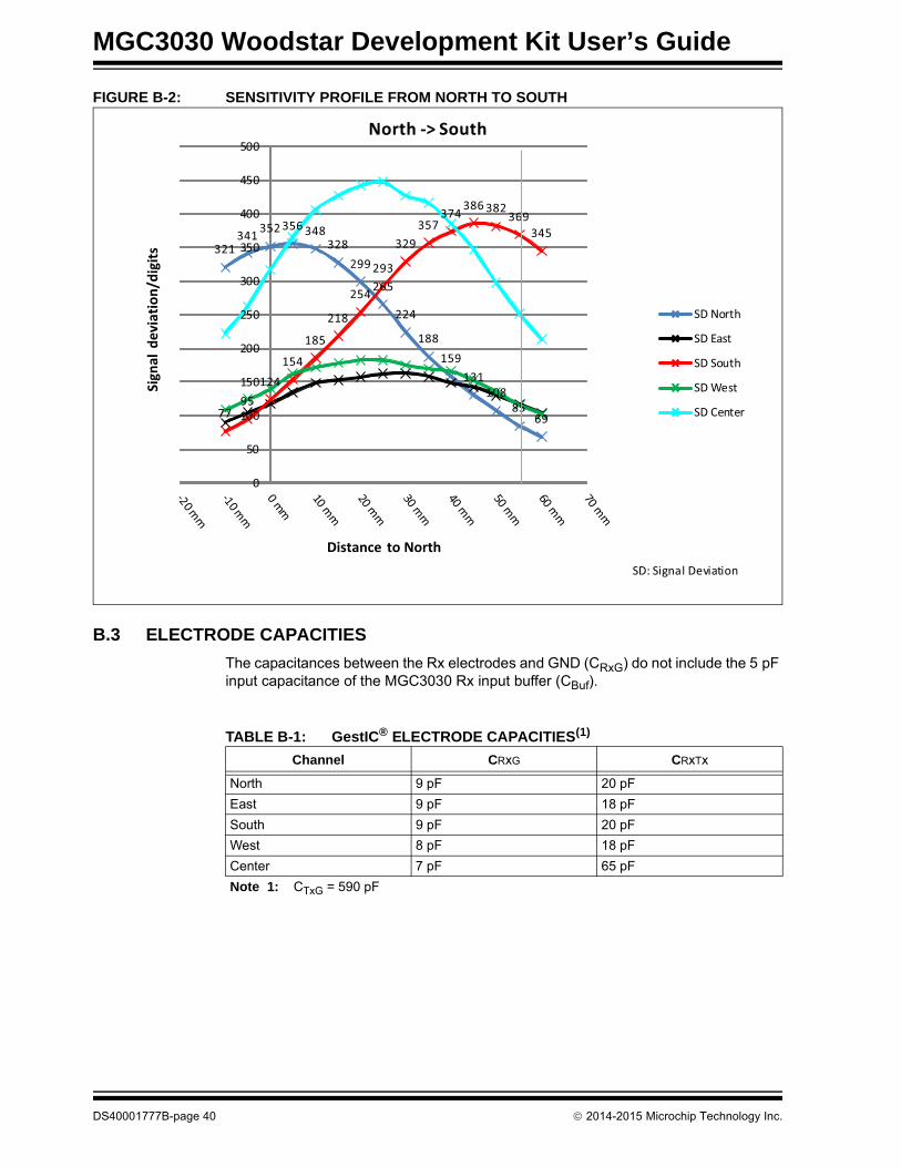
The sensitivity profiles were conducted using a 40x40x70 mm artificial hand at aconstant height of 30 mm above the electrode’s surface.
FIGURE B-1: SENSITIVITY PROFILE FROM WEST TO EAST
27 34 4564
80107
136
179
222
269
314340 340
322
275
230
287316 322
307
269
218
177
136111
8463
45 39 27
0
50
100
150
200
250
300
350
400
450
500
igna
l dev
iatio
n/di
gits
istance to West
West -> East
SD North
SD East
SD South
SD West
SD Center
SD: Signal Deviation
2014-2015 Microchip Technology Inc. DS40001777B-page 39
MGC3030 Woodstar Development Kit User’s Guide
FIGURE B-2: SENSITIVITY PROFILE FROM NORTH TO SOUTH
B.3 ELECTRODE CAPACITIES
The capacitances between the Rx electrodes and GND (CRxG) do not include the 5 pF input capacitance of the MGC3030 Rx input buffer (CBuf).
321341 352 356 348
328299
265
224
188159
131108
856977
95124
154
185
218
254
293
329357
374 386 382369
345
0
50
100
150
200
250
300
350
400
450
500ig
nal d
evia
tion/
digi
ts
istance to North
North -> South
SD North
SD East
SD South
SD West
SD Center
SD: Signal Deviation
TABLE B-1: GestIC® ELECTRODE CAPACITIES(1)
Channel CRxG CRxTx
North 9 pF 20 pF
East 9 pF 18 pF
South 9 pF 20 pF
West 8 pF 18 pF
Center 7 pF 65 pF
Note 1: CTxG = 590 pF
DS40001777B-page 40 2014-2015 Microchip Technology Inc.
MGC3030 WOODSTAR DEVELOPMENT
KIT USER’S GUIDEAppendix C. Driver Installation Manual
This section lists the steps to be taken in order to manually install the Windows CDC Driver on the PC.
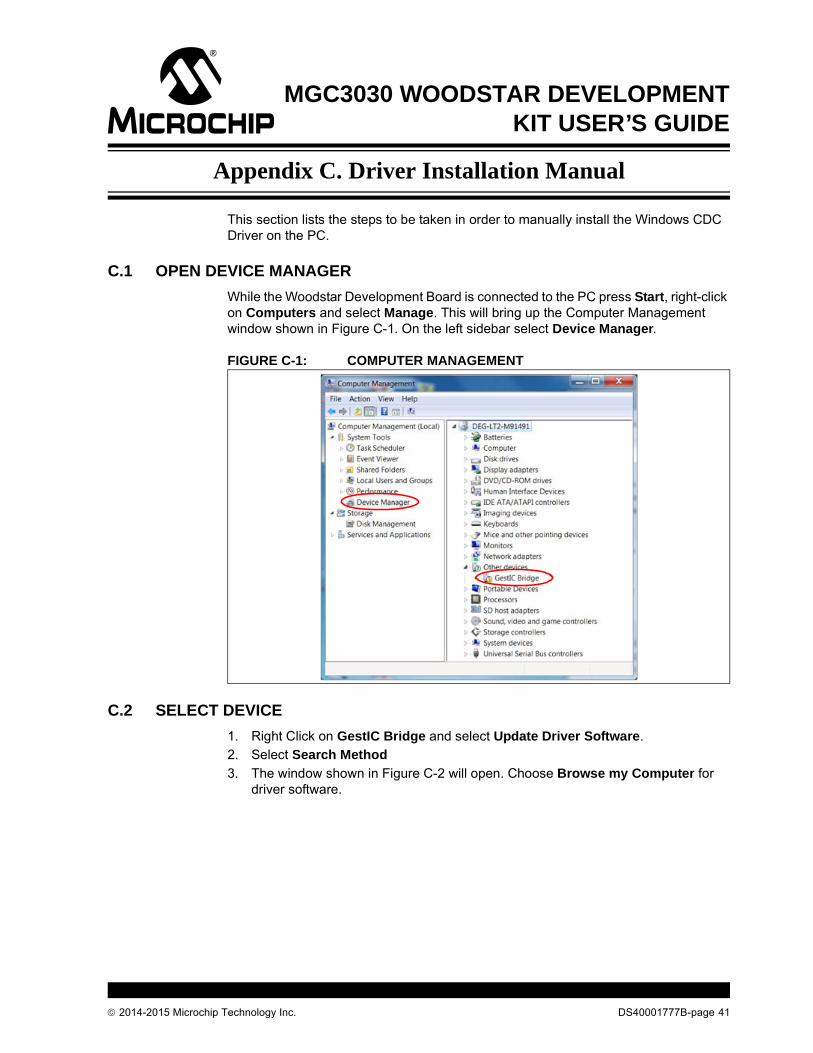
C.1 OPEN DEVICE MANAGER
While the Woodstar Development Board is connected to the PC press Start, right-click on Computers and select Manage. This will bring up the Computer Management window shown in Figure C-1. On the left sidebar select Device Manager.
FIGURE C-1: COMPUTER MANAGEMENT
C.2 SELECT DEVICE
1. Right Click on GestIC Bridge and select Update Driver Software. 2. Select Search Method
3. The window shown in Figure C-2 will open. Choose Browse my Computer for driver software.
2014-2015 Microchip Technology Inc. DS40001777B-page 41
MGC3030 Woodstar Development Kit User’s Guide
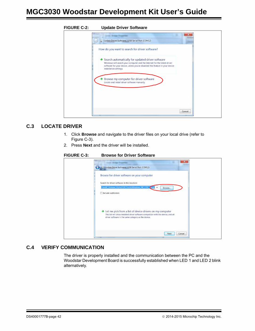
FIGURE C-2: Update Driver Software
C.3 LOCATE DRIVER
1. Click Browse and navigate to the driver files on your local drive (refer to Figure C-3).
2. Press Next and the driver will be installed.
FIGURE C-3: Browse for Driver Software
C.4 VERIFY COMMUNICATION
The driver is properly installed and the communication between the PC and the Woodstar Development Board is successfully established when LED 1 and LED 2 blink alternatively.
DS40001777B-page 42 2014-2015 Microchip Technology Inc.

MGC3030 WOODSTAR DEVELOPMENT
KIT USER’S GUIDEAppendix D. Glossary
TABLE D-1: GLOSSARYTerm Definition
AFE Analog Front End
Application Host PC or embedded controller which controls the MGC3030
Aurea MGC3030/3130 PC control software with graphical user interface
Colibri Suite Embedded DSP suite within the GestIC® Library
Deep Sleep MGC3030/3130 Power-Saving mode
E-field Electrical field
Frame Electrodes Rectangular set of four electrodes for E-field sensing
GestIC® Technology Microchip’s patented technology providing 3D free-space gesture recognition utilizing the principles of electrical near-field sensing
GestIC® Library Includes the implementation of MGC3030/3130 features and is delivered as a binary file preprogrammed on the MGC3030
Gesture Recognition Microchip’s stochastic HMM classifier to automatically detect and classify hand movement patterns
Gesture Set A set of provided hand movement patterns
HMM Hidden Markov Model
MGC3130 Single-Zone 3D Gesture and Motion Tracking Controller
MGC3030 Single-Zone 3D Gesture Sensing Controller
Position Tracking GestIC® technology feature
Self Wake-up MGC3030/3130 Power-Saving mode
Sensing Area Area enclosed by the four frame electrodes
Sensing Space Space above sensing area
Signal Deviation Term for the delta of the sensor signal on approach of the hand versus non-approach
SPU Signal Processing Unit
Approach Detection GestIC® technology feature: Power-Saving mode of the MGC3030/3130 with approach detection
2014-2015 Microchip Technology Inc. DS40001777B-page 43

MGC3030 Woodstar Development Kit User’s Guide
NOTES:
DS40001777B-page 44 2014-2015 Microchip Technology Inc.
2014-2015 Microchip Technology Inc. DS40001777B-page 45
AMERICASCorporate Office2355 West Chandler Blvd.Chandler, AZ 85224-6199Tel: 480-792-7200 Fax: 480-792-7277Technical Support: http://www.microchip.com/supportWeb Address: www.microchip.com
AtlantaDuluth, GA Tel: 678-957-9614 Fax: 678-957-1455
Austin, TXTel: 512-257-3370
BostonWestborough, MA Tel: 774-760-0087 Fax: 774-760-0088
ChicagoItasca, IL Tel: 630-285-0071 Fax: 630-285-0075
ClevelandIndependence, OH Tel: 216-447-0464 Fax: 216-447-0643
DallasAddison, TX Tel: 972-818-7423 Fax: 972-818-2924
DetroitNovi, MI Tel: 248-848-4000
Houston, TX Tel: 281-894-5983
IndianapolisNoblesville, IN Tel: 317-773-8323Fax: 317-773-5453
Los AngelesMission Viejo, CA Tel: 949-462-9523 Fax: 949-462-9608
New York, NY Tel: 631-435-6000
San Jose, CA Tel: 408-735-9110
Canada - TorontoTel: 905-673-0699 Fax: 905-673-6509
ASIA/PACIFICAsia Pacific OfficeSuites 3707-14, 37th FloorTower 6, The GatewayHarbour City, KowloonHong KongTel: 852-2943-5100Fax: 852-2401-3431
Australia - SydneyTel: 61-2-9868-6733Fax: 61-2-9868-6755
China - BeijingTel: 86-10-8569-7000 Fax: 86-10-8528-2104
China - ChengduTel: 86-28-8665-5511Fax: 86-28-8665-7889
China - ChongqingTel: 86-23-8980-9588Fax: 86-23-8980-9500
China - HangzhouTel: 86-571-8792-8115 Fax: 86-571-8792-8116
China - Hong Kong SARTel: 852-2943-5100 Fax: 852-2401-3431
China - NanjingTel: 86-25-8473-2460Fax: 86-25-8473-2470
China - QingdaoTel: 86-532-8502-7355Fax: 86-532-8502-7205
China - ShanghaiTel: 86-21-5407-5533 Fax: 86-21-5407-5066
China - ShenyangTel: 86-24-2334-2829Fax: 86-24-2334-2393
China - ShenzhenTel: 86-755-8864-2200 Fax: 86-755-8203-1760
China - WuhanTel: 86-27-5980-5300Fax: 86-27-5980-5118
China - XianTel: 86-29-8833-7252Fax: 86-29-8833-7256
China - XiamenTel: 86-592-2388138 Fax: 86-592-2388130
China - ZhuhaiTel: 86-756-3210040 Fax: 86-756-3210049
ASIA/PACIFICIndia - BangaloreTel: 91-80-3090-4444 Fax: 91-80-3090-4123
India - New DelhiTel: 91-11-4160-8631Fax: 91-11-4160-8632
India - PuneTel: 91-20-3019-1500
Japan - OsakaTel: 81-6-6152-7160 Fax: 81-6-6152-9310
Japan - TokyoTel: 81-3-6880- 3770 Fax: 81-3-6880-3771
Korea - DaeguTel: 82-53-744-4301Fax: 82-53-744-4302
Korea - SeoulTel: 82-2-554-7200Fax: 82-2-558-5932 or 82-2-558-5934
Malaysia - Kuala LumpurTel: 60-3-6201-9857Fax: 60-3-6201-9859
Malaysia - PenangTel: 60-4-227-8870Fax: 60-4-227-4068
Philippines - ManilaTel: 63-2-634-9065Fax: 63-2-634-9069
SingaporeTel: 65-6334-8870Fax: 65-6334-8850
Taiwan - Hsin ChuTel: 886-3-5778-366Fax: 886-3-5770-955
Taiwan - KaohsiungTel: 886-7-213-7830
Taiwan - TaipeiTel: 886-2-2508-8600 Fax: 886-2-2508-0102
Thailand - BangkokTel: 66-2-694-1351Fax: 66-2-694-1350
EUROPEAustria - WelsTel: 43-7242-2244-39Fax: 43-7242-2244-393Denmark - CopenhagenTel: 45-4450-2828 Fax: 45-4485-2829
France - ParisTel: 33-1-69-53-63-20 Fax: 33-1-69-30-90-79
Germany - DusseldorfTel: 49-2129-3766400
Germany - MunichTel: 49-89-627-144-0 Fax: 49-89-627-144-44
Germany - PforzheimTel: 49-7231-424750
Italy - Milan Tel: 39-0331-742611 Fax: 39-0331-466781
Italy - VeniceTel: 39-049-7625286
Netherlands - DrunenTel: 31-416-690399 Fax: 31-416-690340
Poland - WarsawTel: 48-22-3325737
Spain - MadridTel: 34-91-708-08-90Fax: 34-91-708-08-91
Sweden - StockholmTel: 46-8-5090-4654
UK - WokinghamTel: 44-118-921-5800Fax: 44-118-921-5820
Worldwide Sales and Service
03/25/14