mgf manhole boxes · normally selected for installing precast concrete manholes, ... lifting and...
TRANSCRIPT

MA
NH
OLE
BO
XE
SM
GF
TE
CH
NIC
AL
FIL
E
2.2.1Issue 2
Description
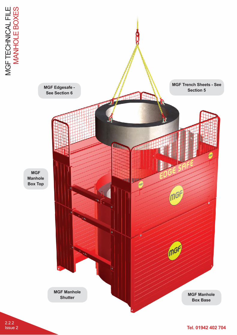
Simple to assemble, robust, four sided mechanical excavation support system designed to be installed by an excavator utilising the dig and push or excavate and lower in place techniques.
Normally selected for installing precast concrete manholes, small chambers or tanks where ground movement
5.81m and structures of max. plan dimension / diameter 4.0m.
Fabricated from fully welded Grade S355 120x60mm or 200x100mm steel box sections to form 60mm or 100mm thick panels, the system comprises manhole box bases to which up to 2 No. manhole box tops may be added to achieve additional depth. The panels are propped off each other by robust telescopic struts available in a variety of lengths to suit the required width. Panel gaps are provided on two faces to accommodate trench runs into the manhole box. All components in the system are connected together via simple pin and clip assemblies. The system is designed to be used in conjunction with MGF Trench Boxes.
MGF can supply the systems with a full range of suitable lifting and extraction chains, Edgesafe edge protection panels, Laddersafe access platforms and pole ladders, Davitsafe retrieval / fall arrest systems, Endsafe protection
Manufactured and designed in accordance with BS EN 13331 : 2002 Parts 1 and 2 Trench Lining Systems and BS 5975 (2008) Code of Practice for Temporary Works Procedures and the Permissible Stress Design of Falsework.
Product Notes
1. guidelines.
2. In a standard square plan format the boxes can have their returns closed using sheet piles bearing directly onto the telescopic cross struts. If the box is extended beyond its standard square format the telescopic struts should not be laterally loaded.
3. groundwater is present.
4. Boxes are not normally suitable for usage where ground movement is an issue and are therefore not recommended for use in live carriageway situations or adjacent existing buildings / structures.
5. Flying of the box above the base of the excavation is strictly prohibited.
6. Box systems are extremely heavy and great care must be taken in selecting a suitable excavator for handling, installing and extracting these systems. If stacking panels on site, timber packers must be used to separate the panels.
7. Boxes should not be left in-situ for extended periods within cohesive or very weak soils as earth pressures / adhesion on the panel surfaces may increase
forces to release the panels. 8.
chains to release an in-situ box from the ground prior to any attempt to lift the box out of the trench. Always use
lifting and handling the boxes or components. NB If a box becomes stuck extraction forces of up to 500kN (50Te) can be required to release each corner.
9. Prior to every lifting operation all lifting points must be carefully inspected by a competent person for evidence of damage.
10. Always enter box via a ladder located within the box and never, from an unsupported edge.
11. During lifting or extraction operations ensure personnel are well clear of the equipment.
Tel. 01942 402 704
MG
F T
EC
HN
ICA
L F
ILE
MA
NH
OLE
BO
XE
S
2.2.2Issue 2
MGF Trench Sheets - See
Section 5MGF Edgesafe -
See Section 6
MGF Manhole
Box Base
MGF Manhole
Shutter
MGF
Manhole
Box Top
MA
NH
OLE
BO
XE
SM
GF
TE
CH
NIC
AL
FIL
E
2.2.3Issue 2
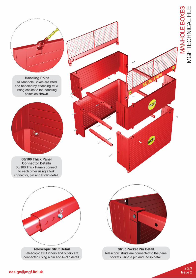
Strut Pocket Pin DetailTelescopic struts are connected to the panel
pockets using a pin and R-clip detail.
Telescopic Strut DetailTelescopic strut inners and outers are
connected using a pin and R-clip detail.
60/100 Thick Panel Connector Details
60/100 Thick Panels connect
to each other using a fork
connector, pin and R-clip detail.
Handling PointAll Manhole Boxes are lifted
and handled by attaching MGF
lifting chains to the handling
points as shown.

Tel. 01942 402 704
MG
F T
EC
HN
ICA
L F
ILE
MA
NH
OLE
BO
XE
S
2.2.4Issue 2
Product ID 4.203 4.201 4.202 4.210 4.220 4.230 4.240 4.250 4.260 4.270 4.280
Description
L × H
2000
x
1780
LW
Base
2000
x
1780
Base
2000
x
1100
Top
2500
x
2020
Base
2500
x
1100
Top
3000
x
2020
Base
3000
x
1100
Top
3500
x
2562
Base
3500
x
1624
Top
4400
x
2562
Base
4400
x
1624
Top
Alternative
Name
Lig
htw
eig
ht
Mic
ro B
ase
Mic
ro B
ase
Mic
ro T
op
Min
i B
ase
Min
i To
p
Mid
i B
ase
Mid
i To
p
Sta
nd
ard
Base
Sta
nd
ard
To
p
Tit
an
Base
Tit
an
To
p
Max
Depth**
(m)
3.98 3.98 N/A 4.22 N/A 4.22 N/A 5.81 N/A 5.81 N/A
Panel
Resistance
SWL
(kN/m2)
45 45 45 45 45 45 45 45 45 45 45
Panel
Thick/
Weight
T(mm)/(kg)
60/
380
60/
488
60/
341
60/
684
60/
414
60/
767
60/
459
100/
1340
100/
939
100/
1797
100/
1222
Approx
Assembled
Weight
(kg)
908 1122 714 1540 938 1692 1018 2762 1996 3824 2964
Internal
Trench
Width*
Wi(mm)
1880 1880 1880 2380 2380 2880 2880 3300 3300 4130 4130
Trench
Width*
We(mm)
2000 2000 2000 2500 2500 3000 3000 3500 3500 4330 4330
Clearance
Below
Bottom
Struts
C(mm)
810 810 N/A 923 N/A 923 N/A 1316 N/A 1300 N/A
Clearance
Between
Struts
Li(mm)
1751 1751 1751 2251 2251 2751 2751 3251 3251 4151 4151
Panel
Return PR
(mm)
550 550 550 670 670 670 670 912 912 1312 1312
* Greater widths (up to 5m) possible utilising Telescopic Struts provided
struts are not laterally loaded by return sheets/panels
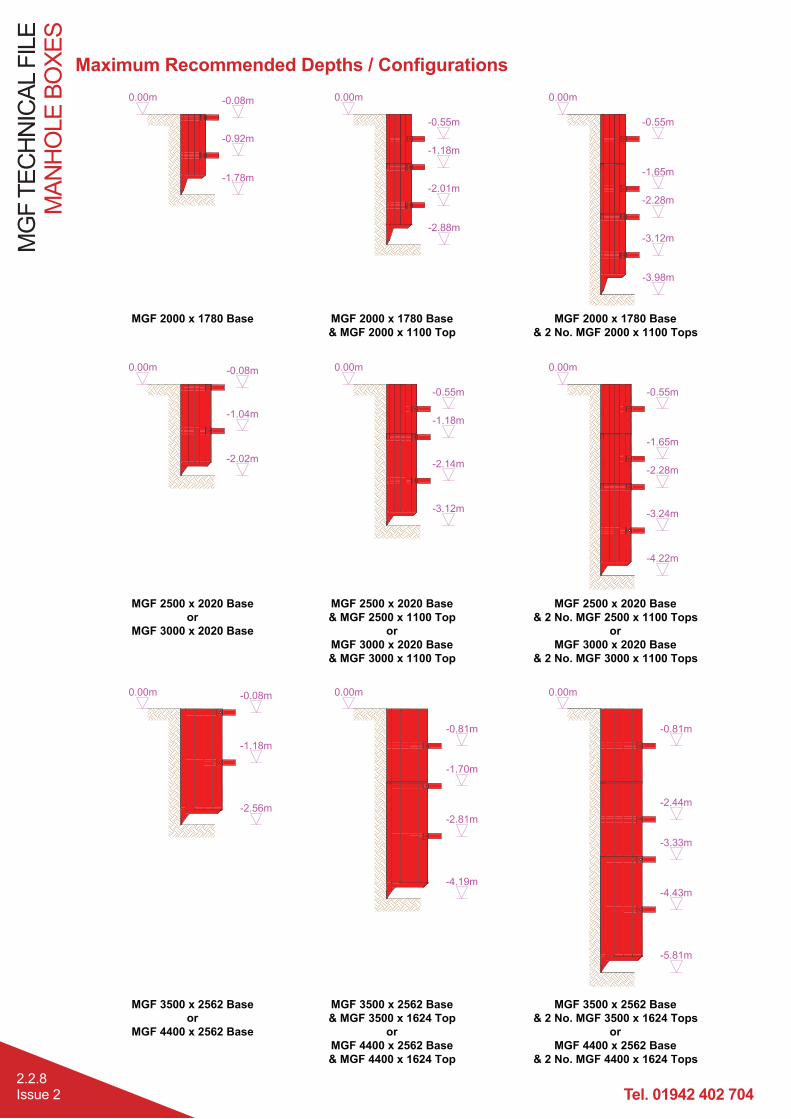
** Max depths achievable using a base and 2 tops
All Manhole Boxes utilise MGF 100 Telescopic Struts


Tel. 01942 402 704
MG
F T
EC
HN
ICA
L F
ILE
MA
NH
OLE
BO
XE
S
2.2.6Issue 2
100 Telescopic Struts
Telescopic Strut Pins and Retaining Clips
Component100 Telescopic Struts
Strut Inner Strut Outer
100x100x10 SHS 120x120x8 SHS
Material Grade S355 S355
Axial SWL 160kN 160kN
Moment SWL 20kNm 20kNm
Hole Details
Unit Mass 27.4kg/m 26.4kg/m
Component 100 Strut Pin
Ø28mm round bar, 160mm long
Material Grade 080M40 (EN8)
Shear SWL 228kN
Weight 1kg
MA
NH
OLE
BO
XE
SM
GF
TE
CH
NIC
AL
FIL
E
2.2.7Issue 2
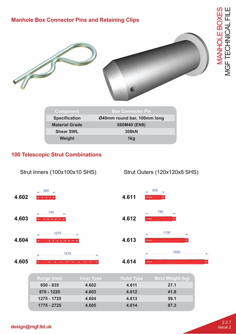
Manhole Box Connector Pins and Retaining Clips
Component Box Connector Pin
Ø40mm round bar, 100mm long
Material Grade 080M40 (EN8)
Shear SWL 308kN
Weight 1kg
100 Telescopic Strut Combinations
Range (mm) Inner Type Outer Type Strut Weight (kg)
650 - 835 4.602 4.611 27.1
870 - 1220 4.603 4.612 41.8
1275 - 1725 4.604 4.613 59.1
1775 - 2725 4.605 4.614 87.3
Tel. 01942 402 704
MG
F T
EC
HN
ICA
L F
ILE
MA
NH
OLE
BO
XE
S
2.2.8Issue 2
MA
NH
OLE
BO
XE
SM
GF
TE
CH
NIC
AL
FIL
E
2.2.9Issue 2
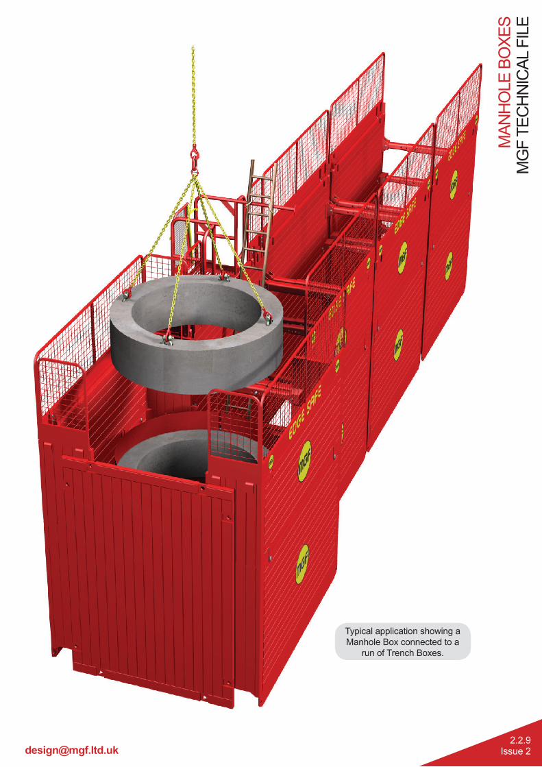
Typical application showing a
Manhole Box connected to a
run of Trench Boxes.