micro capillary pumped loop for electronic cooling
TRANSCRIPT
13
Micro Capillary Pumped Loop for Electronic Cooling
Seok-Hwan Moon and Gunn Hwang Electronics and Telecommunications Research Institute (ETRI)
Korea
1. Introduction
Electronic devices have been minimized, but their performance is becoming better and better. Their heat flux has been significantly increased and has already exceeded about 100 W/cm2 recently. The insufficient dissipating of the heat flux may lead to performance decrease or failure of the electronic device and components. Heat flux in laptop computers has not been questioned; therefore, only a heat sink has been applied on cooling them. Recently, however, a more powerful cooling solution is sought for high heat flux. Solid materials with high thermal conductivity have been mainly used in low heat flux applications, whereas small-sized heat pipes have been utilized in high heat flux applications. The use of small-sized heat pipes in electronic devices like laptop computers has only been developed recently. For example, the use of heat pipes with diameter of 3–4 became common in laptop and desktop computers only during the early 2000s. Recently, as electronic devices have started to become smaller and thinner, heat pipes with diameter of 3–4 mm have been pressed to fit the form factor to them. However, a lot of problems were encountered in their thermal performance, thus micro heat pipes (MHPs) were developed to solve them. Specifically, a flat plate micro heat pipe (FPMHP) with diameter of less than 1.5 mm was developed by Moon (Moon et al., 2002). FPMHPs are being used mainly in display panel BLU applications and are being prepared to be used in the LED headlight of vehicles. However, in spite of their thermal performance and broad applications, FPMHPs may still show degradation in thermal performance in the case of thinner applications. If we consider phase-change cooling devices like heat pipes that have thermal conductivity that is 500 times larger than copper rods for small-sized and thin electronic devices, there is a need to develop new cooling methods suitable for them. A thin flat plate type micro capillary pumped loop (CPL) with thickness of less than 2 mm was developed by Moon as a trial product. The proposed micro CPL has two-staged grooves in the evaporator, instead of poles, for preventing the backflow of the vapor bubbles; this is a simpler structure compared to that of a micro CPL with poles. A large vapor space from the evaporator to the condenser was also constructed in the middle plate to allow for the reduction of the flow resistance of the vapor. The micro CPL was fabricated using MEMS technology and was composed of lower, middle, and upper substrates. The lower substrate was composed of silicon, while the middle and upper substrates were made from Pyrex glass for visualization. Through a preliminary test, it was verified that there was no leakage at the adhesion interface between the lower and the middle or upper substrates
www.intechopen.com
Heat Analysis and Thermodynamic Effects 272
and at the bonding interface between the lower substrate and the fill tube. Although the experimental studies for the micro CPL have been poor to date, we obtained reasonable experimental results in this study. The performance test result showed a heat transfer rate of 8.5 W for the micro CPL, and we could observe the operating characteristics of circulating or evaporating and condensing by visualization. Pure distilled water was used as working fluid.
2. Cooling methods for small-sized electronic devices
A cooling module with 3–4 mm diameter heat pipe, combined with Al heat sink, is mainly used for desktop PCs belonging to large-sized personal devices. However, a pressed 3–4 mm diameter heat pipe is used for laptop PCs due to its limited inner space (Moon et al., 2001). A decrease in heat transfer rate may occur in the case of pressed flat heat pipe due to the reduction of the inner space for the flow path of the working fluid and the deformation of the specific wick structure for capillary pressure (Kim et al., 2001). Thus, the thickness of the heat pipe is limited for its normal performance. Studies on flat plate heat pipes or MHPs that are less than 2 mm thick have been conducted (Moon et al., 1999; Moon et al., 2002). A heat pipe of small thickness or diameter is not suitable for high heat transfer rate application, but for small-sized mobile devices as cooling solution. In the case of an MHP, it is not easy for the wick for liquid flow path to be inserted into it due to its small size. Therefore, grooves were fabricated on the MHP envelope or the sharp corners of the polygonal structure by reforming itself act as the wick. Tubular type MHPs with circular or polygonal cross section are suitable for small-sized application, whereas flat plate type MHPs are suitable for display application. Cooling solutions that may be considered for small-sized electronic and telecommunication devices are as follows. Materials with high thermal conductivity like copper and aluminum are cooling solutions that can be used easily. Such materials are widely used as cooling solutions in the fields of electronic packaging module and system levels. A liquid cooling using micro channels is suitable for high heat flux application due to its high heat transfer rate. However, because it has constraint in the form factor, it is not suitable for mobile application. Furthermore, overall, the spray cooling method and thermo-electric cooling (TEC) may be considered for a specific application.
3. Micro Heat Pipes (MHPs)
3.1 Characteristics of the MHP
Because MHPs have limited inner space compared to medium-size heat pipes, inserting additional wick for liquid flow path is not easy. Therefore, MHPs are characterized to have capillary structure on their wall. MHPs have small vaporizing amount with latent heat due to their small size, therefore they are not suitable for high heat flux application. The existence of non-condensable gas, albeit in very small amount, can lead to the decrease in performance; therefore, high-quality fabricating process is needed. Cotter (Cotter, 1984) was first to propose the concept of an MHP for the purpose of cooling electronic devices. The MHP was so small a heat pipe that the mean radius of curvature of the liquid-vapor interface is comparable to the hydraulic radius of the flow channel. Typically, MHPs have a convex but cusped cross section with hydraulic diameters of 10–500 µm and lengths of 10–50 mm (Faghri, 1995). Since the initial conceptualization by Cotter in 1984, numerous analytical and experimental investigations have been reported so far.
www.intechopen.com

Micro Capillary Pumped Loop for Electronic Cooling 273
According to the previous investigations reported by Cotter (Cotter, 1984), Babin and Peterson (Babin et al., 1990), and Gener (Gerner, 1989), the maximum heat transport capacity of the MHP with 0.01–0.5 mm hydraulic radius was 0.03–0.5 W and corresponded to 10 W/cm2 in the heat flux based on the surface area of the evaporator. Wu and Peterson (Wu et al., 1991) also reported that Qmax = 4–5 W or q"lim = 5 W/cm2 for a flat MHP with Dh = 1 mm. Thus, Faghri (Faghri, 1995) mentioned that it was necessary to improve the maximum heat transport capacity in order to cover the thermal load (> 10 W/cm2) encountered in most main ICs of current computers and to widely apply the MHP to computers as a cooling device. The maximum heat transfer rate of the MHP is increased as the operating temperature is increased, which is similar to the medium-sized heat pipe. Fig. 1 shows the maximum heat transfer rate according to the operating temperature variation for the curved rectangular MHP fabricated through this study, which has 30% of working fluid compared with the total volume. It is a characteristic of the MHP to have liquid block at the condenser during its operation due to its small inner fluid flow space. The liquid block induces a decrease in its performance since vapor cannot reach the condenser area, which is being occupied by the liquid block, and thus cannot accomplish phase-change heat transfer in there. Thus, optimum design of the working fluid amount is important to minimize the volume of the liquid block. Fig. 2 shows the capillary radius distribution over axial direction of the MHP in conditions of 50 °C of operating temperature. The capillary radius can be calculated by equation (1):
1 2
1 1c v l
c c
P P Pr r
(1)
Where rc1 and rc2 are the principal capillary radii of the meniscus. For the MHP designed in this study, the capillary radius can be considered as rc1rc(x) and rc2 since capillary radius variation over axial direction occurred, but the capillary radius variation through radial direction nearly not occurred. Fig. 3 shows the vapor and liquid pressure distributions over axial direction of the MHP in the condition of 50 °C of operating temperature.
30 40 50 60 70 80 90
0.0
0.2
0.4
0.6
0.8
1.0
1.2
1.4
Ma
xim
um
He
at
Tra
nsp
ort
Ca
pa
city (
W)
Operating Temperature(oC)
Copper
Percent of Filling : 30%
Fig. 1. Maximum heat transport capacity according to operating temperatures
www.intechopen.com

Heat Analysis and Thermodynamic Effects 274
0.000 0.005 0.010 0.015 0.020 0.025 0.030 0.035
0.0000
0.0001
0.0002
0.0003
0.0004
0.0005
0.0006
0.0007
Ca
pill
ary
ra
diu
s (
m)
Axial position x (m) Fig. 2. Capillary radius variation over axial position
0.000 0.005 0.010 0.015 0.020 0.025 0.030 0.035
0
200
400
600
800
1000
1200
1400
Vapor
Liquid
Pre
ssu
re d
iffe
ren
ce
(P
a)
Axial position x (m) Fig. 3. Pressure distributions of vapor and liquid over axial position
3.2 Fabrication of the MHP
The size of the MHP developed in this study is smaller than that of the miniature heat pipe with diameter of 3–4 mm. The MHP could be manufactured using current mechanical technology of the simple manufacturing process. Therefore, this manufacturing process of the MHP has a good productivity. In fact, the microstructures of the MHP may be manufactured with etching process (Gerner, 1989), but such process has disadvantages in terms of productivity and cost. The container of the MHP was manufactured with the drawing process, and Fig. 1 shows its cross section. This MHP does not have additional wick installed on the inner wall of the general heat pipe, but has sharp corners made with structural deformation of its wall, which serves as wick.
www.intechopen.com

Micro Capillary Pumped Loop for Electronic Cooling 275
The condensed liquid at the condenser of the MHP returns to the evaporator through the capillary force of the liquid. It is important for the MHP to have sharp edges in the corners to enable the working liquid to return from the condenser to the evaporator. The rectangular MHP with curved sides (Fig. 4a) has advantages for thermal performance, such as larger inner space for vapor flow and an additional corner for liquid path, than those of the triangular MHP (Fig. 4b). Because the edge angle at the corner of the triangular MHP is sharper than that of the rectangular MHP, the capillary force of the working fluid at the triangular MHP is larger than that at the rectangular MHP. The specification of the MHP is shown in Table 1.
(a) Curved rectangular (b) Curved triangular
Fig. 4. Cross section of MHP
Triangular MHP Curved rectangular
MHP Total length (mm) 50/100 Evaporator length 10 mm
Adiabatic section length 15 mm Condenser length 25 mm
Working fluid Pure water Fill ratio of working fluid 20%
Number of corners 3 4 Container material Oxygen-free copper
Container manufacturing method Drawing
Table 1. Experimental specification of MHP
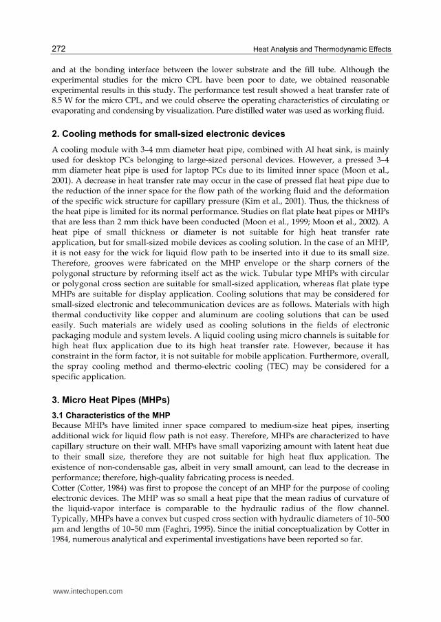
FPMHPs with cross section of rectangular, modified rectangular, and triangular types were newly developed in the present study. The container of the FPMHPs was manufactured by the extrusion process, which could effectively form a sharp edge and significantly enhance the productivity of FPMHPs. Moreover, mass production of FPMHPs is possible through this method. The FPMHPs have three types of cross section – rectangular, modified rectangular, and triangular. Fig. 5 shows the cross section of the FPMHPs; Table 2 presents the dimensions of the FPMHPs.
www.intechopen.com
Heat Analysis and Thermodynamic Effects 276
Thickness Width Total length
Rectangular type 2 mm 12 mm 50 mm
Modified rectangular type 1.5 mm 14 mm 50 mm
Triangular type 1.5 mm 12 mm 50 mm
Table 2. Dimensions of the FPMHPs
(a) Rectangular (b) Modified rectangular (c) Triangular
Fig. 5. Cross sections of the FPMHPs
3.3 Thermal performance of the MHP
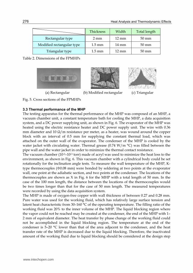
The testing apparatus for the thermal performance of the MHP was composed of an MHP, a vacuum chamber unit, a constant temperature bath for cooling the MHP, a data acquisition system, and a DC power supplying unit, as shown in Fig. 6. The evaporator of the MHP was heated using the electric resistance heater and DC power supply unit. The wire with 0.36 mm diameter and 10 Ω/m resistance per meter, as a heater, was wound around the copper block with an interval of 0.5 mm for supplying the constant thermal load, which was attached on the outer wall of the evaporator. The condenser of the MHP is cooled by the water jacket with circulating water. Thermal grease (0.74 W/m °C) was filled between the pipe wall and the water jacket in order to minimize the thermal contact resistance. The vacuum chamber (10-2–10-3 torr) made of acryl was used to minimize the heat loss to the environment, as shown in Fig. 6. This vacuum chamber with a cylindrical body could be set rotationally for the inclination angle tests. To measure the wall temperature of the MHP, K-type thermocouples (Φ0.08 mm) were bonded by soldering at two points at the evaporator wall, one point at the adiabatic section, and two points at the condenser. The locations of the thermocouples are shown as X in Fig. 6 for the MHP with a total length of 50 mm. In the case of the 100 mm length, the distance between the locations of the thermocouples would be two times longer than that for the case of 50 mm length. The measured temperatures were recorded by using the data acquisition system. The MHP is made of oxygen-free copper with wall thickness of between 0.27 and 0.28 mm. Pure water was used for the working fluid, which has relatively large surface tension and latent heat characteristic from 30–160 °C of the operating temperature. The filling ratio of the working fluid was 20% to the inner volume of the MHP. The liquid blocking region where the vapor could not be reached may be created at the condenser, the end of the MHP with 1–2 mm of equivalent diameter. The heat transfer by phase change of the working fluid could not be accomplished in the liquid blocking region. The temperature at the end of the condenser is 5–20 °C lower than that of the area adjacent to the condenser, and the heat transfer rate of the MHP is decreased due to the liquid blocking. Therefore, the inactivated amount of the working fluid due to liquid blocking should be considered at the design step
www.intechopen.com
Micro Capillary Pumped Loop for Electronic Cooling 277
of the MHP for calculating the filling ratio of the working fluid. The generation mechanism for the liquid blocking has not been reported in detail at any papers and still remained as an undeveloped field. The experimental test was performed to investigate the thermal performance of the MHP. The operating temperature of the MHP identical with the temperature at the adiabatic section of the MHP was considered for the four cases – 60 °C, 70 °C, 80 °C, and 90 °C. The temperature and the amount of coolant circulating between the water jacket and the constant temperature bath were controlled carefully to maintain the conditions of the constant operating temperature of the MHP. The thermal load supplied to the MHP was increased stepwise by 0.5 W from 0.5 W. The wall temperature of the MHP was recorded at the steady state by each thermal load step. The measurement was stopped when the wall temperature of the evaporator of the MHP rapidly increased due to dry-out. The wall temperatures of the evaporator, the adiabatic section, and the condenser of the MHP were averaged in each zone. This test was measured in the chamber with vacuum condition of 10-2–10-3 torr. The results of the present study included errors in measurement, i.e., the tolerance in the heat supply (0.05 V for voltage, 0.01 A for current) and that in the temperature measurement (0.1 °C). The performance testing apparatus of the FPMHP is similar to that of the circular type MHP.
3.3 3.3 7.57.5 8.38.3
10 15 25
Evaporator
(Heater)
Adiabatic
Section
Condenser
(Water jacket)
50
Vacuum chamber(10-2~10-3torr)
[Unit: mm]
Vacuum
pumpData logger
Personal
computer
Constant
Temp. BathPower Supply
A
V
X : Thermocouple location
3.3 8.3
Fig. 6. Experimental apparatus
A heat pipe can transport a large amount of heat with a slight temperature difference between the evaporator and the condenser. In general, one of the test procedures to check whether a non-condensable gas exists in the heat pipe or a heat pipe is operated well just after the end of the manufacturing process is to measure the temperature difference between the evaporator and the condenser. In that case, however, we should remember that each heat pipe has a temperature difference as one’s own. In the case of a small-sized heat pipe like the one in the present study, high-precision technologies are needed in the manufacturing process because the presence of non-condensable gases or contaminants, albeit small in amount, can be detrimental to the heat pipe performance.
www.intechopen.com

Heat Analysis and Thermodynamic Effects 278
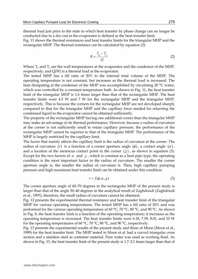
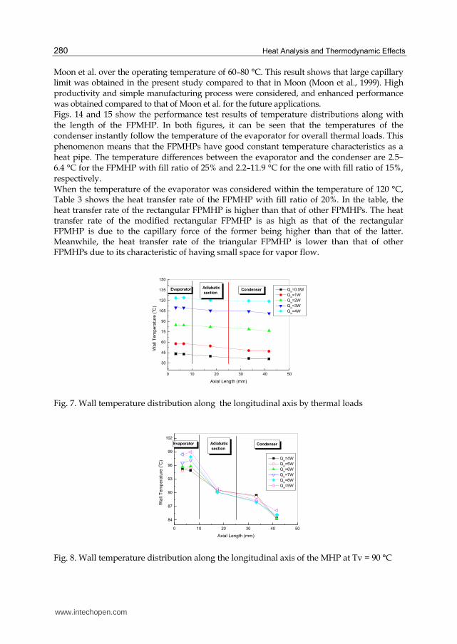
Fig. 7 shows the temperature distribution by the axial length of 50 mm. The tested MHP has a curved triangular cross section and a 20% filling ratio to the inner total volume. The heat was dissipated only at the condenser with the conduction heat transfer. The temperatures were averaged over 60 seconds after steady state to reduce minor temperature fluctuation error. As shown in Fig. 7, the wall temperatures of the MHP are increased as the thermal load is increased. This means that the thermal equilibrium, which is the isothermal property of the MHP from the evaporator to the condenser, is well accomplished. The temperature differences between the evaporator and the condenser were 4.3–9.8 °C over the thermal loads of 0.5–4 W. However, the temperature difference of 9.8 °C between the evaporator and the condenser in the thermal load of 1 W is higher than that in other thermal loads. This is because the amount of latent heat to be transported toward the condenser is small by insufficient vaporization at the evaporator, and the thermal resistance is high by a relatively thick liquid film under low thermal load near 1 W. Fig. 8 shows the temperature distribution by the axial length at the operating temperature of 90 °C, which equals the temperature at the adiabatic section. The tested MHP is the same as the one in Fig. 7. It is seen that the temperature difference between the evaporator and the condenser is increased as the thermal load is increased at the constant operating temperature of 90 °C. This can be explained by the fact that vapor flow velocity is increased as the thermal load is increased. Therefore, the friction force on the vapor-liquid interface and the pressure drop in the liquid flow are increased. Because the space for the vapor flow in the MHP is narrower than that in the conventional heat pipe, the pressure drop caused by the friction on the vapor-liquid interface may largely affect the MHP performance. Fig. 9 shows the effect of the inclination angle on the thermal performance of the triangular MHP. In the figure, the negative inclination angle indicates a top heating mode in which the evaporator is located higher than the condenser, and conversely, the positive inclination angle means a bottom heating mode in which the evaporator is located lower than the condenser. As shown in Fig. 9, the effect of the inclination angle on the thermal performance is small. The thermal performance of the MHP was almost the same for the tilting mode from the horizontal mode to the top heating mode with –90 degrees. However, there was a decrease in the thermal performance of the MHP as the inclination of the MHP was rotated from the bottom heating mode to the top heating mode. That is, the thermal performance of the triangular MHP was very stable in the bottom heating mode, and it is seen that the capillary force of the working fluid was enough to flow from the condenser to the evaporator. The triangular MHP has the limiting power of 4.51 W at the top heating mode of –90 degrees. Fig. 10 shows the overall heat transfer coefficient according to the total length of the triangular MHP. The considered lengths of the MHP were 50 mm and 100 mm. In the case of the MHP with a small-sized equivalent diameter smaller than 2 mm, the effect of the pipe length on the thermal performance of the MHP could be large. This is due to the fact that the pressure losses by friction at the vapor-liquid interface and the capillary limitation for returning the condensed liquid are significantly dominant as the pipe length is increased. As shown in Fig. 6, the thermal performance of the triangular MHP tends to be increased according to the decrease in the pipe length. In the case of the triangular MHP, the overall heat transfer coefficient was enhanced about 92% when the total length was decreased from 100 mm to 50 mm for the thermal load of 3 W. In the future, more detailed experimental results for the effect of the pipe length on the thermal performance of the MHP will be studied. A dry-out state occurs when the temperature at the evaporator’s lowest end for the bottom heating mode is abruptly increased compared to other temperatures at the evaporator. The
www.intechopen.com
Micro Capillary Pumped Loop for Electronic Cooling 279
thermal load just prior to the state in which heat transfer by phase change can no longer be conducted due to a dry-out in the evaporator is defined as the heat transfer limit. Fig. 11 shows the thermal resistances and heat transfer limits for the triangular MHP and the rectangular MHP. The thermal resistance can be calculated by equation (2):
T Te cR
Q
(2)
Where Te and Tc are the wall temperatures at the evaporator and the condenser of the MHP, respectively, and Q(W) is a thermal load at the evaporator. The tested MHP has a fill ratio of 20% to the internal total volume of the MHP. The operating temperature is not constant, but increases as the thermal load is increased. The heat dissipating at the condenser of the MHP was accomplished by circulating 20 °C water, which was controlled by a constant temperature bath. As shown in Fig. 11, the heat transfer limit of the triangular MHP is 1.6 times larger than that of the rectangular MHP. The heat transfer limits were 4.5 W and 7 W for the rectangular MHP and the triangular MHP, respectively. This is because the corners for the rectangular MHP are not developed sharply compared to that for the triangular MHP and the capillary force needed for returning the condensed liquid to the evaporator cannot be obtained sufficiently. The property of the rectangular MHP having one additional corner than the triangular MHP may make an advantage in its thermal performance. However, because a radius of curvature at the corner is not sufficiently small to retain capillary pressure, the performance of the rectangular MHP cannot be superior to that of the triangular MHP. The performance of the MHP is largely restricted by the capillary limit. The factor that mainly affects the capillary limit is the radius of curvature at the corner. The radius of curvature ( )r is a function of a corner aperture angle ( ) , a contact angle ( ) , and a location of the meniscus contact point in the corner ( ) , as shown in equation (3). Except for the two factors of and , which is constant as a heat pipe type, the operating condition is the most important factor to the radius of curvature. The smaller the corner aperture angle is, the smaller the radius of curvature is. Then, high capillary pumping pressure and high maximum heat transfer limit can be obtained under this condition.
( , , )r f (3)
The corner aperture angle of 60–70 degrees in the rectangular MHP of the present study is larger than that of the angle 30–40 degrees in the analytical result of Zaghdoudi (Zaghdoudi et al., 1997); therefore, the small radius of curvature cannot be obtained. Fig. 12 presents the experimental thermal resistance and heat transfer limit of the triangular MHP for various operating temperatures. The tested MHP has a fill ratio of 20% and was performed for the various operating temperature of 60 °C, 70 °C, 80 °C, and 90 °C. As shown in Fig. 8, the heat transfer limit is a function of the operating temperature; it increases as the operating temperature is increased. The heat transfer limits were 6.18, 7.59, 8.01, and 10 W for the operating temperatures of 60 °C, 70 °C, 80 °C, and 90 °C, respectively. Fig. 13 presents the experimental results of the present study and those of Moon (Moon et al., 1999) for the heat transfer limit. The MHP tested in Moon et al. had a curved triangular cross section and a stainless steel as container material. Pure water was used as working fluid. As shown in Fig. 13, the heat transfer limit of the present study is 1.7–2.1 times larger than that of
www.intechopen.com
Heat Analysis and Thermodynamic Effects 280
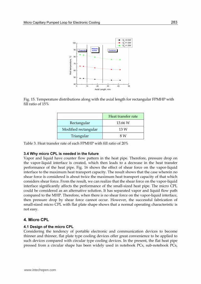
Moon et al. over the operating temperature of 60–80 °C. This result shows that large capillary limit was obtained in the present study compared to that in Moon (Moon et al., 1999). High productivity and simple manufacturing process were considered, and enhanced performance was obtained compared to that of Moon et al. for the future applications. Figs. 14 and 15 show the performance test results of temperature distributions along with the length of the FPMHP. In both figures, it can be seen that the temperatures of the condenser instantly follow the temperature of the evaporator for overall thermal loads. This phenomenon means that the FPMHPs have good constant temperature characteristics as a heat pipe. The temperature differences between the evaporator and the condenser are 2.5–6.4 °C for the FPMHP with fill ratio of 25% and 2.2–11.9 °C for the one with fill ratio of 15%, respectively. When the temperature of the evaporator was considered within the temperature of 120 °C, Table 3 shows the heat transfer rate of the FPMHP with fill ratio of 20%. In the table, the heat transfer rate of the rectangular FPMHP is higher than that of other FPMHPs. The heat transfer rate of the modified rectangular FPMHP is as high as that of the rectangular FPMHP is due to the capillary force of the former being higher than that of the latter. Meanwhile, the heat transfer rate of the triangular FPMHP is lower than that of other FPMHPs due to its characteristic of having small space for vapor flow.
0 10 20 30 40 50
30
45
60
75
90
105
120
135
150
CondenserAdiabatic
sectionEvaporator
Wa
ll T
em
pe
ratu
re (
oC
)
Axial Length (mm)
Qin=0.5W
Qin=1W
Qin=2W
Qin=3W
Qin=4W
Fig. 7. Wall temperature distribution along the longitudinal axis by thermal loads
0 10 20 30 40 50
84
87
90
93
96
99
102
CondenserAdiabatic
section
Evaporator
Wall
Tem
pe
ratu
re (
oC
)
Axial Length (mm)
Qin=4W
Qin=5W
Qin=6W
Qin=7W
Qin=8W
Qin=9W
Fig. 8. Wall temperature distribution along the longitudinal axis of the MHP at Tv = 90 °C
www.intechopen.com

Micro Capillary Pumped Loop for Electronic Cooling 281
-90 -45 0 45 900
5
10
15
20
25
He
at
Tra
nsfe
r L
imit (
W)
Inclination Angle (degree)
Curved triangular MHP
Fill ratio of 20%
Fig. 9. Thermal performance by inclination angle
0 1 2 3 4
0
200
400
600
800
1000
1200
1400
Ove
rall
He
at T
ran
sfe
r C
oe
ffic
ien
t (W
/m2oC
)
Input Power (W)
Ltotal
=100mm
Ltotal
=50mm
Fig. 10. Overall heat transfer coefficient by total length
0 1 2 3 4 5 6 7 80
5
10
15
20
25
The
rma
l R
esis
tance (
oC
/W)
Input Power (W)
Curved rectangular MHP
Curved triangular MHP
Fig. 11. Performance comparison by cross-section type
www.intechopen.com

Heat Analysis and Thermodynamic Effects 282
0 2 4 6 8 10 120
2
4
6
8
10
Dryout points
Th
erm
al R
esis
tance
(oC
/W)
Input Power (W)
Tv=60oC
Tv=70oC
Tv=80oC
Tv=90oC
Fig. 12. Thermal performance by the operating temperature
50 60 70 80 90
2
4
6
8
10
12
He
at
Tra
nsfe
r L
imit (
W)
Operating Temperature (oC)
Experimental data(Present study)
Experimental data(Moon et al,1999)
Fig. 13. Experimental results comparison between the present study and Moon et al.
0 10 20 30 40 5030
45
60
75
90
105
120
135Condenser
Adiabatic
sectionEvaporator
Wa
ll T
em
pe
ratu
re,
oC
Axial Length, mm
Qin=0.5W
Qin=1W
Qin=2W
Qin=3W
Fig. 14. Temperature distributions along FPMHP with fill ratio of 25% with the axial length for rectangular
www.intechopen.com
Micro Capillary Pumped Loop for Electronic Cooling 283
0 10 20 30 40 5040
50
60
70
80
90
100
CondenserAdiabatic
sectionEvaporator
Wa
ll te
mp
era
ture
, oC
Axial Length, mm
Qin=0.5W
Qin=1.0W
Qin=1.5W
Fig. 15. Temperature distributions along with the axial length for rectangular FPMHP with fill ratio of 15%
Heat transfer rate
Rectangular 13.66 W
Modified rectangular 13 W
Triangular 8 W
Table 3. Heat transfer rate of each FPMHP with fill ratio of 20%
3.4 Why micro CPL is needed in the future
Vapor and liquid have counter flow pattern in the heat pipe. Therefore, pressure drop on the vapor-liquid interface is created, which then leads to a decrease in the heat transfer performance of the heat pipe. Fig. 16 shows the effect of shear force on the vapor-liquid interface to the maximum heat transport capacity. The result shows that the case wherein no shear force is considered is about twice the maximum heat transport capacity of that which considers shear force. From the result, we can realize that the shear force on the vapor-liquid interface significantly affects the performance of the small-sized heat pipe. The micro CPL could be considered as an alternative solution. It has separated vapor and liquid flow path compared to the MHP. Therefore, when there is no shear force on the vapor-liquid interface, then pressure drop by shear force cannot occur. However, the successful fabrication of small-sized micro CPL with flat plate shape shows that a normal operating characteristic is not easy.
4. Micro CPL
4.1 Design of the micro CPL
Considering the tendency of portable electronic and communication devices to become thinner and thinner, flat plate type cooling devices offer great convenience to be applied to such devices compared with circular type cooling devices. In the present, the flat heat pipe pressed from a circular shape has been widely used in notebook PCs, sub-notebook PCs,
www.intechopen.com

Heat Analysis and Thermodynamic Effects 284
30 40 50 60 70 80 90
0.0
0.5
1.0
1.5
2.0
2.5
3.0
Ma
xim
um
He
at
Tra
nsp
ort
Ca
pa
city (
W)
Operating Temperature(oC)
Copper
Percent of Filling : 30%
With shear stress
Without shear stress
Fig. 16. Effects of shear force on maximum heat transport capacity
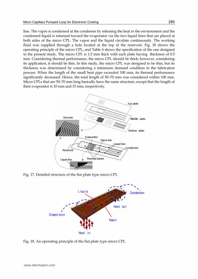
game machines, etc. However, the limit in thickness reduces the heat transfer capacity of the pressed circular type heat pipe. In addition, the thermal resistance of such pipe was greatly increased with the pressed thickness limit of 2 mm, caused by the tendency of the central part of the circular type heat pipe to be depressed when it is pressed. Another reason is the fact that it is not easy to secure sufficient space for vapor flow in a pressed heat pipe with the wick. Therefore, thin flat plate type cooling devices are needed for the thermal management of electronic packaging with limited inner space. Fig. 17 shows the micro CPL designed in the present study. The micro CPL was designed to have flat plate shape and was composed of three layers – a bottom silicon layer, a middle glass layer, and a top glass layer. The structural characteristics of the micro CPL are as follows. Contrary to the structure of a conventional heat pipe, the micro CPL is fabricated by stacking several plates. The plates with evaporator, condenser, vapour, and liquid path are fabricated by each fabrication process and then integrated in order to construct one envelope for the micro CPL. By designing the evaporator in the bottom silicon plate to have two-step structures, the large vapor flow space in it could be secured in the limited inner space of the micro CPL. By designing the upper surface of the two-step structure to interconnect with the liquid line vertically, the backflow of the vapor bubbles could be protected. The liquid flow path at the condenser was designed to have zigzag pattern and cross section, which is reduced gradually to prevent the flow pressure drop from changing abruptly in the path and to condense the vapor sufficiently. Meanwhile, the grooves in the upper glass plate were designed to have relatively large width to achieve dispersion effect of the condensed liquid on it. The bottom silicon layer was constructed out of evaporator, condenser, reservoir, and heat blocks that are placed between the evaporator and the condenser. The heat blocks reduce heat conduction via the wall and calculate the pure heat transfer rate by the vapor-liquid phase change. The fine grooves of the two-step structure were constructed in parallel at the evaporator. The middle glass layer was composed of the vapor line and vapor flow space at the part corresponding to the evaporator. The liquid lines constructed in the middle glass layer meet vertically with the upper surface of the two-step grooves at the evaporator. The operating principle of the micro CPL is slightly different from that of the heat pipe. First, the vapor created by the input power at the evaporator is transferred toward the condenser via the vapor line that is placed in the center of the micro CPL and has larger space than the liquid
www.intechopen.com
Micro Capillary Pumped Loop for Electronic Cooling 285
line. The vapor is condensed at the condenser by releasing the heat to the environment and the condensed liquid is returned toward the evaporator via the two liquid lines that are placed at both sides of the micro CPL. The vapor and the liquid circulate continuously. The working fluid was supplied through a hole located at the top of the reservoir. Fig. 18 shows the operating principle of the micro CPL, and Table 4 shows the specification of the one designed in the present study. The micro CPL is 1.5 mm thick with each plate having thickness of 0.5 mm. Considering thermal performance, the micro CPL should be thick; however, considering its application, it should be thin. In this study, the micro CPL was designed to be thin, but its thickness was determined by considering a minimum demand condition in the fabrication process. When the length of the small heat pipe exceeded 100 mm, its thermal performance significantly decreased. Hence, the total length of 50–70 mm was considered within 100 mm. Micro CPLs that are 50–70 mm long basically have the same structure, except that the length of their evaporator is 10 mm and 15 mm, respectively.
Fig. 17. Detailed structure of the flat plate type micro CPL
Fig. 18. An operating principle of the flat plate type micro CPL
Heat out
Evaporator
Vapor
Liquid Condenser
Heat in
www.intechopen.com

Heat Analysis and Thermodynamic Effects 286
Table 4. Specifications of the flat plate type micro CPL
4.2 Fabrication of the micro CPL using MEMS
Silicon was used for the bottom plate of the micro CPL, while glass was used for the middle and top plates. The silicon bottom plate, which has an evaporator with two-step grooves, a condenser, and a reservoir, was fabricated through the deep reactive ion etch (DRIE) process. The glass middle plate, which consists of the vapor space at the evaporator, the vapor line, and the feed line for supplying the working fluid into the envelope, was fabricated by wet etching and sanding processes. Meanwhile, the glass top plate with grooves for distributing the liquid at the evaporator was fabricated by the wet etching process. Fig. 19 illustrates the fabrication process flow. The detailed fabrication processes are as follows. First, the 3 µm oxide, as the masking layer, was deposited on the silicon bottom wafer through wet thermal oxidation. After the PR patterning and dry etching of the oxide layer, the oxide of 8,000Å – as the second masking layer – was deposited and patterned. Afterwards, first-step grooves (Fig. 19(a)) were etched to the depth of 60 µm by the first DRIE process. After removing the remaining PR, the second-step grooves were etched to the depth of 200 µm by the second DRIE process. The poly-silicon of 5,000 Å – as the masking layer – was deposited on the glass middle wafer to fabricate the feed line with relatively small cross-section area. After the PR patterning and dry etching of the poly-silicon layer, the grooves were etched to the depth of 60 µm by wet etching. After removing the remaining poly-silicon, the dry film resist (DFR) film was attached on the glass wafer for use as masking layer. The vapor line penetrating the glass wafer was fabricated by the sanding process (Figs. 19(b) and (c)). The grooves were then etched to the depth of 60 µm by wet etching at the evaporator in the top wafer, which is similar to the fabrication process of the middle wafer. After the grooves were fabricated, the DFR film was attached on the top glass wafer to fabricate the through hole. After patterning the DFR film, the through hole was then fabricated through the sanding process. The connection of the fill tube on the top of the glass wafer was one of the most difficult fabricating processes in the present study. The copper material was used for the fill tube like that of the general heat pipe. A fragment silicon plate on which the metal layer of circular bands shape was deposited was used for bonding with the fill tube. The metal layer has a combination of Ti/Cu/Ni. Ni of 5 µm was deposited through electroplating to guarantee that the fill tube and the metal layer are bonded firmly. The fragment silicon plate was
www.intechopen.com

Micro Capillary Pumped Loop for Electronic Cooling 287
bonded on the top glass wafer of the micro CPL by anodic bonding process. The bottom silicon wafer was bonded with the middle glass wafer by the anodic bonding process as well. The top glass wafer was bonded on the middle and bottom wafers by direct bonding process. Then the envelope for the micro CPL was completed (Fig. 20(a)). Filling the working fluid into the envelope was accomplished by the conventional method of filling after degassing. Pure water was used as working fluid. The working fluid was filled until all grooves and the liquid lines in the micro CPL were saturated; the amount of working fluid was weighed and recorded about 0.0854 g.
(a) (b) (c)
Fig. 19. The fabrication process of the flat plate type micro CPL
(a) (b) (c)
Fig. 20. Fabricated micro CPL: (a) top view of the micro CPL; (b) SEM images of grooves; and (c) SEM images of two-step grooves
4.3 Thermal performance of the micro CPL
Fig. 21 shows the experimental apparatus used to investigate the isothermal characteristics and the heat transfer rate of the fabricated micro CPL. The apparatus was composed of a vacuum chamber in which the micro CPL was placed, a data acquisition system, and a constant temperature water bath. Heat was supplied into the micro CPL electrically by DC power supply (HPS 60100 model). A heater fabricated with Ni-Cr (98.8 /m) wire with diameter of 0.08 mm was attached on the backside of the evaporator of the bottom silicon plate. The T-type thermocouples were used in order to measure the wall temperature; they were attached by epoxy to two locations on the evaporator, one location on the vapor and the liquid line, and two locations on the condenser. The heat dissipated to the environment was controlled by a liquid cooling system using water jacket that was attached on the backside of the condenser of the bottom silicon plate. The temperature and the flow rate of the cooling liquid could be controlled by the constant temperature water bath. The performance test for the fabricated micro CPL was done in a vacuum chamber in order to minimize the heat loss to the environment. The vacuum chamber was maintained to the degree of a vacuum of 2*10-1 torr during the test by continuous vacuum pumping. The
www.intechopen.com

Heat Analysis and Thermodynamic Effects 288
thermal load was supplied to the evaporator by steps of 1 or 0.5 W, starting with an initial power level of 1 W. The wall temperatures of the micro CPL in each power level were recorded when the temperatures of the wall reached a steady state. Meanwhile, visual inspection was conducted through the top glass plate in order to understand the operating characteristics of the micro CPL. The experimental results of the present study might include error rate in the measurement, i.e., the error rate in the measurement of the heat supply (±0.05 V for voltage, ±0.01 A for current) and temperature (±0.1 oC).
(a) (b)
Fig. 21. Experimental apparatus: (a) performance test system and (b) top view of the micro CPL set-up
Considering its application in portable electronic devices, the micro CPL in the present study was designed to have flat plate shape. Nevertheless, the flow pressure drop in the fluid flow path of the micro CPL may be increased because its evaporator, vapor and liquid lines, and condenser were placed in the same plane as the flat plate with thickness of 1.5 mm. The fluid flow path with reduced cross section has significant effects on the decrease in the thermal performance of small heat pipes, which depend on the flow pressure drop. For a normal operation of the micro CPL, as shown in equation (4), the total pressure drop through the loop must be less than the capillary pressure limit created at the evaporator.
(4)
Where , , and are pressure drops at the evaporator, vapor line, condenser, and liquid line, respectively. Fig. 22 shows the experimental results for the isothermal characteristic of micro CPLs with total length of 50 mm and 70 mm. The comparison results for the isothermal characteristic between the micro CPL with working fluid and the one without working fluid are shown in Fig. 22. One of the methods used to evaluate the performance of the micro CPL in the present study is by measuring the thermal resistance, R (C/W), which is defined in equation (5):
e cT TR
Q
(5)
Where eT is the mean wall temperature at the evaporator, cT is the mean wall temperature at the condenser of the micro CPL, and Q is the thermal load (W) imposed on the evaporator.
lcnvecPPPPP
eP
vP
cnP
lP
www.intechopen.com
Micro Capillary Pumped Loop for Electronic Cooling 289
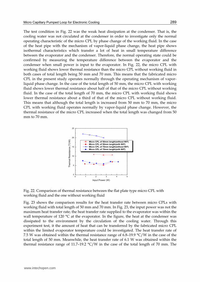
The test condition in Fig. 22 was the weak heat dissipation at the condenser. That is, the cooling water was not circulated at the condenser in order to investigate only the normal operating characteristic of the micro CPL by phase change of the working fluid. In the case of the heat pipe with the mechanism of vapor-liquid phase change, the heat pipe shows isothermal characteristics which transfer a lot of heat in small temperature difference between the evaporator and the condenser. Therefore, the normal operating state could be confirmed by measuring the temperature difference between the evaporator and the condenser when small power is input to the evaporator. In Fig. 22, the micro CPL with working fluid shows lower thermal resistance than the micro CPL without working fluid in both cases of total length being 50 mm and 70 mm. This means that the fabricated micro CPL in the present study operates normally through the operating mechanism of vapor-liquid phase change. In the case of the total length of 50 mm, the micro CPL with working fluid shows lower thermal resistance about half of that of the micro CPL without working fluid. In the case of the total length of 70 mm, the micro CPL with working fluid shows lower thermal resistance about a third of that of the micro CPL without working fluid. This means that although the total length is increased from 50 mm to 70 mm, the micro CPL with working fluid operates normally by vapor-liquid phase change. However, the thermal resistance of the micro CPL increased when the total length was changed from 50 mm to 70 mm.
0 1 2 3 4 50
5
10
15
20
25
Th
erm
al R
esis
tan
ce
(oC
/W)
Input Power (W)
Micro CPL of 50mm length(without W/F)
Micro CPL of 50mm length(with W/F)
Micro CPL of 70mm length(without W/F)
Micro CPL of 70mm length(with W/F)
Fig. 22. Comparison of thermal resistance between the flat plate type micro CPL with working fluid and the one without working fluid
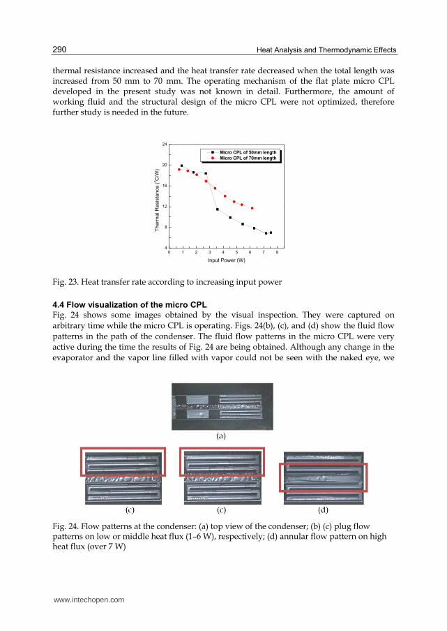
Fig. 23 shows the comparison results for the heat transfer rate between micro CPLs with working fluid with total length of 50 mm and 70 mm. In Fig. 23, the input power was not the maximum heat transfer rate; the heat transfer rate supplied to the evaporator was within the wall temperature of 120 °C at the evaporator. In the figure, the heat at the condenser was dissipated to the environment by the circulation of the cooling water. Through this experiment test, it the amount of heat that can be transferred by the fabricated micro CPL within the limited evaporator temperature could be investigated. The heat transfer rate of 7.5 W was obtained within the thermal resistance range of 6.8–19.9 °C/W in the case of the total length of 50 mm. Meanwhile, the heat transfer rate of 6.1 W was obtained within the thermal resistance range of 11.7–19.2 °C/W in the case of the total length of 70 mm. The
www.intechopen.com
Heat Analysis and Thermodynamic Effects 290
thermal resistance increased and the heat transfer rate decreased when the total length was increased from 50 mm to 70 mm. The operating mechanism of the flat plate micro CPL developed in the present study was not known in detail. Furthermore, the amount of working fluid and the structural design of the micro CPL were not optimized, therefore further study is needed in the future.
0 1 2 3 4 5 6 7 84
8
12
16
20
24
Th
erm
al R
esis
tan
ce (
oC
/W)
Input Power (W)
Micro CPL of 50mm length
Micro CPL of 70mm length
Fig. 23. Heat transfer rate according to increasing input power
4.4 Flow visualization of the micro CPL
Fig. 24 shows some images obtained by the visual inspection. They were captured on arbitrary time while the micro CPL is operating. Figs. 24(b), (c), and (d) show the fluid flow patterns in the path of the condenser. The fluid flow patterns in the micro CPL were very active during the time the results of Fig. 24 are being obtained. Although any change in the evaporator and the vapor line filled with vapor could not be seen with the naked eye, we
Fig. 24. Flow patterns at the condenser: (a) top view of the condenser; (b) (c) plug flow patterns on low or middle heat flux (1–6 W), respectively; (d) annular flow pattern on high heat flux (over 7 W)
www.intechopen.com

Micro Capillary Pumped Loop for Electronic Cooling 291
could see the fluid flow phenomenon wherein the liquid and non-condensed vapor flow together. An undesirable phenomenon wherein the vapor transported from the evaporator was condensed on the top and bottom walls in the vapor line was observed with the naked eye. The activity of two-phase flow patterns increases as the input power supplied to the evaporator is increased. The fluid flow pattern was plug flow, wherein the vapor and liquid bridge move in order, in low power (1–3 W) and middle power (4–6 W). The fluid flow pattern changed from being plug flow to annular flow in high power (7–7.5 W). The plug flow in the middle power range has larger velocity than that in the low power range. The micro CPL shows the continuous circulating flow pattern over the entire power range. The liquid drops created on the bottom and top walls at the vapor line should be removed since they may increase the pressure drop in the vapor flow.
5. Commercialization of the MHP and micro CPL
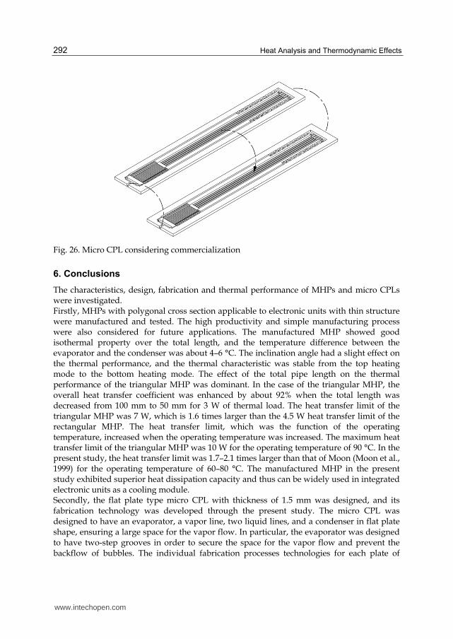
The tubular type MHP, which was considered in chapter 3, can be used in any applications and may also be packaged for high heat flux applications. The FPMHP, which was fabricated by Al extrusion, was designed with consideration of capillary force. However, for the purpose of the commercialization of the FPMHP, not only should the capillary force be considered, but also the securing of the inner space. Furthermore, the fabrication cost and fabrication process limit should also be considered. Fig. 24 shows a commercialized model of the FPMHP, which is designed with consideration of the commercial viewpoint. It may be applied to various fields like display, electronic package, automobile, and optic industry. Flat plate micro CPL, which was considered in chapter 5, may be applied to slim mobile electronic devices. The fabrication of a structure similar to design can be obtained. However, for wider application, the fabrication of micro CPL using metal, instead of silicon and glass, is needed. The cost and process of fabrication should be considered for commercialization as well. Fig. 25 shows a micro CPL model fabricated by metal for commercialization. It is composed of only two layers, compared to that considered in chapter 5 which has three layers. The most important factor is reserving the inner space for fluid flow in the case of the commercialized model shown in Fig. 25, which has thickness of less than 1 mm and is composed of only two layers.
Fig. 25. FPMHP considering commercialization
www.intechopen.com
Heat Analysis and Thermodynamic Effects 292
Fig. 26. Micro CPL considering commercialization
6. Conclusions
The characteristics, design, fabrication and thermal performance of MHPs and micro CPLs were investigated. Firstly, MHPs with polygonal cross section applicable to electronic units with thin structure were manufactured and tested. The high productivity and simple manufacturing process were also considered for future applications. The manufactured MHP showed good isothermal property over the total length, and the temperature difference between the evaporator and the condenser was about 4–6 °C. The inclination angle had a slight effect on the thermal performance, and the thermal characteristic was stable from the top heating mode to the bottom heating mode. The effect of the total pipe length on the thermal performance of the triangular MHP was dominant. In the case of the triangular MHP, the overall heat transfer coefficient was enhanced by about 92% when the total length was decreased from 100 mm to 50 mm for 3 W of thermal load. The heat transfer limit of the triangular MHP was 7 W, which is 1.6 times larger than the 4.5 W heat transfer limit of the rectangular MHP. The heat transfer limit, which was the function of the operating temperature, increased when the operating temperature was increased. The maximum heat transfer limit of the triangular MHP was 10 W for the operating temperature of 90 °C. In the present study, the heat transfer limit was 1.7–2.1 times larger than that of Moon (Moon et al., 1999) for the operating temperature of 60–80 °C. The manufactured MHP in the present study exhibited superior heat dissipation capacity and thus can be widely used in integrated electronic units as a cooling module. Secondly, the flat plate type micro CPL with thickness of 1.5 mm was designed, and its fabrication technology was developed through the present study. The micro CPL was designed to have an evaporator, a vapor line, two liquid lines, and a condenser in flat plate shape, ensuring a large space for the vapor flow. In particular, the evaporator was designed to have two-step grooves in order to secure the space for the vapor flow and prevent the backflow of bubbles. The individual fabrication processes technologies for each plate of
www.intechopen.com

Micro Capillary Pumped Loop for Electronic Cooling 293
silicon and glass were developed. Particularly, the bonding technology of the fill tube on the glass top plate was completed by the fragment silicon on which the circular type metal bands were deposited. The filling technology of the working fluid into the micro CPL under vacuum condition was completed by the conventional method of filling after vacuuming. Through the performance tests for the fabricated micro CPLs with total length of 50 mm and 70 mm, it was confirmed that micro CPLs operate normally through the phase-change heat transfer of the vapor and liquid. The thermal resistance of the micro CPL increased and the heat transfer rate decreased within the wall temperature of 120 °C at the evaporator when the total length increased from 50 mm to 70 mm. Through the visual study, it was observed that the fluid flow pattern of the micro CPL was plug flow in the low (1–3 W) and middle (4–6 W) power, and annular flow in the high power (over 7 W). The velocity of the fluid flow increased according to the input power. Further study on determining the operating mechanism of the flat plate type micro CPL and optimizing the structural design is needed in the future.
7. References
A. Faghri, "Heat Pipe Science and Technology," Talor & Francis, 1995 A. Hoelke, et al., “Analysis of the Heat Transfer Capacity of a Micromachined Loop Heat
Pipe,” ASME 1999, Vol. 3, 1999, pp.53-60 B. R. Babin, et al., "Steady-State Modeling and Testing of a Micro Heat Pipe," ASME J. of Heat
Transfer, Vol. 112, No. 3, August, pp. 595~601, 1990 D. Wu, et al., "Investigation of the Transient Characteristics of a Micro Heat Pipe," AIAA J.
Thermophysics Heat Transfer, 5(2), April, pp. 129~134, 1991 F. M. Gerner, "Flow Limitation in Micro Heat Pipes," AFSOR Final Report, No. F49620-88-6-
0053, Wright-Patterson, AFB, Dayton, OH, 1989 G. P. Peterson, “An Introduction to Heat Pipes: Modeling, Testing and Applications,” Wiley:
New York, NY, 1994 H. Xie, et al., “The Use of Heat Pipes in the Cooling of Portables with High Power
Packages,” Thermacore Co., Technical Note J. Kirshberg, et al., “Cooling Effect of a MEMS Based Micro Capillary Pumped Loop for
Chip-Level Temperature Control,” ASME 2000, MEMS Vol.2, 2000, pp.143-150 J. S. Suh, et al., “Friction in Micro-Channel Flows of a Liquid and Vapor in Trapezoidal and
Sinusoidal Grooves,” Int. J. of Heat & Mass Transfer, Vol. 44, 2001, pp.3103-3109 K. S. Kim, S. H. Moon, C. G. Choi, “Cooling Characteristics of Miniature Heat Pipes with
Woven-Wired Wick,” 11th Int. Heat Pipe Conf., Japan, Sep. 1999 L. Meyer, et al., “A Silicon-Carbide Micro-Capillary Pumped Loop for Cooling High Power
Devices,” 19th IEEE Semi-Therm Symp., 2003, pp.364-368 M. C. Zaghdoudi, et al., “Theoretical Investigation of Micro Heat Pipes Performance,” 10th
Int. Heat Pipe Conf., Germany, Sep. 21-25, F-9, 1997 R. Hopkins, et al., “Flat Miniature Heat Pipe with Micro Capillary Grooves,” Transaction of
the ASME, Vol. 121, pp. 102-109, 1999 S. H. Moon, G. Hwang, H. G. Yun, T. G. Choy, “Operation Performance of Miniature Heat
Pipe with Composite Wire Wick,” IMAPS 2001, pp. 207-211, 2001 S. H. Moon, G. Hwang, H. G. Yun, “Improving Thermal Performance of Miniature Heat
Pipe for Notebook PC Cooling,” Microelectronic Reliability, Vol.42, No.1, 2002
www.intechopen.com

Heat Analysis and Thermodynamic Effects 294
S. H. Moon, et al., “An Experimental Study on The Performance Limitation of a Micro Heat Pipe with Triangular cross-section,” 11th Int. Heat Pipe Conf., Japan, Sep. 1999
S. H. Moon, et al., “Heat Transport Performance of Micro Heat Pipe with Cross Section of Polygon,” IMAPAS 2002, Int. Symposium on Microelectronics, Session WP4, 2002
S. H. Moon, et al., “Manufacturing and Thermal Performance of the Flat Plate Micro Heat Pipe,” IMAPS ATW on Thermal Management for High Performance Computing Telcom/Wireless, 2002
T.P. Cotter, "Principles and Prospects for Micro Heat Pipes", Proceedings of the 5th Int. Heat Pipe Conference, 1984.
www.intechopen.com
Heat Analysis and Thermodynamic EffectsEdited by Dr. Amimul Ahsan
ISBN 978-953-307-585-3Hard cover, 394 pagesPublisher InTechPublished online 22, September, 2011Published in print edition September, 2011
InTech EuropeUniversity Campus STeP Ri Slavka Krautzeka 83/A 51000 Rijeka, Croatia Phone: +385 (51) 770 447 Fax: +385 (51) 686 166www.intechopen.com
InTech ChinaUnit 405, Office Block, Hotel Equatorial Shanghai No.65, Yan An Road (West), Shanghai, 200040, China
Phone: +86-21-62489820 Fax: +86-21-62489821
The heat transfer and analysis on heat pipe and exchanger, and thermal stress are significant issues in adesign of wide range of industrial processes and devices. This book includes 17 advanced and revisedcontributions, and it covers mainly (1) thermodynamic effects and thermal stress, (2) heat pipe and exchanger,(3) gas flow and oxidation, and (4) heat analysis. The first section introduces spontaneous heat flow,thermodynamic effect of groundwater, stress on vertical cylindrical vessel, transient temperature fields,principles of thermoelectric conversion, and transformer performances. The second section coversthermosyphon heat pipe, shell and tube heat exchangers, heat transfer in bundles of transversely-finnedtubes, fired heaters for petroleum refineries, and heat exchangers of irreversible power cycles. The thirdsection includes gas flow over a cylinder, gas-solid flow applications, oxidation exposure, effects of buoyancy,and application of energy and thermal performance index on energy efficiency. The forth section presentsintegral transform and green function methods, micro capillary pumped loop, influence of polyisobutyleneadditions, synthesis of novel materials, and materials for electromagnetic launchers. The advanced ideas andinformation described here will be fruitful for the readers to find a sustainable solution in an industrializedsociety.
How to referenceIn order to correctly reference this scholarly work, feel free to copy and paste the following:
Seok-Hwan Moon and Gunn Hwang (2011). Micro Capillary Pumped Loop for Electronic Cooling, HeatAnalysis and Thermodynamic Effects, Dr. Amimul Ahsan (Ed.), ISBN: 978-953-307-585-3, InTech, Availablefrom: http://www.intechopen.com/books/heat-analysis-and-thermodynamic-effects/micro-capillary-pumped-loop-for-electronic-cooling

© 2011 The Author(s). Licensee IntechOpen. This chapter is distributedunder the terms of the Creative Commons Attribution-NonCommercial-ShareAlike-3.0 License, which permits use, distribution and reproduction fornon-commercial purposes, provided the original is properly cited andderivative works building on this content are distributed under the samelicense.