micro controller x communication functions (rs … modbus protocol.pdf · instruction manual...
TRANSCRIPT
Instruction Manual
INP-TN512642a-E
MICRO CONTROLLER X COMMUNICATION FUNCTIONS (RS-485 MODBUS) TYPE: PXR

NOTICE 1. Exemption items from responsibility The contents of this document may be changed in the future without prior notice. We paid the utmost care for the accuracy of the contents. However, we are not liable for direct and
indirect damages resulting from incorrect descriptions, omission of information, and use of information in this document.
-i-
CONTENTS 1. COMMUNICATION FUNCTIONS ・・・・・・・・・・・・・・・・・・・・・・・・・・・・・・・・・・・・・・・・・・・・・・・・・・・・・・・・・・・・・・・ 1
1.1 General ・・・・・・・・・・・・・・・・・・・・・・・・・・・・・・・・・・・・・・・・・・・・・・・・・・・・・・・・・・・・・・・・・・・・・・・・・・・・・・・・・・・ 1
2. SPECIFICATIONS ・・・・・・・・・・・・・・・・・・・・・・・・・・・・・・・・・・・・・・・・・・・・・・・・・・・・・・・・・・・・・・・・・・・・・・・・・・・・ 2 2.1 Communication Specifications・・・・・・・・・・・・・・・・・・・・・・・・・・・・・・・・・・・・・・・・・・・・・・・・・・・・・・・・・・・・・・・・・ 2
3. CONNECTION ・・・・・・・・・・・・・・・・・・・・・・・・・・・・・・・・・・・・・・・・・・・・・・・・・・・・・・・・・・・・・・・・・・・・・・・・・・・・・・・ 3 3.1 Terminal Allocation ・・・・・・・・・・・・・・・・・・・・・・・・・・・・・・・・・・・・・・・・・・・・・・・・・・・・・・・・・・・・・・・・・・・・・・・・・ 3 3.2 Wiring・・・・・・・・・・・・・・・・・・・・・・・・・・・・・・・・・・・・・・・・・・・・・・・・・・・・・・・・・・・・・・・・・・・・・・・・・・・・・・・・・・・・ 4
4. SETTING OF COMMUNICATION CONDITION・・・・・・・・・・・・・・・・・・・・・・・・・・・・・・・・・・・・・・・・・・・・・・・・・・・・ 5 4.1 Set Items ・・・・・・・・・・・・・・・・・・・・・・・・・・・・・・・・・・・・・・・・・・・・・・・・・・・・・・・・・・・・・・・・・・・・・・・・・・・・・・・・・・ 5 4.2 Setting Operation Method・・・・・・・・・・・・・・・・・・・・・・・・・・・・・・・・・・・・・・・・・・・・・・・・・・・・・・・・・・・・・・・・・・・・・ 6
5. MODBUS COMMUNICATION PROTOCOL ・・・・・・・・・・・・・・・・・・・・・・・・・・・・・・・・・・・・・・・・・・・・・・・・・・・・・・・ 7 5.1 General ・・・・・・・・・・・・・・・・・・・・・・・・・・・・・・・・・・・・・・・・・・・・・・・・・・・・・・・・・・・・・・・・・・・・・・・・・・・・・・・・・・・ 7 5.2 Composition of Message・・・・・・・・・・・・・・・・・・・・・・・・・・・・・・・・・・・・・・・・・・・・・・・・・・・・・・・・・・・・・・・・・・・・・・ 8 5.3 Response of Slave Station・・・・・・・・・・・・・・・・・・・・・・・・・・・・・・・・・・・・・・・・・・・・・・・・・・・・・・・・・・・・・・・・・・・・ 10 5.4 Function Code・・・・・・・・・・・・・・・・・・・・・・・・・・・・・・・・・・・・・・・・・・・・・・・・・・・・・・・・・・・・・・・・・・・・・・・・・・・・・ 11 5.5 Calculation of Error Check Code (CRC-16)・・・・・・・・・・・・・・・・・・・・・・・・・・・・・・・・・・・・・・・・・・・・・・・・・・・・・・ 12 5.6 Transmission Control Procedure・・・・・・・・・・・・・・・・・・・・・・・・・・・・・・・・・・・・・・・・・・・・・・・・・・・・・・・・・・・・・・・ 13 5.7 FIX Processing (Cautions at write-in of data) ・・・・・・・・・・・・・・・・・・・・・・・・・・・・・・・・・・・・・・・・・・・・・・・・・・・・ 15
6. DETAILS OF MESSAGE ・・・・・・・・・・・・・・・・・・・・・・・・・・・・・・・・・・・・・・・・・・・・・・・・・・・・・・・・・・・・・・・・・・・・・・ 16 6.1 Read-out of Bit Data [Function code:01H] ・・・・・・・・・・・・・・・・・・・・・・・・・・・・・・・・・・・・・・・・・・・・・・・・・・・・ 16 6.2 Read-out of Read-out Only Bit Data [Function code:02H]・・・・・・・・・・・・・・・・・・・・・・・・・・・・・・・・・・・・・・・・・・・・・ 17 6.3 Read-out of Word Data [Function code:03H]・・・・・・・・・・・・・・・・・・・・・・・・・・・・・・・・・・・・・・・・・・・・・・・・・・・・ 19 6.4 Read-out of Read-out Only Word Data [Function code:04H]・・・・・・・・・・・・・・・・・・・・・・・・・・・・・・・・・・・・・・・・・・ 22 6.5 Write-in of Bit Data (1 bit) [Function code:05H]・・・・・・・・・・・・・・・・・・・・・・・・・・・・・・・・・・・・・・・・・・・・・・・・・ 24 6.6 Write-in of Word Data (1 word) [Function code:06H] ・・・・・・・・・・・・・・・・・・・・・・・・・・・・・・・・・・・・・・・・・・・・・・ 25 6.7 Write-in of Continuous Word Data [Function code:10H] ・・・・・・・・・・・・・・・・・・・・・・・・・・・・・・・・・・・・・・・・・・ 26
7. ADDRESS MAP AND DATA FORMAT ・・・・・・・・・・・・・・・・・・・・・・・・・・・・・・・・・・・・・・・・・・・・・・・・・・・・・・・・・・ 28 7.1 Data Format ・・・・・・・・・・・・・・・・・・・・・・・・・・・・・・・・・・・・・・・・・・・・・・・・・・・・・・・・・・・・・・・・・・・・・・・・・・・・・・ 28 7.2 Address Map of Internal Calculation Value Data・・・・・・・・・・・・・・・・・・・・・・・・・・・・・・・・・・・・・・・・・・・・・・・・・・ 31 7.3 Address Map of Engineering Unit Data ・・・・・・・・・・・・・・・・・・・・・・・・・・・・・・・・・・・・・・・・・・・・・・・・・・・・・・・・・ 36 7.4 Additional Explanation of Address Map ・・・・・・・・・・・・・・・・・・・・・・・・・・・・・・・・・・・・・・・・・・・・・・・・・・・・・・・・ 41
8. SAMPLE PROGRAM ・・・・・・・・・・・・・・・・・・・・・・・・・・・・・・・・・・・・・・・・・・・・・・・・・・・・・・・・・・・・・・・・・・・・・・・・・ 44
9. TROUBLESHOOTING・・・・・・・・・・・・・・・・・・・・・・・・・・・・・・・・・・・・・・・・・・・・・・・・・・・・・・・・・・・・・・・・・・・・・・・・ 49

-1-
1. COMMUNICATION FUNCTIONS 1.1 General
• PXR provides a communication function by RS-485 interface, by which it can transmit and receive data to and from host computer, programmable controller, graphic display panel, etc.
• The communication system consists of master station and slave stations. Up to 31 slave stations (PXR) can
be connected per master station. Note that, because the master station can communicate with only one slave station at a time, a party to communicate with must be specified by the "Station No." set at each slave station.
• In order that the master station and slave station can communicate, the format of the transmit/receive data must
coincide. For the PXR, the format of the communication data is determined by the MODBUS protocol. • Please use an RS-232C↔RS-485 converter in case of designating a personal computer or other devices which
have an RS-232C interface as a master station. [RS-232C↔RS-485 converter] (recommended article)
Type: KS-485 (non-isolated type)/SYSTEM SACOM Corp. Type: SI-30A (isolated type)/SEKISUI ELECTRONICS Co., Ltd.
RS-485
RS-232C
Personalcomputer
RS-232C RS-485 converter
RS-485
Programmablecontroller�
[Note] MODBUS® is the registered trade mark of Gould Modicon.
-2-
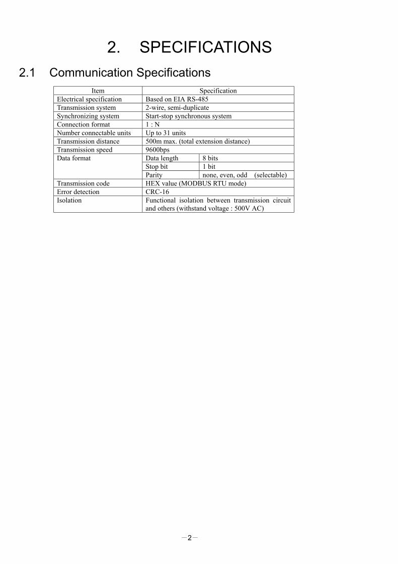
2. SPECIFICATIONS 2.1 Communication Specifications
Item Specification Electrical specification Based on EIA RS-485 Transmission system 2-wire, semi-duplicate Synchronizing system Start-stop synchronous system Connection format 1 : N Number connectable units Up to 31 units Transmission distance 500m max. (total extension distance) Transmission speed 9600bps
Data length 8 bits Stop bit 1 bit
Data format
Parity none, even, odd (selectable) Transmission code HEX value (MODBUS RTU mode) Error detection CRC-16 Isolation Functional isolation between transmission circuit
and others (withstand voltage : 500V AC)

-3-
3. CONNECTION WARNING
For avoiding electric shock and malfunctions, do not turn on the power supply untill all wiring have been completed.
3.1 Terminal Allocation Terminal number Signal name
7 + 8 -

-4-
3.2 Wiring • Use twisted pair cables with shield. Recommended cable: UL2464, UL2448, etc. • The total extension length of the cable is up to 500 m. A master station and up to 31 units of the PXR can be
connected per line. • Both ends of the cable should be terminate with terminating resistors 100Ω1/2W. • The shield wire of the cable should be grounded at one place on the master station unit side. • If the PXR is to be installed where the level of noise applied to the PXR may exceed 1000 V, it is
recommended to install a noise filter in the master station side as below. Recommended noise filter: ZRAC2203-11/TDK
TransmissioncableRS-232C⇔RS-485 Noise filter PXR
Master station(PC, etc.)
7
8
+
-
Slave station (PXR)
Twisted pair cable with shield
Terminating resistor100Ω(1/2W)
RS-485 interfaceor
RS-485 side of the RS-232C RS-485 converter
Terminating resistor100Ω(1/2W)
Master station side
FG
-
7
8
+
-
Slave station (PXR)
7
8
+
-
Slave station (PXR)
-5-
4. SETTING OF COMMUNICATION CONDITION In order that the master station and instrument (PXR) can correctly communicate, following settings are required.
• All communication condition settings of the master station are the same as those of instruments (PXR). • All instruments (PXR) connected on a line are set to "Station Nos. (STno)" which are different from each other.
(Any "Station No." is not shared by more than one instrument.)
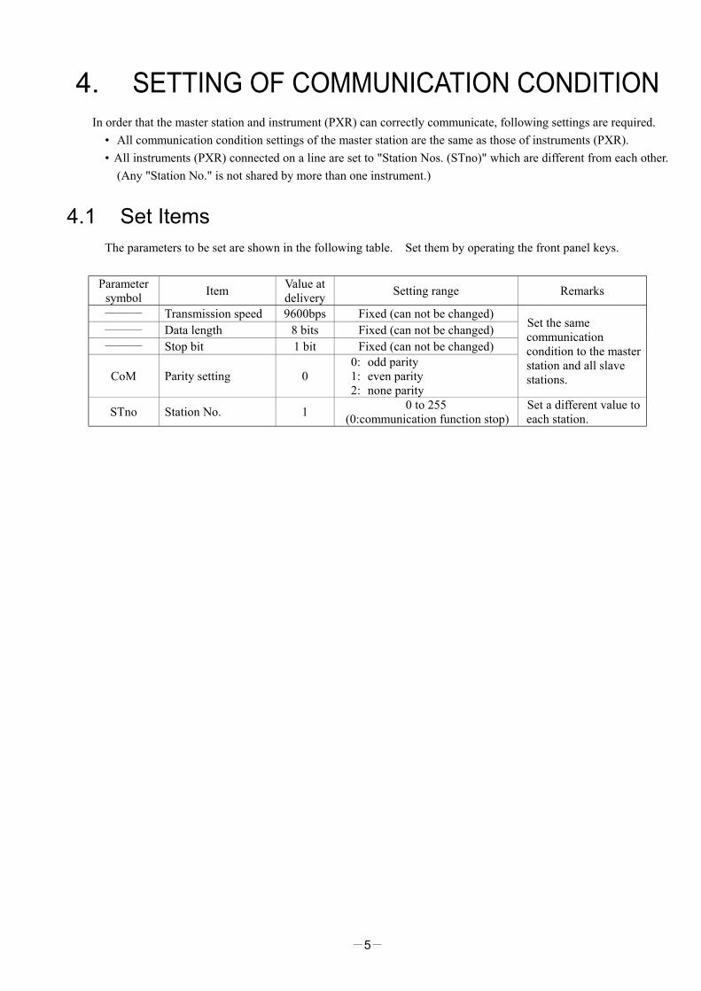
4.1 Set Items The parameters to be set are shown in the following table. Set them by operating the front panel keys.
Parameter symbol Item Value at
delivery Setting range Remarks
――― Transmission speed 9600bps Fixed (can not be changed) ――― Data length 8 bits Fixed (can not be changed) ――― Stop bit 1 bit Fixed (can not be changed)
CoM Parity setting 0 0: odd parity 1: even parity 2: none parity
Set the same communication condition to the master station and all slave stations.
STno Station No. 1 0 to 255 (0:communication function stop)
Set a different value to each station.

-6-
4.2 Setting Operation Method The following example shows how to set the communication conditions. Example: Selecting an even parity and “STno=18” on a station.
Key operation Indication Description
200200
Running state (PV/SV indication)
SEL (6 seconds)
P-n10
Press the SEL key for approximately 6 seconds. P-n1 appears and No. 3 block parameter is selected.
∨ STno0
Operate the ∨ key repeatedly until STno parameter appears. (If past over, operate the ∧ key to return.)
SEL STno0
Press the SEL key. The numeric value on the lower indicator blinks and the setting mode is selected.
∧∨ STno18 Operate the ∧ or ∨ key to change the numeric value to 18.
SEL STno18
Press the SEL key again. The numeric value stops blinking and the setting is registered.
∨ CoM0 Press the ∨ key to display the CoM parameter.
SEL CoM0
Press the SEL key. The numeric value on the lower indicator blinks and the setting mode is selected.
∧∨ CoM1
Operate the ∧ or ∨ key until the numeric value changes to 1 (even parity).
SEL CoM1
Press the SEL key again. The numeric value stops blinking and the setting is registered.
SEL (3 seconds)
200200
Press the SEL key for 3 seconds to resume the running indication (PV/SV indication).
-7-
5. MODBUS COMMUNICATION PROTOCOL 5.1 General
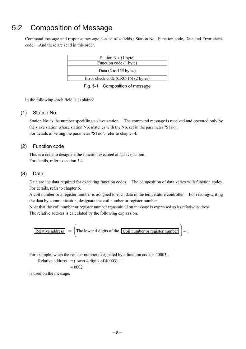
The communication system by the MODBUS protocol is that the communication is always started from the master station and a slave station responds to the received message.
Transmission procedures is as shown below. 1) The master station sends a command message to a slave station. 2) The slave station checks that the station No. in the received message matches with the own station No. or
not. 3) If matched, the slave station executes the command and sends back the response message. 4) If mismatched, the slave station leaves the command message and wait for the next command message.
a) In case when the station No. in the received command message matches with the own slave station No.
Command messageResponse messageSlave to master
Master to slave Data onthe line
b) In case when the station No. in the received command message mismatches with the own slave station
No.
Command message(Not respond)Slave to master
Master to slave Data onthe line
The master station can individually communicate with any one of slave stations connected on the same line upon setting the station No. in the command message.
-8-
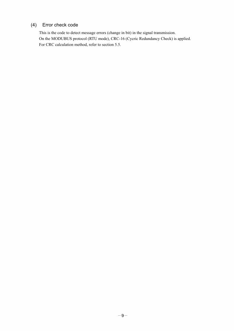
5.2 Composition of Message Command message and response message consist of 4 fields ; Station No., Function code, Data and Error check code. And these are send in this order.
Station No. (1 byte) Function code (1 byte)
Data (2 to 125 bytes)
Error check code (CRC-16) (2 bytes)
Fig. 5-1 Composition of message
In the following, each field is explained.
(1) Station No. Station No. is the number specifiing a slave station. The command message is received and operated only by the slave station whose station No. matches with the No. set in the parameter "STno". For details of setting the parameter "STno", refer to chapter 4.
(2) Function code This is a code to designate the function executed at a slave station. For details, refer to section 5.4.
(3) Data Data are the data required for executing function codes. The composition of data varies with function codes. For details, refer to chapter 6. A coil number or a register number is assigned to each data in the temperature controller. For reading/writing the data by communication, designate the coil number or register number. Note that the coil number or register number transmitted on message is expressed as its relative address. The relative address is calculated by the following expression.
Relative address =
The lower 4 digits of the
Coil number or register number – 1
For example, when the resister number designated by a function code is 40003, Relative address = (lower 4 digits of 40003) – 1 = 0002 is used on the message.
-9-
(4) Error check code This is the code to detect message errors (change in bit) in the signal transmission. On the MODUBUS protocol (RTU mode), CRC-16 (Cycric Redundancy Check) is applied. For CRC calculation method, refer to section 5.5.

-10-
5.3 Response of Slave Station (1) Response for normal command
To a relevant message, the slave station creates and sends back a response message which corresponds to the command message. The composition of message in this case is the same as in section 5.2. Contents of the data field depend on the function code. For details, refer to Chapter 6.
(2) Response for abnormal command If contents of a command message have an abnormality (for example, non-actual function code is designated) other than transmission error, the slave station does not execute that command but creates and sends back a response message at error detection. The composition of response message at error detection is as shown in Fig. 5-2 The value used for function code field is function code of command message plus 80H. Table 5-1 gives error codes.
Station No. Function code + 80H
Error code Error check(CRC-16)
Fig. 5-2 Response message at error detection
Table 5-1 Error code
Error code Contents Description 01H Illegal function Non-actual function code is designated.
Check for the function code. 02H Illegal data address A relative address of a coil number or resister
number to which the designated function code can not be used.
03H Illegal data value Because the designation of number is too much, the area where coil numbers or resister numbers do not exist is designated.
(3) No response
Under any of the following items, the slave station takes no action of the command message and sends back no response.
・A station number transmitted in the command message differs from the station number specified to the slave station.
・ A error check code is not matched, or a transmission error (parity error, etc.) is detected. ・ The time interval between the composition data of the message becomes longer than the time
corresponding to 24 bits. (Refer to section 5.6 Transmission Control Procedure) ・While the data is being written in non-volatile memory after write via communication, the next write is
attempted.
-11-
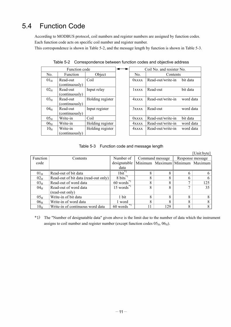
5.4 Function Code According to MODBUS protocol, coil numbers and register numbers are assigned by function codes. Each function code acts on specific coil number and register number. This correspondence is shown in Table 5-2, and the message length by function is shown in Table 5-3.
Table 5-2 Correspondence between function codes and objective address
Function code Coil No. and resister No. No. Function Object No. Contents 01H Read-out
(continuously) Coil 0xxxx Read-out/write-in bit data
02H Read-out (continuously)
Input relay 1xxxx Read-out bit data
03H Read-out (continuously)
Holding register 4xxxx Read-out/write-in word data
04H Read-out (continuously)
Input register 3xxxx Read-out word data
05H Write-in Coil 0xxxx Read-out/write-in bit data 06H Write-in Holding register 4xxxx Read-out/write-in word data 10H Write-in
(continuously) Holding register 4xxxx Read-out/write-in word data
Table 5-3 Function code and message length
[Unit:byte] Command message Response message Function
code Contents Number of
designatable data
Minimum Maximum Minimum Maximum
01H Read-out of bit data 1bit*1 8 8 6 6 02H Read-out of bit data (read-out only) 8 bits*1 8 8 6 6 03H Read-out of word data 60 words*1 8 8 7 125 04H Read-out of word data
(read-out only) 15 words*1 8 8 7 35
05H Write-in of bit data 1 bit 8 8 8 8 06H Write-in of word data 1 word 8 8 8 8 10H Write-in of continuous word data 60 words *1 11 129 8 8
*1) The "Number of designatable data" given above is the limit due to the number of data which the instrument
assigns to coil number and register number (except function codes 05H, 06H).
-12-
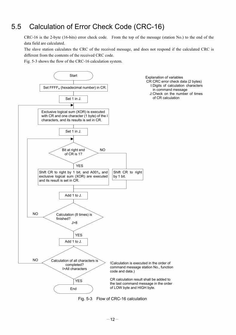
5.5 Calculation of Error Check Code (CRC-16) CRC-16 is the 2-byte (16-bits) error check code. From the top of the message (station No.) to the end of the data field are calculated. The slave station calculates the CRC of the received message, and does not respond if the calculated CRC is different from the contents of the received CRC code. Fig. 5-3 shows the flow of the CRC-16 calculation system.
NO
NO
YES
YES
NO
YES
Start
Set 1 in J.
Set 1 in J.
Bit at right endof CR is 1?
Shift CR to right by 1 bit, and A001H andexclusive logical sum (XOR) are executedand its result is set in CR.
Shift CR to rightby 1 bit.
Add 1 to J.
Add 1 to J.
End
Explanation of variablesCR:CRC error check data (2 bytes)
I:Digits of calculation charactersin command message
J:Check on the number of timesof CR calculation
(Calculation is executed in the order ofcommand message station No., functioncode and data.)
CR calculation result shall be added tothe last command message in the orderof LOW byte and HIGH byte.
Set FFFFH (hexadecimal number) in CR.
Calculation (8 times) isfinished?
J>8
Calculation of all characters iscompleted?
I>All characters
Exclusive logical sum (XOR) is executedwith CR and one character (1 byte) of the Icharacters, and its results is set in CR.
Fig. 5-3 Flow of CRC-16 calculation
-13-
5.6 Transmission Control Procedure (1) Transmission procedure of master station
The master station must proceed to a communication upon conforming to the following items. (1-1) Before sending a command message, provide 48 bits time or more vacant status. (1-2) For sending, the interval between bytes of a command message is below 24 bits time. (1-3) Within 24 bits time after sending a command message, the receiving status is posted. (1-4) Provide 48 bits time or more vacant status between the end of response message reception and
beginning of next command message sending [same as in (1-1)]. (1-5) For ensuring the safety, make a confirmation of the response message and make an arrangement so
as to provide 3 or more retries in case of no response, error occurrence, etc. Note) The above definition is for most unfavorable value. For ensuring the safety, it’s recommended the
program of the master to work with safety factors of 2 to 3. Concretely, it is advised to arrange the program for 9600 bps with 10 ms or more for vacant status (1-1), and within 1 ms for byte interval (1-2) and changeover from sending to receiving (1-3).
(2) Description
1) Detection of the message frame Since the communication system uses the 2-wire RS-485 interface, there may be 2 statuses on a line below.
(a) Vacant status (no data on line) (b) Communication status (data is existing)
Instruments connected on the line are initially at a receiving status and monitoring the line. When 24 bits time or more vacant status has appeared on the line, the end of preceding frame is assumed and, within following 24 bits time, a receiving status is posted. When data appears on the line, instruments receive it while 24 bits time or more vacant status is detected again, and the end of that frame is assumed. I.e., data which appeared on the line from the first 24 bits time or more vacant status to the next 24 bits time or more vacant status is fetched as one frame. Therefore, one frame (command message) must be sent upon confirming the following.
(1-1) 48 bits time or more vacant status precedes the command message sending. (1-2) Interval between bytes of 1 command message is smaller than 24 bits time.
2) Response of this instrument (PXR)
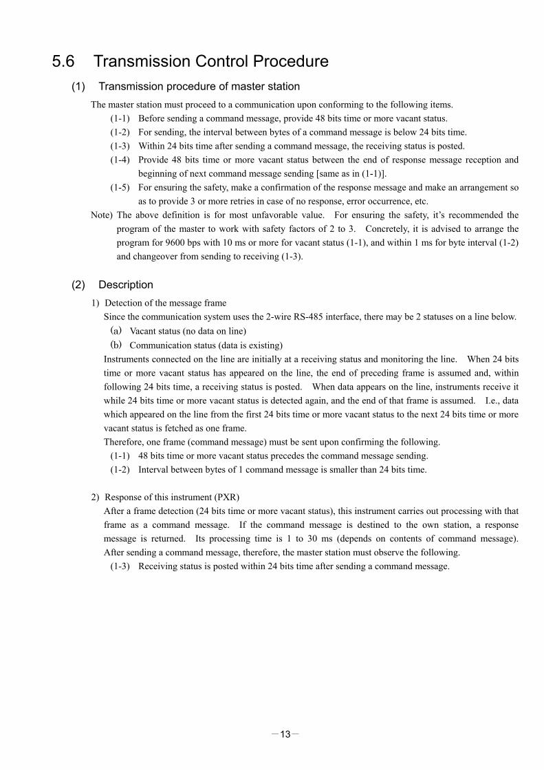
After a frame detection (24 bits time or more vacant status), this instrument carries out processing with that frame as a command message. If the command message is destined to the own station, a response message is returned. Its processing time is 1 to 30 ms (depends on contents of command message). After sending a command message, therefore, the master station must observe the following.
(1-3) Receiving status is posted within 24 bits time after sending a command message.
-14-
POL1 POL2
POL1 POL2 POL1 response data
POL1 response data
Space time of longer than 5ms is needed (longer than 10ms is recommended)
1 to 30msec
Master station → PXR
Master station ← PXR
Data on line
-15-
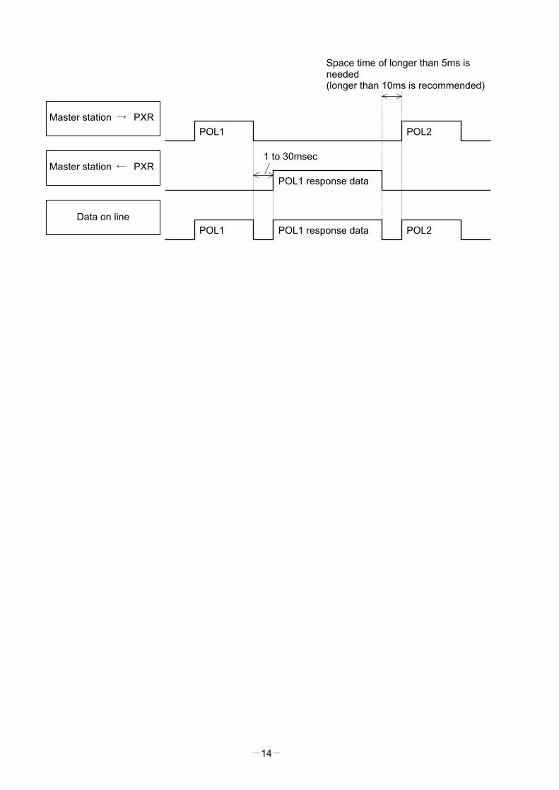
5.7 FIX Processing (Cautions at write-in of data) The instrument is provided inside with a non-volatile memory (EEPROM) for holding the setting parameters. Data written in the non-volatile memory is not lost even if turning off the power. When setting parameter is written via communication, the data is stored in the internal memory (RAM) and then written in the non-volatile memory. FIX execution writes the parameters stored in the internal memory into the non-volatile memory, but this function is not required any more because the data is written in non-volatile memory when it is written in the parameter. Fig. 5-4 shows the FIX procedure. Cautions: ・ Write in the non-volatile memory takes approximately 5 seconds at the longest approximately 5 seconds. ・ While writing, do not turn off the power of the PXR. Otherwise, the data in the non-volatile memory will
be destroyed, whereby the PXR could not be used any longer. ・ The non-volatile memory (EEPROM) is a device where the number of write-in times is limited. The
guaranteed number of write-in times of the non-volatile memory used on the instrument is 10,000 minimum. Therefore, limit the times of change of parameter setting to absolute minimum. Refrain from carrying out the FIX processing periodically for example or while such is not absolutely required.
Start FIX
Read the FIX bitwith function code : 01H
relative address : 0000H
FIX=0?
Write ‘1’ into FIX bitwith function code : 05H
relative address : 0000H
Read the FIX bitwith function code : 01H
relative address : 0000H
FIX=0?
End FIX
No
Yes
No
Yes
Fig. 5-4 FIX procedure

-16-
6. DETAILS OF MESSAGE 6.1 Read-out of Bit Data [Function code:01H]
Function code Max. bit number read-out in one message Relative data address Coil number 01H 1 bit 0000H 00001
(1) Message composition
Command message composition (byte) Response message composition (byte) Station No. Station No. Function code Function code
00H Read-out start No. (relative address) 00H 01H
00H State of the first 8 bits Read-out bit number 01H Upper Upper CRC data Lower CRC data Lower
* Arrangement of read-out bit data
MSB LSB 0 0 0 0 0 0 0
State of read-out bit
(2) Function explanations The state of the bit of the coil No. 00001 is read-out.
(3) Message transmission (example) The following shows an example of reading-out the FIX execution request data from No. 1 slave station. FIX execution request bit Relative address:0000H Number of data:01H
Command message composition (byte) Response message composition (byte) Station No.. 01H Station No. 01H Function code 01H Function code 01H
Upper 00H Read-out byte number 01H Read-out start No. (relative address) Lower 00H State of the first 8 bits 00H
Upper 00H Upper 51H Read-out bit number Lower 01H CRC data Lower 88H
Upper FDH CRC data Lower CAH * Meaning of read data MSB LSB State of FIX execution request 00H= 0 0 0 0 0 0 0 0 ↑ No execution of FIX
-17-
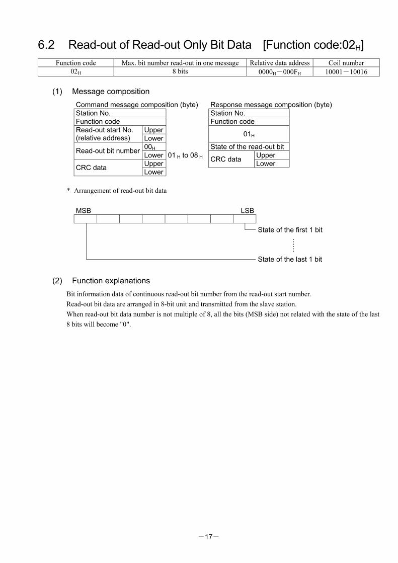
6.2 Read-out of Read-out Only Bit Data [Function code:02H] Function code Max. bit number read-out in one message Relative data address Coil number
02H 8 bits 0000H-000FH 10001-10016
(1) Message composition Command message composition (byte) Response message composition (byte) Station No. Station No. Function code Function code
Upper Read-out start No. (relative address) Lower 01H
00H State of the read-out bit Read-out bit number Lower 01 H to 08 H Upper Upper CRC data Lower CRC data Lower
* Arrangement of read-out bit data
MSB LSB
State of the first 1 bit
……
State of the last 1 bit
(2) Function explanations Bit information data of continuous read-out bit number from the read-out start number. Read-out bit data are arranged in 8-bit unit and transmitted from the slave station. When read-out bit data number is not multiple of 8, all the bits (MSB side) not related with the state of the last 8 bits will become "0".
-18-
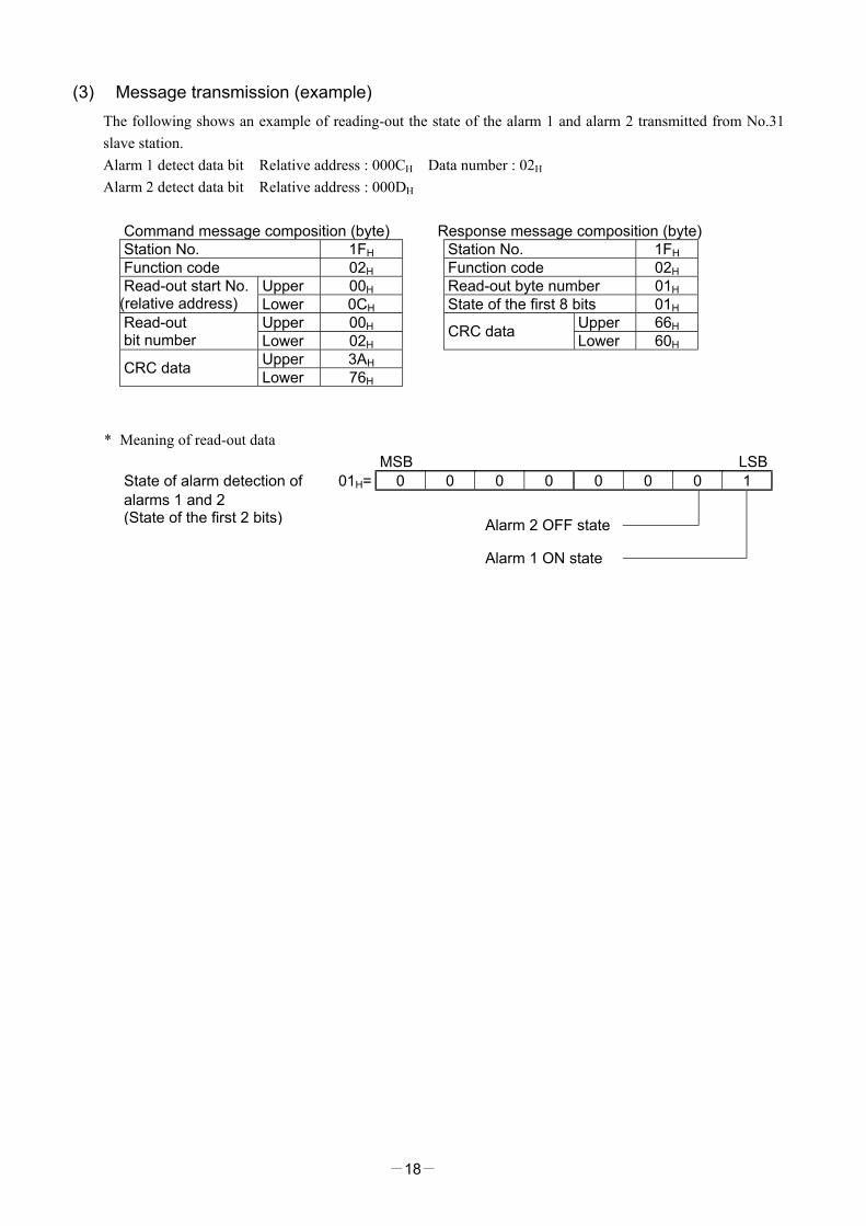
(3) Message transmission (example) The following shows an example of reading-out the state of the alarm 1 and alarm 2 transmitted from No.31 slave station. Alarm 1 detect data bit Relative address : 000CH Data number : 02H Alarm 2 detect data bit Relative address : 000DH
Command message composition (byte) Response message composition (byte) Station No. 1FH Station No. 1FH Function code 02H Function code 02H
Upper 00H Read-out byte number 01H Read-out start No. (relative address) Lower 0CH State of the first 8 bits 01H
Upper 00H Upper 66H Read-out bit number Lower 02H CRC data Lower 60H
Upper 3AH CRC data Lower 76H * Meaning of read-out data
MSB LSB State of alarm detection of 01H= 0 0 0 0 0 0 0 1 alarms 1 and 2 (State of the first 2 bits) Alarm 2 OFF state Alarm 1 ON state
-19-
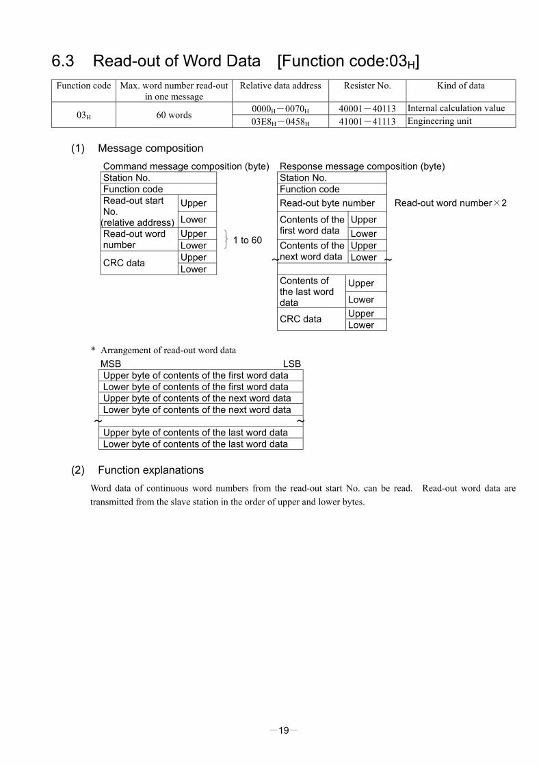
6.3 Read-out of Word Data [Function code:03H] Function code Max. word number read-out
in one message Relative data address Resister No. Kind of data
0000H-0070H 40001-40113 Internal calculation value 03H 60 words
03E8H-0458H 41001-41113 Engineering unit
(1) Message composition Command message composition (byte) Response message composition (byte) Station No. Station No. Function code Function code
Upper Read-out byte number Read-out word number×2 Read-out start No. (relative address) Lower Upper
Upper Contents of the first word data Lower Read-out word
number Lower
1 to 60 Upper
Upper Contents of the next word data Lower CRC data Lower
Upper Contents of the last word data Lower
Upper
CRC data Lower * Arrangement of read-out word data
MSB LSB Upper byte of contents of the first word data Lower byte of contents of the first word data Upper byte of contents of the next word data Lower byte of contents of the next word data Upper byte of contents of the last word data Lower byte of contents of the last word data
(2) Function explanations
Word data of continuous word numbers from the read-out start No. can be read. Read-out word data are transmitted from the slave station in the order of upper and lower bytes.
~ ~
~ ~
-20-
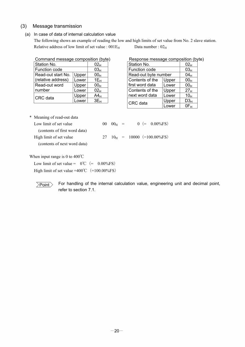
(3) Message transmission (a) In case of data of internal calculation value
The following shows an example of reading the low and high limits of set value from No. 2 slave station. Relative address of low limit of set value : 001EH Data number : 02H
Command message composition (byte) Response message composition (byte) Station No. 02H Station No. 02H Function code 03H Function code 03H
Upper 00H Read-out byte number 04H Read-out start No. (relative address) Lower 1EH Upper 00H
Upper 00H Contents of the first word data Lower 00H Read-out word
number Lower 02H Upper 27H Upper A4H
Contents of the next word data Lower 10H CRC data Lower 3EH Upper D3H
CRC data Lower 0FH * Meaning of read-out data
Low limit of set value 00 00H = 10000(=100.00%FS) (contents of first word data) High limit of set value 27 10H = 10000(=100.00%FS) (contents of next word data)
When input range is 0 to 400℃
Low limit of set value =400℃(=100.00%FS) High limit of set value =400℃(=100.00%FS)
Point For handling of the internal calculation value, engineering unit and decimal point, refer to section 7.1.
-21-
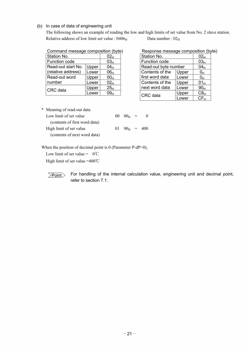
(b) In case of data of engineering unit The following shows an example of reading the low and high limits of set value from No. 2 slave station. Relative address of low limit set value : 0406H Data number : 02H
Command message composition (byte) Response message composition (byte) Station No. 02H Station No. 02H Function code 03H Function code 03H
Upper 04H Read-out byte number 04H Read-out start No. (relative address) Lower 06H Upper 0H
Upper 00H Contents of the first word data Lower 0H Read-out word
number Lower 02H Upper 01H Upper 25H
Contents of the next word data Lower 90H CRC data Lower 09H Upper C8H
CRC data Lower CFH * Meaning of read-out data
Low limit of set value 00 00H = 100 (contents of first word data) High limit of set value 01 90H = 400 (contents of next word data)
When the position of decimal point is 0 (Parameter P-dP=0),
Low limit of set value =400℃ High limit of set value =400℃
Point For handling of the internal calculation value, engineering unit and decimal point, refer to section 7.1.
-22-
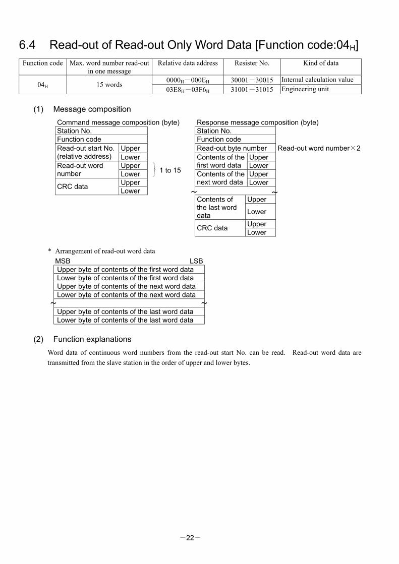
6.4 Read-out of Read-out Only Word Data [Function code:04H] Function code Max. word number read-out
in one message Relative data address Resister No. Kind of data
0000H-000EH 30001-30015 Internal calculation value 04H 15 words
03E8H-03F6H 31001-31015 Engineering unit
(1) Message composition Command message composition (byte) Response message composition (byte) Station No. Station No. Function code Function code
Upper Read-out byte number Read-out word number×2 Read-out start No. (relative address) Lower Upper
Upper Contents of the first word data Lower Read-out word
number Lower
1 to 15 Upper
Upper Contents of the next word data Lower CRC data Lower
Upper Contents of the last word data Lower
Upper
CRC data Lower * Arrangement of read-out word data
MSB LSB Upper byte of contents of the first word data Lower byte of contents of the first word data Upper byte of contents of the next word data Lower byte of contents of the next word data Upper byte of contents of the last word data Lower byte of contents of the last word data
(2) Function explanations
Word data of continuous word numbers from the read-out start No. can be read. Read-out word data are transmitted from the slave station in the order of upper and lower bytes.
~ ~
~ ~

-23-
(3) Message transmission (a) In case of data of internal calculation value
The following shows an example of reading-out the PV from No. 1 slave station. Relative address of PV:0000H Data number:01H
Command message composition (byte) Response message composition (byte) Station No. 01H Station No. 01H Function code 04H Function code 04H
Upper 00H Read-out byte number 02H Read-out start No. (relative address) Lower 00H Upper 03H
Upper 00H Contents of the first word data Lower 46H Read-out word
number Lower 01H Upper 38H Upper 31H CRC data Lower 32H CRC data Lower CAH
* Meaning of read-out data
Contents of the first word data 03 46H = 838(=8.38%FS)
When input range is 0-400℃, PV=33.5℃(=8.38%FS×400)
Input range
(b) In case of data of engineering unit The following shows an example of reading-out the PV value from No. 1 slave station. Relative address of PV value:03E8H Data number:01H
Command message composition (byte) Response message composition (byte) Station No. 01H Station No. 01H Function code 04H Function code 04H
Upper 03H Read-out byte number 02H Read-out start No. (relative address) Lower E8H Upper 01H
Upper 00H Contents of the first word data Lower 4FH Read-out word
number Lower 01H Upper 38H Upper B1H CRC data Lower 32H CRC data Lower BAH
* Meaning of read-out data
Contents of the first word data 01 4FH = 335
When the position of decimal point is 1 (Parameter P-dP=1), PV=33.5℃(=33.5)
Point For handling of the internal calculation value, engineering unit and decimal point, refer to section 7.1.
-24-
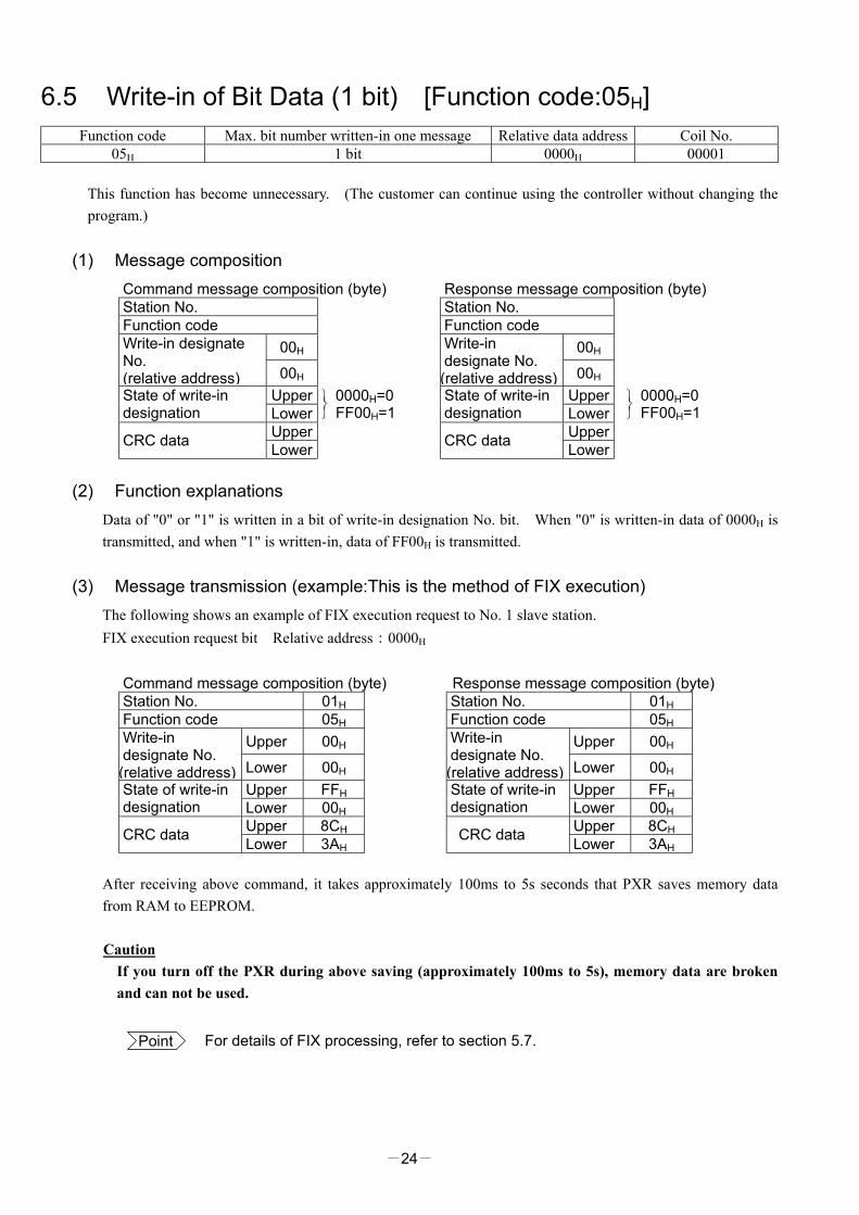
6.5 Write-in of Bit Data (1 bit) [Function code:05H] Function code Max. bit number written-in one message Relative data address Coil No.
05H 1 bit 0000H 00001 This function has become unnecessary. (The customer can continue using the controller without changing the program.)
(1) Message composition Command message composition (byte) Response message composition (byte) Station No. Station No. Function code Function code
00H 00H Write-in designate No. (relative address) 00H
Write-in designate No. (relative address) 00H
Upper Upper State of write-in designation Lower
0000H=0 FF00H=1 State of write-in
designation Lower 0000H=0 FF00H=1
Upper Upper CRC data Lower CRC data Lower
(2) Function explanations Data of "0" or "1" is written in a bit of write-in designation No. bit. When "0" is written-in data of 0000H is transmitted, and when "1" is written-in, data of FF00H is transmitted.
(3) Message transmission (example:This is the method of FIX execution) The following shows an example of FIX execution request to No. 1 slave station. FIX execution request bit Relative address:0000H
Command message composition (byte) Response message composition (byte) Station No. 01H Station No. 01H Function code 05H Function code 05H
Upper 00H Upper 00H Write-in designate No. (relative address) Lower 00H
Write-in designate No. (relative address) Lower 00H
Upper FFH Upper FFH State of write-in designation Lower 00H State of write-in
designation Lower 00H Upper 8CH Upper 8CH CRC data Lower 3AH CRC data Lower 3AH
After receiving above command, it takes approximately 100ms to 5s seconds that PXR saves memory data from RAM to EEPROM. Caution
If you turn off the PXR during above saving (approximately 100ms to 5s), memory data are broken and can not be used.
Point For details of FIX processing, refer to section 5.7.
-25-
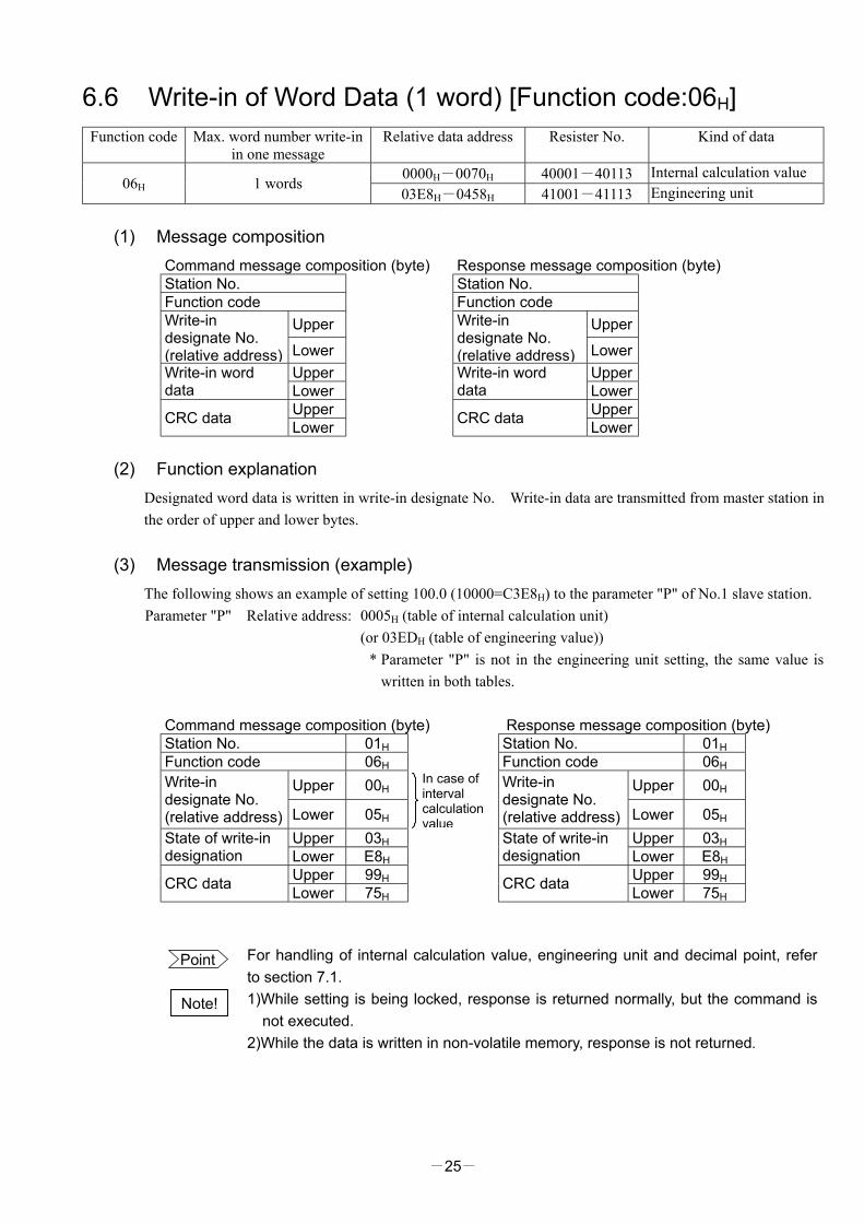
6.6 Write-in of Word Data (1 word) [Function code:06H] Function code Max. word number write-in
in one message Relative data address Resister No. Kind of data
0000H-0070H 40001-40113 Internal calculation value 06H 1 words
03E8H-0458H 41001-41113 Engineering unit
(1) Message composition Command message composition (byte) Response message composition (byte) Station No. Station No. Function code Function code
Upper Upper Write-in designate No. (relative address) Lower
Write-in designate No. (relative address) Lower
Upper Upper Write-in word data Lower Write-in word
data Lower Upper Upper CRC data Lower CRC data Lower
(2) Function explanation
Designated word data is written in write-in designate No. Write-in data are transmitted from master station in the order of upper and lower bytes.
(3) Message transmission (example) The following shows an example of setting 100.0 (10000=C3E8H) to the parameter "P" of No.1 slave station. Parameter "P" Relative address: 0005H (table of internal calculation unit)
(or 03EDH (table of engineering value)) * Parameter "P" is not in the engineering unit setting, the same value is
written in both tables.
Command message composition (byte) Response message composition (byte) Station No. 01H Station No. 01H Function code 06H Function code 06H
Upper 00H Upper 00H Write-in designate No. (relative address) Lower 05H
In case of interval calculation value
Write-in designate No. (relative address) Lower 05H
Upper 03H Upper 03H State of write-in designation Lower E8H State of write-in
designation Lower E8H Upper 99H Upper 99H CRC data Lower 75H CRC data Lower 75H
Point For handling of internal calculation value, engineering unit and decimal point, refer to section 7.1.
Note! 1)While setting is being locked, response is returned normally, but the command is
not executed. 2)While the data is written in non-volatile memory, response is not returned.

-26-
6.7 Write-in of Continuous Word Data [Function code:10H] Function code Max. word number write-in
in one message Relative data address Resister No. Kind of data
0000H-0070H 40001-40113 Internal calculation value 10H 60 words
03E8H-0458H 41001-41113 Engineering unit
(1) Message composition Command message composition (byte) Response message composition (byte) Station No. Station No. Function code Function code
Upper Upper Write-in start No. (relative address) Lower
Write-in start No. (relative address) Lower
Upper Upper Write-in word number Lower
1 to 60 Write-in word
number Lower Upper Write-in byte number
Write-in word number×2 CRC data Lower
Upper First write-in word data Lower
Upper Next write-in word data Lower
Upper Last write-in word data Lower
Upper CRC data Lower * Arrangement of write-in word data
MSB LSB Upper byte of contents of the first word data Lower byte of contents of the first word data Upper byte of contents of the next word data Lower byte of contents of the next word data Upper byte of contents of the last word data Lower byte of contents of the last word data
(2) Function explanation
Word data of continuous word number is written from write-in start address. Write-in word data are transmitted from master station in the order of upper and lower bytes.
~ ~
~ ~
-27-
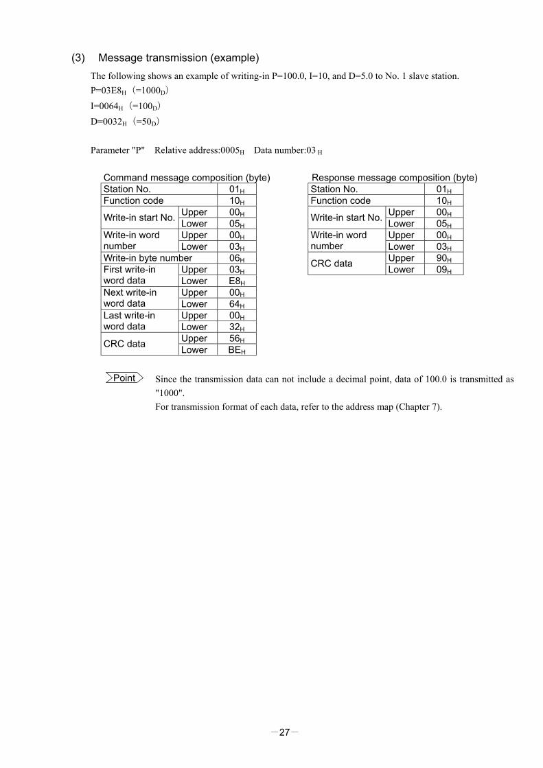
(3) Message transmission (example) The following shows an example of writing-in P=100.0, I=10, and D=5.0 to No. 1 slave station. P=03E8H(=1000D) I=0064H(=100D) D=0032H(=50D) Parameter "P" Relative address:0005H Data number:03 H
Command message composition (byte) Response message composition (byte) Station No. 01H Station No. 01H Function code 10H Function code 10H
Upper 00H Upper 00H Write-in start No. Lower 05H Write-in start No. Lower 05H Upper 00H Upper 00H Write-in word
number Lower 03H Write-in word number Lower 03H
Write-in byte number 06H Upper 90H Upper 03H CRC data Lower 09H First write-in
word data Lower E8H Upper 00H Next write-in
word data Lower 64H Upper 00H Last write-in
word data Lower 32H Upper 56H CRC data Lower BEH
Point
Since the transmission data can not include a decimal point, data of 100.0 is transmitted as "1000". For transmission format of each data, refer to the address map (Chapter 7).
-28-
7. ADDRESS MAP AND DATA FORMAT 7.1 Data Format
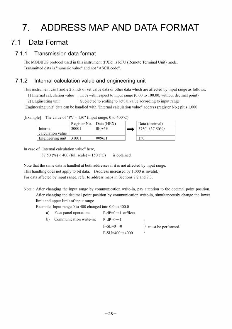
7.1.1 Transmission data format The MODBUS protocol used in this instrument (PXR) is RTU (Remote Terminal Unit) mode. Transmitted data is "numeric value" and not "ASCII code".
7.1.2 Internal calculation value and engineering unit This instrument can handle 2 kinds of set value data or other data which are affected by input range as follows.
1) Internal calculation value : In % with respect to input range (0.00 to 100.00, without decimal point) 2) Engineering unit : Subjected to scaling to actual value according to input range
"Engineering unit" data can be handled with "Internal calculation value" address (register No.) plus 1,000
[Example] The value of "PV = 150" (input range: 0 to 400°C) Register No. Data (HEX) Data (decimal) Internal calculation value
30001 0EA6H 3750(37.50%)
Engineering unit 31001 0096H 150 In case of "Internal calculation value" here,
37.50 (%) × 400 (full scale) = 150 (°C) is obtained.
Note that the same data is handled at both addresses if it is not affected by input range. This handling does not apply to bit data. (Address increased by 1,000 is invalid.) For data affected by input range, refer to address maps in Sections 7.2 and 7.3. Note : After changing the input range by communication write-in, pay attention to the decimal point position.
After changing the decimal point position by communication write-in, simultaneously change the lower limit and upper limit of input range. Example: Input range 0 to 400 changed into 0.0 to 400.0
a) Face panel operation: P-dP=0→1 suffices b) Communication write-in: P-dP=0→1 P-SL=0→0 P-SU=400→4000
must be performed.
-29-
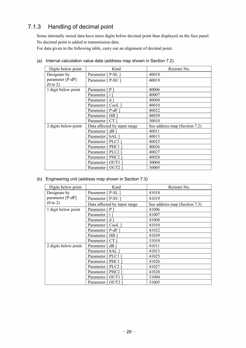
7.1.3 Handling of decimal point Some internally stored data have more digits below decimal point than displayed on the face panel. No decimal point is added to transmission data. For data given in the following table, carry out an alignment of decimal point. (a) Internal calculation value data (address map shown in Section 7.2)
Digits below point Kind Resister No. Parameter [ P-SL ] 40018 Designate by
parameter [P-dP] (0 to 2)
Parameter [ P-SU ] 40019
Parameter [ P ] 40006 Parameter [ i ] 40007 Parameter [ d ] 40008 Parameter [ CooL ] 40010 Parameter [ P-dF ] 40022 Parameter [ HB ] 40039
1 digit below point
Parameter [ CT ] 30010 Data affected by input range See address map (Section 7.2) Parameter [ dB ] 40011 Parameter [ bAL ] 40013 Parameter [ PLC1 ] 40025 Parameter [ PHC1 ] 40026 Parameter [ PLC2 ] 40027 Parameter [ PHC2 ] 40028 Parameter [ OUT1 ] 30004
2 digits below point
Parameter [ OUT2 ] 30005 (b) Engineering unit (address map shown in Section 7.3)
Digits below point Kind Resister No. Parameter [ P-SL ] 41018 Parameter [ P-SU ] 41019
Designate by parameter [P-dP] (0 to 2) Data affected by input range See address map (Section 7.3)
Parameter [ P ] 41006 Parameter [ i ] 41007 Parameter [ d ] 41008 Parameter [ CooL ] 41010 Parameter [ P-dF ] 41022 Parameter [ HB ] 41039
1 digit below point
Parameter [ CT ] 31010 Parameter [ dB ] 41011 Parameter [ bAL ] 41013 Parameter [ PLC1 ] 41025 Parameter [ PHC1 ] 41026 Parameter [ PLC2 ] 41027 Parameter [ PHC2 ] 41028 Parameter [ OUT1 ] 31004
2 digits below point
Parameter [ OUT2 ] 31005

-30-
7.1.4 Data when input is abnormal When "UUUU" or "LLLL" is displayed on the face panel on account of over-range, under-range or input open-circuit for example, PV read-out value is 105% or -5% of input range. Presence of any input abnormality via communication can be detected by:
"Register No. 30008 (or 31008): Input/main unit abnormal status"
-31-
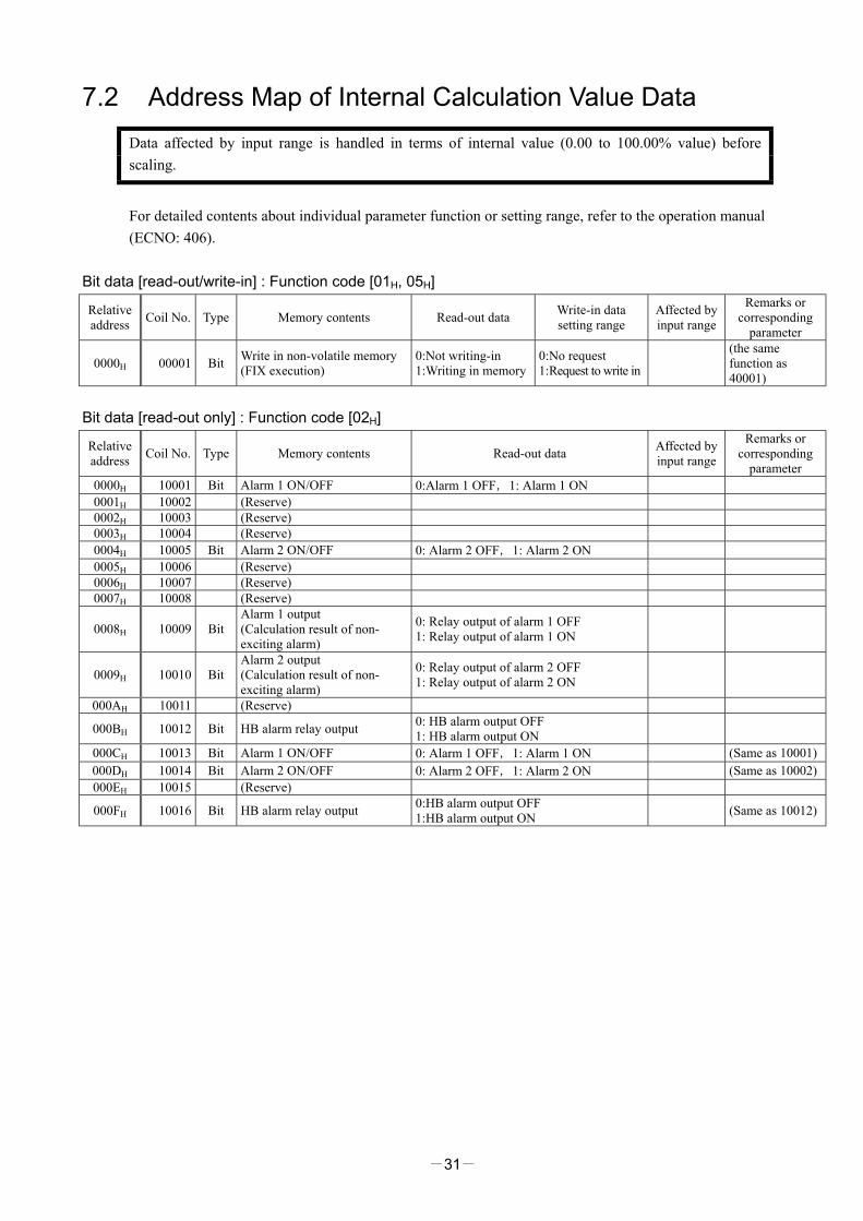
7.2 Address Map of Internal Calculation Value Data Data affected by input range is handled in terms of internal value (0.00 to 100.00% value) before scaling.
For detailed contents about individual parameter function or setting range, refer to the operation manual (ECNO: 406).
Bit data [read-out/write-in] : Function code [01H, 05H]
Relative address Coil No. Type Memory contents Read-out data Write-in data
setting range Affected by input range
Remarks or corresponding
parameter
0000H 00001 Bit Write in non-volatile memory (FIX execution)
0:Not writing-in 1:Writing in memory
0:No request 1:Request to write in
(the same function as 40001)
Bit data [read-out only] : Function code [02H]
Relative address Coil No. Type Memory contents Read-out data Affected by
input range
Remarks or corresponding
parameter 0000H 10001 Bit Alarm 1 ON/OFF 0:Alarm 1 OFF,1: Alarm 1 ON 0001H 10002 (Reserve) 0002H 10003 (Reserve) 0003H 10004 (Reserve) 0004H 10005 Bit Alarm 2 ON/OFF 0: Alarm 2 OFF,1: Alarm 2 ON 0005H 10006 (Reserve) 0006H 10007 (Reserve) 0007H 10008 (Reserve)
0008H 10009 Bit Alarm 1 output (Calculation result of non-exciting alarm)
0: Relay output of alarm 1 OFF 1: Relay output of alarm 1 ON
0009H 10010 Bit Alarm 2 output (Calculation result of non-exciting alarm)
0: Relay output of alarm 2 OFF 1: Relay output of alarm 2 ON
000AH 10011 (Reserve)
000BH 10012 Bit HB alarm relay output 0: HB alarm output OFF 1: HB alarm output ON
000CH 10013 Bit Alarm 1 ON/OFF 0: Alarm 1 OFF,1: Alarm 1 ON (Same as 10001) 000DH 10014 Bit Alarm 2 ON/OFF 0: Alarm 2 OFF,1: Alarm 2 ON (Same as 10002) 000EH 10015 (Reserve)
000FH 10016 Bit HB alarm relay output 0:HB alarm output OFF 1:HB alarm output ON (Same as 10012)

-32-
Word data [read-out/write-in] : Function code [03H, 06H, 10H]
Relative address
Resister No. Type Memory contents Read-out data Write-in data
setting range Affected by input range
Remarks or corresponding
parameter
0000H 40001 Word Non-volatile memory write-in 0: Not writing-in 1: Writing in memory
0:No request 1:Request to write in
(Same function as 00001)
0001H 40002 Word PID/FUZZY/SELF selection 0:PID control 1:FUZZYcontrol 2:SELF tuning control
CTrL * Inhibit change
while controlling
0002H 40003 Word SV value set on face panel 0 to 10000 (within 0.00 to 100.00% FS within set value limits)
*
0003H 40004 Word Control RUN/standby 0: Invalidate standby (RUN) 1:Validate standby STby
0004H 40005 Word Auto tuning command
0: Auto tuning disabled
1: While executing standard type AT executed
2: While executing low PV type AT executed
0: Disable auto tuning
1: Request execution of standard type
2: Request execution of low PV type AT
AT
0005H 40006 Word P 0 to 9999(0.0 to 999.9%) P 0006H 40007 Word I 0 to 32000(0 to 3200.0 sec) i 0007H 40008 Word D 0 to 9999(0.0 to 999.9 sec) D
0008H 40009 Word Hysteresis range at two-position control 0 to 5000(0.00 to 50.00%FS) * HyS
0009H 40010 Word COOL 0 to 1000(0.0 to 100.0) CooL 000AH 40011 Word Dead band -5000 to 5000(-50.00 to +50.00) db 000BH 40012 Word Anti-reset windup 0 to 10000(0.00 to 100.00%) * Ar
000CH 40013 Word Output convergence value -10000 to 10000 (-100.00 to 100.00%) bAL
000DH 40014 Word PV shift -1000 to 1000(-10.00 to 10.00%FS) * PVOF 000EH 40015 Word SV offset -5000 to 5000(-50.00 to 50.00%FS) * SVOF 000FH 40016 Word Input type code 0 to 16 P-n2 0010H 40017 Word Temperature unit 0:℃ 1:°F P-F 0011H 40018 Word Input scale lower limit -1999 to 9999 P-SL 0012H 40019 Word Input scale upper limit -1999 to 9999 P-SU 0013H 40020 Word Decimal point place 0 to 2 P-dP 0014H 40021 (Do not use) 0015H 40022 Word Input filter time constant 0 to 9000(0.0 to 900.0 sec) P-dF
0016H 40023 Word RCJ yes/no
0: Disable RCJ compensation (do not perform reference cold junction compensation)
1: Enable RCJ compensation (perform reference cold junction compensation)
rCJ
0017H 40024 Word MV limit kind 0 to 15 PCUT 0018H 40025 Word Output 1 lower limit -300 to 10300(-3.00 to 103.00%) PLC1 0019H 40026 Word Output 1 upper limit -300 to 10300(-3.00 to 103.00%) PHC1 001AH 40027 Word Output 2 lower limit -300 to 10300(-3.00 to 103.00%) PLC2 001BH 40028 Word Output 2 upper limit -300 to 10300(-3.00 to 103.00%) PHC2 001CH 40029 (Do not use) 001DH 40030 (Do not use) 001EH 40031 Word Set value (SV) lower limit 0 to 10000(0.00 to 100.00%FS) * SV-L 001FH 40032 Word Set value (SV) upper limit 0 to 10000(0.00 to 100.00%FS) * SV-H 0020H 40033 (Do not use) 0021H 40034 (Do not use) 0022H 40035 (Do not use) 0023H 40036 (Do not use) 0024H 40037 (Do not use) 0025H 40038 (Do not use) 0026H 40039 Word Heater burnout alarm set value 0 to 500(0.0 to 50.0A) Hb 0027H 40040 Word Setting lock 0 to 5 LoC

-33-
Relative address
Resister No. Type Memory contents Read-out data Write-in data
setting range Affected by input range
Remarks or corresponding
parameter 0028H 40041 Word Alarm 1 type 0 to 34 ALM1 0029H 40042 Word Alarm 2 type 0 to 34 ALM2 002AH 40043 (Do not use)
002BH 40044 Word Alarm 1 set value or alarm 1 lower limit set value * AL1 or A1-L
002CH 40045 Word Alarm 2 set value or alarm 2 lower limit set value
For absolute value alarm 0 to 10000(0.00 to 100.00%FS)
For deviation alarm -10000 to 10000 (-100.00 to 100.00%FS)
* AL2 or A2-L
002DH 40046 (Do not use)
002EH 40047 Word Alarm 1 upper limit set value * A1-H
002FH 40048 Word Alarm 2 upper limit set value
For absolute value alarm 0 to 10000(0.00 to 100.00%FS)
For deviation alarm -10000 to 10000 (-100.00 to 100.00%FS)
* A2-H
0030H 40049 (Do not use) 0031H 40050 Word Alarm 1 hysteresis 0 to 5000(0.00 to 50.00%FS) * A1hy 0032H 40051 Word Alarm 2 hysteresis 0 to 5000(0.00 to 50.00%FS) * A2hy 0033H 40052 (Do not use) 0034H 40053 Word Alarm 1 ON-delay set value 0 to 9999(0 to 9999 sec) dLy1 0035H 40054 Word Alarm 2 ON-delay set value 0 to 9999(0 to 9999 sec) dLy2 0036H 40055 (Do not use) 0037H 40056 (Do not use) 0038H 40057 Word Ramp/soak No. 1 target value * Sv-1 0039H 40058 Word Ramp/soak No. 2 target value * Sv-2 003AH 40059 Word Ramp/soak No. 3 target value * Sv-3 003BH 40060 Word Ramp/soak No. 4 target value * Sv-4 003CH 40061 Word Ramp/soak No. 5 target value * Sv-5 003DH 40062 Word Ramp/soak No. 6 target value * Sv-6 003EH 40063 Word Ramp/soak No. 7 target value * Sv-7 003FH 40064 Word Ramp/soak No. 8 target value
0 to 10000 (0.00 to 100.00%FS, within set value limit)
* Sv-8 0040H 40065 Word Ramp/soak No. 1 ramp time TM1r 0041H 40066 Word Ramp/soak No. 1 soak time TM1S 0042H 40067 Word Ramp/soak No. 2 ramp time TM2r 0043H 40068 Word Ramp/soak No. 2 soak time TM2S 0044H 40069 Word Ramp/soak No. 3 ramp time TM3r 0045H 40070 Word Ramp/soak No. 3 soak time TM3S 0046H 40071 Word Ramp/soak No. 4 ramp time TM4r 0047H 40072 Word Ramp/soak No. 4 soak time TM4S 0048H 40073 Word Ramp/soak No. 5 ramp time TM5r 0049H 40074 Word Ramp/soak No. 5 soak time TM5S 004AH 40075 Word Ramp/soak No. 6 ramp time TM6r 004BH 40076 Word Ramp/soak No. 6 soak time TM6S 004CH 40077 Word Ramp/soak No. 7 ramp time TM7r 004DH 40078 Word Ramp/soak No. 7 soak time TM7S 004EH 40079 Word Ramp/soak No. 8 ramp time TM8r 004FH 40080 Word Ramp/soak No. 8 soak time
0 to 5999(0 to 5999 min) * With main unit parameter,
Hour Minute
is displayed and set. Therefore, correspondence occurs as: 3601:Data via communication ∥ 6001:Display/setting on main unit
TM8S 0050H 40081 Word Ramp/soak mode 0 to 15 MOD
0051H 40082 Word Ramp/soak command
0: oFF Ramp/soak stopped
1: rUn Ramp/soak operated
2: HLd Ramp/soak halted
3: End Ramp/soak ended
0:oFF Stop ramp/soak
1:rUn Start ramp/soak
2:HLd Halt ramp/soak
3: End ラ ン プ
ソーク終了
ProG

-34-
Note
Relative address Resister
No. Type Memory contents Read-out data Write-in data setting range
Affected by input range
Remarks or corresponding
parameter
0052H 40083 Word Ramp/soak pattern selection
0: Execute No. 1 to 4 ramp/soak(PTn=1)
1: Execute No. 5 to 8 ramp/soak(PTn=2)
2: Execute No. 1 to 8 ramp/soak(PTn=3)
PTn
0053H 40084 (Do not use) 0054H 40085 Word PV stable range 0 to 10000(0.00 to 100.00%FS) * SLFb 0055H 40086 (Do not use)
0056H 40087 Word Communication DI action request *② (refer to section 7.4.)
0057H 40088 Word Control action type code 0 to 19 P-n1
0058H 40089 Word Output proportional cycle (output 1)
0: Current output type 1 to 150(1 to 150 sec):
Relay, SSR drive output type TC
0059H 40090 Word Output proportional cycle (output 2) 1 to 150(1 to 150 sec) TC2
005AH 40091 (Do not use) 005BH 40092 Word Alarm 1 option function 0 to 7(binary data 000B to 111B) A1op 005CH 40093 Word Alarm 2 option function 0 to 7(binary data 000B to 111B) A2op 005DH 40094 (Do not use) 005EH 40095 Word DI1 action setting 0 to 12 di-1 005FH 40096 (Do not use)
0060H 40097 Word Hysteresis mode setting 0: off (main unit parameter setting) 1: on (main unit parameter setting) ONOF
0061H 40098 Word (Do not use)
0062H 40099 Word User zero adjustment -5000 to 5000 (-50.00 to 50.00%FS) * ADJ0
0063H 40100 Word User span adjustment -5000 to 5000 (-50.00 to 50.00%FS) * ADJS
0064H 40101 Word DSP1 (parameter mask designation) 0 to 255 dSP1
0065H 40102 Word DSP2 (parameter mask designation) 0 to 255 dSP2
0066H 40103 Word DSP3 (parameter mask designation) 0 to 255 dSP3
0067H 40104 Word DSP4 (parameter mask designation) 0 to 255 dSP4
0068H 40105 Word DSP5 (parameter mask designation) 0 to 255 dSP5
0069H 40106 Word DSP6 (parameter mask designation) 0 to 255 dSP6
006AH 40107 Word DSP7 (parameter mask designation) 0 to 255 dSP7
006BH 40108 Word DSP8 (parameter mask designation) 0 to 255 dSP8
006CH 40109 Word DSP9 (parameter mask designation) 0 to 255 dSP9
006DH 40110 Word DSP10 (parameter mask designation) 0 to 255 dSP10
006EH 40111 Word DSP11 (parameter mask designation) 0 to 255 dSP11
006FH 40112 Word DSP12 (parameter mask designation) 0 to 255 dSP12
0070H 40113 Word DSP13 (parameter mask designation) 0 to 255 dSP13
Note) Read-out/write-in data from Resister No. 40083 (ramp/soak pattern selection) correspond to parameter “PTn” to be displayed as shown below:
Read-out/write-in data Parameter PTn Contents 0 1 1 to 4 ramp/soak executed 1 2 5 to 8 ramp/soak executed 2 3 1 to 8 ramp/soak executed
-35-
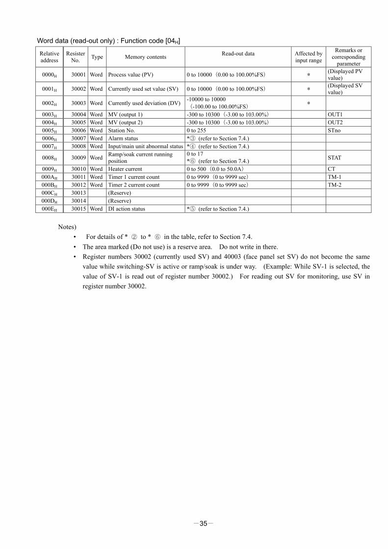
Word data (read-out only) : Function code [04H]
Relative address
Resister No. Type Memory contents Read-out data
Affected by input range
Remarks or corresponding
parameter
0000H 30001 Word Process value (PV) 0 to 10000(0.00 to 100.00%FS) * (Displayed PV value)
0001H 30002 Word Currently used set value (SV) 0 to 10000(0.00 to 100.00%FS) * (Displayed SV value)
0002H 30003 Word Currently used deviation (DV) -10000 to 10000 (-100.00 to 100.00%FS) *
0003H 30004 Word MV (output 1) -300 to 10300(-3.00 to 103.00%) OUT1 0004H 30005 Word MV (output 2) -300 to 10300(-3.00 to 103.00%) OUT2 0005H 30006 Word Station No. 0 to 255 STno 0006H 30007 Word Alarm status *③ (refer to Section 7.4.) 0007H 30008 Word Input/main unit abnormal status *④ (refer to Section 7.4.)
0008H 30009 Word Ramp/soak current running position
0 to 17 *⑥ (refer to Section 7.4.) STAT
0009H 30010 Word Heater current 0 to 500(0.0 to 50.0A) CT 000AH 30011 Word Timer 1 current count 0 to 9999(0 to 9999 sec) TM-1 000BH 30012 Word Timer 2 current count 0 to 9999(0 to 9999 sec) TM-2 000CH 30013 (Reserve) 000DH 30014 (Reserve) 000EH 30015 Word DI action status *⑤ (refer to Section 7.4.)
Notes) • For details of * ② to * ⑥ in the table, refer to Section 7.4. • The area marked (Do not use) is a reserve area. Do not write in there. • Register numbers 30002 (currently used SV) and 40003 (face panel set SV) do not become the same
value while switching-SV is active or ramp/soak is under way. (Example: While SV-1 is selected, the value of SV-1 is read out of register number 30002.) For reading out SV for monitoring, use SV in register number 30002.
-36-
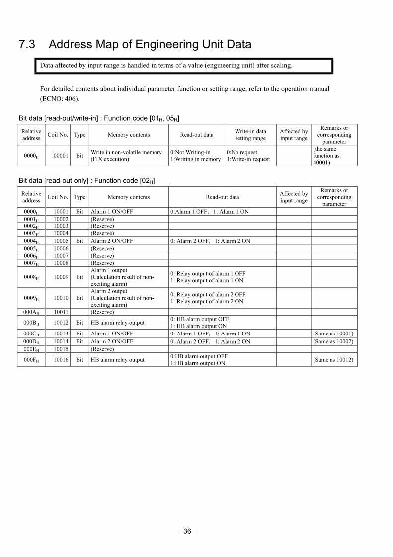
7.3 Address Map of Engineering Unit Data Data affected by input range is handled in terms of a value (engineering unit) after scaling.
For detailed contents about individual parameter function or setting range, refer to the operation manual (ECNO: 406).
Bit data [read-out/write-in] : Function code [01H, 05H]
Relative address Coil No. Type Memory contents Read-out data Write-in data
setting range Affected by input range
Remarks or corresponding
parameter
0000H 00001 Bit Write in non-volatile memory (FIX execution)
0:Not Writing-in 1:Writing in memory
0:No request 1:Write-in request
(the same function as 40001)
Bit data [read-out only] : Function code [02H]
Relative address Coil No. Type Memory contents Read-out data Affected by
input range
Remarks or corresponding
parameter 0000H 10001 Bit Alarm 1 ON/OFF 0:Alarm 1 OFF,1: Alarm 1 ON 0001H 10002 (Reserve) 0002H 10003 (Reserve) 0003H 10004 (Reserve) 0004H 10005 Bit Alarm 2 ON/OFF 0: Alarm 2 OFF,1: Alarm 2 ON 0005H 10006 (Reserve) 0006H 10007 (Reserve) 0007H 10008 (Reserve)
0008H 10009 Bit Alarm 1 output (Calculation result of non-exciting alarm)
0: Relay output of alarm 1 OFF 1: Relay output of alarm 1 ON
0009H 10010 Bit Alarm 2 output (Calculation result of non-exciting alarm)
0: Relay output of alarm 2 OFF 1: Relay output of alarm 2 ON
000AH 10011 (Reserve)
000BH 10012 Bit HB alarm relay output 0: HB alarm output OFF 1: HB alarm output ON
000CH 10013 Bit Alarm 1 ON/OFF 0: Alarm 1 OFF,1: Alarm 1 ON (Same as 10001) 000DH 10014 Bit Alarm 2 ON/OFF 0: Alarm 2 OFF,1: Alarm 2 ON (Same as 10002) 000EH 10015 (Reserve)
000FH 10016 Bit HB alarm relay output 0:HB alarm output OFF 1:HB alarm output ON (Same as 10012)

-37-
Word data [read-out/write-in]: Function code [03H, 06H, 10H] Relative address
Resister No. Type Memory contents Read-out data Write-in data
setting range Affected by input range
Remarks or corresponding
parameter
03E8H 41001 Word Non-volatile memory write-in (FIX execution)
0: Not writing in 1: Write in memory
0:No request 1:Request to write in
(Same function as 00001)
03E9 H 41002 Word PID/FUZZY/SELF selection 0:PID control 1:FUZZYcontrol 2:SELF tuning control
CTrL * Inhibit change
while controlling
03EA H 41003 Word SV value controlled on face panel -1999 to 9999 (within set value limits) *
03EB H 41004 Word Control RUN/standby 0: Invalidate standby (RUN) 1:Validate standby STby
03EC H 41005 Word Auto tuning command
0: Auto tuning disabled
1: While executing standard type AT executed
2: While executing low PV type AT executed
0: Disable auto tuning
1: Request execution of standard type
2: Request execution of low PV type AT
AT
03ED H 41006 Word P 0 to 9999(0.0 to 999.9%) P 03EE H 41007 Word I 0 to 32000(0 to 3200.0 sec) i 03EF H 41008 Word D 0 to 9999(0.0 to 999.9 sec) D
03F0 H 41009 Word Hysteresis range at two-position control 0 to 9999 (0 to 50% value of input scale) * HyS
03F1H 41010 Word COOL 0 to 1000(0.0 to 100.0) CooL
03F2H 41011 Word Dead band -5000 to 5000 (-50.00 to +50.00%) db
03F3H 41012 Word Anti-reset windup -1999 to 9999 (0 to 100% value of input scale) * Ar
03F4H 41013 Word Output convergence value -10000 to 10000 (-100.00 to 100.00%) bAL
03F5H 41014 Word PV shift -1999 to 9999 (-10 to 10% value of input scale) * PVOF
03F6H 41015 Word SV offset -1999 to 9999 (-50 to 50% value of input scale) * SVOF
03F7H 41016 Word Input type code 0 to 16 P-n2 03F8H 41017 Word Temperature unit 0:℃ 1:°F P-F 03F9H 41018 Word Input scale lower limit -1999 to 9999 P-SL 03FAH 41019 Word Input scale upper limit -1999 to 9999 P-SU 03FBH 41020 Word Decimal point place 0 to 2 P-dP 03FCH 41021 (Do not use) 03FDH 41022 Word Input filter time constant 0 to 9000(0.0 to 900.0 sec) P-dF
03FEH 41023 Word RCJ yes/no
0: Disable RCJ compensation (do not perform reference cold junction compensation)
1: Enable RCJ compensation (perform reference cold junction compensation)
rCJ
03FFH 41024 Word MV limit kind 0 to 15 PCUT 0400H 41025 Word Output 1 lower limit -300 to 10300(-3.00 to 103.00%) PLC1 0401H 41026 Word Output 1 upper limit -300 to 10300(-3.00 to 103.00%) PHC1 0402H 41027 Word Output 2 lower limit -300 to 10300(-3.00 to 103.00%) PLC2 0403H 41028 Word Output 2 upper limit -300 to 10300(-3.00 to 103.00%) PHC2 0404H 41029 (Do not use) 0405H 41030 (Do not use) 0406H 41031 Word Set value (SV) lower limit -1999 to 9999(within input scale) * SV-L 0407H 41032 Word Set value (SV) upper limit -1999 to 9999(within input scale) * SV-H 0408H 41033 (Do not use) 0409H 41034 (Do not use) 040AH 41035 (Do not use) 040BH 41036 (Do not use) 040CH 41037 (Do not use) 040DH 41038 (Do not use) 040EH 41039 Word Heater burnout alarm set value 0 to 500(0.0 to 50.0A) Hb

-38-
Relative address
Resister No. Type Memory contents Read-out data Write-in data
setting range Affected by input range
Remarks or corresponding
parameter 040FH 41040 Word Setting lock 0 to 5 LoC 0410H 41041 Word Alarm 1 type 0 to 34 ALM1 0411H 41042 Word Alarm 2 type 0 to 34 ALM2 0412H 41043 (Do not use)
0413H 41044 Word Alarm 1 set value or alarm 1 lower limit set value * AL1 or A1-L
0414H 41045 Word Alarm 2 set value or alarm 2 lower limit set value
-1999 to 9999 For absolute value alarm:
0 to 100% value of input scale For deviation alarm:
–100 to 100% value of input scale * AL2 or A2-L
0415H 41046 (Do not use)
0416H 41047 Word Alarm 1 upper limit set value * A1-H
0417H 41048 Word Alarm 2 upper limit set value
-1999 to 9999 For absolute value alarm:
0 to 100% value of input scale For deviation alarm:
–100 to 100% value of input scale * A2-H
0418H 41049 (Do not use)
0419H 41050 Word Alarm 1 hysteresis 0 to 9999 (0 to 50% value of input scale) * A1hy
041AH 41051 Word Alarm 2 hysteresis 0 to 9999 (0 to 50% value of input scale) * A2hy
041BH 41052 (Do not use) 041CH 41053 Word Alarm 1 ON-delay set value 0 to 9999(0 to 9999 sec) dLy1 041DH 41054 Word Alarm 2 ON-delay set value 0 to 9999(0 to 9999 sec) dLy2 041EH 41055 (Do not use) 041FH 41056 (Do not use) 0420H 41057 Word Ramp/soak No. 1 target value * Sv-1 0421H 41058 Word Ramp/soak No. 2 target value * Sv-2 0422H 41059 Word Ramp/soak No. 3 target value * Sv-3 0423H 41060 Word Ramp/soak No. 4 target value * Sv-4 0424H 41061 Word Ramp/soak No. 5 target value * Sv-5 0425H 41062 Word Ramp/soak No. 6 target value * Sv-6 0426H 41063 Word Ramp/soak No. 7 target value * Sv-7 0427H 41064 Word Ramp/soak No. 8 target value
-1999 to 9999 (within set value limit)
* Sv-8 0428H 41065 Word Ramp/soak No. 1 ramp time TM1r 0429H 41066 Word Ramp/soak No. 1 soak time TM1S 042AH 41067 Word Ramp/soak No. 2 ramp time TM2r 042BH 41068 Word Ramp/soak No. 2 soak time TM2S 042CH 41069 Word Ramp/soak No. 3 ramp time TM3r 042DH 41070 Word Ramp/soak No. 3 soak time TM3S 042EH 41071 Word Ramp/soak No. 4 ramp time TM4r 042FH 41072 Word Ramp/soak No. 4 soak time TM4S 0430H 41073 Word Ramp/soak No. 5 ramp time TM5r 0431H 41074 Word Ramp/soak No. 5 soak time TM5S 0432H 41075 Word Ramp/soak No. 6 ramp time TM6r 0433H 41076 Word Ramp/soak No. 6 soak time TM6S 0434H 41077 Word Ramp/soak No. 7 ramp time TM7r 0435H 41078 Word Ramp/soak No. 7 soak time TM7S 0436H 41079 Word Ramp/soak No. 8 ramp time TM8r 0437H 41080 Word Ramp/soak No. 8 soak time
0 to 5999(0 to 5999 min) * With main unit parameter,
Hour Minute
is displayed and set. Therefore, correspondence occurs as: 3601:Data via communication ∥ 6001:Display/setting on main unit
TM8S 0438H 41081 Word Ramp/soak mode 0 to 15 MOD
0439H 41082 Word Ramp/soak command
0: oFF Ramp/soak stopped
1: rUn Ramp/soak operated
2: HLd Ramp/soak halted
3: End Ramp/soak ended
0:oFF Stop ramp/soak
1:rUn Start ramp/soak
2:HLd Halt ramp/soak
3: End ラ ン プ
ソーク終了
ProG

-39-
Note
Relative address
Resister No. Type Memory contents Read-out data Write-in data
setting range Affected by input range
Remarks or corresponding
parameter
043AH 41083 Word Ramp/soak pattern selection 0: Execute No. 1 to 4 ramp/soak 1: Execute No. 5 to 8 ramp/soak 2: Execute No. 1 to 8 ramp/soak
PTn
043BH 41084 (Do not use) 043CH 41085 Word PV stable range -1999 to 9999 (Within input scale) * SLFb 043DH 41086 (Do not use)
043EH 41087 Word Communication DI action request *② (refer to section 7.4.)
043FH 41088 Word Control action type code 0 to 19 P-n1
0440H 41089 Word Output proportional cycle (output 1)
0: Current output type 1 to 150(1 to 150 sec):
Relay, SSR drive output type TC
0441H 41090 Word Output proportional cycle (output 2) 1 to 150(1 to 150 sec) TC2
0442H 41091 (Do not use) 0443H 41092 Word Alarm 1 option function 0 to 7(binary data 000B to 111B) A1op 0444H 41093 Word Alarm 2 option function 0 to 7(binary data 000B to 111B) A2op 0445H 41094 (Do not use) 0446H 41095 Word DI1 action setting 0 to 12 di-1 0447H 41096 (Do not use)
0448H 41097 Word Hysteresis mode setting 0: off (main unit parameter setting) 1: on (main unit parameter setting) ONOF
0449H 41098 Word (Do not use)
044AH 41099 Word User zero adjustment -1999 to 9999 (-50 to 50% value of input scale) * ADJ0
044BH 41100 Word User span adjustment -1999 to 9999 (-50 to 50% value of input scale) * ADJS
044CH 41101 Word DSP1 (parameter mask designation) 0 to 255 dSP1
044DH 41102 Word DSP2 (parameter mask designation) 0 to 255 dSP2
044EH 41103 Word DSP3 (parameter mask designation) 0 to 255 dSP3
044FH 41104 Word DSP4 (parameter mask designation) 0 to 255 dSP4
0450H 41105 Word DSP5 (parameter mask designation) 0 to 255 dSP5
0451H 41106 Word DSP6 (parameter mask designation) 0 to 255 dSP6
0452H 41107 Word DSP7 (parameter mask designation) 0 to 255 dSP7
0453H 41108 Word DSP8 (parameter mask designation) 0 to 255 dSP8
0454H 41109 Word DSP9 (parameter mask designation) 0 to 255 dSP9
0455H 41110 Word DSP10 (parameter mask designation) 0 to 255 dSP10
0456H 41111 Word DSP11 (parameter mask designation) 0 to 255 dSP11
0457H 41112 Word DSP12 (parameter mask designation) 0 to 255 dSP12
0458H 41113 Word DSP13 (parameter mask designation) 0 to 255 dSP13
Note) Read-out/write-in data from Resister No. 41083 (ramp/soak pattern selection) correspond to parameter “PTn” to be displayed as shown below:
Read-out/write-in data Parameter PTn Contents 0 1 1 to 4 ramp/soak executed 1 2 5 to 8 ramp/soak executed 2 3 1 to 8 ramp/soak executed

-40-
Word data (read-out only) : Function code [04H]
Relative address
Resister No. Type Memory contents Read-out data
Affected by input range
Remarks or corresponding
parameter
03E8H 31001 Word Process value (PV) -1999 to 9999 (within input scale) * (Displayed PV value)
03E9H 31002 Word Currently used set value (SV) -1999 to 9999 (within set value limit) * (Dsiplayed SV value)
03EAH 31003 Word Currently used deviation (DV) -1999 to 9999 (-100 to 100% value of input scale) *
03EBH 31004 Word MV (output 1) -300 to 10300(-3.00 to 103.00%) OUT1 03ECH 31005 Word MV (output 2) -300 to 10300(-3.00 to 103.00%) OUT2 03EDH 31006 Word Station No. 0 to 255 STno 03EEH 31007 Word Alarm status *③ (refer to Section 7.4.) 03EFH 31008 Word Input/main unit abnormal status *④ (refer to Section 7.4.)
03F0H 31009 Word Ramp/soak current running position
0 to 17 *⑥ (refer to Section 7.4.) STAT
03F1H 31010 Word Heater current 0 to 500(0.0 to 50.0A) CT 03F2H 31011 Word Timer 1 current count 0 to 9999(0 to 9999 sec) TM-1 03F3H 31012 Word Timer 2 current count 0 to 9999(0 to 9999 sec) TM-2 03F4H 31013 (Reserve) 03F5H 31014 (Reserve) 03F6H 31015 Word DI action status *⑤ (refer to Section 7.4.)
Notes) • For details of * ② to * ⑥ in the table, refer to Section 7.4. • The area marked (Do not use) is a reserve area. Do not write in there. • Register numbers 31002 (currently used SV) and 41003 (face panel set SV) do not become the same
value while switching-SV is active or ramp/soak is under way. (Example: While SV-1 is selected, the value of SV-1 is read out of register number 31002.) For reading out SV for monitoring, use SV in register number 31002.
-41-
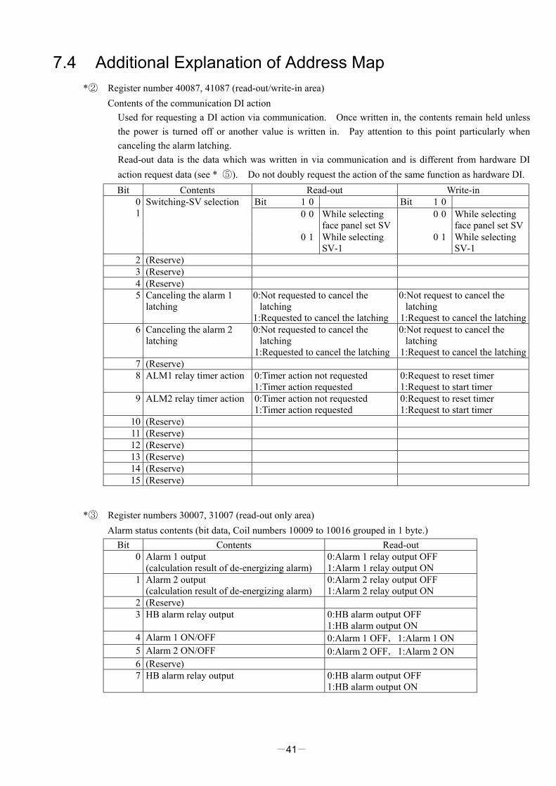
7.4 Additional Explanation of Address Map *② Register number 40087, 41087 (read-out/write-in area)
Contents of the communication DI action Used for requesting a DI action via communication. Once written in, the contents remain held unless the power is turned off or another value is written in. Pay attention to this point particularly when canceling the alarm latching. Read-out data is the data which was written in via communication and is different from hardware DI action request data (see * ⑤). Do not doubly request the action of the same function as hardware DI. Bit Contents Read-out Write-in
Bit 1 0 Bit 1 0 0 0 While selecting
face panel set SV 0 0 While selecting
face panel set SV
0 1
Switching-SV selection
0 1 While selecting SV-1
0 1 While selecting SV-1
2 (Reserve) 3 (Reserve) 4 (Reserve) 5 Canceling the alarm 1
latching 0:Not requested to cancel the
latching 1:Requested to cancel the latching
0:Not request to cancel the latching
1:Request to cancel the latching 6 Canceling the alarm 2
latching 0:Not requested to cancel the
latching 1:Requested to cancel the latching
0:Not request to cancel the latching
1:Request to cancel the latching 7 (Reserve) 8 ALM1 relay timer action 0:Timer action not requested
1:Timer action requested 0:Request to reset timer 1:Request to start timer
9 ALM2 relay timer action 0:Timer action not requested 1:Timer action requested
0:Request to reset timer 1:Request to start timer
10 (Reserve) 11 (Reserve) 12 (Reserve) 13 (Reserve) 14 (Reserve) 15 (Reserve)
*③ Register numbers 30007, 31007 (read-out only area)
Alarm status contents (bit data, Coil numbers 10009 to 10016 grouped in 1 byte.) Bit Contents Read-out
0 Alarm 1 output (calculation result of de-energizing alarm)
0:Alarm 1 relay output OFF 1:Alarm 1 relay output ON
1 Alarm 2 output (calculation result of de-energizing alarm)
0:Alarm 2 relay output OFF 1:Alarm 2 relay output ON
2 (Reserve) 3 HB alarm relay output 0:HB alarm output OFF
1:HB alarm output ON 4 Alarm 1 ON/OFF 0:Alarm 1 OFF,1:Alarm 1 ON 5 Alarm 2 ON/OFF 0:Alarm 2 OFF,1:Alarm 2 ON 6 (Reserve) 7 HB alarm relay output 0:HB alarm output OFF
1:HB alarm output ON
-42-
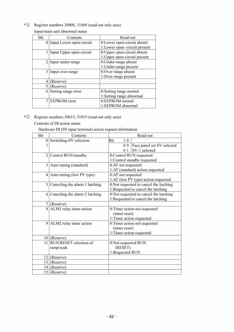
*④ Register numbers 30008, 31008 (read-out only area) Input/main unit abnormal status
Bit Contents Read-out 0 Input Lower open-circuit 0:Lower open-circuit absent
1:Lower open -circuit present 1 Input Upper open-circuit 0:Upper open-circuit absent
1:Upper open-circuit present 2 Input under-range 0:Under-range absent
1:Under-range present 3 Input over-range 0:Over-range absent
1:Over-range present 4 (Reserve) 5 (Reserve) 6 Setting range error 0:Setting range normal
1:Setting range abnormal 7 EEPROM error 0:EEPROM normal
1:EEPROM abnormal *⑤ Register numbers 30015, 31015 (read-out only area)
Contents of DI action status Hardware DI (DI input terminal) action request information Bit Contents Read-out
Bit 1 0 0 0 Face panel set SV selected
0 1
Switching-SV selection
0 1 SV-1 selected 2 Control RUN/standby 0:Control RUN requested
1:Control standby requested 3 Auto tuning (standard) 0:AT not requested
1:AT (standard) action requested 4 Auto tuning (low PV type) 0:AT not requested
1:AT (low PV type) action requested 5 Canceling the alarm 1 latching 0:Not requested to cancel the latching
1:Requested to cancel the latching 6 Canceling the alarm 2 latching 0:Not requested to cancel the latching
1:Requested to cancel the latching 7 (Reserve) 8 ALM1 relay timer action 0:Timer action not requested
(timer reset) 1:Timer action requested
9 ALM2 relay timer action 0:Timer action not requested (timer reset)
1:Timer action requested 10 (Reserve) 11 RUN/RESET selection of
ramp/soak 0:Not requested RUN
(RESET) 1:Requested RUN
12 (Reserve) 13 (Reserve) 14 (Reserve) 15 (Reserve)
-43-
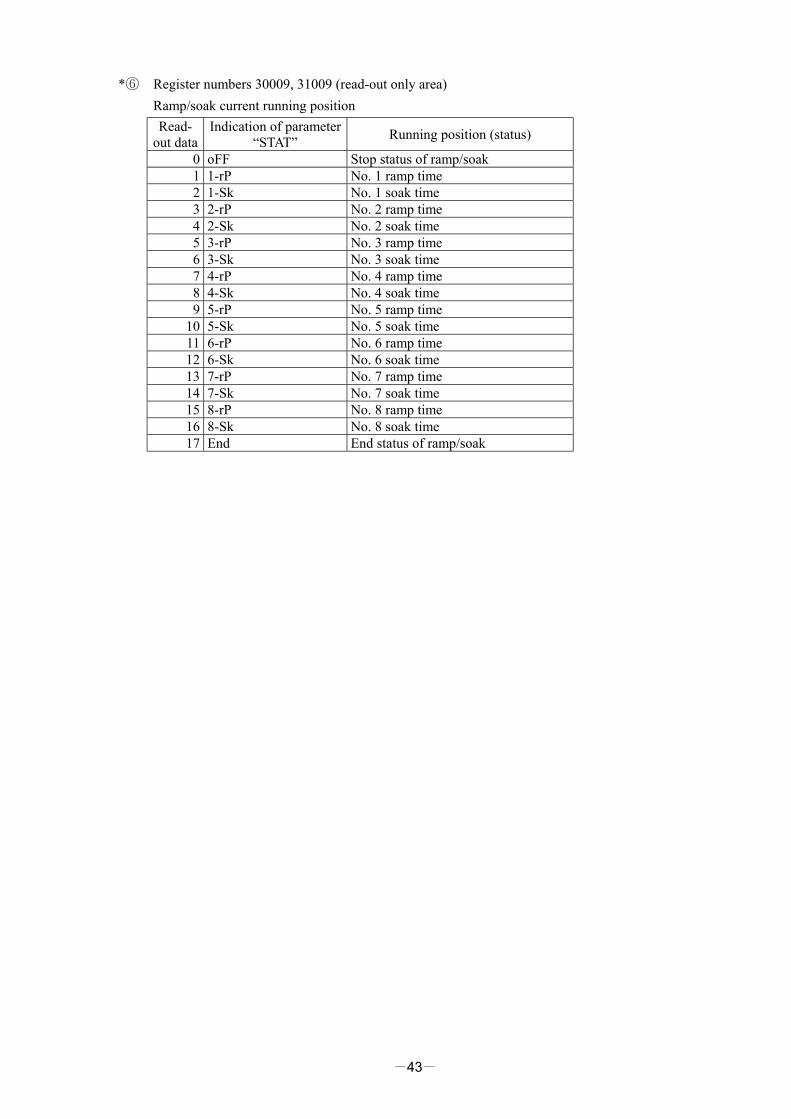
*⑥ Register numbers 30009, 31009 (read-out only area) Ramp/soak current running position Read-
out data Indication of parameter
“STAT” Running position (status)
0 oFF Stop status of ramp/soak 1 1-rP No. 1 ramp time 2 1-Sk No. 1 soak time 3 2-rP No. 2 ramp time 4 2-Sk No. 2 soak time 5 3-rP No. 3 ramp time 6 3-Sk No. 3 soak time 7 4-rP No. 4 ramp time 8 4-Sk No. 4 soak time 9 5-rP No. 5 ramp time
10 5-Sk No. 5 soak time 11 6-rP No. 6 ramp time 12 6-Sk No. 6 soak time 13 7-rP No. 7 ramp time 14 7-Sk No. 7 soak time 15 8-rP No. 8 ramp time 16 8-Sk No. 8 soak time 17 End End status of ramp/soak
-44-
8. SAMPLE PROGRAM This section concerns data read-out/write-in sample program by GW-BASIC*1 which operated on Windows 95*1 MS-DOS*1 PROMPT. Note that the program shown here is for reference for you to create a program and not for guaranteeing all actions. Before executing the program, make sure of the communication conditions in the following procedure. ・ Communication speed (baud rate), data length, stop bits and parity bit
Set in this program. Match the conditions with this instrument. Note) Cautions on using SEKISUI’s RS232C and RS485 converter unit (SI-30A)
In SI-30A, send data are received, added to start of the answer data from the slave station. After cleared data corresponding to the number of sending bytes, treat the remaining data as the answer data in the data receiving process.
*1: GW-BASIC, Windows 95 and MS-DOS are registered trademarks of Microsoft Corporation.
-45-
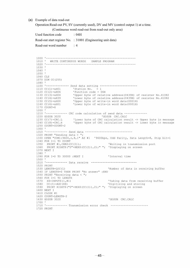
(a) Example of data read-out Operation:Read-out PV, SV (currently used), DV and MV (control output 1) at a time.
(Continuous word read-out from read-out only area) Used function code :04H Read-out start register No. :31001 (Engineering unit data) Read-out word number :4
1000 '------------------------------------------------------- 1010 ' WRITE CONTINUOUS WORDS SAMPLE PROGRAM 1020 '------------------------------------------------------- 1030 ' 1040 ' 1050 ' 1060 CLS 1070 DIM CC(255) 1080 ' 1100 '-------------- Send data setting ----------------------- 1110 CC(1)=&H01 'Station No. = 1 1120 CC(2)=&H06 'Function code = 06H 1130 CC(3)=&H04 'Upper byte of relative address(0439H) of resister No.41082 1140 CC(4)=&H39 'Lower byte of relative address(0439H) of resister No.41082 1150 CC(5)=&H00 'Upper byte of write-in word data(0001H) 1160 CC(6)=&H01 'Lower byte of write-in word data(0001H) 1170 COUNT=6 1200 ' 1210 '------------- CRC code calculation of send data -------------- 1220 GOSUB 3020 'GOSUB CRC.CALC 1230 CC(7)=CRC.L 'Lower byte of CRC calculation result -> Upper byte in message 1240 CC(8)=CRC.H 'Upper byte of CRC calculation result -> Lower byte in message 1250 COUNT=COUNT+2 1300 ' 1310 '------------- Send data ----------------------------- 1320 PRINT "Sending data > "; 1330 OPEN "COM1:9600,o,8,1" AS #1 '9600bps, Odd Parity, Data Length=8, Stop bit=1 1340 FOR I=1 TO COUNT 1350 PRINT #1,CHR$(CC(I)); 'Writing in transmission port 1360 PRINT RIGHT$("0"+HEX$(CC(I)),2);" "; 'Displaying on screen 1370 NEXT I 1380 ' 1390 FOR I=O TO 30000 :NEXT I 'Interval time 1500 ' 1510 '------------- Data receive ---------------------------- 1520 PRINT 1530 LENGTH=LOC(1) 'Number of data in receiving buffer 1540 IF LENGTH=0 THEN PRINT "No answer" :END 1550 PRINT "Receiving data < "; 1560 FOR I=1 TO LENGTH 1570 X$=INPUT$(1,#1) 'Taking data from receiving buffer 1580 CC(I)=ASC(X$) 'Digitizing and storing 1590 PRINT RIGHT$("0"+HEX$(CC(I)),2);" "; 'Displaying on screen 1600 NEXT I 1610 CLOSE #1 1620 COUNT=LENGTH-2 1630 GOSUB 3020 'GOSUB CRC.CALC 1700 ' 1710 '------------- Transmission error check ----------------------- 1720 PRINT
-46-
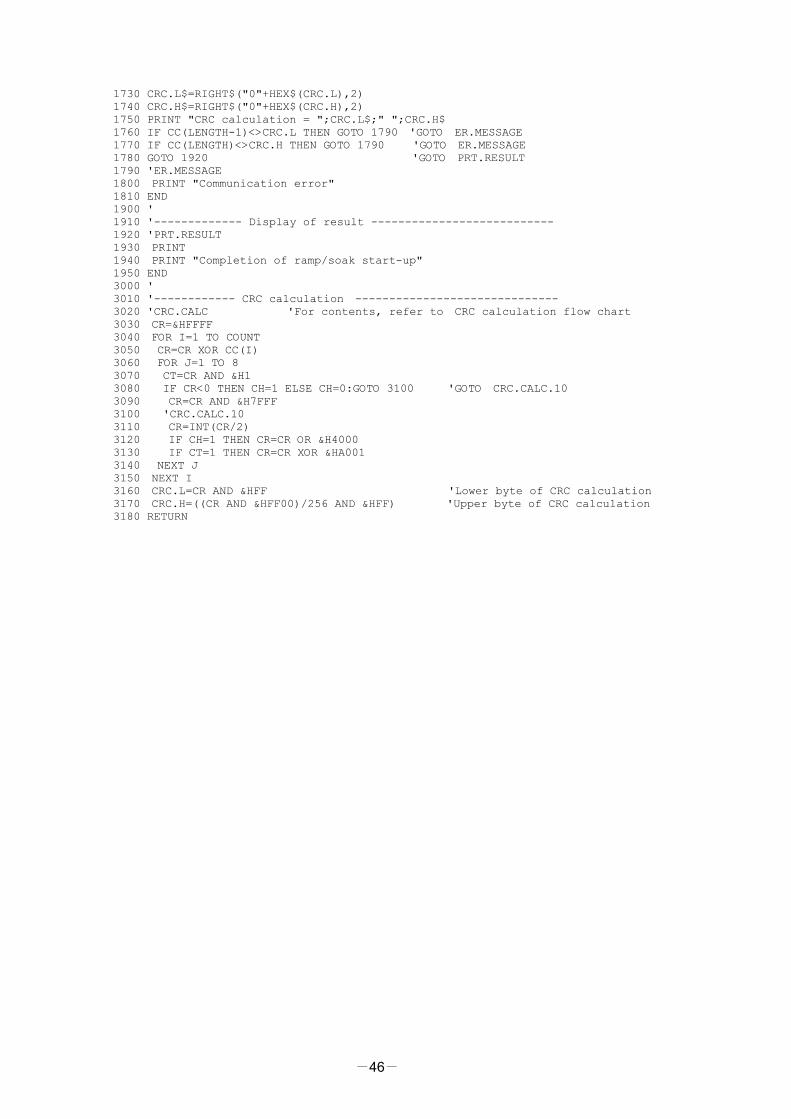
1730 CRC.L$=RIGHT$("0"+HEX$(CRC.L),2) 1740 CRC.H$=RIGHT$("0"+HEX$(CRC.H),2) 1750 PRINT "CRC calculation = ";CRC.L$;" ";CRC.H$ 1760 IF CC(LENGTH-1)<>CRC.L THEN GOTO 1790 'GOTO ER.MESSAGE 1770 IF CC(LENGTH)<>CRC.H THEN GOTO 1790 'GOTO ER.MESSAGE 1780 GOTO 1920 'GOTO PRT.RESULT 1790 'ER.MESSAGE 1800 PRINT "Communication error" 1810 END 1900 ' 1910 '------------- Display of result --------------------------- 1920 'PRT.RESULT 1930 PRINT 1940 PRINT "Completion of ramp/soak start-up" 1950 END 3000 ' 3010 '------------ CRC calculation ------------------------------ 3020 'CRC.CALC 'For contents, refer to CRC calculation flow chart 3030 CR=&HFFFF 3040 FOR I=1 TO COUNT 3050 CR=CR XOR CC(I) 3060 FOR J=1 TO 8 3070 CT=CR AND &H1 3080 IF CR<0 THEN CH=1 ELSE CH=0:GOTO 3100 'GOTO CRC.CALC.10 3090 CR=CR AND &H7FFF 3100 'CRC.CALC.10 3110 CR=INT(CR/2) 3120 IF CH=1 THEN CR=CR OR &H4000 3130 IF CT=1 THEN CR=CR XOR &HA001 3140 NEXT J 3150 NEXT I 3160 CRC.L=CR AND &HFF 'Lower byte of CRC calculation 3170 CRC.H=((CR AND &HFF00)/256 AND &HFF) 'Upper byte of CRC calculation 3180 RETURN
-47-
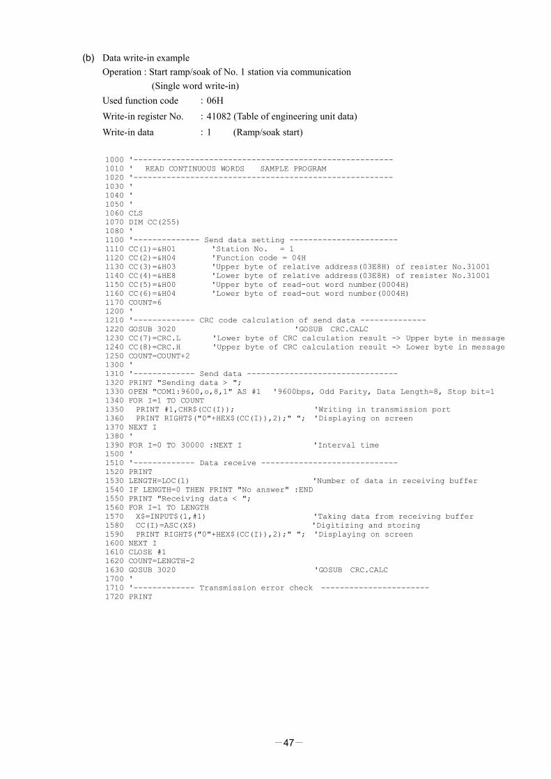
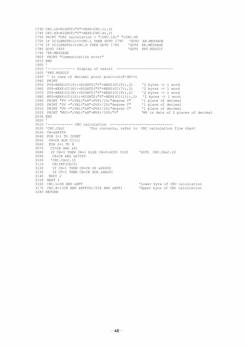
(b) Data write-in example Operation : Start ramp/soak of No. 1 station via communication
(Single word write-in) Used function code :06H Write-in register No. :41082 (Table of engineering unit data) Write-in data :11082 (Ramp/soak start)
1000 '------------------------------------------------------- 1010 ' READ CONTINUOUS WORDS SAMPLE PROGRAM 1020 '------------------------------------------------------- 1030 ' 1040 ' 1050 ' 1060 CLS 1070 DIM CC(255) 1080 ' 1100 '-------------- Send data setting ----------------------- 1110 CC(1)=&H01 'Station No. = 1 1120 CC(2)=&H04 'Function code = 04H 1130 CC(3)=&H03 'Upper byte of relative address(03E8H) of resister No.31001 1140 CC(4)=&HE8 'Lower byte of relative address(03E8H) of resister No.31001 1150 CC(5)=&H00 'Upper byte of read-out word number(0004H) 1160 CC(6)=&H04 'Lower byte of read-out word number(0004H) 1170 COUNT=6 1200 ' 1210 '------------- CRC code calculation of send data -------------- 1220 GOSUB 3020 'GOSUB CRC.CALC 1230 CC(7)=CRC.L 'Lower byte of CRC calculation result -> Upper byte in message 1240 CC(8)=CRC.H 'Upper byte of CRC calculation result -> Lower byte in message 1250 COUNT=COUNT+2 1300 ' 1310 '------------- Send data -------------------------------- 1320 PRINT "Sending data > "; 1330 OPEN "COM1:9600,o,8,1" AS #1 '9600bps, Odd Parity, Data Length=8, Stop bit=1 1340 FOR I=1 TO COUNT 1350 PRINT #1,CHR$(CC(I)); 'Writing in transmission port 1360 PRINT RIGHT$("0"+HEX$(CC(I)),2);" "; 'Displaying on screen 1370 NEXT I 1380 ' 1390 FOR I=0 TO 30000 :NEXT I 'Interval time 1500 ' 1510 '------------- Data receive ----------------------------- 1520 PRINT 1530 LENGTH=LOC(1) 'Number of data in receiving buffer 1540 IF LENGTH=0 THEN PRINT "No answer" :END 1550 PRINT "Receiving data < "; 1560 FOR I=1 TO LENGTH 1570 X$=INPUT$(1,#1) 'Taking data from receiving buffer 1580 CC(I)=ASC(X$) 'Digitizing and storing 1590 PRINT RIGHT$("0"+HEX$(CC(I)),2);" "; 'Displaying on screen 1600 NEXT I 1610 CLOSE #1 1620 COUNT=LENGTH-2 1630 GOSUB 3020 'GOSUB CRC.CALC 1700 ' 1710 '------------- Transmission error check ----------------------- 1720 PRINT
-48-
1730 CRC.L$=RIGHT$("0"+HEX$(CRC.L),2) 1740 CRC.H$=RIGHT$("0"+HEX$(CRC.H),2) 1750 PRINT "CRC calculation = ";CRC.L$;" ";CRC.H$ 1760 IF CC(LENGTH-1)<>CRC.L THEN GOTO 1790 'GOTO ER.MESSAGE 1770 IF CC(LENGTH)<>CRC.H THEN GOTO 1790 'GOTO ER.MESSAGE 1780 GOTO 1920 'GOTO PRT.RESULT 1790 'ER.MESSAGE 1800 PRINT "Communication error" 1810 END 1900 ' 1910 '------------- Display of result --------------------------- 1920 'PRT.RESULT 1930 ' In case of decimal point position(P-dP)=1 1940 PRINT 1950 PV$=HEX$(CC(4))+RIGHT$("0"+HEX$(CC(5)),2) '2 bytes -> 1 word 1960 SV$=HEX$(CC(6))+RIGHT$("0"+HEX$(CC(7)),2) '2 bytes -> 1 word 1970 DV$=HEX$(CC(8))+RIGHT$("0"+HEX$(CC(9)),2) '2 bytes -> 1 word 1980 MV$=HEX$(CC(10))+RIGHT$("0"+HEX$(CC(11)),2) '2 bytes -> 1 word 1990 PRINT "PV =";VAL("&H"+PV$)/10;"degree C" '1 place of decimal 2000 PRINT "SV =";VAL("&H"+SV$)/10;"degree C" '1 place of decimal 2010 PRINT "DV =";VAL("&H"+DV$)/10;"degree C" '1 place of decimal 2020 PRINT "MV1=";VAL("&H"+MV$)/100;"%" 'MV is data of 2 places of decimal 2030 END 3000 ' 3010 '------------ CRC calculation ------------------------------ 3020 'CRC.CALC 'For contents, refer to CRC calculation flow chart 3030 CR=&HFFFF 3040 FOR I=1 TO COUNT 3050 CR=CR XOR CC(I) 3060 FOR J=1 TO 8 3070 CT=CR AND &H1 3080 IF CR<0 THEN CH=1 ELSE CH=0:GOTO 3100 'GOTO CRC.CALC.10 3090 CR=CR AND &H7FFF 3100 'CRC.CALC.10 3110 CR=INT(CR/2) 3120 IF CH=1 THEN CR=CR OR &H4000 3130 IF CT=1 THEN CR=CR XOR &HA001 3140 NEXT J 3150 NEXT I 3160 CRC.L=CR AND &HFF 'Lower byte of CRC calculation 3170 CRC.H=((CR AND &HFF00)/256 AND &HFF) 'Upper byte of CRC calculation 3180 RETURN

-49-
9. TROUBLESHOOTING If the communication is unavailable, check the following items. □ Whether all devices related to communication are turned on. □ Whether connections are correct. □ Whether the number of connected instruments and connection distance are as specified □ Whether communication conditions coincide between the master station (host computer) and slave stations
(PXR) □ Transmission speed : 9600bps □ Data length : 8 bits □ Stop bit : 1 bit □ Parity : □odd
□even □none
□ Whether send/receive signal timing conforms to Section 5.4 in this manual. □ Whether the station No. designated as send destination by the master station coincides with the station No. of
the connected PXR □ Whether more than one instrument connected on the same transmission line shares the same station No. □ Whether the station No. of instruments is set at other than 0.
If it’s 0, the communication function does not work. □ Whether the 11th digit of type cord of this controller is M or V?.
(PXR4□□□□-□□MV□□-□)