microbial desalination cell technology: a review and a
TRANSCRIPT

H.M. Saeed et al. / Desalination 359 (2015) 1–14 1
Henna M. Saeed, Ghaleb A. Husseini ⁎, Sharifeh Yousef, Jawaria Saif, Sameer Al-Asheh, Abdullah Abu Fara, Sara Azzam, Rehab Khawaga, Ahmed Aidan Chemical Engineering Department, American University of Sharjah, P.O. Box 26666, United Arab Emirates
H I G H L I G H T S
• The MDC process is discussed.• Biofilms and biofilm formation as applied to MDCs are introduced.• Different MDC modifications are compared to conventional MDCs for water
treatment.• The issues of scale-up and practical limitations of MDCs are also addressed.• Three alternate designs for wastewater treatment plants with MDCs are evaluated.
Article history: Received 10 November 2014 Received in revised form 16 December 2014 Accepted 17 December 2014 Available online xxxx
The microbial desalination cell (MDC) is a newly-developed technology which integrates the microbial fuel cell (MFC) process and electrodialysis for wastewater treatment, water desalination and production of renewable energy. Due to free energy requirements and environmentally friendly technologies, MDC recently received considerable attention for desalination and wastewater treatment. The technology can either be used as a stand-alone process, or can be combined with other desalination processes, such as reverse osmosis (RO) or electrodialysis.
Keywords: Desalination Wastewater Microbial desalination cell
Recently, several different modifications of MDCs have been developed including stacked MDCs, biocathode MDCs and recirculation MDCs. This paper provides a general review of the MDC technology. The working principle of the conventional MDC system is discussed, followed by a brief introduction to biofilms and biofilm formation. The different modifications of MDCs and the various advantages and disadvantages associated with each, including the desalination performance and electricity generation are also considered. The issues of scale-up and practical availability of the MDC technology are discussed, followed by a detailed discussion and evaluation of a proposed design for a wastewater treatment plant integrating the MDC technology. A case study of a wastewater treatment plant integrated with MDC technology to simultaneously treat wastewater and desalinate seawater is also considered.
Microbial desalination cell technology: A review and a case study
https://doi.org/10.1016/j.desal.2014.12.024
1. Microbial desalination cells
Microbial desalination cell (MDC) has demonstrated the ability to treat wastewater with simultaneous production of electricity.
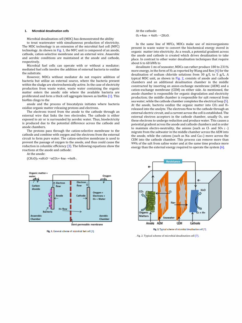
The MDC technology is an extension of the microbial fuel cell (MFC) technology. As shown in Fig. 1, the MFC unit is composed of an anode, cathode, cation-selective membrane and an external wire. Anaerobic and aerobic conditions are maintained at the anode and cathode, respectively.
Microbial fuel cells can operate with or without a mediator; mediated fuel cells involve the addition of external bacteria to oxidize the substrate.
However, MDCs without mediator do not require addition of bacteria but utilize an external source, where the bacteria present within the sludge are electrochemically active. In the case of electricity production from waste water, waste water containing the organic matter enters the anodic side where the available bacteria are proliferated and form a thick cell aggregate known as biofilm [1]. This biofilm clings to the
anode and the process of biocatalysis initiates where bacteria oxidize organic matter releasing protons and electrons.
The electrons travel from the anode to the cathode through an external wire that links the two electrodes. The cathode is either exposed to air or is surrounded by aerobic water. Thus, bioelectricity is produced due to the potential difference across the cathode and anode chambers.
The protons pass through the cation-selective membrane to the cathode and combine with oxygen and the electrons from the external circuit to form pure water. The cation-selective membrane is used to prevent the passage of oxygen to the anode, and thus could cause the reduction in columbic efficiency [3]. The following equations show the reactions at the anode and cathode:
At the anode: (CH2O)n +nH2O→nCO2+ 4ne− +4nH+.
At the cathode: O2 +4ne− + 4nH+→2H2O. In the same line of MFCs, MDCs make use of microorganisms
present in waste water to convert the biochemical energy stored in organic matter into electricity. As a result, a potential gradient across the anode and cathode is created which drives desalination to take place. In contrast to other water desalination techniques that require about 6 to 68 kWh to
desalinate 1 m3 of seawater, MDCs can rather produce 180 to 231% more energy, in the form of H2 as reported by Wang and Ren [4] for the desalination of sodium chloride solutions from 30 g/L to 5 g/L. A typical MDC unit, as shown in Fig. 2, consists of anode and cathode chambers and an additional desalination chamber in the middle constructed by inserting an anion-exchange membrane (AEM) and a cation-exchange membrane (CEM) on either side. As mentioned, the anode chamber is responsible for organic degradation and electricity production; the middle chamber is responsible for salt removal from sea water; while the cathode chamber completes the electrical loop [5]. At the anode, bacteria oxidize the organic matter into CO2 and H+
released into the anolyte. The electrons flow to the cathode through an external electric circuit, and a current across the cell is established. The external electron acceptors in the cathode chamber, usually O2, use these electrons to undergo reduction and produce water. This causes a potential gradient across the anode and cathode chambers and in order to maintain electro-neutrality, the anions (such as Cl− and SO4 2 −) migrate from the saltwater in the middle chamber across the AEM into the anode, while the cations (such as Na+ and Ca2+) move across the CEM into the cathode chamber. This process can remove more than 99% of the salt from saline water and at the same time produce more energy than the external energy required to operate the system [6].
. Fig. 2. Typical scheme of microbial desalination cell [7].

H.M. Saeed et al. / Desalination 359 (2015) 1–14 3
One of the most important parameters of MDC performance is the desalination rate (DR), which is greatly dependent on the salt concentration of the seawater. Typically, MDC is considered to be suitable for desalinating highly concentrated saltwater as the higher salt concentration would lower the ohmic resistance in the MDC, resulting in a high current density across the circuit and a higher DR. In addition, the salt concentration gradient in the middle desalination chamber, the anode and cathode chambers may also affect the desalination performance. Ideally, the salt concentration in the desalination chamber should be significantly higher than that of the electrolytes, since a low salt concentration could result in lowering the DR as dialysis takes place by the reverse concentration gradient between the saltwater in the desalination chamber and the electrolytes [8].
To the best knowledge of the authors, MDC was first studied in 2009 by a group of researchers from Tsinghua University, China, in collaboration with Penn State University, Pennsylvania [9]. The investigators considered the design of a cubic-shaped MFC which consisted of three chambers instead of two, separated by AEM and CEM clampers. The volumes of the anode, desalination and cathode chambers were 27, 3 and 27 mL, respectively. Introducing carbon felt into the cathode and anode chambers, as electrode material, reduced the volumes of the corresponding chambers from 27 to 11 mL. A 5 mm diameter graphite rod was pushed into the carbon felt and a 1.6 g/L solution of sodium acetate was added to the anode chamber. Ferriccyanide catholyte was fed into the cathode chamber and the desalination chamber was filled with NaCl with different concentrations, namely 5, 20 and 35 g/L. The external resistance of the cell was maintained at 200 Ω [10]. The results showed a power production of 31 W/m3 along with 90% salt removal in a single desalination cycle. As the salt was being removed, it was also observed that the ohmic resistance of the cell increased from 25 Ω to 970 Ω towards the end of the cycle [11].
2. Biofilms
Accumulation of bacteria in a microbial community with layers of complex microcolonies is called a biofilm. Biofilms accommodate one or more microbial species to live together by their adhesion to the glue-like substance they excrete. Biofilms are bonded together by a matrix consisting of polysaccharides and proteins known as slime [11]. The formation of the colony is restricted by the suitability of the surface and the surrounding environmental conditions [12] including temperature and moisture level. After finding the appropriate surface conditions, the cells adhere and start to multiply by cellular division as shown in Fig. 3 [11].
The biofilm allows the arrival of other microorganisms to the surface by making more diverse adhesion sites available. These advantages include the transfer of biological material between the species which in turn helps in providing shelter to the entire community from the antimicrobials [13]. It is
relevant to mentioned here that the biofilm thickness, biomass and density are directly proportional to its age [14].
The growth of biofilms is rather a slow process [16]. There are four stages in the life cycle of a biofilm; these are illustrated in Fig. 3. The detachment, fourth stage, may leave behind a hollow mound that leads to the termination of a biofilm [17]. The shape of the biofilm can be studied using scanning electron microscope (SEM) micrographs at different elapsed operation times, and chloroform fumigation–extraction and DNA extraction methods [18].
A biofilm grown in the anodic chamber of a MDC acts as an anodic catalyst and helps in the rapid respiration of the bacteria, which in turn produces more current [19]. The biofilm bacteria are capable of transferring electrons to the anode without the need of an electron acceptor [20]. Therefore, the availability of biofilm along the anodic chamber leads to an increase in current density. However, a few factors need to be considered when dealing with biofilms. These include the age and thickness of the biofilms both of which play an essential role in increasing the efficiency of current production. With the increase in the biomass, the current density production decreases as the biomass prevents the penetration of the substrate. Additionally, increasing the biomass of the biofilm does not necessarily increase the current density possibly due to the presence of voids in the interior of the biofilm [21]. 3. Microbial desalination cell configurations
Table 1 summarizes the main characteristics of the different MDC configurations. Discussion of these configurations as well as their main advantages follows.
3.1. Air cathode microbial desalination cell
The concept of MDCs was first attempted using ferricyanide as catholyte. Despite its ability to produce higher cathode potentials and achieve faster reduction kinetics, ferricyanide is not suitable for largescale processes due to high costs and toxic characteristics. Thus, an air cathode MDC, Fig. 4, may be used in which oxygen is used as a terminal electron acceptor (TEA) due to its high reduction potential and costeffectiveness [22]. The air cathode MDC was capable of reducing the salinity of the water by 63% in a single cycle using carbon cloth electrode with platinum as catalyst [23]. Alternatively, cobalt tetramethoxyphenylporphyrin and activated carbon can also be used so that cobalt tetramethoxyphenylporphyrin acts as a catalyst while activated carbon serves to increase the surface area for further improve of MDC performance. Using atmospheric oxygen as the electron acceptor is also beneficial in terms of environmental sustainability since oxygen has negligible toxic effects compared to other chemicals.
One of the disadvantages of an air cathode MDC is that the redox kinetics in ambient conditions is slow compared to that using other catholytes; this would necessitate the need for more expensive catalytic
Fig. 3. Stages of biofilm formation on a surface [15]. 4 H.M. Saeed et al. / Desalination 359 (2015) 1–13
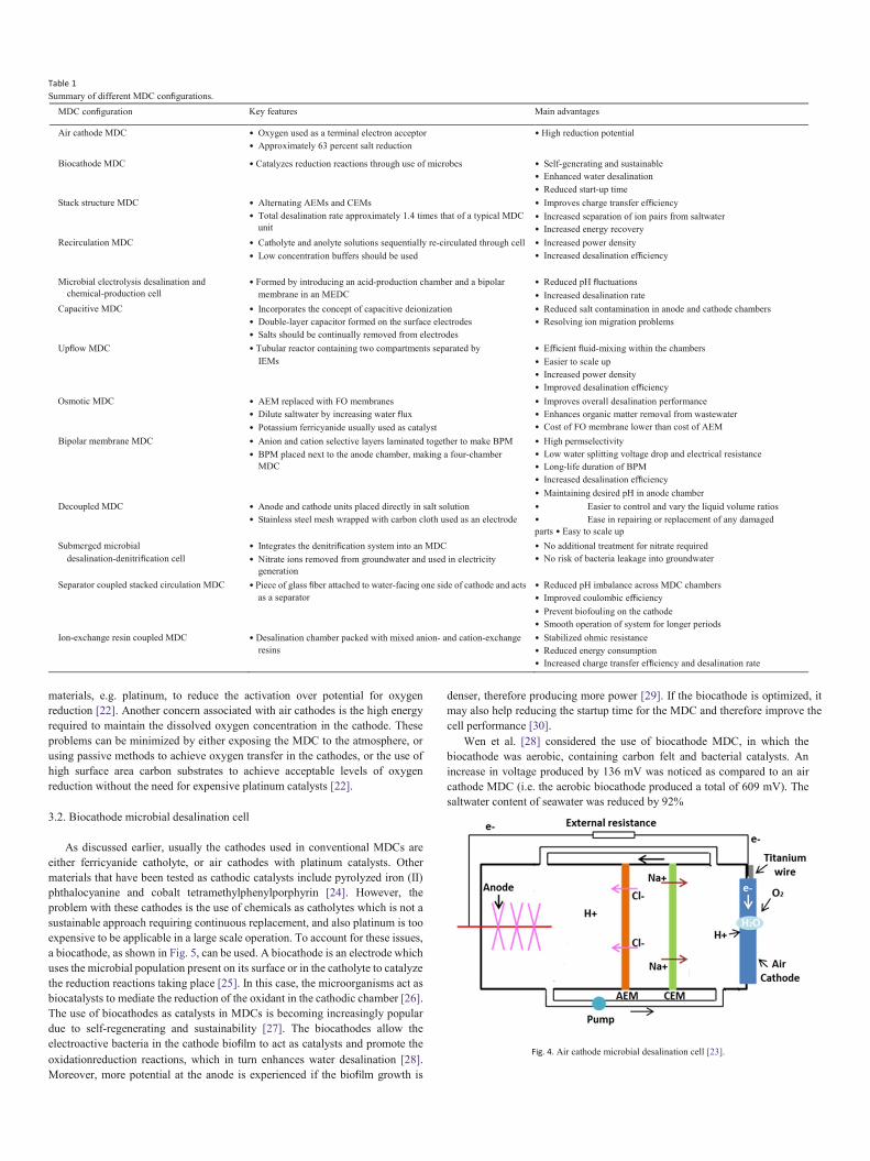
Table 1 Summary of different MDC configurations.
MDC configuration Key features Main advantages
Air cathode MDC • Oxygen used as a terminal electron acceptor • Approximately 63 percent salt reduction
• High reduction potential
Biocathode MDC • Catalyzes reduction reactions through use of microbes • Self-generating and sustainable • Enhanced water desalination • Reduced start-up time
Stack structure MDC • Alternating AEMs and CEMs • Total desalination rate approximately 1.4 times that of a typical MDC
unit
• Improves charge transfer efficiency • Increased separation of ion pairs from saltwater • Increased energy recovery
Recirculation MDC • Catholyte and anolyte solutions sequentially re-circulated through cell • Low concentration buffers should be used
• Increased power density • Increased desalination efficiency
Microbial electrolysis desalination and chemical-production cell
• Formed by introducing an acid-production chamber and a bipolar membrane in an MEDC
• Reduced pH fluctuations • Increased desalination rate
Capacitive MDC • Incorporates the concept of capacitive deionization • Double-layer capacitor formed on the surface electrodes • Salts should be continually removed from electrodes
• Reduced salt contamination in anode and cathode chambers • Resolving ion migration problems
Upflow MDC • Tubular reactor containing two compartments separated by IEMs
• Efficient fluid-mixing within the chambers • Easier to scale up • Increased power density • Improved desalination efficiency
Osmotic MDC • AEM replaced with FO membranes • Dilute saltwater by increasing water flux • Potassium ferricyanide usually used as catalyst
• Improves overall desalination performance • Enhances organic matter removal from wastewater • Cost of FO membrane lower than cost of AEM
Bipolar membrane MDC • Anion and cation selective layers laminated together to make BPM • BPM placed next to the anode chamber, making a four-chamber
MDC
• High permselectivity • Low water splitting voltage drop and electrical resistance • Long-life duration of BPM • Increased desalination efficiency • Maintaining desired pH in anode chamber
Decoupled MDC • Anode and cathode units placed directly in salt solution • Stainless steel mesh wrapped with carbon cloth used as an electrode
• Easier to control and vary the liquid volume ratios • Ease in repairing or replacement of any damaged parts • Easy to scale up
Submerged microbial desalination-denitrification cell
• Integrates the denitrification system into an MDC • Nitrate ions removed from groundwater and used in electricity
generation
• No additional treatment for nitrate required • No risk of bacteria leakage into groundwater
Separator coupled stacked circulation MDC • Piece of glass fiber attached to water-facing one side of cathode and acts as a separator
• Reduced pH imbalance across MDC chambers • Improved coulombic efficiency • Prevent biofouling on the cathode • Smooth operation of system for longer periods
Ion-exchange resin coupled MDC • Desalination chamber packed with mixed anion- and cation-exchange resins
• Stabilized ohmic resistance • Reduced energy consumption • Increased charge transfer efficiency and desalination rate
materials, e.g. platinum, to reduce the activation over potential for oxygen reduction [22]. Another concern associated with air cathodes is the high energy required to maintain the dissolved oxygen concentration in the cathode. These problems can be minimized by either exposing the MDC to the atmosphere, or using passive methods to achieve oxygen transfer in the cathodes, or the use of high surface area carbon substrates to achieve acceptable levels of oxygen reduction without the need for expensive platinum catalysts [22].
3.2. Biocathode microbial desalination cell
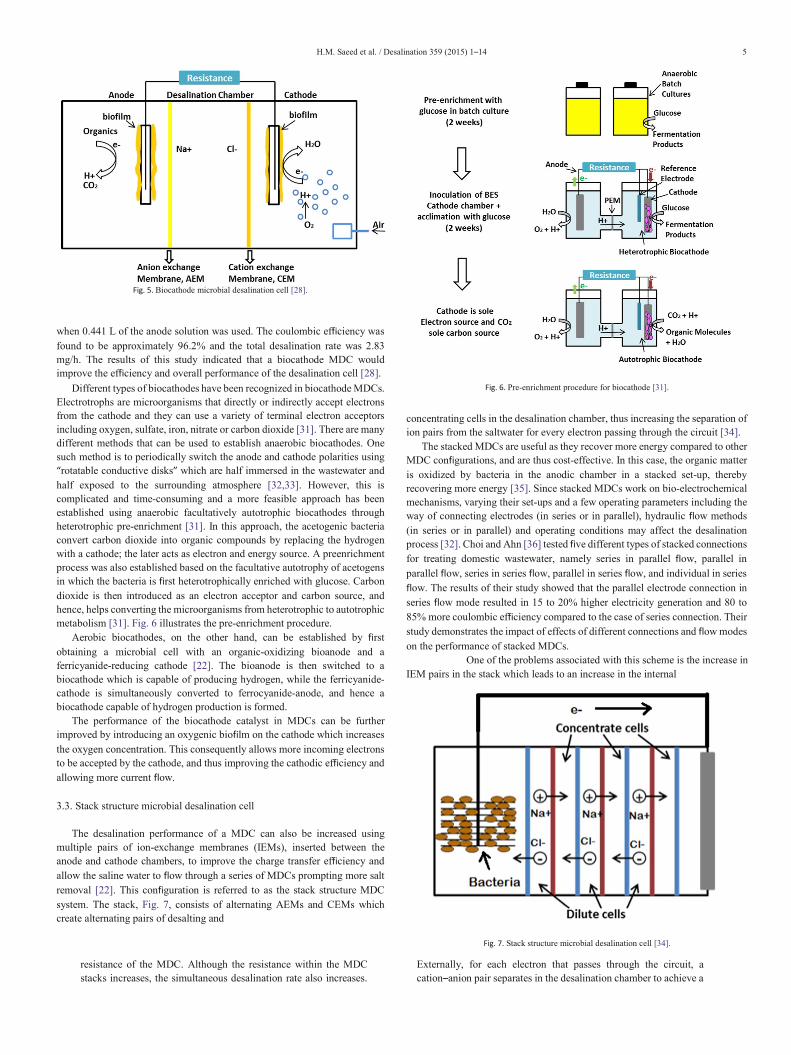
As discussed earlier, usually the cathodes used in conventional MDCs are either ferricyanide catholyte, or air cathodes with platinum catalysts. Other materials that have been tested as cathodic catalysts include pyrolyzed iron (II) phthalocyanine and cobalt tetramethylphenylporphyrin [24]. However, the problem with these cathodes is the use of chemicals as catholytes which is not a sustainable approach requiring continuous replacement, and also platinum is too expensive to be applicable in a large scale operation. To account for these issues, a biocathode, as shown in Fig. 5, can be used. A biocathode is an electrode which uses the microbial population present on its surface or in the catholyte to catalyze the reduction reactions taking place [25]. In this case, the microorganisms act as biocatalysts to mediate the reduction of the oxidant in the cathodic chamber [26]. The use of biocathodes as catalysts in MDCs is becoming increasingly popular due to self-regenerating and sustainability [27]. The biocathodes allow the electroactive bacteria in the cathode biofilm to act as catalysts and promote the oxidationreduction reactions, which in turn enhances water desalination [28]. Moreover, more potential at the anode is experienced if the biofilm growth is
denser, therefore producing more power [29]. If the biocathode is optimized, it may also help reducing the startup time for the MDC and therefore improve the cell performance [30].
Wen et al. [28] considered the use of biocathode MDC, in which the biocathode was aerobic, containing carbon felt and bacterial catalysts. An increase in voltage produced by 136 mV was noticed as compared to an air cathode MDC (i.e. the aerobic biocathode produced a total of 609 mV). The saltwater content of seawater was reduced by 92%
Fig. 4. Air cathode microbial desalination cell [23].
H.M. Saeed et al. / Desalination 359 (2015) 1–14 5
Fig. 5. Biocathode microbial desalination cell [28].
when 0.441 L of the anode solution was used. The coulombic efficiency was found to be approximately 96.2% and the total desalination rate was 2.83 mg/h. The results of this study indicated that a biocathode MDC would improve the efficiency and overall performance of the desalination cell [28].
Different types of biocathodes have been recognized in biocathode MDCs. Electrotrophs are microorganisms that directly or indirectly accept electrons from the cathode and they can use a variety of terminal electron acceptors including oxygen, sulfate, iron, nitrate or carbon dioxide [31]. There are many different methods that can be used to establish anaerobic biocathodes. One such method is to periodically switch the anode and cathode polarities using “rotatable conductive disks” which are half immersed in the wastewater and half exposed to the surrounding atmosphere [32,33]. However, this is complicated and time-consuming and a more feasible approach has been established using anaerobic facultatively autotrophic biocathodes through heterotrophic pre-enrichment [31]. In this approach, the acetogenic bacteria convert carbon dioxide into organic compounds by replacing the hydrogen with a cathode; the later acts as electron and energy source. A preenrichment process was also established based on the facultative autotrophy of acetogens in which the bacteria is first heterotrophically enriched with glucose. Carbon dioxide is then introduced as an electron acceptor and carbon source, and hence, helps converting the microorganisms from heterotrophic to autotrophic metabolism [31]. Fig. 6 illustrates the pre-enrichment procedure.
Aerobic biocathodes, on the other hand, can be established by first obtaining a microbial cell with an organic-oxidizing bioanode and a ferricyanide-reducing cathode [22]. The bioanode is then switched to a biocathode which is capable of producing hydrogen, while the ferricyanide-cathode is simultaneously converted to ferrocyanide-anode, and hence a biocathode capable of hydrogen production is formed.
The performance of the biocathode catalyst in MDCs can be further improved by introducing an oxygenic biofilm on the cathode which increases the oxygen concentration. This consequently allows more incoming electrons to be accepted by the cathode, and thus improving the cathodic efficiency and allowing more current flow.
3.3. Stack structure microbial desalination cell
The desalination performance of a MDC can also be increased using multiple pairs of ion-exchange membranes (IEMs), inserted between the anode and cathode chambers, to improve the charge transfer efficiency and allow the saline water to flow through a series of MDCs prompting more salt removal [22]. This configuration is referred to as the stack structure MDC system. The stack, Fig. 7, consists of alternating AEMs and CEMs which create alternating pairs of desalting and
Fig. 6. Pre-enrichment procedure for biocathode [31].
concentrating cells in the desalination chamber, thus increasing the separation of ion pairs from the saltwater for every electron passing through the circuit [34].
The stacked MDCs are useful as they recover more energy compared to other MDC configurations, and are thus cost-effective. In this case, the organic matter is oxidized by bacteria in the anodic chamber in a stacked set-up, thereby recovering more energy [35]. Since stacked MDCs work on bio-electrochemical mechanisms, varying their set-ups and a few operating parameters including the way of connecting electrodes (in series or in parallel), hydraulic flow methods (in series or in parallel) and operating conditions may affect the desalination process [32]. Choi and Ahn [36] tested five different types of stacked connections for treating domestic wastewater, namely series in parallel flow, parallel in parallel flow, series in series flow, parallel in series flow, and individual in series flow. The results of their study showed that the parallel electrode connection in series flow mode resulted in 15 to 20% higher electricity generation and 80 to 85% more coulombic efficiency compared to the case of series connection. Their study demonstrates the impact of effects of different connections and flow modes on the performance of stacked MDCs.
One of the problems associated with this scheme is the increase in IEM pairs in the stack which leads to an increase in the internal
Fig. 7. Stack structure microbial desalination cell [34].
resistance of the MDC. Although the resistance within the MDC stacks increases, the simultaneous desalination rate also increases.
Externally, for each electron that passes through the circuit, a cation–anion pair separates in the desalination chamber to achieve a
6 H.M. Saeed et al. / Desalination 359 (2015) 1–14
closed loop. Therefore, introducing stacks increases the charge transfer efficiency and speeds up the desalination process [37]. In addition, an increase in the number of cell pairs reduces the voltage required in each cell allowing a greater net energy gain. Moreover, with the use of thin IEMs and desalination chambers, the internal resistance is reduced and more efficient separation of ions and water desalination can be achieved [38]. Therefore, the stacked MDC system should be optimized in such a way so as to generate maximum electricity from the exoelectrogens without allowing a substantial increase in the internal resistance of the system.
Another factor that may affect the MDC performance is the pH imbalance between the anode and cathode chambers when more than one chamber is used between the electrodes. A large decrease in the anode pH, for instance, can decrease the microbial activity in the anodic chamber, while anincrease in the pH in the cathode chamber can lead to significant potential losses, therefore reducing process efficiency [39]. The production of protons by the microorganisms reduces the pH of the anolyte. This pH imbalance is more pronounced in the single-cell structure than that of the stack-structure MDC; as in the latter the organic medium first flows through the anode and cathode chambers of the first MDC, and then moves on to flow into the next MDC, thereby eliminating large pH fluctuations [39]. The results of Shehab et al. [35] showed that the anolyte pH in the stack MDC structure decreased from approximately 7.03 to 6.30 and the catholyte pH increased from approximately 7.40 to 11.60. This change in pH is therefore much lower than in single MDCs, suggesting that stack MDC structure can significantly reduce pH imbalances between the anode and cathode chambers [35].
Kim and Logan [38] investigated the stacked MDC and its effects on DR and external resistance. Extremely thin stacks were used in this case as they increase the extent and efficiency of desalination. Such scenario also allows high power densities across the stacks by minimizing the ohmic resistance. The results of those authors showed that using a 10 Ω external resistance, the maximum DR for the stacked MDC was 0.0252 g/h, which is approximately 1.4 times higher than that for the typical MDC unit [37].
Another study [39] in which four hydraulically connected MDCs showed that increasing the hydraulic retention time of the salt solution from 1 to 2 days increased the salt removal rates from approximately 76% to 97%. At the same time, the coulombic efficiency decreases from approximately 49% to 35%. This demonstrates that increasing the number of MDC units can have a positive effect on the desalination efficiency [39].
3.4. Recirculation microbial desalination cell
Recent studies showed that the current produced by MDC increases linearly with time during the first 10 h, after which it starts to decrease. The decrease in the current can be explained by substrate depletion; however, further studies disapproved this explanation [5]. It has been shown that the pH value has a direct effect on the performance of MDCs in terms of power generation and desalination [34]. Thus, a pH control mechanism should be applied to prevent any pH imbalances inside the cell. Review of pH imbalances inside the cell is followed.
In a conventional MDC, the different chambers of the cell are separated by ion-exchange membranes (IEM). A major problem arises from the blockage effect of these membranes to both protons and hydroxyls produced in the redox reactions, in both the anode and cathode chambers [34]. In the anode, the oxidation of the organic material releases protons which are not allowed to diffuse to the cathode chamber, where hydroxyls are being generated through the reduction reaction [10,40,41]. This may create a significant pH
imbalance inside the cell in which the pH decreases in the anode, and increases in the cathode. It is known that the pH imbalance decreases the desalination efficiency and power density generation [10,34,41,42]. Moreover, the pH imbalance effects on the anode efficiency are more pronounced than the cathode due to the presence of the microorganism and its sensitivity to pH variation [10,34,41,42]. This high sensitivity is a result of the strong influence of enzyme activities by pH; in general, most enzymes can operate in a pH range of 6–8 [43]. However, after one desalination cycle, the pH value of the anolyte can reach as low as 4.1 which results in acidic environment for the microorganisms [41]. On the other hand, the pH value of the catholyte can reach as high as 10 which may lead to considerable reduction in the cell voltage [41]. Kim and Logan [34] reported that a unit increase in the catholyte pH above neutrality (pH 7.0) can produce a 59 mV reduction in the cell voltage. The pH imbalances across the MDC can be minimized by increasing the volume of the anolyte present and by adding acids and bases into the cell [41,37,44]. However, this may increase the amount of energy required by the process, and adding pH-controlling chemicals could be costly [41].
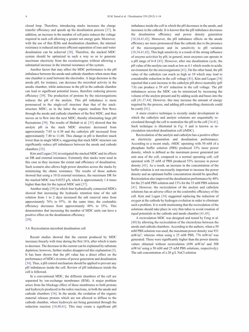
A more creative technique is recently under development in which the catholyte and anolyte solutions are sequentially re-circulated through the cell to neutralize the pH in the cell [34,41]. Such technique is illustrated in Fig. 8 and is known as re-circulation microbial desalination cell (rMDC).
Recirculation of the anolyte and catholyte has a positive effect on electricity generation and desalination performance. According to a recent study, rMDC operating with 50 mM of a phosphate buffer solution (PBS) produced 33% more power density, which is defined as the maximum power generated per unit area of the cell, compared to a normal operating cell; cell operated with 25 mM of PBS produced 53% increase in power density [41]. As a result, an increase in the concentration of the buffer solution is not necessarily important to increase the power density and an optimum buffer concentration should be specified. Recirculation also improved the desalination performance by 48% for the 25 mM PBS solution and 13% for the 33 mM PBS solution [41]. However, the recirculation of the anolyte and catholyte solutions has an adverse effect on the coulombic efficiency of the cell. Kim and Logan [34] suggested replacing the reduction of oxygen at the cathode by hydrogen evolution in order to eliminate such a problem. It is worth mentioning that the recirculation of the solutions should take place in very thin tubes to avoid creation of equal potentials in the cathode and anode chamber [41,45].
A recirculation MDC was designed and tested by Feng et al. [40] by allowing the recirculation of the electrolytes between the anode and cathode chambers. According to the authors, when a 50 mM PBS solution was used, the maximum power density was 931 mW/m2; whereas when using a 25 mM PBS, 776 mW/m2 was generated. These were significantly higher than the power density values obtained without recirculation (698 mW/m2 and 508 mW/m2 using a 50 mM and 25 mM PBS solutions, respectively). The salt concentration of a 20 g/L NaCl solution
H.M. Saeed et al. / Desalination 359 (2015) 1–14 7
Fig. 8. Recirculation microbial desalination cell [34].
was also reduced by 34% with the use of 50 mM PBS and 37% with the use of 25 mM PBS. This indicates that the rMDC is more effective in enhancing desalination efficiency when a buffer solution of lower concentration is used.
3.5. Microbial electrolysis desalination and chemical-production cell
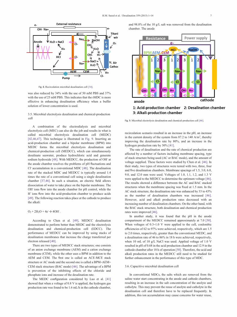
A combination of the electrodialysis and microbial electrolysis cell (MEC) can also do the job and results in what is called microbial electrolysis desalination cell (MEDC) [42,46,47]. This technique is illustrated in Fig. 9. Inserting an acid-production chamber and a bipolar membrane (BPM) into MEDC forms the microbial electrolysis desalination and chemical-production cell (MEDCC), which can simultaneously desalinate seawater, produce hydrochloric acid and generate sodium hydroxide [48]. With MEDCC, the production of OH− at the anode chamber resolves the problems of pH fluctuations and Cl− accumulation in a conventional MDC [48]. The desalination rate of the stacked MDC and MEDCC is typically around 1.4 times the rate of a conventional cell using a single desalination chamber [37,46]. In such a situation, an electric field allows dissociation of water to take place on the bipolar membrane. The OH− ions flow into the anode chamber for pH control, while the H+ ions flow into the acid-production chamber to produce acids [49]. The following reaction takes place at the cathode to produce the alkali:
O2 + 2H2O + 4e−→ 4OH−.
According to Chen et al. [49], MEDCC desalination demonstrated to perform better than MEDC and the electrolysis desalination and chemical-production cell (EDCC). The performance of MEDCC can be improved by using stacks of desalination membranes that increase the charge transferred per electron released [40].
There are two types of MEDCC stack structures; one consists of an anion exchange membrane (AEM) and a cation exchange membrane (CEM), while the other uses a BPM in addition to the AEM and CEM. The first one is called an ACE-MCE stack structure or AC mode and the second one is called a BPM–AEM–CEM stack structure (BAC mode) [46]. The advantage of a BPM is prevention of the inhibiting effects of the chloride and phosphate ions and increase of the desalination rate.
The MEDC configuration considered by Luo et al. [41] showed that when a voltage of 0.8 V is applied, the hydrogen gas production rate was found to be 1.6 mL/h in the cathode chamber,
and 98.8% of the 10 g/L salt was removed from the desalination chamber. The anode
Fig. 9. Microbial electrolysis desalination and chemical-production cell [46]. recirculation scenario resulted in an increase in the pH, an increase in the current density of the system from 87.2 to 140 A/m3, thereby improving the desalination rate by 80%, and an increase in the hydrogen production rate by 30% [41].
The rate of desalination and the rate of chemical production are affected by a number of factors including membrane spacing, type of stack structure being used (AC or BAC mode), and the amount of voltage supplied. These factors were studied by Chen et al. [46]. In their study, two types of structures were tested with two, three, four and five desalination chambers. Membrane spacings of 1.5, 3.0, 6.0, 9.0, and 12.0 mm were used. Voltages of 1.0, 1.1, 1.2, and 1.3 V were applied to the MEDCC to determine the optimum voltage [46]. The results showed a difference between the AC and BAC stacked structures when the membrane spacing was fixed at 1.5 mm. In the AC stack structure, the desalination rate was enhanced by 33 to 43% as the number of desalination chambers was increased [46]. However, acid and alkali production rates decreased with an increasing number of desalination chambers. On the other hand, with the BAC stack structure, both desalination and chemical production rates were improved [46].
In another study, it was found that the pH in the anode compartment of the MEDCC remained approximately at 7.0 [50]. When voltages of 0.3–1.0 V were applied to the cell, coulombic efficiencies of 62 to 97% were achieved, respectively, which are 1.5 to 2.0 times, respectively, greater than the conventional MEDC, and a desalination rate of 46 to 86% in 18 h were achieved, respectively, when 10 mL of 10 g/L NaCl was used. Applied voltage of 1.0 V resulted in pH of 0.68 in the acid production chamber and 12.9 in the cathode chamber after 18 h of operation [50]. Therefore, the acid and alkali production rates in the MEDCC still need to be studied for further enhancement in the performance of this type of MDC.
3.6. Capacitive microbial desalination cell
In conventional MDCs, the salts which are removed from the saline water start concentrating in the anode and cathode chambers, resulting in an increase in the salt concentration of the anolyte and catholyte. This may prevent the reuse of anolyte and catholyte in the desalination cell and therefore have to be replaced frequently. In addition, this ion accumulation may cause concerns for water reuse,

8 H.M. Saeed et al. / Desalination 359 (2015) 1–14
where the total dissolved solids (TDS) is regulated [51,52,8]. To avoid this problem, a capacitive MDC (cMDC) scheme, Fig. 10, has been developed which considered the salt removal by incorporating
the concept of capacitive deionization into the system [8,53]. Using a double-layer capacitor formed on the
high surface electrodes, the ions can be adsorbed when a saline solution flows between the two charged electrodes. The ions from the saline water are adsorbed by a double-layer capacitor on the surface electrodes, and when the potential gradient has been removed, the ions are allowed to flow back into the liquid. This way, the saltwater is deionized by “electrochemical salt adsorption” on the electrodes without the anode and cathode chambers being contaminated by the salt [8,53].
3.7. Upflow microbial desalination cell
The upflow MDC (UMDC), shown in Fig. 11, is a tubular unit with two compartments separated by IEMs; with the inner compartment is the anode chamber being filled with graphite granules. The graphite granules provide an increased surface area for the oxidation reactions to take place. Two graphite rods are also immersed into the graphite granules as current collectors that allow transfer of electrons. The anode chamber is then enclosed with an anion-exchange membrane tube. The outer compartment represents the desalination chamber containing the saline water. This compartment is then sealed with a cation-exchange membrane tube. Since a tubular form of the electrodes is maintained, an increased surface area is provided for desalination to progress [54]. The catalyst used in the UMDC is a mixture of platinum and carbon which is applied to the outer layer of the CEM tube. It is
Fig. 10. Capacitive microbial desalination cell [53].
further layered with carbon cloth around the reactor to make the cathode, thus no need for the cathode chamber in this case [44].
In the UMDC, the saline water generally enters from the bottom, while the desalinated water is positioned to leave from the top of the anodic chamber. The upflow MDC has unique benefits, since mixing of fluids within the chambers is achieved without agitation, and recovering more than 100% of the water due to water osmosis is a feasible option with such technique [55]. This allows microbes in the anodic chamber to remain in suspension and efficiently carry out sufficient oxidation of organic matter [56].
If the UMDC is employed before the RO unit in a desalination plant, it helps in lowering the energy costs by 22%; however, a much longer retention time is needed which would require a larger reactor volume, thereby increasing capital costs [44]. The limitation to such a setup is
Fig. 11. Upflow microbial desalination cell [44].
the resistance within the anode and cathode which limits the transfer of ions. Thus, by optimizing reaction rates, configuring UMDCs properly and by choosing proper anodic bacteria and employing efficient catalysts, a higher power density and efficient desalination can be achieved [57]. A pH imbalance is also encountered in the UMDC which can be controlled by maintaining the resistance in the external circuit [58]. Also, in anaerobic anode setups, the accumulation of protons in the anodic chamber decreases its pH, whereby the circulation of anode effluent to the cathode is carried out to compensate for the proton loss in the cathodic chamber [59].

H.M. Saeed et al. / Desalination 359 (2015) 1–14 9
3.8. Osmotic microbial desalination cell
Forward osmosis (FO) is a technique in water desalination in which a water flux is created between two solutions, one called the feed solution while the other is the draw solution [60–64]. The feed solution has a higher water potential than the draw solution and a water flux is created due to concentration gradient [34,60–62]. Attempts to integrate FO in microbial desalination cells (MDCs) and microbial fuel cells (MFCs) are reported by replacing the ion-exchange membranes (IEMs) with FO membranes [34,60,65]. Such modifications of MDCs or MFCs are referred to as osmotic MDCs or osmotic MFCs. The FO membrane allows water to pass through, but at the same time it significantly reduces the transport of ions from the middle chamber to both electrode chambers [60,62]. In this case, the salts are not removed, but they are rather concentrated. The advantage of replacing ion-exchange membranes with FO membranes is more pronounced in MFCs than that in MDCs. The osmotic MDC, Fig. 12, can achieve three main goals simultaneously: treating the waste water, generating electricity and diluting the saline water which is used as a cathode [60,63]. Replacing IEMs with FO membranes still presents several challenges that should be addressed. FO membranes are more susceptible to fouling than IEMs, which may increase the internal resistance of the cell significantly and reduce the water flux [34]. However, some studies showed that fouled FO membranes could increase current generation [59]. In fact, FO membranes integrated in MDC are not yet fully understood and more studies are required in this area. Moreover, the osmotic MDC performance in terms of salt removal can be varied by changing the orientation of the FO membrane [60]. The FO membrane can be placed in a pressure retarded osmosis (PRO) orientation or a forward osmosis (FO) orientation [60]. In the PRO orientation, the membrane is installed in a position in which the support layer faces the anolyte and the active layer faces the catholyte [60]. In the FO orientation, the positions of the layers are reversed. Zhang et al. [62] reported that the FO orientation results in more water flux and dilution than the PRO mode. However, the results are contradictory to previous studies on FO membrane orientation [60]. One way to explain this discrepancy is to recognize that osmotic MDCs are not a typical osmotic unit. In osmotic MDCs, the driving force for the ions in the middle chamber is the difference in electrical potential unlike a typical osmotic unit in which the salt concentration gradient is the driving force [60]. One intersecting and innovative method is coupling osmotic MFC with conventional MDC [60,63]. In an osmotic MFC, the cell consists of two chambers only, the anode in which the wastewater is fed and the cathode which contains saline water [60,63]. The saline water is diluted due to the water flux from the wastewater. The diluted saline water is then fed to the middle chamber of a conventional MDC to remove the salt content and the wastewater is fed into the MDC anode [60,63]. The coupled system improves the overall desalination performance and organic matter removal from the wastewater [60]. Potassium ferricyanide is usually used as the catalyst in the osmotic MDC, which acts as the electron acceptor in the cathode [64].
Zhang and He [65] found that high-power operation of osmotic MDC led to greater desalination performance of about 95.9% and energy production of 0.16 kWh/m3 of treated saline water. They also observed 85% reduction in conductivity with a salt solution containing 10 to 50 g/L of NaCl.
One of the main problems associated with osmotic MDCs is the decrease in current efficiency due to the replacement of the AEM with an FO membrane which decreases the ionic separation in the middle chamber [66]. In addition, the use of FO membranes for wastewater treatment results in fouling; since as water flows through the membrane, it may carry over other particulates from the wastewater including organic molecules, viruses and bacteria [34].
3.9. Bipolar membrane microbial desalination cell
Another modification of the MDC is the bipolar membrane MDC. This scheme is illustrated in Fig. 13. The bipolar membrane consists of an anion and cation selective layers laminated (heat-pressed or glued) together as a single membrane [67]. Membrane properties influence the MDC performance significantly. These properties include high permselectivity (the ability to allow ions of only one sign to pass through), low water splitting voltage drop and electrical resistance, and long-life duration [67,68]. Increasing the ion-exchange capacity of a membrane would increase the desalination efficiency from 50 to 63% [23]. Bipolar membranes are more susceptible to organic and biological fouling than the other two membranes due to their exposure to wastewater in the anode chamber. On the other side, CEM can be scaled by phosphate precipitation or other mineral precipitants such as calcium and magnesium [5].
The bipolar membrane is normally placed next to the anode chamber of the MDC, thereby creating a four-chamber MDC [34]. Water passing through the membrane splits up into protons and hydroxyl ions at the interface of the bipolar membrane and a high potential gradient is created. As the organic matter is oxidized in the anode chamber, the hydroxide ions are released from the bipolar membrane into the anode chamber, while the hydrogen ions flow into the additional fourth chamber to produce hydrochloric acid. Simultaneously, salt removal from the seawater takes place in the desalination chamber and sodium hydroxide is produced in the cathode chamber. Therefore, integrating a bipolar membrane into the MDC system is extremely beneficial in maintaining the pH of the anode chamber [34]. However, despite their tremendous efficiency at chemical production, one major concern with bipolar membrane MDCs is that they require an external power source so that bipolar membranes are able to split water into hydroxyl ions in the anodic chamber and hydrogen ions in the cathodic chamber [69].
Fig. 12. Osmotic MDC [64]. Therefore, despite the high cost of this type of MDC, it can be
recovered if the chemicals produced, i.e. HCl and NaOH, are economically profitable [34].
3.10. Decoupled microbial desalination cell
Typical MDCs pose great problems when the liquid volume in one of the compartments needs to be varied or maintenance needs to take place. This would necessitate complete dissembling of the processing unit. To overcome this difficulty, a decoupled MDC system was developed in which the anode and cathode units are placed in a salt solution instead of being placed in different chambers. The anode unit,

10 H.M. Saeed et al. / Desalination 359 (2015) 1–14
Fig. 13. Bipolar membrane MDC [65].
in this case, has a plate configuration and has an AEM on either side; the cathode unit also contains the CEM on both sides. A stainless steel mesh wrapped with carbon cloth is used as an
electrode in this system to act as a supporting structure, as well as a current collector [70].
The main advantages of using decoupled MDCs include the ease to control and vary the liquid volume ratios as required, and it is also easier to repair or replace any damaged parts in the system [71]. Therefore, the decoupled MDC system provides much greater flexibility compared to a typical MDC unit and would prove to be much beneficial for scaling up purposes as well.
3.11. Separator coupled stacked circulation microbial desalination cell
In addition to the recirculation MDC, a separator coupled stacked circulation microbial desalination cell (c-SMDC-S) can also be used to reduce the pH imbalances across the MDC chambers. In the c-SMDC-S scheme, a piece of glass fiber is attached to the water-facing side of the cathode in the MDC and therefore acts as a separator [72]. This separator not only improves the coulombic efficiency (CE) of the MDC, but also prevents occurrence of biofouling on the cathode.
The configuration of a c-SMDC-S, Fig. 14, is similar to that of conventional MDC. It consists of anode, cathode and desalination chambers each of which has an axial cylindrical cavity [72]. The chambers in this configuration are also separated by AEMs and CEMs. Activated carbon particles can be added in the anode chamber to allow growth of the active bacteria present in the chamber. A graphite rod is also inserted in the anodic chamber to allow flow of electrons across the external circuit. When this system is in operation, the buffer-free electrolyte circulates between the anode and cathode chambers and solves the pH imbalance problems by maintaining the current flowing through the circuit. The glass fiber separator prevents the direct growth of biofilm on the cathode, thereby allowing the system to operate smoothly for longer periods. According to Chen et al. [71], the separator coupled circulation SMDC can achieve desalination ratios of up to 65% higher than that of a regular SMDC.
Fig. 14. Separator coupled recirculation SMDC configuration [72].
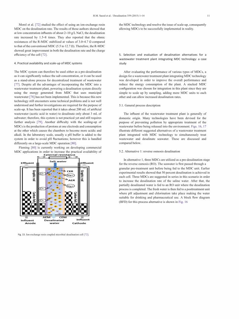
3.12. Ion-exchange resin coupled microbial desalination cell
As the desalination process is taking place in MDCs, the ohmic resistance in the cell greatly increases with the decrease in the salt concentration and conductivity of the saline water; this would limit the electricity production and the desalination rate [10]. Thus, a scenario to reduce the ohmic resistance should be established in order to improve the MDC performance, particularly in applications involving low salinity waters, such as brackish waters or effluents from industrial wastewater treatment plants [73–75]. This can be achieved by packing the MDC desalination chamber with mixed anion- and cation-exchange resins; this results in an ion-exchange resin coupled MDC (R-MDC). The scheme is illustrated in Fig. 15. Since these ion-exchange resins have high conductivities, they can easily operate as ionic conductors in low salinity water, stabilizing the ohmic resistance and reducing energy consumption in the desalination unit.
In practical applications, however, the saltwater always contains salts other than NaCl which may inhibit the performance of the R-MDC. Seawater usually contains calcium and magnesium ions and these may deposit on the resin surfaces and therefore cause scaling. This in turn would increase the internal resistance of the cell and prevent ion migration. Additionally, if the anode is anaerobic, the NO−
3
and SO24
− ions would reduce to N2 and H2S and compete with the anode as electron acceptors, reducing the columbic efficiency [76].
H.M. Saeed et al. / Desalination 359 (2015) 1–14 11
Morel et al. [72] studied the effect of using an ion-exchange resin MDC on the desalination rate. The results of those authors showed that at low concentration influents of about 2–10 g/L NaCl, the desalination rate increased by 1.5–8 times. They also reported that the ohmic resistances of the R-MDC stabilized at values of 3.0–4.7 Ω compared to that of the conventional MDC (5.5 to 12.7 Ω). Therefore, the R-MDC showed great improvement in both the desalination rate and the charge efficiency of the cell [72].
4. Practical availability and scale-up of MDC systems
The MDC system can therefore be used either as a pre-desalination as it can significantly reduce the salt concentration, or it can be used as a stand-alone process for decentralized treatment of wastewater [77]. Despite all the advantages of incorporating the MDC into a wastewater treatment plant, powering a desalination system directly using the energy generated from MDC that uses municipal wastewater [78] has not been implemented. This is because this new technology still encounters some technical problems and is not well understood and further investigations are required for the purpose of scale-up. It has been reported that it takes about 200 mL of artificial wastewater (acetic acid in water) to desalinate only about 3 mL of saltwater; therefore, this system is not practical yet and still requires further analysis [79]. Another difficulty with the scaling-up of MDCs is the production of protons at one electrode and consumption at the other which causes the chambers to become more acidic and alkali. In the laboratory scale, usually a pH buffer is added to the system in order to avoid pH fluctuations; however this is handled differently on a large-scale MDC operation [80].
Fleming [80] is currently working on developing commercial MDC applications in order to increase the practical availability of
the MDC technology and resolve the issue of scale-up, consequently allowing MDCs to be successfully implemented in reality.
5. Selection and evaluation of desalination alternatives for a wastewater treatment plant integrating MDC technology: a case study
After evaluating the performance of various types of MDCs, a design for a wastewater treatment plant integrating MDC technology was developed in order to improve the overall performance and reduce the energy consumption of the plant. A stacked MDC configuration was chosen for integration in this plant since they are simple to scale up by sampling, adding more MDC units to each other and can allow increased desalination rates.
5.1. General process description
The influent of the wastewater treatment plant is generally of domestic origin. Many technologies have been devised for the purpose of preventing pollution by appropriate treatment of the wastewater before being released into the environment. Figs. 16, 17 illustrate different suggested alternatives of a wastewater treatment plant integrated with MDC technology to simultaneously treat wastewater and desalinate seawater. These are discussed and compared below.
5.2. Alternative 1: reverse osmosis desalination
In alternative 1, three MDCs are utilized as a pre-desalination stage for the reverse osmosis (RO). The seawater is first passed through a granular pre-treatment unit before being fed to the MDC unit. Earlier experimental results showed that 50 percent desalination is achieved in each cell. Three MDCs are suggested in series in this scenario in order to increase the desalination rate of the saline water. After that, the partially desalinated water is fed to an RO unit where the desalination process is completed. The fresh water is then fed to a posttreatment unit where pH adjustment and chlorination take place making the water suitable for drinking and pharmaceutical use. A block flow diagram (BFD) for this process alternative is shown in Fig. 16
Fig. 15. Ion-exchange resin coupled microbial desalination cell [72].

12 H.M. Saeed et al. / Desalination 359 (2015) 1–14
5.3. Alternative 2: multistage flash desalination
In alternative 2, three MDCs are stacked together and used as a pre-desalination technique, whereby 50% of desalination is carried out in each cell. After pre-desalination, the treated water is fed to the multistage flash desalination (MSF) columns for further treatment, as shown in Fig. 16 (Altern. 2). The MSF desalination process is used in industries where large amount of saline water is treated by means of low-pressure steam. In such a process, the feed water enters the first column of the MSF desalination system and steam is provided as a heat source to the saline water. The steam itself condenses as it heats the feed water and the treated water is further circulated into multiple stages ahead in the system, thereby allowing the desalination process to be carried out efficiently.
5.4. Evaluation of desalination alternatives
The two desalination alternatives described above can be compared to each other using matrix analysis in order to select the most feasible alternative for the plant. Six criteria are selected as basis for the selection of the best alternative; these include capital cost, operating cost, desalination efficiency, environmental impact and safety. Each criterion is assigned a specific weightage based on its importance in the selection of the plant; these are illustrated in Fig. 17. The highest weights were assigned for operating cost and desalination efficiency since the main objective of a wastewater treatment plant integrating MDCs is to achieve the highest possible salt removal while using the least amount of energy. Each alternative is then assigned a score for each criterion. All the scores are then summed up to give the total points obtained for each alternative.
The capital costs are higher for the MSF desalination process compared to
Fig. 16. BFD of different alternatives: Altern. 1 — RO; Altern. 2 — MSF; Altern. 3— solar desalination.
alternative 1 with RO desalination unit is assigned a higher score, due to lower capital costs, than alternative 2 with MSF.
The operating costs for the RO process are usually higher due to more complex maintenance and operation associated with this process. In addition, the cost of labor and chemicals would also be higher for RO. Therefore, the MSF process is given a higher score than RO for this criterion as it has less operating costs.
The energy cost associated with the plants refers to the cost of the energy input into the plant to be able to efficiently operate the wastewater treatment plants and MDCs. The energy cost for the MSF alternative is a lot higher than that for RO, and is thus assigned a lower score.
Fig. 17. Criteria for selection. The desalination efficiency refers to the percentage of salt that is removed
from the seawater in the wastewater treatment plants. For alternative 1 using the RO post-treatment, the TDS level of the output stream is around 350–500 ppm; while the TDS level of the output stream from the MSF is less than 10 ppm. For this reason, the MSF is given a higher score than RO for desalination efficiency [81].
The main environmental impacts caused by the two desalination plants used for post-treatment are through brine discharges back into the sea and greenhouse gas emissions. Since the brine temperature in RO does not increase much compared to that in MSF; the latter would have a greater environmental impact on the marine life in the sea. In addition, since more energy is used in the MSF process, consequently, it would also produce more greenhouse gas emissions. Hence, the MSF alternative has a greater environmental impact compared to RO and is assigned a lower score for this criterion [82]. The safety issues with the wastewater plant using MSF desalination unit can be assumed to be more severe due to higher operating temperatures (up to 120 °C) compared to RO, which operates at temperatures in the range of 20–40 °C. However, the RO process deals with very high pressures, which would also require cautious handling. However, the safety issues due to high temperature steam are assumed to be more serious, and thus the MSF process is given a lower score with regard to safety [83].
Table 2 compares the different alternatives with scores out 10 point. It seems that alternative 2 is a more feasible one; however, because of the energy costs of MSF which are still high, a third alternative is suggested.
5.5. Alternative 3: solar-assisted desalination
Solar-assisted desalination can reduce the energy requirements for the plant. More attention is given to the solar collector assisted multi effect
the RO due to the high construction costs of the MSF. Therefore desalination (MED) and multi-stage flash (MSF) plant. The MED plant consists of multiple stages or “effects”. In each stage, the feed water is heated using steam in the tubes. Some of the water evaporates, and this steam flows into the tubes of the next stage, consequently heating and evaporating more water. Each stage essentially reuses the energy from the previous stage. In
this case, source water can be preheated using a solar collector which would reduce the energy load needed for the desalination unit. A typical solar collector could be a bank of evacuated tubes. A solar pond consists of three layers of
Altern. 1 , 2 or 3

H.M. Saeed et al. / Desalination 359 (2015) 1–14 13
Table 2 Calculation of the different criteria for two alternatives.
Capital cost 15% 6 5 Operating cost 10% 3 7 Energy cost 25% 8 5 Desalination efficiency 25% 4 9 Environmental impact 10% 7 3 Safety 15% 5 4 Total points 100% 5.65 5.85
saltwater in which the concentration of the salt increases from top to bottom with the top layer having the lowest concentration and the bottom with the highest. However, the middle layer has a salinity gradient which prevents heat transfer by convection and acts as insulation layer [83].
As shown in Fig. 16 (Altern. 3), seawater enters the solar collector and leaves as heated water, which then flows into a heat accumulator comprising a series of adjacent tanks. The heat accumulator is used to ensure that the temperature variations in the evaporator are not significant and are not affected by the fluctuations in the solar energy. Moreover, the evaporator is operated at relatively high temperatures (e.g. 99 °C) and very low pressures (e.g. 0.07 atm). The preheated water then leaves the collector and enters the first tank while the water entering the evaporator should be taken from the top of the first tank and returned to the bottom of the last tank. This ensures that the water entering the evaporator is at its highest temperature. In a solar-assisted MSF unit, the first stage of the MSF heat exchangers becomes a liquid– liquid heat exchanger instead of steam–liquid heat exchanger. The solar collector for a typical MSF system is a solar pond since the waste brine generated from the process can be recycled to the pond.
6. Conclusion
Microbial desalination cell (MDC) is an upcoming technology which can minimize power consumption and recover increased desalinated water when installed as a pre-desalination unit. MDCs produce their own electricity while treating wastewater and desalinating water simultaneously by exposing the organic matter in waste water to exoelectrogenic bacteria. Various MDCs, that can be further extended to real waste water plants for economic affordability and saving energy, have been briefly discussed in this paper. The study on MDCs was further extended by considering a case study which integrates this technology into a wastewater treatment plant and evaluating different alternatives for this proposed plant. It can be said that MDCs are a novel technique for treating waste water and desalinating seawater; a technique capable of minimizing capital costs and simultaneously increasing the treatment efficiency of treatment plants.
List of abbreviations
AEM Anion-exchange membrane BAC BPM–AEM–CEM stack structure BPM Bipolar membrane CEM Cation-exchange membrane CE Coulombic efficiency c-SMDC-S Stacked circulation microbial desalination cell DR Desalination rate FO Forward osmosis IEMs Ion-exchange membranes MDC Microbial desalination cell MEDC Microbial electrolysis desalination cell MEDCC Microbial electrolysis desalination and chemical-production
cell
MFC Microbial fuel cell MSF Multistage flash desalination PBS Phosphate buffer solution R-MDC Ion-exchange resin coupled microbial desalination cell PRO Pressure retarded osmosis RO Reverse osmosis rMDC Re-circulation microbial desalination cell SEM Scanning electron microscope TDS Total dissolved solid UMDC Upflow MDC References
[1] C. Torres, Improving microbial fuel cells, Membr. Technol. 2012 (8) (August 2012) 8–9. [2] J. Mercer, Microbial Fuel Cells: Generating Power From Waste, illumin.usc.eduApril 26,
2014 (vol. XV (II), Online). [3] D.R. Lovley, Microbial fuel cells: novel microbial physiologies and engineering approaches,
Curr. Opin. Biotechnol. 17 (3) (June 2006) 327–332. [4] H. Wang, Z.J. Ren, A comprehensive review of microbial electrochemical systems as a
platform technology, Biotechnol. Adv. 31 (8) (2013) 796–1807. [5] H. Luo, P. Xu, P.E. Jenkins, Z. Ren, Ionic composition and transport mechanisms in
microbial desalination cells, J. Membr. Sci. 409–410 (2012) 16–23. [6] C. Forrestal, P. Xu, P.E. Jenkins, Z. Ren, Microbial desalination cell with capacitive
adsorption for ion migration control, Bioresour. Technol. 120 (2012) 332–336. [7] Q. Ping, B. Cohen, C. Dosoretz, Z. He, Long-term investigation of fouling of cation and
anion exchange membranes in microbial desalination cells, Desalination 325 (2013) 48–55. [8] L. Yuan, X. Yang, P. Lian, L. Wang, Z. Huang, J. Wei, X. Huang, Capacitive deionization
coupled with microbial fuel cells to desalinate low-concentration salt water, Bioresour. Technol. 110 (2012) 735–738.
[9] M. Mehanna, B.E. Logan, Microbial desalination cell for simultaneous water desalination and energy production, Global Water ProgramNov. 8, 2010.
[10] X. Cao, X. Huang, P. Liang, K. Xiao, Y.J. Zhou, X.Y. Zhang, B.E. Logan, A new method for water desalination using microbial desalination cells, Environ. Sci. Technol. 43 (18) (2009) 7148–7152.
[11] M. Otto, Virulence factors of the coagulase-negative staphylococci, Front. Biosci. 9 (2004) 841–863.
[12] D. Lopez, H. Vlamakis, R. Kolter, Biofilm, Cold Spring Harb. Perspect. Biol. 2 (7) (2010) 1–11.
[13] J. Harrison, R. Turner, L. Marques, H. Ceri, Biofilms: a new understanding of these microbial communities is driving a revolution that may transform the science of microbiology, Am. Sci. 93 (6) (2005) 508–515.
[14] R. Sekar, V. Venugopalan, K. Nandakumar, K. Nair, V. Rao, Early stages of biofilm succession in a lentic freshwater environment, Hydrobiologia 512 (1–3) (2004) 97–108.
[15] H. El-Dessouky, H.I. Shaban, H. Al-Ramadan, Steady-state analysis of multi-stage flash desalination process, Desalination 103 (1995) 271–287.
[16] C. Jacovide, J. Parvizi, Biofilm infections: newer understanding of old problem, Orthop. Today 30 (9) (2010) 28–29.
[17] A. Proal, Understanding biofilms, Bacteriality: Exploring Chronic DiseaseMay 26, 2014. (Online).
[18] A.B. Rajeb, H. Kallali, N.B. Aissa, O. Bouzaiene, S. Jellali, N. Jedidi, A. Hassen, Soil microbial growth and biofilm expansion assessment under wastewater infiltration percolation treatment process: column experiments, Desalination 246 (2009) 514–525.
[19] S. Yang, F. Du, H. Liu, Characterization of mixed-culture biofilms established in microbial fuel cells, Biomass Bioenergy 46 (2012) 531–537.
[20] D. Chop, Modeling Microbial Fuel Cells: An ISEN Supported Project, ESAM Northwestern University, 2009. 1–4.
[21] L. Zhang, X. Zhu, J. Li, Q. Liao, D. Ye, Biofilm formation and electricity generation of a microbial fuel cell started up under different external resistances, J. Power Sources 196 (2011) 6029–6035.
[22] V.G. Gude, B. Kokabian, V. Gadhamshetty, Beneficial bioelectrochemical systems for energy, water, and biomass production, Microb. Biochem. Technol. S6 (2013) 1–14.
[23] M. Mehanna, T. Saito, J. Yan, M. Hickner, X. Cao, X. Huang, B.E. Logan, Using microbial desalination cells to reduce water salinity prior to reverse osmosis, Energy Environ. Sci. 3 (2010) 1114–1120.
[24] P. Clauwaert, D.V.D. Ha, N. Boon, K. Rabaey, W. Verstraete, Open air biocathode enables effective electricity generation with microbial fuel cells, Environ. Sci. Technol. 41 (2007) 7564–7569.
[25] E. Croese, M.A. Pereira, G.W. Euverink, A.J.M. Stams, J.S. Geelhoed, Analysis of the microbial community of the biocathode of a hydrogen-producing microbial electrolysis cell, Bioenergy Biofuels 92 (2011) 1083–1093.
[26] X.A. Walter, J. Greenman, I.A. Ieropoulos, Oxygenic phototrophic biofilms for improved cathode performance in microbial fuel cells, Algal Res. 2 (2013) 183–187.
[27] L. Huang, X. Chai, G. Chen, B.E. Logan, Effect of set potential on hexavalent chromium reduction and electricity generation from biocathode microbial fuel cells, Environ. Sci. Technol. 45 (2011) 5025–5031.
[28] Q. Wen, H. Zhang, Z. Chen, Y. Li, J. Nan, Y. Feng, Using bacterial catalyst in the cathode of microbial desalination cell to improve wastewater treatment and desalination, Bioresour. Technol. 125 (2012) 108–113.
[29] H.B. Kim, Microbial fuel cell-type biochemical oxygen demand sensor, Encycl. Sensors 10 (2006) 1–12.

14 H.M. Saeed et al. / Desalination 359 (2015) 1–14
[30] L. Huang, J.M. Regan, X. Quan, Electron transfer mechanisms, new applications, and performance of biocathode microbial fuel cells, Bioresour. Technol. 102 (2011) 316–323.
[31] Z. Zaybak, J.M. Pisciotta, J.C. Tokash, B.E. Logan, Enhanced start-up of anaerobic facultatively autotrophic biocathodes in bioelectrochemical systems, J. Biotechnol. 168 (2013) 478–485.
[32] K.Y. Cheng, G. Ho, R. Cord-Ruwisch, Novel methanogenic rotatable bioelectrochemical system operated with polarity inversion, Environ. Sci. Technol. 45 (2) (2010) 796–802.
[33] K.Y. Cheng, G. Ho, R. Cord-Ruwisch, Energy-efficient treatment of organic wastewater streams using a rotatable bioelectrochemical contactor (RBEC), Bioresour. Technol. 126 (2011) 431–436.
[34] Y. Kim, B.E. Logan, Microbial desalination cells for energy production and desalination, Desalination 308 (2013) 122–130.
[35] N.A. Shehab, B.E. Logan, G.L. Amy, P.E. Saikaly, Microbial electrodeionization cell stack for sustainable desalination, WEFTEC, 2013, pp. 222–227.
[36] J. Choi, Y. Ahn, Continuous electricity generation in stacked air cathode microbial fuel cell treating domestic wastewater, J. Environ. Manag. 130 (2013) 146–152.
[37] X. Chen, X. Xia, P. Liang, X. Cao, H. Sun, X. Huang, Stacked microbial desalination cells to enhance water desalination efficiency, Environ. Sci. Technol. 45 (2011) 2465–2470.
[38] Y. Kim, B.E. Logan, Series assembly of microbial desalination cells containing stacked electrodialysis cells for partial or complete seawater desalination, Environ. Sci. Technol. 45 (2011) 5840–5845.
[39] Y. Qu, Y. Feng, J. Liu, W. He, X. Shi, Q. Yang, J. Lv, B.E. Logan, Salt removal using multiple microbial desalination cells under continuous flow conditions, Desalination 317 (2013) 17–22.
[40] Y. Qu, Y. Feng, X. Wang, J. Liu, J. Lv, W. He, et al., Simultaneous water desalination and electricity generation in a microbial desalination cell with electrolyte recirculation for pH control, Bioresour. Technol. 106 (2012) 89–94.
[41] H. Luo, P.E. Jenkins, Z. Ren, Concurrent desalination and hydrogen generation using microbial electrolysis and desalination cells, Environ. Sci. Technol. 45 (2011) 340–344.
[42] Z. He, Y. Huang, A.K. Manohar, F. Mansfeld, Effect of electrolyte pH on the rate of the anodic and cathodic reactions in an air-cathode microbial fuel cell, Bioelectrochemistry 74 (2008) 78–82.
[43] M.D. LaGrega, P.L. Buckingham, J.C. Evans, Hazardous Waste Management, Second edition McGraw-Hill, 2001.
[44] K.S. Jacobson, D.M. Drew, Z. He, Efficient salt removal in a continuously operated upflow microbial desalination cell with air cathode, Bioresour. Technol. 102 (2011) 376–380.
[45] S. Freguia, K. Rabaey, Z.G. Yuan, J. Keller, Sequential anode–cathode configuration improves cathodic oxygen reduction and effluent quality of microbial fuel cells, Water Res. 42 (2008) 1387–1396.
[46] S. Chen, G. Liu, R. Zhang, B. Qin, Y. Luo, Y. Hou, Improved performance of the microbial electrolysis desalination and chemical-production cell using the stack structure, Bioresour. Technol. 116 (2012) 507–511.
[47] M. Mehanna, P.D. Kiely, D.F. Call, B.E. Logan, Microbial electrodialysis cell for simultaneous water desalination and hydrogen gas production, Environ. Sci. Technol. 44 (2010) 9578–9583.
[48] S. Chen, H. Luo, G. Liu, R. Zhang, H. Wang, B. Qin, Y. Hou, Integrated utilization of seawater using a five-chamber bioelectrochemical system, J. Membr. Sci. 444 (2013) 16–21.
[49] S. Chen, G. Liu, R. Zhang, B. Qin, Y. Luo, Development of the microbial electrolysis desalination and chemical production cell for desalination as well as acid and alkali productions, Environ. Sci. Technol. 46 (2012) 2467–2472.
[50] H. Luo, P. Xu, T.M. Roane, P.E. Jenkins, Z. Ren, Microbial desalination cells for improved performance in wastewater treatment, electricity production, and desalination, Bioresour. Technol. 105 (2012) 60–66.
[51] P. Xu, J.E. Drewes, D. Heil, Beneficial use of co-produced water through membrane treatment: technical-economic assessment, Water Res. 225 (1–3) (2008) 139–155.
[52] C. Forrestal, P. Xu, Z. Ren, Sustainable desalination using a microbial capacitive desalination cell, Energy Environ. Sci. 5 (2012) 7161–7167.
[53] B. Zhang, Z. He, Energy production, use and saving in a bioelectrochemical desalination system, RSC Adv. 2 (28) (2012) 10673–10679.
[54] K.S. Jacobson, D.M. Drew, Z. He, Use of a liter-scale microbial desalination cell as a platform to study bioelectrochemical desalination with salt solution or artificial seawater, Environ. Sci. Technol. 45 (2011) 4652–4657.
[55] Z. He, Microbial desalination cells, U.S. Patent 61/355 438, Dec. 22, 2011. [56] Z. He, N. Wagner, S.D. Minteer, L.T. Angenent, An upflow microbial fuel cell with an
interior cathode: assessment of the internal resistance by impedance spectroscopy, Environ. Sci. Technol. 40 (2006) 5212–5217.
[57] Z. He, N. Wagner, S.D. Minteer, L.T. Angenent, Electricity generation from artificial wastewater using an upflow microbial fuel cell, Environ. Sci. Technol. 39 (2005) 5262–5267.
[58] F. Zhang, K.S. Jacobson, P. Torres, Z. He, Effects of anolyte recirculation rates and catholytes on electricity generation in a litre-scale upflow microbial fuel cell, JRS Adv. (2010), http://dx.doi.org/10.1039/c001201g (online).
[59] Z. Ge, Z. He, Effects of draw solutions and membrane conditions on electricity generation and water flux in osmotic microbial fuel cells, Bioresour. Technol. 109 (2012) 70–76.
[60] T.Y. Cath, A.E. Childress, M. Elimelech, Forward osmosis: principles, applications and recent developments, J. Membr. Sci. 281 (2006) 70–87.
[61] S. Zhao, L. Zou, C.Y. Tang, D. Mulcahy, Recent developments in forward osmosis: opportunities and challenges, J. Membr. Sci. 396 (2012) 1–21.
[62] F. Zhang, K. Brastad, Z. He, Integrating forward osmosis into microbial fuel cells for wastewater treatment, water extraction and bioelectricity generation, Environ. Sci. Technol. 45 (2011) 6690–6696.
[63] B. Zhang, Z. He, Integrated salinity reduction and water recovery in an osmotic microbial desalination cell, RSC Adv. 2 (2012) 3265–3269.
[64] C.M. Werner, B.E. Logan, P.E. Saikaly, G.L. Amy, Wastewater treatment, energy recovery and desalination using a forward osmosis membrane in an air-cathode microbial osmotic fuel cell, J. Membr. Sci. 428 (2013) 116–122.
[65] B. Zhang, Z. He, Improving water desalination by hydraulically coupling an osmotic microbial fuel cell with a microbial desalination cell, J. Membr. Sci. 441 (2013) 18–24 (66).
[66] C. Huang, T. Xu, Electrodialysis with bipolar for sustainable development, Environ. Sci. Technol. 40 (2006) 5233–5243.
[67] R.P. Buck, Ion-selective membranes and electrodes, Access Science, McGraw-Hill Education, 2014. (Retrieved from http://www.accessscience.com, Online).
[68] F. Alvarez, R. Alvarez, J. Coca, J. Sandeaux, R. Sandeaux, C. Gavach, Salicyclic acid production by electrodialysis with bipolar membranes, J. Membr. Sci. 123 (1997) 61–69.
[69] Q. Ping, Z. He, Improving the flexibility of microbial desalination cells through spatially decoupling anode and cathode, Bioresour. Technol. 144 (2013) 304–310.
[70] Q. Ping, Z. He, Effects of inter-membrane distance and hydraulic retention time on the desalination performance of microbial desalination cells, Desalin. Water Treat. 52 (6–7) (2013) 1324–1331.
[71] X. Chen, P. Liang, Z. Wei, X. Zhang, X. Huang, Sustainable water desalination and electricity generation in a separator coupled stacked microbial desalination cell with buffer free electrolyte circulation, Bioresour. Technol. 119 (2012) 88–93.
[72] A. Morel, K. Zuo, X. Xia, J. Wei, X. Luo, P. Liang, X. Huang, Microbial desalination cells packed with ion-exchange resin to enhance water desalination rate, Bioresour. Technol. 118 (2012) 43–48.
[73] K.-E. Bouhidel, A. Lakehal, Influence of voltage and flow rate on electrodeionization (EDI) process efficiency, Desalination 193 (2006) 411–421.
[74] H. Strathmann, Electrodialysis, a mature technology with a multitude of new applications, Desalination 264 (2010) 268–288.
[75] K. Zuo, L. Yuan, J. Wei, P. Liang, X. Huang, Competitive migration behaviors of multiple ions and their impacts on ion-exchange resin packed microbial desalination cell, Bioresour. Technol. 146 (2013) 637–642.
[76] Z. He, Microbial desalination cells. Patent Application Publication, 2011, Pub. No.: US 2011/0311887 A1.
[77] B. Wang, Y. Liu, S. Liu, Self-sustained desalination in combination with wastewater treatment — hybrid microbial desalination system, Colorado Science and Engineering Fair, March 2011.
[78] L. Bruce, Electricity and Desalination from WastewaterRetrieved from http://www. alternative-energy-news.info August 20 2009 (Online).
[79] Wastewater Produces Electricity and Desalinates Water, Pennsylvania State University, Aug. 6, 2009. (phys.org, Online).
[80] G. Fleming, Partnering Profile, Milwaukee Water Council (2011) (Online). [81] A.A. Al-Karaghouli, L.L. Kazmerski, Renewable energy opportunities in water desalination,
Desalination Trends and Technologies (2011) pp. 149–184. [82] X. Bernat, O. Gibert, R. Guiu, J. Tobella, C. Campos, The economics of desalination for
various uses (Ed.)Water Technology Center (2010) pp. 439–346. [83] J.P. Chen, et al., Desalination of seawater by thermal distillation and electrodialysis
technologies, in: L.k. Wange, et al., (Eds.), Membrane and Desalination Technologies, Springer, New York, 2011.