microcord carb series
TRANSCRIPT

MICROCORD
Non-contact/contact horizontal-arm type CNC Coordinate Measuring Machines for the car body industry
Coordinate Measuring Machines
CARB Series

2
A Coordinate Measuring Machine (CMM) is required at many stages in the process of work piece development, such as for CAD data creation, mold building, jig making, prototype evaluation, welding, and inspection on a mass-production line. Furthermore, a high-precision CNC CMM is required for prototype inspection, analysis and mass production in manufacturing large work pieces for the automotive, aerospace, defense, heavy machinery, railway, and ship industries to name only a few.The automation of 3D coordinate measurement by introducing a CARB series system can allow simplification of conventional inspection/fixing jigs or even the elimination of inspection jigs, and can achieve major cost reductions in addition to improving accuracy in parts and assembly.The CARB series, with capacity up to 8 meters (26 feet), can cope with even large-sized workpieces such as large aircraft parts and spacecraft components, as well as car bodies. Since this series can operate while automatically interchanging contact and non-contact probes, tens of millions of measurement points can be collected in a short time.With the aid of an optional software program this series can be used not only for quality control purposes but also for reverse engineering, thus drastically reducing the time required for development and prototyping. The CARB series combines horizontal-type CMM with high accuracy and maximum flexibility.
Horizontal-type CMM for large work piece

3

4
High Speed, High Stability and Environmentally RobustOn car body production lines, managing the assembly accuracy of individual parts comprising a car body is paramount. With statistical quality control requirements for molded and pressed parts in the final finishing process may require inspection of subassembly parts on a 100-percent basis. A CMM to meet these needs must have the durability to withstand around-the-clock operation while still delivering high speed and high accuracy.CARBstrato is the horizontal arm CMM that satisfies these requirements with its fully-covered main unit, automatic temperature compensation function and dual-arm operation. This CMM can perform high-speed quality evaluation not only on parts with contoured surface profiles, including car bodies and aircraft parts, but also those using many common geometric elements, allowing application to the measurement of large marine parts, and heavy equipment components.
High Speed, High Stability, and EnvironmentallyRobust

5
CARBstrato
Cast iron is used for the base to ensure high stability for all axes. The Z-axis slider is provided with high acceleration by the integration of an air-operated balancing mechanism, and aluminum alloy guide with a large cross-section in accordance with Mitutoyo’s unique design technology.Carbon fiber is used for the Y-axis arm(s) to minimize cross section and to prevent interference while still maintaining high stiffness.Each axis is provided with a temperature sensor near the scale to provide automatic compensation for the difference in linear thermal expansion coefficient of the different materials involved. This allows the CMM to be operated over a wide temperature range without loss ofaccuracy.A backlash free, minimum-vibration mechanism has been adopted for the X-axis drive. Air bearings and a frictiondrive system on the Y- and Z-axes minimizes vibrations during movement. Stable measurement results are achieved wit continuous scanning probes (contact or noncontact type).
Balance cylinder
X slider (Al alloy)
Y spindle (CFRP)
LM guide
Main unit supports: 3 points
Base (cast iron)
Low hysteresis Rack and pinion

6
In the CARBstrato series, a single-arm system with one main unit and a dual-arm system with two main units installed are available. A four-arm system can also be made as an option. If a single item part is to be measured at high speed, the single-arm machine is optimal. If a body shell or a large part is to be measured at high speed, the dual-arm specification is optimal. In the dual-arm machine, both arms can share one workpiece coordinate system while the software performs an automatic interference check to prevent one arm colliding with the other. A dual-arm machine can be separated so as to operate independently as two single-arm machines if required.
A light-sensitive safety device installed in the Y-axis-arm bellows stops all axial movement immediately when the arm comes into contact with a workpiece, clamp or anything else during measurement. Movement also stops, in all axes, if an excessive twisting load is exerted on the rotary head. Predetermined operations, performed after safety verification, restore the system to an operational state.This safety device functions in the same manner when using a contact or non-contact probe and, particularly when measuring the inside of a car body or a component fixed with many clamps, greatly increases safety for the operator and machine.
The top of the base that houses the X-axis is completely protected with diamond steel plating for operator safety and accessibility to the parts being measured.Foreign matter is prevented from reaching the axis guides by shielding all openings with belt-shaped covers. If the system is installed in a pit, so that the top of the base is level with the floor, the operator can freely walk around the measurement space, assuring high operability and safety.
Dual-arm specification Single-arm specification

Multi-point support method 3-point support method
3-point support method One-point clamp method (free in longitudinal direction)
Accuracy degradation due to settling
Accuracy degradation due to rigid fixing
Adopted method
7
CARBstrato
Combating Foundation Deformation• The secular deformation of foundation concrete after construction cannot be avoided. A periodical leveling adjustment of supports is required because of the effect on accuracy due to this deformation.• The adoption of the 3-point support method maintains long-term accuracy independently of foundation deformation.
3-point Support MethodCMM accuracy is degraded by settling of the concrete foundations, so a machine using the multi-point support method needs periodical leveling adjustment to maintain the installed accuracy specification. However, the 3-point support method can maintain measurement-space accuracy irrespective of such unavoidable deformation. This simplest of all support methods requires leveling adjustment only at 2 points and so makes for rapid, easy maintenance.(The 3-point support method is provided with up to 6m machine.)
Combating Differential ExpansionIf the cast-iron base were rigidly fixed to the concrete foundations then any difference in temperature between the two would allow differential thermal expansion, an unavoidable effect, to generate forces which would distort the base and degrade accuracy.To overcome the consequences of this effect the adopted method is to fix the base to the foundations at one support point only. One of the other support points is then allowed to slide in a straight line away from the fixed point and the remaining point is free to slide in any direction in the horizontal plane. Therefore the base and the foundations can expand and contract independently without any distorting force arising between them.

8
The bellows shown in the photo are optional.
Low-cost, high performance
The CARBapex system can be equipped with a light-sensitive safety device but only if the optional bellows are fitted. The safety device operates by detecting interference between the bellows on the Y-axis arm and any obstruction to immediately stop the machine. It is recommended that bellows be fitted when operating in a dust-laden environment. However, note that bellows reduce the stroke of the Y and Z axes.
Some large work piece manufacturing does not require the CMM to possess the high speed and ruggedness that is needed on a production line. For example, the design, preproduction and subcontract sections all fall into this category. Also, activities such as sampling inspection or reverse engineering do not require a high-speed machine. For these groups and applications the CARBapex is offered as a lower-cost version of CARBstrato to provide the same versatility at a lower operating speed and with less environmental protections, but still with the automatic temperature compensation function and dual-arm operation of CARBstrato.The operator control (joystick box), software and operating procedures of CARBapex are 100% identical to those of CARBstrato and part programs are also compatible. Owing to the open, horizontal-type design of this cost-effective CMM it is highly suitable for quality improvement measurement applications for products across a wide range of fields including plastic parts, glass parts, reinforcing parts, drive-train parts, clay models, inspection jigs as well as car bodies and pressed parts. Higher environmental protections can be achieved if required the addition of main unit optional bellow covers.

Rotary head center traveling range
Y-axis stroke= Stroke of the single machine×2−100
Floor level
100 Overlapping area
350 740 350740
108 108
90
Z
24048
9249
9
CARBapex
Cast iron is used for the CARBapex base structure to give rigidity and stability, and ball-circulation type high-rigidity linear guides form the X-axis. The Z- and Y-axis arms are manufactured from extruded aluminum alloy to minimize overall mass and to utilize air bearings for frictionless movement. Owing to the use of air bearings, abrasions do not occur on any part of the Y-axis arm, therefore maintaining high accuracy. In addition, all connecting cables are contained in a caterpillar-type cable guide, cables cannot interfere with objects placed on the site floor. The top of the base that houses the X-axis is completely protected with diamond steel plating, the same as CARBstrato, for operator safety and accessibility to the parts being measured.The use of air bearings for the Y-axis arm distinguishes it from the typical layout machine and this is an extremely important factor for maintaining the straightness of the arm between annual verification tests. Also, the large square cross-section of the Z-axis column minimizes deformation due to expansion/contraction of the arm. Moreover, Mitutoyo’s unique friction drive system on all axes minimizes vibration during travel, unlike the conventional rack and pinion arrangement. A drive system that generates no vibration is especially important because it has the effect of causing no noise in the measurement results of a scanning probe.
Unit: mm
Z column (Al alloy)
X slider (cast iron)
Y spindle (Al alloy)
Multipoint support
Base (cast iron)Linear guide
Linear guide
Counterbalance (inside the column)
The X-axis base of CARBapex is designed to the minimum for a horizontal-type coordinate measuring machine. Therefore, if this system is installed on the floor the top of the base is low and provides the operator with safer operation. Also, if this system is installed under the floor, the cost of the foundations can be reduced because of the shallower excavation required.Since the Y-axis spindle is located at the lower end of the Z-axis slider, the spindle can be lowered close to a measuring plane.This allows the height of fixtures to be lower so that the operator can work safely even when measuring the top of a large part.
10
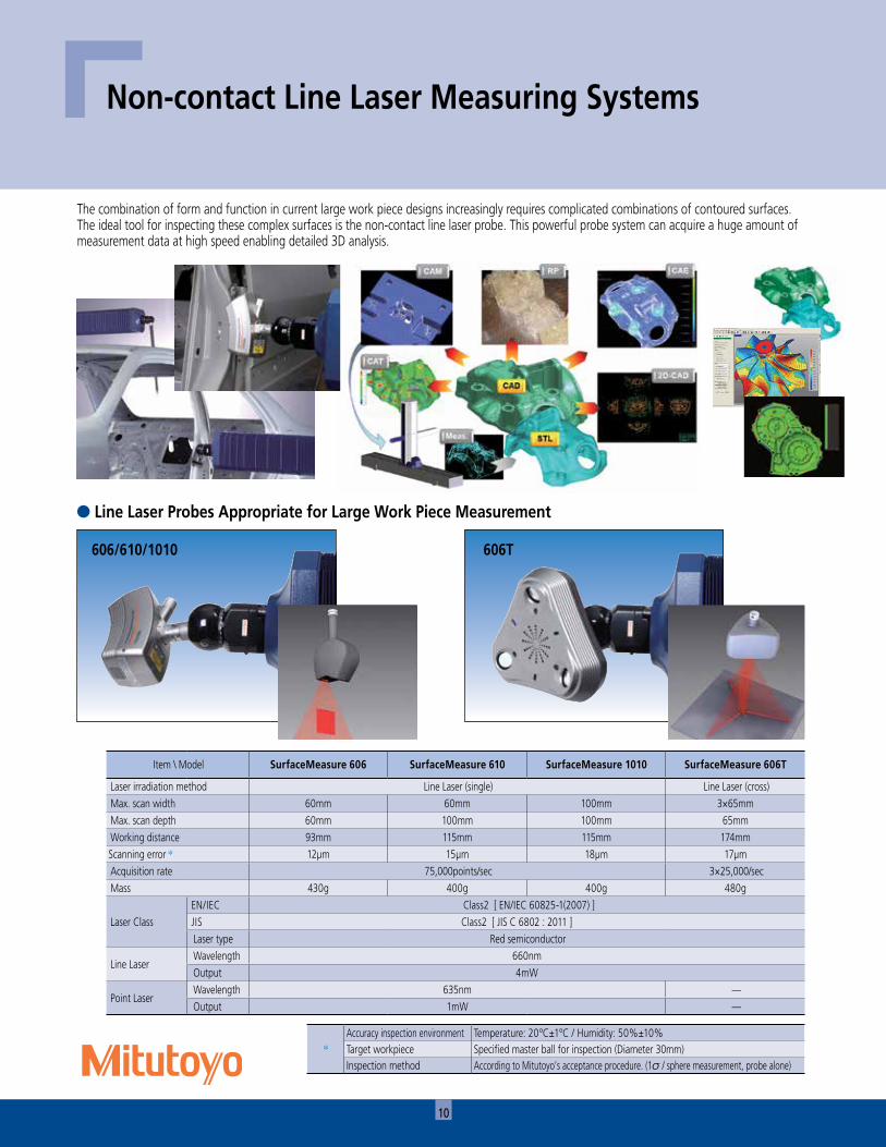
l Line Laser Probes Appropriate for Large Work Piece Measurement
Non-contact Line Laser Measuring Systems
The combination of form and function in current large work piece designs increasingly requires complicated combinations of contoured surfaces. The ideal tool for inspecting these complex surfaces is the non-contact line laser probe. This powerful probe system can acquire a huge amount of measurement data at high speed enabling detailed 3D analysis.
606/610/1010 606T
Item \ Model SurfaceMeasure 606 SurfaceMeasure 610 SurfaceMeasure 1010 SurfaceMeasure 606T
Laser irradiation method Line Laser (single) Line Laser (cross)Max. scan width 60mm 60mm 100mm 3×65mmMax. scan depth 60mm 100mm 100mm 65mmWorking distance 93mm 115mm 115mm 174mmScanning error * 12μm 15μm 18μm 17μmAcquisition rate 75,000points/sec 3×25,000/secMass 430g 400g 400g 480g
Laser ClassEN/IEC Class2 [ EN/IEC 60825-1(2007) ]JIS Class2 [ JIS C 6802 : 2011 ]Laser type Red semiconductor
Line LaserWavelength 660nmOutput 4mW
Point LaserWavelength 635nm —Output 1mW —
*Accuracy inspection environment Temperature: 20ºC±1ºC / Humidity: 50%±10%Target workpiece Specified master ball for inspection (Diameter 30mm) Inspection method According to Mitutoyo’s acceptance procedure. (1 / sphere measurement, probe alone)

11
• Real-time reporting GEOPAK This evaluation program allows measurement in
conjunction with GEOPAK under the condition of ‘GEOPAK setup coordinate system = CAD model coordinate system’.
• Boundary Evaluation with Changed Evaluation Method In addition to curved surface evaluations, CAT1000S can also
determine the difference between side face measurement data projected on a curved surface model and the edge of a workpiece. This program is effective at evaluating the circumference of a comparatively thin workpiece such as sheet metal.
CAT1000 3D Teaching Programs
• Online Teaching With CAT1000P active on the CNC CMM,
the CMM main unit moves according to the instructions issued by the CAT1000P. This teaching program can teach the measurement of fine parts and specify of measuring directions more easily than operating the joystick.
l CAT1000P implements a 3D measurement point search function and an edge measuring function essential for complex curved surface measurement as a 3D-CAD model standard.
CAT1000P can create a high-quality part program either offline or online, dramatically improving the availability of a measuring system.
l CAT1000S is a curved surface profile evaluation program that can graphically display a toleranced result while making comparisons between a free-form surface profile (3D CAD model) and a measurement point group. CAT1000S easily performs Pass/Fail judgment on the measured/analyzed comparison results with user defined color tolerance parameters.
• Offline Teaching This teaching program can create a CNC part program even without a real workpiece and thus provide tuition in advance of receiving the workpiece.

12
Item Single Arm System Dual Arm SystemGuide method X: Linear guide, Y, Z: Air bearings
Drive speed
CNC modeMoving speed of each axis 8 to 500mm/s (0.31 to 19.7”/s)
(Maximum speed 866mm/s (34.1”/s))Measuring speed: 1 to 10mm/s (0.04 to 0.4”/s)
J/S modeMoving speed: 0 to 80mm/s (0 to 3.15”/s)
Measuring speed: 0 to 3mm/s (0 to 0.12”/s)Feed speed: 0.05mm/s (0.002”/s)
Driving acceleration 1176mm/s2 (46.3”/s2) for each axis(Maximum composite acceleration 2037mm/s2 (80.2”/s2))
Resolution 0.0001mm (0.000004”)Measuring system Linear encoder
Temperature conditions within which accuracy is guaranteed
Range 16°C to 26°C
Rate of change1.0 K/hour
5.0 K/24 hours
GradientVertical 1.0 K/min
Horizontal 1.0 K/minTemperature range within which operation is guaranteed 10°C to 35°C
Recommended humidity 55% to 65%
Vibration 10 Hz or less Amplitude of 2μm p-p or less10 Hz to 50 Hz Acceleration of 0.004m/s2 or less
Power supplyRated voltage Single phase: 100/115/220/240 V ±10% (50/60 Hz)Max. current 15A (100 V) 2 x 15A (100 V)
Machine air requirements
Pressure 0.5 Mpa
Consumption During Z-axis motion: Up to 500 l/minWhen Z axis is stopped: 70 l/min
During Z-axis motion: Up to 1000 l/minWhen Z axis is stopped: 140 l/min
Air supply capabilityPressure 0.6 MPa or moreFlow rate At least 500 l/min At least 1000 l/min
CARBstrato Specifications
Note: This machine incorporates a main unit Startup system (relocation detection system), which disables operation when an unexpected vibration is applied or the machine is relocated. Be sure to contact your nearest Mitutoyo Sales Office prior to relocating this machine after initial installation.

13
CARBstratoAccuracy of Main UnitThe accuracy of the CARBstrato Series with specified probes is shown below.
Displacement accuracy ISO10360-2 (JIS B 7440-2)
CARBstrato Single Arm
Model TP2/20 SP25M
CARBstrato 401420 MPEE: 18+20L/1000≤70 MPEE:15+20L/1000≤70
CARBstrato 401424 MPEE: 18+20L/1000≤70 MPEE:15+20L/1000≤70
CARBstrato 401620 MPEE: 18+20L/1000≤70 MPEE:15+20L/1000≤70
CARBstrato 401624 MPEE: 18+20L/1000≤70 MPEE:15+20L/1000≤70
CARBstrato 601620 MPEE: 18+20L/1000≤70 MPEE:15+20L/1000≤70
CARBstrato 601624 MPEE: 18+20L/1000≤70 MPEE:15+20L/1000≤70
CARBstrato 601626 MPEE: 20+20L/1000≤90 MPEE:18+20L/1000≤90
CARBstrato 801620 MPEE: 18+20L/1000≤90 MPEE:15+20L/1000≤90
CARBstrato 801624 MPEE: 18+20L/1000≤90 MPEE:15+20L/1000≤90
CARBstrato 801626 MPEE: 20+20L/1000≤110 MPEE:18+20L/1000≤110
CARBstrato Dual Arm
Model TP2/20 SP25M
CARBstrato 601420D MPEE: 38+30L/1000≤90 MPEE: 35+30L/1000≤90
CARBstrato 601424D MPEE: 38+30L/1000≤90 MPEE: 35+30L/1000≤90
CARBstrato 601426D MPEE: 40+30L/1000≤110 MPEE: 38+30L/1000≤110
CARBstrato 601430D MPEE: 40+30L/1000≤110 MPEE: 38+30L/1000≤110
CARBstrato 601620D MPEE: 38+30L/1000≤90 MPEE: 35+30L/1000≤90
CARBstrato 601624D MPEE: 38+30L/1000≤90 MPEE: 35+30L/1000≤90
CARBstrato 601626D MPEE: 40+30L/1000≤110 MPEE: 38+30L/1000≤110
CARBstrato 601630D MPEE: 40+30L/1000≤110 MPEE: 38+30L/1000≤110
CARBstrato 801620D MPEE: 38+30L/1000≤110 MPEE: 35+30L/1000≤110
CARBstrato 801624D MPEE: 38+30L/1000≤110 MPEE: 35+30L/1000≤110
CARBstrato 801626D MPEE: 40+30L/1000≤130 MPEE: 38+30L/1000≤130
CARBstrato 801630D MPEE: 40+30L/1000≤130 MPEE: 38+30L/1000≤130
L = Measured length (mm)
Probing error ISO 10360-2 (JIS B 7440-4)
Probe Model Maximum Permissible Probing Error (MPEp)
TP2/20 20μm
SP25M 15μm
• Accuracy determined with Standard Stylus ø3 x 10mm / ø0.12 x 0.39” for TP2/20 ø4 x 50mm / ø0.16 x 1.97” for SP25M
• The accuracy values quoted above are guaranteed at any position within the measurement volume. • Other accuracy information is described in the Mitutoyo inspection certificate

14
CARBapexSpecifications
Item Single Arm System Dual Arm SystemGuide method X: Linear guide, Y, Z: Air bearings
Drive speed
CNC modeMoving speed of each axis 8 to 300mm/s (0.31 to 11.8”/s)
(Maximum speed 519mm/s (20.43”/s))Measuring speed: 1 to 5mm/s (0.04 to 0.2”/s)
J/S modeMoving speed: 0 to 80mm/s (0 to 3.15”/s)
Measuring speed: 0 to 3mm/s (0 to 0.12”/s)Feed speed: 0.05mm/s (0.002”/s)
Driving acceleration 588mm/s2 (23.15”/s2) for each axis(Maximum composite acceleration 980mm/s2 (38.58”/s2))
Resolution 0.0001mm (0.000004”)Measuring system Linear encoder
Temperature conditions within which accuracy is guaranteed
Range 16°C to 26°C
Rate of change1.0 K/hour
5.0 K/24 hours
GradientVertical 1.0 K/min
Horizontal 1.0 K/minTemperature range within which operation is guaranteed 10°C to 35°C
Recommended humidity 55% to 65%
Vibration 10 Hz or less Amplitude of 2μm p-p or less10 Hz to 50 Hz Acceleration of 0.004m/s2 or less
Power supplyRated voltage Single phase: 100/115/220/240 V ±10% (50/60 Hz)Max. current 15A (100 V) 2 x 15A (100 V)
Machine air requirements
Pressure 0.5 MpaConsumption Maximum: 70 l/min Maximum: 140 l/min
Air supply capabilityPressure 0.6 MPa or moreFlow rate At least 100 l/min At least 200 l/min
Note: This machine incorporates a main unit Startup system (relocation detection system), which disables operation when an unexpected vibration is applied or the machine is relocated. Be sure to contact your nearest Mitutoyo Sales Office prior to relocating this machine after initial installation.

15
CARBapexAccuracy of Main UnitThe accuracy of the CARBapex Series with specified probes is shown below.
Displacement accuracy ISO10360-2 (JIS B 7440-2)
CARBapex Single ArmModel TP2/20 SP25M
CARBapex 401420/401218B MPEE: 25+28L/1000≤95 MPEE: 20+28L/1000≤95
CARBapex 401424/401222B MPEE: 25+28L/1000≤95 MPEE: 20+28L/1000≤95
CARBapex 401620/401418B MPEE: 25+28L/1000≤95 MPEE: 20+28L/1000≤95
CARBapex 401624/401422B MPEE: 25+28L/1000≤95 MPEE: 20+28L/1000≤95
CARBapex 601620/601418B MPEE: 25+28L/1000≤95 MPEE: 20+28L/1000≤95
CARBapex 601624/601422B MPEE: 25+28L/1000≤95 MPEE: 20+28L/1000≤95
CARBapex 601626/601424B MPEE: 30+28L/1000≤110 MPEE: 25+28L/1000≤110
CARBapex 801620/801418B MPEE: 25+28L/1000≤110 MPEE: 20+28L/1000≤110
CARBapex 801624/801422B MPEE: 25+28L/1000≤110 MPEE: 20+28L/1000≤110
CARBapex 801626/801424B MPEE: 30+28L/1000≤120 MPEE: 25+28L/1000≤120
CARBapex Dual ArmModel TP2/20 SP25M
CARBapex 601420D/601218BD MPEE: 50+35L/1000≤120 MPEE: 45+35L/1000≤120
CARBapex 601424D/601222BD MPEE: 50+35L/1000≤120 MPEE: 45+35L/1000≤120
CARBapex 601426D/601224BD MPEE: 55+35L/1000≤130 MPEE: 50+35L/1000≤130
CARBapex 601430D/601228BD MPEE: 55+35L/1000≤130 MPEE: 50+35L/1000≤130
CARBapex 601620D/601418BD MPEE: 50+35L/1000≤120 MPEE: 45+35L/1000≤120
CARBapex 601624D/601422BD MPEE: 50+35L/1000≤120 MPEE: 45+35L/1000≤120
CARBapex 601626D/601424BD MPEE: 55+35L/1000≤130 MPEE: 50+35L/1000≤130
CARBapex 601630D/601428BD MPEE: 55+35L/1000≤130 MPEE: 50+35L/1000≤130
CARBapex 801620D/801418BD MPEE: 50+35L/1000≤130 MPEE: 45+35L/1000≤130
CARBapex 801624D/801422BD MPEE: 50+35L/1000≤130 MPEE: 45+35L/1000≤130
CARBapex 801626D/801424BD MPEE: 55+35L/1000≤140 MPEE: 50+35L/1000≤140
CARBapex 801630D/801428BD MPEE: 55+35L/1000≤140 MPEE: 50+35L/1000≤140
L = Measured length (mm)
Probing error ISO 10360-2 (JIS B 7440-4)
Probe Model Maximum Permissible Probing Error (MPEp)
TP2/20Z : 2000/2400mm 20μm
Z : 2600/3000mm 25μm
SP25MZ : 2000/2400mm 15μm
Z : 2600/3000mm 20μm
• Accuracy determined with Standard Stylus ø3 x 10mm / ø0.12 x 0.39” for TP2/20 ø4 x 50mm / ø0.16 x 1.97” for SP25M
• The accuracy values quoted above are guaranteed at any position within the measurement volume. • Other accuracy information is described in the Mitutoyo inspection certificate

16
Moving range of thecenter of probe head PH10Mduring rotation
ABS homeposition (upperend of Z axis)
Selectable position of air regulator unit and controller wiring
Main unit
Safety equipmentpilot lamp
To data processing unit
Wired to AC power source
Controller
Conduit hoseStandard: 5m(ø72mm x2)Origin
position (0, 0, 0)
Air regulator unitPiped to air source
Piped to drainage
760
958
820
Z19
0
HH1
565
1090
230
Y
Z
W1
W
856
D
X
XY
600
3m 10m
ABS home position(upper end of Z axis)
Origin position (0, 0, 0) To data processing unit
Controller
Probe head Ph10MRotation center moving range
D X37
362
7
5mAC IN 3m
10m
Z68
9
H1 H61
3449
240
W
Y 740 W1
335
152
Selectable position of air regulator unit and controller wiring
ABS home position(upper end of Z axis)
Origin position (0, 0, 0) To data processing unit
Probe head Ph10MRotation center moving range
Controller
373
627
489
90
240 80
0
444
740
108
W1
W
Y
H1H
760
XZ
D
80
AC IN 3m
10m5m
600
Selectable position of air regulator unit and controller wiring
CARBstratoUnit: mm
CARBapex (When equipped with optional bellows cover)
Unit: mm
CARBapexUnit: mm
Single Arm System External Dimensions
• If the ABS/Home position (origin return direction) or controller position is to be changed owing to the workpiece carry-in direction and the operational circumstances, optional works are required. For details, consult your local Mitutoyo Support Staff.
• Mitutoyo provides a Reference Foundation Drawing detailing the foundation structure necessary to maintain the accuracy of measuring machines. A construction contractor will be required to prepare a site-specific foundation drawing and execute the work required.
• Information on the base plate, welding work and anchor work for fixing a CARB machine to the base floor is described in the Reference Foundation Drawing. These works must be arranged by the customer.
• Ancillary works for the cast surface plate, pit cover, workpiece support stand, etc. must be executed by the customer.

17
CARBstratoModel X Y Z W W1 D H H1 Mass
CARBstrato 401420
4000mm
1400mm2000mm
4073mm 1353mm
5324mm
3553mm 2995mm 4835kg
CARBstrato 401424 2400mm 3953mm 3395mm 4875kg
CARBstrato 401620
1600mm
2000mm
4473mm 1553mm
3553mm 2995mm 4840kg
CARBstrato 401624 2400mm 3953mm 3395mm 4880kg
CARBstrato 601620
6000mm
2000mm
7324mm
3553mm 2995mm 6240kg
CARBstrato 601624 2400mm 3953mm 3395mm 6280kg
CARBstrato 601626 2600mm 4153mm 3595mm 6300kg
CARBstrato 801620
8000mm
2000mm
9324mm
3553mm 2995mm 7640kg
CARBstrato 801624 2400mm 3953mm 3395mm 7680kg
CARBstrato 801626 2600mm 4153mm 3595mm 7700kg
CARBapexModel X Y Z W W1 D H H1 Mass
CARBapex 401420
4000mm
1400mm2000mm
3830mm 1582mm
5000mm
3266mm 2266mm 1700kg
CARBapex 401424 2400mm 3666mm 2666mm 1720kg
CARBapex 401620
1600mm
2000mm
4230mm 1782mm
3266mm 2266mm 1710kg
CARBapex 401624 2400mm 3666mm 2666mm 1730kg
CARBapex 601620
6000mm
2000mm
7000mm
3266mm 2266mm 2250kg
CARBapex 601624 2400mm 3666mm 2666mm 2260kg
CARBapex 601626 2600mm 3866mm 2866mm 2270kg
CARBapex 801620
8000mm
2000mm
9000mm
3266mm 2266mm 2870kg
CARBapex 801624 2400mm 3666mm 2666mm 2880kg
CARBapex 801626 2600mm 3866mm 2866mm 2890kg
CARBapex (When equipped with optional bellows cover)
Model X Y Z W W1 D H H1 Mass
CARBapex 401218B
4000mm
1200mm1800mm
3857mm 1582mm
5000mm
3266mm 2147mm 1700kg
CARBapex 401222B 2200mm 3666mm 2547mm 1720kg
CARBapex 401418B
1400mm
1800mm
4257mm 1782mm
3266mm 2147mm 1710kg
CARBapex 401422B 2200mm 3666mm 2547mm 1730kg
CARBapex 601418B
6000mm
1800mm
7000mm
3266mm 2147mm 2250kg
CARBapex 601422B 2200mm 3666mm 2547mm 2260kg
CARBapex 601424B 2400mm 3866mm 2747mm 2270kg
CARBapex 801418B
8000mm
1800mm
9000mm
3266mm 2147mm 2870kg
CARBapex 801422B 2200mm 3666mm 2547mm 2880kg
CARBapex 801424B 2400mm 3866mm 2747mm 2890kg

18
ABS home position (upper end of Z axis)
627
254
D
D1
X
100
Origin position (0, 0, 0)
Controller
Probe head Ph10M rotation center moving range
100
335
740 W1
335 740
W
H H1
Z
152
613
689
Selectable position of air regulator unit and controller wiring
Selectable position of air regulator unit and controller wiring
100
740740
10m 10m
627
254
To data processing unit
W1
108
15m
W
90
DD1
X
444
H1
H
489
Z
100
AC IN3m AC IN3m
ABS homeposition(upper endof Z axis)
ABS homeposition(upper endof Z axis)
Probe head Ph10M rotation center moving range
Origin position(0, 0, 0)
Controller
108
Selectable position of air regulator unit and controller wiring
Selectable position of air regulator unit and controller wiring
Selectable position of air regulator unit and controller wiring
Main unit on main side
X
Y
Main unit on sub side
Origin position(0, 0, 0)
Moving range of the center ofprobe head Ph10M during rotation
Selectable position of air regulator unit and controller wiring
ABS homeposition(upper endof Z axis)
100
1090 1090Y
Z
230 230
H-56
556
5HH1
190
255
Z
W1W1 W2
W
856
X
D1D38
7
Conduit hoseStandard: 5m(ø72mm x2)
To controller
To controller
Piped to air source
Air regulatorunit Air regulator
unitPiped to air source Piped todrainage
Piped todrainage
Safety equipmentpilot lamp
Safetyequipmentpilot lamp
CARBapex (When equipped with optional bellows cover)Unit: mm
CARBapexUnit: mm
CARBstratoUnit: mm
Dual Arm System External Dimensions
• If the ABS/Home position (origin return direction) or controller position is to be changed owing to the workpiece carry-in direction and the operational circumstances, optional works are required. For details, consult your local Mitutoyo Support Staff.
• Mitutoyo provides a Reference Foundation Drawing detailing the foundation structure necessary to maintain the accuracy of measuring machines. A construction contractor will be required to prepare a site-specific foundation drawing and execute the work required.
• Information on the base plate, welding work and anchor work for fixing a CARB machine to the base floor is described in the Reference Foundation Drawing. These works must be arranged by the customer.
• Ancillary works for the cast surface plate, pit cover, workpiece support stand, etc. must be executed by the customer.

19
CARBapex-Dual Arm System External DimensionsModel X Y Z W W1 D D1 H H1 Mass
CARBapex 601420D
6000mm
2700mm
2000mm
7560mm 2700mm
7000mm 7254mm
3266mm 2266mm 4480kg
CARBapex 601424D 2400mm 3666mm 2666mm 4520kg
CARBapex 601426D 2600mm 3866mm 2866mm 4530kg
CARBapex 601430D 3000mm 4266mm 3266mm 4560kg
CARBapex 601620D
3100mm
2000mm
8360mm 3100mm
3266mm 2266mm 4490kg
CARBapex 601624D 2400mm 3666mm 2666mm 4520kg
CARBapex 601626D 2600mm 3866mm 2866mm 4540kg
CARBapex 601630D 3000mm 4266mm 3266mm 4570kg
CARBapex 801620D
8000mm
2000mm
9000mm 9254mm
3266mm 2266mm 5740kg
CARBapex 801624D 2400mm 3666mm 2666mm 5760kg
CARBapex 801626D 2600mm 3866mm 2866mm 5780kg
CARBapex 801630D 3000mm 4266mm 3266mm 5820kg
CARBapex (When equipped with optional bellows cover)
Model X Y Z W W1 D D1 H H1 Mass
CARBapex 601218BD
6000mm
2300mm
1800mm
7614mm 2300mm
7000mm 7254mm
3266mm 2147mm 4480kg
CARBapex 601222BD 2200mm 3666mm 2547mm 4520kg
CARBapex 601224BD 2400mm 3866mm 2747mm 4530kg
CARBapex 601228BD 2800mm 4266mm 3147mm 4560kg
CARBapex 601418BD
2700mm
1800mm
8414mm 2700mm
3266mm 2147mm 4490kg
CARBapex 601422BD 2200mm 3666mm 2547mm 4520kg
CARBapex 601424BD 2400mm 3866mm 2747mm 4540kg
CARBapex 601428BD 2800mm 4266mm 3147mm 4570kg
CARBapex 801418BD
8000mm
1800mm
9000mm 9254mm
3266mm 2147mm 5740kg
CARBapex 801422BD 2200mm 3666mm 2547mm 5760kg
CARBapex 801424BD 2400mm 3866mm 2747mm 5780kg
CARBapex 801428BD 2800mm 4266mm 3147mm 5820kg
CARBstrato-Dual Arm System External DimensionsModel X Y Z W W1 W2 D D1 H H1 Mass
CARBstrato 601420D
6000mm
2700mm
2000mm
8046mm 1353mm 5340mm
7324mm 7711mm
3553mm 2995mm 12470kg
CARBstrato 601424D 2400mm 3953mm 3395mm 12550kg
CARBstrato 601426D 2600mm 4153mm 3595mm 12590kg
CARBstrato 601430D 3000mm 4553mm 3995mm 12670kg
CARBstrato 601620D
3100mm
2000mm
8846mm 1553mm 5740mm
3553mm 2995mm 12480kg
CARBstrato 601624D 2400mm 3953mm 3395mm 12560kg
CARBstrato 601626D 2600mm 4153mm 3595mm 12600kg
CARBstrato 601630D 3000mm 4553mm 3995mm 12680kg
CARBstrato 801620D
8000mm
2000mm
9324mm 9728mm
3553mm 2995mm 15280kg
CARBstrato 801624D 2400mm 3953mm 3395mm 15360kg
CARBstrato 801626D 2600mm 4153mm 3595mm 15400kg
CARBstrato 801630D 3000mm 4553mm 3995mm 15480kg

Note: All information regarding our products, and in particular the illustrations, drawings, dimensional and performance data contained in this printed matter as well as other technical data are to be regarded as approximate average values. We therefore reserve the right to make changes to the corresponding designs. The stated standards, similar technical regulations, descriptions and illustrations of the products were valid at the time of printing. In addition, the latest applicable version of our General Trading Conditions will apply. Only quotations submitted by ourselves may be regarded as definitive.
Mitutoyo products are subject to US Export Administration Regulations (EAR). Re-export or relocation of our products may require prior approval by an appropriate governing authority.
Trademarks and RegistrationsDesignations used by companies to distinguish their products are often claimed as trademarks. In all instances where Mitutoyo America Corporation is aware of a claim, the product names appear in initial capital or all capital letters. The appropriate companies should be contacted for more complete trademark and registration information.
© 2015 Mitutoyo America Corporation, Aurora IL 50 0615 • Printed in USA • August 2015
Aurora, Illinois(Corporate Headquarters)
Boston, MassachusettsHuntersville, North CarolinaMason, OhioPlymouth, MichiganCity of Industry, CaliforniaBirmingham, AlabamaRenton, WashingtonHouston, Texas
One Number to Serve You Better1-888-MITUTOYO (1-888-648-8869)