microglide air bearing systems - mercado idealmercado-ideal.com/catalogosa/anorad microglide … ·...
TRANSCRIPT

Microglide Air Bearing Systems
Air Bearing
Sub-micron Positioning Solutions
for Precision Applications

Applications demanding sub-micronprecision can be satisfied by specifyingMicroglide air bearing platforms:
• Lithography
• Inspection
• Metrology
• High precision assembly
An array of configurations are offeredto optimally fit your design requirements:
• Single, split & stacked axes
• Single plane XY– T-Shaped – L-Shaped – H-Shaped – Nested
• Moving beam gantry
• Hybrid XY
High resolution feedback is matched to meet speed and accuracy specifications:
• High accuracy optical incrementallinear encoders
• Retro reflector or plane mirror laser interferometers
• Signal interpolators
Laboratory grade granite reference surfaces:
• Structurally rigid
• Precision ground
• Lapped to optical flatness
Anorad employs stable preload methodsfor maximum dynamic performance:
• Opposing guide
• Straddling guide
• Magnetic
• Vacuum
• Balanced mass
Lightweight and rigid, hi-tech materialsreduce mass, increase stiffness, anddampen vibration:
• Engineered ceramics
• Aluminum alloy
• Metal matrix
• Anocast™ polymer composite
• Super-Invar™
Non-contacting componentsassure reliability in production, minimize maintenance, and do notdegrade over time:
• Optically flat air bearings
• Brushless zero-cogging motors
• Optical linear encoders or laser feedback
Anorad Microglide™ Air Bearing Systems
Nested
T-Shaped
Stacked
Hybrid
Air Bearing

Anorad's Microglide platforms feature precisely engineered air bearing systems. These ultra-smooth bearings glide on a pressurized thin film of air to support an applied normal load.Repeatable precision is achieved by maintaining a constant air gap, only microns thick, using a variety of highly stable preloading techniques. Since air bearings distribute their load over arelatively large and extremely flat area, they have a built-in averaging effect that compensates for any minor irregularities in the reference surface. This enables extremely accurate, virtuallyfrictionless motion, for extraordinary control of precision positioning and scanning processes.
Anorad’s Microglide Systems offer may configuration and feedback options to solve a diverse set of applications• The “T” shaped configurations deliver high performance and great value. Combining an
engineered-ceramic beam and air bearing technology produces a precise, non-contactingpositioning system, with the optimal arrangement of components for repeatable sub-micron performance.
• The nested “N” type configurations employ a frame-in-frame design. This enables fullaccess to both sides of a workpiece fixtured to the innermost frame. The nestedsystems use a variety of air bearing preload methods to maintain extremely highaccuracy, even in travels up to 320 mm.
• The hybrid configurations provide a cost-effective solution for step and scan motionprofiles typically encountered in inspection applications. The lower (Y) axis takesdiscrete short steps, supported by precision ground recirculating ball linear bearings.The upper (X) axis glides on a set of Anorad air bearings, to perform extremely smoothscanning moves with negligible velocity ripple and vibration.
Engineered-to-order systemsIn addition to the configurations already mentioned, Anorad manufactures custom,engineered-to-order, air bearing systems to meet unique OEM requirements. These exemplify the creativity and know-how that establish Anorad as the world's premier manufacturer of sub-micron accuracy air bearing positioning systems.
Microglide Section Contents
“T” Shaped ConfigurationT350
Nested ConfigurationsN250N320
Hybrid ConfigurationsFP720FP1300
Engineered-to-Order Systems
Microglide System Selection Guide
Air Bearing
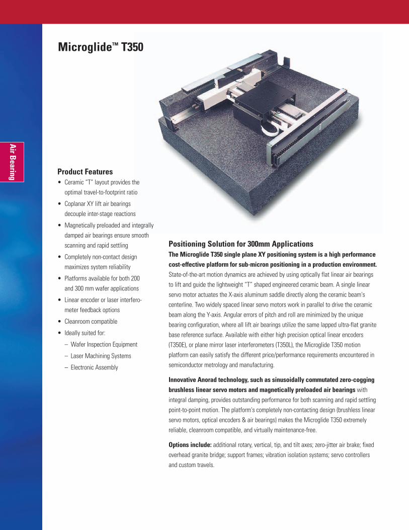
Positioning Solution for 300mm ApplicationsThe Microglide T350 single plane XY positioning system is a high performancecost-effective platform for sub-micron positioning in a production environment.State-of-the-art motion dynamics are achieved by using optically flat linear air bearingsto lift and guide the lightweight “T” shaped engineered ceramic beam. A single linearservo motor actuates the X-axis aluminum saddle directly along the ceramic beam'scenterline. Two widely spaced linear servo motors work in parallel to drive the ceramicbeam along the Y-axis. Angular errors of pitch and roll are minimized by the uniquebearing configuration, where all lift air bearings utilize the same lapped ultra-flat granitebase reference surface. Available with either high precision optical linear encoders(T350E), or plane mirror laser interferometers (T350L), the Microglide T350 motionplatform can easily satisfy the different price/performance requirements encountered insemiconductor metrology and manufacturing.
Innovative Anorad technology, such as sinusoidally commutated zero-coggingbrushless linear servo motors and magnetically preloaded air bearings withintegral damping, provides outstanding performance for both scanning and rapid settlingpoint-to-point motion. The platform's completely non-contacting design (brushless linearservo motors, optical encoders & air bearings) makes the Microglide T350 extremelyreliable, cleanroom compatible, and virtually maintenance-free.
Options include: additional rotary, vertical, tip, and tilt axes; zero-jitter air brake; fixedoverhead granite bridge; support frames; vibration isolation systems; servo controllersand custom travels.
Product Features• Ceramic “T” layout provides the
optimal travel-to-footprint ratio
• Coplanar XY lift air bearings decouple inter-stage reactions
• Magnetically preloaded and integrallydamped air bearings ensure smoothscanning and rapid settling
• Completely non-contact designmaximizes system reliability
• Platforms available for both 200 and 300 mm wafer applications
• Linear encoder or laser interfero-meter feedback options
• Cleanroom compatible
• Ideally suited for:
– Wafer Inspection Equipment
– Laser Machining Systems
– Electronic Assembly
Microglide™ T350
Air Bearing

1104.9
437.3
178.0
178.6
178.6
546.1
1025.5
342.9
330.2203.2
376.2
508.0
178.0
Notes: Specifications are based on overall travel of each axis (significantly better positioning accuracy is possible over shorter travels) and operation in a controlled environment with Anorad approved vibration isolation system. Additional performance, travel, and configuration options are available. Contact Anorad for details.
1 Additional 3 mm overtravel at each end before hard-stops.2 Resolutions available to 0.5 nm (encoder with 8192 x multiplier) or 0.31 nm (laser with λ/2048 interpolation).3 After error mapping axes. 4 Load based on lift bearing capacity. Applied load may determine maximum acceleration.5 Dependent upon system resolution and data rate. 6 Typical dynamics for configured load, acceleration, velocity, resolution and data rate.
SpecificationsPerformance Specifications Units Model T350E Model T350L
Travel 1 mm 350 x 350 350 x 350
Feedback System - Optical LinearEncoder
Plane-MirrorInterferometer
Resolution 2 nm 0.5 - 500 0.31 - 10
Repeatability µm ± 0.15 ± 0.15
Positioning Accuracy 3 µm ± 0.3 ± 0.25
Flatness of Travel µm ± 1.0 ± 1.0
Straightness of Travel µm ± 1.0 ± 0.25
Orthogonality arc-sec ± 2.0 ± 0.5
Pitch, Roll, and Yaw arc-sec ± 1.0 ± 1.0
Maximum Load Capacity 4 kg 50 50
Maximum Velocity 5 mm/s 500 500
Maximum Acceleration 4 m/s2 10 10
Scanning Velocity 5 mm/s 350 350
Average Velocity Ripple 6 % < 1.0 < 1.0
Position Stability 6 counts ± 1 ± 1
25 mm Step-&-Settle Time 6 ms < 200 < 200
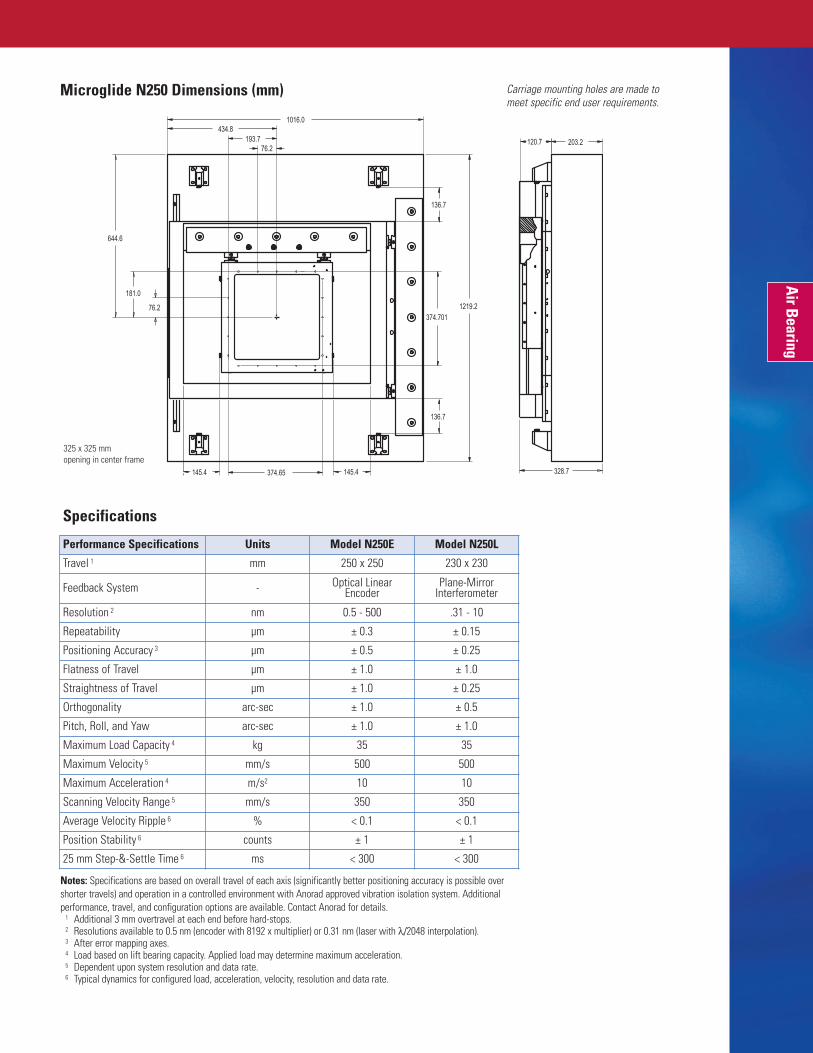
Carriage mounting holes are made to meet specific end user requirements.
Microglide T350 Dimensions (mm)
Air Bearing

Small Open Frame Positioning PlatformThe Microglide N250 features a nested coplanar frame-in-frame dual axisdesign. This configuration allows access to the workpiece from both above and below,to facilitate the use of optics, bottom illumination, vacuum chucks or other applicationspecific subsystems. The X and Y frames are made from precisely machined rigidelectroless nickel plated meehanite iron castings. This produces exceptionally stiff slideswith excellent vibration damping characteristics. The lift air bearings all reference thesame optically flat lapped granite base. This minimizes flatness, pitch, and roll errorstypically found in conventional stacked-stage systems, plus the frame-in-frame designreduces overall system height.
Two side-mounted zero-cogging brushless linear servo motors drive each axisof the Microglide N250. The motors operate in parallel to create a resultant centraldrive force while maintaining an open frame design. This technique eliminates thetwisting torque inherent in single sided drives. Anorad's linear motors are completelynon-contacting to eliminate the backlash, friction, and wear issues normally exhibited by conventional mechanical drives.
The laser feedback option features a frequency stabilized, double pass laserinterferometer with orthogonal plane mirrors. The mirrors are mounted on the inneraxis slide with the laser beams aligned to intersect at the height of the customer part,thus minimizing Abbe offset errors. Linear optical encoder feedback is available using adiffraction grating tape scale.
Options include: additional rotary, vertical, tip, and tilt axes; zero-jitter air brake; fixedoverhead granite bridge; support frames; vibration isolation systems; servo controllersand custom travels.
Product Features• Open frame design for dual-sided
workpiece access and fixturing
• Nested single plane XY air bearingconfiguration provides superiorgeometric accuracy
• Magnetic preload with integraldamping provides smooth scanningand fast settling
• Optional granite bridge assembly for mounting overhead equipment
• Linear incremental encoder or laser interferometer feedback
• Cleanroom compatible
• Ideally suited for:
– Optical Disk Manufacturing
– Microelectronic Test and Inspection Equipment
– X-Ray Lithography
Microglide™ N250
Air Bearing
Shown with optional granite bridge and risers
203.2120.7
328.7
136.7
136.7
1219.2
145.4 145.4
1016.0434.8
193.7
181.0
374.701
374.65
644.6
76.2
76.2
325 x 325 mm opening in center frame
Microglide N250 Dimensions (mm)
Air Bearing
Performance Specifications Units Model N250E Model N250L
Travel 1 mm 250 x 250 230 x 230
Feedback System - Optical LinearEncoder
Plane-MirrorInterferometer
Resolution 2 nm 0.5 - 500 .31 - 10
Repeatability µm ± 0.3 ± 0.15
Positioning Accuracy 3 µm ± 0.5 ± 0.25
Flatness of Travel µm ± 1.0 ± 1.0
Straightness of Travel µm ± 1.0 ± 0.25
Orthogonality arc-sec ± 1.0 ± 0.5
Pitch, Roll, and Yaw arc-sec ± 1.0 ± 1.0
Maximum Load Capacity 4 kg 35 35
Maximum Velocity 5 mm/s 500 500
Maximum Acceleration 4 m/s2 10 10
Scanning Velocity Range 5 mm/s 350 350
Average Velocity Ripple 6 % < 0.1 < 0.1
Position Stability 6 counts ± 1 ± 1
25 mm Step-&-Settle Time 6 ms < 300 < 300
Specifications
Notes: Specifications are based on overall travel of each axis (significantly better positioning accuracy is possible overshorter travels) and operation in a controlled environment with Anorad approved vibration isolation system. Additionalperformance, travel, and configuration options are available. Contact Anorad for details.
1 Additional 3 mm overtravel at each end before hard-stops.2 Resolutions available to 0.5 nm (encoder with 8192 x multiplier) or 0.31 nm (laser with λ/2048 interpolation).3 After error mapping axes. 4 Load based on lift bearing capacity. Applied load may determine maximum acceleration.5 Dependent upon system resolution and data rate. 6 Typical dynamics for configured load, acceleration, velocity, resolution and data rate.
Carriage mounting holes are made tomeet specific end user requirements.

Product Features• Nested XY air bearing system with
common reference plane
• Hybrid ceramic-aluminum framereduces moving mass
• Open frame construction for double-sided workpiece access
• High resolution linear encoder or laser interferometer feedback
• Optional air brake for zero jitterstability at any fixed position
• Optional granite bridge to rigidlymount overhead tooling
• Custom engineering services to meetunique OEM specifications
• Cleanroom compatible
• Ideally suited for:
– Semiconductor Processing
– Flat Panel Manufacturing
– Wafer Scanning
Microglide™ N320
Air Bearing
300mm Wafer Positioning SolutionsAnorad's Microglide N320 nested XY air bearing platforms were created for300mm wafer positioning. Its open frame-in-frame design uses balanced magneticpreload on the lift and guide bearings to maintain extraordinary flatness and straightness.Both axes are actuated by a pair of Anorad zero-cogging linear motors mounted in parallel atopposite sides of each frame. The resultant motive force acts along the centerline of eachaxis, thereby preventing angular pitch and roll errors due to unwanted torque on theindividual axes. Additionally, the outer frame is stabilized horizontally by a pair ofmagnetically preloaded air bearings which glide on a granite reference surface at theplatform's center.
The coplanar nested XY design enables all lift bearings to float atop the sameultra-flat lapped granite reference surface. This minimizes stack up and Abbe errorstypically associated with stacked multi-axis positioning systems, providing maximumaccuracy while giving the system a very compact profile. The N320 also has a highperformance “air brake” for nanometer-level position stability at rest during criticalinspection processes.
The N320 owes its extremely smooth motion to a completely non-contactingsystem design. The magnetically preloaded air bearings and linear optical encodershave virtually no resistance to motion. When actuated by Anorad's sinusoidallycommutated zero-cogging linear motors in conjunction with high resolution feedback, theN320 can move with minimal velocity ripple. Combining this feature with the vibrationdamping characteristics of the air bearings makes this platform ideal for wafer scanningand many other sensitive precision positioning applications.
Options include: additional rotary, vertical, tip, and tilt axes; zero-jitter air brake; fixedoverhead granite bridge; support frames; vibration isolation systems; servo controllers,and custom travels.
Shown with optional granite bridge and risers

165.1165.1
160.3
160.3
228.6
407.0
1397.0
1219.2587.4
749.3
348.7
127.0 Dia Thru hole in
Granite Base Plate Air Bearing
Microglide N320 Dimensions (mm)
Specifications
Carriage mounting holes are made tomeet specific end user requirements.
430 x 430 mm opening incenter frame
Notes: Specifications are based on overall travel of each axis (significantly better positioning accuracy is possible overshorter travels) and operation in a controlled environment with Anorad approved vibration isolation system. Additionalperformance, travel, and configuration options are available. Contact Anorad for details.
1 Additional 3 mm overtravel at each end before hard-stops.2 Resolutions available to 0.5 nm (encoder with 8192 x multiplier) or 0.31 nm (laser with λ/2048 interpolation).3 After error mapping axes. 4 Load based on lift bearing capacity. Applied load may determine maximum acceleration.5 Dependent upon system resolution and data rate. 6 Typical dynamics for configured load, acceleration, velocity, resolution and data rate.
Performance Parameters Units Model N320E Model N320L
Travel 1 mm 320 x 320 320 x 320
Feedback System - Optical LinearEncoder
Plane-MirrorInterferometer
Resolution 2 nm 0.5 - 500 0.31 - 10
Repeatability µm ± 0.3 ± 0.15
Positioning Accuracy 3 µm ± 0.5 ± 0.2
Flatness of Travel µm ± 1.0 ± 1.0
Straightness of Travel µm ± 1.0 ± 0.25
Orthogonality arc-sec ± 2.0 ± 0.5
Pitch, Roll, and Yaw arc-sec ± 1.0 ± 1.0
Maximum Load Capacity 4 kg 35 35
Maximum Velocity 5 mm/s 500 500
Maximum Acceleration 4 m/s2 10 10
Scanning Velocity 5 mm/s 350 350
Average Velocity Ripple 6 % < 1.0 < 1.0
Position Stability 6 counts ± 1 ± 1
25 mm Step-&-Settle Time 6 ms < 400 < 400

Precision Solution for Flat Panel ApplicationsThe Microglide FP720 is a single plane XY hybrid air-mechanical bearingsystem that provides a cost-effective solution for high precision positioning of flat panel displays. Extremely smooth motion dynamics are achieved by utilizingoptically flat linear air bearings and a “T-shaped” engineered-ceramic beam with anoptimized stiffness to weight ratio. A single linear servo motor actuates the preloaded air bearing X-axis aluminum saddle directly along the ceramic beam's centerline. Twowidely spaced linear servo motors work in parallel to guide the ceramic beam in the Y-axis direction. Angular errors of pitch & roll are minimized by the unique air-bearingconfiguration, where the X-axis lift and the ceramic beam's outer-support air bearingsutilize the same lapped ultra-flat granite base reference surface. High-precision opticallinear encoders are available in a broad range of resolutions to satisfy the differentaccuracy and speed requirements typically encountered in flat panel metrology and manufacturing.
Innovative Anorad engineering combines sinusoidally commutated zero-cogging brushless linear servo motors and magnetically preloaded air bearingswith integral damping to deliver excellent performance in both scanning and rapidsettling point-to-point motion. The primarily non-contact nature of the system makes the FP720 and FP1020 platforms extremely reliable and essentially maintenance-free.
Options include: additional rotary, vertical, tip, and tilt axes; zero-jitter air brake; fixedoverhead granite bridge; support frames; vibration isolation systems; servo controllersand custom travels.
Product Features• Single plane XY air bearing
configuration provides superiorgeometric accuracy
• Magnetic preload with integraldamping provides smooth scanningand fast settling
• Hybrid bearing system offers excellentvalue and performance
• Overhead beam option for mountingprocess equipment
• Travel to 1020 mm
• Velocities to 300 mm/s
• Linear encoder feedback
• Cleanroom compatible
• Ideally suited for:
– Flat Panel Equipment
– Laser Machining Systems
– Electronic Assembly
Microglide™ FP720
Air Bearing
Shown with optional granite bridge and risers

375.7
203.2
1447.8[1500]
364.0[388]
364.0[388]
689.8[714]
880.1[1031.6]
1727.2[2030]
364.0 [514.0]
364.0[514.0]
431.8
439.4
219.7
Microglide FP720 Dimensions (mm) [FP1020 Dimensions]
Specifications
Carriage mounting holes are made tomeet specific end user requirements.
Performance Parameters Units Model FP720E Model FP1020E7
Travel 1 mm 720 x 720 1020 x 765
Feedback System - Optical LinearEncoder
Optical LinearEncoder
Resolution 2 nm 0.5 - 500 0.5 - 500
Repeatability µm ± 0.4 ± 0.5
Positioning Accuracy 3 µm ± 0.5 ± 1.0
Flatness of Travel µm ± 3.0 ± 3.0
Straightness of Travel µm ± 3.0 ± 3.0
Orthogonality arc-sec ± 1.0 ± 1.0
Pitch, Roll, and Yaw arc-sec ± 2.0 ± 3.0
Maximum Load Capacity 4 kg 80 80
Maximum Velocity 4 mm/s 500 500
Maximum Acceleration 4 m/s 2 10 10
Scanning Velocity Range 5 mm/s 350 350
Average Velocity Ripple 6 % < 1.5 < 1.5
Position Stability 6 counts ± 2 ± 2
25 mm Step-&-Settle Time 6 ms < 450 < 450
Notes: Specifications are based on overall travel of each axis (significantly better positioning accuracy is possible over shorter travels) and operation in a controlled environment with Anorad approved vibration isolation system.Additional performance, travel, and configuration options are available. Contact Anorad for details.
1 Additional 3 mm overtravel at each end before hard-stops.2 Resolution available to 0.5nm (8192x encoder multiplier) .3 After error mapping axes. 4 Load based on lift bearing capacity. Applied load may determine maximum acceleration.5 Dependent upon system resolution and data rate.6 Typical dynamics for configured load, acceleration, velocity, resolution and data rate.7 FP1020 dimensions [in square parenthesis].
Air Bearing
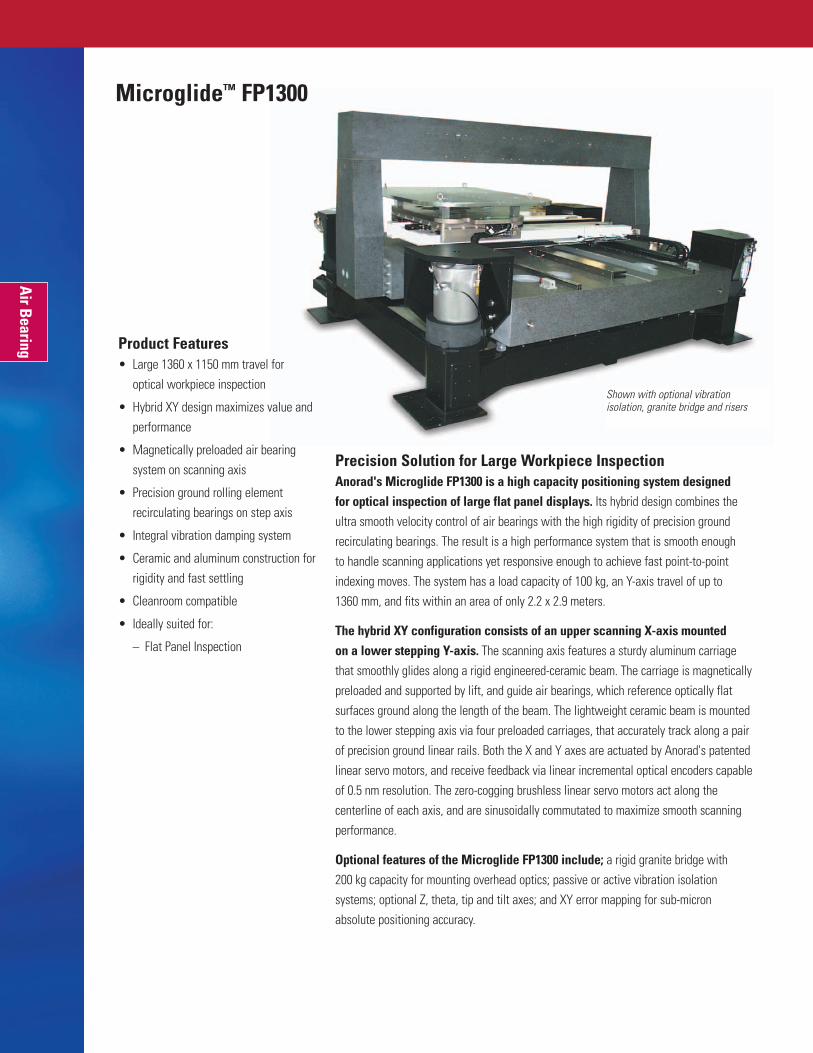
Precision Solution for Large Workpiece InspectionAnorad's Microglide FP1300 is a high capacity positioning system designed for optical inspection of large flat panel displays. Its hybrid design combines theultra smooth velocity control of air bearings with the high rigidity of precision groundrecirculating bearings. The result is a high performance system that is smooth enough to handle scanning applications yet responsive enough to achieve fast point-to-pointindexing moves. The system has a load capacity of 100 kg, an Y-axis travel of up to 1360 mm, and fits within an area of only 2.2 x 2.9 meters.
The hybrid XY configuration consists of an upper scanning X-axis mounted on a lower stepping Y-axis. The scanning axis features a sturdy aluminum carriagethat smoothly glides along a rigid engineered-ceramic beam. The carriage is magneticallypreloaded and supported by lift, and guide air bearings, which reference optically flatsurfaces ground along the length of the beam. The lightweight ceramic beam is mountedto the lower stepping axis via four preloaded carriages, that accurately track along a pairof precision ground linear rails. Both the X and Y axes are actuated by Anorad's patentedlinear servo motors, and receive feedback via linear incremental optical encoders capableof 0.5 nm resolution. The zero-cogging brushless linear servo motors act along thecenterline of each axis, and are sinusoidally commutated to maximize smooth scanningperformance.
Optional features of the Microglide FP1300 include; a rigid granite bridge with 200 kg capacity for mounting overhead optics; passive or active vibration isolationsystems; optional Z, theta, tip and tilt axes; and XY error mapping for sub-micronabsolute positioning accuracy.
Product Features• Large 1360 x 1150 mm travel for
optical workpiece inspection
• Hybrid XY design maximizes value andperformance
• Magnetically preloaded air bearingsystem on scanning axis
• Precision ground rolling elementrecirculating bearings on step axis
• Integral vibration damping system
• Ceramic and aluminum construction forrigidity and fast settling
• Cleanroom compatible
• Ideally suited for:
– Flat Panel Inspection
Microglide™ FP1300
Air Bearing
Shown with optional vibration isolation, granite bridge and risers

2870.0
2200.0
729.0
1005.0684.0 684.0
1097.6
1433.6
579.0
579.0
Carriage mounting holes are made tomeet specific end user requirements.
Air Bearing
Microglide FP1300 Dimensions (mm)
Specifications
Performance Specifications Units Model FP1300
Travel 1 (X-Y) mm 1150 x 1360
Feedback System – Optical LinearEncoder
Resolution 2 nm 0.5 - 500
Repeatability µm ± 0.5 X± 1.0 Y
Positioning Accuracy 3 µm ± 1.5 X± 2.5 Y
Flatness of Travel µm ± 3.0 X± 6.0 Y
Straightness of Travel µm ± 3.0 X± 4.0 Y
Orthogonality arc-sec ± 3.0Pitch, Roll, and Yaw arc-sec ± 5.0, ± 5.0, ± 2.5Maximum Load Capacity 4 kg 100Maximum Velocity 5 mm/s 500Maximum Acceleration 4 m/s 2 10Scanning Velocity 5 mm/s 350Average Velocity Ripple 6 % 1.0Position Stability 6 counts ± 2
Notes: Specifications are based on overall travel of each axis (significantly better positioningaccuracy is possible over shorter travels) and operation in a controlled environment with Anoradapproved vibration isolation system. Additional performance, travel, and configuration options areavailable. Contact Anorad for details.
1 Additional 3 mm overtravel at each end before hard-stops.2 Resolutions available to 0.5 nm (8192 x encoder multiplier).3 After error mapping axes. 4 Load based on lift bearing capacity. Applied load may determine maximum acceleration.5 Dependent upon system resolution and data rate. 6 Typical dynamics for configured load, acceleration, velocity, resolution and data rate.

Fast-Turn Gate Array Prototyping • Coplanar XY air bearing system
• Compact design with 50 mm x 50 mm travel
• Rigid ceramic beams with lapped granite base
• Interferometric encoders with 2 nanometer resolution
• Zero-cogging linear motors
• Class 10 cleanroom compatible
Hi-Resolution Computer-to-Plate (CTP) Stage• 1000 mm travel single axis stage
• 0.01% constant velocity control
• Magnetically preloaded air bearings
• Sinusoidally commutated zero-cogging linear motor
• Completely non-contacting design
Bumped Wafer Inspection System• Cost effective hybrid bearing design
• Air bearing scan axis and mechanical bearing step axis
• Engineered ceramic matrix composite beam for maximum stiffness
• SEMI S2, S8, and CE compliant
• Class 100 cleanroom compatible
Engineered-to-Order Systems
Air Bearing

Wafer Inspection XY Stage• Modular stacked air bearing stage assembly
• Integral wafer chuck
• Internal cable management
Wafer Stepper Lithography System• Dual, parallel, nested coplanar
XY air bearing stages
• Plane mirror laser interferometer feedback
• Active damping minimizes vibrations
• Dynamic environmental isolation
Six-Axis Wafer Stepper• High accuracy nested coplanar XY platform
• Integral Z, theta, tip, and tilt axes
• Custom vacuum chuck for automated wafer handling
• Plane mirror laser interefometer feedback
Air Bearing
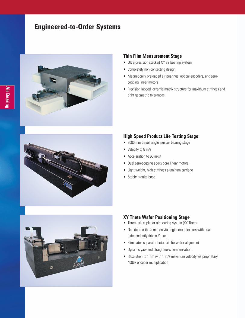
Thin Film Measurement Stage• Ultra-precision stacked XY air bearing system
• Completely non-contacting design
• Magnetically preloaded air bearings, optical encoders, and zero-cogging linear motors
• Precision lapped, ceramic matrix structure for maximum stiffness andtight geometric tolerances
High Speed Product Life Testing Stage• 2000 mm travel single axis air bearing stage
• Velocity to 8 m/s
• Acceleration to 60 m/s2
• Dual zero-cogging epoxy core linear motors
• Light weight, high stiffness aluminum carriage
• Stable granite base
XY Theta Wafer Positioning Stage• Three axis coplanar air bearing system (XY Theta)
• One degree theta motion via engineered flexures with dualindependently driven Y axes
• Eliminates separate theta axis for wafer alignment
• Dynamic yaw and straightness compensation
• Resolution to 1 nm with 1 m/s maximum velocity via proprietary 4096x encoder multiplication
Engineered-to-Order Systems
Air Bearing

Contact Information for Anorad Products
Main LocationsU.S.A.Rockwell Automation100 Precision DriveShirley, NY 11967-4710Tel: 631.344.6600Toll Free: 1.888.77ANORADFax: 631.344.6601Email: [email protected]: www.anorad.com
EuropeRockwell AutomationDe Dintel 8-125684 PS BestThe NetherlandsTel: +31.499.338585Fax: +31.499.338580Email: [email protected]
Global Sales OfficesUnited KingdomRockwell AutomationViewpoint Basing ViewBasingstoke, HampshireRG21 4RG EnglandTel: +44.0.1256.799827Fax: +44.0.1256.799829Email: [email protected]
JapanRockwell Automation6-5, Nishiki, 1-chomeNaka-ku, Nagoya 460-0003JapanTel: +81.52.222.7060Fax: +81.52.222.7065Email: [email protected]
KoreaRockwell Automation3F Gusang Bd.1009-5 Daechi-dongKangnam-guSeoul Korea 135-280Tel: +82.2.2188.4400Fax: +82.2.564.8760Email: [email protected]
TaiwanRockwell Automation 7F, No. 19, Sec. 1Hang Zhou S. RoadTaipei 100, TaiwanTel: +886.2.2358.1883Fax: +886.2.2351.9400Email: [email protected]
AustraliaRockwell Automation 37 Chapman StreetBlackburn, Victoria 3130AustraliaTel: +61.3.9896.0300Fax: +61.3.9890.0953Email: [email protected]
ItalyRockwell Automation Via Rondo’ Bernardo, 5Stupinigi (TO)Italy 10040Tel: +39.011.398.2200Fax: +39.011.398.2208Email: [email protected]
ChinaRockwell Automation 4/F, Office Tower 1Henderson Center18 Jianguomennei Ave.Dong Chen DistrictBeijing, China 100005Tel: +86.10.6518.2535Fax: +86.10.6518.2536Email: [email protected]