microscience manual - camdu
TRANSCRIPT

0
Microscience Manual
Physics Students’ Manual
Second Guyana Version Adaptation of Teaching and Learning
Materials on Microscience Experiments
Funded by UNESCO in collaboration with the Ministry of Education and the University of
Guyana
Updated on: April 10, 2015

1
Contents
Participants ................................................................................................................................................... 2
A Message from the Minister of Education ................................................................................................. 3
Introduction to the first Guyana version adaptation of UNESCO teaching and learning materials on micro science experiments ..................................................................................................................................... 4
EXPERIMENT 1 – GET TO KNOW YOUR MICRO-ELECTRICITY KIT .................................................................. 5
EXPERIMENT 2 – LIGHTEN UP, PREDICT AND EXPLORE ................................................................................ 7
EXPERIMENT 3 –CAR HEADLIGHTS ............................................................................................................... 9
EXPERIMENT 4 – MAKING AN ELECTRIC CURRENT DETECTOR ................................................................... 11
EXPERIMENT 5 – THE CURRENT IN A SERIES CIRCUIT ................................................................................. 13
EXPERIMENT 6 – LIGHT BULBS IN SERIES .................................................................................................... 15
EXPERIMENT 7 – LIGHT BULBS IN PARALLEL ............................................................................................... 17
EXPERIMENT 8 – ONE AFTER THE OTHER, CAUSING A GREAT BOTHER ..................................................... 19
EXPERIMENT 9 – FREE ELECTRONS ARE NOT SO FREE! .............................................................................. 21
EXPERIMENT 10 – WHAT GOES UP MUST FALL DOWN .............................................................................. 27
EXPERIMENT 11 – THE CURRENT IN A SERIES CIRCUIT ............................................................................... 29
EXPERIMENT 12 – THE REAL & THE IDEAL WORLD .................................................................................... 31
EXPERIMENT 13 – THE INVESTIGATION ..................................................................................................... 33
EXPERIMENT 14 – POTENTIAL DIFFERENCE ACROSS POINTS IN A SERIES CIRCUIT .................................... 34
EXPERIMENT 15 – POTENTIAL DIFFERENCE ACROSS POINTS IN A PARALLEL CIRCUIT ............................... 35
EXPERIMENT 16 – OHM’S LAW ................................................................................................................... 37
EXPERIMENT 17 – SOLENOIDS & ELECTROMAGNETS ................................................................................ 39
EXPERIMENT 18 – FEDERAL BUREAU of INVESTIGATIONS, FBI .................................................................. 41
EXPERIMENT 19 – COMING ATTRACTION ................................................................................................... 44
EXPERIMENT 20 – FIELDING ........................................................................................................................ 46
EXPERIMENT 21 – THE STRONGEST OF THEM ALL! .................................................................................... 49
EXPERIMENT 22 – AMMETER, TO BE AND NOT TO BE ............................................................................... 51
EXPERIMENT 23 – ELECTRIC MOTOR 1 ....................................................................................................... 53
EXPERIMENT 24 – ELECTRIC MOTOR 2 ....................................................................................................... 55
EXPERIMENT 25 – CAN MAGNETISM PRODUCE ELECTRICITY? .................................................................. 57
EXPERIMENT 26 – ON, OFF-OFF, ON ........................................................................................................... 59
EXPERIMENT 27 – WHAT IS ELECTRICAL POTENTIAL DIFFERENCE? ........................................................... 61

2
EXPERIMENT 28 – THE MAXIMUM POTENTIAL ENERGY OUTPUT OF A BATTERY ...................................... 63
The Ministry of Education wishes to acknowledge the work of the consultations on selecting the Microscience Experiments for Biology, Chemistry and Physics which are relevant to the national curriculum.
Participants
Name Institution Mr. Gregory Blyden Faculty of Natural Sciences - University of Guyana Mr. Mohandatt Goolsarran Ministry of Education - NCERD Mr. Navindra Hardyal Queens College Mr. Sirpaul Jaikishun Faculty of Natural Sciences - University of Guyana Ms. Petal Jetoo Ministry of Education - NCERD Ms. Noella Joseph Cyril Potter College of Education Ms. Samantha Joseph Faculty of Natural Sciences - University of Guyana Mr. Azad Khan School of Education and Humanities - University of Guyana Mr. Patrick Ketwaru Faculty of Natural Sciences - University of Guyana Professor Lloyd Kunar Physics Department - University of Guyana Mr. Marvin Lee Queens College Mr. Andrew Mancey School of the Nations Mr. Gary Mendonca Faculty of Natural Sciences – University of Guyana M. Kamini Ramrattan Richard Ishmael Secondary School Ms. Wendel Roberts Ministry of Education – NCERD Ms. Medeba Uzzi Faculty of Natural Sciences – University of Guyana

3
A Message from the Minister of Education
‘The steady decline of enrolment of young people in science is cause for concern, and it is in this endeavour that UNESCO’s work in Science Education aims to make a difference. In a world that is increasingly shaped by science and technology, the team recognizes this and has made it its mission to not only spread education but to make an interest in the Sciences a prominent and lasting feature wherever it is offered’.(UNESCO, 2011). One approach used by UNESCO is its Global Micro-science Experiments Project which provides developed and developing countries alike with new teaching tools. This Global Micro-science Experiments Project is a hands-on science education project that gives primary and secondary school students as well as university students the opportunity to conduct practical work in physics, chemistry and biology, using kits that come with booklets. The project thus contributes to capacity building, in areas where limited/no laboratory facilities are available. The experimental techniques that can be covered on a micro-scale include everything from separating the components of mixtures to measuring rates of reactions between chemicals.
The Ministry of Education, Guyana collaborated with UNESCO to initiate the Global Micro-science Experiments project as a pilot for fifteen secondary schools in 2012. Ninety-five percent (95%) of secondary schools are now equipped with the micro-science kits and supporting manuals. This project was embraced to support the Ministry’s drive to improve enrolment in the single sciences. A twenty percent (20 %) increase in student enrolment was recorded since the introduction of this programme. We remain committed to transforming Guyana through Science and Technology in Education.
Guyana now leads UNESCO’s Global Microscience Experiments Project in the Caribbean and is willing to partner CXC territories in providing assistance.
It is my sincere hope that this manual will be used to encourage interactive learning which fosters the development of critical thinking skills by students.
Hon. Dr. Priya D. Manickchand Minister of Education Guyana April 2015

4
Introduction to the first Guyana version adaptation of UNESCO teaching and learning
materials on micro science experiments
The contents of this document are recommended by the participants of
UNESCO/Kingston/Ministry of Education, NCERD consultations on Micro-Science Experiments
held in Georgetown (Guyana) on 27-30 June, 2011. The present materials correspond fully to
the existing National Curriculum for teaching basic sciences at the different levels. The
materials were selected by the participants of the working consultations. The participants
worked with teaching and learning packages on microscience experiments which are available
on UNESCO’s website and are free for all types of adaptations and modifications. The different
types of microscience kits donated by UNESCO/Kingston Office to Guyana can be used in
practical classes. The experiments are classified according to grades and some were given first
priority (refer to appendix 1). The ‘priority one’ experiments are recommended for the pilot of
the microscience experiments. It is very clear that, new experiments can be developed and
tested using the same kit, as proposed by the participants of the working consultations which
included curriculum development specialists. Developing new materials can be recommended,
as a second stage of the project development. It is noted that the microscience experiments, as
a new methodology for hands on laboratory work by students, can work in conjunction with
macroscience experiments. Furthermore the microscience kits can be used by teachers for
demonstration purposes. We hope, that the Science Teachers in Guyana will find the
microscience experiments methodology and teaching and learning materials, interesting and of
great value for the enhancement of science education.
Participants of the working consultations
May 2012

5
EXPERIMENT 1 – GET TO KNOW YOUR MICRO-ELECTRICITY KIT
CSEC OBJECTIVE (S): Section D – Objectives 4.1-4.4
Grade Level - 9
Nowadays everything is going “micro”, which of course means “small”. This micro fever, ranges from computers and Hi-Tech equipment to laboratory equipment. Micro-things become more and more affordable, they are easy to carry and easy to store. In schools all over the world, micro-equipment invades the classrooms and changes the way of teaching and learning. Work with your micro-electricity kit and you will find out why. What you need
micro-electricity kit, an A4 sheet of white paper WHY DO WE USE ELECTRIC CIRCUITS?
1 We use electric circuits to transfer electrical energy to various electrical devices. These devices transform the electrical energy into other forms of energy, which we find useful! a) Make a list of five devices which you can find at home, or you see in the shops, which work
with electricity. b) What are these devices used for? c) What energy transformation/s take place in these devices?
WHAT IS AN ELECTRIC CIRCUIT?
2 An electric circuit is a closed path or “loop”, made out of materials which are good conductors of electricity. But this is not enough!
a) Phoka is a learner in your group. He takes a piece of wire. He connects the ends of the wire together. He says: “This is an electric circuit!”. Is Phoka right? Is there an electric current in Phoka’s wire loop?
b) What must Phoka do to have an electric current in his loop? Explain to him.
c) Phoka connects a 1,5 V cell across his wire. Did he make an electric circuit?
d) Andile, who is also a learner in your group, has her doubts about Phoka’s circuit. She says: “This is the most useless circuit I have ever seen! It is of no use!” Is Andile right? Is Phoka’s circuit a “useless“ circuit? Explain.
e) e So finally, what is an electric circuit and what parts does it need to be made of to make it “useful”?
What to do: Work steps 1 to 4 below, individually. 1. Put the A4 sheet of paper flat on your desk in front of you. Put your micro-electricity kit on the
A4 paper. 2. Empty the contents of the kit on the white paper, one by one. 3. Look at the diagram of all the components in the kit. Find the name of each component in the

6
diagram. 4. Divide your components into four parts/categories,
I. i the power sources and any other accessories which you think go with them. II. ii the electrical devices, which you think “will do something” when you connect them in
a circuit. III. iii components which you think you can use for the connections, i.e. which you can use
to connect a power source to an electrical device to complete a closed conducting path. IV. iv components which do not belong in any of the above three categories. Think of ways
you can use these components with your kit. 5. Look at how the other members of your group have divided their components. Discuss any
differences. Here are some ideas of how to use some of the components in the kit. But of course, you may have better ones. You must try your ideas!
TASK 1 - MAKE YOUR OWN CIRCUIT
6. The following diagram, shows a simple electric circuit - for inspiration! Your task is to make a bulb glow, using components from your micro-electricity kit. Each learner in your group must make a different circuit. And each circuit must be different from the one shown in the diagram. When you have finished, discuss the circuits you and your group have made. Discuss which connections or components you found the easiest to use. Discuss which type of connection/s you found more firm or sturdy.

7
EXPERIMENT 2 – LIGHTEN UP, PREDICT AND EXPLORE
CSEC OBJECTIVE (S): Section D – Objectives 4.1-4.4
Grade Level - 9
TASK 2 - FIND OUT HOW IT WORKS
7. In your micro-electricity kit, you will find a little red bulb, the LED. This is a diode. Diode is a Greek word for “Two-Way”. Your task is to find out how it works. How can you make it glow? Why is it called “Two-Way”?
What is electricity? What is an electric current? These are not easy questions, yet electricity is so much part of our lives. The more we learn about it, the more we learn to respect nature and the energy it provides us! In the past you made simple circuits and you learned how to light up a bulb. This Activity is nothing new, but hopefully it will challenge you to think, and refresh your memory ..... not bad for starters! What you need
a micro-electricity kit PART A
1. The diagram alongside, shows what a bulb looks like inside. 2. Predict which of the bulbs in the following figures will light
up. Work on your own.
a) Record your predictions in the table on the next page.
b) Compare your predictions with those of other members of your group. Where you differ explain

8
the reason for your prediction. Make a group prediction and record it in the table on the next page.
PART B
3. Test your group predictions using the micro-electricity kit equipment. a) Record your observations in the table on the next page. b) Compare your observations with your predictions. Explain the results you observe. Add your
comments in the table on the next page. 4. To conclude, what is necessary to make a bulb light up?
TABLE
Bulb Your Prediction Group’s Prediction
Observation Comments
A
B
C
D
E
F
G
H
I
J
K
L
M
N1
N2

9
EXPERIMENT 3 –CAR HEADLIGHTS
CSEC OBJECTIVE (S): Section D – Objectives 4.1-4.4
Grade Level - 9
To use the electrical energy in cells or batteries to make light bulbs glow we need a closed circuit. There are two common types of circuits, the series circuits and the parallel circuits. In a series circuit, all the parts of the circuit are connected, one after the other, so there is only one path for the transfer of electrical energy. In a parallel circuit, the parts are connected so that there is more than one path. Organise yourselves in pairs or groups of three. Select one person to take notes. Discuss the following factors about the main headlights of a car (or taxi):
x during which part of the day are the headlights of a car used? x the importance of passenger safety when designing car headlights x what would happen if one of the car headlights was broken for example, by a stone thrown
up from another car? x the electric circuit in a car which connects the car battery to the two headlights.
After you have noted down your answers to the above points, draw a diagram representing an electric circuit which consists of the two headlights of a car, the car battery (source of electrical energy) and the wires that connect the headlights to the car battery. What you need
a micro-electricity kit What to do
Select parts of the micro-electricity kit and set up a circuit to represent your circuit drawing of the headlights of a car. When you have finished the above Activity get together with your group and work through this section.
1. Which circuit, series or parallel, describes the circuit you have constructed? Explain.
2. You can spend a lot of time drawing the real parts (components) of a circuit. It is much easier to use symbols to represent the components of a circuit.
On the next page there are some of the symbols used to draw circuit diagrams.

10

11
EXPERIMENT 4 – MAKING AN ELECTRIC CURRENT DETECTOR
CSEC OBJECTIVE (S):
Grade Level - 9
In Grade 7 you met the concept of electrical energy and some of its many uses. Think of a torch for example. Energy stored in the cells of the torch, transfers to the bulb and the bulb glows. To transfer electrical energy we need an electrical circuit. An electrical current transfers energy in a circuit. There are some substances which allow an electric current in them(conductors) and other substances which do not allow an electric current (insulators). What you need
a micro-electricity kit What to do
Work in pairs. Use different parts of the micro-electricity kit to construct a device that can detect the presence of an electric current. The following criteria (things you need to do) must be considered when designing your detector.
x the device must be easy to use x the device must show whether a current is present or not.
When you have constructed your device, test it on as many objects around you as possible. Before you test an object, predict whether it is a conductor or insulator. Enter your results in the table below.
TABLE
Tested object Current Prediction Y yes ¥no
Confirmed Prediction Y right ¥ wrong
Explanation
eg. a nail Y Y metals conduct

12
What to discuss
1. Describe each part of your current detector and how it contributes to the working of the detector.
2. The objects that you tested today were all solids. Discuss whether some gases and liquids can conduct electricity? If they do, could your detector be used to test these substances? Explain.
3. How do conductors and insulators make our day to day living easier and safer? Give at least four examples.

13
EXPERIMENT 5 – THE CURRENT IN A SERIES CIRCUIT
CSEC OBJECTIVE: Section D – Objectives 4.1-4.4
Grade Level - 9
In a series circuit there is only one closed path for the current. The strength of the current is the same anywhere in the circuit. What you need
a micro-electricity kit What to do
Work in pairs or groups of three. Use the micro-electricity kit to construct the series circuits given in the figures below. Complete the given table. Remember to predict the brightness of the bulb before you close the switch.
Bulb’s position Brightness Prediction Bulb brightness
Before switch
After switch
Before battery

14
What to discuss
1. Thando is a Grade 8 learner. When he was asked by his teacher to describe the current in a series circuit he said the following: “The strength of the current before the light bulb is bigger. This is because the current goes through the light bulb and gets used up.” Discuss Thando’s statement.
2. In your micro-electricity kit is a part called a resistor. A resistor is a specially designed device to reduce the current in a circuit. Some parts of a circuit cannot work properly if they have large currents in them. If you ever get the chance, look inside a radio or TV. You will see many, many resistors. Predict the brightness of the light bulb in your series circuit if you were to replace one of the copper strips with a resistor. Set up such a circuit and test your prediction. (You may need to add an LED to your series circuit.) How accurate was your prediction? Discuss.
15
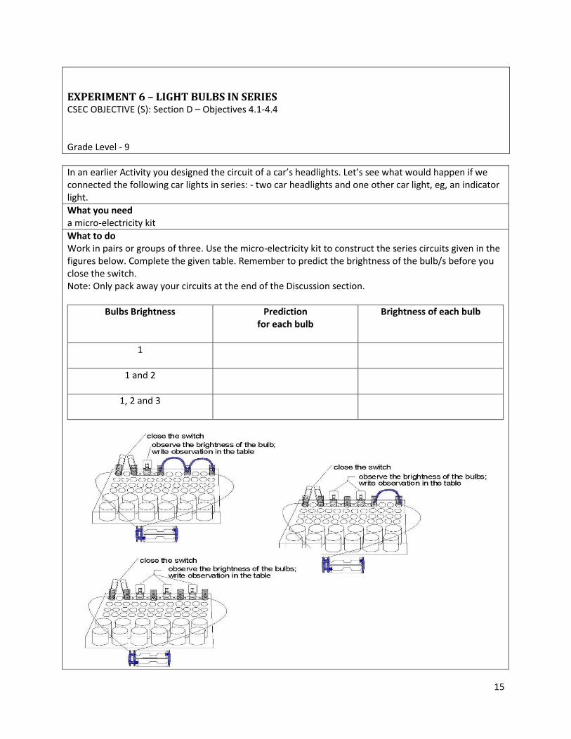
EXPERIMENT 6 – LIGHT BULBS IN SERIES
CSEC OBJECTIVE (S): Section D – Objectives 4.1-4.4
Grade Level - 9
In an earlier Activity you designed the circuit of a car’s headlights. Let’s see what would happen if we connected the following car lights in series: - two car headlights and one other car light, eg, an indicator light. What you need
a micro-electricity kit What to do
Work in pairs or groups of three. Use the micro-electricity kit to construct the series circuits given in the figures below. Complete the given table. Remember to predict the brightness of the bulb/s before you close the switch. Note: Only pack away your circuits at the end of the Discussion section.
Bulbs Brightness Prediction
for each bulb
Brightness of each bulb
1
1 and 2
1, 2 and 3
16
What to discuss
1. Describe the changes of the brightness of the bulbs, in terms of electrical current, each time another bulb is added in series.
2. In an earlier Activity you met an electrical device called a resistor. a) What similarities are there between the extra light bulbs added in series and the resistor.
We call the property of a substance that reduces current strength, resistance. b) Each light bulb has a certain resistance. Discuss, in terms of resistance, how the addition of
each light bulb affects the current in a series circuit. 3. Predict what will happen if you unscrewed the first light bulb in the last series circuit you set up.
Test your prediction. Explain the result. 4. Let’s consider the possibility of connecting two car headlights and an indicator light in series.
What disadvantages and advantages would there be?

17
EXPERIMENT 7 – LIGHT BULBS IN PARALLEL
CSEC OBJECTIVE (S): Section D – Objectives 4.1-4.4
Grade Level - 9
In an earlier Activity you met the circuit of car headlights. Car headlights are connected in parallel. Let’s look at the advantages of connecting the headlights in parallel. What you need
a micro-electricity kit What to do
Work in pairs or groups of three. 1. Use the micro-electricity kit to construct
the parallel circuit as shown on the right. 2. Predict whether the other bulbs will glow
if you unscrew one bulb. 3. Test your prediction. 4. Predict whether the other bulbs will glow
if you unscrew two bulbs. 5. Test your prediction. 6. Complete the given table.
Bulbs ‘Glow’ Prediction for each bulb ‘Glow’ of each bulb
Remove 1 bulb
Remove 2 bulbs
What to discuss
1. How do light bulbs connected in parallel differ to light bulbs connected in series? 2. You are given some examples of some common circuits below:
Christmas tree lights, traffic lights (robots), torch, ceiling lights in the home, street lights; a) Which circuits are parallel and which are series? b) Give the reasons for your choices.
3. COMPLETE THIS QUESTION ON YOUR OWN. After everyone has finished the questions compare answers. If you disagree set up the circuits to check. You are given some circuit diagrams. Chose the correct multiple choice answer for each. a) If the light bulb M suddenly “burns out”, what happens to light
bulb N? A. It glows exactly as before B. It glows brighter C. It glows less bright D. It does not glow
b) Which bulb/s will glow with the same intensity (same
brightness)?
18
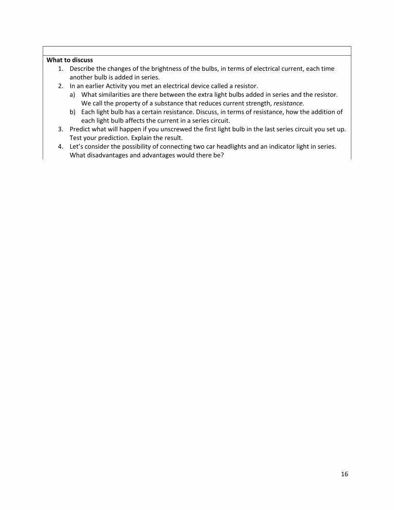
All the bulbs are identical. A. 1 and 2 B. 2 and 3 C. 1, 2 and 3 D. 3 and 4
a) Which bulb must be removed from the circuit to make ALL the other bulbs go out? A. 1 B. 2 C. 3 D. 4
b) Lebala, a Grade 8 learner connects three light bulbs called P, Q and R to two cells. Which circuit diagram corresponds exactly to the circuit she set up.

19
EXPERIMENT 8 – ONE AFTER THE OTHER, CAUSING A GREAT BOTHER
CSEC OBJECTIVE (S): Section D – Objectives 4.12 Grade Level - 9
TABLE 1
Resistors connected in circuit
Current, I (mA)
Voltage across each resistor, Vx
(volts)
Voltage across all resistors,
V (Volts)
V1 V2 V3 V4 1
1+2
1+2+3
1+2+3+4
3. On the graph paper, plot the potential difference across the first resistor (V1), versus the current (I) in the circuit. Then, draw a smooth (best fit) line.

20
What to discuss
In the following steps, you will discuss the sort of information you can get from: i. Table 1, and
ii. the graph of V1 vs I 4. Lebala, is a learner in your group. She has just drawn a nice, clear graph of V1 vs I.
Lebala says: “Here is my graph, but so what? Why waste time drawing graphs?” The learners in your group must explain to Lebala the role of a graph. What information can she get from her graph of V1 vs I? How can she use her graph? Examples of some points you can include in your discussion are:
x What does the graph represent? x What type of relationship does the graph show? x Is it necessary to include the origin? Explain. x How can the graph be useful? Give examples.
5. What information can you get from Table 1? Make a list of all information which you consider important.
6. Lebala looks at Table 1. “We can get more information from Table 1, which I cannot see on the graph. See what the text-book says:
POINT 1: The total voltage supplied by the source, is equal to the sum of the voltages across each resistor, i.e. V1 + V2 + V3 + ....... = V. POINT 2: The ratio Vx/I remains constant where, Vx is the voltage across a single resistor and I is the current in the circuit. Lebala says, “There was no need to draw a graph after all!”
a) Use your data in Table 1, to see if Points 1 and 2 in Lebala’s text-book are verified by your experiment. Record your calculations in a table. Discuss your results with your group.
b) Lebala thinks that in this Activity, there is no need to draw a graph. What do you think? Explain. 7. The ratio of V1/I in Table 1, represents a constant quantity called the resistance, (R),
of the resistor. Every electrical conductor, like the resistors you used in this Activity, has a resistance R. Discuss in your group and write down a few sentences on what you understand by the term “resistance”. What does the ratio V/I mean?