microscope
TRANSCRIPT

THE COMPOUND LIGHT MICROSCOPE
The microscope is invented by Zacharias Janssen.
The compound microscope is called so because, in contrast to a single magnifying convex lens, it has two such lenses: the objective and the eyepiece. (1) Base, (2) Pillars, (3)Handle, (4) Body tube, (5) Coarse adjustment screw, (6) Fine adjustment screw, (7) Fixed stage, (8) Mechanical stage, (9)Fixed and revolving nose pieces, (10) Objective lenses, (11)Mirror, (12) Condenser, (13) Eye-piece, and (14) iris
PARTS OF MICROSCOPE
1) The support (framework) system
2) The illumination system
3) The magnification system
4) The adjustment or focusing system
THE SUPPORT SYSTEM
1) BASE: supports the microscope on the worktable to provide maximum stability.
2) PILLARS: two upright pillars project upwards from the base, and the handle of the microscope is
hinged to the pillars. NEVER TILT THE MICROSCOPE IN YOUR LAB.
3) HANDLE (ARM): The curved handle, which projects up from the hinge joint supports the
focusing/adjusting and magnifying systems.
4) BODY TUBE: Fitted at the upper end of the handle, either vertically or at an angle, the body tube is the
part through which light passes to the eyepiece, thus conducting the image to the eye of the observer.
It is usually 160 mm. in length and can be raised or lowered by the focusing system
5) NOSE PIECE: the fixed nose piece is attached to the lower end of the body tube and the revolving nose
piece is mounted under it.
6) STAGE: has two parts fixed stage and mechanical stage.
i) FIXED STAGE: the horizontal platform on which the object being observed is placed. There is an
aperture in its centre through which the converging cone of light passes.
ii) MECHANICAL STAGE: It is a calibrated metal frame fitted on the right edge of the fixed stage.
There is a spring-mounted clip to hold the slide or counting chamber in position while two screw-
heads move it from side to side and forwards and backwards.

THE ILLUMINATION SYSTEM
There are two types of bright field illumination: (A) critical illumination, in which the light source is focused
at the specimen, which results in increased but uneven brightness; and (B) the Koehler (or Köhler) system,
in which the light source is focused at the condenser aperture diaphragm. The end result of Koehler
illumination is a field of evenly distributed brightness across the specimen.
1) LIGHT SOURCE: can be internal or external
a) INTERNAL SOURCE: frosted tungsten lamp to provide uniform white light. There is a rotating knob
situated on the base of microscope which controls the intensity of light.
b) EXTERNAL SOURCE: can be natural light coming through windows and doors or can be artificial light
from fluorescent tube fitted at your desk.
The mirror located at the base of the microscope has two surfaces having a plane
mirror on one side and concave mirror on the other side; it can be rotated in all directions. The plane
mirror is used with a distant source of light (natural, or daylight). The parallel rays of light are reflected
parallel into the condenser. The concave mirror, on the other hand, is employed when the light source is
near the microscope. The divergent rays of light are reflected as parallel rays by the convergent nature
of the concave mirror.
2) CONDENSER: The condenser is mounted below the stage of the microscope with a rack and pinion
mechanism for adjusting its focus via adjusting knob which can raise or lower the condenser.
Microscopes generally use a sub stage ABBE TYPE condenser which is composed of two
lenses uncorrected for spherical and chromatic aberration.
Since the condenser is a lens system, it has a fixed numerical aperture (NA). The NA of
a lens is the ratio of the diameter of the lens to its focal length. NA of a lens is an index of the resolving
power. Functionally, the larger the NA, the greater the resolution or the ability to distinguish between
fine details of two closely situated objects.
The NA is also an index of light gathering power of a lens, i.e. the amount of light
entering the objective. On decreasing numerical aperture contrast increases but at the cost of
resolution.
The NA of the condenser should be equal to or slightly less than the NA of the
objective lens being used. Changing the position of the condenser can vary its numerical aperture;
therefore, the position of the condenser must always be adjusted with the different objective lens used
to get the maximum focus of light and the accurate resolving power of the microscope.

When a low power objective is used, the condenser is positioned at the lowest level; with the
high power objective, it is raised optimally (at mid position); and with oil immersion objective, it is fully
raised.
3) IRIS DIAPHRAGM: it is located at the bottom of the condenser. A small lever on the side can adjust the
size of the aperture of the diaphragm, thus regulating the amount of light passing through the material
under observation.
Reducing the size of the field of illumination (i.e. by narrowing the aperture) decreases
the NA of the condenser.
Thus, proper illumination includes a combination of light intensity, the position of the
condenser, and regulation of the size of the field of view.
4) FILTER: A plastic ring is attached below iris which can accommodate a pale blue or green filter since
monochromatic light is ideal for microscopy.
The broad rule about illumination is as follows:
OBJECTIVE CONDENSER’S POSITION IRIS DIAPHRAGM
Low power (10X) low Partly open
High power (40X/45X) midway Half open
Oil immersion (100X) high Full open
However, this rule is not rigidly fixed. Depending on the source and strength of light, the condenser
position and diaphragm size have to be combined to get optimal illumination.
THE MAGNIFICATION SYSTEM
Consists of an eye piece and objective lenses attached to revolving nose piece.
1) EYE PIECE: The eyepiece fits into the top of the body tube. Each eyepiece has two lenses—one
mounted at the top, the ‘eye lens’, and the other, the ‘field lens’ is fitted at the bottom.
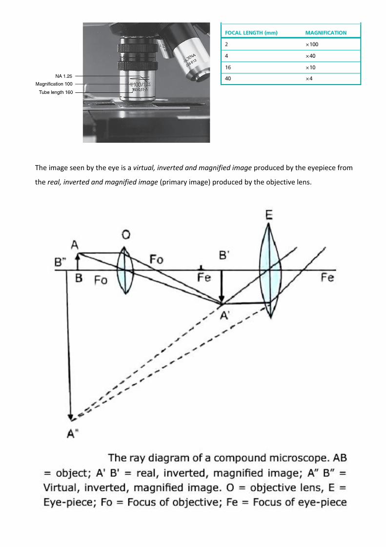
The image seen by the eye is a virtual, inverted and magnified image produced by the eyepiece from
the real, inverted and magnified image (primary image) produced by the objective lens.
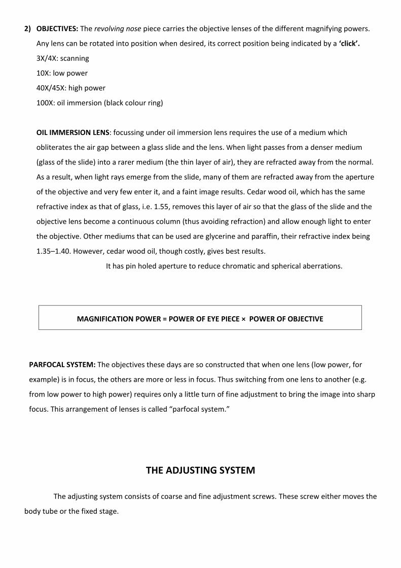
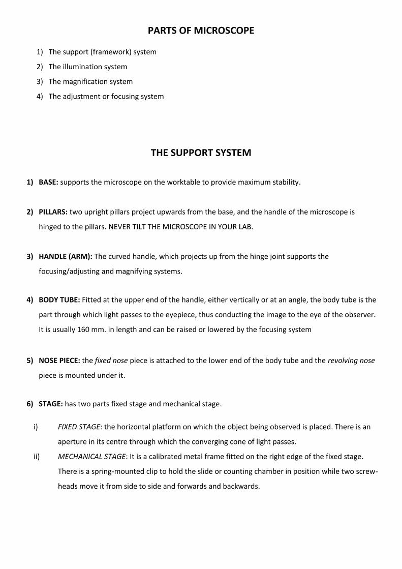
2) OBJECTIVES: The revolving nose piece carries the objective lenses of the different magnifying powers.
Any lens can be rotated into position when desired, its correct position being indicated by a ‘click’.
3X/4X: scanning
10X: low power
40X/45X: high power
100X: oil immersion (black colour ring)
OIL IMMERSION LENS: focussing under oil immersion lens requires the use of a medium which
obliterates the air gap between a glass slide and the lens. When light passes from a denser medium
(glass of the slide) into a rarer medium (the thin layer of air), they are refracted away from the normal.
As a result, when light rays emerge from the slide, many of them are refracted away from the aperture
of the objective and very few enter it, and a faint image results. Cedar wood oil, which has the same
refractive index as that of glass, i.e. 1.55, removes this layer of air so that the glass of the slide and the
objective lens become a continuous column (thus avoiding refraction) and allow enough light to enter
the objective. Other mediums that can be used are glycerine and paraffin, their refractive index being
1.35–1.40. However, cedar wood oil, though costly, gives best results.
It has pin holed aperture to reduce chromatic and spherical aberrations.
MAGNIFICATION POWER = POWER OF EYE PIECE × POWER OF OBJECTIVE
PARFOCAL SYSTEM: The objectives these days are so constructed that when one lens (low power, for
example) is in focus, the others are more or less in focus. Thus switching from one lens to another (e.g.
from low power to high power) requires only a little turn of fine adjustment to bring the image into sharp
focus. This arrangement of lenses is called “parfocal system.”
THE ADJUSTING SYSTEM
The adjusting system consists of coarse and fine adjustment screws. These screw either moves the
body tube or the fixed stage.

Looking from the side, and using the coarse
adjustment, bring the body tube down so that the low
power lens is about 0.5 cm above the slide, or high
power lens is about 0.5 mm above the slide (working
distance).
Now look into the eyepiece and gently raise the tube until the specimen comes into
focus. Do not bring the body tube down from any height while looking into the microscope. You might miss
the focusing position and continue moving it down thereby breaking the slide or permanently scratching
the objective lens.
Once the object is focussed using coarse adjustment, use fine adjustment. The cells and
their constituents are 3-dimensional structures and lie at different levels. Therefore, it is important not to
keep a field focus but to continuously “rack” the microscope by using fine adjustment after the specimen
has been brought under focus under any magnification.
It is a good practice to keep the fine adjustment screw in middle position before start
focussing the object.
OSPE CHECKLIST
1. Raise body tube, put the slide on the stage, and bring the object over the central aperture.
2. Choose the light source and type of mirror accordingly, bring the desired objective lens into position
3. Adjust the position of the condenser and iris diaphragm according to the objective used
4. Look from the side when lowering the body tube, bring it to working distance
5. Adjust the light and use coarse and fine adjustment screws.
6. Continuously Rack the microscope