microstructure-sensitive fatigue crack nucleation in a · web viewthe kinematic decomposition...
TRANSCRIPT

Microstructure-sensitive fatigue crack nucleation in a
polycrystalline Ni superalloy
V.V.C. Wan1*, J. Jiang1, D.W. MacLachlan2, F.P.E. Dunne1
1 Department of Materials, Imperial College, London, SW7 2AZ, UK2 Rolls-Royce plc,, PO Box 31, Derby, DE24 8BJ, UK
* Corresponding author: E-mail address: [email protected]
Large-grained polycrystalline Ni alloy RS5 has been tested in fatigue. Morphology and texture have
been characterised using EBSD and utilised to construct representative 3D finite element crystal
plasticity models. A stored energy criterion has been used to predict scatter in fatigue crack
nucleation life and the results compared with experimental findings. Good quantitative prediction of
experimental fatigue lives is obtained. The observed progressive increase in scatter with decreasing
strain range is captured. The stored energies for fatigue crack nucleation determined for Ni alloy RS5
and ferritic steel and were found to be 13,300J/m2 and 580J/m2 respectively, showing very good
consistency with the corresponding Griffith fracture energies of 48,700J/m2 for Ni alloy and
1,900J/m2 for ferritic steel.
Local microstructural variations are shown to influence corresponding grain-level stress-strain
response. At the microstructural level, purely elastic, reversed plastic and ratcheting behaviour are
all observed. In addition, plastic and elastic shakedown are also found to occur which depend upon
features of the microstructure and the nature of the applied loading. These phenomena all influence
fatigue crack nucleation.
Keywords: RS5 Ni Alloy, fatigue crack nucleation, crystal plasticity, polycrystal fatigue
1

1. Introduction
Nickel-based superalloys have been established as important refractory structural alloys in
engineering components due to their superior properties, such as high strength, high melting
temperature, excellent creep, corrosion and fatigue resistance and good damage tolerance. They
have been widely used in the energy and aero industries and turbine discs in gas turbines are
obvious examples. It is recognised that in order to improve these properties, strengthening of the
gamma matrix phase and gamma prime precipitates is essential. RS5 Ni alloy was introduced and
patented in 1994 [1] to provide particularly the higher strength, rupture, tensile and fatigue
properties over its predecessors RS1 and RS4 alloys. Studies then followed to improve the castability
and weldability of the superalloy such as by using thermally controlled solidification techniques [2,
3].
Current research in fatigue includes that focusing on mechanistic understanding of the role of
microstructural heterogeneity and its impact on behaviour. Studies include those on elastic
anisotropy, morphology and crystallography with respect to fatigue loading at different length scales
[4, 5]. The role of heterogeneities in the microstructure is important in fatigue life, particularly
relating to the process of crack nucleation, and further, in the context of microstructurally-sensitive
crack growth, and an alloy for which both are relevant is the large-grained RS5 Ni alloy. This alloy is
also known to show very considerable scatter in its fatigue life [1], which is argued to be related to
the natural variation in microstructure related to its very large grain size, and to result from the
heterogeneous microstructure. This phenomenon is not limited to nickel-based superalloys and is
commonly observed in many other coarse grained alloys and a further example is that of a ferritic
steel [6] for which it is very clear that the process of fatigue crack nucleation (as opposed to growth)
may consume a very significant fraction of the cycles to failure. As a consequence, the scatter in
fatigue life to crack nucleation is crucially important since it is safety-critical. The understanding of
the mechanistic basis of fatigue crack nucleation remains an important research topic, and recent
literature [7-9] has assessed a range of fundamental approaches, including those based on stored
energy, and which address the full detail of the local microstructural heterogeneity [6]. Stroh’s
nucleation theory [10] considers dislocation pile-ups and work hardening leading to energy storage,
and the stored energy was found to be proportional to applied plastic strain. The energy build-up
leading to crack nucleation was found to be appropriate to explain and predict the crack formation
[11-13]. Accumulated slip in cyclic loading generates persistent slip bands (PSBs) which lead to the
formation of extrusions and intrusions of slip on free surfaces. The energies associated with PSBs
have been the focus of some researchers and the failure criterion proposed by Sauzay et al. [14]
2
considered an energy balance for different surface types. Sangid et al. [15, 16] presented a model for
the total energy in a PSB necessary to nucleate grain-level cracks. Earlier studies considered the
accumulated slip linked to the development of PSBs in fatigue reported in [7] and this quantity has
also been used as a fatigue crack nucleation criterion [17], where a critical accumulation of slip is
required for failure. More recently, Sweeney et al. [18] considered a local strain energy parameter
and a critical constraint to be satisfied for failure to occur. However, Wan et al. [6] found that the
accumulated slip criterion alone was insufficient to address the experimentally observed scatter of
fatigue nucleation in their ferritic steel polycrystals. Instead they introduced a stored energy
criterion considering the statistically stored dislocation (SSD) and geometrically necessary dislocation
(GND) densities as a key measure for crack nucleation which introduced an activation volume and
consequently a critical energy rate for nucleation similar to a Griffith criterion. This approach has
been integrated with a Gibbs free-energy change by other authors [19] to accommodate for the
cyclic internal stored energy. Other more recent works modified the Gibbs free-energy parameter
[20, 21] by introducing an energy density function to accommodate for the dislocations that are lost
per unit area of the nucleated crack surface. These criteria [22, 23] showed some success in
capturing the fatigue life scatter.
It is generally recognised that crystal plasticity modelling of realistic microstructures enables the
capture of local stress and strain heterogeneity in a given microstructure with reasonable integrity,
e.g. [24]. Zhang et al. [25, 26] have utilised this approach to predict fatigue life based on the
statistical deviations of strain responses in a 3D volume element microstructure to represent their
polycrystalline bar. However, the cuboid representative models utilised were not able to replicate
the experimental morphologies and grain size distribution which may explain why surface crack
development on the specimens was not captured. Investigations including representative geometry
of notched coarse grained samples has been carried out in [27] which captures statistically the
fatigue scatter and recognises the existence of localised strain development, but does not explicitly
capture the detailed 3D representation of the alloy. Other modelling approaches based on ‘square’
grained meshing [28] have been used to try to quantify scatter in polycrystal fatigue. In addition to
explicit modelling of the microstructural morphology [5, 6], Voronoi tessellation cell structures
provide an alternative way to represent polycrystalline microstructures by assuming a crystallisation
process and grain growth from random points which collide to form grain boundaries [29]. An
example of a controlled Poisson Voronoi tessellation model which has been integrated into the
software system, VGrain [30, 31], has been demonstrated to be capable of generating 2D and 3D
grain structures representative of experimentally observed microstructures .
3

In this paper, we utilise a dislocation-based stored energy criterion [6] in order to model and predict
fatigue scatter generated from differing loading conditions and resulting from texture variation, and
assess its performance against independent experimental fatigue observations. Crystal plasticity
finite element modelling (CPFEM) is used to describe the local grain-level behaviour through to that
of the polycrystal, utilising a user-defined material subroutine (UMAT). A detailed 3D representative
microstructure using VGrain [30, 31] is generated with morphology based on that determined from
the experimental microstructures of RS5 Nickel superalloy measured by electron backscatter
diffraction (EBSD). The experimentally obtained fatigue test results are assessed against model
predictions for fatigue crack nucleation.
2. Experimental Data
RS5 polycrystal nickel based superalloy is considered in the fatigue crack nucleation study. The
microstructural model development using CPFEM is based on the experimental microstructural
characterization of RS5 samples obtained from EBSD. Experimental fatigue test result for RS5 alloy
are available for a number of loading conditions and provide information on fatigue life scatter
under the differing loading conditions presented.
2.1.RS5 characterisation
RS5 cast nickel based superalloy fatigue test samples were supplied by Rolls-Royce plc with the
geometry shown in Fig. 1(a). Three microscopy samples were machined and subsequently polished
using diamond suspension from 6μm to 3μm to 1μm and finished with oxide polishing suspension
(OPS) (~0.2μm). Prepared samples were then put into the electron scanning microscope to examine
their microstructures using EBSD. The EBSD maps of 5.35mm x 4.00mm with 20μm step size were
obtained. The detailed microstructure, grain morphology, texture and grain size distributions are
illustrated in Table 1, and a more focused region showing a representative EBSD map is shown in Fig.
1(b).
It is observed that the RS5 alloy presents a range of smooth to wavy coarse grain boundaries, but
there are no obvious twins present. Further, from the pole figures and texture information of the
three maps given in Table 1, the convolution frequency of [100], [011] and [110] shows the material
has minimal preferred crystallographic orientation. Considering the grain size distributions across all
three maps as illustrated in Table 1, the grain size varies significantly from small grains of ~ 50μm to
the largest observed grains of ~980μm. The mean grain size was determined to be ~690μm. With
this microstrutural information and statistical data, representative computationally comparable
4

models with microstructures representative of the alloy in terms of both texture and morphology
may be generated in order to perform detailed fatigue lifing studies.
2.2.Fatigue test data
The fatigue tests on the RS5 alloy were conducted by Rolls-Royce plc. with varied loading history and
strain ranges, and the results are summarised in Fig. 2 for tests carried out at 20 oC. The fatigue
variability at this temperature is observed to be large and can in principle be huge, whereas at higher
temperatures, oxidation and/or microstructure coarsening tend to limit this variability in this class of
Ni alloys. However, in the present study the fatigue scatter at a temperature of 20oC is of primary
interest, particularly in relation to its origin in microstructural heterogeneity from texture variation.
The fatigue test samples were cut from bar with dimensions as illustrated in Fig. 1(a), where uniaxial
strain-controlled loading was applied along the x-direction. The resulting test data may be used to
assess and rank the material performance under differing experimental test conditions. Examination
of the RS5 fatigue specimens tested to failure reveal fatigue crack nucleation and ultimately rupture
within the gauge length region of the bar.
Surface cracks are generally observed and are used to determine the onset of fatigue failure of
specimens at two sets of strain ratios (R=0 and R=-1) at 20oC as shown in Fig. 2. Maximum uniaxial
strains from 0.50% to 0.65% were applied with strain ratios of R=0 in the x-direction, and fully
reversed tests (R=-1) with maximum strains between 0.375% to 0.45% (0.75% to 0.90% strain range
respectively) are considered. For low-cycle fatigue tests, the number of cycles to nucleation is
commonly defined by a measured drop in maximum load which some authors have attempted to
correlate with crack length [32]. Here the number of cycles to 5% load drop is recorded, as well as
the number of cycles to fatigue rupture or failure in the RS5 specimens.
Evidently from Fig. 2, RS5 alloy exhibits significant scatter for the same strain ratios and strain
loading. Thirteen RS5 specimens were tested in which each microstructure is different, with seven
tested under R=-1 conditions and the remaining six under R=0 strain ratio. Note that the tests with
strain ranges greater than 0.70% were subjected to strain ratio R=-1, and below 0.70% to R=0 test
conditions. Under the load conditions specified, the majority of the fatigue lives recorded are
between 10,000 and 55,000 cycles. As expected, as maximum applied strain increases, so fatigue life
decreases. Under R=0 loading, a specimen tested with maximum strain of 0.65% showed cycles to
5% load drop and rupture to be 14,407 and 15,572 cycles respectively. However, scatter exists when
a number of tests are carried out under the same strain range as illustrated by the duplicate test(s)
with maximum strain of 0.375% and R=-1, where cycles to 5% load drop were recorded between
5

10,629 to 29,965 cycles, demonstrating large variation. In order to compare quantitatively the
scatter range with respect to the maximum and minimum cycles recorded for failure, a percentage
range (er) is introduced. The scatter range is determined for test data with more than one data point
under the same load condition using Eq. 1, where Nmax is the maximum and Nmin the minimum
cycles recorded under a specific load condition for failure.
er=100(N max−N min)
Nmax+N min
(1)
In this case, based on the three data points in Fig. 2 under a maximum strain of 0.375% applied at
R=-1 strain ratio, the average cycles (the average of the maximum and minimum values only) to 5%
load drop is 20,297 ± 9,668 cycles or ±48% (er). Similarly calculated, the number of cycles to fatigue
rupture is 33,619 ± 21,516 cycles or ±64%. Other load conditions with available scattered test data
from Fig. 2 are calculated and summarised in Table 2. Here, there is no common scatter range
observed under the load conditions studied, which reinforces the importance of recognising the role
of local microstructure in fatigue, and its implications for crack nucleation and growth. Therefore,
any mechanistically based fatigue crack nucleation criterion must be sensitive to the local
microstructure and micromechanics.
3. Geometric Model Generation
In order to investigate the experimental scatter data of RS5 alloy, Abaqus FE/CAE was used to
represent the detailed test sample microstructure in order to attempt to capture the experimentally
observed fatigue response of the superalloy, and particularly the scatter in fatigue life. VGrain is
used to generate a representative 3D grain morphology similar to that of the experimental
specimens, which is then meshed using Abaqus in the pre-processing stage. A crystal plasticity model
is embodied within a UMAT subroutine and calibrated for the RS5 Ni alloy behaviour. Microstructure
model integration through VGrain has been demonstrated previously [30] for which the process is
illustrated in Fig. 3, and is used here to develop the model for fatigue lifing analysis at the grain
length scale.
3.1.VGrain-generated test sample
Controlled Poisson Voronoi tessellation is utilised within VGrain developed by Zhang et al. [30, 31]. A
grain size distribution function e.g. mean grain size, standard distribution and skewness shown in
Table 1 was generated by VGrain to be representative of the experimental characterisation
6

presented above. The details of the formulation to determine the regular seed distances of grains
and the control parameter can be found in [31]; specifically the minimum, mean and maximum grain
sizes need to be specified, and the skewness of the grain size distribution function is measured by a
parameter defined as Pr in [30].
Based on the experimental characterisation of the RS5 alloy from Table 1, it was found that the
average minimum, mean and maximum grain sizes across three maps within the RS5 samples are
50μm, 690μm and 980μm respectively. The Pr value was set as 0.80 (or 80%) which gave a
distribution of normalised grain sizes as shown in Fig. 4(a). As presented in Table 1, differing alloy
RS5 EBSD maps are obtained in order to provide statistical information on the RS5 samples. The
grain size distributions and textures in three RS5 samples are shown and this information has been
used when constructing the RS5 representative polycrystalline models in Fig. 4. The model
representations of the grain size distributions and textures so measured have been shown to
reproduce the average polycrystal stress-strain behaviour within 2%, but no further statistical tests
have been carried out. Studies such as Przybyla et al. [33, 34] have proposed frameworks which
consider the extreme statistics of microstructural attributes (e.g. grain size, grain orientation, grain
misorientation, phase) which influences fatigue sensitive parameters to failure. Though these
coupled statistical parameters have been shown to capture the extreme value response of the
microstructure, it is recognized that to construct such extreme value distributions requires
significant simulation and experimental data to be considered statistically useful. The present study
investigates only the influence of crystallographic orientation realization over the same morphology,
in order to establish whether these microstructural attributes alone have significant influence on
failure giving rise to ranges in lifetime which represent experimental observations.
The geometric dimensions of the model sample were defined from Fig. 1(a). Experimentally
observed sample failure mostly occurs within the gauge length of the sample, and considering the
computational expense of modelling a complete to-scale model, only the middle region of the
experimental test sample was modelled with an appropriate length 6.4mm and a diameter of
6.4mm. The VGrain generated microstructure geometry was then read in to Abaqus CAE. The surface
grain morphology of the model containing 332 grains is illustrated in Fig. 4(b). A 3D microstructure
model as shown in Fig. 4(c) shows a very complex grain boundary network within the polycrystal
sample as anticipated. Abaqus meshing tools with mesh dependent on the grain morphology were
used, in which ten-noded tetrahedral elements (C3D10) with an average element size of ~40μm was
applied as shown in Fig. 4(d).
7

It is noted from the EBSD maps as shown in Table 1, that there appear to be exhibited small-scale
(<10μm) particles distributed within the microstructure due to the presence of carbides. In this
study, we focus on material physical behaviour at the grain length scale and these particles are not
explicitly modelled in our representative microstructure geometric model. It is likely that such
carbides have a role in slip localisation and in defect nucleation, and the same may be said of the
mild grain boundary serrations apparent in Fig. 1(b), which are also not explicitly included in the
geometric microstructural representation. However, it is argued that the uniformity of their
distribution and their length scale is such that they do not dominate the material fatigue response at
the grain scale; this is, however, controlled by crystallography, morphology and grain boundary
constraint which are captured in the modelling. Experimental characterisation indicates that
nucleating cracks are not directly associated with the small carbides present, and that most cracking
is transgranular in nature.
3.2.Crystal plasticity calibration and validation
The kinematic decomposition of the deformation gradientF can be expressed in terms of the elastic
F e and plastic F p tensors as described [35] such that
F=F e Fp.
(2)
The crystal plasticity model written in a UMAT subroutine, expresses the plastic velocity gradient Lp
in terms of slip rate γ, and system normal n and slip s directions as
Lp=F p F p−1=∑i=1
Ns
(γ in i⨂ si ) (3)
where N s is the number of active slip systems. The slip rate is given by [6, 36, 37]
γi=ρmSSD v ( bi )2 e
(−∆ H i
kT )sinh( (τ r
i−τci ) γ0 ∆ V
kT ), (4)
where v is the energy barrier jump frequency, b the Burger’s vector magnitude, ∆ H the Helmholtz
free energy, k the Boltzmann constant, T the temperature,∆ V the activation volume, τ r the
resolved shear stress and ρ indicates dislocation density. The accumulated slip evolving on each of
the 12 considered [111] <100> family face centred cubic (FCC) slip system is explicitly considered for
8

a Ni crystal. A Taylor dislocation based hardening on slip strength is adopted such that the resultant
slip strengths, or critical resolved shear stresses, are given by
τ ci=τ co
i+μGb√ ρSSD. (5)
The evolution of SSD density is taken to increase in proportion to the evolution of accumulated slip
for the purposes of simplicity and as expressed in a previous study [6].
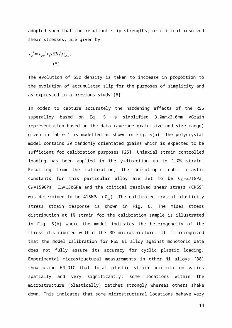
In order to capture accurately the hardening effects of the RS5 superalloy based on Eq. 5, a
simplified 3.0mmx3.0mm VGrain representation based on the data (average grain size and size
range) given in Table 1 is modelled as shown in Fig. 5(a). The polycrystal model contains 39 randomly
orientated grains which is expected to be sufficient for calibration purposes [25]. Uniaxial strain
controlled loading has been applied in the y-direction up to 1.0% strain. Resulting from the
calibration, the anisotropic cubic elastic constants for this particular alloy are set to be C11=271GPa,
C12=150GPa, C44=130GPa and the critical resolved shear stress (CRSS) was determined to be 415MPa
(τ co). The calibrated crystal plasticity stress strain response is shown in Fig. 6. The Mises stress
distribution at 1% strain for the calibration sample is illustrated in Fig. 5(b) where the model
indicates the heterogeneity of the stress distributed within the 3D microstructure. It is recognized
that the model calibration for RS5 Ni alloy against monotonic data does not fully assure its accuracy
for cyclic plastic loading. Experimental microstructural measurements in other Ni alloys [38] show
using HR-DIC that local plastic strain accumulation varies spatially and very significantly; some
locations within the microstructure (plastically) ratchet strongly whereas others shake down. This
indicates that some microstructural locations behave very differently to the macroscale, average
response, and yet no detailed microstructural measurements of hysteresis and Bauschinger effects
have yet been made in order to test modelling capability. However, crystal plasticity models have
been shown capable of capturing the progressive microstructural ratcheting taking place [39] giving
some confidence that the hysteresis response is also captured.
Independent fatigue lifing studies [25, 29] have utilised similar volume element samples to that
shown in Fig. 5 to represent a finite volume within their experimental fatigue specimens. However,
in the present work, a statistically representative model is developed as shown in Fig. 4 in order to
address fatigue scatter and lifing resulting from microstructural variation such that boundary effects
are likely to be small.
4. Fatigue Analyses
9

In order to capture the statistical variation of differing microstructures, we assigned three different
sets of random crystallographic orientations (which we term ‘realisations’) but maintained the same
morphological features (i.e. grain shape, and size distribution function). The cyclic loading was
applied in the sample axial z-axis direction shown in Fig. 4. Similar to the experiments, a strain ratio
R=0 was applied with maximum strains of 0.50%, 0.55% and 0.65%, and a strain ratio R=-1 with
maximum strains of 0.375%, 0.40% and 0.45% (strain ranges of 0.75%, 0.80% and 0.90%
respectively). The simulated fatigue samples are subjected to 5 cycles of strain controlled loading.
Jiang et al. [40] have shown in their fatigue tests that even a relatively small number of cycles may
be adequate to allow the local development of dislocation densities and networks of stresses and
accumulated strain in the microstructure which do not necessarily change significantly with
subsequent cycles in a spatial sense. In addition, Wan et al. [6] showed that with a progressively
developing field of slip and dislocation accumulation, plastic shakedown occurs enabling sensible
extrapolations to be made over subsequent cycling.
Fig. 7 shows the macro stress strain response of the polycrystal model under strain ratios of R=0 (Fig.
7(a)) and R=-1 (Fig. 7(b)) with the strain ranges shown. The straining during the first cycle for each
strain range is demonstrated to be such that the elastic limit is exceeded as plastic deformation and
hardening is witnessed macroscopically for all load conditions applied. Thereafter, i.e. for the second
and subsequent cycles for each strain range, the cyclic hysteresis loops illustrate that elastic
shakedown appears to occur, at least at the macro-scale average level.
The accumulation of slip has been used successfully as the indicator of the location of crack
nucleation by a number of authors including [24, 37], and in this way, three hotpot sites for crack
nucleation are identified on the tubular surface in each of the 3 realisation of the sample models. A
total of nine potential initiation hotpots are closely monitored.
Fig. 8 shows the Mises stress distributions for R=0 straining with maximum applied strain of 0.50%
for the three crystallographic realisations; that is the three samples with differing assigned
crystallographic orientations. It is evident that the differing crystallographic orientation distributions
generate quite different stress heterogeneity within each of the three samples. This is further
highlighted by the different locations of nucleation hotspots identified (on the basis of high slip
accumulation) such as in sample no. 1 - Fig. 8(a); the three hotspots A, B and C are all found on the
top surface along grain boundaries compared to sample no. 2 (Fig. 8(b)) and sample 3 (Fig. 8(c)),
where all hotspots were also found along or in close proximity to grain boundaries but in different
locations and grains. The extraction of micromechanical behaviour at the hotspots is carried out
using finite element Gauss point data. Fig. 9 shows the stress-strain response at (the differing)
10

hotspots ‘C’ for each sample during five fatigue cycles at the applied maximum strains shown for
strain ratio R=0 for (a), (b) and (c) and for strain ratio R=-1 in (d), (e) and (f).
For strain ratio of R=0 (Figs. 9(a-c)), it is evident that with increasing applied maximum strain from
0.50% to 0.65%, greater plastic strains develop and also that elastic or plastic shakedown is seen to
occur depending on the sample examined. For example, in Fig. 9(b), under the same applied strain
conditions in all three samples (green, blue and black lines) elastic shakedown behaviour is seen for
one sample at the hotspot, whereas another sample hotspot experiences continued reversed
plasticity but without further ratcheting and therefore shows plastic shakedown. For strain ratio R=-
1, with increasing applied straining, Fig. 9(d-e), fully reversed cyclic plasticity is captured. The cyclic
hardening behaviours are found to be very different for all three samples, and this emphasizes the
fact that differences in crystallographic orientation and hence texture not only influence the location
of high slip accumulation and potentially crack nucleation location, but also likely greatly influences
the resulting number of cycles necessary to cause fatigue crack nucleation. The fatigue variability of
this alloy results from contributions of elastic mismatch strains (because of the elastic anisotropy),
but predominantly from the localisation of slip. The latter is influenced initially by the elastic
anisotropy, but as plastic strain accumulation becomes larger, these influences reduce in
importance. While the strain accumulation per cycle may not be that large, over numbers of cycles
with ratcheting, the plastic strain accumulation is such that the initial effects of elastic anisotropy
become ‘washed out’. The crystal plasticity modelling has demonstrated that after just five fatigue
cycles, local hysteresis loop stabilization has been realised at the microstructural level (eg, in Fig. 9).
Experimental measurements in other Ni alloys [38] also indicate that microstructure-level
stabilisation occurs.
4.1.Development of fatigue crack nucleation
The stored energy criterion for fatigue crack nucleation developed by Wan et al. [6] is closely
associated with the localisation of slip and the density magnitudes of SSDs and GNDs which are
argued to play a significant role in developing the highly localised stress states and contributing to
the local stored energy and the localised cleavage. Explicit determination of full-field SSD
distributions and stored energy associated with material slip is available from the crystal model. Wan
et al. [6] have shown that in the large grained ferritic steel microstructures considered, SSD density
development is significantly more substantial than that from the accumulation of GND density.
Hence due to the coarse grained structure in the RS5 alloy, we argue that the GND density is unlikely
to be significant with respect to that from statistically stored dislocations and hence that the SSD
density dominates (over that of GNDs) the localised development of stored energy. As a result, the
11

GND density is neglected in this study and the stored energy criterion [6] to determine fatigue
nucleation life is written as
Gcrit=G N f ,
(6)
where Gcrit is the critical stored energy for crack nucleation calculated from the number of cycles to
fatigue crack nucleation N f and the rate of steady state stored energy accumulation, G, which can
be expressed as
G=U ∆ V s
∆ A s=∮
c
❑ σ :d ε p
√ρSSD .
(7)
The fraction of the plastic energy associated with energy storage is the fraction which is assigned a
value of 0.05. The stored energy criterion is used to study and explain the scatter observed in the
RS5 alloy as shown in Fig. 2.
Fig. 10(a) shows the evolution of effective stress against the accumulated slip for sample no. 1 at
hotspot ‘C’. After the first cyclic straining the rate of evolution of accumulated slip achieves a steady
state early in the cyclic life. As seen in Fig. 10(b) the evolution of SSD density similarly reaches a
steady state of growth across all three hotspots in Sample no. 1. Evaluating the remaining
realisations of samples simulated and determining the energy stored per cycle at the fatigue
hotspots (Eq. 7), the inverse energy rate, which is proportional to the number of cycles to crack
nucleation, evident from Eq. 6) G−1, is shown in Fig. 11.
From Fig. 11(a), the model predictions suggest significant variation in energy stored per cycle in all
hotspots identified in the three samples. At higher strain range, tighter variation is seen in the
models, as opposed to the low strain range of 0.50% which shows much greater variation of G−1
obtained. It is noted that the G−1 parameter presents the number of cycles per joule of energy
stored at the hotspot, such that lower strain range leads to a greater number of cycles required to
store the same level of energy hypothesised to nucleate a crack. Considering only the hotspot with
highest rate of stored energy in each of the three samples for each strain range simulated, we show
the scatter range for the strains considered as illustrated on Fig. 11(b) resulting solely from the
differing microstructural texture realisations. The scatter band range reduces much more
significantly with increasing strain range and this band follows lifing curves similar to those typically
found in experimental fatigue tests. Using data from Fig. 11(a), the average stored energy rate,
12

calculated similarly to that for experimental cycles to 5% load drop and rupture in Table 2, is noted
in Table 3 where the range of stored energy rate (using Eq. 1) is also calculated.
Tests with strain ranges of 0.5% to 0.9% (see Table 3) show an average stored energy rate of 0.109
to 1.885 J/m2 cycle-1 respectively. The considerable range of stored energy per cycle is followed by a
decreasing scatter band from ± 57% to ± 8%. This would indicate that at higher strain ranges the
development of energy stored in each of the different locations of hotspot show similar rate of
stored energy quantitatively, even when different realisations of crystallography are distributed in
the microstructure samples. The convergence of energy stored per cycle at high plastic deformations
could support the hypothesis of reaching dislocation saturation such that the stored energy
consequently accumulates to a common critical stored energy density rate for nucleation.
In low-cycle fatigue tests, some authors have attempted to correlate crack length [32] with the
measured relative drop in maximum load. More commonly some would refer the number of cycles
to nucleation to a percentage drop in maximum load. Hence in the following, we define the
experimental cycles to 5% load drop data in Fig. 2 as the number of cycles to nucleation ( N f ) to
address the scatter witnessed from experimental fatigue test data. From Table 3, the predicted
range of stored energy rate per cycle and the known experimentally observed cycles to nucleation
(Fig. 2) are used to obtain the critical stored energies (Gcrit ) using Eq. 6 in order to provide the
strongest consistency across the experimental fatigue life data. This is presented in the last column
in Table 3 and shows that a range of critical stored energies is obtained. In principle, a single, unique
value is anticipated (independent of strain range and R-ratio) to provide the definitive material
property for fatigue crack nucleation. However, because of experimental scatter and uncertainty in
relation to the use of the 5% load drop measure to define nucleation, this remains an aspiration.
Hence we take the average critical stored energy (Gcrit,avg) to be the definitive energy for fatigue crack
nucleation which gives a value of Gcrit,avg = 13,344J/m2 within a range of 18%.
This critical stored energy Gcrit,avg is then utilised to predict the cycles to fatigue crack nucleation for
the three sample microstructural realisations for the range of applied strain loading and results are
plotted against the experimental fatigue test data extracted from Fig. 2 and are shown in Fig. 12. The
range of predicted scatter (dashed lines in Fig. 12) for fatigue crack nucleation is also shown, which
originates solely from the texture variation considered in the three microstructural realisations. The
stored energy criterion therefore gives a predicted scatter band on fatigue life which captures ~50%
of the observed experimental cycles. Some of the experimental observations lie outside of the
predicted range, but we note again that the stored energy criterion aims to establish crack
nucleation. The experimental data shown, however, are those for 5% load drop and it is therefore
13
anticipated that the experimentally measured cycles will generally exceed those predicted by the
model.
It is argued that the critical stored energy rate for fatigue crack nucleation presented in this work
and in [6] is representative of the Griffith fracture energy for plasticity-enhanced fracture. The
critical stored energy to fatigue crack nucleation of ferritic steel was determined and published
previously to be 580J/m2 [6]. The fracture toughness (K IC) of a material in plane stress mode I crack
opening is related to the fracture energy G IC by K IC=√ E GIC, where E is Young’s Modulus.
Engineering alloys such as those of nickel have a representative fracture toughness of 100MPa.m0.5
[41] and ferritic steel was commented to have toughness 20MPa.m0.5 [42]. The modulus of Ni and
ferritic steel are taken to be 205GPa and 206GPa [37] respectively, thus giving a fracture energy (G IC
) of 48,700J/m2 for Ni alloy and 1,900J/m2 for ferritic steel. We note that the critical stored energies
for fatigue crack nucleation determined in this paper for RS5 Ni alloy and that in [6] for ferritic steel
are 13,300J/m2 and 580J/m2 respectively, thus providing a reassuring consistency with Griffith
fracture energies.
Optical investigations of the RS5 test pieces conducted at Rolls-Royce revealed mostly surface-based
crack nucleation which is largely transgranular though with some evidence also of intergranular
cracking, with persistent slip band formation thought to be the main driving mechanism. It is
thought nucleation is also possibly linked to near-surface porosity and interdendritic eutectic phases.
Crack nucleation does not seem to occur at carbides or inclusions. Early crack growth was found to
be smooth and facetted and likely to be influenced by crystallography. These observations support
the grain-level length scale chosen for the computational crystal plasticity study and the neglecting
of explicit representation of the carbide particles. They also reinforce the role of crystallography and
slip localisation in crack nucleation in alloy RS5 which have been the primary focus of this study of
scatter in fatigue crack nucleation.
14

5. Conclusions
Finite element crystal plasticity modelling has been used to investigate the deformation and fatigue
response of RS5 polycrystalline Ni alloy. Experimental microstructures have been characterised using
EBSD to provide morphological and texture information which is used to develop microstructurally
representative crystal plasticity models.
Predicted test sample macroscale response is found to show cyclic elastic-plastic behaviour in early
cycles but to quickly lead to elastic shakedown. However, at the microstructural level, a range of
material responses is observed including that which is purely elastic, together with cyclic plasticity,
ratcheting, plastic and elastic shakedown.
A stored energy criterion is used to investigate and predict fatigue crack nucleation in RS5 Ni alloy.
At higher strain ranges up to 0.90%, greater energy is stored at fatigue ‘hotspots’ and it has been
demonstrated that the predicted microstructural range of stored energy at fatigue hotspots
decreases with increasing applied strain range, giving rise to scatter in fatigue life of only ±8%. At
lower strain ranges, however, the predicted range of fatigue life scatter increases such that for
applied cyclic straining of 0.5%, scatter of ±57% on life is found. The stored energy criterion gives
quantitative prediction of fatigue crack nucleation life and of the fatigue scatter found in the
experiments resulting from microstructural variation. The stored energies determined for Ni alloy
RS5 and ferritic steel and were found to be 13,300J/m2 and 580J/m2 respectively, showing very good
consistency with the corresponding Griffith fracture energies of 48,700J/m2 for Ni alloy and
1,900J/m2 for ferritic steel.
Acknowledgements
This work is part of a Collaborative R&T Project, SILOET II, Project 10, Virtual Engine Design System,
supported by the Technology Strategy Board and carried out by Rolls-Royce plc and Imperial College
London. The authors would also like to express their gratitude to Dr. W. Li for providing the RS5 Ni
sample and experimental fatigue test data, Prof. J. Lin and Dr. D. Balint for providing access to
VGrain software.
15

References
[1] R.G. Snider, Nickel base alloys for castings, in, U.S. Patent No. 5,330,711. 19 Jul. 1994.[2] L. Nastac, J. Valencia, M. Tims, F. Dax, Advances in the Solidification of IN718 and RS5 Alloys, Superalloys 718, 625, 706 and Various Derivatives, (2001).[3] M. Gambone, S. Shendye, P. Andrews, W. Chen, M. Gungor, J. Valencia, M. Tims, Properties of RS 5 and other superalloys cast using thermally controlled solidification, in: Ninth International Symposium on Superalloys, 2000, pp. 161-170.[4] C. Robert, N. Saintier, T. Palin-Luc, F. Morel, Micro-mechanical modelling of high cycle fatigue behaviour of metals under multiaxial loads, Mechanics of Materials, 55 (2012) 112-129.[5] C. Sweeney, W. Vorster, S. Leen, E. Sakurada, P. McHugh, F. Dunne, The role of elastic anisotropy, length scale and crystallographic slip in fatigue crack nucleation, Journal of the Mechanics and Physics of Solids, 61 (2013) 1224-1240.[6] V.V.C. Wan, D.W. MacLachlan, F.P.E. Dunne, A stored energy criterion for fatigue crack nucleation in polycrystals, International Journal of Fatigue, 68 (2014) 90-102.[7] D.L. McDowell, F.P.E. Dunne, Microstructure-sensitive computational modeling of fatigue crack formation, International Journal of Fatigue, 32 (2010) 1521-1542.[8] F.P.E. Dunne, Fatigue crack nucleation: Mechanistic modelling across the length scales, Current Opinion in Solid State and Materials Science, (2014).[9] M.D. Sangid, The physics of fatigue crack initiation, International Journal of Fatigue, 57 (2013) 58-72.[10] A.N. Stroh, A Theoretical Calculation of the Stored Energy in a Work-Hardened Material, Proceedings of the Royal Society A: Mathematical, Physical and Engineering Sciences, 218 (1953) 391-400.[11] A.N. Stroh, The Formation of Cracks as a Result of Plastic Flow, Proceedings of the Royal Society A: Mathematical, Physical and Engineering Sciences, 223 (1954) 404-414.[12] K. Tanaka, T. Mura, A dislocation model for fatigue crack initiation, Journal of Applied Mechanics, 48 (1981) 97-103.[13] T. Mura, Y. Nakasone, A theory of fatigue crack initiation in solids, Journal of Applied Mechanics, 57 (1990) 1-6.[14] M. Sauzay, P. Gilormini, Influence of surface effects on fatigue of microcracks nucleation, Theoretical and Applied Fracture Mechanics, (2002) 53-62.[15] M.D. Sangid, H.J. Maier, H. Sehitoglu, A physically based fatigue model for prediction of crack initiation from persistent slip bands in polycrystals, Acta Materialia, 59 (2011) 328-341.[16] M.D. Sangid, H.J. Maier, H. Sehitoglu, An energy-based microstructure model to account for fatigue scatter in polycrystals, Journal of the Mechanics and Physics of Solids, 59 (2011) 595-609.[17] A. Manonukul, F.P.E. Dunne, High- and low-cycle fatigue crack initiation using polycrystal plasticity, Mathematical, Physical and Engineering Sciences, 460 (2004) 1881-1903.[18] C. Sweeney, B. O’Brien, F. Dunne, P. McHugh, S. Leen, Strain-gradient modelling of grain size effects on fatigue of CoCr alloy, Acta Materialia, 78 (2014) 341-353.[19] M. Naderi, M. Amiri, N. Iyyer, P. Kang, N. Phan, Prediction of fatigue crack nucleation life in polycrystalline AA7075-T651 using energy approach, Fatigue & Fracture of Engineering Materials & Structures, (2015) n/a-n/a.[20] M.E. Fine, S.P. Bhat, A model of fatigue crack nucleation in single crystal iron and copper, Materials Science and Engineering: A, 468 (2007) 64-69.[21] S.P. Bhat, M.E. Fine, Fatigue crack nucleation in iron and a high strength low alloy steel, Materials Science and Engineering: A, 314 (2001) 90-96.[22] L. Li, L. Shen, G. Proust, Fatigue crack initiation life prediction for aluminium alloy 7075 using crystal plasticity finite element simulations, Mechanics of Materials, 81 (2015) 84-93.[23] R. Voothaluru, C.R. Liu, A crystal plasticity based methodology for fatigue crack initiation life prediction in polycrystalline copper, Fatigue & Fracture of Engineering Materials & Structures, 37 (2014) 671-681.
16

[24] F.P.E. Dunne, A.J. Wilkinson, R. Allen, Experimental and computational studies of low cycle fatigue crack nucleation in a polycrystal, International Journal of Plasticity, 23 (2007) 273-295.[25] K.-S. Zhang, J.W. Ju, Z. Li, Y.-L. Bai, W. Brocks, Micromechanics based fatigue life prediction of a polycrystalline metal applying crystal plasticity, Mechanics of Materials, 85 (2015) 16-37.[26] K.-S. Zhang, Y.-K. Shi, J.W. Ju, Grain-level statistical plasticity analysis on strain cycle fatigue of a FCC metal, Mechanics of Materials, 64 (2013) 76-90.[27] D. Leidermark, D. Aspenberg, D. Gustafsson, J. Moverare, K. Simonsson, The effect of random grain distributions on fatigue crack initiation in a notched coarse grained superalloy specimen, Computational Materials Science, 51 (2012) 273-280.[28] O.J. McCarthy, J.P. McGarry, S.B. Leen, The effect of grain orientation on fretting fatigue plasticity and life prediction, Tribology International, (2013).[29] M. Rocha, E. Brühwiler, A. Nussbaumer, Microstructural influence on the scatter in the fatigue life of steel reinforcement bars, International Journal of Fatigue, 75 (2015) 205-212.[30] P. Zhang, D. Balint, J. Lin, An integrated scheme for crystal plasticity analysis: Virtual grain structure generation, Computational Materials Science, 50 (2011) 2854-2864.[31] P. Zhang, M. Karimpour, D. Balint, J. Lin, Three-dimensional virtual grain structure generation with grain size control, Mechanics of Materials, 55 (2012) 89-101.[32] R. Brommesson, M. Ekh, M. Hörnqvist, Correlation between crack length and load drop for low-cycle fatigue crack growth in Ti-6242, International Journal of Fatigue, 81 (2015) 1-9.[33] C.P. Przybyla, Microstructure-sensitive extreme value probabilities of fatigue in advanced engineering alloys, in: Materials Science and Engineering, Georgia Institute of Technology, 2010, pp. 328.[34] C.P. Przybyla, D.L. McDowell, Microstructure-sensitive extreme value probabilities for high cycle fatigue of Ni-base superalloy IN100, International Journal of Plasticity, 26 (2010) 372-394.[35] E.H. Lee, Elastic-Plastic Deformation at Finite Strains, Journal of Applied Mechanics, 36 (1969) 1-6.[36] F.P.E. Dunne, D. Rugg, A. Walker, Lengthscale-dependent, elastically anisotropic, physically-based hcp crystal plasticity: Application to cold-dwell fatigue in Ti alloys, International Journal of Plasticity, 23 (2007) 1061-1083.[37] C.A. Sweeney, W. Vorster, S.B. Leen, E. Sakurada, P.E. McHugh, F.P.E. Dunne, The role of elastic anisotropy, length scale and crystallographic slip in fatigue crack nucleation, Journal of the Mechanics and Physics of Solids, 61 (2013) 1224-1240.[38] T. Zhang, J. Jiang, B.A. Shollock, T.B. Britton, F.P. Dunne, Slip localization and fatigue crack nucleation near a non-metallic inclusion in polycrystalline nickel-based superalloy, Materials Science and Engineering: A, 641 (2015) 328-339.[39] T. Zhang, J. Jiang, T.B. Britton, B.A. Shollock, F.P. Dunne, Crack nucleation from combined crystal plasticity modelling, HR-DIC and HR-EBSD in superalloy containing non-metallic inclusions under fatigue, Proc. R. Soc. Lond., In Press (2016).[40] J. Jiang, J. Yang, T. Zhang, F.P.E. Dunne, T.B. Britton, On the mechanistic basis of fatigue crack nucleation in Ni superalloy containing inclusions using high resolution electron backscatter diffraction, Acta Materialia, 97 (2015) 367-379.[41] M. Ashby, Materials selection in conceptual design, Materials Science and Technology, 5 (1989) 517-525.[42] H.-J. Schindler, Fracture Toughness of Ferritic Steels: Lower Bounds and their Implications on Testing and Application, Procedia Engineering, 86 (2014) 247-257.
17(b)(a)

Figure 1 – (a) Dimensions of fatigue test specimens and (b) close-up EBSD map of region highlighted in Table 1
– Map no. 3 with orientation figure shown.
Figure 2 – Strain range applied vs cycles to failure of RS5 alloy at 20oC (provided by Rolls-Royce plc.)
Figure 3 – Illustration of the modelling process and analysis
18

Figure 4 – Pre-processing of model illustrating (a) distribution of grains against normalised grain size (b) surface
grain morphology (c) 3D network of internal and external grain boundaries (d) the tetrehedral element
meshed model.
Figure 5 – (a) Grain morphology of RVE model used for calibration (b) von Mises stress distribution (MPa) at
1.00% strain
Figure 6 – Calibrated CPFEM response against experimental macroscopic stress strain response
19

Figure 7 – Macroscopic stress strain response in the z-direction under (a) R=0 strain ratio and (b) R=-1
Figure 8 – Distributions of Mises stress after 5 fatigue cycles at R=0 and 0.50% strain in (a) Sample No. 1 (b)
Sample No. 2 (c) Sample No. 3, over the same morphologies of grains. Shown identified are three (A, B & C)
nucleation hotspots where high accumulation of slip is illustrated with black arrows for each sample. Note:
Some nucleation hotspots are not visible in the figures as they may be located on the hidden surface of the 3D-model. The
contours represent stress range from ~20MPa (blue) to 800MPa (red).
20

Figure 9 – Stress component ZZ vs strain ZZ at hotspot ‘C’ in samples No. 1, 2 & 3 after 5 fatigue cycles for R=0
strain ratio with max. strains of (a) 0.50%, (b) 0.55%, (c) 0.65%, and R=-1 strain ratio and max. strains of (d)
0.375%, (e) 0.40%, (f) 0.45%
Figure 10 – Evolution of (a) ZZ stress (loading direction) against accumulated slip at hotspot ‘C’ and (b)
statistically stored dislocation density across all 3 hotspots in sample No. 1 at R=0 and max. strain of 0.65%
over 5 fatigue cycles
21
Figure 11 – (a) Applied strain range vs the predicted number of cycles per Joule of energy stored at all 3
hotspots and 3 samples and (b) applied strain range vs number of cycles per Joule of energy stored based only
on the hotspot with the maximum accumulated slip for each of the three samples
Figure 12 – Applied strain range against cycles to crack nucleation for RS5 Ni alloy including: predicted cycles to
nucleation (black symbols), and predicted range based on the energy criterion for crack nucleation for the
three microstructural realisations showing microstructure sensitivity (dashed lines), and the experimental data
to 5% load drop and rupture.
22

Table 1 – Three EBSD measured inverse pole figures generated with respect to the horizontal axis and
corresponding pole figures and histogram plots of the grain size distributions.
23

Table 2 – Summary of fatigue scatter witnessed based on average cycles from experiment data
Table 3 – Summary of energy stored per cycle scatter based on average stored energy rate from the maximum
accumulation of slip (maximum hotspot) in the three realisation samples
24