microwave engineering unit 4
TRANSCRIPT
DEPARTMENT OF ELECTRONICS & COMMUNICATION ENGINEERING
MICROWAVE ENGINEERING
1
UNIT 4

DEPARTMENT OF ELECTRONICS & COMMUNICATION ENGINEERING
2
• HF 0.003 GHz to 0.030GHz• VHF 0.030 GHz to 0.3GHz• UHF 0.3 GHz to 1 GHz
(420-450MHz - P Band; Mobile Application : 890-945 MHz)
• L Band 1-2 GHz (1 – 2.6 GHz)• S Band 2-4 GHz (2.6 – 3.95 GHz)• C Band 4-8 GHz ( C : 3.95-5.85 & J: 5.85-8.2 ) • X Band 8-12 GHz ( 8.2 – 12.4 GHz)• Ku Band 12-18 GHz (12.4 – 18 GHZ)• K Band 18- 27 GHz (18 to 26.5 GHz)• Ka Band 27-40 GHz (26.5 – 40 GHz )• Millimeter 40-300 GHz ( W band 75 to 110 GHz)• Submillmeter above 300 GHz
Microwave Frequencies
DEPARTMENT OF ELECTRONICS & COMMUNICATION ENGINEERING
3
Microwave Applications
• Radars : Missile-tracking radars, Weather – detecting radars, Fine-control radars, Missile-guidance radar, Air-traffic control Radars
• Long Distance Communication such as TV, telemetry communication, Microwave Relay stations etc
• Radio Astronomical research of Space • Microwave receivers are used in radio astronomy to study and detect the
electromagnetic radiations from sun and stars.
• Commercial & Industrial Applications as Microwave oven(2.45 GHz and 600 watts)Drying Machines( Textile, food and paper industry)Biomedical applications(Deep electromagnetic heating for treatmentof cancer, electromagnetic transmission through human body hasbeen used for monitoring of heart beat, lung water detection etc.
•
DEPARTMENT OF ELECTRONICS & COMMUNICATION ENGINEERING
4
Microwave Crossed-Field Tubes
• In these tubes the DC Magnetic field and DC Electric field areperpendicular to each other. i.e., DC magnetic field plays a direct role inthe RF interaction process.
• They are also called M-type Tubes.
• In these tubes, the electrons emitted by the cathode are accelerated bythe electric field and gain velocity, but greater their velocity, the more
their path is bent by the magnetic field.
• If an RF field is applied to the anode circuit, those electrons entering thecircuit during the retarding field are decelerated, and give up some oftheir energy to the RF field.
• Consequently, their velocity is decreased, and these slower electronics willthen travel the DC electric field far enough to regain essentially samevelocity as before.
DEPARTMENT OF ELECTRONICS & COMMUNICATION ENGINEERING
5
• Because of the crossed field interactions, only those electrons that havegive up sufficient energy to the RF field can travel all the way to theanode.
• This phenomenon would make the M-type tubes relatively efficient.• Those electrons entering the circuit during the accelerating field are
accelerated by means of receiving enough energy from the RF field andare returned back towards the cathode.
• This back-bombardment of the cathode produces heat in the cathodeand decreases the operational efficiency.
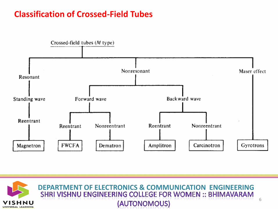
• The Classification of crossed field tubes are given below.
DEPARTMENT OF ELECTRONICS & COMMUNICATION ENGINEERING
6
Classification of Crossed-Field Tubes
DEPARTMENT OF ELECTRONICS & COMMUNICATION ENGINEERING
7
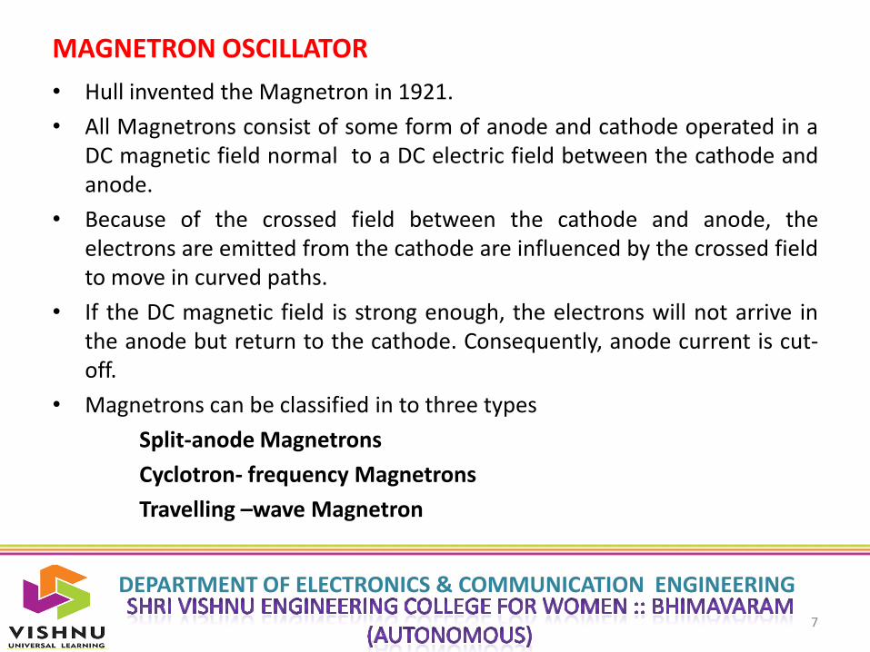
MAGNETRON OSCILLATOR
• Hull invented the Magnetron in 1921.
• All Magnetrons consist of some form of anode and cathode operated in aDC magnetic field normal to a DC electric field between the cathode andanode.
• Because of the crossed field between the cathode and anode, theelectrons are emitted from the cathode are influenced by the crossed fieldto move in curved paths.
• If the DC magnetic field is strong enough, the electrons will not arrive inthe anode but return to the cathode. Consequently, anode current is cut-off.
• Magnetrons can be classified in to three types
Split-anode Magnetrons
Cyclotron- frequency Magnetrons
Travelling –wave Magnetron
DEPARTMENT OF ELECTRONICS & COMMUNICATION ENGINEERING
8
• A) Split-anode Magnetrons: This type of a magnetron uses a static negativeresistance between the two anode segments. It operates at a frequenciesbelow the microwave region.
• B) Cyclotron- frequency Magnetrons: This type operates under theinfluence of synchronism between an alternating component of the electricfield and a periodic oscillation of electrons in a direction parallel to the field.It operates at a frequencies in microwave range, but their power output isvery small ( about 1 w at 3GHz), and their efficiency is very low.
• Travelling –wave Magnetron : This type depends on the interaction ofelectrons with a travelling electromagnetic field of linear velocity. They areclassified as
Cylindrical Magnetron Linear Magnetrons
Coaxial Magnetron Voltage-tunableMagnetronInverted coaxial Magnetron Frequency-agileMagnetron

DEPARTMENT OF ELECTRONICS & COMMUNICATION ENGINEERING
9
Cylindrical Magnetron :
DEPARTMENT OF ELECTRONICS & COMMUNICATION ENGINEERING
10
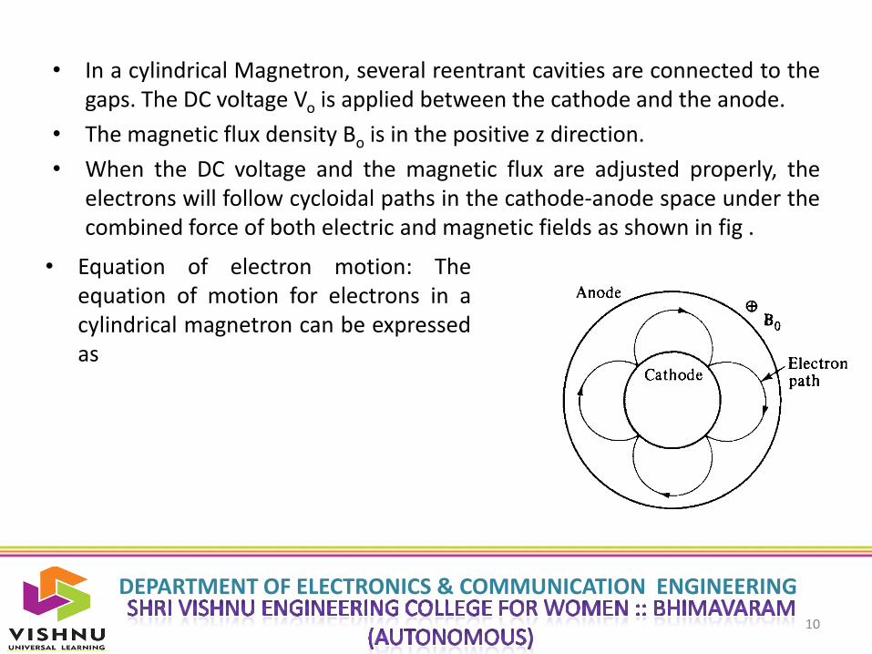
• In a cylindrical Magnetron, several reentrant cavities are connected to thegaps. The DC voltage Vo is applied between the cathode and the anode.
• The magnetic flux density Bo is in the positive z direction.
• When the DC voltage and the magnetic flux are adjusted properly, theelectrons will follow cycloidal paths in the cathode-anode space under thecombined force of both electric and magnetic fields as shown in fig .
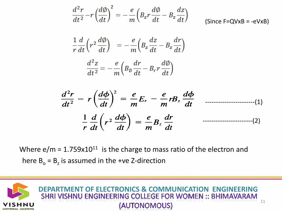
• Equation of electron motion: Theequation of motion for electrons in acylindrical magnetron can be expressedas
DEPARTMENT OF ELECTRONICS & COMMUNICATION ENGINEERING
11
Where e/m = 1.759x10¹¹ is the charge to mass ratio of the electron and
here Bo = Bz is assumed in the +ve Z-direction
(Since F=QVxB = -eVxB)
-----------------------(2)
-----------------------(1)
DEPARTMENT OF ELECTRONICS & COMMUNICATION ENGINEERING
12
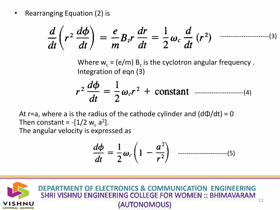
• Rearranging Equation (2) is
Where wc = (e/m) Bz is the cyclotron angular frequency .Integration of eqn (3)
-----------------------(3)
-----------------------(4)
At r=a, where a is the radius of the cathode cylinder and (dΦ/dt) = 0Then constant = -[1/2 wc a2]. The angular velocity is expressed as
-----------------------(5)
DEPARTMENT OF ELECTRONICS & COMMUNICATION ENGINEERING
13
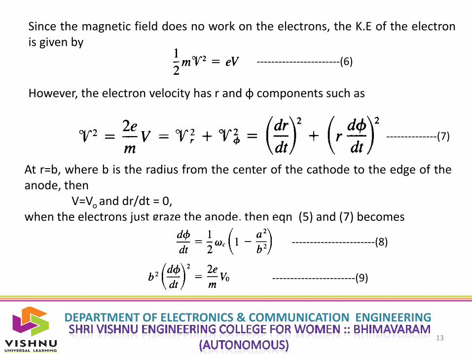
Since the magnetic field does no work on the electrons, the K.E of the electronis given by
-----------------------(6)
However, the electron velocity has r and φ components such as
--------------(7)
At r=b, where b is the radius from the center of the cathode to the edge of theanode, then
V=Vo and dr/dt = 0,when the electrons just graze the anode, then eqn (5) and (7) becomes
-----------------------(8)
-----------------------(9)
DEPARTMENT OF ELECTRONICS & COMMUNICATION ENGINEERING
14
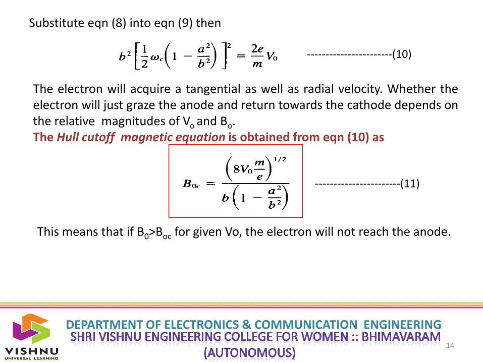
Substitute eqn (8) into eqn (9) then
The electron will acquire a tangential as well as radial velocity. Whether theelectron will just graze the anode and return towards the cathode depends onthe relative magnitudes of Vo and Bo.The Hull cutoff magnetic equation is obtained from eqn (10) as
-----------------------(10)
This means that if B0>Boc for given Vo, the electron will not reach the anode.
-----------------------(11)

DEPARTMENT OF ELECTRONICS & COMMUNICATION ENGINEERING
15
This means that V0 < Voc for a given Bo, the electrons will not reach theanode. The eqn (12) is called Hull cutoff voltage equation.
-----------------------(12)
Cyclotron angular frequency : since the magnetic field is normal to themotion of electrons that travel in the cycloidal path, the outward centrifugalforce is equal to the pulling force. Hence
Where R is the radius of the cycloidal pathv is the tangential velocity of the electron
The Cyclotron angular frequency of the circular motion of the electron is given by
-----------------------(13)
-----------------------(14)

DEPARTMENT OF ELECTRONICS & COMMUNICATION ENGINEERING
16
The period of one complete revolution can be expressed as
Since N no. of reentrant cavities are placed in anode structure, the total phaseshift around the structure is an integral multiple of 2π radiansTherefore, the phase shift between two adjacent cavities ca be expressed as
Where n is an integer indicating the nth mode of oscillations.and m= 0, ±1, ±2, ±3
-----------------------(15)
-----------------------(16)
In order for oscillations to be produced in the structure, the anode dc voltagemust be adjusted so that the average rotational velocity of the electronicscorresponds to the phase velocity of the field in the slow wave structure.Magnetron oscillators are ordinarily operated in π mode.

DEPARTMENT OF ELECTRONICS & COMMUNICATION ENGINEERING
17
Fig Shows the lines of force in π mode of eight-cavity magnetron. It isevident that in the π mode, the excitation is largely in the cavities, havingopposite phase in the successive cavities.
The successive rise and fall ofadjacent anode cavity fieldsmay be regarded as a travellingwave along the surface of theslow-wave structure.For the energy to betransferred from the movingelectrons to the travellingfields , the electrons must bedecelerated by a retarding fieldwhen they pass through theeach anode cavity.
DEPARTMENT OF ELECTRONICS & COMMUNICATION ENGINEERING
18
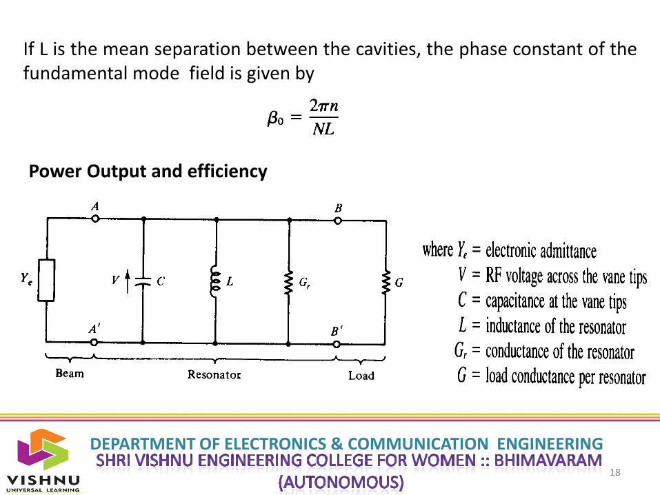
If L is the mean separation between the cavities, the phase constant of thefundamental mode field is given by
Power Output and efficiency
DEPARTMENT OF ELECTRONICS & COMMUNICATION ENGINEERING
19

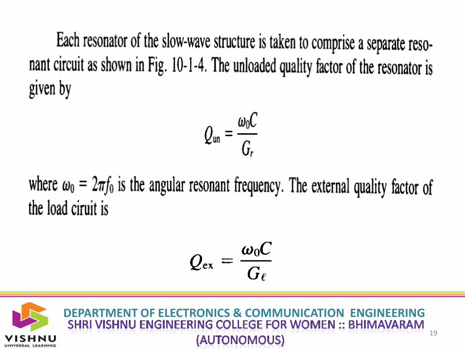
DEPARTMENT OF ELECTRONICS & COMMUNICATION ENGINEERING
20

DEPARTMENT OF ELECTRONICS & COMMUNICATION ENGINEERING
21
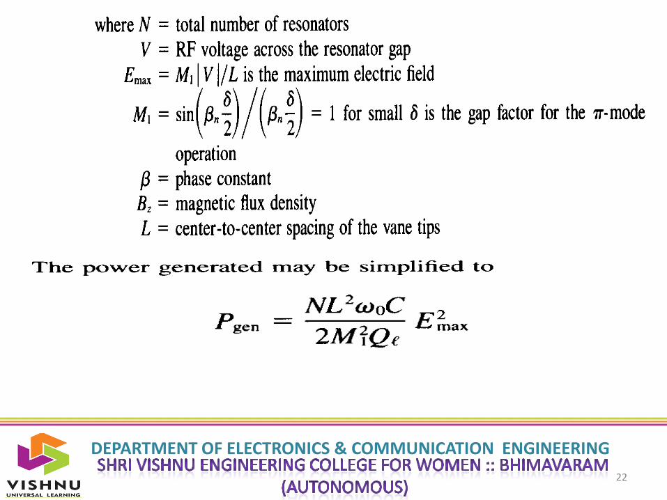
DEPARTMENT OF ELECTRONICS & COMMUNICATION ENGINEERING
22
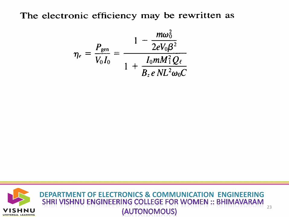
DEPARTMENT OF ELECTRONICS & COMMUNICATION ENGINEERING
23
DEPARTMENT OF ELECTRONICS & COMMUNICATION ENGINEERING
24
THANK YOU
DEPARTMENT OF ELECTRONICS & COMMUNICATION ENGINEERING
MICROWAVE ENGINEERING
Unit 5
1
DEPARTMENT OF ELECTRONICS & COMMUNICATION ENGINEERING
2
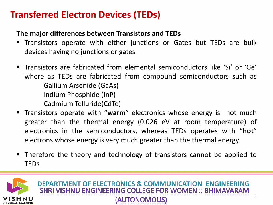
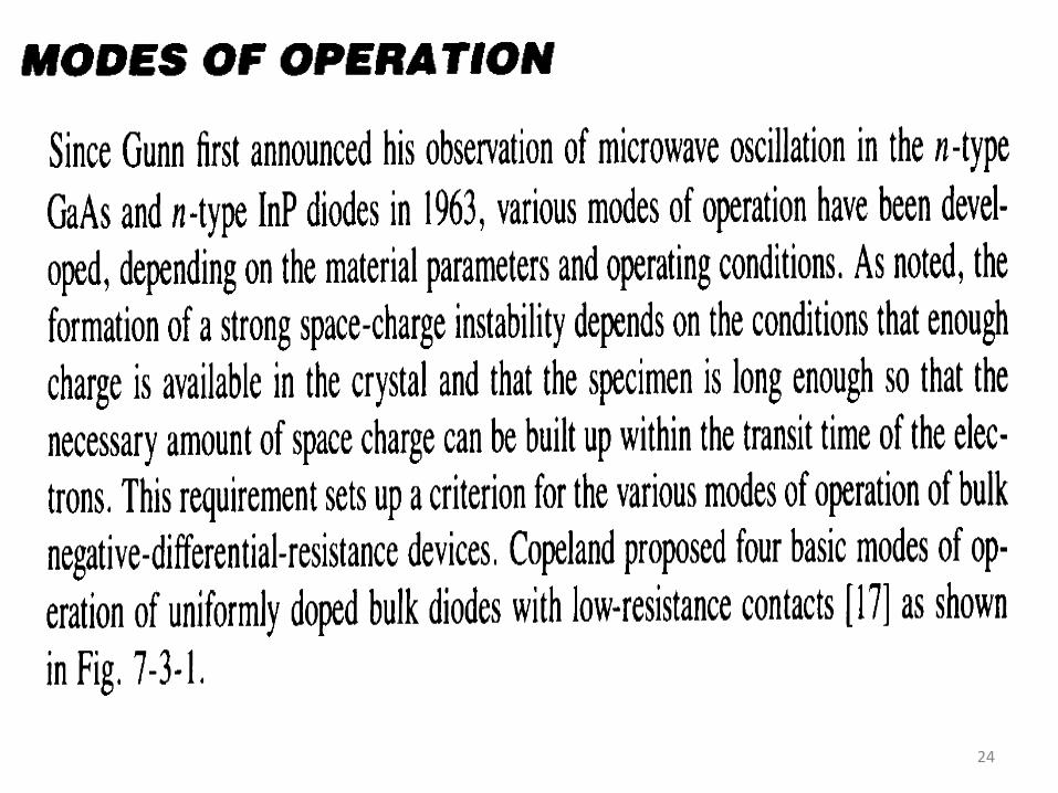
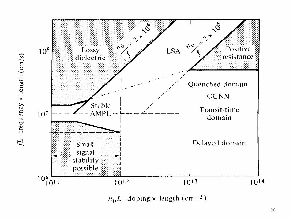
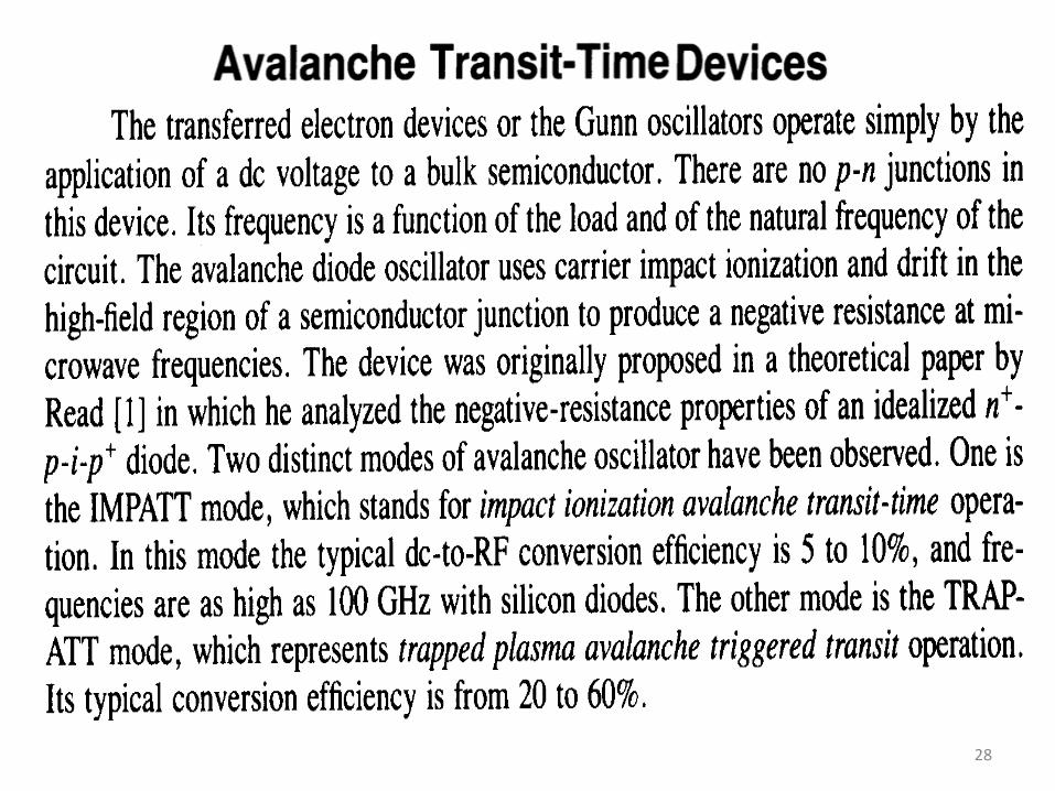
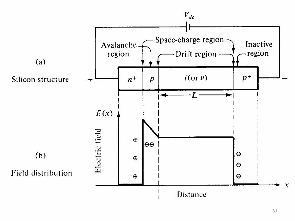
Transferred Electron Devices (TEDs)
The major differences between Transistors and TEDs Transistors operate with either junctions or Gates but TEDs are bulk
devices having no junctions or gates
Transistors are fabricated from elemental semiconductors like ‘Si’ or ‘Ge’where as TEDs are fabricated from compound semiconductors such as
Gallium Arsenide (GaAs)Indium Phosphide (InP)Cadmium Telluride(CdTe)
Transistors operate with “warm” electronics whose energy is not muchgreater than the thermal energy (0.026 eV at room temperature) ofelectronics in the semiconductors, whereas TEDs operates with “hot”electrons whose energy is very much greater than the thermal energy.
Therefore the theory and technology of transistors cannot be applied toTEDs

DEPARTMENT OF ELECTRONICS & COMMUNICATION ENGINEERING
3
Gunn Effect Diodes (GaAs Diodes)
DEPARTMENT OF ELECTRONICS & COMMUNICATION ENGINEERING
4
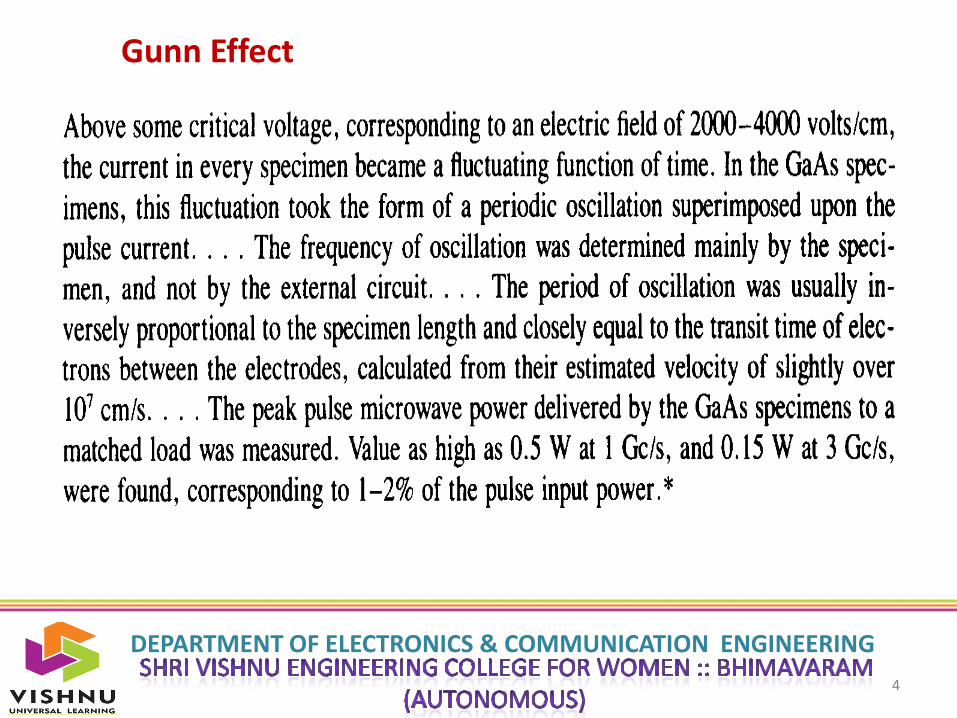
Gunn Effect
DEPARTMENT OF ELECTRONICS & COMMUNICATION ENGINEERING
5
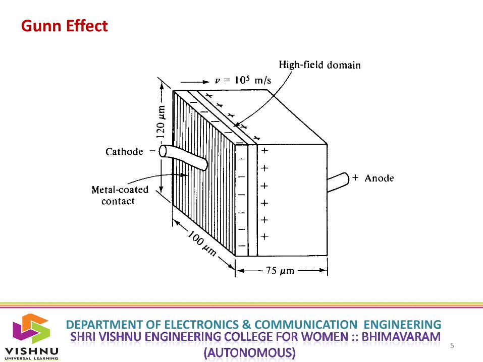
Gunn Effect
DEPARTMENT OF ELECTRONICS & COMMUNICATION ENGINEERING
6
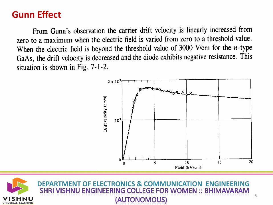
Gunn Effect
DEPARTMENT OF ELECTRONICS & COMMUNICATION ENGINEERING
7
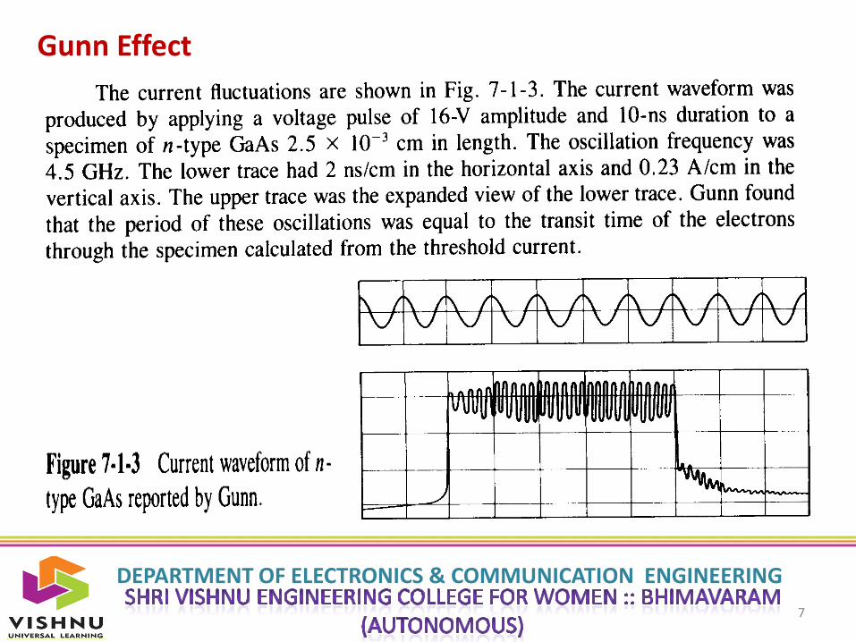
Gunn Effect

DEPARTMENT OF ELECTRONICS & COMMUNICATION ENGINEERING
8
Gunn Effect
DEPARTMENT OF ELECTRONICS & COMMUNICATION ENGINEERING
9
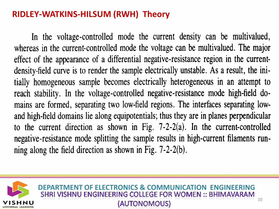
RIDLEY-WATKINS-HILSUM (RWH) Theory
DEPARTMENT OF ELECTRONICS & COMMUNICATION ENGINEERING
10
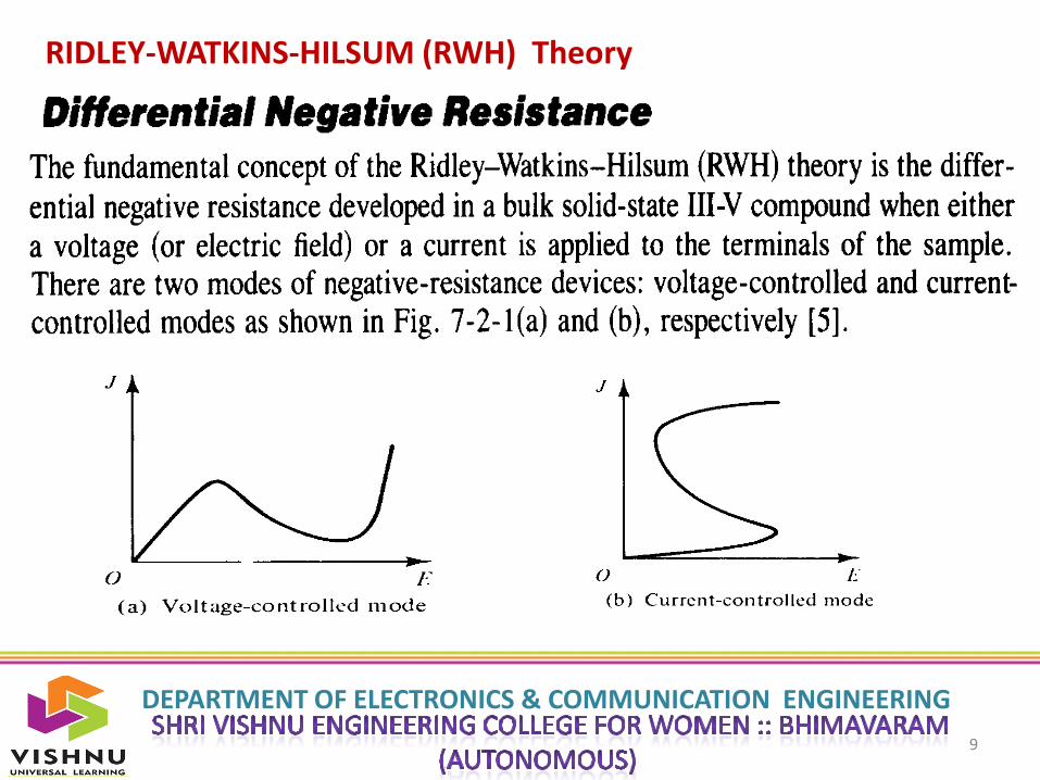
RIDLEY-WATKINS-HILSUM (RWH) Theory

DEPARTMENT OF ELECTRONICS & COMMUNICATION ENGINEERING
11
RIDLEY-WATKINS-HILSUM (RWH) Theory

DEPARTMENT OF ELECTRONICS & COMMUNICATION ENGINEERING
12
RIDLEY-WATKINS-HILSUM (RWH) Theory
DEPARTMENT OF ELECTRONICS & COMMUNICATION ENGINEERING
13
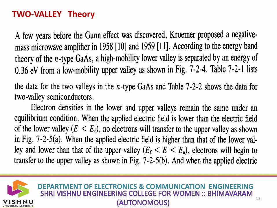
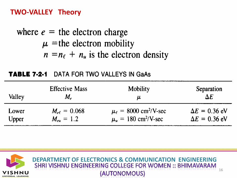
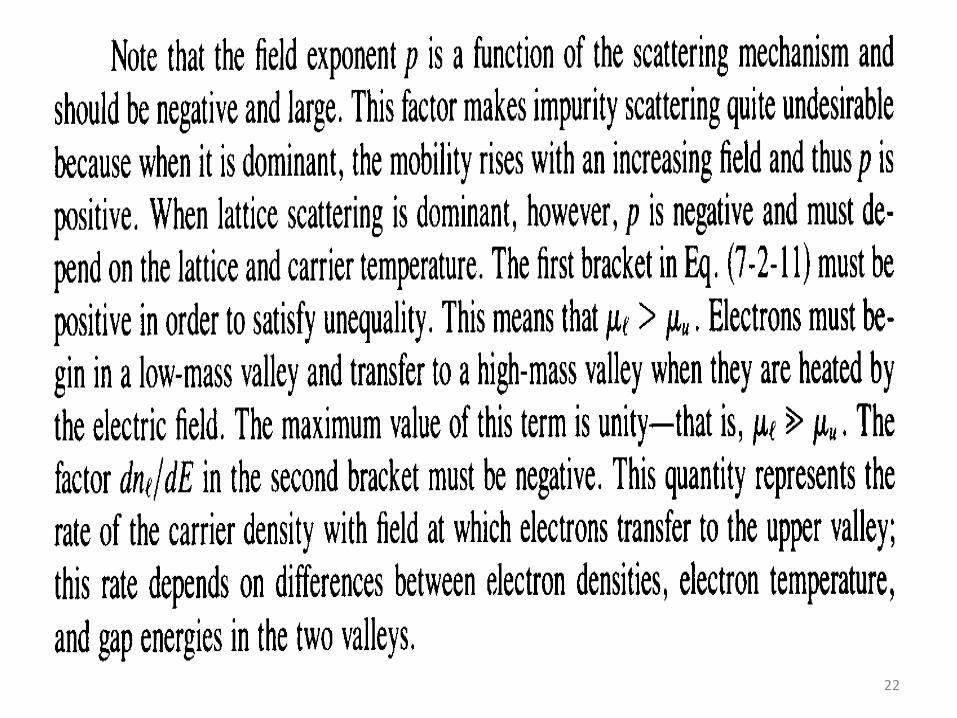
TWO-VALLEY Theory

DEPARTMENT OF ELECTRONICS & COMMUNICATION ENGINEERING
14
TWO-VALLEY Theory

DEPARTMENT OF ELECTRONICS & COMMUNICATION ENGINEERING
15
TWO-VALLEY Theory
DEPARTMENT OF ELECTRONICS & COMMUNICATION ENGINEERING
16
TWO-VALLEY Theory

DEPARTMENT OF ELECTRONICS & COMMUNICATION ENGINEERING
17
TWO-VALLEY Theory

DEPARTMENT OF ELECTRONICS & COMMUNICATION ENGINEERING
18
TWO-VALLEY Theory

DEPARTMENT OF ELECTRONICS & COMMUNICATION ENGINEERING
19
TWO-VALLEY Theory

DEPARTMENT OF ELECTRONICS & COMMUNICATION ENGINEERING
20
TWO-VALLEY Theory

DEPARTMENT OF ELECTRONICS & COMMUNICATION ENGINEERING
21
TWO-VALLEY Theory
22

23
24

25
26

27
28

29

30
31

32
33

34
35

36
37

38
39

40

41

42
Thank You