microwave unit 1
TRANSCRIPT

7/23/2019 Microwave Unit 1
http://slidepdf.com/reader/full/microwave-unit-1 1/141
1
Microwave &
Antenna (EL-354)
M.S. ALAM
Associate Professor
Department of Electronics Engineering
A.M.U. Al igarh
E- mail: [email protected]
Starting: 4
th
August 201 4

7/23/2019 Microwave Unit 1
http://slidepdf.com/reader/full/microwave-unit-1 2/141
2
..ABOUT YOUR
TEACHER
..
1988: Bachelor of Engineering (Electronics & Communication Engineering)
1991 : Master of Engineering (Electronics
& Communication Engineering)
2002:
Doctorate degree (Ph. D)
(Electronics Engineering)
2010:
Post doctorate ( Nano- electronics
)
Visit website for more deta ils:
http://www.amu.ac.in/dshowfacultydata. jsp?did=32&eid=3208

7/23/2019 Microwave Unit 1
http://slidepdf.com/reader/full/microwave-unit-1 3/141
Course
Structure

7/23/2019 Microwave Unit 1
http://slidepdf.com/reader/full/microwave-unit-1 4/141
Course deals with..
+
µ
Waves fascinated human being due their
widespread use;
Antenna helps to broadcast signal waves
carrying messages and subsequently their
retrieval
µ
Waves Antenna

7/23/2019 Microwave Unit 1
http://slidepdf.com/reader/full/microwave-unit-1 5/141

7/23/2019 Microwave Unit 1
http://slidepdf.com/reader/full/microwave-unit-1 6/141
Dish TV
Music, news etc. are received through use of
µ
waves
ProgramGeneration
ProgramUpload
Satellite
DishAntenna
Receiver

7/23/2019 Microwave Unit 1
http://slidepdf.com/reader/full/microwave-unit-1 7/141
RADAR
(radio detection and ranging)
Aircraft guidance, collision avoidance etc
Space Exploration
Monitoring of incoming microwave signals
from outer space or from other galaxies etc.
Medical Application
Selective heating of body organs, imaging ……
µ waves use are spreading in other numerous areas…

7/23/2019 Microwave Unit 1
http://slidepdf.com/reader/full/microwave-unit-1 8/141
Less Crowded
Frequency
Spectrum
µwaves
2
4
3
1 igher
Bandwidth
Higher Speed
of Operation
Lower
Interference
Possible reasons

7/23/2019 Microwave Unit 1
http://slidepdf.com/reader/full/microwave-unit-1 9/141
Objectives.
Familiarize the students about
importance of µwaves (1 - 300GHz)
How µwaves devices and circuits
work? and their applications
Obviously, various aspects of
µwaves will not be covered

7/23/2019 Microwave Unit 1
http://slidepdf.com/reader/full/microwave-unit-1 10/141
Assessment
Course work will includes:
reporting to the class in time;
taking note of important points discussed in the class;
how well you respond when enquired about the subject;
home assignment etc.
Final
Semester
Exam, 60%
MidSemester
xam, 25%
CourseWork, 15%
Motive
Students take
interest in day
- to- day class
activities and
keep their notes
updated. .

7/23/2019 Microwave Unit 1
http://slidepdf.com/reader/full/microwave-unit-1 11/141
Books
S. Y. Lio, “Microwave Devices & Circuits”
Prentice Hall of India, 2003 (Text book)
G. Kennedy and B. Davis,
“Electronic Communication Systems”, TMH,
1985
M. L. Sisodia & V. L Gupta, “Microwaves”,
New Age International Publishers, N. Delhi,
2001
J. D. Kraus, R. J. Marhefka & A. S. Khan,
“Antennas and Wave Propagation, ” 4th ed. ,
Tata McGraw- Hill, New Delhi, 201 0.

7/23/2019 Microwave Unit 1
http://slidepdf.com/reader/full/microwave-unit-1 12/141
Books
C. G. Christodolou, P. F. Wahid,
“Fundamentals of Antennas: Concepts and
Applications” , PHI, N. Delhi, 2004.
M. M. Radmanesh, “Radio Frequency and
Microwave Electronics Illustrated”, Pearson
Education- 2001 .
Website address to access study materia ls:
http://www.amu.ac.in/showstudym.jsp?did=32&eid=3208

7/23/2019 Microwave Unit 1
http://slidepdf.com/reader/full/microwave-unit-1 13/141
Study Plan
µwaves
components and their
working ----- Unit-I
Howhigh power µwaves
signals
generated & amplified ----- Unit II
How low power µwaves signals
generated & amplified -----Unit-III
Various types of antennas and their
applications ------Unit-IV
Focus
How µwaves devices
and c ircuits work?

7/23/2019 Microwave Unit 1
http://slidepdf.com/reader/full/microwave-unit-1 14/141
µ
Wave
devices/circuits
Fr eq uen cy is h ig h
1GHz
Various parasitics (undesired circuit
elements) automatically cropped up
How to differentiate?
f< 1 GHz
f
p
ALL
pass
filter
f
p
f> 1 GHz
Band
pass
filter
Parasitics
Parasitics
7/23/2019 Microwave Unit 1
http://slidepdf.com/reader/full/microwave-unit-1 15/141
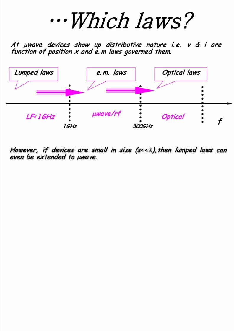
…Which laws?
However, if devices are small in size (s< < λ), then lumped laws can
even be extended to µwave.
LF< 1 GHz
µwave/rf
Optical
f
Lumped laws e. m. laws Optical laws
1 GHz 300GHz
At µwave devices show up distributive nature i. e. v & i are
function of position x and e. m laws governed them.

7/23/2019 Microwave Unit 1
http://slidepdf.com/reader/full/microwave-unit-1 16/141
dt
dH E µ
∫
⇒ KVL0 dl . EV 0 E
0 or0 If
1v
→
∞
ε
µε
Lumped laws can even be extended for
µ
wave elements provided their
sizes are small.
Insight…
j dt dE H +
ε
KCL0 .j H . ⇒
0 or0 If
1v
→
∞
ε
µε
Distributive,
where elements
are not loc alized
Lumped,
where
elements
have
been
localized
Ex:

7/23/2019 Microwave Unit 1
http://slidepdf.com/reader/full/microwave-unit-1 17/141
HF Parameters
Y or Z or H–parameters are used for analysis for
LF<1GHz devices and circuits
net v (or net i) and SC (or OC) are used for their
description
Background
Ref: Mathew M. Radmanesh Book, pp. 287- 302 ; L io Book , pp. 1 41- 1 43
At
µ
waves, v and i become function of x and their
wave descriptions are required
…. Conventional Y/Z/H FAILS, because……

7/23/2019 Microwave Unit 1
http://slidepdf.com/reader/full/microwave-unit-1 18/141
Reason being..
Non- availability of equipment to measure position
variable v or i
Short (SC) or open (OC) circuits are not possible to
carry out
Active devices become unstable when short
circuited

7/23/2019 Microwave Unit 1
http://slidepdf.com/reader/full/microwave-unit-1 19/141
Why?
sc
V=0 ; I#0
OC
I=0 ; V#0
Y or
Z or H
can‘t be
applied

7/23/2019 Microwave Unit 1
http://slidepdf.com/reader/full/microwave-unit-1 20/141
Alternate Solution
A proper tool to give port description for these
devices without actua lly harming the device
Use scattering (S) parameters for µwave
(> 1 GHz) devices

7/23/2019 Microwave Unit 1
http://slidepdf.com/reader/full/microwave-unit-1 21/141
S-parameters
Easy to measure at
µ
wave frequencies
Based on transmitted and reflected
wave
Neither SC nor OC is required
SC could even harm the
µ
wave device
Similar kind of defining equation as
used for Y or Z or H
S-parameters in context with 2-port
7/23/2019 Microwave Unit 1
http://slidepdf.com/reader/full/microwave-unit-1 22/141
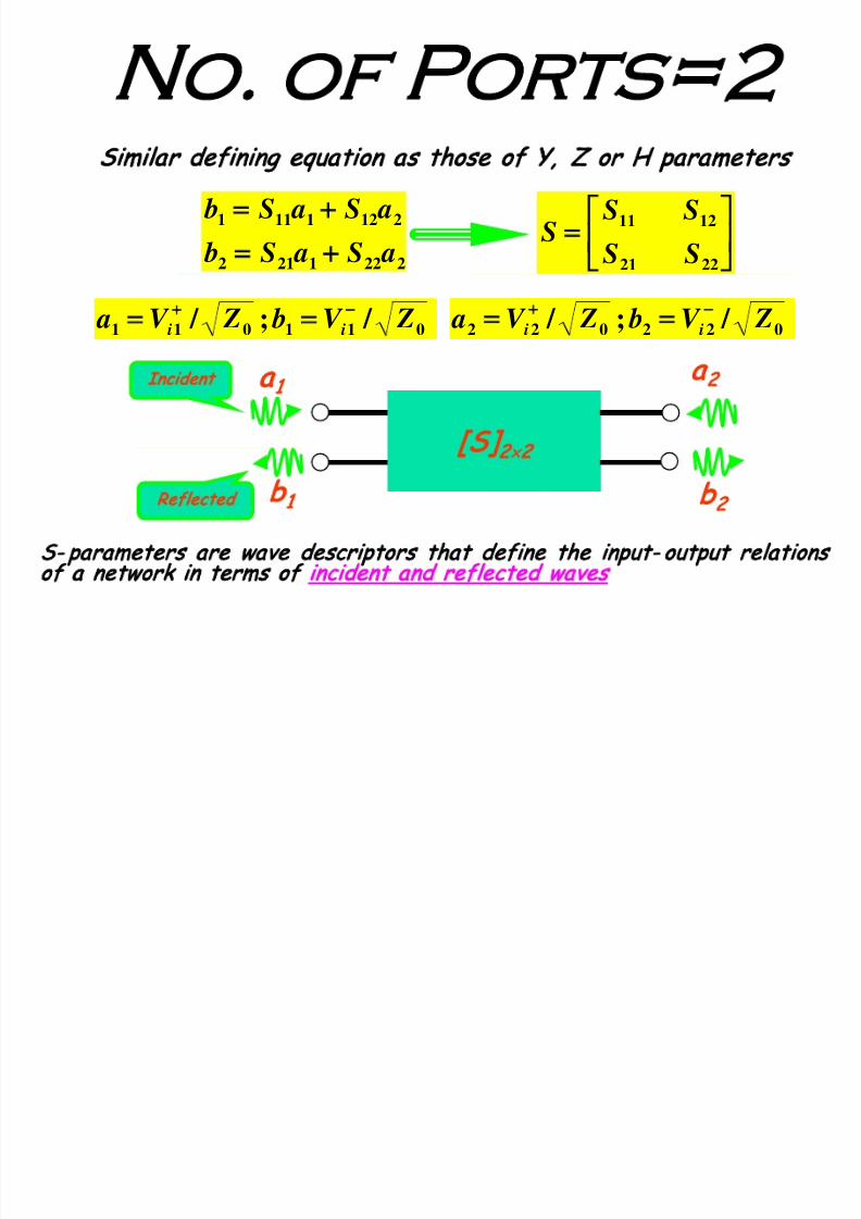
S- parameters are wave descriptors that define the input- output relations
of a network in terms of incident and reflected waves
No. of Ports=2
2221212
2121111
aS aS b
aS aS b
+
+
=
22 21
12 11
SS
SSS
Similar defining equation as those of Y, Z or H parameters
/ ; / 022022 ZV b ZV a ii−
=
/ ; / 011011 ZV b ZV a ii−
=
[S]
2
×
2
a
1
b
1
a
2
b
2
Incident
Reflected

7/23/2019 Microwave Unit 1
http://slidepdf.com/reader/full/microwave-unit-1 23/141
S
1 1
& S
21
Matched load Z0 is fully
absorptive i. e. all wave is
taken by load and nothing
is given out i. e. a
2
= 0
S
mn
response
Excitation
S 11 = Reflected
Incident =
b 1
a 1 a 2 = 0
S 21 = Transmitted
Incident =
b2
a 1 a 2 = 0
Input
reflection
Forward
transmission
Incident TransmittedS 21
S 11
Reflectedb 1
a 1
b 2
Matched
load Z0a 2 = 0
DUT
S21
S11
Gen
Forward
Z0
ZOUT
ZOUT=Z0

7/23/2019 Microwave Unit 1
http://slidepdf.com/reader/full/microwave-unit-1 24/141
S
22
& S
1 2
S
mn
response
Excitation
IncidentTransmitted S 12
S 22
Reflected
b2
a 2
a 1 = 0
Z 0
Load
DUT
S12
S22
Gen
Reverse
S 22 = Reflected
Incident =
b 2
a 2 a 1 = 0
S 12 = Transmitted
Incident =
b1
a 2 a 1 = 0
Output reflection
coefficient
Reverse
transmission
Z0
ZIN
Matched load Z0 is fully
absorptive i. e. all wave is
taken by load and nothing
is given out i. e. a
1
= 0
Z0=ZIN
7/23/2019 Microwave Unit 1
http://slidepdf.com/reader/full/microwave-unit-1 25/141
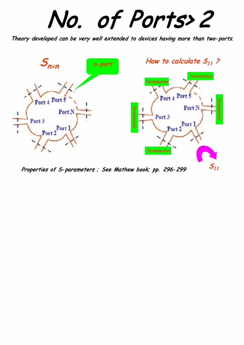
No. of Ports> 2
How to calculate S
1 1
?
S
n×n
n- port
Theory developed ca n be very well extended to devices ha ving more tha n two- ports
.
Termination
Termination
Termination
m
n
o
m
n
o
S
1 1
Properties of S- para meters ; See Mathew book; pp. 296- 299
7/23/2019 Microwave Unit 1
http://slidepdf.com/reader/full/microwave-unit-1 26/141
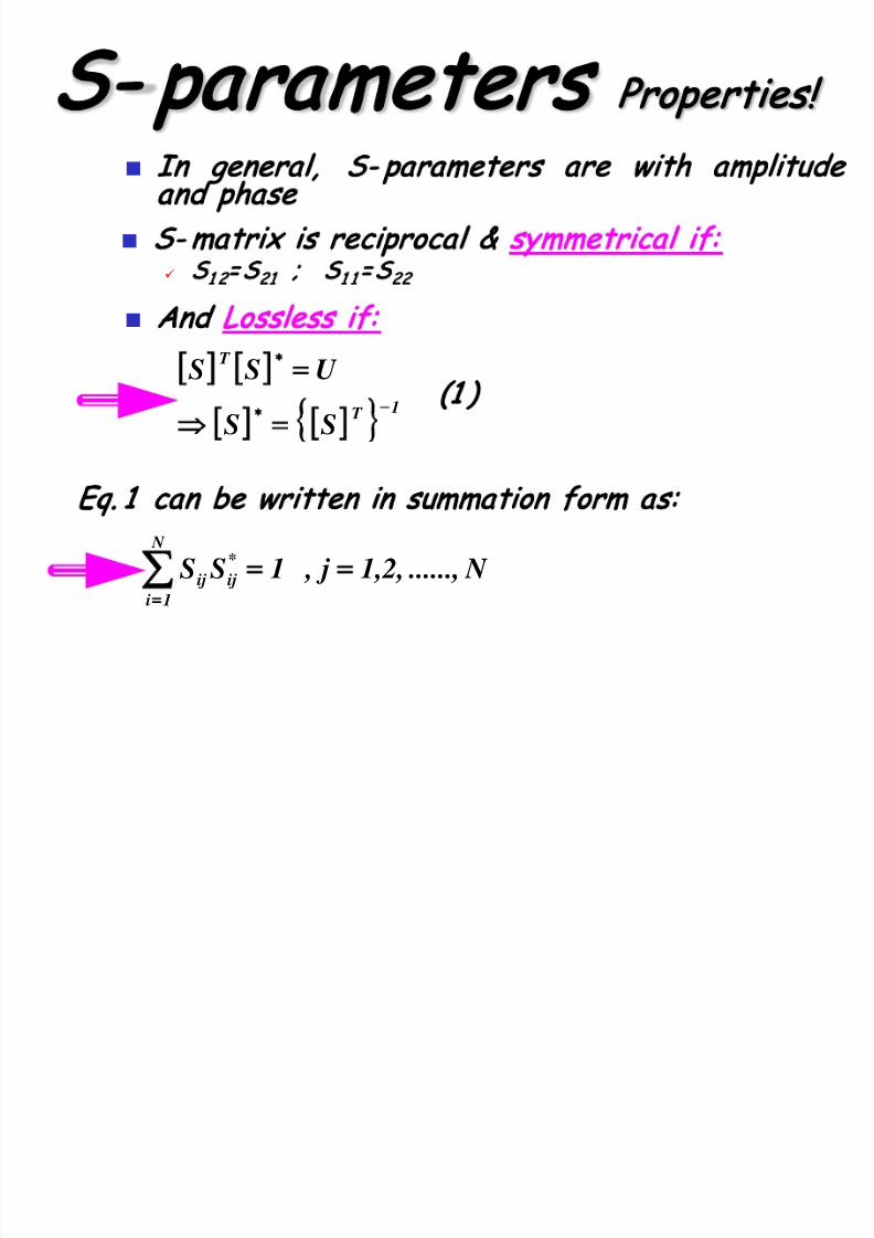
S- parameters Properties
In general, S- parameters are with amplitude
and phase
Eq. 1 can be written in summation form as:
N ......,1,2, j , 1SS *
ij
N
1i
ij =
=
[ ] [ ]
[ ] [ ]
1T
T
SS
U SS
−
=
=
(1 )
And Lossless if:
S- matrix is reciproca l & symmetrical if:
S
1 2
= S
21
; S
1 1
= S
22

7/23/2019 Microwave Unit 1
http://slidepdf.com/reader/full/microwave-unit-1 27/141
Cont..
Unity Property The sum of products of any column of [S] with the
conjugate of that column gives UNITY.
The sum of products of any row of [S] with the
conjugate of that row gives UNITY.
1SSSS * 21 21*1111 =
1SSSS *
22 22
*
1212 =
=
22 21
12 11
SSSSS
j all i forSS kj
N
k
ki ≠
=
,0*
1
Zero property:
The sum of products of any column of [S] with the
conjugate of a different column gives ‘ZERO’.
The sum of products of any row of [S] with the
conjugate of a different row gives ‘ZERO’.
7/23/2019 Microwave Unit 1
http://slidepdf.com/reader/full/microwave-unit-1 28/141
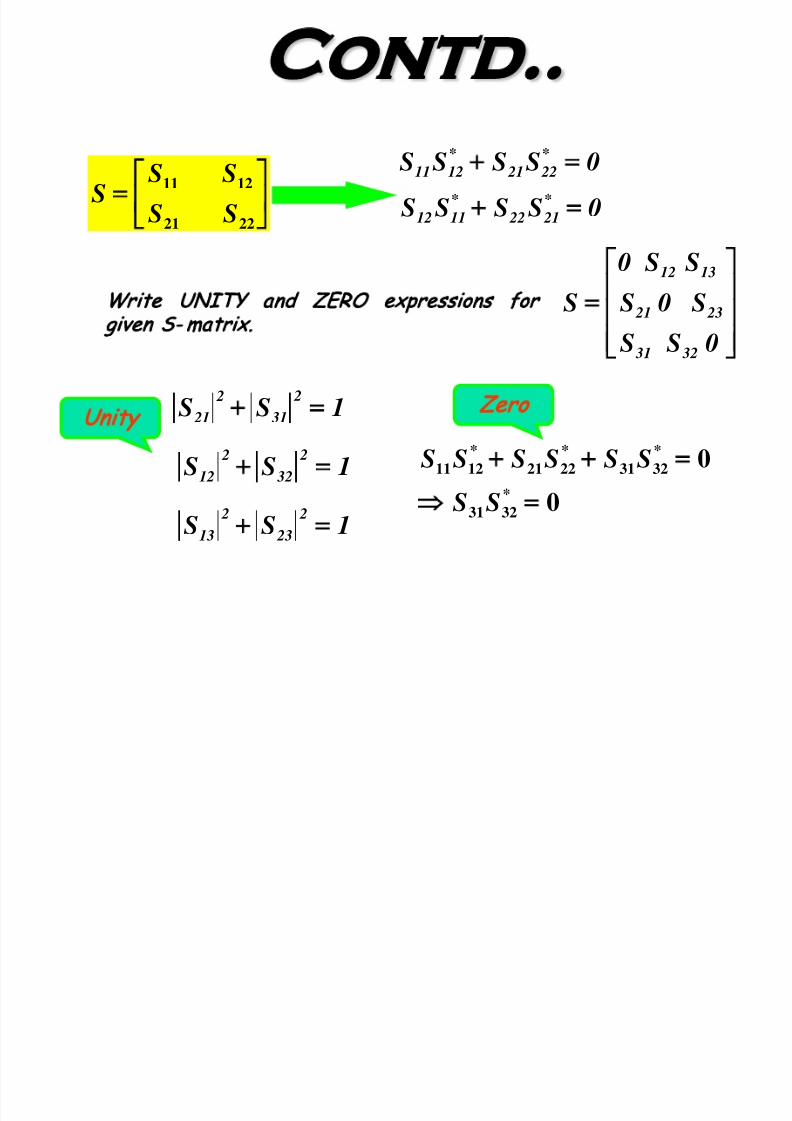
Contd..
0SSSS *
22 21
*
1211 =
0SSSS *
21 22
*
1112 =
=
22 21
12 11
SS
SSS
=
0S S
S 0S
SS 0
S
32 31
23 21
1312
Write UNITY and ZERO expressions for
given S- matrix .
1SS 2
32
2
12 =
1SS 2
23
2
13 =
1SS
2
31
2
21 =
Unity
0
0
*
3231
*
3231
*
2221
*
1211
=
=
SS
SSSSSS
Zero
7/23/2019 Microwave Unit 1
http://slidepdf.com/reader/full/microwave-unit-1 29/141
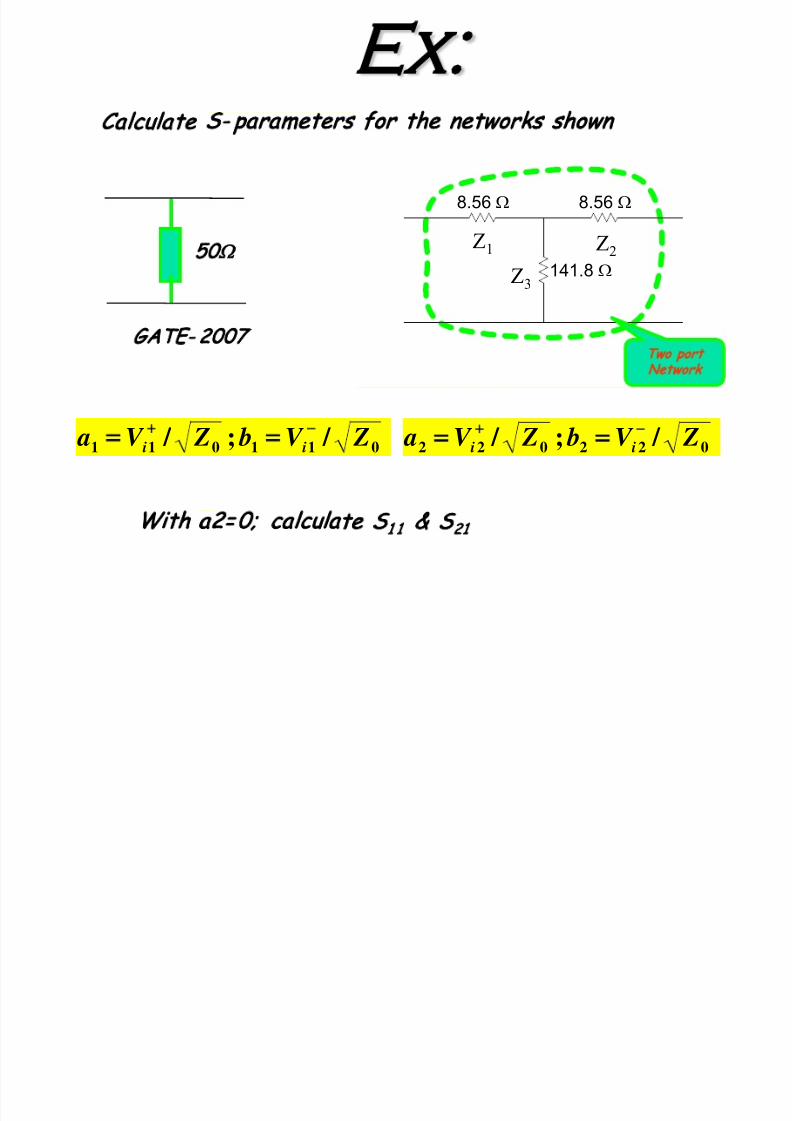
Ex:
8.56 Ω 8.56 Ω
141.8 Ω
Two port
Network
Z1 Z
2
Z3
Calculate S- parameters for the networks shown
50
Ω
GATE- 2007
With a2=0; calculate S
1 1
& S
21
/ ; / 022022 ZV b ZV a ii
−
= / ; / 011011 ZV b ZV a ii
−
=
7/23/2019 Microwave Unit 1
http://slidepdf.com/reader/full/microwave-unit-1 30/141
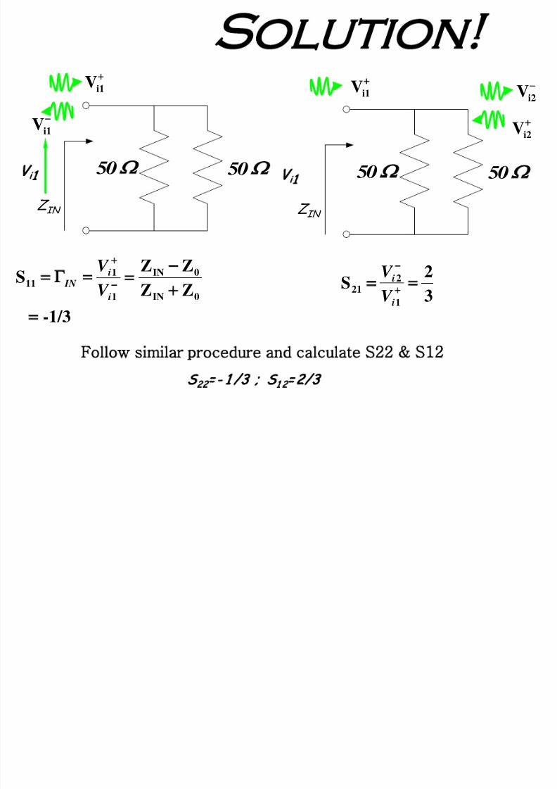
Solution
S
22
= - 1 /3 ; S
1 2
=2/3
Follow similar procedure and calculate S22 S12
i1V
50 50
Z IN
V
i
1
−
i1V
-1/3 ZZ
ZZS
0IN
0IN
1
1
11
=
=
i
i IN
V
V
−
i2V
50 50
Z IN
V
i
1
i1V
i2V
3
2S
1
2
21 =
i
i
V
V

7/23/2019 Microwave Unit 1
http://slidepdf.com/reader/full/microwave-unit-1 31/141
Solution
S
22
=0 ; S
1 2
=0 .71
Follow similar procedure
0
0
11 Z Z
Z ZS
IN
IN
=
Ω
+
50) //( 23
1
o
IN
Z Z Z
Z Z
0.011 =S
8.56 Ω 8.56 Ω
141.8 Ω Ω50
Two port
Network
Z1 Z
2
Z3
Z
IN
−i2Vi1V
i2V
3
2S
1
2
21 =
i
i
V
V
T ry fe w mor e e xe rc ises g iv en in Mathew Book

7/23/2019 Microwave Unit 1
http://slidepdf.com/reader/full/microwave-unit-1 32/141
Alternative
Determine A, B, C, and D matrix for given network
+
−
+
D Z
C)ADZ
D
1
0
2
0
0
2
0
0
2
0
S
Use the conversion formula and determine S- parameters.
Network V1
V2
I1
I2
02
1
2=
=
I V
V A
02
1
2=
=
I V
I C
02
1
2=−
=
V I
I D
02
1
2=−
=
V I
V B
7/23/2019 Microwave Unit 1
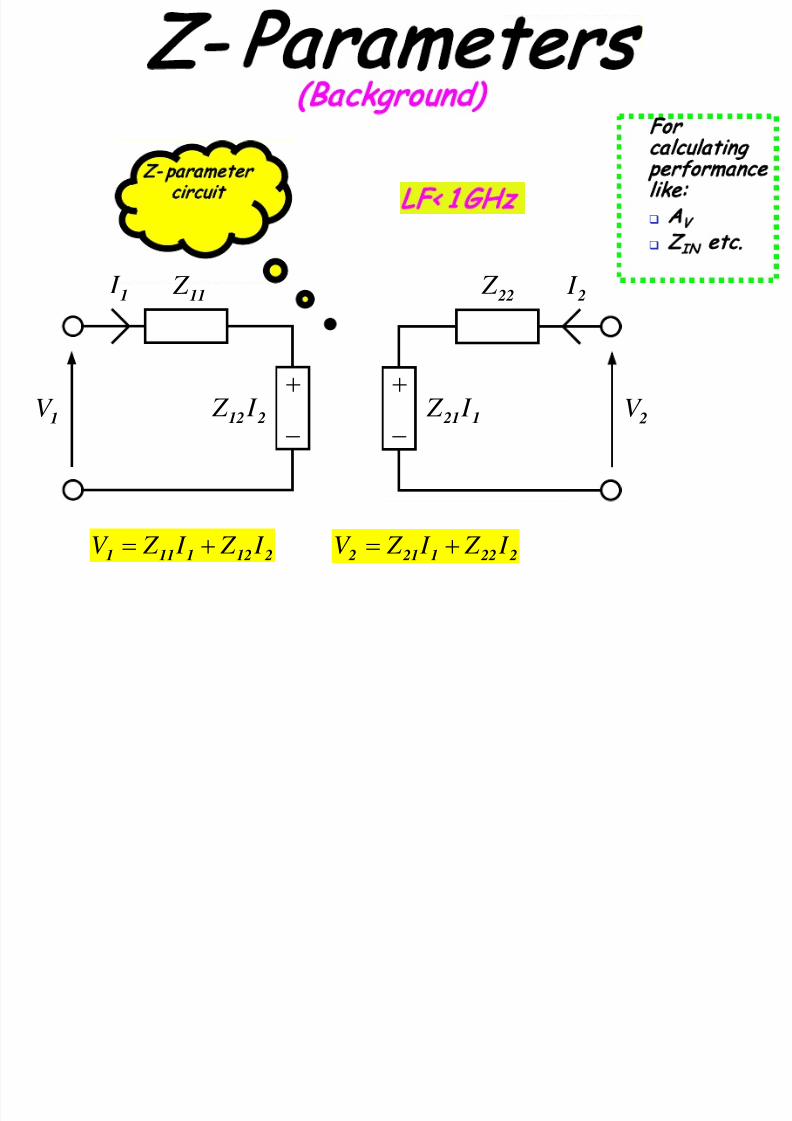
http://slidepdf.com/reader/full/microwave-unit-1 33/141
1V
1 I
2V
2 I 11 Z
212 I Z
+
−1 21 I Z
+
22 Z
−
2121111 I Z I Z V
+= 2 221 21 2 I Z I Z V
+=
Z- Parameters
(Background)
Z- parameter
circuit
LF< 1 GHz
For
calculating
performance
like:
A
V
Z
IN
etc.
7/23/2019 Microwave Unit 1
http://slidepdf.com/reader/full/microwave-unit-1 34/141
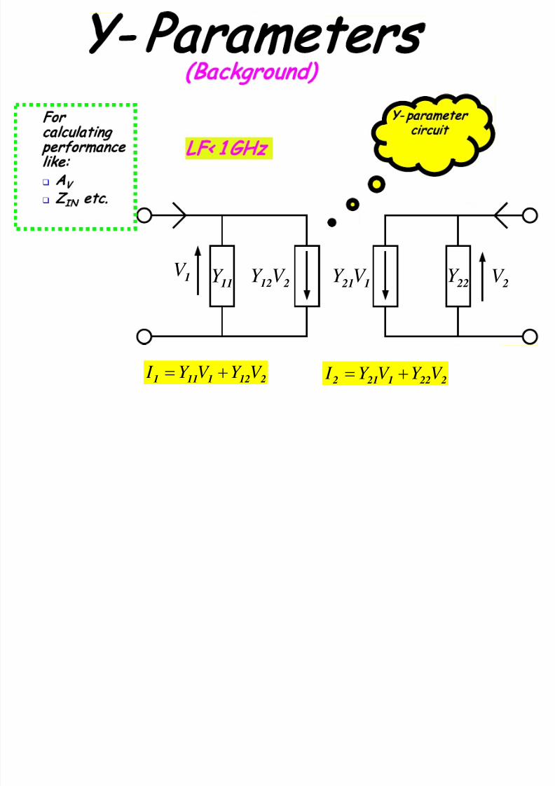
1V 11Y 212V Y 1 21V Y 22Y 2V
2121111 V Y V Y I += 2 221 21 2 V Y V Y I +=
Y- parameter
circuit
LF< 1 GHz
For
calculating
performance
like:
A
V
Z
IN
etc.
Y- Parameters
(Background)

7/23/2019 Microwave Unit 1
http://slidepdf.com/reader/full/microwave-unit-1 35/141
Question?
How the performances like A
V
, Z
IN
etc.
can be calculated for µwave
devices/circuits?
Convert S to circuit defin ing parameters like Z/Y/H S
Y
H
Z
Answer
7/23/2019 Microwave Unit 1
http://slidepdf.com/reader/full/microwave-unit-1 36/141
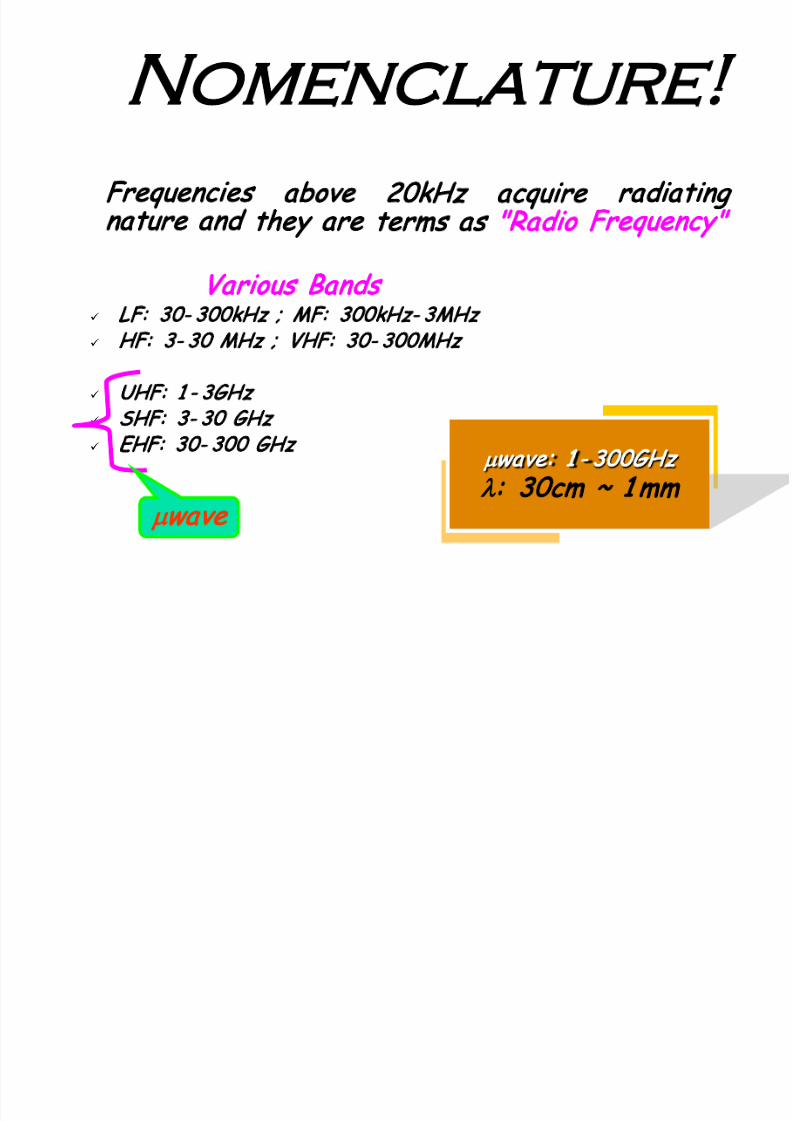
Nomenclature
Frequencies above 20kHz acquire radiating
nature and they are terms as "Radio Frequency"
Various Bands
LF: 30- 300kHz ; MF: 300kHz- 3MHz
HF: 3- 30 MHz ; VHF: 30- 300MHz
UHF: 1 - 3GHz
SHF: 3- 30 GHz
EHF: 30- 300 GHz
µwave: 1 - 300GHz
λ: 30cm ~ 1mm
µwave

7/23/2019 Microwave Unit 1
http://slidepdf.com/reader/full/microwave-unit-1 37/141
Unit-I:
µ
Wave
Components and Measurements
Guided Wave Propagation
Wave guide Components
Wave guide tuning, matching and loading
Directional coupler, Isolator, Circulator and Detector
Modeling of microwave components: S-parameters-----Finished
Measurements of microwave quantities
µ
waves
components and their working
Topics
Purpose
7/23/2019 Microwave Unit 1
http://slidepdf.com/reader/full/microwave-unit-1 38/141
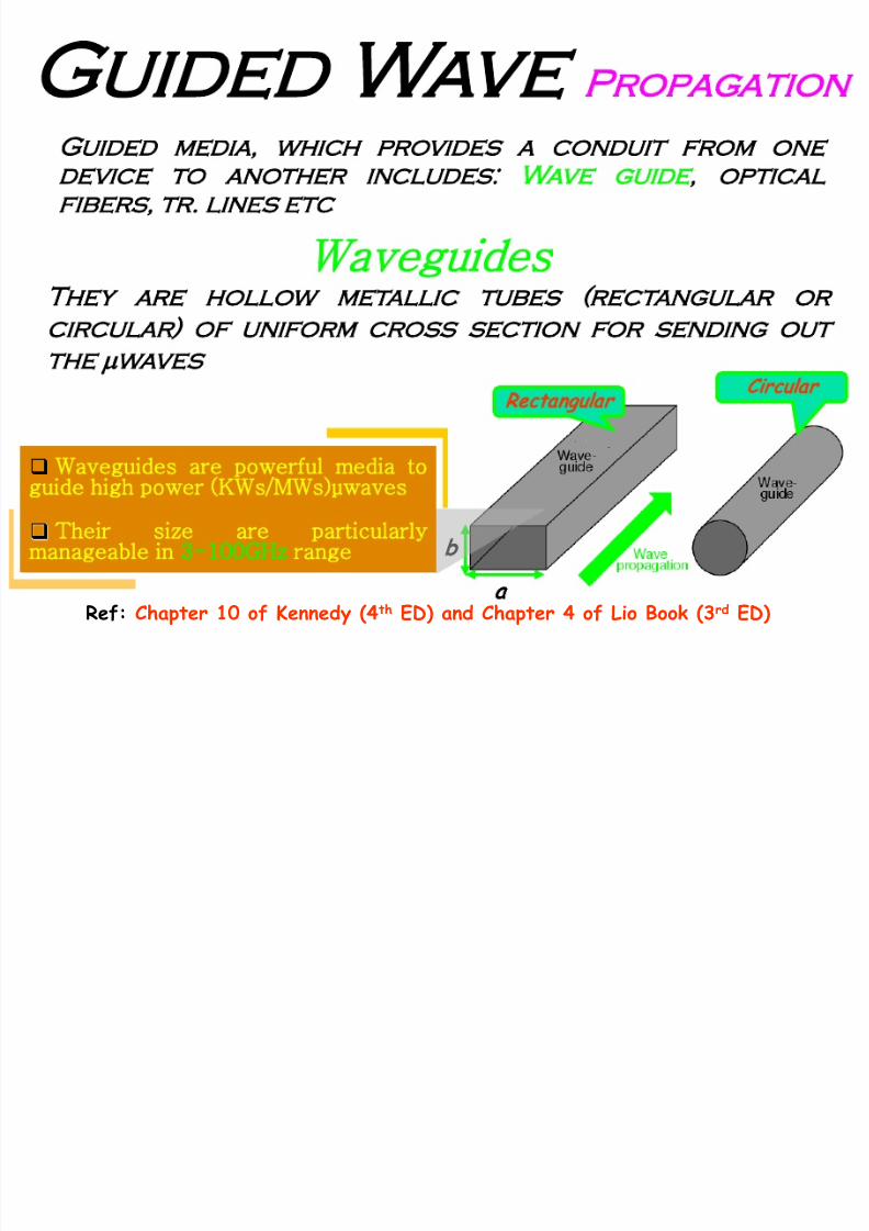
Guided Wave Propagation
Guided media, which provides a conduit from one
device to another includes: Wave guide, optical
fibers, tr. lines etc
They are hollow metallic tubes (rectangular or
circular) of uniform cross section for sending out
the
µ
waves
Waveguides
Rectangular
Circular
a
b
Waveguides are powerful media to
guide high power (KWs/MWs)µwaves
Their size are particularly
manageable in 3-100GHz range
Ref: Chapter 10 of Kennedy (4th ED) and Chapter 4 of Lio Book (3rd ED)

7/23/2019 Microwave Unit 1
http://slidepdf.com/reader/full/microwave-unit-1 39/141
µwaves Propagation
Angle of incidence(A) Angle of reflection (B)
(A = B)f
µwaves propagate through successive reflections from the inner
walls of the guide
There are two modes of propagation: TE & TM
They are designated as TEmn or TMmn
Where m= no. of half- wave along x; n= no. of half- wave along y
TM: H is
⊥
to direction of propagationE: E is
⊥
to direction of propagation

7/23/2019 Microwave Unit 1
http://slidepdf.com/reader/full/microwave-unit-1 40/141
7/23/2019 Microwave Unit 1
http://slidepdf.com/reader/full/microwave-unit-1 41/141
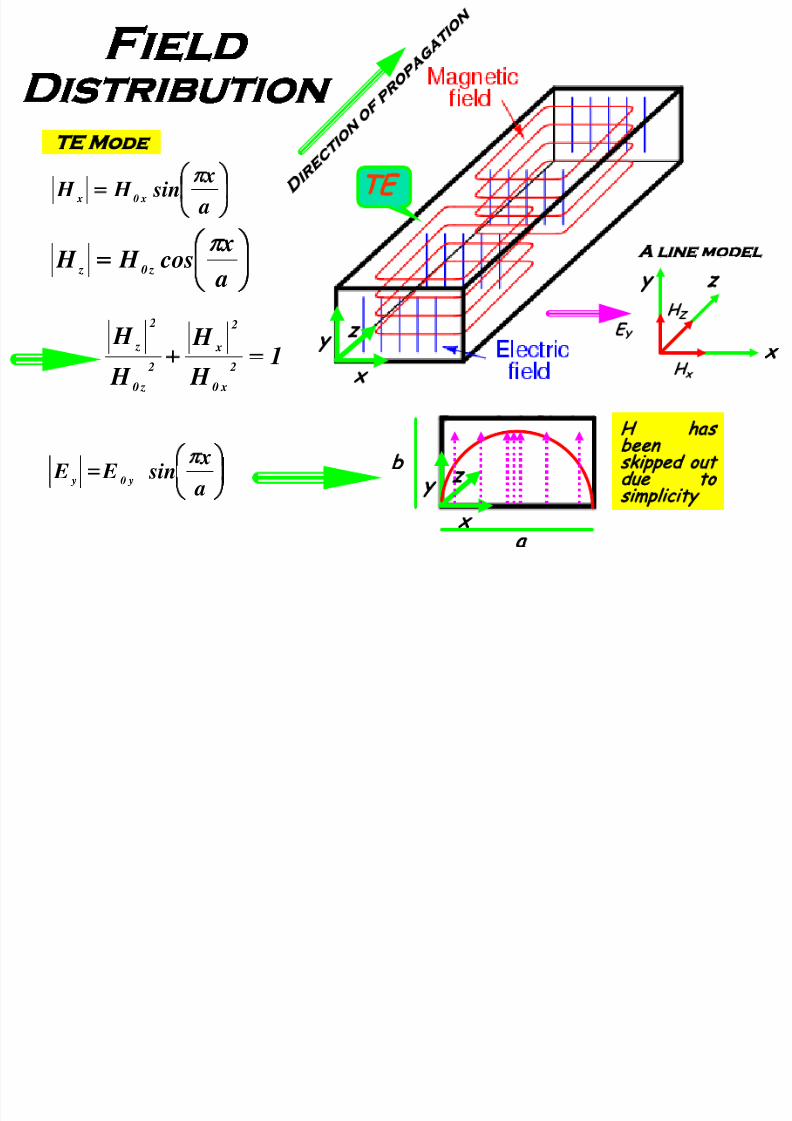
Field
Distribution
=
a
x sin E E
y0 y
π
=
a
x cos H H
z0 z
π
=
a
x sin H H
x0 x
π
x
y
z
TE
1 H
H
H
H 2
x0
2
x
2
z0
2
z=
x
y z
E
Y
H
x
H
Z
A line model
x
y
z
a
b
H has
been
skipped out
due to
simplicity
TE Mode
7/23/2019 Microwave Unit 1
http://slidepdf.com/reader/full/microwave-unit-1 42/141
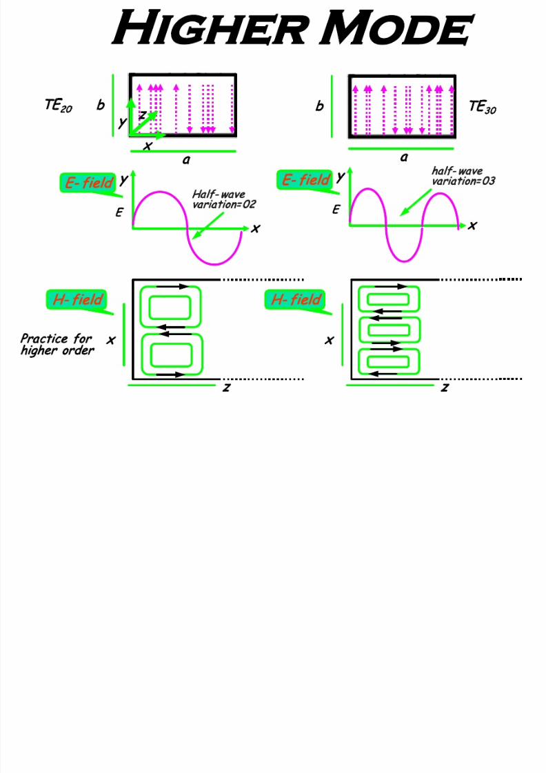
Higher Mode
TE
30
a
x
y
z
E
20
a
b
Practice for
higher order
x
y
E
E- field
Half- wave
variation=02
x
y
E
E- field
half- wave
variation=03
H- field
x
z
H- field
x
z
7/23/2019 Microwave Unit 1
http://slidepdf.com/reader/full/microwave-unit-1 43/141
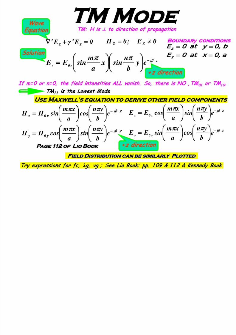
TM Mode
Use M axwell’s equation to derive other field components
0 E E Z
2
Z
2
=
γ 0 E ;0 H Z Z ≠
Wave
Equation
TM: H is
⊥
to direction of propagation
z j
z0 z e y
b
n sin x
a
m sin E E −
=
Solution
+z direction
z
z
β
β
π
π
j
y0 y
j
x0 x
e b
y n sin
a
x m cos H H
e b
y n cos
a
x m sin H H
−
−
=
=
+z direction
a t x
b t y
z
z
=
=
Boundar
y
conditions
z
z
β
β
π
π
j
y0 y
j
x0 x
e b
y n cos
a
x m sin E E
e b
y n sin
a
x m cos E E
−
−
=
=
Page 112 of Lio Book
Field Distribution can be similarly Plot ted
If m= 0 or n= 0, the field intensities ALL vanish. So, there is NO , TM
01
or TM
1 0
.
TM
1 1
is the Lowest Mode
Try expressions for fc,
λ
g, vg ; See Lio Book; pp. 1 09 & 1 1 2 & Kennedy Book

7/23/2019 Microwave Unit 1
http://slidepdf.com/reader/full/microwave-unit-1 44/141
GATE 2 7
H- field
x
z
x
y
z
E
20
a
b
x
y
E
E- field
No. of h alf-wave
variation=02
E- field in rectangular guide of dimension a
×
b is
given as:
z j
y e a
x K E ' 2
sin β
−
=
z
0 cossin β j
y y e b
y n
a
x m E E −
=
Compare the given expression with standard
expression
Ans: TE
20
mode
Determine the mode of propagation in the guide
Try questions: 4. 1 , 4. 4, 4. 5, 4. 1 2; See Lio Book;
pp. 1 61 - 1 62

7/23/2019 Microwave Unit 1
http://slidepdf.com/reader/full/microwave-unit-1 45/141
Waveguide Components
Regulate Flow Of Power in
µ
wave System
Types
Hybrid Tee (Magic Tee)
Hybrid Rings (Rat- Race)
Corners, bends and twists- plane & H- plane Tees
Directional Couplers
Circulators and Isolators

7/23/2019 Microwave Unit 1
http://slidepdf.com/reader/full/microwave-unit-1 46/141
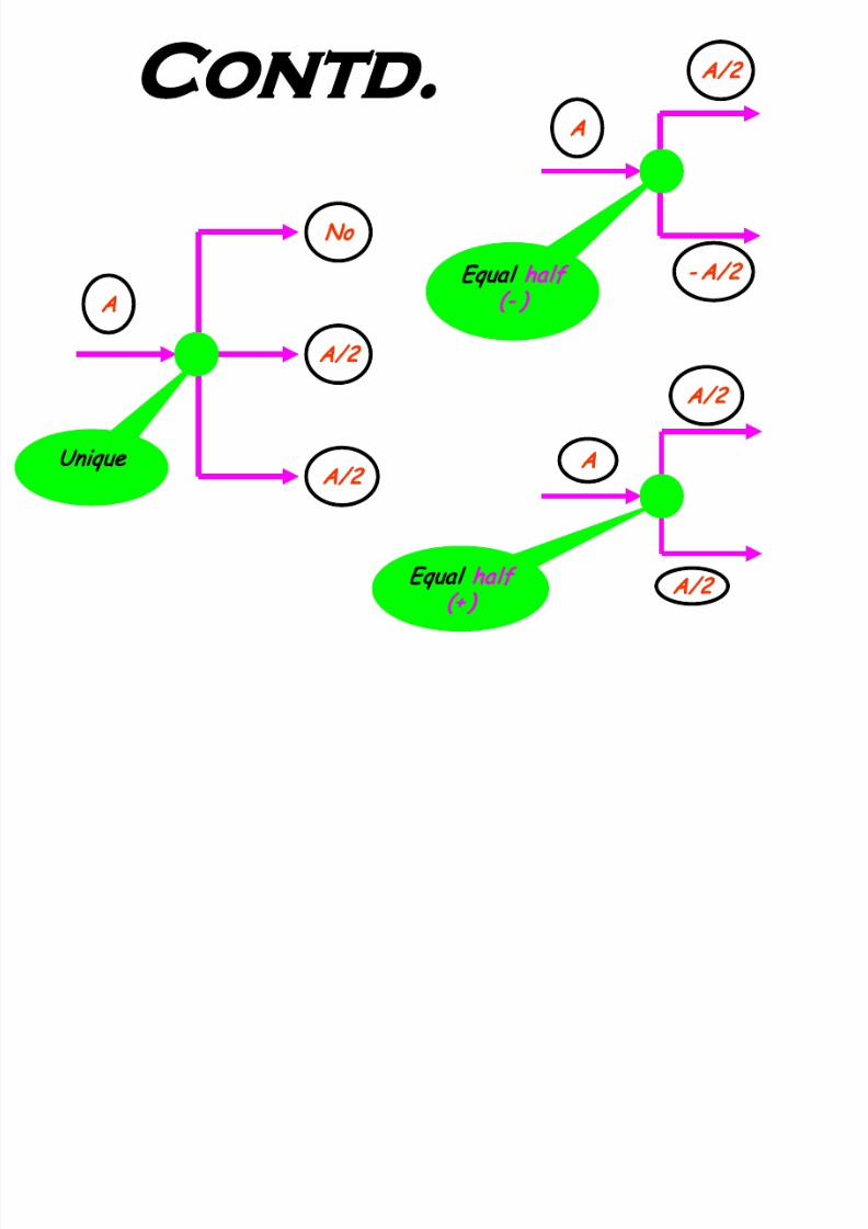
A- B
A
- B
Difference
Sum
A+ B
A
B
How to Regulate?
Various Possibilities are:
7/23/2019 Microwave Unit 1
http://slidepdf.com/reader/full/microwave-unit-1 47/141
Contd.
A
A/2
A/2
No
Unique
A
A/2
-A/2
qual half
(- )
A
A/2
A/2
qual half
(+ )

7/23/2019 Microwave Unit 1
http://slidepdf.com/reader/full/microwave-unit-1 48/141
Study
Plan
Construction
How do they work?
Applications aspects
Wave guide Components

7/23/2019 Microwave Unit 1
http://slidepdf.com/reader/full/microwave-unit-1 49/141
E & H-plane tees
These are the three port passive
devices
E-plane tee outputs are out of phase
H-plane tee outputs are in phase
Tees are used, when it is required to
combine two signals or split signal into
two parts in a µwave system
Ref: Kennedy Book; pp. 343-344 and Lio Book; pp. 144-146

7/23/2019 Microwave Unit 1
http://slidepdf.com/reader/full/microwave-unit-1 50/141

7/23/2019 Microwave Unit 1
http://slidepdf.com/reader/full/microwave-unit-1 51/141
Operation
Case-I: Feed in side arm
In
Out
Out
1
2
3
While passing
through the
junction, E-lines of
force bend as a
result of this, field
o f op po site p ola rity
emerge from t he two
main arms.
A
A/2
-A/2
F n . Dia gr am:
Outputs are equal but out of phase

7/23/2019 Microwave Unit 1
http://slidepdf.com/reader/full/microwave-unit-1 52/141
Contd.
A/2+A/2 =A
A/2
A/2
3
21
A/2+A/2
A/2
A/2
Case-II: T wo feeds in main arm
Outputs (Sum)

7/23/2019 Microwave Unit 1
http://slidepdf.com/reader/full/microwave-unit-1 53/141
H-plane tee—
Construction
An H-plane tee is
designed by
fastening a small
piece waveguide to
the narrow er arm of
the main waveguide
Side arm axis is
parallel to the
planes of H-field of
main guide
Side
arm
Main
arm
3
1 2

7/23/2019 Microwave Unit 1
http://slidepdf.com/reader/full/microwave-unit-1 54/141
3
1
2
Operation
Reason Being…..
While passing through the junction (H-plane) the
E-field d oes not suffer any bending and consequently
th e ju nction split on e wav e in two equal h alf (in phase)
Case-I: Feed in side arm
Outputs are equal b ut in p ha se
A
A/2
A/2
F n . Dia gr am:

7/23/2019 Microwave Unit 1
http://slidepdf.com/reader/full/microwave-unit-1 55/141
Contd.
.
Out
In
In
3
1
2
Case-II: T wo feeds in main arm
Outputs (Sum)

7/23/2019 Microwave Unit 1
http://slidepdf.com/reader/full/microwave-unit-1 56/141
Hybrid tee
(Magic Tee)
4-port low loss passive device
Combined E-plane and H-plane tees
Power divided/combined among various
ports in peculiar way
Magic ≡ unusual manner
a
a/2
a/2
0
(
a+b)/2
a
b
(
a- b)/2
Power divided in Unusual way Power combined in Unusual way
Ex:

7/23/2019 Microwave Unit 1
http://slidepdf.com/reader/full/microwave-unit-1 57/141
4
2 3
1
E-arm
H-arm
Hybrid tee (Magic
Tee)--Construction
H yb rid T ee = E+H t ee s
E-arm feed is not noticed
a t H -a rm a nd v ic e v er sa.
7/23/2019 Microwave Unit 1
http://slidepdf.com/reader/full/microwave-unit-1 58/141
4
2
3
1
a/2
a
a/2
0
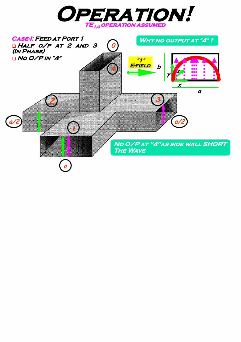
Operation
Wh y no output at ″4″ ?
No O/ P at "4"as side wall SHORT
The Wave
Case-I: Feed at Port 1
Half o/p at 2 and 3
(In Phase)
No O/P in
″
4
″
TE
1,0
operation assumed
a
x
y
z
″1″
E-field

7/23/2019 Microwave Unit 1
http://slidepdf.com/reader/full/microwave-unit-1 59/141
4
2
3
1
a
-a/2
No
a/2
Contd..
Case-II: Feed in E - arm ″4″
O utputs are equal but
out of phase in ″2″ & ″3″
No O/P in ″1″
HW
No O/P at “1"as Broader wall
SHO RT The Wave
F n . D iagr am
7/23/2019 Microwave Unit 1
http://slidepdf.com/reader/full/microwave-unit-1 60/141
4
2 3
1
a
b
Sum/2
Difference/2
E-
arm
H-
arm
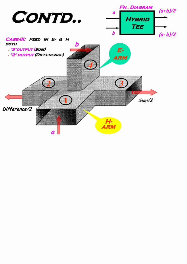
Contd..
Case-III:
Feed in E- & H
both
″3″output (Sum)
″2″
output (Difference)
Hybrid
Tee
a
b
(a+b)/2
(a- b)/2
Fn . D iagr am

7/23/2019 Microwave Unit 1
http://slidepdf.com/reader/full/microwave-unit-1 61/141
4
2 ,
1
a/2
a
No
a/2
Contd..
Hybrid
Tee
a
No
+a/2
+a/2

7/23/2019 Microwave Unit 1
http://slidepdf.com/reader/full/microwave-unit-1 62/141
4
2 3
1
- a /2
a
No
a/2
Contd..
Hybrid
Tee
a
No
+a/2
-a/2
F n . D iagr am

7/23/2019 Microwave Unit 1
http://slidepdf.com/reader/full/microwave-unit-1 63/141
Applications
Use for high power
applications
As a Mixer in RADAR receivers
Can be used to add two Tx
power to achieve higher range

7/23/2019 Microwave Unit 1
http://slidepdf.com/reader/full/microwave-unit-1 64/141
Add 2-Tx Power
T
x1
T
x2
T
x2
+ T
x1
TeeS
T
x1
T
x2
T
x1
T
x2
T
x2
+ T
x1
2-Tx
powers
have
been
Added
7/23/2019 Microwave Unit 1
http://slidepdf.com/reader/full/microwave-unit-1 65/141
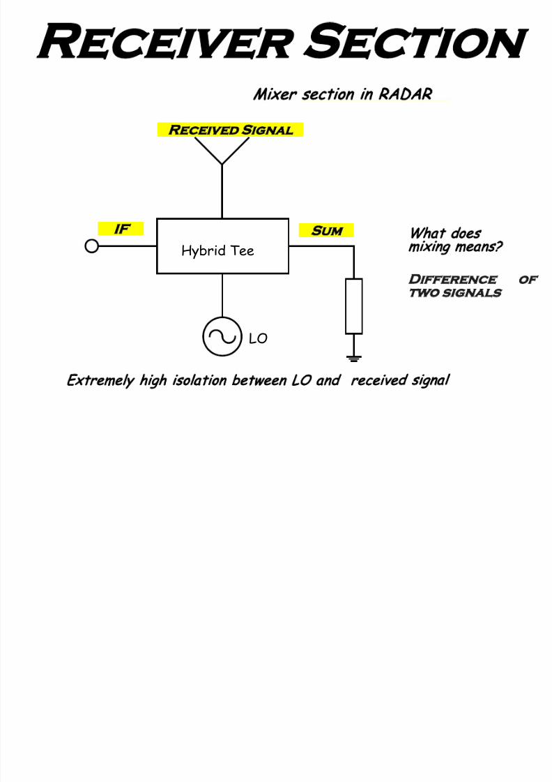
Receiver Section
Mixer section in RADAR
Extreme ly high isolation between LO and received signal
What does
mixing means?
Difference of
two signals
Tx
LO
Hybrid Tee
Received Signal
Sum
F

7/23/2019 Microwave Unit 1
http://slidepdf.com/reader/full/microwave-unit-1 66/141
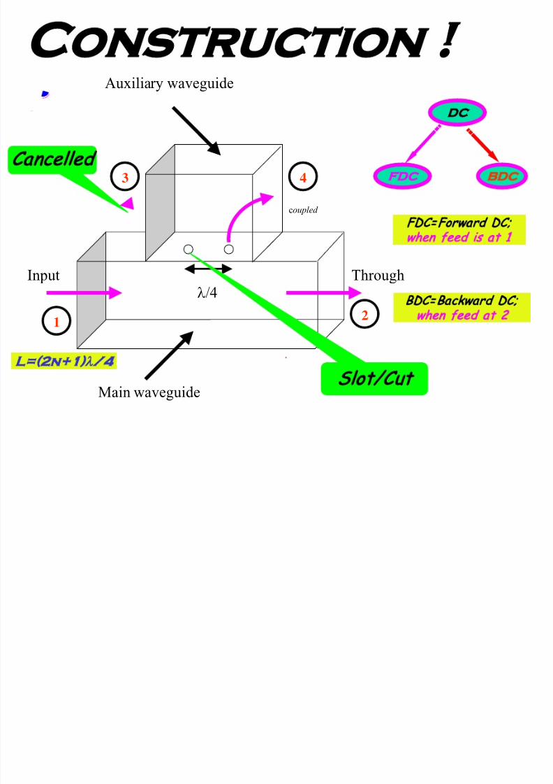
Directional Coupler
A four-port passive low loss
device
Used to split some of the power of
main guide into secondary guide
Used for monitoring of the
RF/Microw ave pow er flow in main
guide line while introducing
minimum perturbation
Ref: Lio Book (3rd ED); pp. 149-154
7/23/2019 Microwave Unit 1
http://slidepdf.com/reader/full/microwave-unit-1 67/141
Construction
λ/4
ThroughInput
Main waveguide
Auxiliary waveguide
21
43
Isolat ed
coupled
Slot/Cut
L=(2n+1)λ/4
Cancelled
DC
FDC BDC
FDC=Forward DC;
when feed is at 1
BDC=Backward DC;
when feed at 2
7/23/2019 Microwave Unit 1
http://slidepdf.com/reader/full/microwave-unit-1 68/141
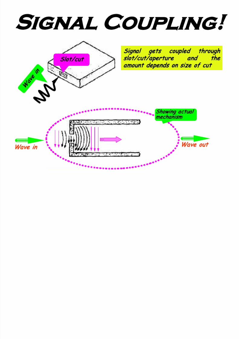
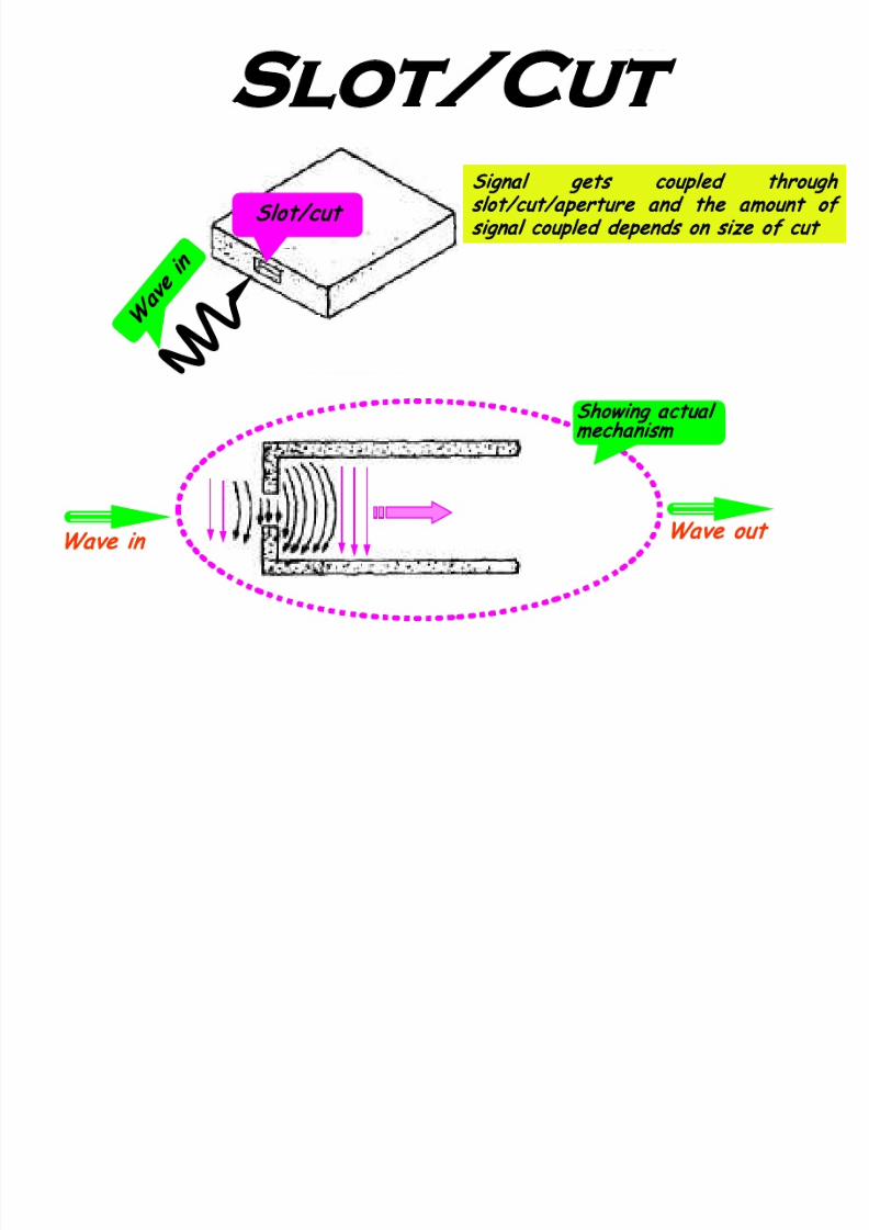
Signal Coupling
Signal gets coupled through
slot/cut/aperture and the
amount depends on size of cut
Slot/cut
Wave in
Wave out
Showing actual
mechanism

7/23/2019 Microwave Unit 1
http://slidepdf.com/reader/full/microwave-unit-1 69/141
Symbol
Ex: T=Through 0.99Pin ; C=C oupled 0.01Pin ; I=Isolated 0.0
T = Most of the power ; C = Fraction of the power ; I = Almost no power
3
4
1
2
Pin
I
T
C
7/23/2019 Microwave Unit 1
http://slidepdf.com/reader/full/microwave-unit-1 70/141
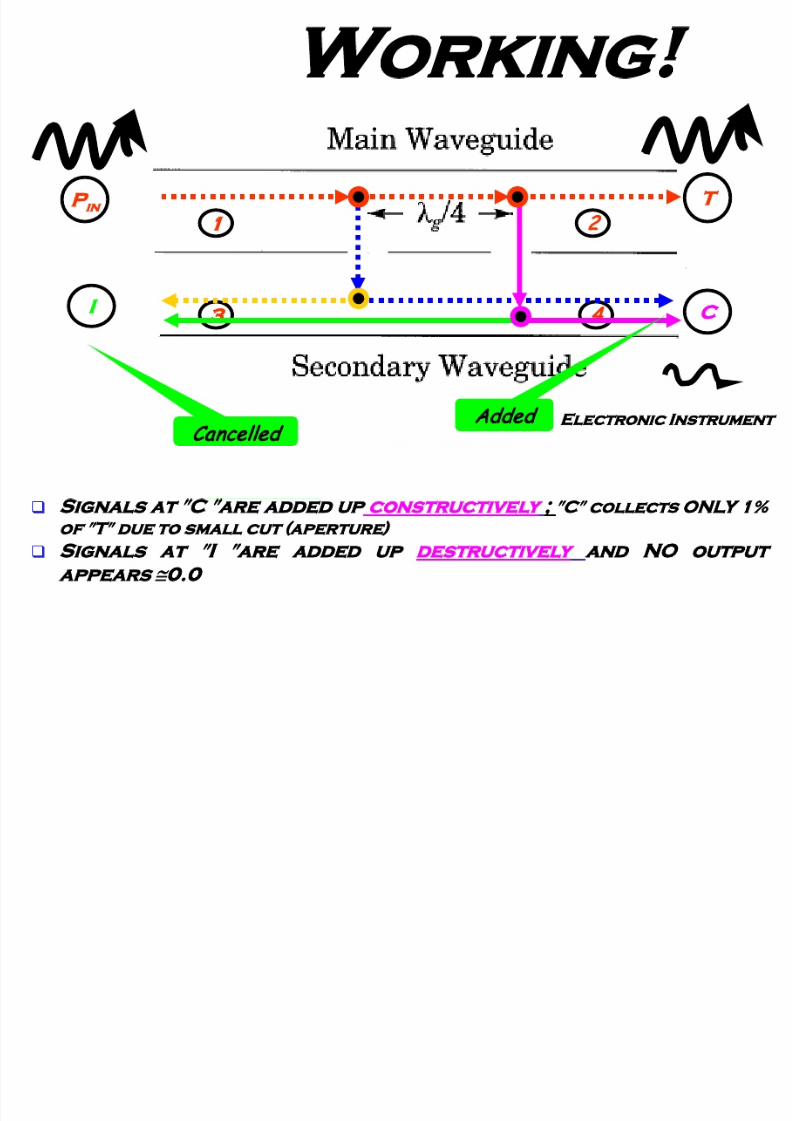
Working
1
3
2
4
C
Electronic Instrument
T
in
Added
Cancelled
Signals at ″C ″are added up constructively ; ″
C
″
collects ONLY 1%
of ″T″ due to sma ll cut (a perture)
Signals at
″
I
″
are added up destructively and NO output
appears 0.0
7/23/2019 Microwave Unit 1
http://slidepdf.com/reader/full/microwave-unit-1 71/141
Slot/Cut
Signal gets coupled through
slot/cut/a perture and the a mount of
signa l coupled depends on size of cut
lot/cut
Wave in
Wave out
Showing actual
mechanism

7/23/2019 Microwave Unit 1
http://slidepdf.com/reader/full/microwave-unit-1 72/141
FoM
×
=
3
4
4
1
3
1
P
P
P
P
P
P
4110 P Plog10C(dB) =
Coupling factor (C) - The ratio of input power to the coupled power
3 410 P Plog10 D(dB)=
Directivity (D)- The ratio forward power (coupled port ) to the
backward power (isolated port)
3110 P Plog10 I(dB)=
Isola tion factor (I) – The ratio of input power to power at the isolated port
C D I
Expressed
in dB
P erformance of DC is d ecid ed by C , D & I

7/23/2019 Microwave Unit 1
http://slidepdf.com/reader/full/microwave-unit-1 73/141
With known value of ″C″
(manufacturer Supplied)
Application
(Pow er M onitoring)
A fraction of power measured
at
″
P
4
″
could Determine the
Main power
Try problem 4-26 of Lio Book (3rd ED); pp. 164-165
7/23/2019 Microwave Unit 1
http://slidepdf.com/reader/full/microwave-unit-1 74/141
Hybrid rings
(Rat-Race )
Four port passive low loss device
Constructed from rectangular
guide but molded into circular
shape
Used in high power RADAR and
communications equipments

7/23/2019 Microwave Unit 1
http://slidepdf.com/reader/full/microwave-unit-1 75/141
Construction
1
4
2
3λ/4
λ/4
λ
/4
λ/4
Looks
quite
different
from
magic tee
But
perform
very
similar to
magic tee
S hape is lik e a rin g
a/2
Fn. Diagram
7/23/2019 Microwave Unit 1
http://slidepdf.com/reader/full/microwave-unit-1 76/141
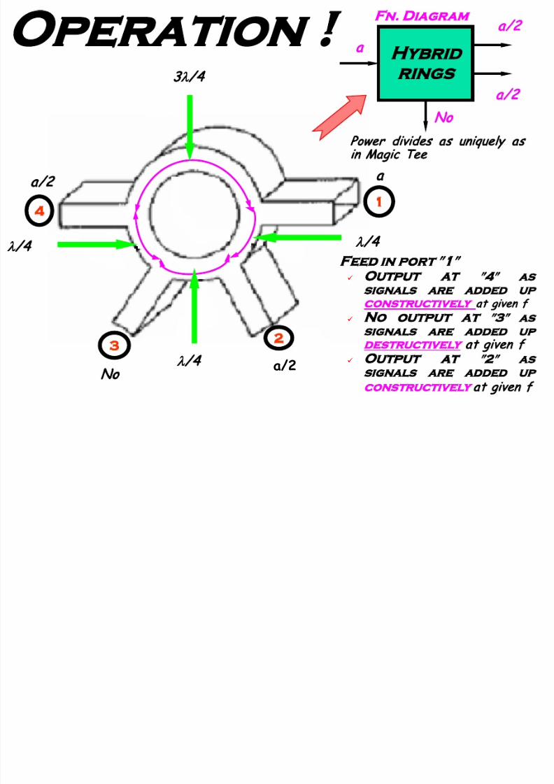
4
2
3
3
λ
/4
λ
/4
λ
/4
λ
/4
a
a/2No
a/2
Operation
F eed in p or t
″
1
″
Output at ″4″ as
signals are added up
constructively
at given f
N o output at
″
3
″
as
signals are added up
destructively
at given f
Output at ″
2
″
as
signals are added up
constructively
at given f
Hybrid
rings
a
No
a/2
Power divides as uniquely as
in Magic Tee

7/23/2019 Microwave Unit 1
http://slidepdf.com/reader/full/microwave-unit-1 77/141
W hy the name Rat-
Race?
O/P is the net
results of
two signal
races -- one
clockwise and
other in anti
clockwise
O/P

7/23/2019 Microwave Unit 1
http://slidepdf.com/reader/full/microwave-unit-1 78/141
Application
4
2
3
3
λ
/4
λ
/4
λ
/4
λ/4
Tx
Antenna
No
Load
Tx Power is divided up into
Antenna & Load

7/23/2019 Microwave Unit 1
http://slidepdf.com/reader/full/microwave-unit-1 79/141
Bends & Corners
Transition through the bend and corner are made gradually
to…….
…. Minimize reflection and loss of power
Bends &
Corners
θ
These components are used to ALTER the direction of the
wave by an arbitrary angle…
They are E- type, when bends along E- plane and H- type
when bends a long H- plane…

7/23/2019 Microwave Unit 1
http://slidepdf.com/reader/full/microwave-unit-1 80/141
Bends
These components bend smoothly a long E or H- pla ne
E- bends bend along E- pla ne, wherea s H- bends along H- pla ne.
E- plane
bend
H- fields a re disturb as bend is
a long shorter wall
H- plane
bend
E- fields are disturb as bend
is a long broader wa ll
Bends are designed with radius r> 2
λ
……
…. . Minimize reflection

7/23/2019 Microwave Unit 1
http://slidepdf.com/reader/full/microwave-unit-1 81/141
Corners
L=(2n+1)
λ
/4 n= 0, 1 , 2, 3, ……. to minimize reflection
Facilitates change along E- plane Facilitates change along H- plane
Purpose of corner is same as that of bend i. e. to change the
direction of the µ wave by an arbitrary angle
L
E- plane
corner
L
H- plane
corner
For the larger wavelength a bend is rather clumsy, and a corner is used
instead
Like Bends, Corners are also of E & H- type
7/23/2019 Microwave Unit 1
http://slidepdf.com/reader/full/microwave-unit-1 82/141
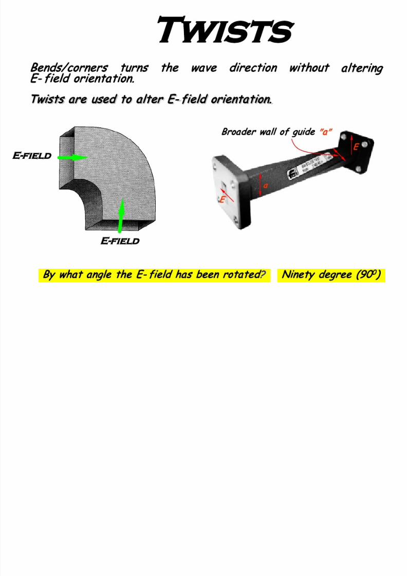
Twists
Broader wall of guide
″
a
″
E
a
E
Bends/corners turns the wave direction without altering
E- field orientation.
E-field
E-field
Twists are used to a lter E- field orientation.
By what angle the E- field has been rotated? Ninety degree (90
0
)
7/23/2019 Microwave Unit 1
http://slidepdf.com/reader/full/microwave-unit-1 83/141
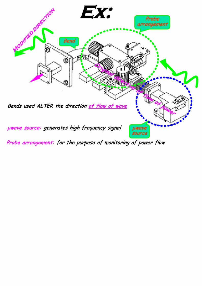
µ
wave
source
Ex:
Bend
Bends used ALTER the direction of flow of wave
Probe
arrangement
µ
wave source: generates high frequency signal
Probe arrangement: for the purpose of monitoring of power flow

7/23/2019 Microwave Unit 1
http://slidepdf.com/reader/full/microwave-unit-1 84/141
In µwave system, load reflects power and affects the generatorstability, in such scenario devices like Circulator & Isolator are usedbetween generator and load to improve the system stability
Generator
Load
R
L
Stability Issue
These are non-reciprocal passive µwave devices Improve the stability by providing unidirectional power flow
Ref: Lio Book (3rd ED); pp. 158-161

7/23/2019 Microwave Unit 1
http://slidepdf.com/reader/full/microwave-unit-1 85/141
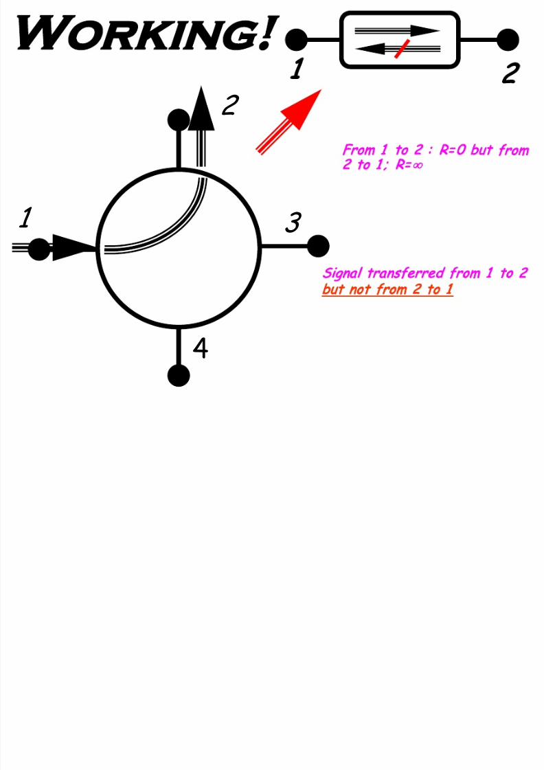
Symbol
3 4
1
4
3
2
1
2
3
4
Circulator
µwave circulator is a non-reciprocal Multi-port passive device Work on Sequential transmission, where input applied at port
″
n″
comes out at “next i.e. n+1 port″ but not out at ANY other port
3 4
Ref: Lio Book (3rd
ED); pp. 158-161

7/23/2019 Microwave Unit 1
http://slidepdf.com/reader/full/microwave-unit-1 86/141
Sequential Flow
3
4
2
1
7/23/2019 Microwave Unit 1
http://slidepdf.com/reader/full/microwave-unit-1 87/141
Working
Signal transferred from 1 to 2
but not from 2 to 1
1
2
1
2
4
3
From 1 to 2 : R= 0 but from
2 to 1 ; R=
∞
7/23/2019 Microwave Unit 1
http://slidepdf.com/reader/full/microwave-unit-1 88/141
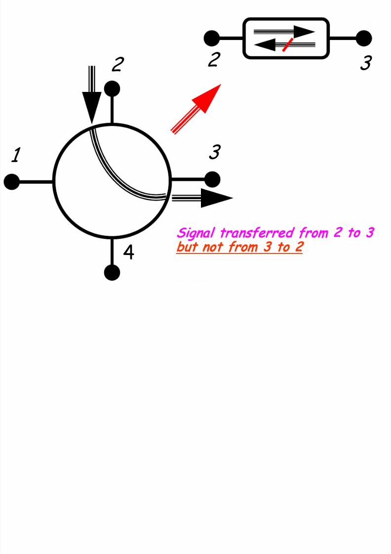
1
4
3
2 2 3
Signal transferred from 2 to 3
but not from 3 to 2

7/23/2019 Microwave Unit 1
http://slidepdf.com/reader/full/microwave-unit-1 89/141
1
4
3
2
3 4
Signal transferred from 3 to 4 but not
from 4 to 3
7/23/2019 Microwave Unit 1
http://slidepdf.com/reader/full/microwave-unit-1 90/141
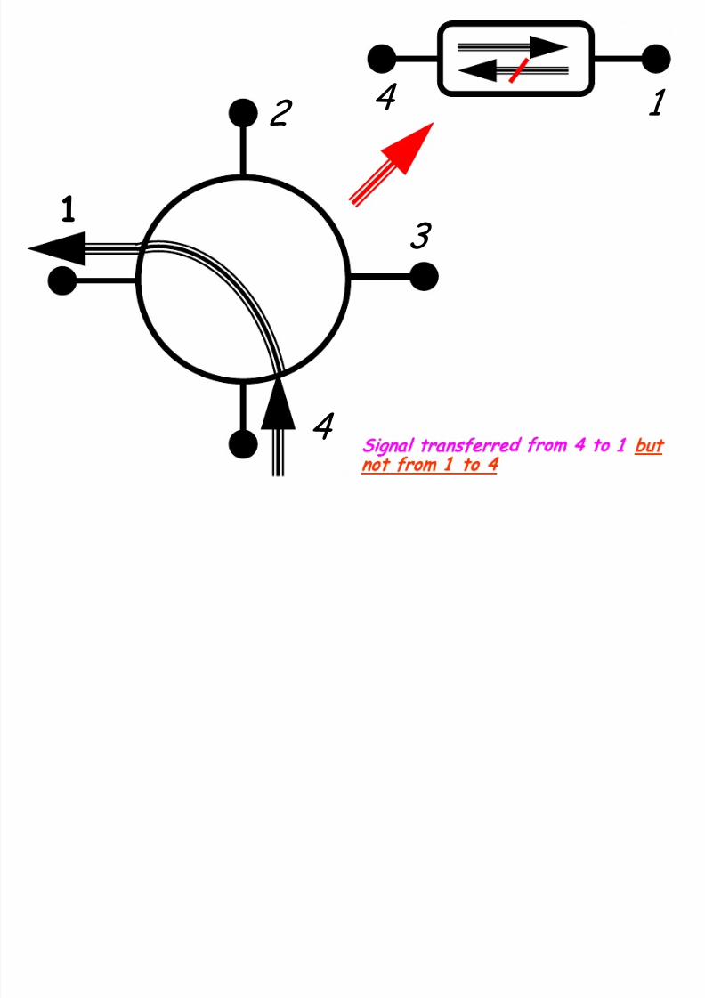
1
4
3
2 1 4
Signal transferred from 4 to 1 but
not from 1 to 4

7/23/2019 Microwave Unit 1
http://slidepdf.com/reader/full/microwave-unit-1 91/141
Circulator with N=3
1 2 3 1
HW
a signal applied to port 1 only comes out of port 2; a signal
applied to port 2 only comes out of port 3; a signal applied to
port 3 only comes out of port 1
7/23/2019 Microwave Unit 1
http://slidepdf.com/reader/full/microwave-unit-1 92/141
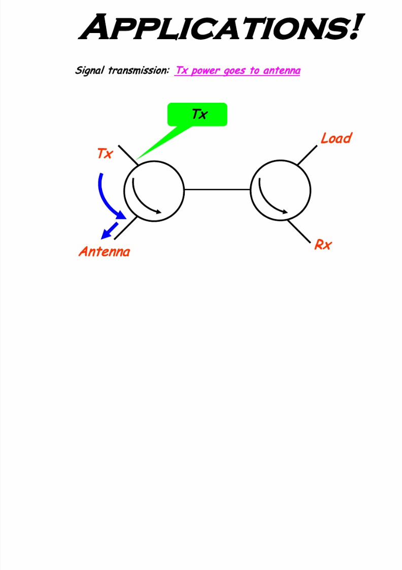
Applications
Signal transmission: Tx power goes to antenna
Antenna
Tx
Load
Rx
Tx

7/23/2019 Microwave Unit 1
http://slidepdf.com/reader/full/microwave-unit-1 93/141
Signal Reception
Antenna power goes to receiver
Antenna
Tx
Load
Rx
Rx
Tx & Rx connected to a single antenna have been isolated
7/23/2019 Microwave Unit 1
http://slidepdf.com/reader/full/microwave-unit-1 94/141
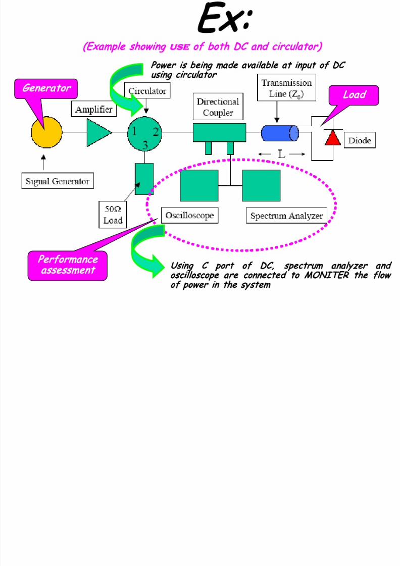
(Example showing
use
of both DC and circulator)
Ex:
Performance
assessment
Load
enerator
Power is being made available at input of DC
using circulator
Using C port of DC, spectrum analyzer and
oscilloscope a re connected to MON ITER the flow
of power in the system
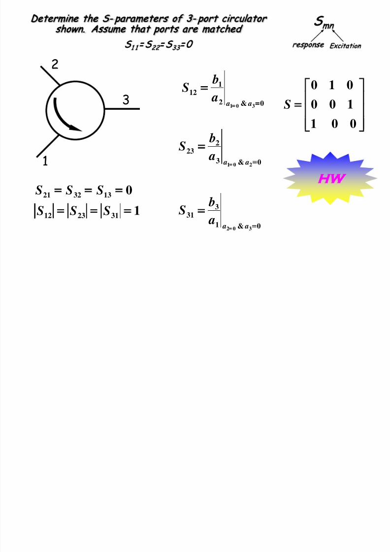
Determine the S- parameters of 3- port circulator shown.
S

7/23/2019 Microwave Unit 1
http://slidepdf.com/reader/full/microwave-unit-1 95/141
2
1
3
0&1
221
302 =
=
a a a
bS
50
Ω
50Ω
S
1 1
= S
22
= S
33
= 0
2
1
3
50Ω
0&2
332
301 =
=
a a a
bS
Assume that ports a re matched
Excitation
esponse
mn
S
mn
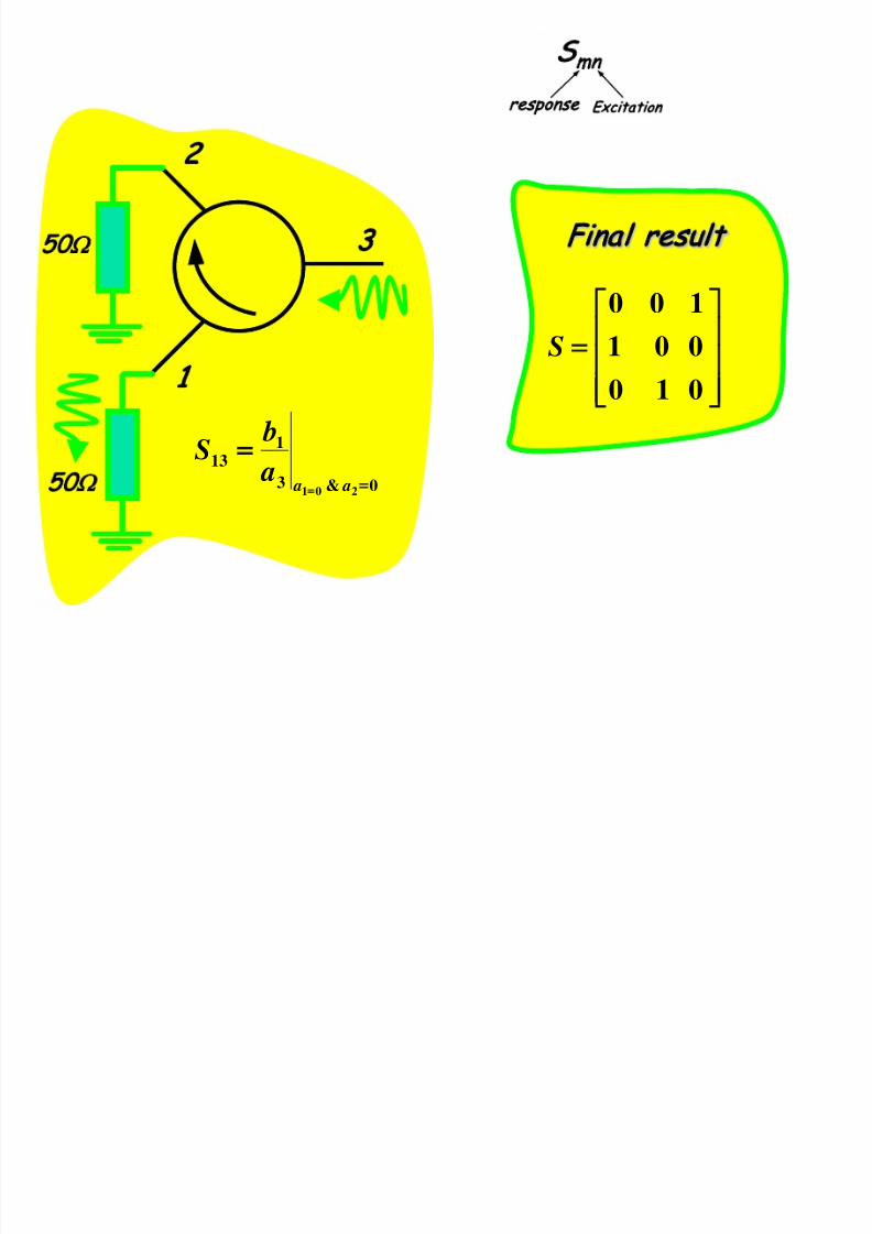
7/23/2019 Microwave Unit 1
http://slidepdf.com/reader/full/microwave-unit-1 96/141
Excitation
esponse
2
1
3
0Ω
50
Ω
0&3
113
201 =
=
a a a
bS
=
0 1 0
0 0 1
1 0 0
S
Final result
S
mn
Determine the S- parameters of 3- port circulator
shown. Assume that ports are matched
7/23/2019 Microwave Unit 1
http://slidepdf.com/reader/full/microwave-unit-1 97/141
2
1
3
1
0
312312
133221
=
=
SSS
SSS
0&2
112
301 =
=
a a a
bS
0&3
223
201 =
=
a a a bS
0&1
331
302 =
=
a a a
b
S
=
0 0 1
1 0 0
0 1 0
S
Excitation
esponse
HW
S
1 1
= S
22
= S
33
= 0

7/23/2019 Microwave Unit 1
http://slidepdf.com/reader/full/microwave-unit-1 98/141
Isolator
Isolator is a 2-port passive
device
Allows one way flow of power
in µwave system
Improve the stability of
µ
wave
generator
Ref: Lio Book (3rd ED); pp. 160-161

7/23/2019 Microwave Unit 1
http://slidepdf.com/reader/full/microwave-unit-1 99/141
L
E
E
×
×
×
×
×
×
×
×
×
×
×
θ
H
Working
Angle of rotation
θ
depends on:
length of ferrite rod
diameter of rod
strength of applied magnetic field
strength “H”
Ferrite rod
Works on the concept of Faraday Rotation
Ferrite rod could be designed to make θ= 45
0
When e. m. waves are launched through some specia l ferrite
materia l, then their pola rization is rotated by an angle θ
These materia ls are Magnese Ferrite (MnFe2O3), Zinc Ferrite (ZnFe2O3)
ISOLATOR
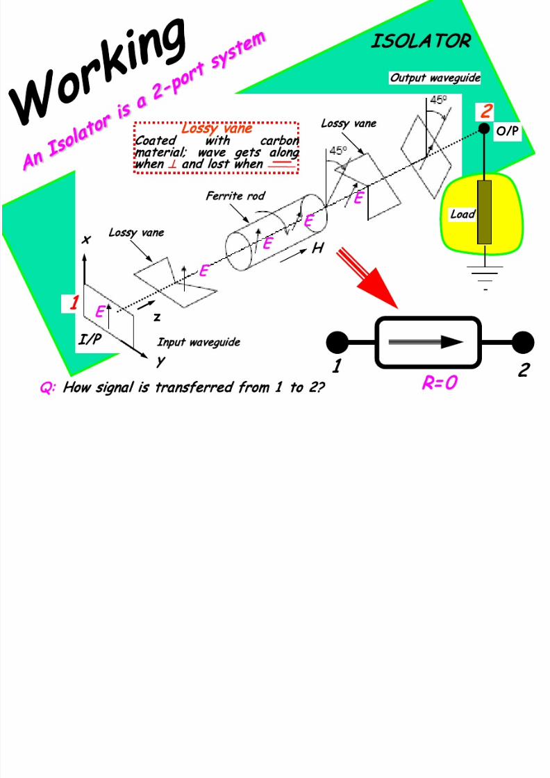
7/23/2019 Microwave Unit 1
http://slidepdf.com/reader/full/microwave-unit-1 100/141
x
y
z
E
E
E
E
Lossy vane
Ferrite rod
H
Lossy vane
I/P
Output waveguide
1
2
Input waveguide
O/P
Load
Lossy vane
Coated with carbon
material; wave gets along
when ⊥ a nd lost when
1
2
R= 0
: How signal is transferred from 1 to 2?
7/23/2019 Microwave Unit 1
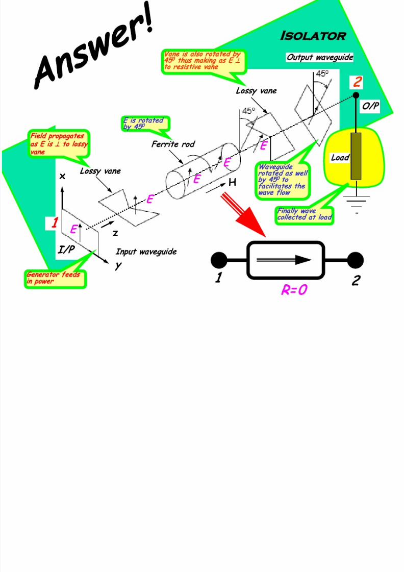
http://slidepdf.com/reader/full/microwave-unit-1 101/141
x
y
z
E
E
E
E
Lossy vane
Ferrite rod
H
Lossy vane
I/P
Output waveguide
1
2
Input waveguide
O/P
Isolator
Load
1
2
R= 0
Field propagates
as E is
⊥
to lossy
vane
E is rotated
by 45
0
Vane is also rotated by
45
0
thus making as E
⊥
to resistive vane
Waveguide
rotated as well
by 45
0
to
facilitates the
wave flow
Finally wave
collected at load
Generator feeds
in power
As reverse signa l is a ligned to lossy va ne
and no signa l rea ch to the genera tor

7/23/2019 Microwave Unit 1
http://slidepdf.com/reader/full/microwave-unit-1 102/141
x
y
z
Lossy vane
Ferrite rod
H
Lossy vane
Input waveguide
Output waveguide
Load
1
2
ref wave
ref wave—add 45
0
ref wave—LOST
No signal transfer from 2 to 1
1
2
=∞
Reflected wave get
in to O/P guide
Ferrites rod further
rotate the wave by
an angle of 45
0
E now become parallel
to vane and get LOST
All waves are not
collected a nd some of
them a re ref ba ck
ref waves do not
reach the Gen
These devices have Loss
1 dB and Isola tion
40dB
7/23/2019 Microwave Unit 1
http://slidepdf.com/reader/full/microwave-unit-1 103/141
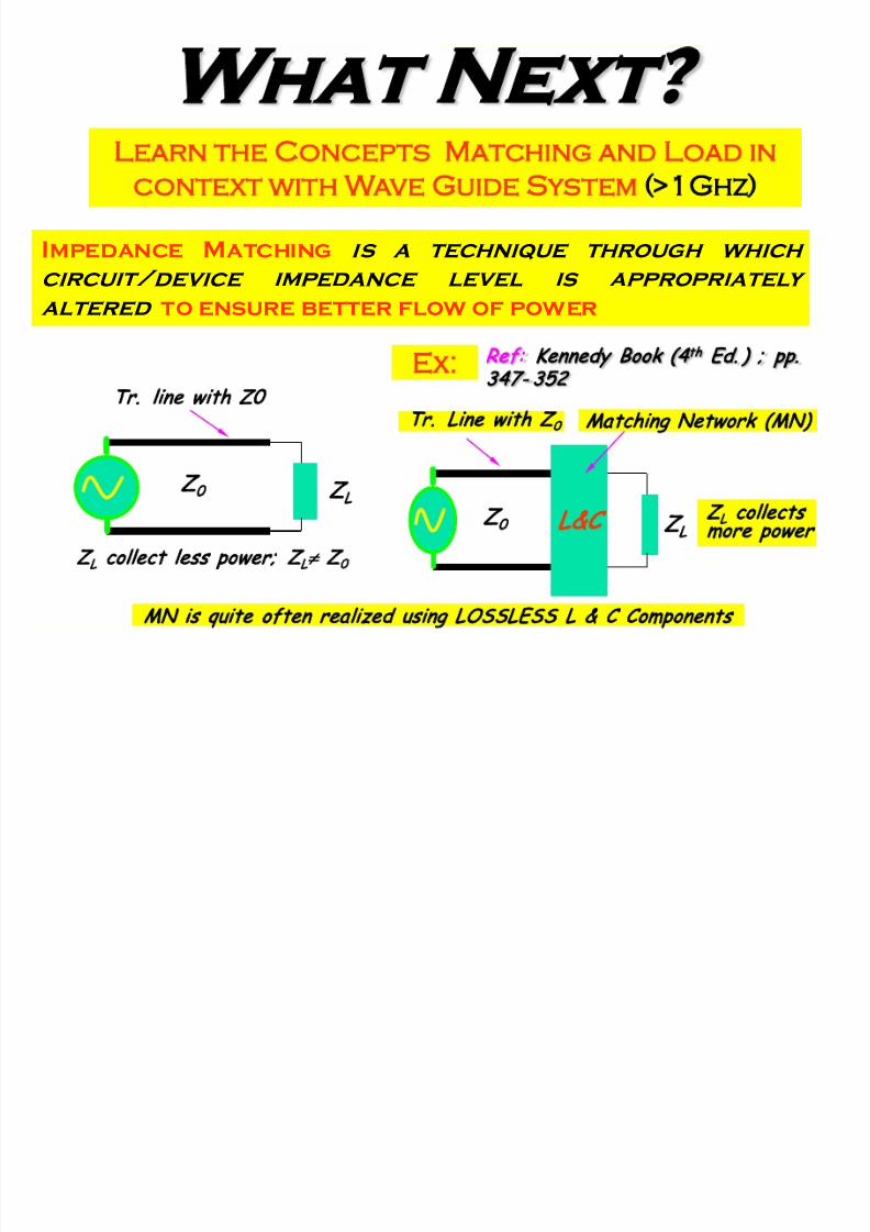
W hat Next?
Learn the Concepts Matching and Load in
context with Wave Guide System >1Ghz)
Impedance Matching is a technique through which
circuit/device impedance level is appropriately
altered to ensure better flow of power
MN is quite often rea lized using LOSSLESS L & C Components
Z
0
Z
L
Z
L
collect less power; Z
L
≠
Z
0
Tr. line with Z0
Z
0
Z
L
&C
Matching Network (MN)
Z
L
collects
more power
Tr. Line with Z
0
Ex:
Ref: Kennedy Book (4
th
Ed.) ; pp.
347- 352
7/23/2019 Microwave Unit 1
http://slidepdf.com/reader/full/microwave-unit-1 104/141
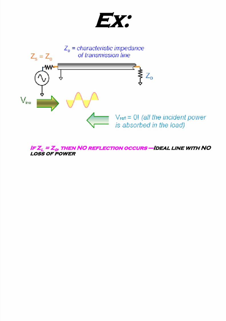
Ex:
If Z
L
= Z
0
, then N O r eflection occurs ----Ideal line with NO
loss of power

7/23/2019 Microwave Unit 1
http://slidepdf.com/reader/full/microwave-unit-1 105/141
Standing w ave pattern results w hen Z
L
≠ Z
0
--- N ot m atched
a nd p ow er loss d oe s o cc ur
Ex:
Standingwave

7/23/2019 Microwave Unit 1
http://slidepdf.com/reader/full/microwave-unit-1 106/141
W aveguide System
Like transmission line, wave guide systems (> 1 GHz) are to be
impedance matched to the loads………in order to minimize
reflection
For frequency < 1 GHz, matching elements are realized using
lumped L & C……
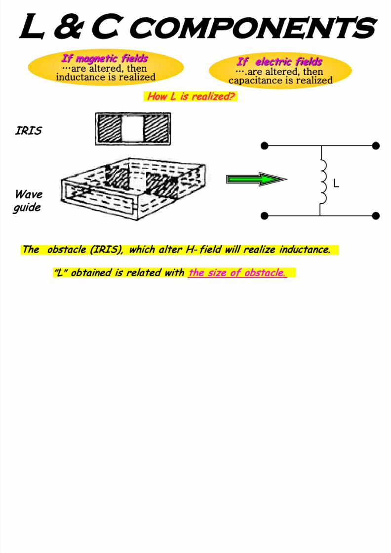
How these elements (L& C) are realized at µwave (> 1 GHz)?
These are rea lized using wave guide components ca lled ″IRIS″

7/23/2019 Microwave Unit 1
http://slidepdf.com/reader/full/microwave-unit-1 107/141
7/23/2019 Microwave Unit 1
http://slidepdf.com/reader/full/microwave-unit-1 108/141

7/23/2019 Microwave Unit 1
http://slidepdf.com/reader/full/microwave-unit-1 109/141
7/23/2019 Microwave Unit 1
http://slidepdf.com/reader/full/microwave-unit-1 110/141
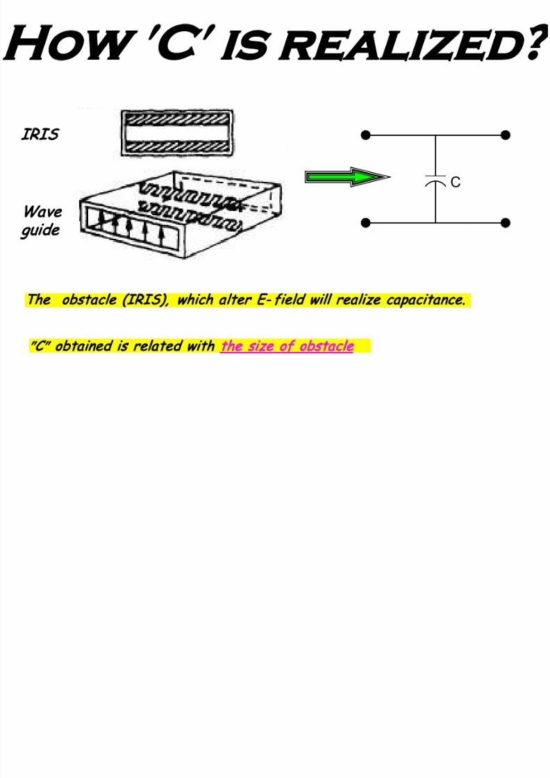
IRIS
Wave
guide
′C ′ is realized
The obstacle (IRIS), which a lter E- field w ill rea lize capacitance.
″
C
″
obta ined is related with the size of obstacle
C
7/23/2019 Microwave Unit 1
http://slidepdf.com/reader/full/microwave-unit-1 111/141
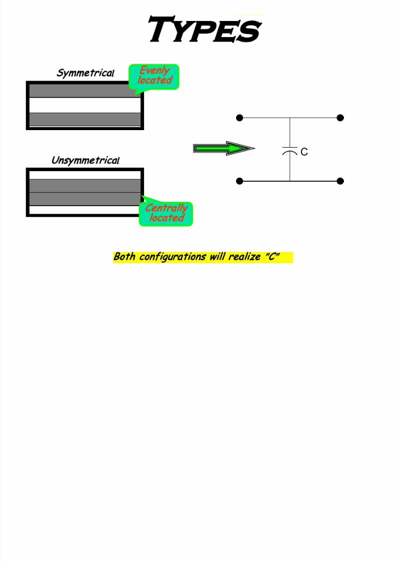
Types
Unsymmetrical
Centrally
located
Symmetrica
l
Evenly
located
Both configurations will realize
″
C
″
C

7/23/2019 Microwave Unit 1
http://slidepdf.com/reader/full/microwave-unit-1 112/141
7/23/2019 Microwave Unit 1
http://slidepdf.com/reader/full/microwave-unit-1 113/141
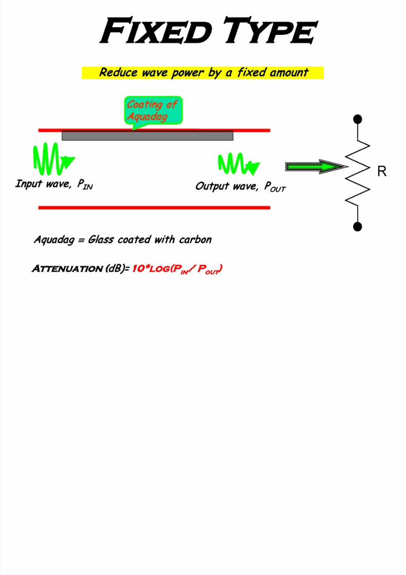
Fixed Type
Attenuation (dB)= 10*log(P
in
/ P
out
)
Output wave, P
OUT
Input wave, P
IN
Coating of
Aquadag
Reduce wave power by a fixed amount
Aquadag ≡ Glass coated with carbon
R
Variable Type
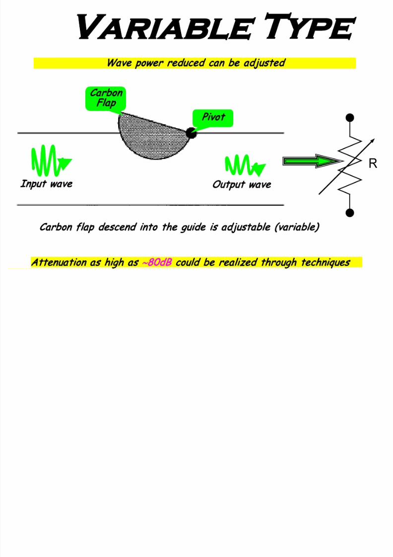
7/23/2019 Microwave Unit 1
http://slidepdf.com/reader/full/microwave-unit-1 114/141
Input wave
Output wave
Pivot
Carbon
Flap
Attenuation a s high as
∼
80dB could be realized through techniques
Carbon flap descend into the guide is adjustable (variable)
Wave power reduced can be adjusted
R
W aveguide Loads

7/23/2019 Microwave Unit 1
http://slidepdf.com/reader/full/microwave-unit-1 115/141
Taper edge gives rise gradua l impedance transition and reduced reflection
Load is similar to attenuator but normally kept at the end of guide
If tapered on both the ends, then it called double tapered (DT)
Load depends on dielectric of lossy materia l used
R
≈ 2λ
≈ λ/2
Lossy
material
Single
tapered

7/23/2019 Microwave Unit 1
http://slidepdf.com/reader/full/microwave-unit-1 116/141

7/23/2019 Microwave Unit 1
http://slidepdf.com/reader/full/microwave-unit-1 117/141
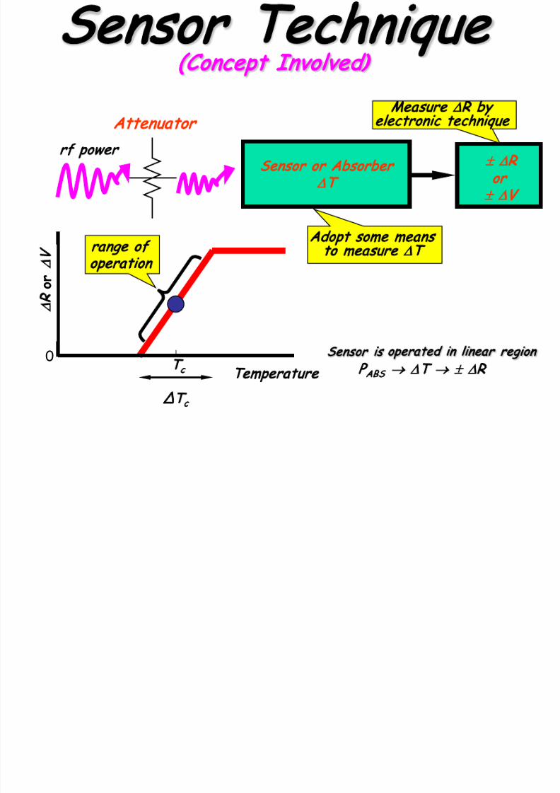
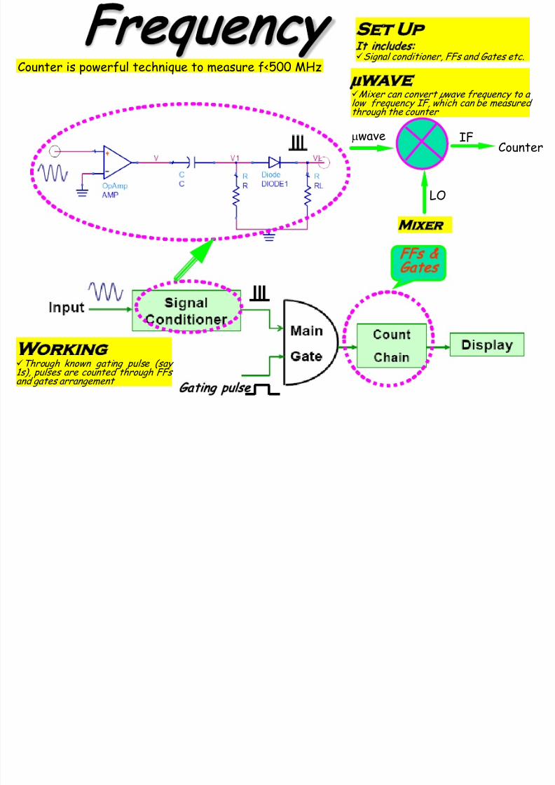
Basic rules
Know which quantity you wish to measure
Proper test arrangement i. e. equipments
required
sources: oscillator…. .
detectors: power meter, spectrum analyzer, network
analyzer…. .
auxiliary devices: attenuator, directional coupler…. .
Should be familiar with how to carry out a
particular experiment
Learn how to interpret various results
Take appropriate precaution due to high
frequency involved
7/23/2019 Microwave Unit 1
http://slidepdf.com/reader/full/microwave-unit-1 118/141
Types

7/23/2019 Microwave Unit 1
http://slidepdf.com/reader/full/microwave-unit-1 119/141
Sensor Techniques
Calorimeter
Bolometer
Thermocouple
Themistor
NTC (-
R)
Barreter
PTC (+
R)
Measure (+
T)
Measure (
±
V )
Measure (
±
R )
NTC e.g. thermister & PTC e.g. barreter
Thermistor → Meta l oxide of
Ni, Mn, Co etc.
Baretter →
Metal like
platinum etc.

7/23/2019 Microwave Unit 1
http://slidepdf.com/reader/full/microwave-unit-1 120/141
Calorimeter
Used for high power
Work on absorption of microwave
power by fluid usually water
Measure the rise in temperature of
the fluid due to absorption of
rf/microwave power
Poor response time
Less accurate

7/23/2019 Microwave Unit 1
http://slidepdf.com/reader/full/microwave-unit-1 121/141

7/23/2019 Microwave Unit 1
http://slidepdf.com/reader/full/microwave-unit-1 122/141

7/23/2019 Microwave Unit 1
http://slidepdf.com/reader/full/microwave-unit-1 123/141
Bolometer
Temperature sensor resistor
Work on bridge circuit concept
Used to measure low power (< 1 mW)
Higher accuracy
Better sensitivity
Faster response time

7/23/2019 Microwave Unit 1
http://slidepdf.com/reader/full/microwave-unit-1 124/141
Working
7/23/2019 Microwave Unit 1
http://slidepdf.com/reader/full/microwave-unit-1 125/141
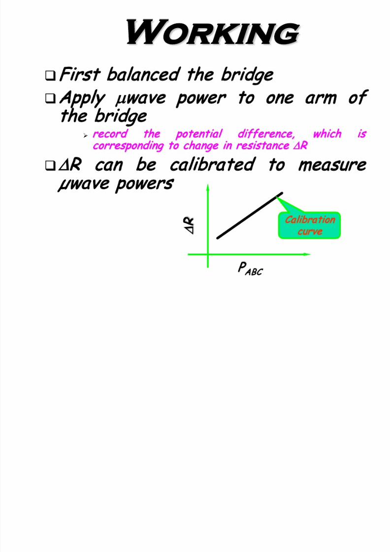
First ba lanced the bridge
Apply
µ
wave power to one arm of
the bridge
record the potential difference, which is
corresponding to change in resistance
R
R can be calibrated to measure
µwave powers
P
ABC
Calibration
curve
7/23/2019 Microwave Unit 1
http://slidepdf.com/reader/full/microwave-unit-1 126/141

7/23/2019 Microwave Unit 1
http://slidepdf.com/reader/full/microwave-unit-1 127/141
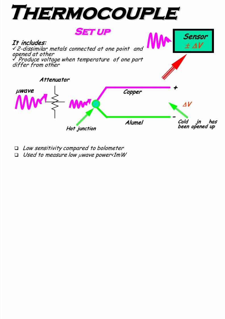
Working
Temperature difference at junctions induce
potentia l difference ( v) proportiona l to absorbed
power (P
ABC
) i. e. P
ABS
∝ v
Difference in voltage generated can be ca librated
to measure
µ
wave power
v
P
ABC
Calibration
curve
VSWR
MAX V
MIN V

7/23/2019 Microwave Unit 1
http://slidepdf.com/reader/full/microwave-unit-1 128/141
VSWR gives
measure of
degree of
mismatch on line,
which manifests
in terms of SWP
Standing wave
pattern results
when Z
L
≠
Z
0
, and
it indicates power
loss
VSWR at
µ
wave
is measured using
SLOTTED LINE
=
MIN
MAX
V
V VSWR
(Concept)
SWP
L ZO Z
Slotted Line
An arrangement to sample wave on SWP

7/23/2019 Microwave Unit 1
http://slidepdf.com/reader/full/microwave-unit-1 129/141
It includes:
Sliding base fitted with probe to sample wave on Waveguide/Tr. line system ---- then sampled wave value is measured through µmeter.
Slotted Line
Fn. Diagram
E- probe
SWP
µmeter
Waveguide
Load
Outcome of pink and
green waves
enerator
Incident power
Reflected power
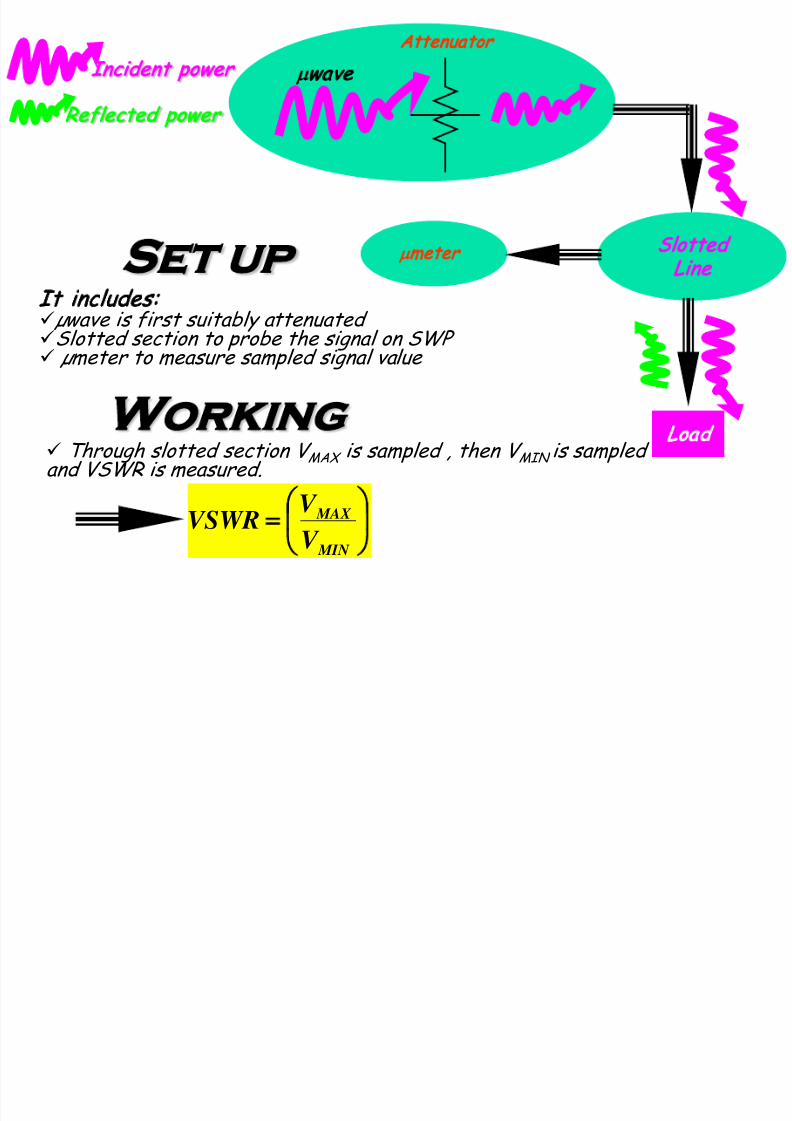
7/23/2019 Microwave Unit 1
http://slidepdf.com/reader/full/microwave-unit-1 130/141
Wavelength
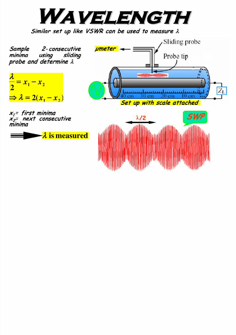
7/23/2019 Microwave Unit 1
http://slidepdf.com/reader/full/microwave-unit-1 131/141
)(22
21
21
x x
x x
−
−
λ
λ
x
1
= first minima
x
2
= next consecutive
minima
Sample 2- consecutive
minima using sliding
probe and determine
λ
Similar set up like VSWR can be used to measure
λ
measuredis
Set up with sca le attached
µmeter
λ/2 SWP

7/23/2019 Microwave Unit 1
http://slidepdf.com/reader/full/microwave-unit-1 132/141

7/23/2019 Microwave Unit 1
http://slidepdf.com/reader/full/microwave-unit-1 133/141
7/23/2019 Microwave Unit 1
http://slidepdf.com/reader/full/microwave-unit-1 134/141
7/23/2019 Microwave Unit 1
http://slidepdf.com/reader/full/microwave-unit-1 135/141
7/23/2019 Microwave Unit 1
http://slidepdf.com/reader/full/microwave-unit-1 136/141
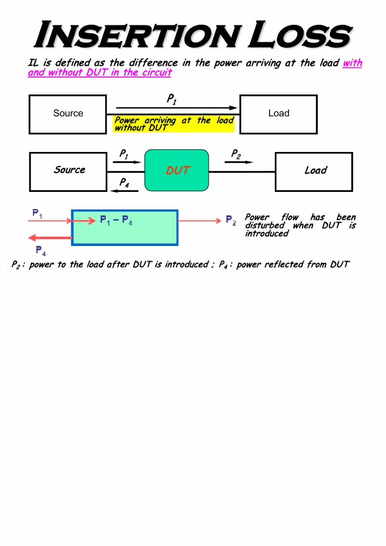
Theory. .
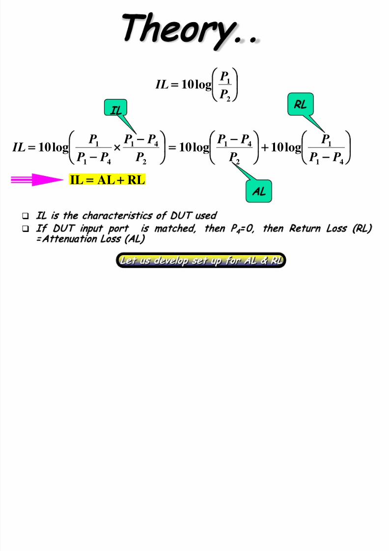
7/23/2019 Microwave Unit 1
http://slidepdf.com/reader/full/microwave-unit-1 137/141
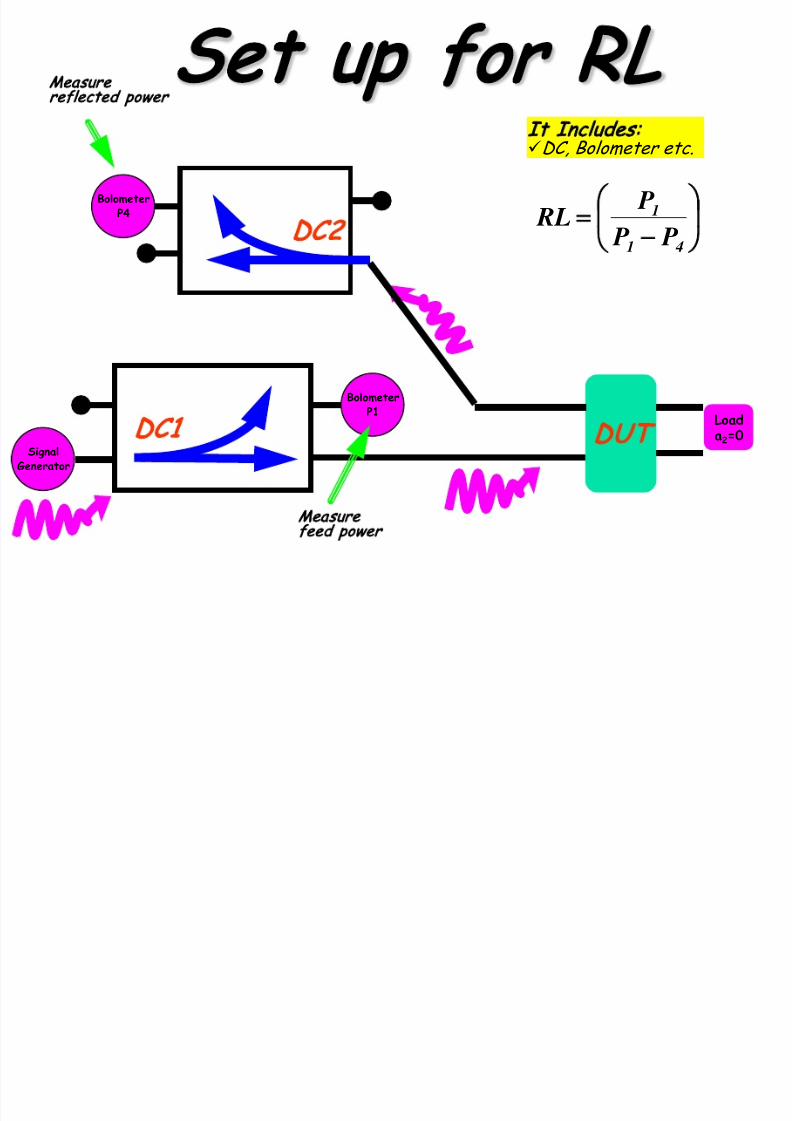
=
2
1log10 P P IL
IL is the characteristics of DUT used
If DUT input port is matched, then P
4
= 0, then Return Loss (RL)
=Attenuation Loss (AL)
−
−
=
−
×
− 41
1
2
41
2
41
41
1 log10log10log10 P P
P
P
P P
P
P P
P P
P IL
IL
RL
AL
Let us develop set up for AL & RL
RLALIL +
Set up for AL
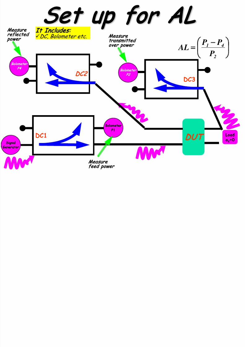
7/23/2019 Microwave Unit 1
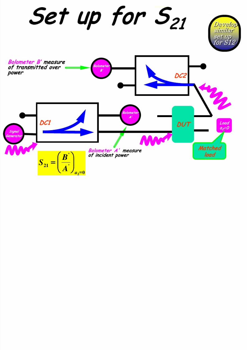
http://slidepdf.com/reader/full/microwave-unit-1 138/141
Loada2=0DC1
DUT
DC3
BolometerP1
SignalGenerator
Bolometer
P2C2
Bolometer
P4
−
= 2
41
P
P P
AL
Measure
feed power
Measure
reflected
power
Measure
transmitted
over power
It Includes:
DC, Bolometer etc.
7/23/2019 Microwave Unit 1
http://slidepdf.com/reader/full/microwave-unit-1 139/141
Concluding Remarks

7/23/2019 Microwave Unit 1
http://slidepdf.com/reader/full/microwave-unit-1 140/141
Fundamentals about µwaves were covered
Various
µ
wave components and their working
were taken up
Set up to measure
µ
wave quantities of
interest were explained
Question?

7/23/2019 Microwave Unit 1
http://slidepdf.com/reader/full/microwave-unit-1 141/141
IRIS
Wave
guide
C L
What is realized by the IRIS arrangement shown? Assume TE
1 , 0
mode