microwave survey report - merced county, ca
TRANSCRIPT
Microwave Path Survey Report
Delta Wireless Incorporated,Merced County Castle Dispatch Hops NA131112‐45773
Release 1.0 December 16, 2013
1

MICROWAVE PATH SURVEY REPORT AVIAT NETWORKS
Issue Releases
Issue Number
Issue Release Date
Changes Preparer
1.0 12/16/2013 Initial Release Rich Weiland
2

MICROWAVE PATH SURVEY REPORT AVIAT NETWORKS
TABLE OF CONTENTS
GENERAL ................................................................................................................................................................................. 4
STATEMENT OF WORK .................................................................................................................................................................... 4 SURVEY PROCEDURES ..................................................................................................................................................................... 4 DESIGN CRITERIA ............................................................................................................................................................................. 4 CLEARANCE CRITERIA ...................................................................................................................................................................... 4 MICROWAVE PATH PERFORMANCE CALCULATIONS AND WARRANTIES ....................................................................................... 5 MICROWAVE FREQUENCY ENGINEERING / INTER‐SYSTEM INTERFERENCE ANALYSIS .................................................................. 5 MICROWAVE FREQUENCY SELECTION ............................................................................................................................................ 5 MICROWAVE FREQUENCY COORDINATION AND FCC LICENSING .................................................................................................. 5 SPECIAL CONSIDERATIONS .............................................................................................................................................................. 5
LIST OF SITES AND PATHS ........................................................................................................................................................ 7
SITES (IN THE ORDER THEY APPEAR IN THIS REPORT): .................................................................................................................................. 7 PATHS (IN THE ORDER THEY APPEAR IN THIS REPORT): ................................................................................................................................ 7
SYSTEM INFORMATION ........................................................................................................................................................... 8
SYSTEM DESCRIPTION ....................................................................................................................................................................... SYSTEM LAYOUT ................................................................................................................................................................................ SYSTEM SPREADSHEET SUMMARY ....................................................................................................................................................
SITE INFORMATION ..................................................................................................................................................................
SITE DESCRIPTION ............................................................................................................................................................................. SITE PHOTOS ..................................................................................................................................................................................... MAP EXTRACTS ..................................................................................................................................................................................
PATH INFORMATION .................................................................................................................................................................
PATH DESCRIPTIONS ......................................................................................................................................................................... PATH CALCULATIONS ........................................................................................................................................................................ PATH PROFILES ..................................................................................................................................................................................
TERMS AND CONDITIONS ..........................................................................................................................................................
3

MICROWAVE PATH SURVEY REPORT AVIAT NETWORKS
GENERAL
STATEMENT OF WORK The following report summarizes the results of a microwave path survey conducted by Aviat Networks, Santa Clara, California, for Delta Wireless Incorporated and Merced County. Field survey work was performed in November 2013, by Rich Weiland. The survey was undertaken to verify site locations and determine antenna sizes and centerlines required to establish a microwave communications system in conformance with customer requirements and current engineering practices.
SURVEY PROCEDURES Preliminary path profiles will be drawn based on the supplied site coordinates and contour information extracted from the best available topographic mapping. A field site survey will be conducted to verify site coordinates and elevations based on North American Datum 1983 (NAD83) and gather information related to the proposed radio equipment and antenna locations, site access, and site development constraints. A field path survey will be conducted to verify path profile elevations, measure all natural and manmade potential obstructions and assess the reflective potential of all natural and manmade surfaces. Antenna centerline heights will be calculated for the proposed frequency band by applying suitable clearance criteria based on the propagation characteristics of the geographic area. Path calculation sheets will then be generated for each hop, based upon the recommended centerline heights. Antenna sizes and the choice of propagation protection diversity will be chosen to meet the required fade margin and the desired path propagation reliability. Propagation outage and reliability calculations will be based on the Vigants model (ref. “Space Diversity Engineering”, BSTJ, 1/75).
DESIGN CRITERIA Path clearance criteria must be established for each path on the basis of total system performance objectives, economic considerations, and careful analysis of local atmospheric conditions derived from published climatological data, where available, and reported microwave transmission experience pertinent to the area. Antenna heights much greater than actually needed cause an unwarranted increase in system cost, and on paths with significant ground reflections, it can increase the exposure to multipath and ground reflection signal fading. It is desirable to locate the antennas high enough so that even under severe super-standard atmospheric refractive conditions (surface ducting) there is adequate clearance such that signal entrapment does not significantly degrade the fade margin of the path or generate excessive multipath fade activity. The choice of clearance criteria for a microwave path is a balance between cost and performance. The path clearance criterion as applied to a given geographic area is a function of the degree and direction of atmospheric beam bending and can conveniently be defined by the equivalent earth radius K factor:
RadiussEarthActual
RadiussEarthEffectiveK
'
'
The Median Propagation value of K = 4/3 allows the normal microwave horizon to be slightly extended when compared to the optical horizon; however, under certain meteorological conditions (for example, during nighttime super-refractivity usually associated with temperature inversions) the value of K increases to 2 or greater for periods of several minutes to several hours. This increases the path clearance and results in the heavy multipath fade activity seen on some reflective paths and antenna decoupling power fading on others.
CLEARANCE CRITERIA The criteria used to design a radio path in this region are the greater of:
Main to Main: o 100% first Fresnel zone radius over K=4/3, or o 60% first Fresnel zone radius over K=1
4

MICROWAVE PATH SURVEY REPORT AVIAT NETWORKS
Main to Diversity:
o 60% first Fresnel zone radius over K=4/3 (Not Applicable)
MICROWAVE PATH PERFORMANCE CALCULATIONS AND WARRANTIES The microwave path design models most frequently employed within the industry (e.g., Vigants, and ITU PN-530) provide a reasonably accurate (and therefore usually guaranteed) estimate of the cumulative time a path will be out of service due to random atmospheric multipath fading under normal atmospheric conditions. These models do not (and cannot) accommodate abnormal, unusual, anomalous, or otherwise unpredictable conditions of weather or atmospheric refractivity.
MICROWAVE FREQUENCY ENGINEERING / INTER-SYSTEM INTERFERENCE ANALYSIS Aviat Networks will partner with Comsearch, a CommScope company, to provide cost-effective frequency planning and FCC licensing services for radio communications systems (if required). The planning software used, considers specific operating parameters of both the proposed microwave system and the environment microwave systems (license and proposed) to properly consider the interference potential of the new path or system. Parameters and data elements incorporated into the modeling include, but are not limited to, antenna type, antenna height, elevation, antenna radiation pattern, receiver filter performance, terrain, radio modulation, path orientation, receiver threshold, etc. These elements are required to accurately predict specific interfering levels into and from the existing microwave systems. The accuracy of the calculations is ensured by “real time” maintenance of the Comsearch point-to-point microwave, earth station, radio equipment, antenna, interference objective, and contact database.
MICROWAVE FREQUENCY SELECTION The interference analysis performed on the microwave system identifies available frequencies considering existing and proposed systems found in the Comsearch database. When applicable, an analysis of the systems in the adjacent bands can be done to ensure the microwave system does not receive unwanted threshold degradation. In bands shared with satellite systems, an analysis of potential interference with earth stations and with the geo-stationary satellite orbit can also be done. Additionally, co-located or nearby transmitters already licensed in the required frequency band can be identified in order to reduce the possibility of “bucking” an existing high/low frequency plan that could increase the possibility of receiver overload or reflective interference from a nearby system.
MICROWAVE FREQUENCY COORDINATION AND FCC LICENSING The majority of microwave bands subject to FCC Rule Part 101 require prior coordination with existing licensees. Aviat Networks will partner with Comsearch to perform the frequency coordination and FCC licensing on behalf of the customer (if required). The procedure will include notification of the technical parameters of the proposed system to all existing and proposed licensees in the area and frequency band of operation. Frequency coordination will also be performed with Canadian and Mexican authorities in border areas when necessary. By FCC rule, recipients are given 30 days to respond, or in some cases an expedited response can be requested. Upon completion of the prior coordination process, documentation required to satisfy FCC Rule Part 101.103 (d) can be prepared on behalf of the customer. This will include any necessary exhibits, including Supplemental Showings required upon submittal of the requested license application. The FCC filing process includes:
Filing of the FCC Form 601 microwave application upon written approval from the customer and providing an electronic copy of the application to the customer via email.
Tracking the status of the application until the license is granted by the FCC. Amendments will be handled expeditiously on behalf of the customer for any questions or concerns from the Commission.
Notification to the licensee via email when the license is granted by the FCC. Filing of the required “Completion of Construction” notification with the FCC upon written approval from the
licensee and notification of the filing via email.
SPECIAL CONSIDERATIONS On all microwave radio paths traversing urban areas there exists the possibility of multiple on- and off-path structural reflections which generate long-delayed echoes, as well as “terrain scatter” RF intra- and inter-system interference. Long delayed, low-level echoes have no effect on digital radio performance; however, the terrain scatter mechanism cannot be accurately predicted nor precisely measured without an extensive and expensive field trial. Consequently,
5
MICROWAVE PATH SURVEY REPORT AVIAT NETWORKS
this mechanism is specifically excluded from all current industry-wide path survey and frequency coordination performance guarantees. The structure supporting the microwave antenna can take many forms. The antenna is most often mounted on a tower, but can be mounted on a variety of structures such as roof tripods, penthouse wall, wooden telephone pole or metal monopole. It is recommended that the customer or end user conduct a structural analysis of the support structure to determine if the structure will support the additional loading imposed by the antenna and its mount. The structure must also meet the twist and sway requirements per EIA/ANSI 222G. Certain geographic areas / frequency bands are restricted due to Radio Astronomy use or DOD and other Government top-secret installations. Even outside the absolute exclusion zone, there are areas where 18 GHz can be cleared by DOD. Coordinators must file applications and wait for the FCC to contact NTIA and NTIA to contact IRAC to analyze these before FCC licenses are granted. If the application is rejected, the proposed microwave link could be subject to redesign with another frequency band.
6
MICROWAVE PATH SURVEY REPORT AVIAT NETWORKS
LIST OF SITES AND PATHS
SITES (in the order they appear in this report):
Castle Dispatch Mt. Bullion Pacheco
PATHS (in the order they appear in this report):
Castle Dispatch – Mt. Bullion Castle Dispatch – Pacheco
7

MICROWAVE PATH SURVEY REPORT AVIAT NETWORKS
SYSTEM INFORMATION
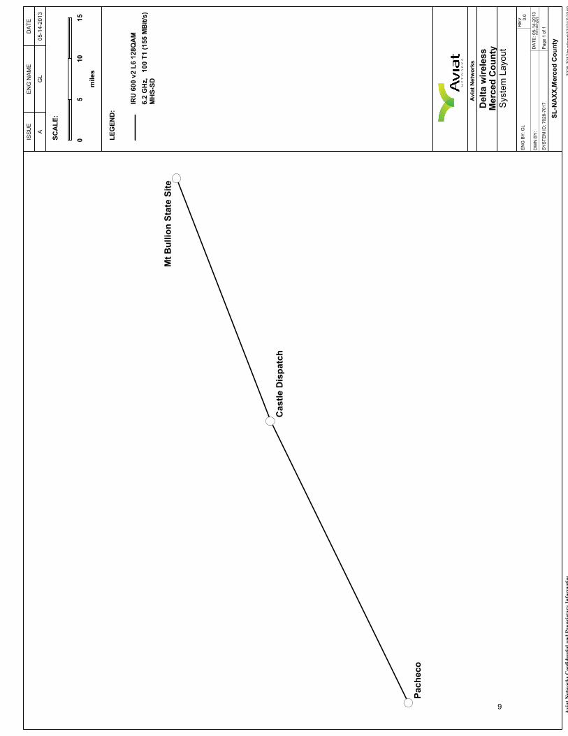
SYSTEM DESCRIPTION Merced County is adding a new node to its microwave network, to add a new dispatch center, Castle Dispatch. Two new microwave hops will be installed to provide connectivity to it.
8
7028-7017/rweiland/131217:2249
Aviat Networks Confidential and Proprietary Information
Pacheco
Mt Bullion State Site
Castle Dispatch
ISSUE
ENG NAME
DATE
AGL
05-14-2013
Aviat Networks
Delta wireless
Merced County
System Layout
ENG BY: GL
REV 0.0
DWN BY:
DATE: 05-14-2013
mm-dd-yyyy
SYSTEM ID: 7028-7017
Page 1 of 1
SCALE:
LEGEND:
05
10
15
miles
SL-NAXX,Merced County
IRU 600 v2 L6 128QAM
6.2 GHz, 100 T1 (155 MBit/s)
MHS-SD
9

Topo USA® 6.0
Data use subject to license.
© 2006 DeLorme. Topo USA® 6.0.
www.delorme.com
TN
MN (13.5°E)
0 4 8 12 16 20
0 6 12 18 24 30
mikm
Scale 1 : 700,000
1" = 11.05 mi Data Zoom 8-210

7028-7017/rweiland/131217:2248
Aviat Networks Confidential and Proprietary Information
Aviat Networks
Aviat Networks
Delta wireless
Microwave System Summary
17-Dec-2013 / Sheet 1 of 1
TRANSMIT SITE NAME
CORRESPONDING
PATH I.D.
DISTANCE
PRIMARY
DIVERSITYDOME
PRIMARY
DIVERSITY
RADIO TYPE
CAP
XMIT
RSL
SLOPE
TRANSMIT
COMMON
RECEIVE SITE
ANTENNA
ANTENNA
TRANS
TRANS
PWR
TOP OF
EQUALIZERONLY PAD
PAD
COORDINATES
AZIMUTH
SIZE /
SIZE /
LINE
LINE
CONFIGURATION
(dBm)
RACK
TRUE
HEIGHT
HEIGHT
LENGTH
LENGTH
(dBm)
ELEVATION (ft)
(ft)
(ft)
(ft)
(ft)
NORTH
FREQ (GHz)
Castle Dispatch
LAT: 37 - 22 - 8.4
LON: 120 - 34 - 12.6
ELEV: 172.0
Pacheco
DWMC-1
38.35 mi
6.0 / 120.0
4 / 80
244.14°
___
180.0
140.0
IRU 600 v2 L6
128QAM
MHS-SD
6.175
100 T1 (155 MBit/s)
30.5
-41.2
STD
___
___
Mt Bullion State SiteDWMC-2
31.80 mi
6.0 / 135.0
4 / 95
68.80°
___
195.0
155.0
IRU 600 v2 L6
128QAM
MHS-SD
6.175
100 T1 (155 MBit/s)
30.5
-40.2
STD
___
___
Mt Bullion State Site
LAT: 37 - 32 - 4.3
LON: 120 - 1 - 49.1
ELEV: 4252.0
Castle Dispatch
DWMC-2
31.80 mi
6.0 / 75.0
4 / 35
249.13°
___
195.0
155.0
IRU 600 v2 L6
128QAM
MHS-SD
6.175
100 T1 (155 MBit/s)
30.5
-40.2
STD
___
___
Pacheco
LAT: 37 - 7 - 29.0
LON: 121 - 11 - 42.6
ELEV: 2355.0
Castle Dispatch
DWMC-1
38.35 mi
6.0 / 85.0
4 / 45
63.76°
___
150.0
110.0
IRU 600 v2 L6
128QAM
MHS-SD
6.175
100 T1 (155 MBit/s)
30.5
-41.2
STD
___
___
11
MICROWAVE PATH SURVEY REPORT AVIAT NETWORKS
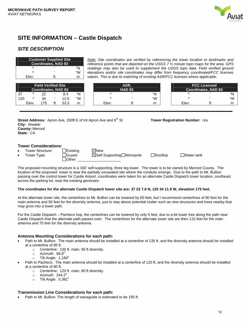
SITE INFORMATION – Castle Dispatch
SITE DESCRIPTION Note: Site coordinates are verified by referencing the tower location to landmarks and reference points that are depicted on the USGS 7 ½ minute topo maps for the area. GPS readings may also be used to supplement the USGS topo data. Field verified ground elevations and/or site coordinates may differ from frequency coordinated/FCC licenses values. This is due to matching of existing ASR/FCC licenses where applicable.
Field Verified Site Coordinates, NAD 83
ASR, NAD 83
FCC Licensed Coordinates, NAD 83
37 º 22 ‘ 8.4 “N º ‘ “N º ‘ “N 120 º 34 ‘ 12.6 “W º ‘ “W º ‘ “W
Elev: 175 ft 53.3 m Elev: ft m Elev: ft m Street Address: Apron Ave, 200ft E of Int Apron Ave and 6th St Tower Registration Number: n/a City: Atwater County: Merced State: CA Tower Considerations: Tower Structure: Existing New Tower Type: Guyed Self Supporting Monopole Rooftop Water tank
Other: _____________________
The proposed mounting structure is a 160’ self-supporting, three leg tower. The tower is to be owned by Merced County. The location of the proposed tower is near the partially excavated site where the conduits emerge. Due to the path to Mt. Bullion passing over the control tower for Castle Airport, coordinates were taken for an alternate Castle Dispatch tower location, southeast across the parking lot, near the existing generator. The coordinates for the alternate Castle Dispatch tower site are: 37 22 7.6 N, 120 34 11.9 W, elevation 175 feet. At the alternate tower site, the centerlines to Mt. Bullion can be lowered by 60 feet, but I recommend centerlines of 90 feet for the main antenna and 50 feet for the diversity antenna, just to stay above potential clutter such as new structures and trees nearby that may grow into a lower path. For the Castle Dispatch – Pacheco hop, the centerlines can be lowered by only 5 feet, due to a bit lower tree along the path near Castle Dispatch that the alternate path passes over. The centerlines for the alternate tower site are then 115 feet for the main antenna and 75 feet for the diversity antenna. Antenna Mounting Considerations for each path: Path to Mt. Bullion: The main antenna should be installed at a centerline of 135 ft, and the diversity antenna should be installed
at a centerline of 95 ft. o Centerline: 135 ft. main, 95 ft diversity. o Azimuth: 68.8o o Tilt Angle: 1.184o
Path to Pacheco: The main antenna should be installed at a centerline of 120 ft, and the diversity antenna should be installed at a centerline of 80 ft.
o Centerline: 120 ft. main, 80 ft diversity. o Azimuth: 244.2o o Tilt Angle: 0.381o
Transmission Line Considerations for each path: Path to Mt. Bullion: The length of waveguide is estimated to be 195 ft.
Customer Supplied Site Coordinates, NAD 83
º ‘ “N º ‘ “W
Elev: ft m
12

MICROWAVE PATH SURVEY REPORT AVIAT NETWORKS
Path to Pacheco: The length of waveguide is estimated to be 180 ft. Cable Ladder: Use Existing Recommended Not Required Cable Bridge: Use Existing Recommended Not Required Ice Bridge: Use Existing Recommended Not Required Entry Ports: Use Existing New Entry Port Required Ground Bus Bar: Use Existing New Bus Bar Required Site Access Considerations: Locked gate to parking lot where planned tower is to be located.
13

Topo USA® 6.0
Data use subject to license.
© 2006 DeLorme. Topo USA® 6.0.
www.delorme.com
TN
MN (13.5°E)
0 200 400 600 800 1000
0 100 200 300 400 500
ftm
Scale 1 : 12,800
1" = 1,066.7 ft Data Zoom 14-014
MICROWAVE PATH SURVEY REPORT AVIAT NETWORKS
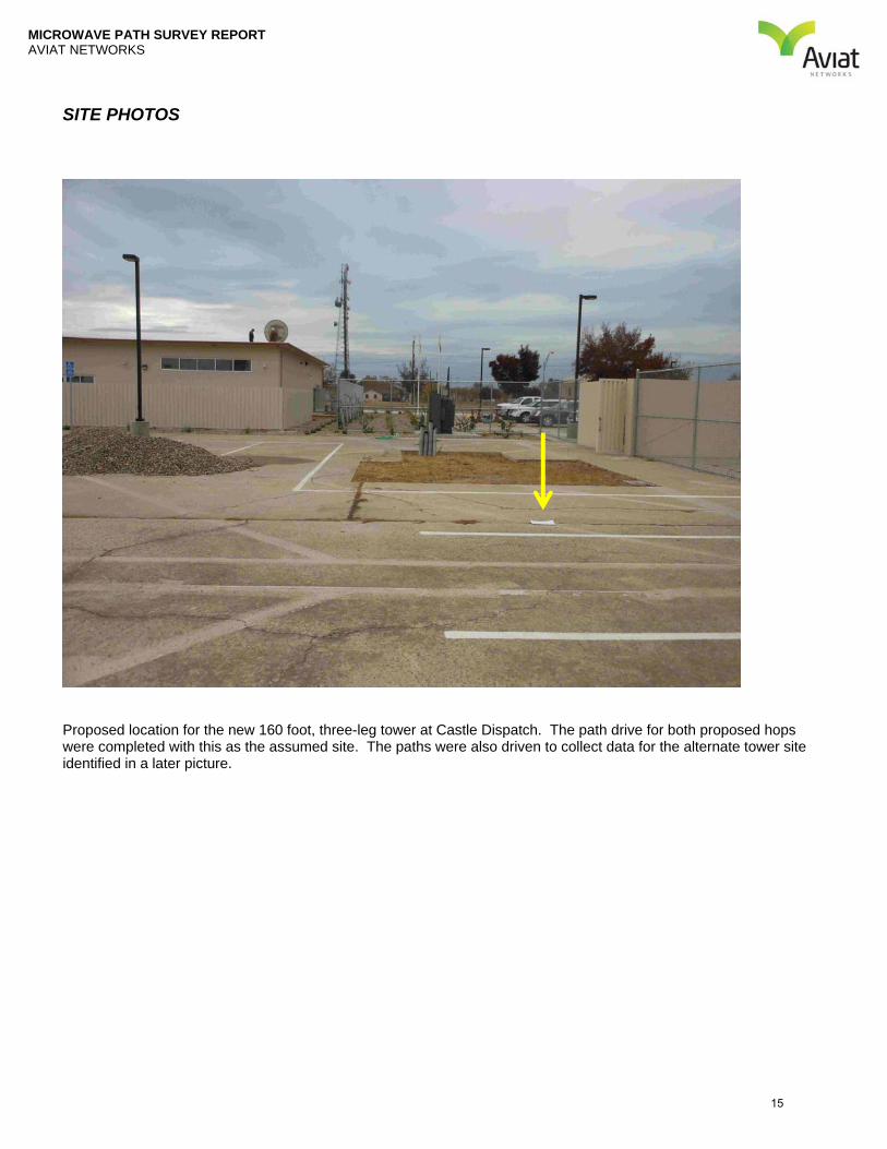
SITE PHOTOS
Proposed location for the new 160 foot, three-leg tower at Castle Dispatch. The path drive for both proposed hops were completed with this as the assumed site. The paths were also driven to collect data for the alternate tower site identified in a later picture.
15

MICROWAVE PATH SURVEY REPORT AVIAT NETWORKS
Another view of the proposed tower location.
16

MICROWAVE PATH SURVEY REPORT AVIAT NETWORKS
View toward Mt. Bullion from ground level. The path from the proposed tower location passes over the airport control tower.
17

MICROWAVE PATH SURVEY REPORT AVIAT NETWORKS
View toward Pacheco from ground level.
18
MICROWAVE PATH SURVEY REPORT AVIAT NETWORKS
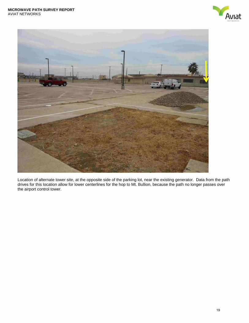
Location of alternate tower site, at the opposite side of the parking lot, near the existing generator. Data from the path drives for this location allow for lower centerlines for the hop to Mt. Bullion, because the path no longer passes over the airport control tower.
19

MICROWAVE PATH SURVEY REPORT AVIAT NETWORKS
SITE INFORMATION – Mt. Bullion
SITE DESCRIPTION Note: Site coordinates are verified by referencing the tower location to landmarks and reference points that are depicted on the USGS 7 ½ minute topo maps for the area. GPS readings may also be used to supplement the USGS topo data. Field verified ground elevations and/or site coordinates may differ from frequency coordinated/FCC licenses values. This is due to matching of existing ASR/FCC licenses where applicable.
Field Verified Site Coordinates, NAD 83
ASR, NAD 83
FCC Licensed Coordinates, NAD 83
37 º 32 ‘ 4.3 “N º ‘ “N º ‘ “N 120 º 01 ‘ 49.1 “W º ‘ “W º ‘ “W
Elev: 4250 ft 1294 m Elev: ft m Elev: ft m Street Address: Atop Mount Bullion Tower Registration Number: n/a City: Mariposa County: Mariposa State: CA Tower Considerations: Tower Structure: Existing New Tower Type: Guyed Self Supporting Monopole Rooftop Water tank
Other: _____________________
The mounting structure is a 160’ self-supporting tower. The four-leg tower is under construction, with 120 feet of structure completed, and two, 20-foot monopole-type sections to be stacked on top. The tower is owned by the State of California. Antenna Mounting Considerations for each path: Path to Castle Dispatch: The main antenna should be installed at a centerline of 75 ft on the southwest leg of the tower, and
the diversity antenna should be mounted at a centerline of 35 feet.. o Centerline: 75 ft for the main antenna, and 35 ft for the diversity. o Azimuth: 249.1o o Tilt Angle: -1.56o
Transmission Line Considerations for each path: Path to Castle Dispatch: The length of waveguide is estimated to be 195 ft. Cable Ladder: Use Existing Recommended Not Required Cable Bridge: Use Existing Recommended Not Required Ice Bridge: Use Existing Recommended Not Required Entry Ports: Use Existing New Entry Port Required Ground Bus Bar: Use Existing New Bus Bar Required Site Access Considerations: none
Customer Supplied Site Coordinates, NAD 83
º ‘ “N º ‘ “W
Elev: ft m
20
Topo USA® 6.0
Data use subject to license.
© 2006 DeLorme. Topo USA® 6.0.
www.delorme.com
TN
MN (13.5°E)
0 600 1200 1800 2400 3000
0 200 400 600 800 1000
ftm
Scale 1 : 25,000
1" = 2,083.3 ft Data Zoom 13-021

MICROWAVE PATH SURVEY REPORT AVIAT NETWORKS
SITE PHOTOS
View of Mt. Bullion with location of proposed antennas toward Castle Dispatch shown.
To Castle Dispatch, mount main antenna at 75 ft, azimuth 249.1o, tilt -1.56o, on the southwest tower leg.
To Castle Dispatch, mount diversity antenna at 35 ft, azimuth 249.1o, tilt -1.56o, on the southwest tower leg.
22
MICROWAVE PATH SURVEY REPORT AVIAT NETWORKS
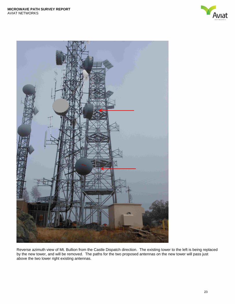
Reverse azimuth view of Mt. Bullion from the Castle Dispatch direction. The existing tower to the left is being replaced by the new tower, and will be removed. The paths for the two proposed antennas on the new tower will pass just above the two lower right existing antennas.
23

MICROWAVE PATH SURVEY REPORT AVIAT NETWORKS
View toward Castle Dispatch from ground level.
24
MICROWAVE PATH SURVEY REPORT AVIAT NETWORKS
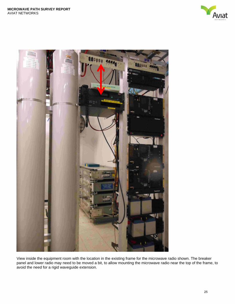
View inside the equipment room with the location in the existing frame for the microwave radio shown. The breaker panel and lower radio may need to be moved a bit, to allow mounting the microwave radio near the top of the frame, to avoid the need for a rigid waveguide extension.
25

MICROWAVE PATH SURVEY REPORT AVIAT NETWORKS
Proposed route for waveguide.
26
MICROWAVE PATH SURVEY REPORT AVIAT NETWORKS
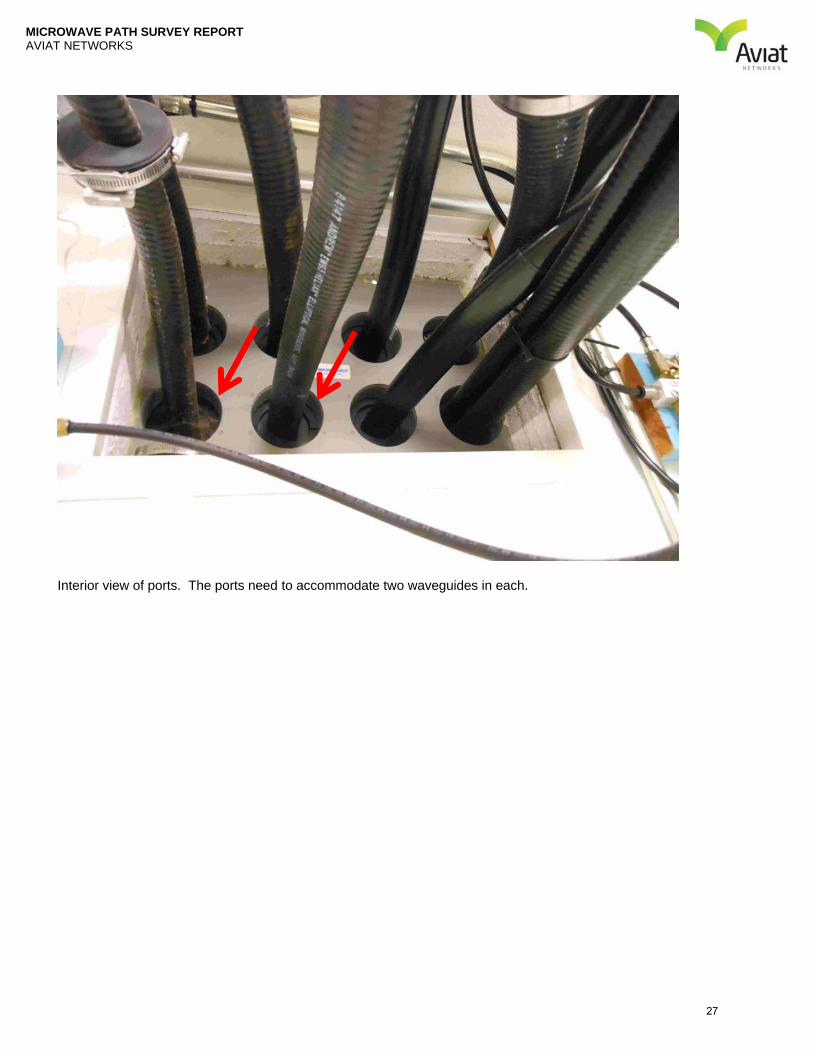
Interior view of ports. The ports need to accommodate two waveguides in each.
27

MICROWAVE PATH SURVEY REPORT AVIAT NETWORKS
Exterior view of ports.
28
MICROWAVE PATH SURVEY REPORT AVIAT NETWORKS
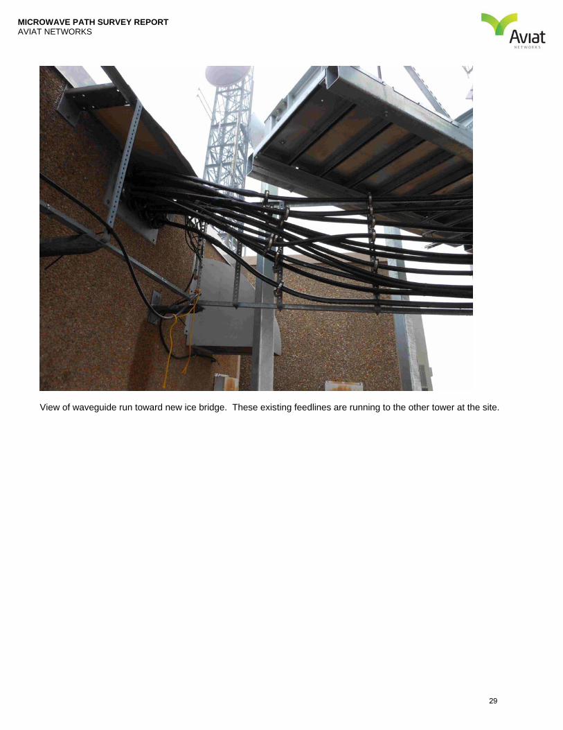
View of waveguide run toward new ice bridge. These existing feedlines are running to the other tower at the site.
29

MICROWAVE PATH SURVEY REPORT AVIAT NETWORKS
View of new ice bridge.
30
MICROWAVE PATH SURVEY REPORT AVIAT NETWORKS
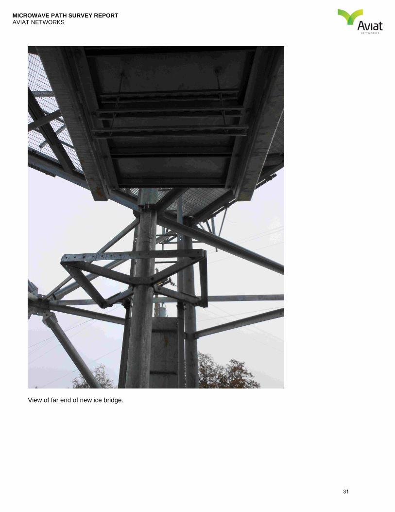
View of far end of new ice bridge.
31

MICROWAVE PATH SURVEY REPORT AVIAT NETWORKS
View of end of ice bridge and cable ladder up tower.
32

MICROWAVE PATH SURVEY REPORT AVIAT NETWORKS
Cable ladder up tower.
33

MICROWAVE PATH SURVEY REPORT AVIAT NETWORKS
SITE INFORMATION – Pacheco
SITE DESCRIPTION Note: Site coordinates are verified by referencing the tower location to landmarks and reference points that are depicted on the USGS 7 ½ minute topo maps for the area. GPS readings may also be used to supplement the USGS topo data. Field verified ground elevations and/or site coordinates may differ from frequency coordinated/FCC licenses values. This is due to matching of existing ASR/FCC licenses where applicable.
Field Verified Site Coordinates, NAD 83
ASR, NAD 83
FCC Licensed Coordinates, NAD 83
37 º 07 ‘ 29.1 “N 37 º 07 ‘ 29.2 “N º ‘ “N 121 º 11 ‘ 42.7 “W 121 º 11 ‘ 42.2 “W º ‘ “W
Elev: 2380 ft 724 m Elev: 2380 ft 724 m Elev: ft m Street Address: Pacheco Pass Tower Registration Number: 1274185 City: Santa Nella County: Merced State: CA Tower Considerations: Tower Structure: Existing New Tower Type: Guyed Self Supporting Monopole Rooftop Water tank
Other: _____________________
The mounting structure is a four-leg, self-supporting tower, Three, 20-foot tower extension sections are to be added to the existing tower, for a total height of 130 feet. The steel for the extension is on the ground in the compound. The tower is owned by David Field. Antenna Mounting Considerations for each path: Path to Castle Dispatch: The main antenna should be installed at a centerline of 85 ft on the southeast leg of the tower, and
the diversity antenna should be mounted at a centerline of 45 feet..
o Centerline: 85ft. for the main antenna, and 45 ft. for the diversity. o Azimuth: 63.8o o Tilt Angle: -0.834o
Transmission Line Considerations for each path: Path to Castle Dispatch: The length of waveguide is estimated to be 150 ft.
Cable Ladder: Use Existing Recommended Not Required Cable Bridge: Use Existing Recommended Not Required Ice Bridge: Use Existing Recommended Not Required Entry Ports: Use Existing New Entry Port Required Ground Bus Bar: Use Existing New Bus Bar Required Site Access Considerations: Locked gate.
Customer Supplied Site Coordinates, NAD 83
º ‘ “N º ‘ “W
Elev: ft m
34
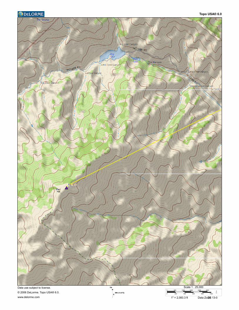
Topo USA® 6.0
Data use subject to license.
© 2006 DeLorme. Topo USA® 6.0.
www.delorme.com
TN
MN (13.6°E)
0 600 1200 1800 2400 3000
0 200 400 600 800 1000
ftm
Scale 1 : 25,000
1" = 2,083.3 ft Data Zoom 13-035
MICROWAVE PATH SURVEY REPORT AVIAT NETWORKS
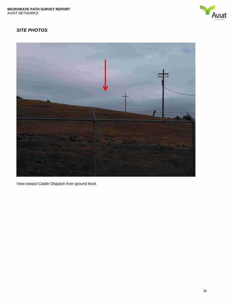
SITE PHOTOS
View toward Castle Dispatch from ground level.
36
MICROWAVE PATH SURVEY REPORT AVIAT NETWORKS
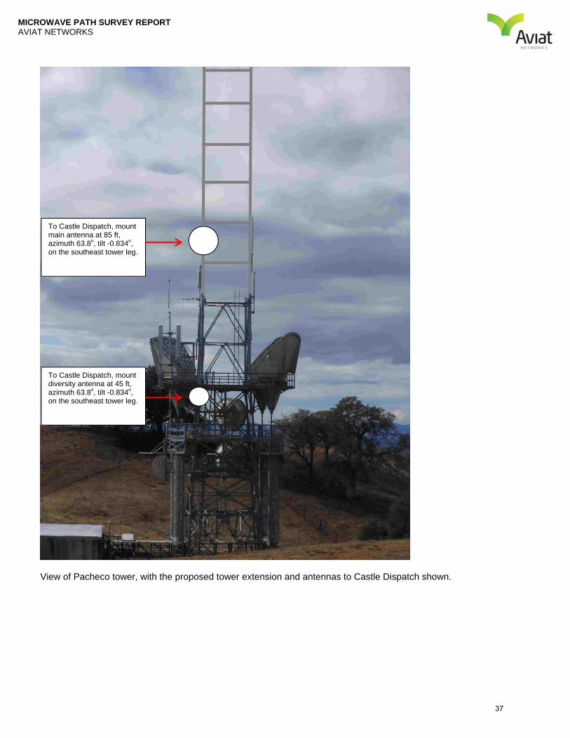
View of Pacheco tower, with the proposed tower extension and antennas to Castle Dispatch shown.
To Castle Dispatch, mount main antenna at 85 ft, azimuth 63.8o, tilt -0.834o, on the southeast tower leg.
To Castle Dispatch, mount diversity antenna at 45 ft, azimuth 63.8o, tilt -0.834o, on the southeast tower leg.
37
MICROWAVE PATH SURVEY REPORT AVIAT NETWORKS
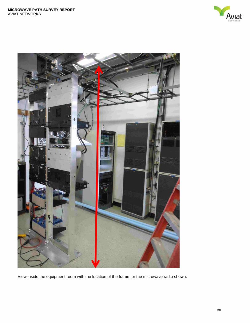
View inside the equipment room with the location of the frame for the microwave radio shown.
38

MICROWAVE PATH SURVEY REPORT AVIAT NETWORKS
Proposed route for waveguide.
39

MICROWAVE PATH SURVEY REPORT AVIAT NETWORKS
Interior view of ports and ground block.
40
MICROWAVE PATH SURVEY REPORT AVIAT NETWORKS
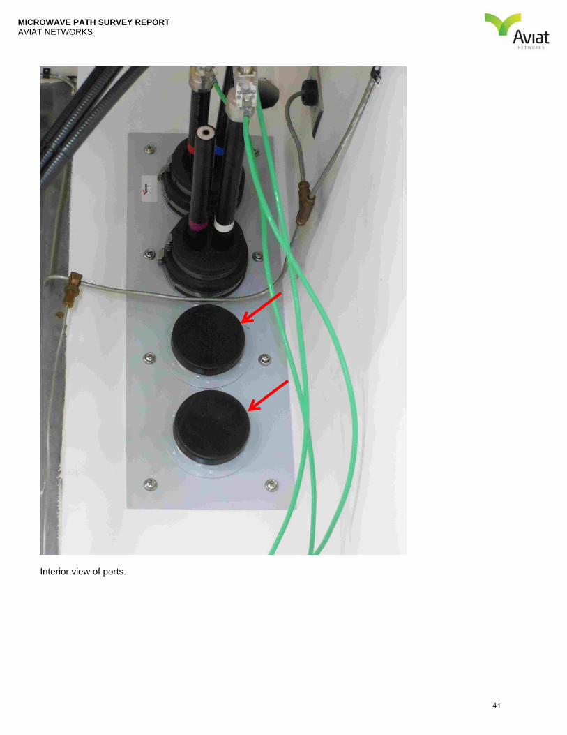
Interior view of ports.
41

MICROWAVE PATH SURVEY REPORT AVIAT NETWORKS
Exterior view of ports.
42

MICROWAVE PATH SURVEY REPORT AVIAT NETWORKS
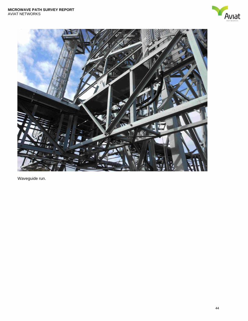
Waveguide run.
43
MICROWAVE PATH SURVEY REPORT AVIAT NETWORKS
Waveguide run.
44
MICROWAVE PATH SURVEY REPORT AVIAT NETWORKS
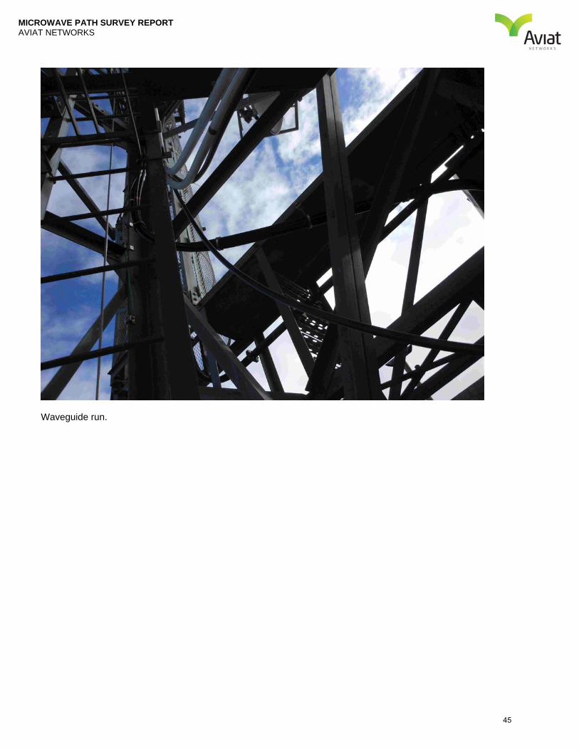
Waveguide run.
45
MICROWAVE PATH SURVEY REPORT AVIAT NETWORKS
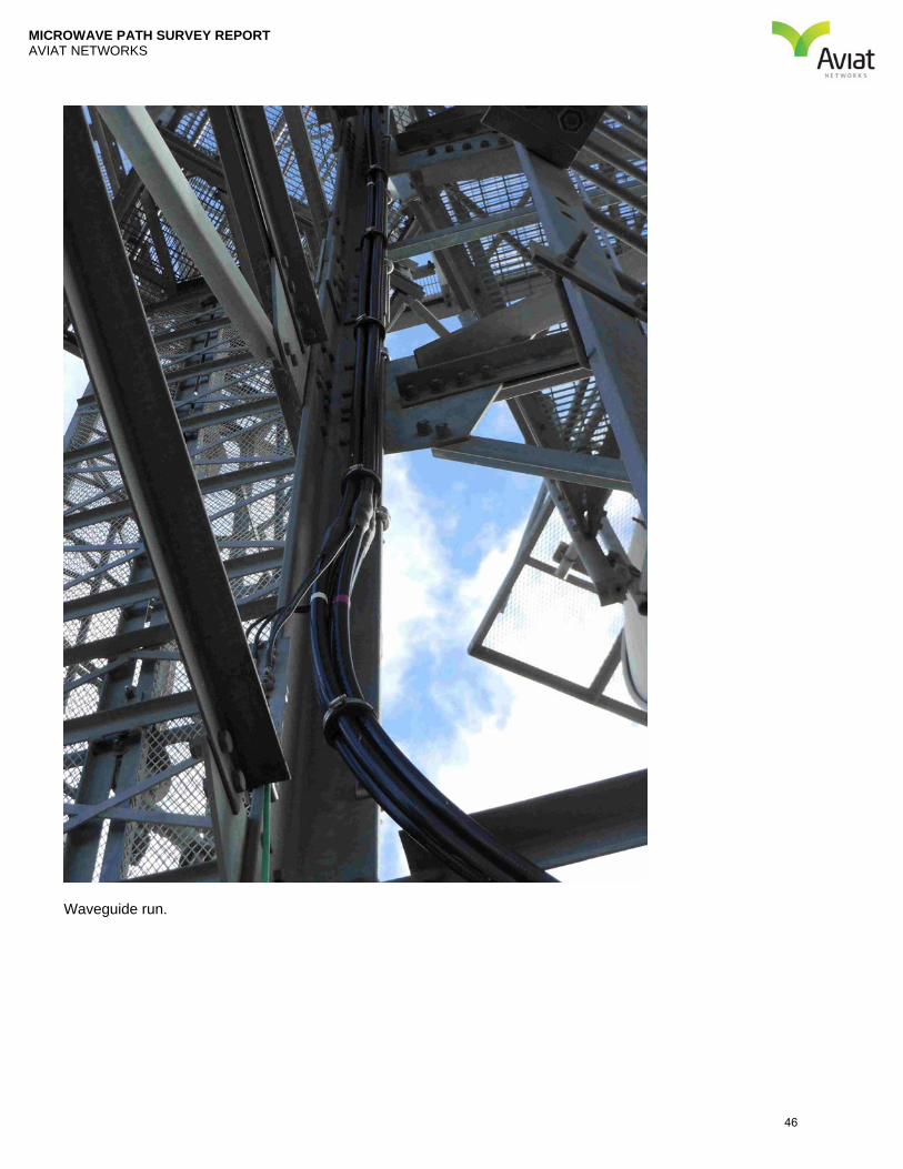
Waveguide run.
46
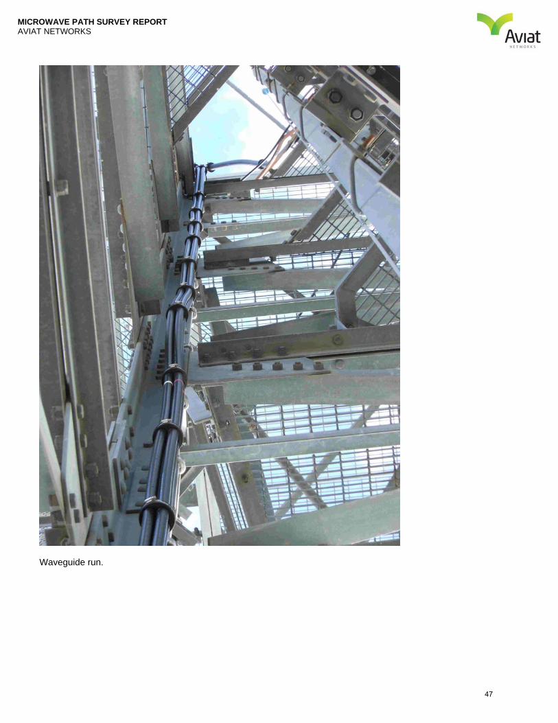
MICROWAVE PATH SURVEY REPORT AVIAT NETWORKS
Waveguide run.
47

MICROWAVE PATH SURVEY REPORT AVIAT NETWORKS
PATH INFORMATION: Castle Dispatch – Mt. Bullion
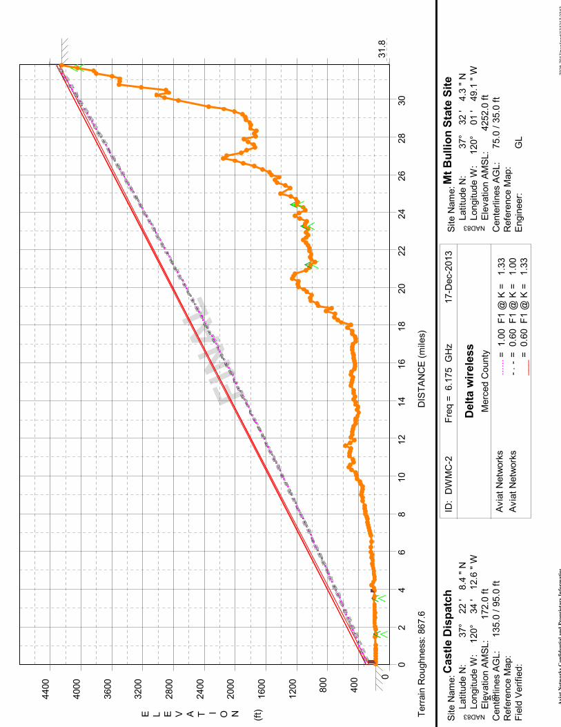
PATH DESCRIPTION Path Length: 31.8 Miles Frequency Band: 6 GHz General Path Description: Path Description: This is a long path, with a difference of over 4000 ft in elevation between the sites. The control point along this path is a building 900 feet from the proposed Castle Dispatch tower site, the 98 foot tall control tower for the Castle Airport. The vegetation along this path is a mix of tree types, of heights between 20 and 75 ft. A tree growth factor of 10 ft was added to accommodate expected future growth. Path Climate Considerations: Heightened humidity gradients provide additional signal paths through the atmosphere between radio sites which result in varying degrees of composite destructive and sometimes constructive interference at the receiving antenna. Space diversity is successfully deployed as a countermeasure against this atmospheric, refractive multi-path fading phenomenon but it does not provide much mitigation against harsher phenomenon that also occur in this region such as beam spreading, blackout fading/ducting and antenna decoupling, the latter of which is due to elevated incident signal arrival angle due to very high K factor path trajectory refractive bending. There are a number of design approaches that can help mitigate these harsher effects. One is to simply deploy relatively short path lengths. The effects are still there but they’re reduced to a manageable level. The second is to deploy ‘high-low’ path trajectories with a minimum of 6 milliradians (roughly ½ degree) of inclination angle. This path has an inclination angle of about 1.2 degrees, and should perform well.
48
7028-7
017/rw
eila
nd/1
31217:2
343
Aviat Networks Confidential and Proprietary Information
FINAL
0
400
800
1200
1600
2000
2400
2800
3200
3600
4000
4400
02
46
810
12
14
16
18
20
22
24
26
28
30
31.8
E L E V A T I O N (ft)
DIS
TAN
CE (m
iles)
Terrain
Roughness: 867.6
Castle Dispatch
Mt Bullion State Site
NAD83
NAD83
Site N
am
e:
Latitu
de N
:
Longitude W
:
Ele
vation A
MSL:
Cente
rlin
es A
GL:
Refe
rence M
ap:
Fie
ld V
erified:
Site N
am
e:
Latitu
de N
:
Longitude W
:
Ele
vation A
MSL:
Cente
rlin
es A
GL:
Refe
rence M
ap:
Engin
eer:
ID:
DW
MC
-2Fre
q =
6.1
75 G
Hz
17-D
ec-2
013
Delta wireless
Avia
t N
etw
ork
s
Avia
t N
etw
ork
s
Merc
ed C
ounty = 1.0
0 F1 @
K =
1
.33
......
= 0.6
0 F1 @
K =
1
.00
- -
.
= 0.6
0 F1 @
K =
1
.33
___
135.0
/ 9
5.0
ft
75.0
/ 3
5.0
ft
GL
37°
22 '
8.4
" N
120°
34 '
12.6
" W
37°
32 '
4.3
" N
120°
01 '
49.1
" W
172.0
ft
4252.0
ft
49
7028-7017/rweiland/131217:2342Aviat Networks Confidential and Proprietary Information
Aviat Networks
Aviat Networks
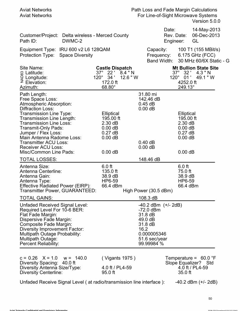
Path Loss and Fade Margin Calculations
For Line-of-Sight Microwave Systems
Version 5.0.0
Date: 14-May-2013
Customer/Project: Delta wireless - Merced County Rev. Date: 06-Dec-2013
Path ID: DWMC-2 Engineer: GL
Equipment Type: IRU 600 v2 L6 128QAM Capacity: 100 T1 (155 MBit/s)
Protection Type: Space Diversity Frequency: 6.175 GHz (FCC)
Band Width: 30 MHz 60/6X Static - G
Site Name: Castle Dispatch Mt Bullion State Site
NAD83 Latitude:
Longitude:37° 22 ' 8.4 " N 37° 32 ' 4.3 " N
120° 34 ' 12.6 " W 120° 01 ' 49.1 " WElevation: 172.0 ft 4252.0 ft
Azimuth: 68.80° 249.13°
Path Length: 31.80 miFree Space Loss: 142.46 dBAtmospheric Absorption: 0.45 dBDiffraction Loss: 0.00 dBTransmission Line Type: Elliptical EllipticalTransmission Line Length: 195.00 ft 195.00 ftTransmission Line Loss: 2.30 dB 2.30 dBTransmit-Only Pads: 0.00 dB 0.00 dBJumper / Flex Loss: 0.27 dB 0.27 dBMain Antenna Radome Loss: 0.00 dB 0.00 dBTransmitter ACU Loss: 0.40 dBReceiver ACU Loss: 0.00 dBMisc/Common Line Pads: 0.00 dB 0.00 dB
TOTAL LOSSES: 148.46 dB
Antenna Size: 6.0 ft 6.0 ftAntenna Centerline: 135.0 ft 75.0 ftAntenna Gain: 38.9 dB 38.9 dBAntenna Type: HP6-59 HP6-59Effective Radiated Power (EIRP): 66.4 dBm 66.4 dBmTransmitter Power, GUARANTEED: High Power (30.5 dBm)
TOTAL GAINS: 108.3 dB
Unfaded Received Signal Level: -40.2 dBm (+/- 2dB)Required Level For 10-6 BER: -72.0 dBmFlat Fade Margin: 31.8 dBDispersive Fade Margin: 49.0 dBComposite Fade Margin: 31.8 dBDiversity Improvement Factor: 16.2Multipath Outage Probability: 0.000005346Multipath Outage: 51.6 sec/yearPercent Reliability: 99.99984 %
c = X = w =0.26 1.0 140.0 ( Vigants 1975 ) Temperature = 60.0 °FDiversity Spacing: 40.0 ftDiversity Antenna Size/Type: 4.0 ft / PL4-59 4.0 ft / PL4-59Diversity Centerline: 95.0 ft 35.0 ft
Slope Equalizer? Std
Unfaded Receive Signal Level ( at radio/transmission line interface ): -40.2 dBm (+/- 2dB)
50

MICROWAVE PATH SURVEY REPORT AVIAT NETWORKS
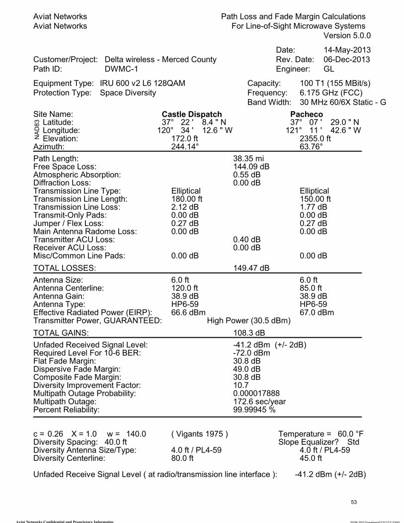
PATH INFORMATION: Castle Dispatch – Pacheco
PATH DESCRIPTION Path Length: 38.4 Miles Frequency Band: 6 GHz General Path Description: Path Description: This is a long path, with a difference of over 2100 ft in elevation between the sites. The control point along this path is a line of trees 0.5 miles from the proposed Castle Dispatch tower site, where the trees were measured at 75 feet. The vegetation along this path is a mix of tree types, of heights between 20 and 90 ft. A tree growth factor of 10 ft was added to accommodate expected future growth. Path Climate Considerations: Heightened humidity gradients provide additional signal paths through the atmosphere between radio sites which result in varying degrees of composite destructive and sometimes constructive interference at the receiving antenna. Space diversity is successfully deployed as a countermeasure against this atmospheric, refractive multi-path fading phenomenon but it does not provide much mitigation against harsher phenomenon that also occur in this region such as beam spreading, blackout fading/ducting and antenna decoupling, the latter of which is due to elevated incident signal arrival angle due to very high K factor path trajectory refractive bending. There are a number of design approaches that can help mitigate these harsher effects. One is to simply deploy relatively short path lengths. The effects are still there but they’re reduced to a manageable level. The second is to deploy ‘high-low’ path trajectories with a minimum of 6 milliradians (roughly ½ degree) of inclination angle. This path has an inclination angle of about 0.4 degrees, and should perform adequately.
51

7028-7
017/rw
eila
nd/1
31217:2
341
Aviat Networks Confidential and Proprietary Information
FINAL
0
200
400
600
800
1000
1200
1400
1600
1800
2000
2200
2400
02
46
810
12
14
16
18
20
22
24
26
28
30
32
34
36
38
38.4
E L E V A T I O N (ft)
DIS
TAN
CE (m
iles)
Terrain
Roughness: 484.1
Castle Dispatch
Pacheco
NAD83
NAD83
Site N
am
e:
Latitu
de N
:
Longitude W
:
Ele
vation A
MSL:
Cente
rlin
es A
GL:
Refe
rence M
ap:
Fie
ld V
erified:
Site N
am
e:
Latitu
de N
:
Longitude W
:
Ele
vation A
MSL:
Cente
rlin
es A
GL:
Refe
rence M
ap:
Engin
eer:
ID:
DW
MC
-1Fre
q =
6.1
75 G
Hz
17-D
ec-2
013
Delta wireless
Avia
t N
etw
ork
s
Avia
t N
etw
ork
s
Merc
ed C
ounty = 1.0
0 F1 @
K =
1
.33
......
= 0.6
0 F1 @
K =
1
.00
- -
.
= 0.6
0 F1 @
K =
1
.33
___
120.0
/ 8
0.0
ft
85.0
/ 4
5.0
ft
GL
37°
22 '
8.4
" N
120°
34 '
12.6
" W
37°
07 '
29.0
" N
121°
11 '
42.6
" W
172.0
ft
2355.0
ft
52
7028-7017/rweiland/131217:2340Aviat Networks Confidential and Proprietary Information
Aviat Networks
Aviat Networks
Path Loss and Fade Margin Calculations
For Line-of-Sight Microwave Systems
Version 5.0.0
Date: 14-May-2013
Customer/Project: Delta wireless - Merced County Rev. Date: 06-Dec-2013
Path ID: DWMC-1 Engineer: GL
Equipment Type: IRU 600 v2 L6 128QAM Capacity: 100 T1 (155 MBit/s)
Protection Type: Space Diversity Frequency: 6.175 GHz (FCC)
Band Width: 30 MHz 60/6X Static - G
Site Name: Castle Dispatch Pacheco
NAD83 Latitude:
Longitude:37° 22 ' 8.4 " N 37° 07 ' 29.0 " N
120° 34 ' 12.6 " W 121° 11 ' 42.6 " WElevation: 172.0 ft 2355.0 ft
Azimuth: 244.14° 63.76°
Path Length: 38.35 miFree Space Loss: 144.09 dBAtmospheric Absorption: 0.55 dBDiffraction Loss: 0.00 dBTransmission Line Type: Elliptical EllipticalTransmission Line Length: 180.00 ft 150.00 ftTransmission Line Loss: 2.12 dB 1.77 dBTransmit-Only Pads: 0.00 dB 0.00 dBJumper / Flex Loss: 0.27 dB 0.27 dBMain Antenna Radome Loss: 0.00 dB 0.00 dBTransmitter ACU Loss: 0.40 dBReceiver ACU Loss: 0.00 dBMisc/Common Line Pads: 0.00 dB 0.00 dB
TOTAL LOSSES: 149.47 dB
Antenna Size: 6.0 ft 6.0 ftAntenna Centerline: 120.0 ft 85.0 ftAntenna Gain: 38.9 dB 38.9 dBAntenna Type: HP6-59 HP6-59Effective Radiated Power (EIRP): 66.6 dBm 67.0 dBmTransmitter Power, GUARANTEED: High Power (30.5 dBm)
TOTAL GAINS: 108.3 dB
Unfaded Received Signal Level: -41.2 dBm (+/- 2dB)Required Level For 10-6 BER: -72.0 dBmFlat Fade Margin: 30.8 dBDispersive Fade Margin: 49.0 dBComposite Fade Margin: 30.8 dBDiversity Improvement Factor: 10.7Multipath Outage Probability: 0.000017888Multipath Outage: 172.6 sec/yearPercent Reliability: 99.99945 %
c = X = w =0.26 1.0 140.0 ( Vigants 1975 ) Temperature = 60.0 °FDiversity Spacing: 40.0 ftDiversity Antenna Size/Type: 4.0 ft / PL4-59 4.0 ft / PL4-59Diversity Centerline: 80.0 ft 45.0 ft
Slope Equalizer? Std
Unfaded Receive Signal Level ( at radio/transmission line interface ): -41.2 dBm (+/- 2dB)
53
TERMS AND CONDITIONS PATH ENGINEERING/ TRANSMISSION ENGINEERING
When Aviat Networks performs reliability calculations or path studies (path profiles from mapping or digitized data only) based solely on information supplied by or on behalf of the Customer, these calculations and studies are provided solely for budgetary purposes and shall not be construed as or be used for an installable design. When conducting a path survey, Aviat Networks will verify site coordinates and ground elevations, and record trees and man-made fixed obstructions on the path. This information will be recorded on the profile for that particular path. Aviat Networks will assign an appropriate growth factor to tree heights. When Aviat Networks performs frequency planning based, in part, on data provided by the Customer at the time of the study, Aviat Networks will not be responsible for any interference case that arises due to errors or omissions in such data. As the usage of microwave bands increase and there is more sharing with satellite services, it may be necessary to perform frequency interference studies and additional path surveys (to determine blockage) to alleviate the possibility of interference from satellite earth stations. Warranty of Path Engineering Services Aviat Networks warrants that the installed radio communication path will conform to Customer’s multipath performance reliability objectives when Aviat Networks has performed the path survey, recommended the path design, and Aviat Networks has implemented such recommendations. This warranty is for a period of 15 months from the date of the survey or one year from the date of installation of the microwave path, whichever expires first. All Aviat Networks field activities and
path propagation analysis will utilize current hardware, software, and engineering practice and judgment with the goal of meeting normal Path Loss, as defined in TIA/EIA Standard RS-252-A. Aviat Networks is not responsible for paths that it does not survey, nor for changes in path design beyond those specifically allowed in the path survey report or in writing after the field survey is completed, including but not limited to: Any change in path design; Any movement in site locations; Any building or other structure built on-path after
date of survey; Any disturbance of the terrain which may cause
blockage or reflection; Any additional frequency interference source; Any change of available antenna mounting space
on tower. Any one or more of the changes listed on page one will nullify this warranty, and the Customer shall in such case bear the total cost of determining that such change was the cause. Aviat Networks will not be responsible for degraded path performance when such degradation is due to such anomalous propagation conditions as: Long-term loss of fade margin due to antenna
decoupling misalignment caused by widely-varying k-factor changes;
Long-term loss of fade margin due to Atmospheric Boundary Layering (“ABL”) causing wavefront defocusing (beam spreading), signal entrapment (blackout fading), ducting, and other such occurrence.
Path Engineering Services Aviat Networks will perform radio path surveys and path calculations to determine the normal path loss and antenna heights as defined in TIA/EIA Standard RS-252-A
54

MICROWAVE PATH SURVEY REPORT AVIAT NETWORKS
Excessive rain outage rates beyond the published crane and/or chart data used in the calculation;
Degradation resulting from certain types of multipath interference attributed to unidentifiable off-path terrain features or structures;
Any other technological or atmospheric condition not foreseeable through the exercise of prudent engineering knowledge and judgment.
Additionally, Aviat Networks will not be responsible for degraded path performance when: Non-Aviat Networks radio equipment is installed on
a surveyed path; Aviat Networks radio equipment is not installed by
Aviat Networks; Existing antenna and waveguide system is used
without test and inspection performed by Aviat Networks.
Aviat Networks designs the microwave path based upon best engineering practices and standards common to the industry, and it selects a transmission configuration based upon the most economical method for meeting the path performance objectives. When path loss or reliability objectives are not achieved, exclusive of anomalous propagation or path changes as described above, then Customer’s sole remedy, and Aviat Networks’ exclusive liability in connection with path engineering, shall be that Aviat Networks will provide incremental labor and material to optimize the antenna system beyond what would have been required during initial installation. Where anomalous propagation is suspected in an installed microwave path, Aviat Networks will work with the Customer to obtain reasonable evidence that such condition exists. The total retroactive costs for such study shall be the responsibility of the Customer with Aviat Networks providing in-office engineering support. The cost of relocating towers, antennas, passive reflectors or other measures required to remedy this type of problem shall solely be the responsibility of the Customer.
Limitations The foregoing warranties are in lieu of all other warranties whether oral, written, expressed, implied, or statutory. In particular, THE IMPLIED WARRANTIES OF FITNESS FOR PARTICULAR PURPOSE AND MERCHANTABILITY ARE HEREBY DISCLAIMED and shall not be applicable, either from Aviat Networks or any other equipment or software manufacturer. Aviat Networks’ warranty obligations and Customer’s remedies thereunder are solely and exclusively as stated herein. IN NO CASE SHALL AVIAT NETWORKS BE LIABLE FOR INDIRECT KINDS OF DAMAGES, INCLUDING BUT NOT LIMITED TO SPECIAL, INCIDENTAL, AND CONSEQUENTIAL DAMAGES, OR LOSS OF CAPITAL, REVENUE, OR PROFITS. In no event shall Aviat Networks’ liability to customer, or any party claiming through Customer, be in excess of the actual sales price paid by Customer for any service supplied to Customer by Aviat Networks.
55