millimetre wave limb sounder - home | …ceoi.ac.uk/static/media/uploads/docs/workshops/passive...
TRANSCRIPT
INSTRUMENT ARCHITECTURE:
MARSCHALS
MILLIMETRE WAVE LIMB SOUNDER
Brian Moyna
Millimetre Technology Group, RAL Space
Rutherford Appleton Laboratory, UK
Outline
• Definition
• History
• Original instrument
• SCOUT-O3
• UAMS
• PREMIER-Ex, ESSenCe
• Future: NSTP, SHIRM, Spectrometer, Pointing,
Future campaigns
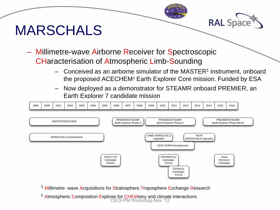
MARSCHALS
– Millimetre-wave Airborne Receiver for Spectroscopic
CHaracterisation of Atmospheric Limb-Sounding
– Conceived as an airborne simulator of the MASTER1 instrument, onboard
the proposed ACECHEM2 Earth Explorer Core mission. Funded by ESA
– Now deployed as a demonstrator for STEAMR onboard PREMIER, an
Earth Explorer 7 candidate mission
1 Millimetre- wave Acquisitions for Stratosphere Troposphere Exchange Research
2 Atmospheric Composition Explorer for CHEMistry and climate interactions
CEOI PM Workshop Nov ‘12
MARSCHALS Development
SCOUT-O3 Campaign
Darwin
UAMS MARSCHALS Upgrades
ESSenCeCampaign,
Kiruna
PREMIER-Ex Campaign,
Kiruna
NSTPMARSCHALS Upgrades
PREMIER/STEAMREarth Explorer Phase A
MASTER/ACECHEMPREMIER/STEAMR
Earth Explorer Phase 0
1999 2000 2001 2002 2003 2004 2005 2006 2007 2008 2009 2010 2011 2012 2013 2014 2015 2016
Asian Monsoon Campaign
PREMIER/STEAMREarth Explorer Phase B/C/D
CEOI SHIRM Development
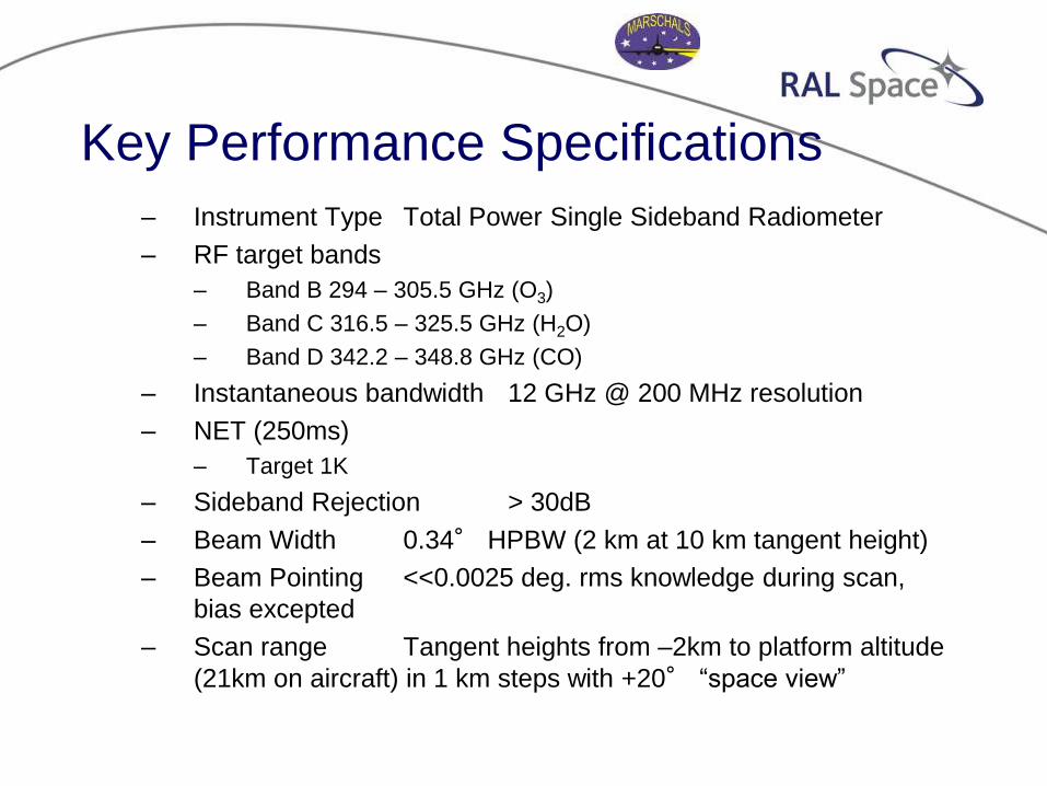
Key Performance Specifications
– Instrument Type Total Power Single Sideband Radiometer
– RF target bands
– Band B 294 – 305.5 GHz (O3)
– Band C 316.5 – 325.5 GHz (H2O)
– Band D 342.2 – 348.8 GHz (CO)
– Instantaneous bandwidth 12 GHz @ 200 MHz resolution
– NET (250ms)
– Target 1K
– Sideband Rejection > 30dB
– Beam Width 0.34° HPBW (2 km at 10 km tangent height)
– Beam Pointing <<0.0025 deg. rms knowledge during scan,
bias excepted
– Scan range Tangent heights from –2km to platform altitude
(21km on aircraft) in 1 km steps with +20° “space view”
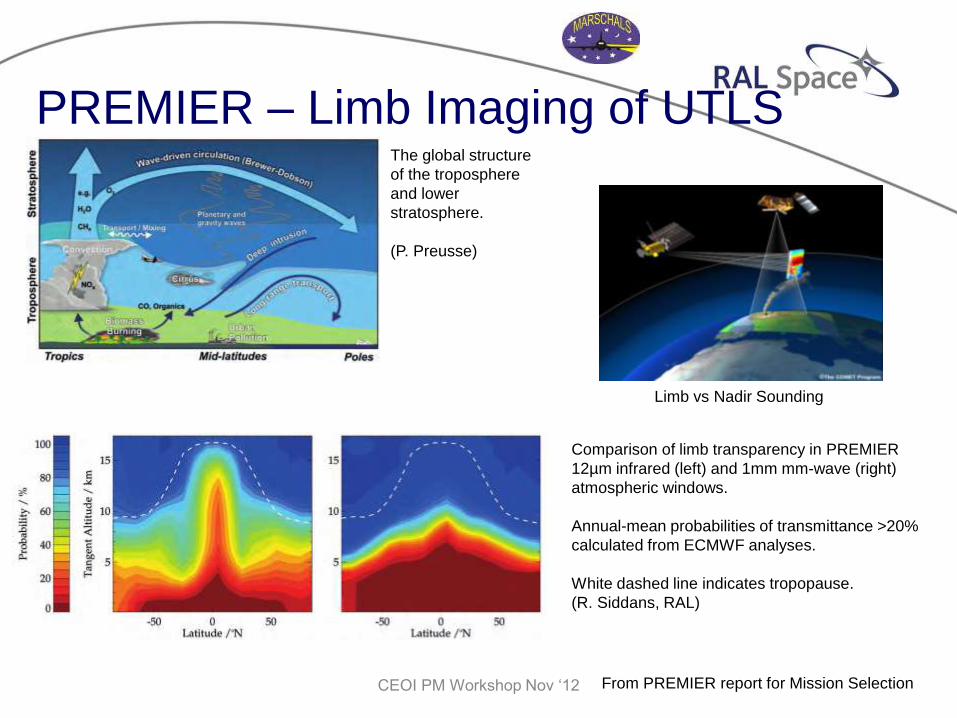
PREMIER – Limb Imaging of UTLS The global structure
of the troposphere
and lower
stratosphere.
(P. Preusse)
Comparison of limb transparency in PREMIER
12µm infrared (left) and 1mm mm-wave (right)
atmospheric windows.
Annual-mean probabilities of transmittance >20%
calculated from ECMWF analyses.
White dashed line indicates tropopause.
(R. Siddans, RAL)
From PREMIER report for Mission Selection CEOI PM Workshop Nov ‘12
Limb vs Nadir Sounding
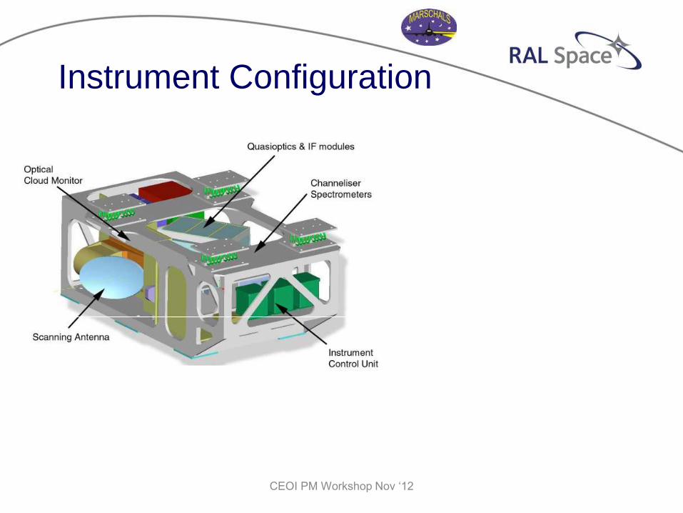
Instrument Configuration
CEOI PM Workshop Nov ‘12
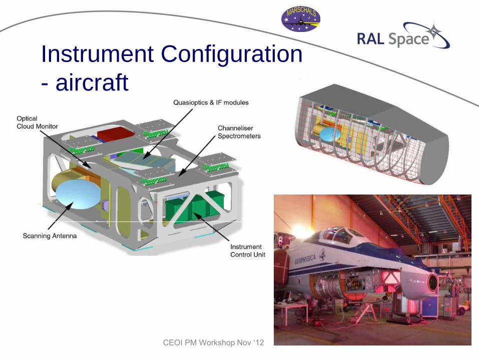
Instrument Configuration
- aircraft
CEOI PM Workshop Nov ‘12
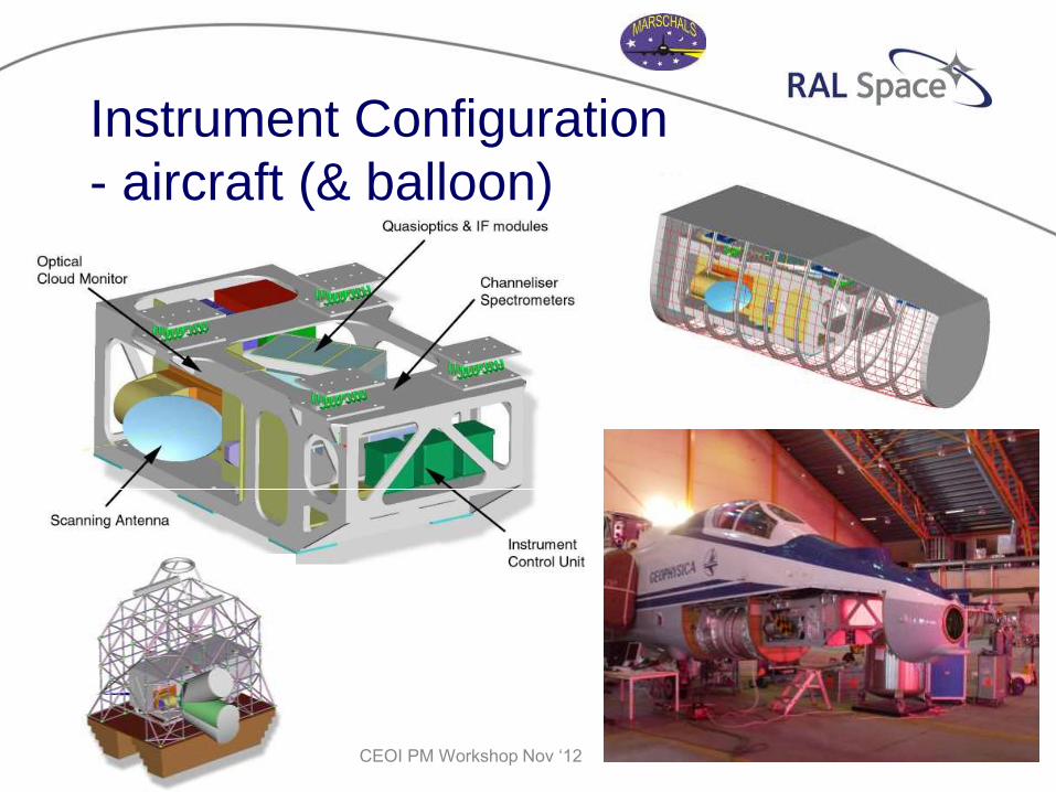
Instrument Configuration
- aircraft (& balloon)
CEOI PM Workshop Nov ‘12
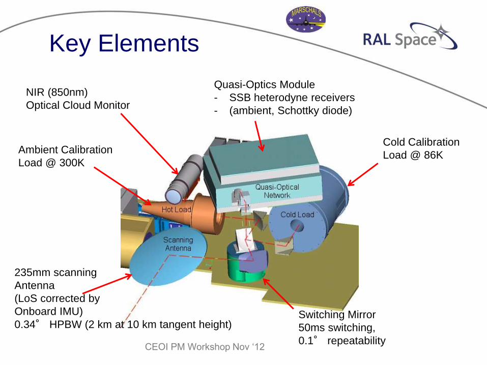
Key Elements
Cold Calibration
Load @ 86K Ambient Calibration
Load @ 300K
Quasi-Optics Module
- SSB heterodyne receivers
- (ambient, Schottky diode)
Switching Mirror
50ms switching,
0.1° repeatability
235mm scanning
Antenna
(LoS corrected by
Onboard IMU)
0.34° HPBW (2 km at 10 km tangent height)
NIR (850nm)
Optical Cloud Monitor
CEOI PM Workshop Nov ‘12
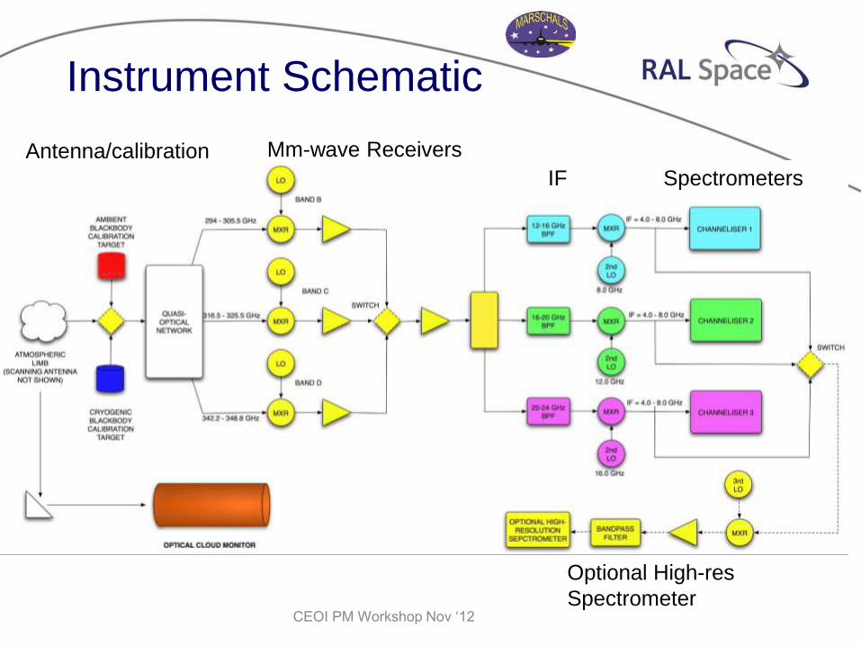
Instrument Schematic
Optional High-res
Spectrometer
Antenna/calibration Mm-wave Receivers
IF Spectrometers
CEOI PM Workshop Nov ‘12
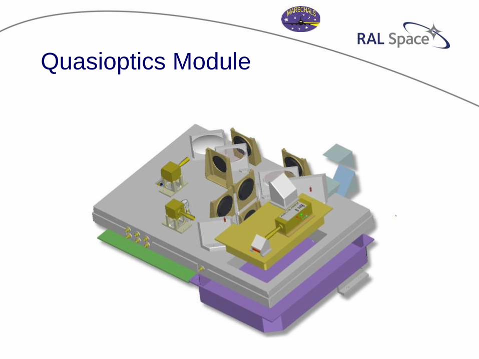
Quasioptics Module
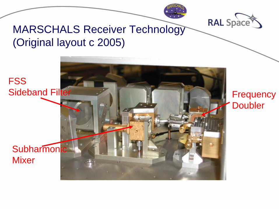
FSS
Sideband Filter
Subharmonic
Mixer
Frequency
Doubler
MARSCHALS Receiver Technology
(Original layout c 2005)
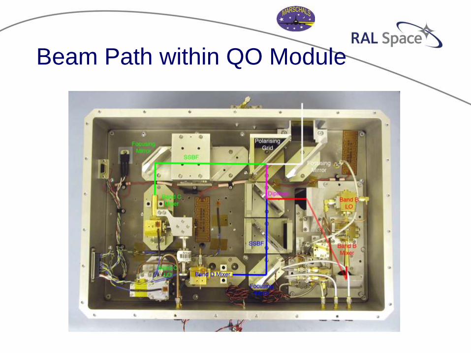
Beam Path within QO Module
Band B
Band C
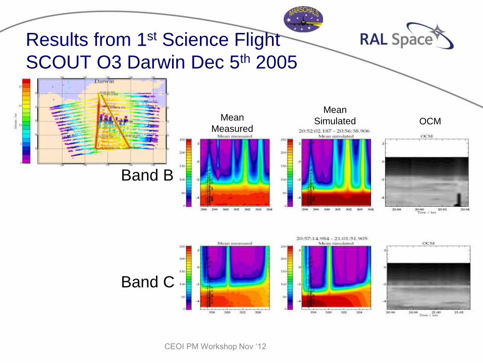
Results from 1st Science Flight
SCOUT O3 Darwin Dec 5th 2005
Mean
Measured
Mean
Simulated OCM
CEOI PM Workshop Nov ‘12
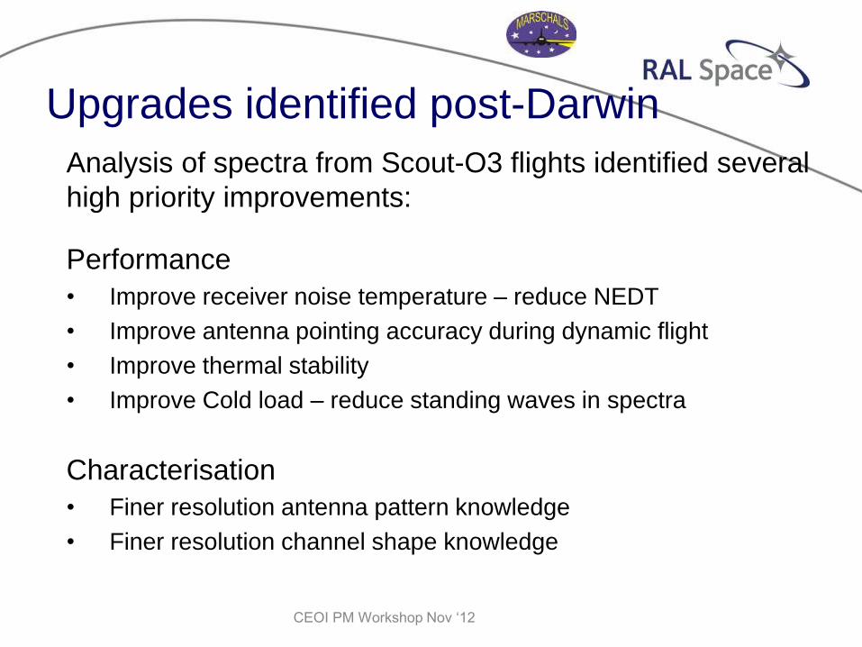
Upgrades identified post-Darwin
Analysis of spectra from Scout-O3 flights identified several
high priority improvements:
Performance
• Improve receiver noise temperature – reduce NEDT
• Improve antenna pointing accuracy during dynamic flight
• Improve thermal stability
• Improve Cold load – reduce standing waves in spectra
Characterisation
• Finer resolution antenna pattern knowledge
• Finer resolution channel shape knowledge
CEOI PM Workshop Nov ‘12
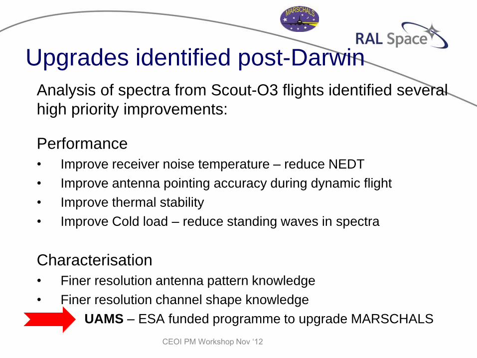
Upgrades identified post-Darwin
Analysis of spectra from Scout-O3 flights identified several
high priority improvements:
Performance
• Improve receiver noise temperature – reduce NEDT
• Improve antenna pointing accuracy during dynamic flight
• Improve thermal stability
• Improve Cold load – reduce standing waves in spectra
Characterisation
• Finer resolution antenna pattern knowledge
• Finer resolution channel shape knowledge
UAMS – ESA funded programme to upgrade MARSCHALS
CEOI PM Workshop Nov ‘12

QON Pre-Upgrade
Band B
Receiver RAL
Band D
Receiver
RAL
Band C
Receiver
CEOI PM Workshop Nov ‘12
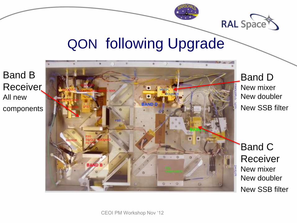
QON following Upgrade
Band B
Receiver All new
components
Band D New mixer
New doubler
New SSB filter
Band C
Receiver New mixer
New doubler
New SSB filter
CEOI PM Workshop Nov ‘12
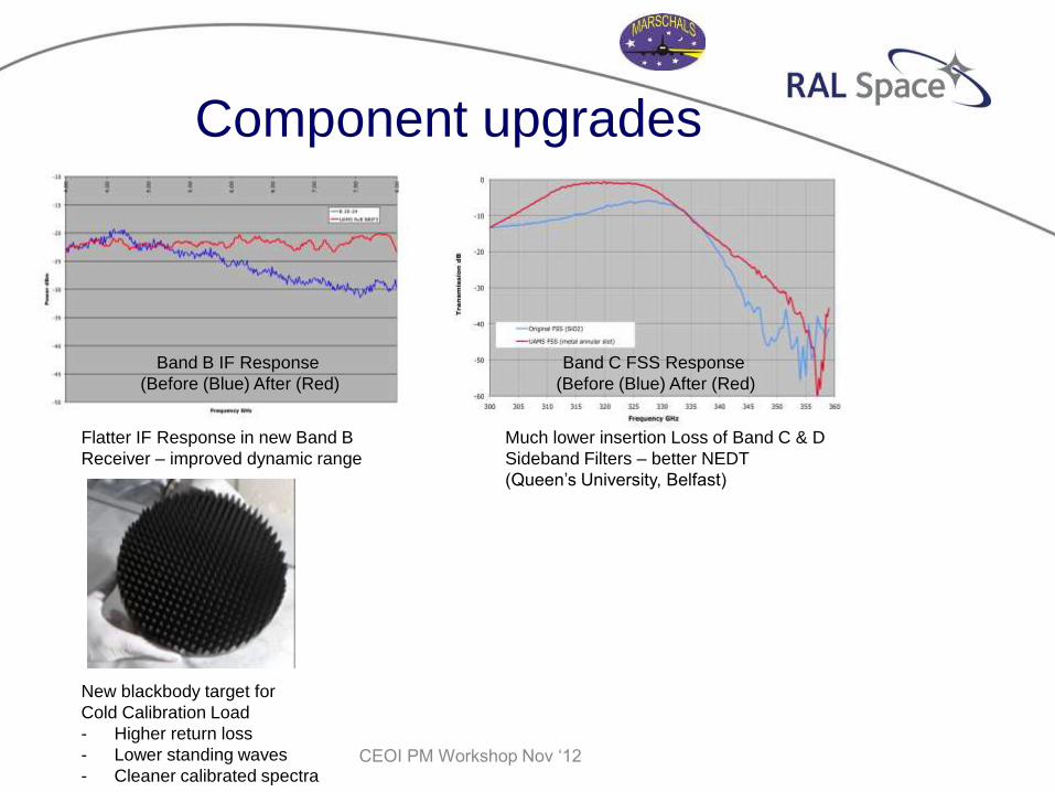
Component upgrades
Band B IF Response
(Before (Blue) After (Red)
Band C FSS Response
(Before (Blue) After (Red)
Flatter IF Response in new Band B
Receiver – improved dynamic range
Much lower insertion Loss of Band C & D
Sideband Filters – better NEDT
(Queen’s University, Belfast)
New blackbody target for
Cold Calibration Load
- Higher return loss
- Lower standing waves
- Cleaner calibrated spectra CEOI PM Workshop Nov ‘12
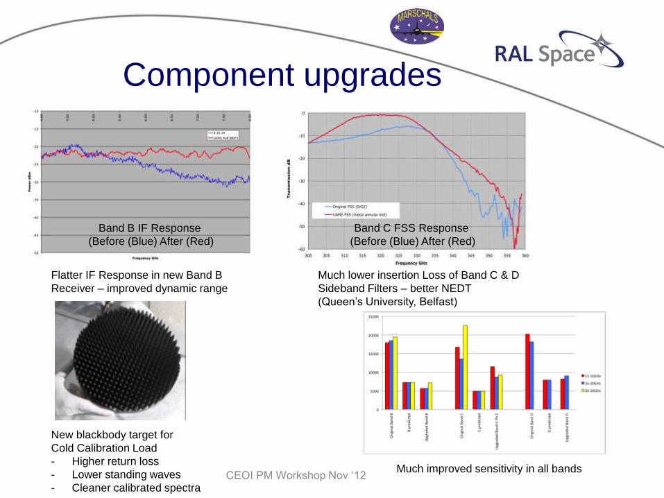
Much improved sensitivity in all bands
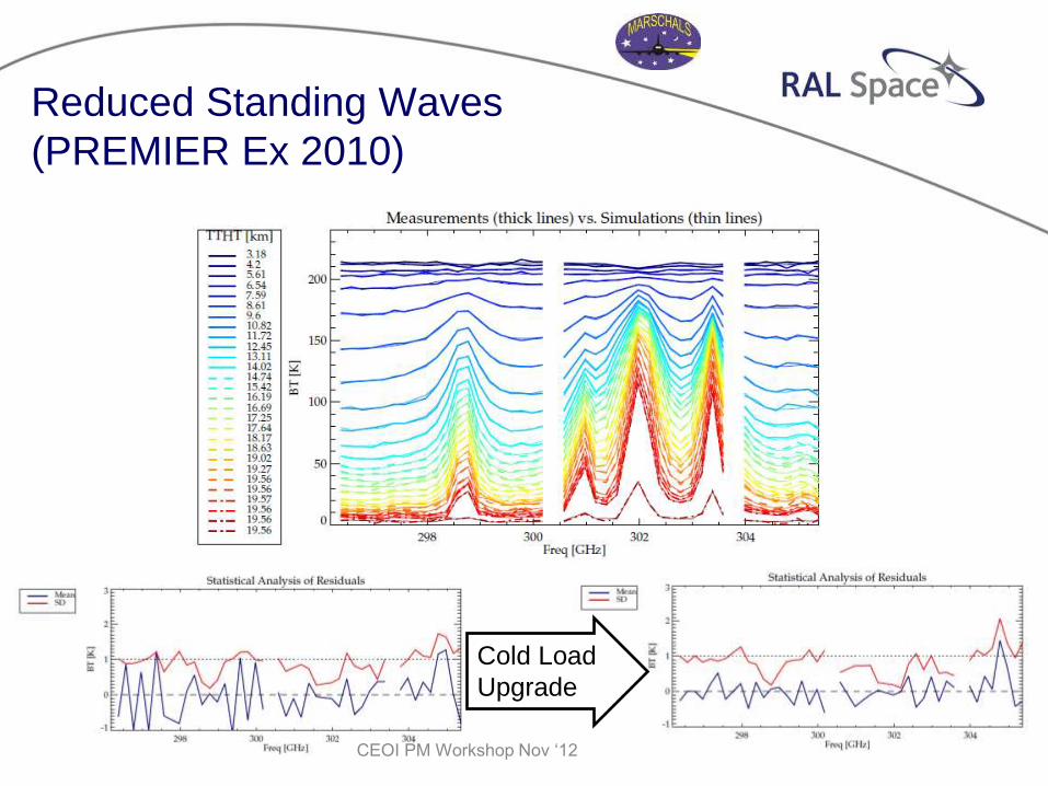
Reduced Standing Waves
(PREMIER Ex 2010)
Cold Load
Upgrade
CEOI PM Workshop Nov ‘12
Improvements in Measurement
Performance after UAMS Upgrade
• Lower receiver noise temperatures leads to reduced ΔNEBT,
and therefore lower measurement noise.
• Improved blackbody termination of the cold calibration target
mitigates calibration errors and standing wave pattern in cold
sky spectra.
• More frequent and more reliable pointing bias corrections mean
less observation time is lost after aircraft turns (or other
pointing problems).
• Upgraded computer stacks, power supplies and thermal
stability improve operational reliability.
CEOI PM Workshop Nov ‘12
Future upgrades
UK National funding secured for 2 year programme of major
upgrades to MARSCHALS:
• Context : UK support for STEAMR
– Replacement of Band D receiver with one based on
sideband separating mixer (SHIRM) technology
– (being developed with CEOI support)
– Addition of high resolution spectrometer – digital
autocorrelator or Fourier Transform type (TBC)
– UK spectrometer development being supported by
CEOI
– Additional flights (further collaborative proposals to e.g.
FP7, ESA are in preparation)
CEOI PM Workshop Nov ‘12
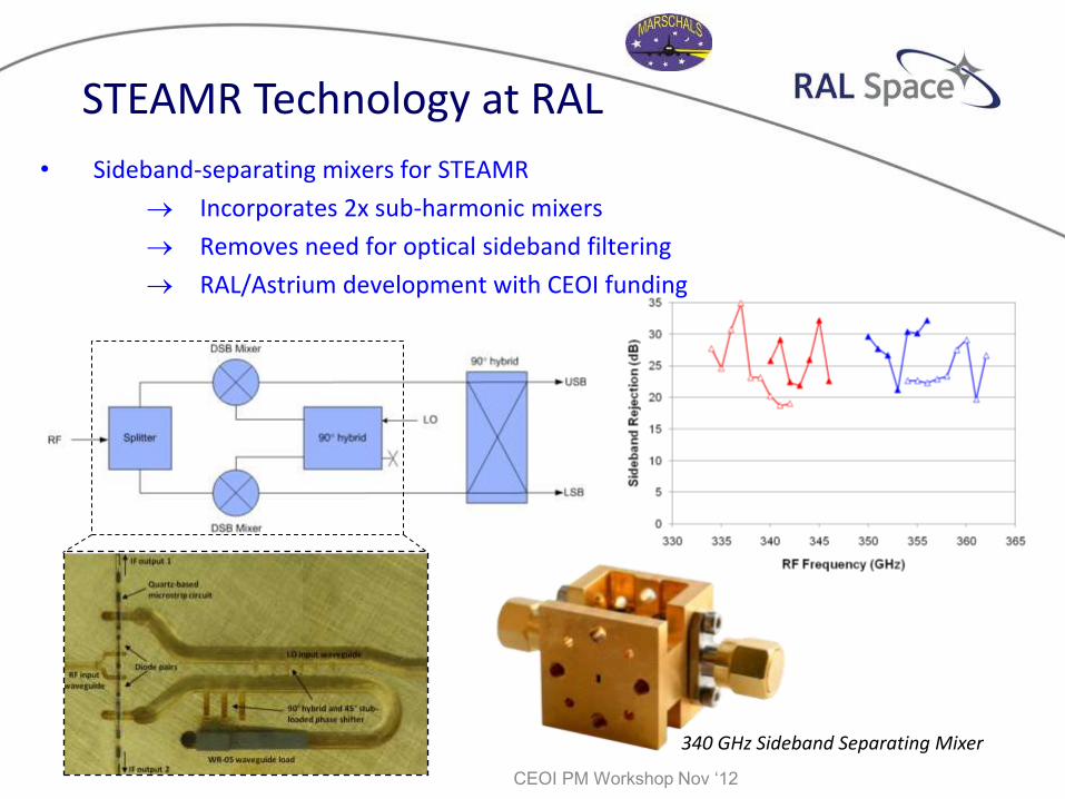
STEAMR Technology at RAL
• Sideband-separating mixers for STEAMR
Incorporates 2x sub-harmonic mixers
Removes need for optical sideband filtering
RAL/Astrium development with CEOI funding
340 GHz Sideband Separating Mixer
CEOI PM Workshop Nov ‘12
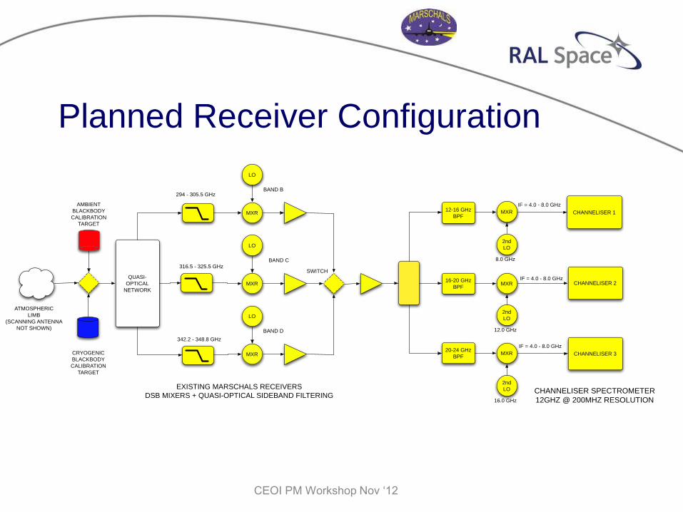
Planned Receiver Configuration
12-16 GHz
BPF
16-20 GHz
BPF
20-24 GHz
BPF
MXR
MXR
MXR
2nd
LO
2nd
LO
2nd
LO
8.0 GHz
12.0 GHz
16.0 GHz
IF = 4.0 - 8.0 GHz
CHANNELISER 1
IF = 4.0 - 8.0 GHzCHANNELISER 2
IF = 4.0 - 8.0 GHz
CHANNELISER 3CRYOGENIC
BLACKBODY
CALIBRATION
TARGET
AMBIENT
BLACKBODY
CALIBRATION
TARGET
MXR
LO
MXR
LO
MXR
LO
SWITCHQUASI-
OPTICAL
NETWORK
ATMOSPHERIC
LIMB
(SCANNING ANTENNA
NOT SHOWN)
294 - 305.5 GHz
342.2 - 348.8 GHz
316.5 - 325.5 GHz
BAND B
BAND C
BAND D
EXISTING MARSCHALS RECEIVERS
DSB MIXERS + QUASI-OPTICAL SIDEBAND FILTERINGCHANNELISER SPECTROMETER
12GHZ @ 200MHZ RESOLUTION
CEOI PM Workshop Nov ‘12
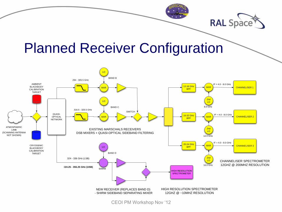
Planned Receiver Configuration
CEOI PM Workshop Nov ‘12
12-16 GHz
BPF
16-20 GHz
BPF
20-24 GHz
BPF
MXR
MXR
MXR
2nd
LO
2nd
LO
2nd
LO
8.0 GHz
12.0 GHz
16.0 GHz
IF = 4.0 - 8.0 GHz
CHANNELISER 1
IF = 4.0 - 8.0 GHzCHANNELISER 2
IF = 4.0 - 8.0 GHz
CHANNELISER 3CRYOGENIC
BLACKBODY
CALIBRATION
TARGET
AMBIENT
BLACKBODY
CALIBRATION
TARGET
MXR
LO
MXR
LO
SWITCHQUASI-
OPTICAL
NETWORK
ATMOSPHERIC
LIMB
(SCANNING ANTENNA
NOT SHOWN)
294 - 305.5 GHz
316.5 - 325.5 GHz
BAND B
BAND C
EXISTING MARSCHALS RECEIVERS
DSB MIXERS + QUASI-OPTICAL SIDEBAND FILTERING
CHANNELISER SPECTROMETER
12GHZ @ 200MHZ RESOLUTION
LO
324 - 336 GHz (LSB)
324.25 - 355.25 GHz (USB)
BAND D
SHIRMHIGH RESOLUTION
SPECTROMETER
NEW RECEIVER (REPLACES BAND D)
- SHIRM SIDEBAND SEPARATING MIXER
HIGH RESOLUTION SPECTROMETER
12GHZ @ ~10MHZ RESOLUTION
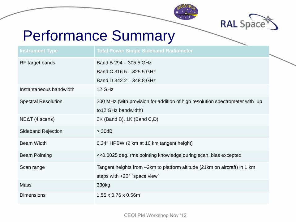
Performance Summary Instrument Type Total Power Single Sideband Radiometer
RF target bands Band B 294 – 305.5 GHz
Band C 316.5 – 325.5 GHz
Band D 342.2 – 348.8 GHz
Instantaneous bandwidth 12 GHz
Spectral Resolution 200 MHz (with provision for addition of high resolution spectrometer with up
to12 GHz bandwidth)
NEΔT (4 scans) 2K (Band B), 1K (Band C,D)
Sideband Rejection > 30dB
Beam Width 0.34° HPBW (2 km at 10 km tangent height)
Beam Pointing <<0.0025 deg. rms pointing knowledge during scan, bias excepted
Scan range Tangent heights from –2km to platform altitude (21km on aircraft) in 1 km
steps with +20° “space view”
Mass 330kg
Dimensions 1.55 x 0.76 x 0.56m
CEOI PM Workshop Nov ‘12
Summary
• MARSCHALS – into its 2nd decade
• Continuous upgrades keep it relevant as an airborne
demonstrator of planned spaceborne mm-wave limb
sounders
• Next upgrades will enable closest simulation yet of
PREMIER, operating alongside GLORIA-AB IR Limb
imaging spectrometer
CEOI PM Workshop Nov ‘12
Summary
• MARSCHALS – into its 2nd decade
• Continuous upgrades keep it relevant as an airborne
demonstrator of planned spaceborne mm-wave limb
sounders
• Next upgrades will enable closest simulation yet of
PREMIER, operating alongside GLORIA-AB IR Limb
imaging spectrometer – time & place TBD!
CEOI PM Workshop Nov ‘12