minerva main injector experiment for -a is the symbol for the neutrino. the beam that is sent to...
TRANSCRIPT
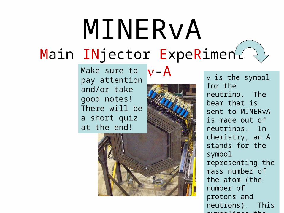
MINERvAMain INjector ExpeRiment for -A
is the symbol for the neutrino. The beam that is sent to MINERvA is made out of neutrinos. In chemistry, an A stands for the symbol representing the mass number of the atom (the number of protons and neutrons). This symbolizes the different types of atoms found in MINERvA.
Make sure to pay attention and/or take good notes! There will be a short quiz at the end!
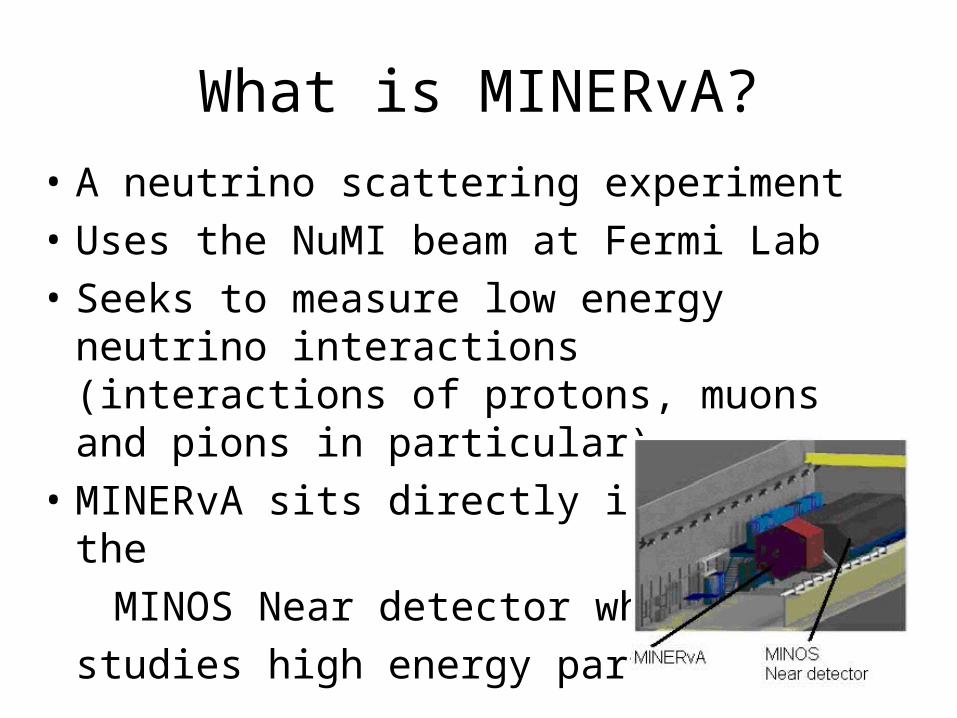
What is MINERvA?
• A neutrino scattering experiment
• Uses the NuMI beam at Fermi Lab
• Seeks to measure low energy neutrino interactions (interactions of protons, muons and pions in particular)
• MINERvA sits directly in front of the
MINOS Near detector which
studies high energy particles

How is MINERvA constructed?
Here is one plane of MINERvA being prepared for installation. There are around 200 planes in MINERvA (it changes with every modification). The detector is in the shape of a hexagon. The center of the plane will also be filled with detection material.
MINERvA is made of many planes of nuclear targets and scintillator material. The nuclear targets are dense materials which offer the particles a large nucleus to interact with. The scintillator material detects particles as they travel through the plane.
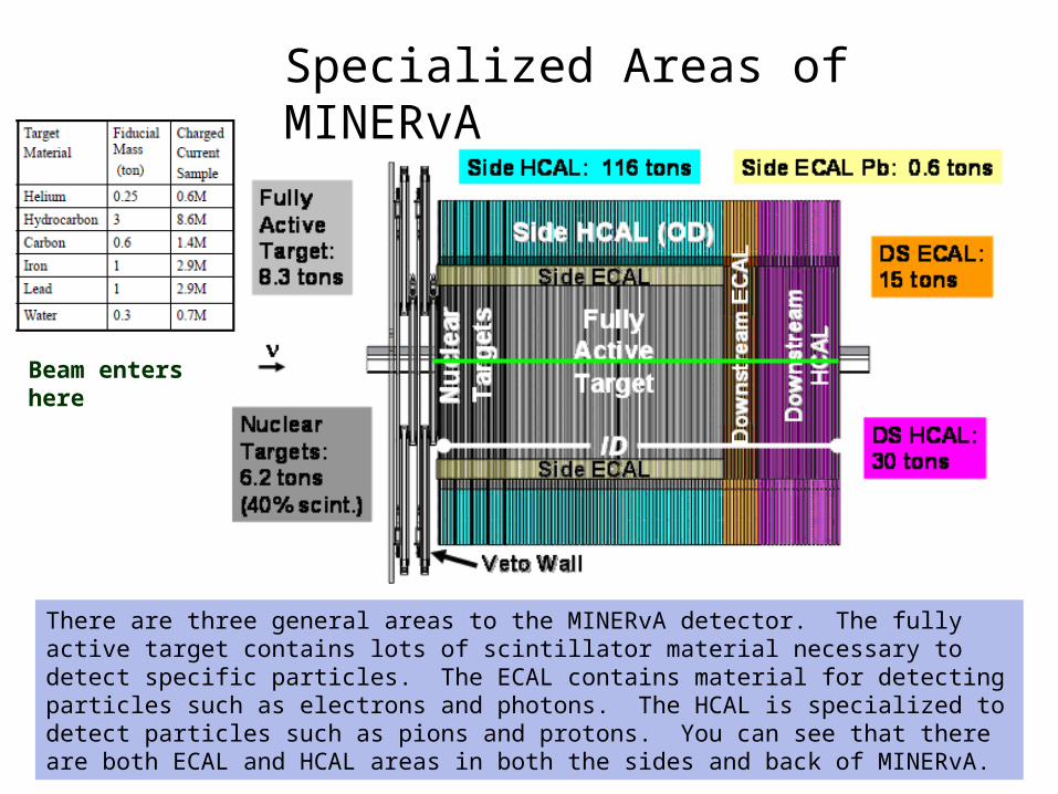
Specialized Areas of MINERvA
Beam enters here
There are three general areas to the MINERvA detector. The fully active target contains lots of scintillator material necessary to detect specific particles. The ECAL contains material for detecting particles such as electrons and photons. The HCAL is specialized to detect particles such as pions and protons. You can see that there are both ECAL and HCAL areas in both the sides and back of MINERvA.

The ECAL and HCAL ModulesThe ECAL and HCAL Modules
The ECAL is located in the outside border of each plane and also in the orange colored portion in the diagram. The HCAL modules are also located in the outer border of the plane and in the purple portion of the diagram.
A typical HCAL ModuleA typical ECAL Module
HCAL
ECAL

The Fully Active Target – The Fiducial Zone
This area is the “sweet spot” of the detector. It contains three different directional layers of triangular graphite material. This material is the scintillating material. It carries the energy released by the particles into the detector to tiny fibers inside the graphite which connect to photomultipliers which send the data to the computers. The computers can tell us even more about the particles.
We label these layers the X, U and V views. Due to the three layers, we can “see” where the events happened in the detector.
ALL THREE LAYERED TOGETHER

The Scintillator Strips
These are small strips which are triangular shaped and are formed in long pieces. These strips take the energy from a particle interacting with the material in the detector and transform it into light. The wavelength shifting fiber runs through the length of the scintillator and collects the light. The light is then sent to the PMTs.
This shows how the scintillator strips fit together in a panel. Because of their shape, each particle will leave energy in at least two strips. This helps the computers to identify more accurately where the event happened in the detector.
Here is the “big picture”. You can see the scintillator and wavelength shifting fiber on left connected to the PMT box. The PMTs are photomultipliers which transform the light energy into electricity and strengthen the signal. This needs to take place since the amount of light emitted per event is very small.
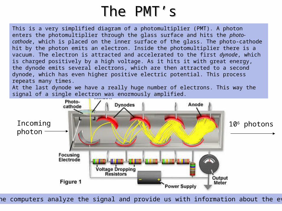
The PMT’sThe PMT’s
Next, the computers analyze the signal and provide us with information about the event.
This is a very simplified diagram of a photomultiplier (PMT). A photon enters the photomultiplier through the glass surface and hits the photo-cathode, which is placed on the inner surface of the glass. The photo-cathode hit by the photon emits an electron. Inside the photomultiplier there is a vacuum. The electron is attracted and accelerated to the first dynode, which is charged positively by a high voltage. As it hits it with great energy, the dynode emits several electrons, which are then attracted to a second dynode, which has even higher positive electric potential. This process repeats many times. At the last dynode we have a really huge number of electrons. This way the signal of a single electron was enormously amplified.
Incoming photon
106 photons
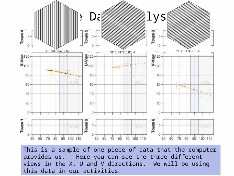
The Data Analysis
This is a sample of one piece of data that the computer provides us. Here you can see the three different views in the X, U and V directions. We will be using this data in our activities.
The Quiz!!Number your paper 1 – 8 giving each answer plenty of
room – some questions have more than one answer. Yes, there are only 8 questions!!
1. What does the MINERvA detector measure?
2. What shape are each of the planes in MINERvA?
3. What is a scintillator strip?
4. What is the shape of a scintillator strip?
5. How many specialized areas are in MINERvA?
6. Name three types of material in MINERvA.
7. What is a wavelength shifting fiber?
8. What does a PMT do?