minimizing base column demands in multi-story buckling
TRANSCRIPT

Brigham Young University Brigham Young University
BYU ScholarsArchive BYU ScholarsArchive
Theses and Dissertations
2010-12-01
Minimizing Base Column Demands in Multi-Story Buckling Minimizing Base Column Demands in Multi-Story Buckling
Restrained Braced Frames Using Genetic Algorithms Restrained Braced Frames Using Genetic Algorithms
Christopher Hiroshi Yeates Brigham Young University - Provo
Follow this and additional works at: https://scholarsarchive.byu.edu/etd
Part of the Civil and Environmental Engineering Commons
BYU ScholarsArchive Citation BYU ScholarsArchive Citation Yeates, Christopher Hiroshi, "Minimizing Base Column Demands in Multi-Story Buckling Restrained Braced Frames Using Genetic Algorithms" (2010). Theses and Dissertations. 2901. https://scholarsarchive.byu.edu/etd/2901
This Thesis is brought to you for free and open access by BYU ScholarsArchive. It has been accepted for inclusion in Theses and Dissertations by an authorized administrator of BYU ScholarsArchive. For more information, please contact [email protected], [email protected].

Minimizing Base Column Demands in Multi-Story
Buckling-Restrained Braced Frames Using
Genetic Algorithms
Christopher H. Yeates
A thesis submitted to the faculty of Brigham Young University
in partial fulfillment of the requirements for the degree of
Master of Science
Paul W. Richards, Chair Richard J. Balling Travis M. Gerber
Department of Civil & Environmental Engineering
Brigham Young University
December 2010
Copyright © 2010 Christopher H. Yeates
All Rights Reserved


ABSTRACT
Minimizing Base Column Demands in Multi-Story
Buckling-Restrained Braced Frames Using
Genetic Algorithms
Christopher H. Yeates
Department of Civil & Environmental Engineering
Master of Science
Most structural optimization procedures focus on minimizing the total volume of steel in an attempt to reduce overall costs. However, many other factors can have an effect on the overall cost of a structure. Base column demands in particular, can affect base plate sizes, anchorage, and foundation design. Researchers have found that present methods for estimating column demands are too conservative. Nonlinear time history analyzes were conducted on buckling-restrained braced frames of six heights. Optimized results were found considering three ductility constraints and two optimization objectives. The two optimization objectives were minimized total brace area and minimized base column demands. The results show that designs created by using a minimized column demand objective led to column demands that ranged from 2 to 6% lower than column demands in designs generated by a total brace area minimizing objective. The average brace areas of the designs produced by the total brace area minimizing objective were 25 to 80% less than the designs produced by the column demand minimizing objective. Results showed that large braces in the top stories did not have an effect on column demands in the ground level story. The results indicate that base column demands can be minimized by minimizing braces areas. However, braces areas cannot be minimized by minimizing base column demands. Keywords: BRBF, buckling-restrained braces, column demands, optimization, genetic algorithm


ACKNOWLEDGMENTS
I would like to thank Dr. Paul W. Richards for his help and encouragement as I dealt with
the steep learning curve of OpenSEES. His input and feedback during the writing process was
also invaluable and for that I am grateful. I would also like to thank Dr. Richard J. Balling and
Dr. Travis M. Gerber for the things that they have taught me during my time at Brigham Young
University. Their courses provided me with the foundation that I needed to complete this study.
More importantly, all three of these professors have taught me life lessons that will continue to
bless my life as I proceed to the next chapters of my life. I am grateful for my beautiful wife who
was so supportive during the entire process. Her encouragement and love helped me finish what I
started a year ago. I also thank my parents for raising me to understand the importance of an
education and instilling a love for learning in me. Their love and examples have led me to where
I am today.


v
TABLE OF CONTENTS
LIST OF TABLES ...................................................................................................................... vii
LIST OF FIGURES ..................................................................................................................... ix
1 Introduction ........................................................................................................................... 1
2 Background and Previous Studies ....................................................................................... 3
2.1 Buckling-Restrained Braced Frames – An Overview ..................................................... 3
2.2 Early Buckling-Restrained Braced Frames ..................................................................... 5
2.3 BRB Analytical Studies .................................................................................................. 7
2.4 BRB Experimental Studies ............................................................................................. 9
2.5 Optimization ................................................................................................................. 12
3 Current Design Procedures ................................................................................................ 17
3.1 Sizing Braces in Buckling-Restrained Braced Frames ................................................. 17
3.2 Sizing Columns in Buckling-Restrained Braced Frames ............................................. 18
4 Modeling .............................................................................................................................. 21
4.1 Frames ........................................................................................................................... 21
4.2 OpenSEES Materials and Elements .............................................................................. 22
4.3 Ground Motions ............................................................................................................ 24
5 Optimization Procedure ..................................................................................................... 27
6 Discussion of Results ........................................................................................................... 33
6.1 Comparison of Normalized Brace Areas ...................................................................... 34
6.2 Comparison of Ductility Demands ............................................................................... 45
6.3 Comparison of Column Demands ................................................................................. 48
6.4 Comparison of Design Column Demands and Actual Column Demands .................... 51
7 Summary and Conclusions ................................................................................................. 57
vi
References .................................................................................................................................... 59
Appendix A. Figures .............................................................................................................. 63
A.1 Normalized Brace Areas for Frames with Ductility Limit of 1.0 ...................................... 63
A.2 Normalized Brace Areas for Frames with Ductility Limit of 7.0 ...................................... 66
A.3 Ductility of Frames with Ductility Limit of 1.0 ................................................................. 69
A.4 Ductility of Frames with Ductility Limit of 7.0 ................................................................. 72
Appendix B. Source Code ..................................................................................................... 75
B.1 Main_force.tcl .................................................................................................................... 75
B.2 AppAnalysis_force.v6.tcl ................................................................................................... 82
B.3 Main_area.tcl ...................................................................................................................... 88
B.4 AppAnalysis_area.v6.tcl .................................................................................................... 96
B.5 Input_ddv.v8.tcl ............................................................................................................... 102
B.6 Random_Selection_Crossover_Mutation.tcl ................................................................... 120
B.7 Maximum_Fitness.tcl ....................................................................................................... 129
B.8 AppInitialize.v7.tcl ........................................................................................................... 130
B.9 Gravity_Analysis.v5.tcl .................................................................................................... 137
B.10 Dynamic_Analysis.v6.tcl ............................................................................................... 140
B.11 EqScaling.tcl .................................................................................................................. 147

vii
LIST OF TABLES
Table 5-1: Optimization Procedure Parameters ............................................................................ 31
Table 6-1: Summary of Frames Designed .................................................................................... 33
Table 6-2: Comparison of Average Brace Areas with Allowable Ductility of 3.5 ....................... 34
Table 6-3: Comparison of the Maximum Axial Demands (Ductility Limit of 3.5) ..................... 50
Table 6-4: A Comparison of Pabh and Puth Using Total Brace Area Optimization (Ductility Limit of 3.5) .......................................................................................................................... 51
Table 6-5: A Comparison of Pabh and Puth Using Column Demand Optimization (Ductility Limit of 3.5) .......................................................................................................................... 52
Table 6-6: Story Where Cumulative Pabh Exceeds Puth (Ductility Limit of 3.5) ....................... 53
Table 6-7: Summary of the Nine-Story BRBF Example .............................................................. 54

viii

ix
LIST OF FIGURES
Figure 2-1: Buckling Restrained Brace (Aiken et al. 2000. Used without permission) ................. 4
Figure 2-2: Hysteretic Behavior of a BRB (Aiken et al 2000. Used without permission) ............. 5
Figure 2-3: Core-Loaded Sleeved Strut (Sridhara 1990. Used without permission) ...................... 7
Figure 3-1: Calculating Theoretical Column Demands Using the Method of Joints ................... 20
Figure 4-1: Elevation view of the Brace Bay ................................................................................ 21
Figure 4-2: The Different Parts of a Steel Core (Lopez 2001. Used without permission) ........... 23
Figure 4-3: Response Spectra of Earthquake Ground Motions Used ........................................... 25
Figure 6-1: Brace Areas for a Three-Story BRBF (Ductility Limit of 3.5) .................................. 36
Figure 6-2: Brace Areas for a Six-Story BRBF (Ductility Limit of 3.5) ...................................... 36
Figure 6-3: Brace Areas for a Nine-Story BRBF (Ductility Limit of 3.5) ................................... 37
Figure 6-4: Brace Areas for a 12-Story BRBF (Ductility Limit of 3.5) ....................................... 37
Figure 6-5: Normalized Brace Distribution for a Three-Story BRBF (Ductility Limit of 3.5) .... 39
Figure 6-6: Normalized Brace Distribution for a Six-Story BRBF (Ductility Limit of 3.5) ........ 39
Figure 6-7: Normalized Brace Distribution for a 9-Story BRBF (Ductility Limit of 3.5) ........... 40
Figure 6-8: Normalized Brace Distribution for a 12-Story BRBF (Ductility Limit of 3.5) ......... 40
Figure 6-9: Brace Areas for an 18-Story BRBF (Ductility Limit of 3.5) ..................................... 42
Figure 6-10: Normalized Brace Distribution for a 12-Story BRBF (Ductility Limit of 7.0) ....... 43
Figure 6-11: Normalized Brace Distribution for a 12-Story BRBF (Ductility Limit of 3.5) ....... 44
Figure 6-12: Normalized Brace Distribution for a 12-Story BRBF (Ductility Limit of 1.0) ....... 44
Figure 6-13: Ductility of a Three-Story BRBF (Ductility Limit of 3.5) ....................................... 45
Figure 6-14: Ductility of a Six-Story BRBF (Ductility Limit of 3.5) ........................................... 46
Figure 6-15: Ductility of a Nine-Story BRBF (Ductility Limit of 3.5) ........................................ 46
Figure 6-16: Ductility of a 12-Story BRBF (Ductility Limit of 3.5) ............................................ 47

x
Figure 6-17: Ductility of an 18-Story BRBF (Ductility Limit of 3.5) .......................................... 47
Figure 6-18: Total Brace Area vs Generation for a Six-Story BRBF (Ductility Limit of 3.5) ..... 48
Figure 6-19: Base Column Demand vs Generation for a Six-Story BRBF (Ductility Limit of 3.5) ........................................................................................................................................ 49
Figure 6-20: Linear Relationship Between the Total Number of Stories and the Number of Stories of Braces Required to Produce the Actual Column Demand ................................... 55
Figure A-1: Three-Story BRBF ................................................................................................... 63
Figure A-2: Six-Story BRBF ....................................................................................................... 64
Figure A-3: Nine-Story BRBF ..................................................................................................... 64
Figure A-4: 12-Story BRBF......................................................................................................... 65
Figure A-5: 18-Story BRBF......................................................................................................... 65
Figure A-6: Three-Story BRBF ................................................................................................... 66
Figure A-7: Six-Story BRBF ....................................................................................................... 66
Figure A-8: Nine-Story BRBF ..................................................................................................... 67
Figure A-9: 12-Story BRBF......................................................................................................... 67
Figure A-10: 18-Story BRBF....................................................................................................... 68
Figure A-11: Three-Story BRBF ................................................................................................. 69
Figure A-12: Six-Story BRBF ..................................................................................................... 69
Figure A-13: Nine-Story BRBF ................................................................................................... 70
Figure A-14: 12-Story BRBF....................................................................................................... 70
Figure A-15: 18-Story BRBF....................................................................................................... 71
Figure A-16: Three-Story BRBF ................................................................................................. 72
Figure A-17: Six-Story BRBF ..................................................................................................... 72
Figure A-18: Nine-Story BRBF ................................................................................................... 73
Figure A-19: 12-Story BRBF....................................................................................................... 73
Figure A-20: 18-Story BRBF....................................................................................................... 74

1
1 INTRODUCTION
Steel buildings need some sort of lateral force resisting system to resist wind and
earthquake loads. Two families of lateral force resisting systems used in steel buildings are
moment frames and braced frames. Moment frames can be ductile and avoid unsightly braces,
while braced frames offer greater stiffness and economy.
One type of braced frame that is becoming increasingly popular is the Buckling
Restrained Brace Frame (BRBF). BRBFs have all of the advantages of conventional braced
frames (stiffness, economy) and provide a more desirable failure mode than conventional braced
frames. In BRBFs, the braces do not buckle under compressive forces, so they do not lose
strength in compression.
Column demands (the axial forces in the columns) impact the overall cost of a structure
but are complicated to calculate. Column demands in braced frames are based on the maximum
forces that the braces can deliver to the columns. In current design practices, the maximum
forces the braces can deliver are computed assuming that braces yield and strain harden
simultaneously. This can result in large column demands in the lower columns of taller
structures. Large column demands not only require larger columns, but can also increase the cost
of other elements. Large column demands can lead to difficult and complex connections between
the steel structure and the foundation below, and result in increased costs in anchor rods and base
plates. Large column demands also require large footings which impact the overall cost.

2
The overall cost of a structure can also be reduced by minimizing the amount of material
used. In many instances, engineers try to reduce the overall weight of a structure with braced
frames by making the braces as small as possible. By reducing the size of the braces, the
engineer is also able to reduce the amount of steel used in other elements in the structure. The
design of columns and beams in braced frames are based on the capacity of the brace. Therefore,
as the brace sizes are decreased, the column and beam sizes are decreased as well.
Because current design procedures for braces and columns in BRBFs are closely
associated, the relationship between brace sizes and actual base column demands in nonlinear
time history analyzes were studied. This study was performed to answer the following questions:
Would some combination of brace sizes lead to a minimized maximum base column demand?
How would designs that were minimized for base column demands compare to designs that were
minimized for total brace area? How do code based theoretical base column demands compare
with the actual columns demands from the earthquake ground motions?
Minimizing brace areas and column demands can be accomplished by using genetic
algorithms and optimization procedures. Genetic algorithms imitate biological evolution through
a process of selection, mating, crossover, and mutation to create optimized designs. Designs can
be optimized to minimize variables such as total brace area and column demands.
This thesis begins with a brief overview of BRBFs and pertinent studies. A brief review
of previous optimization studies of steel frames will also be discussed. The presentation of the
previous studies will be followed by an explanation of the optimization procedure and modeling
techniques used in this study. The two different optimization objectives will also be discussed.
The thesis will conclude with a presentation of the results of the two optimization procedures and
a comparison of the results.

3
2 BACKGROUND AND PREVIOUS STUDIES
2.1 Buckling-Restrained Braced Frames – An Overview
There are several economical and structural reasons why BRBFs have gained acceptance
and popularity over conventional braced frames within the last decade. One of the major
drawbacks of a conventional braced frame is the tendency to have the steel brace buckle out of
plane when subjected to large compressive forces. Due to the nature of steel, braces in braced
frames are capable of resisting large tensile forces but fail under considerably smaller
compressive forces due to buckling. Once a brace has buckled out of plane it loses most of its
strength. Asgarian and Shokrgozar (2009) observed that during the 1994 Northridge and the
1995 Kobe earthquakes, Concentric Braced Frames (CBF) suffered a great deal of damage and
many had to be replaced.
Buckling-Restrained Braces (BRBs) do not experience out-of-plane buckling. The ability
of the BRB to resist buckling comes from its unique assembly. BRBs are composed of three
major components – a steel core, steel casing, and concrete filling. Figure 2-1 on the following
page shows a simple illustration of the three major components of a BRB. The steel core of the
BRB is designed to resist the axial forces that the BRB is subjected to. The steel casing and
concrete fill ensure that the steel core does not buckle out of plane.
In addition to the three components of the BRB previously discussed, the gap between
the confining concrete and the steel core plays a vital role in BRB performance. The slip surface

4
between the encasing mortar and steel is required so that the axial loads are taken only by the
steel core (Aiken et al. 2000). This slip surface is often created by using what Aiken et al. call an
“unbonding” material. This unbonding material can be composed of various types of materials,
including but not limited to rubber, polyethylene, silicon grease, and mastic tape (Uang et al.
2004).
Figure 2-1: Buckling Restrained Brace (Aiken et al. 2000. Used without permission)
Since BRBs do not buckle out of plane, they have approximately the equivalent strength
in both compression and tension. In fact, the steel cores of BRBs have been found to be
approximately 10% stronger in compression than tension (Sabelli et al. 2003). The expansion of
the steel due to Poisson’s effect leads to contact between the steel core and the confining
concrete and the frictional resistance leads to increased strength.
Another advantage to using BRBs is the ease of replacing the brace after they have been
damaged in a large seismic event. Lopez et al. (2004) explained that the relatively simple
connections between the braces and gusset plates allow engineers to come in and replace

5
damaged braces. Vargas and Bruneau (2006) conducted full-scale tests on a three-story BRBF in
order to assess the replaceability of the BRBs. The braces were successfully replaced after each
of the three tests conducted.
2.2 Early Buckling-Restrained Braced Frames
Some of the earliest research of BRBs was conducted in Japan using a variety of
materials and configurations. Wakabayashi et al. (1973) attempted to restrain steel braces from
buckling by sandwiching steel flat plates between two precast reinforced concrete panels.
Subassemblage tests were conducted by sandwiching the steel plates between the precast panels
in diagonals or a chevron pattern and attaching the steel plates to a pin-connected steel frame.
The steel plates were then subjected to lateral displacements. The braces had approximately the
same strength in compression as in tension. Figure 2-2 on the following page compares the
behavior of conventional braced frames with BRBFs under tensile and compressive forces.
Figure 2-2 illustrates the hysteretic behavior of BRBFs.
Figure 2-2: Hysteretic Behavior of a BRB (Aiken et al 2000. Used without permission)

6
Several years later, Fujimoto et al. (1988) further studied the behavior of BRBs and made
recommendations regarding steel casing stiffness and strength. Instead of testing steel plates
sandwiched between concrete panels, Fujimoto tested steels cores that were encased in a mortar-
filled steel casing. Fujimoto conducted several tests using different sized casings. He used the
results of his experiments to develop criteria regarding steel casing stiffness and strength.
Watanabe et al. (1988) provided recommendations for the sizing of the steel casing based
on the results of their study. Watanabe et al. studied five different BRBs in order to better
understand the global buckling behavior of BRBs. As a result of his study, Watanabe concluded
that the steel casing of the BRB must be designed so that Pe/Py ≥ 1.5, where Pe can be determined
using Equation 2-1 (Uang et al. 2004). In Equation 2-1, Pe is the elastic buckling strength of the
steel casing and Py is the yield strength of the restrained yielding core.
brace
bracee L
EIP
2
2 (2-1)
Although the steel casing is not designed to resisting axial loads, sizing the casing so that
Pe/Py ≥ 1.5 ensures that the brace will not buckle under the lateral loads to which the structure is
subjected.
In India, researchers also studied the concept of BRBs by studying the response of a steel
core placed loosely in a steel sleeve which was then subjected to compressive forces. The steel
core bends under the applied forces and presses against the sides of the steel sleeve. Prasad
(1992) tested loosely placed cores by placing them in a transparent sleeve. He did this so that he
could observe the deformed shapes of the steel cores. He found that as the load increased, the
core would move from one buckling mode to a higher buckling mode as is shown in Figure 2-3.

7
Prasad found that as he reduced the gap between the steel core and the sleeve, the compression
load capacity increased.
Figure 2-3: Core-Loaded Sleeved Strut (Sridhara 1990. Used without permission)
Eryaşar and Topkaya (2010) observed hysteretic behavior in braces tested and provided
recommendations for the ratio of the casing buckling strength and the yield strength of the steel
core. The BRBs used in their tests consisted of steel casings with no mortar filling. The steel core
was a 5mm thick and varied in widths of 40, 60, and 80mm. The steel cores were sandwiched
between channel shapes and subjected to tensile and compressive forces. They found that the
braces exhibited stable hysteretic response and recommend that the encasing should be designed
such that Pe/Py is greater than 3.0, where Pe is the elastic buckling strength of the steel casing and
Py is the yield strength of the restrained yielding element.
2.3 BRB Analytical Studies
Many studies have been conducted within the last decade to better understand BRBs and
how this lateral force resisting systems compares with other commonly used systems. Sabelli et

8
al. (2003) found that the BRBFs they analyzed performed better than other lateral force resisting
systems in terms of interstory drift. They analyzed 3- and 6-story BRBFs using the same building
dimensions as was used in the Federal Emergency Management Agency (FEMA) 350 analysis of
Special Moment Resisting Frames (SMRF). The non-linear dynamic analysis program SNAP-
2DX (Rai et al. 1996) was used to analyze the 3-story BRBFs. They compared the interstory
drifts of BRBFs with SMRFs and conventional braced frames. Sabelli found that the behavior of
BRBFs was often better than SMRF and conventional braced frames in terms of interstory drift.
Analyzes performed by Aiken et al. (2000) showed that BRBFs required a significant less
amount of steel and required less rigid connections when compared to SMRF. They redesigned
the SAC SMRF model building using BRBFs and compared the total amount of steel needed
with the results previously found for SMRFs. They found that the 3-story BRBF needed only
51% of the steel that was required for the 3-story SMRF. Because the BRBF required less steel
and had fewer rigid connections, it would be expected that the BRBF structure would cost less.
In addition to the observations mentioned above, Aiken et al. found that the base shear
and roof drifts in BRBFs were less than in other lateral force resisting systems. The 3-story
BRBFs and SMRFs were subjected to three different earthquake ground motions and the
absolute maximum roof drifts and base shears were recorded. The base shears for the BRBFs
were 0.5 times the base shears developed in the SMRFs. Lower base shear values lead to lower
column design demands and smaller steel sections. The absolute maximum roof drifts for the
BRBFs under the three earthquake ground motions were an average of 60% of the roof drifts
seen in the SMRFs.
Koboevic and Redwood (1997) conducted time history analyses of four braced frames
and found that simultaneous yielding of ductile members did not occur and that actual demands

9
were lower than design demands. Their findings indicate that current design procedures, which
assume that all ductile elements reach their maximum strength simultaneously (AISC 2005), are
conservative They found that column demands were only 60% of the maximum force that could
be delivered from the brace to the column.
Richards (2009) found that actual column demands in tall BRBFs were significantly
lower than those used in design for lower story columns and somewhat higher in higher story
columns. He conducted a study of multi-story braced frames using the nonlinear dynamic
analysis program RUAUMOKO and compared the columns demands from the nonlinear
dynamic analysis with the axial column demand computed using the equivalent lateral force
method. Column demands were normalized by dividing the average maximum axial load, Pu by
the theoretical axial demand calculated using the Equivalent Lateral Force method. The
normalized column demands were then compared with the amplification factor, Ω0 (ICC 2006).
The columns at the base of mid- and high rise BRBFs were found to be 55-70% of what is
currently used in design. He concluded that significant savings could be made if more accurate
design values were used to size columns. He also made the observation that the axial demands at
the top stories of high rise BRBFs were 150% of what is currently being used in design.
However, this result did not trouble him because the columns at the top of high rise structures are
typically oversized by design. Typically, the columns in the higher stories are selected to match
the columns below instead of being designed for the demands.
2.4 BRB Experimental Studies
In addition to numerical models and nonlinear dynamic time history analyses, several
large scale experimental studies of BRBFs have been conducted. Tsai et al. (2003) observed

10
distortion in the connections of the braces, beams, and columns of large scale BRBFs. One-bay,
one-story BRBFs were subjected to a θstory of 0.01 radians. θstory is defined as the story drift
divided by the height of the frame. They found that distortion was developed at the connections
of the braces and the beams and columns. The brace connection distortions were attributed to the
long brace-gusset connection.
Aiken et al. (2002) found that the performance of the braces in large scale tests confirmed
previous analytical analyzes. Three separate tests of a one-bay, one-story BRBF were conducted
on the campus of the University of California at Berkley. The tests conducted were the first
subassemblage tests of BRBFs performed in the US. The steel braces were subjected to an
increasing-amplitude cyclic loading history which increased from 0.0025 to 0.02 radians. Each
of the steel braces were 14.75 ft long and had cores areas of 4.5 in2, 6.0 in2, and 8.0 in2. The first
two steel cores were rectangular and the third steel core had a cross shaped cross-section. All of
the specimens showed stable hysteretic behavior with compressive strengths slightly higher than
tensile strengths. The second specimen, the brace with the 6.0 in2 cross-section, failed after 17
cycles at 2 percent axial strain. They found that the BRBs performed well and the results mirror
the predicted elastic stiffness and yield force from previously conducted coupon testing.
Frames tested by Lopez et al. (2004) showed good performance under applied drifts but
exhibited undesirable failures in connections. Several frames with differing brace configurations
were tested in preparation for the design and building of Stanley Hall on the University of
California at Berkley campus. High degrees of ductility coupled with good initial lateral stiffness
were among the reasons that BRBFs were chosen of this project. An inverted-V configuration
frame with two 6.33 in.2 steel cores was used in the first test. In the second and third tests a
single brace diagonal frame was tested using steel core areas of 6.33 in.2 and 11.69 in.2

11
respectively. During tests 1 and 2, the braces and test frames were not loaded to their ultimate
strengths, but were loaded up to the maximum allowable interstory drift. In both tests, the braces
and frames performed adequately. While the braces performed well, the researchers noticed that
the free ends of the gusset plates buckled and caused cracks in the gusset plate-column welds.
The gusset plate failure seen in this test had been observed in previous tests conducted by others.
Large scale frames tested by Fahnestock et al. (2007a) indicate that BRBFs can withstand
large drifts under applied lateral loads. Large scale tests of BRBFs were performed at the ATLSS
Center on the campus of Lehigh University. The prototype frame was designed using the
provisions in AISC Seismic Provisions for Structural Steel Buildings (AISC 2005) and the
Equivalent Lateral Force method as prescribed in the 2000 International Building Code. The
four-story BRBF was subjected to four different earthquake ground motions and the maximum
BRB deformation was recorded. They found that the BRBFs were able to withstand significant
drifts with no damage. The BRBFs were able to withstand ductility demands of up to 26.0 with
no observed damage.
Ductility demand is defined as the ratio of maximum brace deformation and the brace
yield (elastic) deformation as is shown in Equation 2-2. The elastic deformation of the brace is
based on its material properties and can be calculated using Equation 2-3. In this equation, Fy,brace
is the yield stress of the brace, Lbrace is the total length of the brace, and Ebrace is the modulus of
y
max (2-2)
brace
bracebraceyy E
LF , (2-3)
12
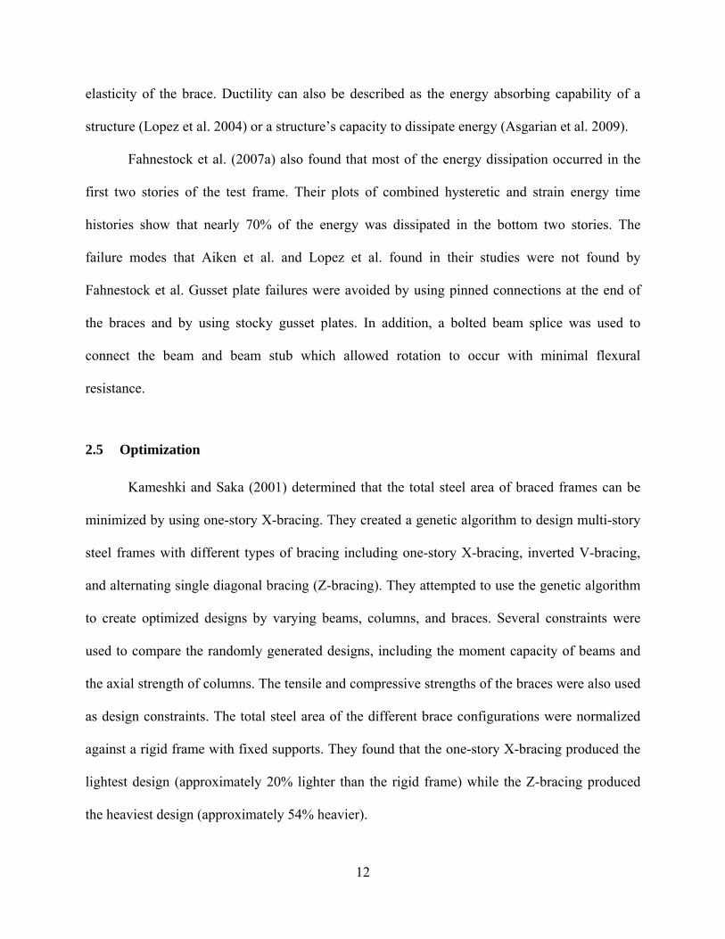
elasticity of the brace. Ductility can also be described as the energy absorbing capability of a
structure (Lopez et al. 2004) or a structure’s capacity to dissipate energy (Asgarian et al. 2009).
Fahnestock et al. (2007a) also found that most of the energy dissipation occurred in the
first two stories of the test frame. Their plots of combined hysteretic and strain energy time
histories show that nearly 70% of the energy was dissipated in the bottom two stories. The
failure modes that Aiken et al. and Lopez et al. found in their studies were not found by
Fahnestock et al. Gusset plate failures were avoided by using pinned connections at the end of
the braces and by using stocky gusset plates. In addition, a bolted beam splice was used to
connect the beam and beam stub which allowed rotation to occur with minimal flexural
resistance.
2.5 Optimization
Kameshki and Saka (2001) determined that the total steel area of braced frames can be
minimized by using one-story X-bracing. They created a genetic algorithm to design multi-story
steel frames with different types of bracing including one-story X-bracing, inverted V-bracing,
and alternating single diagonal bracing (Z-bracing). They attempted to use the genetic algorithm
to create optimized designs by varying beams, columns, and braces. Several constraints were
used to compare the randomly generated designs, including the moment capacity of beams and
the axial strength of columns. The tensile and compressive strengths of the braces were also used
as design constraints. The total steel area of the different brace configurations were normalized
against a rigid frame with fixed supports. They found that the one-story X-bracing produced the
lightest design (approximately 20% lighter than the rigid frame) while the Z-bracing produced
the heaviest design (approximately 54% heavier).

13
Pavlovčič et al. (2004) found that considering fabrication costs in addition to material
costs did not result in significant savings. They compared the optimization of multi-storied steel
frames using conventional volume optimization procedures and detailed cost optimization
procedures. In most structural optimization procedures, the total cost of a structure is estimated
by the volume of steel used in the optimized design. These researchers felt that fabrication costs
such as welding, cutting, and assembly must be considered in addition to material costs to
determine a realistic minimized design. They performed a static analysis incorporating a volume
objective optimization and a total cost objective optimization in addition to a classical design
approach on a two-story, two-bay frame and a four-story, five-bay frame. Both optimizations
resulted in significant savings when compared to the classical design approach. The cost
objective optimization for the two-story structure resulted in savings of just over 25% when
compared to the classical design approach. However, the two optimizations did not produce
significantly different results. The cost objective optimization only provided savings of
approximately 1% compared to the more conventional volume objective optimization.
Liu et al. (2003) had previously studied the effects of additional objectives in addition to
the traditional volume based objective and found that the volume based optimization procedure
was an appropriate design approach for steel frames. Liu et al. performed nonlinear pushover
analyzes of multi-story steel frames with a combination of three different objective functions:
initial material costs, lifetime seismic damage, and erection complexity. They noted that in order
to create construction-conscious designs additional constraints would need to be added to the
optimization procedure.
Hayalioglu, M. and Degertekin, S. (2004) found that frames with semi-rigid connections
generally required less steel than frames which were rigidly connected. The purpose of their

14
study was to analyze semi-rigid connections and account for P-Δ effects of beam-column
members and the nonlinear behavior of connections. They used a genetic algorithm that
accounted for displacement and stress constraints found in AISC-ASD specifications. The results
of their analyzes indicate that a 24% reduction could be made in the costs of a steel frame if the
connections were considered semi-rigid rather than rigid. However, their results also indicate that
a reduction of connection stiffness would lead to an increase in frame sway leading to increased
steel sections.
Balling et al. (2009) produced design tables for BRB areas for frames of differing heights
and widths using the designs created by an optimization program. Analyzes were conducted on
BRBFs of three heights (one-, three-, and five-stories) with bays of multiple heights (10, 12, 14,
and 16ft) and multiple widths (10, 15, 20, 25, 30ft). The frames were subjected to seismic
demands of varying magnitudes and compared the minimized brace areas with those obtained
from using the ELF procedure. The results of the study were used to create design tables that
would allow the user to quickly select braces areas base on the geometry of the braced bays and
the height of the structure without having to conduct the computationally expensive optimization
procedures.
Oxborrow, G. (2009) was able to create multi-story BRBF designs that minimized total
brace area while conforming to ductility and drift constraints which were compared to ELF
designs. Using a genetic algorithm based optimization in OpenSEES, he varied the brace sizes to
produce a optimal design with minimized total brace areas in multi-story BRBFs. The designs
were subjected to ductility and drift constraints. The optimized designs were compared with the
required brace areas computed from the ELF procedure. The brace sizes selected by the genetic
algorithm were generally larger than the braces selected using the ELF method. However, he

15
found that in many cases the braces selected from the ELF method resulted in ductility demands
greater than the ductility capacity implied by the Response Modification and Overstrength
factors.

16

17
3 CURRENT DESIGN PROCEDURES
3.1 Sizing Braces in Buckling-Restrained Braced Frames
The ELF procedure is commonly used for BRBF design. The first step in sizing braces is
determining the brace axial demand, Pu. The brace axial demand, Pu, is found from using the load
combinations and can be calculated using Equation 3-1. In Equation 3-1, Vbrace is the story shear
calculated using the ELF method, Lbrace is the length of the brace, and Bbay is the width of the
brace bay.
)(bay
bracestoryu B
LVP (3-1)
Braces must be sized so that the capacity exceeds the axial demands in the brace as is
shown in Equation 3-2. Braces are sized to have an axial design strength of φPysc where φ is 0.9
and Pysc is defined in Equation 3-3 (Sabelli 2004; AISC 2005). In Equation 3-3, Fysc is the yield
stress of the steel core and Asc is the cross sectional area of the steel core.
uysc PP (3-2)
scyscysc AFP (3-3)

18
3.2 Sizing Columns in Buckling-Restrained Braced Frames
Current code provides two acceptable procedures for designing columns in braced
frames. The first method of designing columns for braced frames directs the designer to
determine the axial force in a column given the calculated base shear and then multiply the
calculated axial force by a factor, Ω0 to determine the column design demand.
The factor, Ω0 is the system’s overstrength factor. Asgarian et al. (2009) describes
overstrength as the reserve strength that the structure possesses. For BRBFs, Ω0 is 2 if the beam-
column connections are not moment resisting, and 2.5 if the beam-column connections are
moment resisting (ASCE 2005).
Fahnestock et al. (2007b) made some interesting observations about the overstrength
factor, Ω0, in their study of a four-story BRBF. For the study, a four-story BRBF was designed
for both the Design Basis Earthquake (DBE) and the Maximum Considered Earthquake (MCE)
(ASCE 2005). Nominally, the DBE is an earthquake event that has a 10% probability of
exceedance in 50 years and the MCE has a 2% probability of exceedance in 50 years. Using the
computer program DRAIN-2DX, they subjected their two-dimensional model of the four-story
BRBF to several ground motions which were scaled to both DBE and MCE seismic hazard
levels. They compared the peak base shear from both the DBE and the MCE with the design base
shear that was calculated using the ELF method. They divided the peak base shear by the design
base shear and compared that normalized value with the code recommended overstrength value
of 2. Their data showed a mean plus standard deviation DBE-level overstrength value of 1.61
and a mean plus standard deviation MCE-level overstrength value of 2.05. They felt that the
results of their study suggest that the recommended overstrength value should be investigated in

19
more detail. If the overstrength value for BRBFs is indeed less than 2, the calculated columns
demands may be too high.
The second column design method directs the designer to determine a theoretical column
demand that is based on the ultimate capacity of the brace, Pult,brace. This method is the preferred
method for designing columns in BRBFs. With this method, the columns will be designed for the
maximum loads that can be delivered from the braces to the columns. The ultimate capacity of a
BRB can be calculated using Equation 3-4. In the following equation, β is the compression factor
that accounts for the difference between the compressive and tensile capacities of a BRB, ω is
the strain hardening factor, and Ry is a material overstrength factor. βωRy is determined from
testing and tends to be around 2.0 (Merrit et al. 2003; Reaveley et al. 2004). For the present study
a value of 2.0 was used for βωRy.
yscscybraceult FARP , (3-4)
After the ultimate capacity of the brace has been computed, the theoretical column
demand can be calculated using Equation 3-5. The theoretical column demand is calculated
assuming that all ductile elements yield and have strain hardened simultaneously. Therefore, for
the remainder of this thesis the theoretical column demand will be referred to Pabh, where “abh”
stands for “all braces hardened”. In Equation 3-5, Pabh, i is the theoretical column demand of the
)(,1,,brace
baybraceultiabhiabh L
HPPP (3-5)

20
column of interest and Pabh, i+1 is the theoretical column demand of the column above. Hbay and
Bbay are the height and width of the braced bay respectively.
Figure 3-1 below illustrates some of the variables from Equation 3-5. As can be seen in
this illustration, Pabh is found by taking the vertical component of the brace ultimate capacity,
Pult,brace and adding it to Pabh of the column above.
Figure 3-1: Calculating Theoretical Column Demands Using the Method of Joints
Pabh, i
Pabh, i+1
Pult, brace
21
4 MODELING
4.1 Frames
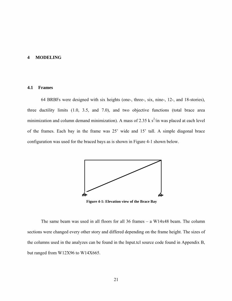
64 BRBFs were designed with six heights (one-, three-, six, nine-, 12-, and 18-stories),
three ductility limits (1.0, 3.5, and 7.0), and two objective functions (total brace area
minimization and column demand minimization). A mass of 2.35 k s2/in was placed at each level
of the frames. Each bay in the frame was 25’ wide and 15’ tall. A simple diagonal brace
configuration was used for the braced bays as is shown in Figure 4-1 shown below.
Figure 4-1: Elevation view of the Brace Bay
The same beam was used in all floors for all 36 frames – a W14x48 beam. The column
sections were changed every other story and differed depending on the frame height. The sizes of
the columns used in the analyzes can be found in the Input.tcl source code found in Appendix B,
but ranged from W12X96 to W14X665.

22
4.2 OpenSEES Materials and Elements
The BRBFs were modeled using a finite element software package called OpenSEES
(Open System for Earthquake Engineering Simulation) (Mazzoni et al. 2006). OpenSEES is an
open source code software package intended for nonlinear time history analysis. While the
beams and columns were modeled as nonlinear beam-column elements, the braces were modeled
using corotational truss elements. Truss elements were used for the braces because the ends were
assumed to be pinned and therefore, the moments at the end of the braces were assumed to be
negligible. A uniaxial steel material, Steel02, was used for all beams, columns, and braces.
Recommendations by Mazzonni et al. (2006) were used for the parameters in the Giuffre-
Menegotto-Pinto equations. Oxborrow, G. (2009) explained that this material, Steel02, allows
the user to consider material hardening properties in conjunction with the previously defined
yield stress and modulus of elasticity. The yield stress of the beams and columns were set as 50
ksi, while the yield stress of the brace was set as 45 ksi.
Because the cross-section of the braces in BRBFs varies along the length, special
techniques must be used to represent the brace with a single element of uniform cross section.
First the length of the yielding portion of the brace must be estimated. Then, the estimated length
of the yielding portion of the brace is used to calculate an equivalent modulus of elasticity.
The steel core of a typical BRB is comprised of three parts- a restrained yielding portion,
a restrained non-yielding portion, and an un-restrained non-yielding portion. The three parts of
the steel core of a typical BRB is illustrated in Figure 4-2.

23
Figure 4-2: The Different Parts of a Steel Core (Lopez 2001. Used without permission)
The length of the yielding portion of the brace in a BRBF can be estimated using various
methods. In a series of analyzes conducted by Lopez et al. (2004), the length of the yielding
portion of the brace was assumed to be two-thirds of the total length of the brace. For the
purposes of this study, the length of the yielding portion of the BRB was calculated using
Equations 4-1 and 4-2 (Oxborrow 2009). In the following equations, L1 is the total brace length
measured from the centerlines of the beam-column intersections and L2 is the length of the non-
yielding portion of the brace. θ is the angle of brace measured from a plane parallel to the beam.
Equation 4-1 attempts to account for the restrained non-yielding portion of the brace by reducing
the yielding length of the brace by 15%.
)2(85.0 21, LLL yieldBRB (4-1)
"24sin2
beamd
L (4-2)
In order to account for the varying cross-sectional area of the BRB, the modulus of
elasticity needed to be adjusted. In a typical BRB, the cross section area of the steel core does not

24
remain constant throughout the entire length. The restrained yielding core is typically has a
smaller cross sectional area than the non-yielding portions of the BRB. In order to properly
account for the varying cross sectional area of the steel core, an equivalent modulus of elasticity
was calculated using Equation 4-3. In this equation, L1 is the total length of the steel core and
LBRB,Yield is the length of the yielding portion of the steel core as was shown previously in
Equation 4-1.
yieldBRB
braceequiv L
LEE
,
1 (4-3)
4.3 Ground Motions
Nonlinear time history analyzes were used in conjunction with the optimization program
to create optimized BRBF designs. Two earthquake ground motions were used in this study. The
response spectra for the earthquakes used in this study are show in Figure 4-3. The first
earthquake ground motion used was from the 1979 Imperial Valley Earthquake El Centro Array
#4. This ground motion had a maximum spectral acceleration of 0.85g for a damping ratio of 5%
(See Figure 4-3). The closest point to fault rupture was 4.2 km and the closest point to the
surface projection of the rupture was 6.8 km. The soils at this site are classified as USGS Site
Class C. In later plots, the responses of the BRBFs to this ground motion are labeled H-E04230.
The time histories for this and the other earthquake ground motion used in this study were
obtained from the Pacific Earthquake Engineering Record (PEER).
The second earthquake ground motion used was from the 1989 Loma Prieta Earthquake.
The ground motion was recorded at the Hollister City Hall and the closest point to fault rupture

25
was 28.2 km. For damping ratio of 5%, the response spectra had a maximum spectral
acceleration of 0.706g (See Figure 4-3). The soils at this site are classified at USGS Site Class C.
In later plots, the responses of the BRBFs to this earthquake ground motion are labeled HCH180.
The magnitudes of the spectral accelerations are less important than the shape of the
spectra for the present study. The purpose of this study is to investigate the relationship between
designs optimized for total brace area and designs optimized for base column demands. The
results that are discussed are generally normalized such that the magnitudes are less important to
the conclusions. The two earthquake ground motions used in this study represent fairly different
types of demands.
0.00
0.20
0.40
0.60
0.80
1.00
1.20
0.00 1.00 2.00 3.00 4.00 5.00
P eriod, T (s ec )
Spectral Acceleration (g)
H‐E 04230 HC H180
Figure 4-3: Response Spectra of Earthquake Ground Motions Used

26

27
5 OPTIMIZATION PROCEDURE
Genetic algorithm based optimization procedures were used in this study. Genetic
algorithms, sometimes referred to as evolutionary optimization, use the idea of “survival of the
fittest” to create an optimized design based on parameters of the users’ choosing. Genetic
algorithms use a process of selection, mating, crossover, mutation, and sorting to create various
designs. Then criteria are applied to determine which designs are the “fittest”. The fittest designs
are used to produce the next generation of designs. These evolutionary computations imitate
biological evolution to create an optimized, or in other words, a minimized design.
This study developed optimized designs using two different objective functions. The first
objective function was minimizing the total brace area of the multi-story BRBF. The second
objective function was minimizing the demands in the first story columns. The results from the
two optimization procedures were compared to see in what ways the optimum designs differed.
The genetic algorithm begins by randomly selecting design variables to create nsize
number of designs to create a generation. The total number of generation created, ngener, varied
for the different height frames. A summary of the optimization inout parameters can be found in
Table 5-1. The value for nsize was 50 for all of the frames analyzed in this study. The design
variable used in this study was the area of the brace in square inches. The brace sizes were
randomly selected using a random integer generator from a list of braces areas. The list of brace
areas started at 1in2 and increased at increments of 0.5in2 until 6in2 and then increased at

28
increments of 1in2 until 30in2. The brace areas for the different levels were selected independent
of one another.
The randomly created designs were then subjected to a ground motion and the BRBF
response in terms of brace deformation was recorded. The earthquake ground motions that were
used were presented in the previous section 4.3 Ground Motions. The deformations of each of
the braces under the earthquake ground motions were recorded at each time step and the
maximum deformation was noted. The maximum brace deformation was later used to determine
the ductility demand at each story.
Each design was then examined and assigned a fitness level by comparing the BRBF
response to the specified ductility constraints. The ductility at each level was calculated using the
recorded max brace deformation and dividing it by the brace elastic deformation. The calculated
ductility at each level was then compared with specified ductility constraints. In this study, three
ductility constraints were considered: 1.0, 3.5, and 7.0. A ductility of 3.5 is similar to that
implied by a Response Modification Factor, R, of 7.0 and an Overstrength Factor, Ω0 of 2.0. The
relationship between ductility, R, Ω0 and is shown in Equation 5-1.
0 RDuctility (5-1)
The ductility constraint is summarized in Equation 5-2 which is shown on the following
page. In this equation, μmax is the maximum ductility demand at a story and μallow is the allowable
ductility. μmax was calculated using Equations 2-2 and 2-3 and μallow was set as 1.0, 3.5, or 7.0.
For the purposes of this study, the goal of the optimization was to minimize the column axial

29
demand, Faxial, in the main level column or minimize the total brace area while satisfying the
ductility constraint shown below.
allow
allow
max (5-2)
In order to assign a design a fitness value, the feasibility of the design must first be
calculated. The feasibility of a design, g, is determined by taking the maximum of 0 and
Equation 5-2. If g > 0 then the design is infeasible; if g = 0 the design is feasible.
For this study, the fitness of each design was calculated using a segregation approach. In
this approach, all of the feasible designs (those designs where g = 0) are assigned a fitness equal
to f, where f is the function that we are trying to minimize. In this study, f was the total brace area
or base column demand in the main floor column. In order to assign a fitness value to the
infeasible designs (those designs where g > 0), one must find the highest value for f from among
the feasible designs of that generation. The fitness for an infeasible design is then calculated by
adding the feasibility, g, to the maximum value for f from the feasible designs. This ensures that
an infeasible design does not have a lower fitness value than a feasible design. The segregation
approach is summarized below in Equation 5-3 (Balling 2006). In order to ensure the “fittest”
designs are used for future generations, the infeasible designs are punished and are given a
higher fitness values.
0
0
max,
gifgf
gifffitness
feasible
(5-3)

30
After the designs in a generation have been analyzed and assigned a fitness value, a
selection process takes place to create a new generation. Using a random number generator,
ntourn number of designs are randomly selected to potentially be “mothers” and “fathers” to the
next generation. For all frames analyzed a tournament size of six was used. The fitness values of
the randomly selected designs are compared and the most “fit” designs, designs with the lowest
fitness values, become the parents to two new children designs.
Through a process of crossover and mutation, nsize children designs are created. The new
nsize designs and the nsize designs from the previous generation are combined and sorted by
fitness values. The nsize “fittest” designs are then used to create a new generation. This process
is repeated ngener-1 number of times resulting in an optimized design.
The probability that crossover would occur was dictated by probcross which was set as
0.6 for all frames used in this study. Crossover of designs would only occur if a randomly
selected number between zero and one was less than probcross. Because the design variables in
this study were discrete design variable, a uniform crossover method was used. For a given
study, the brace sized of the child designs would be switched if the randomly selected number
was less than probcross.
The optimization program used a uniform mutation method to perform mutation of child
designs. A value of 0.1 was used for probmutate. Just like with crossover, the program randomly
generated a number between zero and one. If the randomly generated number was less than
probmutate, mutation would occur. The child designs were mutated by replacing the current
brace in the child design with a new randomly generated brace size. Table 5-1 summaries the
input parameters used for the different height frames.

31
Table 5-1: Optimization Procedure Parameters
nsize ngener ntourn probcross probmutate1 50 50 6 0.6 0.13 50 100 6 0.6 0.16 50 500 6 0.6 0.19 50 500 6 0.6 0.112 50 500 6 0.6 0.118 50 500 6 0.6 0.1
Number of Stories
Parameter

32

33
6 DISCUSSION OF RESULTS
A total of 64 frames were developed in this study and the resulting brace areas and
column demands of the base level columns were compared. At each level, the required brace
area and brace deformation was recorded and the brace ductility was calculated. In addition, the
maximum axial force in the first story column was recorded for each analysis. The total brace
areas and column demands from the various analyzes were compared and will be discussed in
the following sections. Table 6-1 shows all of the 64 frames that were analyzed in this study.
Table 6-1: Summary of Frames Designed
1.0 3.5 7.0HCH180 Total Brace Area HCH180 Base Column Demand
H-E04230 Total Brace Area H-E04230 Base Column Demand HCH180 Total Brace Area HCH180 Base Column Demand
H-E04230 Total Brace Area H-E04230 Base Column Demand HCH180 Total Brace Area HCH180 Base Column Demand
H-E04230 Total Brace Area H-E04230 Base Column Demand HCH180 Total Brace Area HCH180 Base Column Demand
H-E04230 Total Brace Area H-E04230 Base Column Demand HCH180 Total Brace Area HCH180 Base Column Demand
H-E04230 Total Brace Area H-E04230 Base Column Demand HCH180 Total Brace Area HCH180 Base Column Demand
H-E04230 Total Brace Area H-E04230 Base Column Demand
Number of Stories
Ductility Limit
1
3
6
Objective Funtion
9
12
18
EQ Used

34
6.1 Comparison of Normalized Brace Areas
In general, the objective function that minimized the total brace area resulted in lighter
designs and would be expected. Both objective functions used brace area as the design variable,
and the resulting total brace areas from the two analyzes were compared. As can be seen in Table
6-2, the program that minimized the brace areas produced designs that had smaller average brace
sizes when compared to the program that minimized the column demand in the first floor
columns.
Table 6-2: Comparison of Average Brace Areas with Allowable Ductility of 3.5
Number of Stories
Area Optimization
Base Col Demand
OptimizationDifference (%)
1* 2.00 11.00 81.821** 1.50 1.50 0.003* 3.33 3.33 0.003** 4.00 16.67 76.006* 3.58 7.42 51.696** 5.67 10.83 47.699* 4.33 7.50 42.229** 7.39 10.94 32.4912* 1.09 1.68 35.1412** 8.23 11.59 29.0218* 1.06 4.36 75.8018** 8.69 11.61 25.12
* HCH180**H-E04230
Average Brace Area (in2)
Figures 6-1 through 6-4 show the brace areas plotted at each story for the optimized
designs produced by both the total area objective function and the base column demand objective
function. As was discussed previously, the designs produced by the minimized total brace
objective function were lighter. In addition, the minimized total brace area objective function

35
produced designs with brace seizes that increased linearly down the height of the frame. This
linear distribution of brace sizes is illustrated in Figures 6-1 through 6-4.
The designs produced by the objective function that minimized base column demand also
had brace sizes that varied linearly along the height of the frame except for a brace at one of the
top one or two stories that was drastically larger than the other braces. Other than the large brace
in the top one or two stories in the minimized base column demand designs, the brace sizes
produced by the two objective functions were essentially the same.
In observing the plots of the brace sizes (Figures 6-1 through 6-4), it appears that the
brace sizes in the lower stories are unaffected by the objective function. Whether minimizing the
total brace area or the base column demands, the brace areas in the optimized designs were
essentially the same in the lower stories. However, the same cannot be said about the braces in
the higher stories. Given the results from the analyzes one can conclude that brace sizes cannot
be minimized when using an objective function that minimizing the base column demand. The
minimized base column demand objective lead to designs that had extremely large braces in the
top few stories.
The difference between the designs produced by the base column demand objective
function and the total brace area function can be attributed to the differing goals of the two
optimization functions. When minimizing the total brace area, the program chooses brace sizes
that minimize the total brace area while satisfying the given constraints. However, when the
program is directed to minimize the column demands in the first story column, the program pays
no attention to what is happening to the brace area. The program’s only goal is to minimize the
axial demands by changing the brace sizes without violating the given constraints. The design
with the larger brace size meets the ductility requirements and minimizes base column demands.

36
1
2
3
0 5 10 15 20 25 30
Brace Area (in2)
Sto
ry
Area HCH180
Col Demand HCH180
Area H-E04230
Col Demand H-E04230
Figure 6-1: Brace Areas for a Three-Story BRBF (Ductility Limit of 3.5)
1
2
3
4
5
6
0 5 10 15 20 25 30
Brace Area (in2)
Sto
ry
Area HCH180
Col Demand HCH180
Area H-E04230
Col Demand H-E04230
Figure 6-2: Brace Areas for a Six-Story BRBF (Ductility Limit of 3.5)

37
1
2
3
4
5
6
7
8
9
0 5 10 15 20 25 30
Brace Area (in2)
Sto
ry Area HCH180
Col Demand HCH180
Area H-E04230
Col Demand H-E04230
Figure 6-3: Brace Areas for a Nine-Story BRBF (Ductility Limit of 3.5)
1
3
5
7
9
11
0 5 10 15 20 25 30
Brace Area (in2)
Sto
ry
Area H-E04230
Col Demand H-E04230Area HCH180
Col DemandHCH180
Figure 6-4: Brace Areas for a 12-Story BRBF (Ductility Limit of 3.5)

38
As was previously discussed, the brace areas appear to increase linearly moving down the
structure in the frames that were subjected to a minimized total brace area objective function. A
normalized brace area was found by dividing the brace area at a particular story by the average
brace area. A closer inspection of the normalized brace areas reveals that the top brace was
approximately 0.5 times the average brace size and the bottom brace was 1.5 times the average
brace size. These results are consistent with those from Balling et al. (2007). The design charts
that were created for sizing braces in BRBFs show a linear distribution of brace areas increasing
moving down the height of a multi-story frame. The normalized brace areas that were found
ranged from 0.5 in the top stories to 2.0 in the lower stories for the three- and five story frames
that were optimized.
This linear distribution of normalized brace areas found in this study is illustrated in
Figures 6-5 through 6-8. These figures plot the normalized brace area at each story for both
optimization types with the area and column demand optimizations shown in solid and dashed
lines respectively. A thick dashed line has been added to show the linear distribution of brace
sizes from 0.5 at the top story to 1.5 at the bottom story. Figures 6-5 through 6-8 are for frames
designed with a ductility constraint of 3.5. The plots for frames designed with ductility
constraints of 1.0 and 7.0 can be found in Appendix A.

39
1
2
3
0 1 2 3
Normalized Brace Area
Sto
ry
Area HCH180
Col Demand HCH180
Area H-E04230
Col Demand H-E04230
Figure 6-5: Normalized Brace Distribution for a Three-Story BRBF (Ductility Limit of 3.5)
1
2
3
4
5
6
0 1 2 3
Normalized Brace Area
Sto
ry
Area HCH180
Col Demand HCH180
Area H-E04230
Col Demand H-E04230
Figure 6-6: Normalized Brace Distribution for a Six-Story BRBF (Ductility Limit of 3.5)

40
1
2
3
4
5
6
7
8
9
0 1 2 3
Normalized Brace Area
Sto
ryArea HCH180
Col DemandHCH180Area H-E04230
Col Demand H-E04230
Figure 6-7: Normalized Brace Distribution for a 9-Story BRBF (Ductility Limit of 3.5)
1
3
5
7
9
11
0 1 2 3
Normalized Brace Area
Sto
ry
Area H-E04230
Col Demand H-E04230Area HCH180
Col DemandHCH180
Figure 6-8: Normalized Brace Distribution for a 12-Story BRBF (Ductility Limit of 3.5)

41
The linear distribution of normalized brace areas shown in Figures 6-5 through 6-8
provides a simple, yet effective starting point for selecting brace sizes in BRBF. When
performing any type of analysis or structural optimization, initial brace sizes must be selected
before beginning. By understanding that the optimized design for multi-story BRBF displays a
linear distribution of brace sizes would help in selecting those initial brace sizes need for analysis
and optimization.
Both analyzes conducted on the 18-story BRBF produced results that somewhat differed
from the other frames analyzed. Figure 6-9 shows the braces sizes plotted at each level for an 18-
story BRBF with a ductility limit of 3.5. Generally, the size of the braces in the 18-story BRBF
did increase towards the bottom of the structure. However, the bottom half of the structure shows
a zigzag pattern in the size of the braces as seen in Figure 6-9. In all of the other height frames,
the area of the brace below was generally smaller than the brace above. Oxborrow (2009)
observed the same zigzagging pattern in his plots of normalized braced areas for 18-story
BRBFs. The zigzagging pattern may indicate that the genetic algorithm was unable to converge
to an optimum design. Due to the height of the 18-story frame and the number of design
variables, the search area for the genetic algorithm becomes extremely large. This large search
area may hinder the genetic algorithm from finding the true optimum design. The zigzagging
pattern may also indicate that there are multiple local minima for the frame of interest. Further
study is required to determine why the brace sizes do not increase linearly as was seen in the
other height models.

42
1
3
5
7
9
11
13
15
17
0 5 10 15 20 25 30
Normalized Brace Area
Sto
ry Area H-E04230
Col Demand H-E04230
Area HCH180
Col Demand HCH180
Figure 6-9: Brace Areas for an 18-Story BRBF (Ductility Limit of 3.5)
Figures 6-10 and 6-11 show the normalized brace areas for a 12-story BRBF with a
ductility limit of 7.0 and 3.5 respectively. All other plots of normalized brace areas with a
ductility limit of 7.0 can be found in section A.2 of Appendix A. As was seen in the plots of
normalized brace areas in frames with a ductility limit of 3.5, the normalized brace area plots for
frames with a ductility limit of 7.0 display a linear distribution of brace sizes. This linear
distribution of brace sizes also start at 0.5 for the top story and increases to 1.5 at the base story.
In the plots of the frames that had a ductility limit of 7.0, the zigzagging pattern of braces areas
in the lower stories became more pronounced. In addition, the large brace areas that were
observed in the plots for the minimized base column demand (Figures 6-5 through 6-8) were
observed in the plots for frames with a ductility limit of 7.0.
Figure 6-12 shows the normalized brace area plot for a 12-story BRBF with a ductility
limit of 1.0. Additional normalized brace area plots for frames with a ductility limit of 1.0 can be

43
found in section A.1 of Appendix A. Unlike Figures 6-10 and 6-11, the plot of normalized brace
areas in Figure 6-12 does not show a linear distribution. Instead, the plots tends to display more
of a curved shape at the lower storied. These results are supported by work previously done by
Oxborrow, G. (2009). Figure 6-12 resembles normalized brace area plots for frames designed
using the ELF method. The normalized brace area plots for the designs produced using the ELF
method did not show a linear distribution of brace sizes.
1
3
5
7
9
11
0 1 2 3
Normalized Brace Area
Sto
ry
Area H-E04230
Col Demand H-E04230
Figure 6-10: Normalized Brace Distribution for a 12-Story BRBF (Ductility Limit of 7.0)

44
1
3
5
7
9
11
0 1 2 3
Normalized Brace Area
Sto
ry
Area H-E04230
Col Demand H-E04230Area HCH180
Col DemandHCH180
Figure 6-11: Normalized Brace Distribution for a 12-Story BRBF (Ductility Limit of 3.5)
1
3
5
7
9
11
0 0.5 1 1.5 2 2.5 3
Normalized Brace Area
Sto
ry
Area H-E04230
Col Demand H-E04230
Figure 6-12: Normalized Brace Distribution for a 12-Story BRBF (Ductility Limit of 1.0)

45
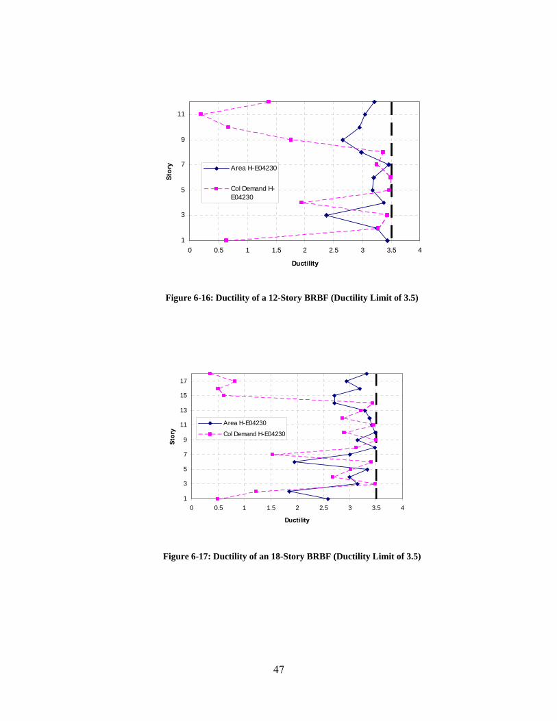
6.2 Comparison of Ductility Demands
In all 64 analyzes, the ductility constraint governed the design of the braces in the
BRBFs, and the area optimization produced designs that controlled the ductility constraints.
Figures 6-13 through 6-17 show the ductility of the brace at each level for designs with a
ductility constraint of 3.5. The area optimization produced designs that were controlled by the
ductility constraint of 3.5 in all of the analyzes. Figure 6-15, particularly illustrates how closely
the constraint of ductility was satisfied. Similar plots for a ductility limit of 1.0 and 7.0 can be
found in Appendix A.
1
2
3
0 0.5 1 1.5 2 2.5 3 3.5 4
Ductility
Sto
ry
Area HCH180
Col Demand HCH180
Area H-E04230
Col Demand H-E04230
Figure 6-13: Ductility of a Three-Story BRBF (Ductility Limit of 3.5)
The column demand optimization produced designs that that did not come close to the
ductility constraints at every story. In Figures 6-14 through 6-17, the ductility of the upper story
braces is shown to be less than one. A ductility of less than one suggests that the maximum
deformation is less than the expected brace deformation when the brace yields. Because the

46
maximum deformation is less than the elastic, or yield deformation, we know that the braces in
the upper stories of these taller BRBFs are not yielding.
1
2
3
4
5
6
0 0.5 1 1.5 2 2.5 3 3.5 4
Ductility
Sto
ry
Area HCH180
Col Demand HCH180
Area H-E04230
Col Demand H-E04230
Figure 6-14: Ductility of a Six-Story BRBF (Ductility Limit of 3.5)
1
2
3
4
5
6
7
8
9
0 0.5 1 1.5 2 2.5 3 3.5 4
Ductility
Sto
ry Area HCH180
Col Demand HCH180
Area H-E04230
Col Demand H-E04230
Figure 6-15: Ductility of a Nine-Story BRBF (Ductility Limit of 3.5)
47
1
3
5
7
9
11
0 0.5 1 1.5 2 2.5 3 3.5 4
Ductility
Sto
ry Area H-E04230
Col Demand H-E04230
Figure 6-16: Ductility of a 12-Story BRBF (Ductility Limit of 3.5)
1
3
5
7
9
11
13
15
17
0 0.5 1 1.5 2 2.5 3 3.5 4
Ductility
Sto
ry
Area H-E04230
Col Demand H-E04230
Figure 6-17: Ductility of an 18-Story BRBF (Ductility Limit of 3.5)

48
6.3 Comparison of Column Demands
In both types of optimization procedures, the results show in general column demands
decreased each generation. Figures 6-18 and 6-19 show the total brace area and axial demands
plotted at the end of each generation for a six-story BRBF. This same general trend was observed
in all frames analyzed.
In Figure 6-18, there is a sudden increase in the total brace area in the column demand
optimization around generation 50. However, Figure 6-19 shows that the column demands
continued to decrease even as the total brace area increased. This sudden increase of total brace
area can be attributed to the one very large brace in the top story of the nine-story BRBF. As can
be seen in Figures 6-18 and 6-19, large braces in the higher stories do not affect column demands
in the lower stories.
0
10
20
30
40
50
60
70
80
90
100
0 100 200 300 400 500
Generation
To
tal
Bra
ce A
rea,
in
2
Area HCH180
Col Demand HCH180
Figure 6-18: Total Brace Area vs Generation for a Six-Story BRBF (Ductility Limit of 3.5)

49
0
200
400
600
800
1000
1200
1400
1600
1800
2000
0 100 200 300 400 500
Generation
Bas
e C
olu
mn
Dem
and
, k
Area HCH180
Col Demand HCH180
Figure 6-19: Base Column Demand vs Generation for a Six-Story BRBF (Ductility Limit of 3.5)
A comparison of the axial demands in the first story columns at the end of the area and
column demand optimizations showed insignificant differences. As can be seen in Table 6-3, the
force optimization often led to a lower column demand than the area optimization as might be
expected. The difference in the columns demands was greatest for the six-story BRBF but still
was less than a 10% difference. The designs produced for the 12- and 18-story frames using the
HCH180 earthquake ground motion has base column demand differences of 10 to 20%. These
designs may not adequately show the relationship between brace size and base column demand.
The spectra accelerations for the range of periods for the taller frames were extremely small. The
optimized designs had a brace area of 1 in2 for most stories. The 1 in2 brace was the smallest
brace the optimization program was allowed to select. If the optimization program was able to
choose smaller braces, we would have seen that base column demands in the designs produced
by the two objective functions would have been essentially the same.

50
Table 6-3: Comparison of the Maximum Axial Demands (Ductility Limit of 3.5)
Number of Stories
Area Optimization
Base Col Demand
OptimizationDifference (%)
1* 83.69 81.27 -2.981** 70.14 70.14 0.003* 388.05 388.05 0.003** 458.91 434.69 -5.576* 815.33 765.70 -6.486** 1276.13 1250.22 -2.079* 1274.89 1232.47 -3.449** 2444.31 2504.39 2.4012* 392.59 489.19 19.7512** 3776.20 3841.16 1.6918* 537.30 481.18 -11.6618** 5581.16 5699.98 2.08
* HCH180**H-E04230
Maximum Base Column Demand (k)
It is interesting to note that in the 12- and 18-story BRBFs, the force optimization
converged to an optimal design that had a greater axial column demand than the minimized brace
area design. This difference was small (approximately 2%) and can be attributed to the large
braces in the higher stories.
The results show that column demands and brace areas are closely related in the bottom
stories. The results also indicate that base column demands can be minimized by using and
objective function that minimizes total brace area. In addition, the results showed that large
braces in the higher stories did not have a large effect on the column demands at the base of the
frame.

51
6.4 Comparison of Design Column Demands and Actual Column Demands
Given the brace sizes selected by the two optimization procedures, a maximum
theoretical column demand was calculated and compared to the actual demands. Actual demands
referrs to the maximum base column demand that was found from the analyzes. The maximum
theoretical column demands were calculated using the second design method discussed in
Section 3.2 Sizing Columns in Buckling Restrained Braced Frames. As was previously
explained, the maximum theoretical column demand is calculated assuming that all ductile
elements yield and strain harden at the same time.
In all of the frames, the maximum base column demand found in the non-linear time
history analysis, Puth, did not reach the maximum theoretical column demand, Pabh. Tables 6-4
and 6-5 show the maximum theoretical demand, Pabh, and the actual demands from the time
history analyzes, Puth, for the designs produced by the total brace area objective function and the
base column demand objective function respectively.
Table 6-4: A Comparison of Pabh and Puth Using Total Brace Area Optimization (Ductility Limit of 3.5)
Number of Stories
Theoretical Demand, Pabh (k)
Actual Demand, Puth (k)
Pu/Pabh
1* 94.67 83.69 0.881** 71.00 70.14 0.993* 473.34 388.05 0.823** 568.00 458.91 0.816* 1017.67 815.33 0.806** 1609.34 1276.13 0.799* 1846.01 1274.89 0.699** 3147.69 2444.31 0.7812* 639.00 392.59 0.6112** 4899.03 3776.20 0.7718* 899.34 537.30 0.6018** 7407.71 5581.16 0.75
* HCH180**H-E04230

52
For the designs produced using the total brace area minimizing function, the ratio of the
actual demand and theoretical demand is always less than 1.0 (See Table 6-4). The difference
between Puth and Pabh is more pronounced in the taller frames. Puth was only 61 to 79% of Pabh.
This same result for taller frames was observed by Richards (2009) in his study of column
demands in BRBFs.
In the designs created by the base column demand objective function, Puth was always
less than Pabh as was seen in the frames designed with an objective function of minimizing the
total brace area. However, the difference between Puth and Pabh is more extreme when
minimizing the base column demand is the objective function (See Table 6-5).
Table 6-5: A Comparison of Pabh and Puth Using Column Demand Optimization (Ductility Limit of 3.5)
Number of Stories
Theoretical Demand, Pabh (k)
Actual Demand, Puth (k)
Pu/Pabh
1* 520.67 81.27 0.161** 71.00 70.14 0.993* 473.34 388.05 0.823** 2366.68 434.69 0.186* 2106.35 765.70 0.366** 3076.69 1250.22 0.419* 3195.02 1232.47 0.399** 4662.36 2504.39 0.5412* 1041.34 489.19 0.4712** 7407.71 3841.16 0.5218* 3715.69 481.18 0.1318** 9892.72 5699.98 0.58
* HCH180**H-E04230
As was explained in Section 3.2 Sizing Columns in Buckling-Restrained Braced Frames,
Pabh is based on the brace area. As brace area increases, the ultimate capacity of the brace,
Pult,brace, increases which increases Pabh. The frames which we designed using the base column

53
objective function had very large braces in the higher stories. These larger brace sizes led to
large values for Pabh and a greater difference between Pabh and Puth.
It is clear that it is overconservative to use Pabh for column and foundation design. A
simple method for computing base column demands that more accurately match the actual
column demands would be very helpful. The results of this study indicate that the brace sizes in
the upper stories do not impact the base column demands. The question to be answered is “How
many stories do impact the base column demands?”
Using the brace areas from the optimization procedures, the theoretical maximum column
demand for each story, Pabh was calculated from the ground level up. The cumulative theoretical
column demand was calculated at each level and then compared with the base column demand,
Puth, from the analysis. Once the cumulative theoretical column demand exceeded Puth, Pabh of
the rest of the stories was ignored.
Table 6-6 shows the story where the cumulative Pabh exceeded Pu for the different height
frames. In the taller frames, the braces in the upper stories were not needed to contribute to the
cumulative Pabh. The cumulative Pabh of the lower stories was enough to exceed Puth.
Table 6-6: Story Where Cumulative Pabh Exceeds Puth (Ductility Limit of 3.5)
Number of Stories
Story Where Cumulative ΣPabh>Puth
1* 1st1** 1st3* 3rd3** 3rd6* 5th6** 4th9* 5th9** 6th12* 7th12** 8th18* 11th18** 12th
* HCH180**H-E04230

54
As an example, we will look at the nine-story frame that was designed with the total
brace area objective function and the earthquake ground motion H-E04230. The actual column
demand, Puth, was 2444.31 k. The brace area in the first story was 11.0 in2. Using Equation 3-4,
an ultimate brace capacity of 986.7 k was calculated. The vertical component of the brace
ultimate capacity, Pult,brace yields a result of 986.7 k for Pabh.
The brace area in the second story was 10.0 in2. Pul,bracet and Pabh are 897 k and 461.5 k
respectively for a 10.0 in2 brace. The cumulative Pabh for the first two stories was 969.16 k. This
same procedure was repeated for every story until the cumulative Pach (ΣPabh) was greater than
Puth. A summary of this example can be found in Table 6-7.
The calculated values in Table 6-7 show that the top three braces are not needed to ensure
that the Pach at the base story is greater than Pu. The vertical component of the ultimate capacities
of the braces in the six stories results in ΣPabh greater than Pu.
Table 6-7: Summary of the Nine-Story BRBF Example
Story Areaused Pult,brace (k) Pabh ΣPabh
1 11.0 1012.00 520.67 520.672 10.0 920.00 473.34 994.013 10.0 920.00 473.34 1467.344 9.0 828.00 426.00 1893.345 8.0 736.00 378.67 2272.016 7.0 644.00 331.34 2603.357 5.5 506.00 260.33 2863.688 4.0 368.00 189.33 3053.029 2.0 184.00 94.67 3147.69
Puth= 2444.31 k
The procedure previously explained and described in the example problem was repeated
for all frames that were designed with a ductility limit of 3.5. The number of stories needed was

55
normalized by dividing by the total number of stories in the frame. Therefore, a value of 1.0
implies that all of the stories were needed for ΣPabh to be greater than Puth. The normalized
values were plotted against the total number of stories and are shown in Figure 6-20. The dashed
line represents designs created using the earthquake ground motion H-E04230 and the total brace
area objective function. The solid line represents designs produced from the HCH180 ground
motion and the total brace area objective function.
Figure 6-20 shows that for shorter frames, Pabh is close to Puth and all of the braces are
needed. However, with taller frames, Pabh is much larger than Puth. The braces in the upper
stories are not needed to calculate a ΣPabh value that is greater that Puth. Once the height of the
frame exceeds six stories, only two-thirds of the braces are needed for Pabh.
0
0.5
1
1.5
2
0 3 6 9 12 15 18
Number of Total Stories
Sto
ry W
her
e Σ
Pa
bh>P
uth/T
ota
l Nu
mb
er o
f S
tori
es
HCH180
H-E04230
Figure 6-20: Linear Relationship Between the Total Number of Stories and the Number of Stories of Braces Required to Produce the Actual Column Demand

56
The results shown in Figure 6-20 provide a simple method for more accurately
determining the load that columns and foundations should be designed for. Instead of designing a
column for Pabh based on the ultimate capacities of all of the braces, Figure 6-20 indicates that
only the bottom two-thirds of all the braces need to be considered. Therefore, a theoretical base
column demand can be calculated using the ultimate capacities of only the braces in the bottom
two-thirds of the multi-story frame. This will result in a theoretical base column demand
approximately equal to Puth.

57
7 SUMMARY AND CONCLUSIONS
Nonlinear time history analyzes were conducted on buckling-restrained braced frames of six
heights. Optimized results were found considering three ductility constraints and two
optimization objectives. The two optimization objectives were minimized total brace area and
minimized base column demands. The total brace areas and column demands from the two
optimization procedures were compared to investigate the relationship between brace sizes and
base column demands. Conclusions from the analyzes are as follows:
1. Minimizing for total brace area produced lighter braces than minimizing for base
column demands. For the shorter frames, the average brace areas for a minimized
brace area objective were approximately 50% of the average braces areas from the
base column demand objective. In the taller frames, the difference between the
average brace areas from the two objectives was only 25%. The ductility of the
braces in the designs for brace area optimization hovered near the specified
ductility limit.
2. Normalized brace area plots provide a simple yet effective starting point for
selecting brace sizes.
3. Minimizing the base column demand did not result in significantly lower base
column demand than minimizing for total brace area. While minimizing base
column demand did generally produce designs with lower column demands, the
difference in the most extreme case was approximately 10%.

58
4. If the large, oversized braces in the higher stories of the column demand analyzes
were ignored, the two optimization types produce nearly identical designs.
5. Base column demands can be minimized by minimizing the brace areas.
However, brace areas cannot be minimized by minimizing base column demands.
6. The base column demands from the time history analyzes, Puth were much smaller
than the theoretical maximum column demands, Pabh. For the nine-story and taller
frames, the braces in the top third could be ignored when estimating base column
demands.

59
REFERENCES
Aiken, I., P. Clark, and F. Tajirian. “Unbonded Braces in the United States-Design Studies, Large-scale Testing and the First Building Application.” Japan Passive Control Symposium. Tokyo, Japan, 2000.
Aiken, I. D., S. A. Mahin, and P. Uriz. “Large-Scale Testing of Buckling-Restrained Braced
Frames.” Japan Passive Control Symposium. Tokyo, Japan, 2002. American Institute of Steel Construction (AISC). AISC 341, Seismic Provisions for Structural
Steel Building. Chicago, IL: American Institute of Steel Construction Inc., 2005. American Society of Civil Engineers (ASCE). ASCE 7-05, Minimum Design Loads for Buildings
and Other Structures. Reston, VA: American Society of Civil Engineering, 2005. Asgarian, B., and H. R. Shokrgozar. “BRBF Response Modification Factor.” Journal of
Construction Steel Research 65 (2009): 290-298. Balling, R. J. Computer Analysis and Optimization of Structures. Provo, UT: Brigham Young
University Academic Publishing, 2006. Balling, R. J., L. J. Balling, and P. W. Ricahrds. “Design of Buckling-Restrained Braced Frames
Using Nonlinear Time History Analysis and Optimization.” Journal of Structural Engineering 135, no. 5 (2009): 461-468.
Eryaşar, M. E., and C. Topkaya. “An Experimental Study on Steel-Encased Buckling-Restrained
Brace Hysteretic Dampers.” Earthquake Engineering and Structural Dynamics 39 (2010): 561-581.
Fahnestock, L. A., J. M. Ricles, and R. Sause. “Experimental Evaluation of a Large-Scale
Buckling-Restrained Braced Frame.” Journal of Structural Engineering 133, no. 9 (2007a): 1205-1214.
Fahnestock, L. A., R. Sause, and J. M. Ricles. “Seismic Response and Performance of Buckling-
Restrained Braced Frames.” Journal of Structural Engineering 133, no. 9 (2007b): 1195-1204.

60
Fujimoto, M., A. Wada, E. Saeki, A. Watanabe, Y. Hitomi. “A Study on the Unbonded Brace Encased in Buckling-Restraining Concrete and Steel Tube.” Journal of Structural Engineering 34B (1988): 249-258.
Hayalioglu, M. S., and S. O. Degertekin. “Design of Non-linear Steel Frames for Stress and
Displacement Constraints with Semi-rigid Connections Via Genetic Optimization.” Structural and Multidisciplinary Optimization 27 (2004): 259-271.
International Code Council (ICC). (2006). International Building Code, Whittier, CA. Kameshki, E. S., and M. P. Saka. “Genetic Algorithm Based Optimum Bracing Design of Non-
Swaying Tall Plane Frames.” Journal of Construction Steel Research 57 (2001): 1081-1097.
Koboevic, S., and R. Redwood. “Design and Seismic Response of Shear Critical Eccentrically
Braced Frames.” Canadian Journal of Civil Engineering 21, no. 1: 761-771. Liu M., S. A. Burns, and Y. K. Wen. “Optimal Design of Steel Frame Buildings Based on Life
Cycle Cost Considerations.” Earthquake Engineering and Structural Dynamics 32 (2003): 1313-1332.
Lopez, W. A., D. S. Gwie, T. W. Lauck, and C. M. Saunders. “Structural Design and
Experimental Verification of a Buckling-Restrained Braced Frame System.” Engineering Journal (2004): 177-186.
Mazzoni, S., F. McKenna, M. H. Scott, and G. L. Fenves. Open System for Earthquake
Engineering Simulation User Command-Language Manual. University of California, Berkley: Pacific Engineering Research Center, 2006
Merritt, S., C. M. Uang, G. Benzoni. “Subassemblage testing of Corebrace buckling-restrained
braces.” Techincal Report-2003/01. La Jolia, CA: University of California at San Diego, 2003.
Oxborrow, G. “Optimized Distribution of Strength in Buckling-Restrained Braced Frames in
Tall Buildings.” MS Thesis, Provo, UT: Brigham Young University, 2009. Pavlovčič L., A. Krajnc, and D. Beg. “Cost Function Analysis in the Structural Optimization of
Steel Frames.” Structural and Multidisciplinary Optimization 28 (2004): 286-295. Prasad, B. “Experimental Investigation of Sleeved Column.” 33rd Structural Dynamics and
Material Conference. Dallas, TX, 1992. Rai, D. S. Goel, and J. Firmansjah. “SNAP-2DX (Structural Nonlinear Analysis Program).”
Research Report UMCEE96-21. Ann Arbor, MI: University of Michigan, 1996.

61
Reaveley, L., T. Okahashi, and C. Fatt. “Corebrace Series E Buckling-Restrained Brace Test Results.” Salt Lake City, UT: University of Utah, 2004.
Richards, P. W. “Seismic Column Demands in Ductile Braced Frames.” Journal of Structural
Engineering 135, no. 1 (2009): 33-41. Sabelli, R., S. Mahin, and C. Chang. “Seismic Demands in Steel Braced Frame Buildings with
Buckling-Restrained Braces.” Engineering Structures 25 (2003): 655-666. Sabelli, R. “Recommended Provisions for Buckling-Restrained Braced Frames.” Engineering
Journal (2004): 155-175. Sridhara, B. N. “Sleeved Column as a Basic Compression Member.” Proceedings of the 4th
International Conference on Steel Structures & Space Frames. Singapore (1990): 181-188.
Tsai, K. C., C. H. Loh, Y. C. Hwang, and C,S, Weng. “Seismic Retrofit of Building Structures
with Dampers in Taiwan.” Proceedings of the Symposium of Seismic Retrofit of Buildings and Bridges with Base Isolation and Dampers. Kyoto, Japan: Kyoto University, 2003.
Uang, C., N. Nakashima, and K. Tsai. “Research and Application of Buckling-Restrained Braced
Frames.” Steel Structures 4 (2004): 301-313. Vargas, R., and M. Bruneau. “Analytical Investigation of the Structural Fuse Concept.”
Technical Report MCEER-06-0005, Buffalo, NY: Multidisciplinary Center for Earthquake Engineering Research, 2006.
Wakabayashi, M., T. Nakamura, A. Kashibara, T. Morizono, H. Yokoyama. “Experimental
Study of Elasto-Plastic Properties of Precast Concrete Wall Panels with Built-in Insulating Braces.” Summaries of Technical Papers of Annual Meeting, Architectural Institute of Japan (1973): 1041-1044.
Watanabe, A., Y. Hitomi, E. Saeki, A. Wada, M. Fujimoto. “Properties of Brace Encased in
Buckling-Restraining Concrete and Steel Tube.” Proceedings of the 9th World Conference on Earthquake Engineering. Tokyo, Japan, 1988.

62

63
APPENDIX A. FIGURES
A.1 Normalized Brace Areas for Frames with Ductility Limit of 1.0
1
2
3
0 1 2 3
Normalized Brace Area
Sto
ry
Area HCH180
Col Demand HCH180
Area H-E04230
Col Demand H-E04230
Figure A-1: Three-Story BRBF

64
1
2
3
4
5
6
0 1 2 3
Normalized Brace Area
Sto
ry
Area HCH180
Col Demand HCH180
Area H-E04230
Col Demand H-E04230
Figure A-2: Six-Story BRBF
1
2
3
4
5
6
7
8
9
0 1 2 3
Normalized Brace Area
Sto
ry
Area HCH180
Col Demand HCH180
Area H-E04230
Col Demand H-E04230
Figure A-3: Nine-Story BRBF

65
1
3
5
7
9
11
0 0.5 1 1.5 2 2.5 3
Normalized Brace Area
Sto
ry
Area H-E04230
Col Demand H-E04230
Figure A-4: 12-Story BRBF
1
3
5
7
9
11
13
15
17
0 1 2 3
Normalized Brace Area
Sto
ry Area H-E04230
Col Demand H-E04230
Figure A-5: 18-Story BRBF

66
A.2 Normalized Brace Areas for Frames with Ductility Limit of 7.0
1
2
3
0 1 2 3
Normalized Brace Area
Sto
ry
Area HCH180
Col Demand HCH180
Area H-E04230
Col Demand H-E04230
Figure A-6: Three-Story BRBF
1
2
3
4
5
6
0 1 2 3
Normalized Brace Area
Sto
ry
Area HCH180
Col Demand HCH180
Area H-E04230
Col Demand H-E04230
Figure A-7: Six-Story BRBF

67
1
2
3
4
5
6
7
8
9
0 1 2 3
Normalized Brace Area
Sto
ryArea HCH180
Col Demand HCH180
Area H-E04230
Col Demand H-E04230
Figure A-8: Nine-Story BRBF
1
3
5
7
9
11
0 1 2 3
Normalized Brace Area
Sto
ry
Area H-E04230
Col Demand H-E04230
Figure A-9: 12-Story BRBF

68
1
3
5
7
9
11
13
15
17
0 1 2 3
Normalized Brace Area
Sto
ry
Area H-E04230
Col Demand H-E04230
Figure A-10: 18-Story BRBF

69
A.3 Ductility of Frames with Ductility Limit of 1.0
1
2
3
0 0.2 0.4 0.6 0.8 1 1.2
Ductility
Sto
ry
Area HCH180
Col Demand HCH180
Area H-E04230
Col Demand H-E04230
Figure A-11: Three-Story BRBF
1
2
3
4
5
6
0 0.2 0.4 0.6 0.8 1 1.2
Ductility
Sto
ry Area HCH180
Col Demand HCH180
Area H-E04230
Col Demand H-E04230
Figure A-12: Six-Story BRBF

70
1
2
3
4
5
6
7
8
9
0 0.2 0.4 0.6 0.8 1 1.2
Ductility
Sto
ry
Area HCH180
Col Demand HCH180
Area H-E04230
Col Demand H-E04230
Figure A-13: Nine-Story BRBF
1
3
5
7
9
11
0 0.2 0.4 0.6 0.8 1 1.2
Ductility
Sto
ry
Area H-E04230
Col Demand H-E04230
Figure A-14: 12-Story BRBF

71
1
3
5
7
9
11
13
15
17
0 0.2 0.4 0.6 0.8 1 1.2
Ductility
Sto
ry
Area H-E04230
Col Demand H-E04230
Figure A-15: 18-Story BRBF

72
A.4 Ductility of Frames with Ductility Limit of 7.0
1
2
3
0 1 2 3 4 5 6 7 8
Ductility
Area HCH180
Col Demand HCH180
Area H-E04230
Col Demand H-E04230
Figure A-16: Three-Story BRBF
1
2
3
4
5
6
0 1 2 3 4 5 6 7 8
Ductility
Sto
ry
Area HCH180
Col Demand HCH180
Area H-E04230
Col Demand H-E04230
Figure A-17: Six-Story BRBF

73
1
2
3
4
5
6
7
8
9
0 1 2 3 4 5 6 7 8
Ductility
Sto
ry
Area HCH180
Force HCH180
Area H-E04230
Force H-E04230
Figure A-18: Nine-Story BRBF
1
3
5
7
9
11
0 1 2 3 4 5 6 7 8
Ductility
Sto
ry
Area H-E04230
Col Demand H-E04230
Figure A-19: 12-Story BRBF

74
1
3
5
7
9
11
13
15
17
0 1 2 3 4 5 6 7 8
Ductility
Sto
ry
Area H-E04230
Col Demand H-E04230
Figure A-20: 18-Story BRBF

75
APPENDIX B. SOURCE CODE
B.1 Main_force.tcl
# Main algorithm global nddv ncdv nobj nsize ngener ndesign dmin dmax cmin cmax designtype global ddv cdv index obj feasible fitness dalpha calpha DBL_MAX DBL_MIN brace_area area total_area global dataDir NBay NumStories dup FileName AvgDrift Ductility MassNode period source Input_ddv.v8.tcl source AppAnalysis_force.v6.tcl source Random_Selection_Crossover_Mutation.tcl source Maximum_Fitness.tcl source AppInitialize.v7.tcl source Gravity_Analysis.v5.tcl source Dynamic_Analysis.v6.tcl source EqScaling.tcl #puts "test" Input set brace_area [list 1 1.5 2 2.5 3 3.5 4 4.5 5 5.5 6 7 8 9 10 11 12 13 14 15 16 17 18 19 20 21 22 23 24 25 26 27 28 29 30] file mkdir Results/ set day [clock format [clock seconds] -format "%b%d %H%M"] if [catch open "Results/$FileName $day $designtype.out" w 0666 results] puts stderr "Cannot open $results" else puts $results "$FileName $day $designtype" set time [clock format [clock seconds] -format "%D %T%p %Z"] puts $results "Start_time: $time"; # prints the current time close $results

76
set DesignAvePrev [expr 1.0e-10] set l 0; # counter for consecutive converging generations for set i 1 $i <= $ngener incr i puts "" puts "Generation $i is running" set dalpha [expr pow(1-($i-1.0)/$ngener,$dmutpar)] set calpha [expr pow(1-($i-1.0)/$ngener,$cmutpar)] #puts "$calpha $i $ngener $cmutpar" # Starting generation if $i == 1 if $designtype == "ELF" ELF $ii; # go to this procedure to input single case brace values # this can be used to analyze any design once else # CHY 8/4/2010 set prevmax(1) $dmax(1) for set j 1 $j <= $nsize incr j for set k 1 $k <= $nddv incr k #set random [randint $dmin($k) $prevmax($k)] set random [randint $dmin($k) $dmax($k)] set area [lindex $brace_area [expr $random-1]] set ddv($j,$k) $area puts "ddv: $j,$k: $ddv($j,$k)" set prevmax([expr $k+1]) $random #for set k 1 $k <= $ncdv incr k #set random [randint $cmin($k) $cmax($k)] #set cdv($j,$k) $random # for set j 1 $j <= [expr 2*$nsize] incr j set index($j) $j

77
#puts "index $j: $index($j)" set ndesign $nsize set firstnew 1 EqScaling # Child generation else set k $nsize for set j 1 $j <= [expr $nsize/2] incr j set child1 $index([expr $k+1]) puts "child 1: $child1" set child2 $index([expr $k+2]) puts "child 2: $child2" GASelection $child1 GASelection $child2 GACrossover $child1 $child2 GAMutation $child1 GAMutation $child2 incr k 2 set ndesign $k set firstnew [expr ($nsize+1)] # Analyze Generation # Analyze the 50 best designs from the first 75% of ngener under all the earthquakes if $i == [expr 0.30*$ngener] for set j 1 $j <= $nsize incr j puts " Generation $i Design $j" set ii $index($j) for set level 1 $level <= $NumStories incr level puts " $level $ddv($ii,$level)" AppInitialize $ii AppAnalysis $ii $i

78
for set j $firstnew $j <= $ndesign incr j puts " Generation $i Design $j" GADupAnalysis $j if $dup == 0.0 set ii $index($j) puts "ii(a): $ii" for set level 1 $level <= $NumStories incr level puts " $level $ddv($ii,$level)" AppInitialize $ii AppAnalysis $ii $i # Evaluate Fitness and Sort puts "" puts "Evaluating Fitness and Sorting of Generation $i" GAMaximumFitness GAEliteSort # Check Convergence Criteria - may not be correct - not used set ConvLimit 0.01; # percentage limit for convergence between designs set NumGen4Conv 4; # number of consecutive generations to determine convergence set DesignTotal 0.0 set DesignTotalArea 0.0 for set j 1 $j <= $nsize incr j set ii $index($j) puts "ii(c): $ii" set DesignTotal [expr $DesignTotal+$obj($ii,1)] for set j 1 $j <= $nsize incr j set ii $index($j) puts "ii(d): $ii"

79
set DesignTotalArea [expr $DesignTotalArea + $total_area($ii,1)] set DesignAve [expr $DesignTotal/$nsize] set DesignAveArea [expr $DesignTotalArea/$nsize] set Change [expr abs($DesignAve/$DesignAvePrev-1)] set Change [format "%1.6f" $Change] puts " Change from last generation is [expr $Change*100]%" #if $Change <= $ConvLimit && $i >= [expr $ngener*0.8] #incr l # else #set l 0 # #if $l >= $NumGen4Conv && $i >= [expr $ngener*0.8] break set DesignAvePrev $DesignAve #puts " $l Consecutive Generations with a change of less than [expr $ConvLimit*100]%" # Output file for design information (recomposed at each generation) if [catch open "Results/$FileName.out" w 0666 results] puts stderr "Cannot open $results" else set time [clock format [clock seconds] -format "%T%p %Z"] puts $results "Time: $time"; # prints the current time puts $results "Generation $i Tot_Generations $ngener Mass: [expr 2*$MassNode]" puts $results "" for set l 1 $l <= $nsize incr l set ii $index($l); # this references the right values and output them in the right order #if $nddv > 0 puts -nonewline $results "output ddv values" if $nddv > 0 puts $results "Design_Rank Fitness Feasibility Total_Brace_Area Max_Axial Force Period_Mode_1 Constraints_Files" for set k 1 $k <= $nobj incr k puts $results "$l $fitness($ii) $feasible($ii) $total_area($ii,$k) $obj($ii,$k) $period($ii) $dataDir/$ii";

80
# this should output the design number, fitness, feasible,obj value # and the location of the files used to determine feasibility puts $results "Ground_Files: $GMfile" puts $results "Scaling_Factor: $GMfact($ii)" puts $results "" puts $results "Level Brace_Area Max_Avg_Drift Ductility" for set level 1 $level <= $NumStories incr level puts $results "$level $ddv($ii,$level) $AvgDrift($ii,$level) $Ductility($ii,$level)"; #this section outputs to size of the brace on that level puts $results "" close $results # Output Area information at each generation (Amended througout the optimization) if $i == 1 if [catch open "Results/Areas $FileName.out" w 0666 results] puts stderr "Cannot open $results" if [catch open "Results/Areas $FileName.out" a 0666 results] puts stderr "Cannot open $results" else if $i == 1 puts -nonewline $results "Generation "; for set l 1 $l <= $nsize incr l puts -nonewline $results "Design_$l "

81
puts $results "Tot_Area Average_Total_Area Average_Story_Area_Opt_Design" puts -nonewline $results "$i " for set l 1 $l <= $nsize incr l set ii $index($l) puts -nonewline $results "$obj($ii,1) " set ii $index(1) set Area $total_area($ii,1) set AvgArea [expr $Area/$nddv] puts $results "$DesignTotalArea $DesignAveArea $AvgArea" close $results # Postprocess puts "Postprocessing..." if [catch open "Results/$FileName $day $designtype.out" a 0666 results] puts stderr "Cannot open $results" else set time [clock format [clock seconds] -format "%D %T%p %Z"] puts $results "End_time: $time"; # prints the current time puts $results "" puts $results "Stories Bays Generations_Run Generations_Total Generation_Size Tournament_Size Mass_Floor_(k-s^2/in) Bay_Height Bay_Width Bays_In Bays_Along"; puts $results "$NumStories $NBay [expr $i-1] $ngener $nsize $ntourn [expr 2*$MassNode] $BayH $BayW $BaysIn $BaysAlong" puts $results "Crossover_Probability Mutation_Probability Cont_Cross_Parameter Cont_Mut_Parameter" puts $results "$probcross $probmutate $ccrosspar $cmutpar" puts $results "" for set i 1 $i <= $nsize incr i set ii $index($i); # this references the right values and output them in the right order #if $nddv > 0 puts -nonewline $results "output ddv values" if $nddv > 0

82
puts $results "Design_Rank Fitness Feasibility Total_Brace_Area Max_Axial_Force Period_Mode_1 Constraints_Files" for set k 1 $k <= $nobj incr k puts $results "$i $fitness($ii) $feasible($ii) $total_area($ii,$k) $obj($ii,$k) $period($ii) $dataDir/$ii"; # this should output the design number, fitness, feasible,obj value # and the location of the files used to determine feasibility puts $results "Ground_Files: $GMfile" puts $results "Scaling_Factor: $GMfact($ii)" puts $results "" puts $results "Level Brace_Area Max_Avg_Drift Ductility" for set level 1 $level <= $NumStories incr level puts $results "$level $ddv($ii,$level) $AvgDrift($ii,$level) $Ductility($ii,$level)"; #this section outputs to size of the brace on that level puts $results "" close $results puts "DONE WITH OPTIMIZATION!"
B.2 AppAnalysis_force.v6.tcl
# AppAnalysis procedure proc AppAnalysis ii i global nobj ddv obj feasible FileName dataDir GMfile GMfact DBL_MAX NBay NumStories LCol LBeam LBrace1 ngener global YieldDrift ElasticDrift AllowDuct AllowDrift AvgDrift Ductility PI period IDLoadTagGrav IDLoadTagDyn global designtype total_area set IDLoadTagGrav 500

83
set IDLoadTagDyn 400; # for uniformSupport excitation # Calculate the building period puts "ii: $ii" set nEigenI 1; # mode 1 set nEigenJ 3; # mode 3 set nEigenK $NumStories; # mode for number of stories set lambdaN [eigen [expr $nEigenK]]; # eigenvalue analysis for nEigenJ modes puts $lambdaN set lambdaI [lindex $lambdaN [expr $nEigenI-1]]; # eigenvalue mode i set lambdaJ [lindex $lambdaN [expr $nEigenJ-1]]; # eigenvalue mode j puts "$lambdaI $lambdaJ" set omegaI [expr pow($lambdaI,0.5)]; set omegaJ [expr pow($lambdaJ,0.5)]; puts "$omegaI $omegaJ" set period($ii) [expr 2*$PI/$omegaI]; # 1st mode period set period3($ii) [expr 2*$PI/$omegaJ]; # 3rd mode period puts " Period: Mode 1: $period($ii)" puts " Mode 3: $period3($ii)" set j 1 set GMfact($ii) ""; puts $GMfact($ii); # ground-motion scaling factor reset foreach GM $GMfile Scale $period($ii) $j $ii; # scale all the earthquakes to this design incr j set j 0 for set level 1 $level <= $NumStories incr level set TotDrift($level) 0.0 set TotDeformation($level) 0.0 set TotAxial($level) 0.0 #puts $level #puts $TotDrift($level) $TotDeformation($level) puts "Ground motion factor: $GMfact($ii)"

84
foreach GM $GMfile GMfac $GMfact($ii) set feasible($ii) 0.0 puts " Earthquake #[expr $j+1]" reset wipeAnalysis remove recorders puts " $GM $GMfac" GravityAnalysis $ii $j DynamicAnalysis $ii $GM $GMfac $j # print "$dataDir/$FileName/$ii/ModelParameters Eq[expr $j+1].out" remove loadPattern [expr $IDLoadTagGrav+$j] remove loadPattern [expr $IDLoadTagDyn+$j] # Calculate ductility from brace deformation puts " Calculating ductility..." for set level 1 $level <= $NumStories incr level set Ductility($ii,$level) -$DBL_MAX # Method from Graham Oxborrow on 4/2/09 for set level 1 $level <= $NumStories incr level # puts "$ii $level $j" set Deformation($ii,$level,[expr $j+1]) -$DBL_MAX #puts $Deformation($ii,$level,[expr $j+1]) if [catch open "$dataDir/$FileName/$ii/BraceDeform$level Eq[expr $j+1].out" r 0666 fileID] puts "Cannot open $dataDir/$FileName/$ii/BraceDeform$level Eq[expr $j+1].out" else foreach line [split [read $fileID] \r\n] set bracedeform [split $line] set x [lindex $bracedeform 1] if $x != "" set brdf [expr abs($x)] if $brdf > $Deformation($ii,$level,[expr $j+1]) set Deformation($ii,$level,[expr $j+1]) $brdf; #puts $Deformation($ii,$level,[expr $j+1]) # this will turn out to be the max deformation on that level

85
puts "Level $level Deformation: $Deformation($ii,$level,[expr $j+1])" close $fileID # Method from Chris Yeates on 5/19/2010 set level 1 set Axial($ii,$level,[expr $j+1]) -$DBL_MAX set prevforce 0.0 # puts $Axial($ii,$level,[expr $j+1]) puts "prevforce_original: $prevforce" for set pier 1 $pier <= [expr $NBay+1] incr pier if [catch open "$dataDir/$FileName/$ii/ElemForce$level $pier Eq[expr $j+1].out" r 0666 fileID] puts "Cannot open $dataDir/$FileName/$ii/ElemForce$level $pier Eq[expr $j+1].out" else foreach line [split [read $fileID] \r\n] set columnforce [split $line] set y1 [lindex $columnforce 2] set y2 [lindex $columnforce 5] # puts "y1: $y1 y2: $y2" if $y1 != "" && $y2 != "" set colforce1 [expr abs($y1)] set colforce2 [expr abs($y2)] # puts "colforce1: $colforce1 colforce2: $colforce2" set maxcolforce $colforce1 if $colforce2 > $colforce1 set maxcolforce $colforce2 if $maxcolforce > $Axial($ii,$level,[expr $j+1]) set Axial($ii,$level,[expr $j+1]) $maxcolforce

86
if $prevforce > $Axial($ii,$level,[expr $j+1]) set Axial($ii,$level,[expr $j+1]) $prevforce set prevforce $Axial($ii,$level,[expr $j+1]) close $fileID puts "Column Demand: $Axial($ii,$level,[expr $j+1])" for set level 1 $level <= $NumStories incr level set TotDeformation($level) [expr $TotDeformation($level)+$Deformation($ii,$level,[expr $j+1])] set AvgDeformation($ii,$level) [expr $TotDeformation($level)/($j+1)] puts "Deformation: $Deformation($ii,$level,[expr $j+1]) Total Deformation: $TotDeformation($level) [expr $j+1] Average Deformation: $AvgDeformation($ii,$level)" set level 1 set TotAxial($level) [expr $TotAxial($level)+$Axial($ii,$level,[expr $j+1])] set AvgAxial($ii,$level) [expr $TotAxial($level)/($j+1)] puts "Average Column Demand: $AvgAxial($ii,$level)" for set level 1 $level <= $NumStories incr level set Ductility($ii,$level) [expr ($AvgDeformation($ii,$level))/$ElasticDrift] puts "Ductility: $Ductility($ii,$level) Elastic Drift: $ElasticDrift Average Deformation: $AvgDeformation($ii,$level)" # Calculate drift from brace deformation for set level 1 $level <= $NumStories incr level set LBraceNew [expr $LBrace1+$AvgDeformation($ii,$level)] set AngleH [expr acos((pow($LBeam,2)+pow($LBraceNew,2)-pow($LCol,2))/(2*$LBeam*$LBraceNew))] set AngleL [expr acos((pow($LCol,2)+pow($LBraceNew,2)-pow($LBeam,2))/(2*$LCol*$LBraceNew))] set DriftAngle [expr $PI/2-$AngleH-$AngleL]

87
set AvgDrift($ii,$level) [expr $LCol*sin($DriftAngle)] puts "Drift Angle: $DriftAngle AngleH: $AngleH Anglel: $AngleL Average Drift: $AvgDrift($ii,$level)" # Determine feasibility value for set level 1 $level <= $NumStories incr level # Normalize constraints so that they can be compared set drift [expr ($AvgDrift($ii,$level)-$AllowDrift)/$AllowDrift] set duct [expr ($Ductility($ii,$level)-$AllowDuct)/$AllowDuct] puts "Normalized Drift: $drift Normalized Ductility: $duct" # Determine feasibility if $drift > $duct && $drift > 0.0 set feasible($ii) [expr $feasible($ii)+$drift] puts $drift puts " Feasible: $feasible($ii)" elseif $duct > 0.0 set feasible($ii) [expr $feasible($ii)+$duct] puts $duct puts " Feasible: $feasible($ii)" puts " Feasiblity: $feasible($ii)" if $feasible($ii) > 0.0 && [expr $j+1] >= 3 && $designtype == "Optimize" puts " !!!Infeasible design!!!"; break incr j if $i < [expr 0.3*$ngener] && $j == 3 break set TotNum $j

88
puts "Number of Earthquakes: $TotNum" # Calculating the objective - minimum cost puts " Calculating the objective..." for set k 1 $k <= $nobj incr k set obj($ii,$k) 0.0 set total_area($ii,$k) 0.0 set level 1 set obj($ii,$k) [expr $obj($ii,$k) + $AvgAxial($ii,$level)]; puts "obj: $obj($ii,$k)" puts "ii(b): $ii" for set level 1 $level <= $NumStories incr level set total_area($ii,$k) [expr $total_area($ii,$k) + $ddv($ii,$level)] puts "total_area: $total_area($ii,$k)" reset wipeAnalysis remove recorders
B.3 Main_area.tcl
# Main algorithm global nddv ncdv nobj nsize ngener ndesign dmin dmax cmin cmax designtype global ddv cdv index obj feasible fitness dalpha calpha DBL_MAX DBL_MIN brace_area area total_area global dataDir NBay NumStories dup FileName AvgDrift Ductility MassNode period source Input_ddv.v8.tcl source AppAnalysis_area.v6.tcl source Random_Selection_Crossover_Mutation.tcl source Maximum_Fitness.tcl source AppInitialize.v7.tcl source Gravity_Analysis.v5.tcl source Dynamic_Analysis.v6.tcl source EqScaling.tcl

89
#puts "test" Input set brace_area [list 1 1.5 2 2.5 3 3.5 4 4.5 5 5.5 6 7 8 9 10 11 12 13 14 15 16 17 18 19 20 21 22 23 24 25 26 27 28 29 30] file mkdir Results/ set day [clock format [clock seconds] -format "%b%d %H%M"] if [catch open "Results/$FileName $day $designtype.out" w 0666 results] puts stderr "Cannot open $results" else puts $results "$FileName $day $designtype" set time [clock format [clock seconds] -format "%D %T%p %Z"] puts $results "Start_time: $time"; # prints the current time close $results set DesignAvePrev [expr 1.0e-10] set l 0; # counter for consecutive converging generations for set i 1 $i <= $ngener incr i puts "" puts "Generation $i is running" set dalpha [expr pow(1-($i-1.0)/$ngener,$dmutpar)] set calpha [expr pow(1-($i-1.0)/$ngener,$cmutpar)] #puts "$calpha $i $ngener $cmutpar" # Starting generation if $i == 1 if $designtype == "ELF" ELF $ii; # go to this procedure to input single case brace values # this can be used to analyze any design once else # CHY 8/4/2010 set prevmax(1) $dmax(1) for set j 1 $j <= $nsize incr j

90
for set k 1 $k <= $nddv incr k #set random [randint $dmin($k) $prevmax($k)] set random [randint $dmin($k) $dmax($k)] set area [lindex $brace_area [expr $random-1]] set ddv($j,$k) $area puts "ddv: $j,$k: $ddv($j,$k)" set prevmax([expr $k+1]) $random #for set k 1 $k <= $ncdv incr k #set random [randint $cmin($k) $cmax($k)] #set cdv($j,$k) $random # for set j 1 $j <= [expr 2*$nsize] incr j set index($j) $j #puts "index $j: $index($j)" set ndesign $nsize set firstnew 1 EqScaling # Child generation else set k $nsize for set j 1 $j <= [expr $nsize/2] incr j set child1 $index([expr $k+1]) puts "child 1: $child1" set child2 $index([expr $k+2]) puts "child 2: $child2" GASelection $child1 GASelection $child2 GACrossover $child1 $child2 GAMutation $child1 GAMutation $child2 incr k 2 set ndesign $k

91
set firstnew [expr ($nsize+1)] # Analyze Generation # Analyze the 50 best designs from the first 75% of ngener under all the earthquakes if $i == [expr 0.30*$ngener] for set j 1 $j <= $nsize incr j puts " Generation $i Design $j" set ii $index($j) for set level 1 $level <= $NumStories incr level puts " $level $ddv($ii,$level)" AppInitialize $ii AppAnalysis $ii $i for set j $firstnew $j <= $ndesign incr j puts " Generation $i Design $j" GADupAnalysis $j if $dup == 0.0 set ii $index($j) puts "ii(a): $ii" for set level 1 $level <= $NumStories incr level puts " $level $ddv($ii,$level)" AppInitialize $ii AppAnalysis $ii $i # Evaluate Fitness and Sort puts "" puts "Evaluating Fitness and Sorting of Generation $i" GAMaximumFitness GAEliteSort
92
# Check Convergence Criteria - may not be correct - not used set ConvLimit 0.01; # percentage limit for convergence between designs set NumGen4Conv 4; # number of consecutive generations to determine convergence set DesignTotal 0.0 set DesignTotalArea 0.0 for set j 1 $j <= $nsize incr j set ii $index($j) puts "ii(c): $ii" set DesignTotal [expr $DesignTotal+$obj($ii,1)] for set j 1 $j <= $nsize incr j set ii $index($j) puts "ii(d): $ii" set DesignTotalArea [expr $DesignTotalArea + $total_area($ii,1)] set DesignAve [expr $DesignTotal/$nsize] set DesignAveArea [expr $DesignTotalArea/$nsize] set Change [expr abs($DesignAve/$DesignAvePrev-1)] set Change [format "%1.6f" $Change] puts " Change from last generation is [expr $Change*100]%" #if $Change <= $ConvLimit && $i >= [expr $ngener*0.8] #incr l # else #set l 0 # #if $l >= $NumGen4Conv && $i >= [expr $ngener*0.8] break set DesignAvePrev $DesignAve #puts " $l Consecutive Generations with a change of less than [expr $ConvLimit*100]%" # Output file for design information (recomposed at each generation)

93
if [catch open "Results/$FileName.out" w 0666 results] puts stderr "Cannot open $results" else set time [clock format [clock seconds] -format "%T%p %Z"] puts $results "Time: $time"; # prints the current time puts $results "Generation $i Tot_Generations $ngener Mass: [expr 2*$MassNode]" puts $results "" for set l 1 $l <= $nsize incr l set ii $index($l); # this references the right values and output them in the right order #if $nddv > 0 puts -nonewline $results "output ddv values" if $nddv > 0 puts $results "Design_Rank Fitness Feasibility Max_Axial_Force Total_Brace_Area Period_Mode_1 Constraints_Files" for set k 1 $k <= $nobj incr k puts $results "$l $fitness($ii) $feasible($ii) $total_area($ii,$k) $obj($ii,$k) $period($ii) $dataDir/$ii"; # this should output the design number, fitness, feasible,obj value # and the location of the files used to determine feasibility puts $results "Ground_Files: $GMfile" puts $results "Scaling_Factor: $GMfact($ii)" puts $results "" puts $results "Level Brace_Area Max_Avg_Drift Ductility" for set level 1 $level <= $NumStories incr level puts $results "$level $ddv($ii,$level) $AvgDrift($ii,$level) $Ductility($ii,$level)"; #this section outputs to size of the brace on that level puts $results "" close $results

94
# Output Area information at each generation (Amended througout the optimization) if $i == 1 if [catch open "Results/Areas $FileName.out" w 0666 results] puts stderr "Cannot open $results" if [catch open "Results/Areas $FileName.out" a 0666 results] puts stderr "Cannot open $results" else if $i == 1 puts -nonewline $results "Generation "; for set l 1 $l <= $nsize incr l puts -nonewline $results "Design_$l " puts $results "Tot_Area Average_Total_Area Average_Story_Area_Opt_Design Max_Column_Demand" puts -nonewline $results "$i " for set l 1 $l <= $nsize incr l set ii $index($l) puts -nonewline $results "$obj($ii,1) " set ii $index(1) set Area $obj($ii,1) set AvgArea [expr $Area/$nddv] set columndemand $total_area($ii,1) puts $results "$DesignTotal $DesignAve $AvgArea $DesignAveArea" close $results # Postprocess puts "Postprocessing..."

95
if [catch open "Results/$FileName $day $designtype.out" a 0666 results] puts stderr "Cannot open $results" else set time [clock format [clock seconds] -format "%D %T%p %Z"] puts $results "End_time: $time"; # prints the current time puts $results "" puts $results "Stories Bays Generations_Run Generations_Total Generation_Size Tournament_Size Mass_Floor_(k-s^2/in) Bay_Height Bay_Width Bays_In Bays_Along"; puts $results "$NumStories $NBay [expr $i-1] $ngener $nsize $ntourn [expr 2*$MassNode] $BayH $BayW $BaysIn $BaysAlong" puts $results "Crossover_Probability Mutation_Probability Cont_Cross_Parameter Cont_Mut_Parameter" puts $results "$probcross $probmutate $ccrosspar $cmutpar" puts $results "" for set i 1 $i <= $nsize incr i set ii $index($i); # this references the right values and output them in the right order #if $nddv > 0 puts -nonewline $results "output ddv values" if $nddv > 0 puts $results "Design_Rank Fitness Feasibility Max_Axial_Force Total_Brace_Area Period_Mode_1 Constraints_Files" for set k 1 $k <= $nobj incr k puts $results "$i $fitness($ii) $feasible($ii) $total_area($ii,$k) $obj($ii,$k) $period($ii) $dataDir/$ii"; # this should output the design number, fitness, feasible,obj value # and the location of the files used to determine feasibility puts $results "Ground_Files: $GMfile" puts $results "Scaling_Factor: $GMfact($ii)" puts $results "" puts $results "Level Brace_Area Max_Avg_Drift Ductility" for set level 1 $level <= $NumStories incr level puts $results "$level $ddv($ii,$level) $AvgDrift($ii,$level) $Ductility($ii,$level)"; #this section outputs to size of the brace on that level puts $results ""

96
close $results puts "DONE WITH OPTIMIZATION!"
B.4 AppAnalysis_area.v6.tcl
# AppAnalysis procedure proc AppAnalysis ii i global nobj ddv obj feasible FileName dataDir GMfile GMfact DBL_MAX NBay NumStories LCol LBeam LBrace1 ngener global YieldDrift ElasticDrift AllowDuct AllowDrift AvgDrift Ductility PI period IDLoadTagGrav IDLoadTagDyn global designtype total_area set IDLoadTagGrav 500 set IDLoadTagDyn 400; # for uniformSupport excitation # Calculate the building period puts "ii: $ii" set nEigenI 1; # mode 1 set nEigenJ 3; # mode 3 set nEigenK $NumStories; # mode for number of stories set lambdaN [eigen [expr $nEigenK]]; # eigenvalue analysis for nEigenJ modes puts $lambdaN set lambdaI [lindex $lambdaN [expr $nEigenI-1]]; # eigenvalue mode i set lambdaJ [lindex $lambdaN [expr $nEigenJ-1]]; # eigenvalue mode j puts "$lambdaI $lambdaJ" set omegaI [expr pow($lambdaI,0.5)]; set omegaJ [expr pow($lambdaJ,0.5)]; puts "$omegaI $omegaJ" set period($ii) [expr 2*$PI/$omegaI]; # 1st mode period set period3($ii) [expr 2*$PI/$omegaJ]; # 3rd mode period puts " Period: Mode 1: $period($ii)" puts " Mode 3: $period3($ii)" set j 1 set GMfact($ii) ""; puts $GMfact($ii); # ground-motion scaling factor reset foreach GM $GMfile

97
Scale $period($ii) $j $ii; # scale all the earthquakes to this design incr j set j 0 for set level 1 $level <= $NumStories incr level set TotDrift($level) 0.0 set TotDeformation($level) 0.0 set TotAxial($level) 0.0 #puts $level #puts $TotDrift($level) $TotDeformation($level) puts "Ground motion factor: $GMfact($ii)" foreach GM $GMfile GMfac $GMfact($ii) set feasible($ii) 0.0 puts " Earthquake #[expr $j+1]" reset wipeAnalysis remove recorders puts " $GM $GMfac" GravityAnalysis $ii $j DynamicAnalysis $ii $GM $GMfac $j # print "$dataDir/$FileName/$ii/ModelParameters Eq[expr $j+1].out" remove loadPattern [expr $IDLoadTagGrav+$j] remove loadPattern [expr $IDLoadTagDyn+$j] # Calculate ductility from brace deformation puts " Calculating ductility..." for set level 1 $level <= $NumStories incr level set Ductility($ii,$level) -$DBL_MAX # Method from Graham Oxborrow on 4/2/09 for set level 1 $level <= $NumStories incr level

98
# puts "$ii $level $j" set Deformation($ii,$level,[expr $j+1]) -$DBL_MAX #puts $Deformation($ii,$level,[expr $j+1]) if [catch open "$dataDir/$FileName/$ii/BraceDeform$level Eq[expr $j+1].out" r 0666 fileID] puts "Cannot open $dataDir/$FileName/$ii/BraceDeform$level Eq[expr $j+1].out" else foreach line [split [read $fileID] \r\n] set bracedeform [split $line] set x [lindex $bracedeform 1] if $x != "" set brdf [expr abs($x)] if $brdf > $Deformation($ii,$level,[expr $j+1]) set Deformation($ii,$level,[expr $j+1]) $brdf; #puts $Deformation($ii,$level,[expr $j+1]) # this will turn out to be the max deformation on that level puts "Level $level Deformation: $Deformation($ii,$level,[expr $j+1])" close $fileID # Method from Chris Yeates on 5/19/2010 set level 1 set Axial($ii,$level,[expr $j+1]) -$DBL_MAX set prevforce 0.0 # puts $Axial($ii,$level,[expr $j+1]) puts "prevforce_original: $prevforce" for set pier 1 $pier <= [expr $NBay+1] incr pier if [catch open "$dataDir/$FileName/$ii/ElemForce$level $pier Eq[expr $j+1].out" r 0666 fileID] puts "Cannot open $dataDir/$FileName/$ii/ElemForce$level $pier Eq[expr $j+1].out" else foreach line [split [read $fileID] \r\n]

99
set columnforce [split $line] set y1 [lindex $columnforce 2] set y2 [lindex $columnforce 5] # puts "y1: $y1 y2: $y2" if $y1 != "" && $y2 != "" set colforce1 [expr abs($y1)] set colforce2 [expr abs($y2)] # puts "colforce1: $colforce1 colforce2: $colforce2" set maxcolforce $colforce1 if $colforce2 > $colforce1 set maxcolforce $colforce2 if $maxcolforce > $Axial($ii,$level,[expr $j+1]) set Axial($ii,$level,[expr $j+1]) $maxcolforce if $prevforce > $Axial($ii,$level,[expr $j+1]) set Axial($ii,$level,[expr $j+1]) $prevforce set prevforce $Axial($ii,$level,[expr $j+1]) close $fileID puts "Column Demand: $Axial($ii,$level,[expr $j+1])" for set level 1 $level <= $NumStories incr level set TotDeformation($level) [expr $TotDeformation($level)+$Deformation($ii,$level,[expr $j+1])] set AvgDeformation($ii,$level) [expr $TotDeformation($level)/($j+1)] puts "Deformation: $Deformation($ii,$level,[expr $j+1]) Total Deformation: $TotDeformation($level) [expr $j+1] Average Deformation: $AvgDeformation($ii,$level)" set level 1 set TotAxial($level) [expr $TotAxial($level)+$Axial($ii,$level,[expr $j+1])] set AvgAxial($ii,$level) [expr $TotAxial($level)/($j+1)]

100
puts "Average Column Demand: $AvgAxial($ii,$level)" for set level 1 $level <= $NumStories incr level set Ductility($ii,$level) [expr ($AvgDeformation($ii,$level))/$ElasticDrift] puts "Ductility: $Ductility($ii,$level) Elastic Drift: $ElasticDrift Average Deformation: $AvgDeformation($ii,$level)" # Calculate drift from brace deformation for set level 1 $level <= $NumStories incr level set LBraceNew [expr $LBrace1+$AvgDeformation($ii,$level)] set AngleH [expr acos((pow($LBeam,2)+pow($LBraceNew,2)-pow($LCol,2))/(2*$LBeam*$LBraceNew))] set AngleL [expr acos((pow($LCol,2)+pow($LBraceNew,2)-pow($LBeam,2))/(2*$LCol*$LBraceNew))] set DriftAngle [expr $PI/2-$AngleH-$AngleL] set AvgDrift($ii,$level) [expr $LCol*sin($DriftAngle)] puts "Drift Angle: $DriftAngle AngleH: $AngleH Anglel: $AngleL Average Drift: $AvgDrift($ii,$level)" # Determine feasibility value for set level 1 $level <= $NumStories incr level # Normalize constraints so that they can be compared set drift [expr ($AvgDrift($ii,$level)-$AllowDrift)/$AllowDrift] set duct [expr ($Ductility($ii,$level)-$AllowDuct)/$AllowDuct] puts "Normalized Drift: $drift Normalized Ductility: $duct" # Determine feasibility if $drift > $duct && $drift > 0.0 set feasible($ii) [expr $feasible($ii)+$drift] puts $drift puts " Feasible: $feasible($ii)"

101
elseif $duct > 0.0 set feasible($ii) [expr $feasible($ii)+$duct] puts $duct puts " Feasible: $feasible($ii)" puts " Feasiblity: $feasible($ii)" if $feasible($ii) > 0.0 && [expr $j+1] >= 3 && $designtype == "Optimize" puts " !!!Infeasible design!!!"; break incr j if $i < [expr 0.3*$ngener] && $j == 3 break set TotNum $j puts "Number of Earthquakes: $TotNum" # Calculating the objective - minimum cost puts " Calculating the objective..." for set k 1 $k <= $nobj incr k set obj($ii,$k) 0.0 set total_area($ii,$k) 0.0 set level 1 set total_area($ii,1) [expr $total_area($ii,1) + $AvgAxial($ii,$level)]; #max axial force puts "obj: $obj($ii,$k)" puts "ii(b): $ii" for set level 1 $level <= $NumStories incr level set obj($ii,$k) [expr $obj($ii,$k) + $ddv($ii,$level)]; #puts "obj: $obj($ii,$k)"

102
puts "obj: $obj($ii,1)" puts "axial demand: $total_area($ii,1)" reset wipeAnalysis remove recorders
B.5 Input_ddv.v8.tcl
# Input File proc Input #Access the global variables global FileName nddv ncdv nobj nsize ngener ntourn probcross dcrosspar ccrosspar probmutate global dmutpar cmutpar dmin dmax cmin cmax Designfile GMdir GMfile NBay BayH BayW global NumStories in kip sec LuniTXT FuniTXT TuniTXT ft ksi psi lbf psf pcf in2 in4 global cm PI g DBL_MAX DBL_MIN Fy Es nu Gs Fybrace Esbrace nubrace Gsbrace designtype global nfdw nftw nfbf nftf QdlCol AgCol IzCol EACol dcol twcol bfcol tfcol QBeam AgBeam cap global IzBeam EABeam LCol LBeam LBrace1 LBRBYield k1 BaysIn BaysAlong WeightCol WeightBeam QdlBeam global YieldDrift ElasticDrift AllowDuct AllowDrift dbeam twbeam bfbeam tfbeam xDamp ChangeFloors TmaxAnalysis # define OPTIMIZATION parameters # Single Variables set FileName "Eighteen_Stories" ; # Choices: Three_Stories, Six_Stories, Nine_Stories, Twelve_Stories, Eighteen_Stories, Nine_Stories_SameCol # set designtype "Optimize"; # Can be used to define what type of analysis mind "Optimize" "ELF" set designtype "Optimize"; # If the designtype is ELF then the brace areas need to be set in the Main procedure set nddv 18; # this corresponds to the number of stories in the building set ncdv 0; set nobj 1; # this objective is to minimize the area

103
set nsize 50; # this number needs to be even set ngener 500; # number of generations in the optimization set ntourn 6; # number of parents selected to generate the children set probcross 0.6; # probability crossover will occur during creation of child designs set dcrosspar 0.0 set ccrosspar 0.0; # 0.0 = uniform crossover; 1.0 = blend crossover set probmutate 0.1; # probability that mutation in the design will occur set dmutpar 0.0 set cmutpar 0.0; # 0.0 = uniform mutation; >0.0 = dynamic mutation #puts $nddv # Set variables for ELF procedure if $designtype == "ELF" set nsize 1 set ngener 1 # Set minimum and maximum value for the design variables # Discrete design variables if $nddv != 0 for set v 1 $v <= $nddv incr v set dmin($v) 1 set dmax($v) 35 #puts $dmin($v) #puts $dmax($v) # Continuous design variables if $ncdv != 0 for set v 1 $v <= $ncdv incr v set cmin($v) 1.0 set cmax($v) 30.0

104
# define UNITS ---------------------------------------------------------------------------- set in 1.; # define basic units -- output units set kip 1.; # define basic units -- output units set sec 1.; # define basic units -- output units set LunitTXT "inch"; # define basic-unit text for output set FunitTXT "kip"; # define basic-unit text for output set TunitTXT "sec"; # define basic-unit text for output set ft [expr 12.*$in]; # define engineering units set ksi [expr $kip/pow($in,2)]; # kips per square inch set psi [expr $ksi/1000.]; # pounds per square inch set lbf [expr $psi*$in*$in]; # pounds force set psf [expr $lbf/(pow($ft,2))]; # pounds per square foot set pcf [expr $lbf/pow($ft,3)]; # pounds per cubic foot set in2 [expr $in*$in]; # inch^2 set in4 [expr $in*$in*$in*$in]; # inch^4 set cm [expr $in/2.54]; # centimeter set PI [expr 2*asin(1.0)]; # define constants set g [expr 32.2*$ft/pow($sec,2)]; # gravitational acceleration set DBL_MAX 1.e10; # a really large number set DBL_MIN [expr 1.0/$DBL_MAX]; # a really small number # Earthquakes that are to be used in the analysis -------------------------------------------- # this will be a list that will be created to cycle through on each design set Designfile $FileName; # true if the design spectra file has same name as results files will have set GMdir "GMfiles" ; # ground-motion file directory if $nddv < 6 set Suite [list "HCH180"] # Single earthquake test # CHY 8/6/2010 # set Suite [list "G03090" "G04090" "B-PTS315" "RO3090" "HDA255" "HCH180" "CNP196" "MUL279" "B-PTS225" "WIL180"]; # Initial 3- to 9-story earthquake suite # set Suite [list "ORR090" "WBA090" "JAB220" "TUJ262" "CYC195" "HVR090" "FRE090" "AND270" "B-PLS135" "B-IVW360"]; # Secondary 3- to 9-story earthquake suite

105
else set Suite [list "H-E04230"] # Single earthquake test #set Suite [list "DZC270" "WPI046" "TCU050-N" "CHY101-N" "YPT060" "YPT330" "LCN275" "H-E04230" "H-E05230" "H-E06230"]; # Intial 12- to 18-story earthquake suite set GMfile $Suite ; # ground-motion filenames set TmaxAnalysis [expr 20.*$sec]; # maximum duration of ground-motion analysis set xDamp 0.05; # damping ratio # Suite 1 (3- to 9-stories) # 1994 Northridge (90053 Canoga Park - Topanga Can) CNP196 # 1994 Northridge (90013 Beverly Hills - 14145 Mulhol) MUL279 # 1994 Northridge (90018 Hollywood - Willoughby Ave) WIL180 # 1994 Northridge (90006 Sun Valley) RO3090 # 1989 Loma Prieta (1656 Hollister Diff. Array) HDA255 # 1989 Loma Prieta (1028 Hollister City Hall) HCH180 # 1989 Loma Prieta (Gilroy Array #3) G03090 # 1989 Loma Prieta (Gilroy Array #4) G04090 # 1987 Superstition Hills (5051 Parachute Test Site) B-PTS225 # 1987 Superstition Hills (5051 Parachute Test Site) B-PTS315 # Suite 2 (3- to 9-stories) # 1994 Northridge (24278 Castaic - Old Ridge Route) ORR090 # 1994 Northridge (90088 Anaheim - W Ball Rd) WBA090 # 1994 Northridge (90094 Bell Gardens - Jaboneria) JAB220 # 1994 Northridge (90061 Big Tujunga, Angeles Nat F) TUJ262 # 1989 Loma Prieta (57217 Coyote Lake Dam (SW Abut)) CYC195 # 1989 Loma Prieta (57191 Halls Valley) HVR090 # 1989 Loma Prieta (57064 Fremont - Mission San Jose) FRE090 # 1989 Loma Prieta (1652 Anderson Dam (Downstream)) AND270 # 1987 Superstition Hills (5052 Plaster City) B-PLS135 # 1987 Superstition Hills (5210 Wildlife Liquef. Array) B-IVW360 # Suite 3 (12- to 18-stories) # 1999 Duzce, Turkey (Duzce) DZC270 # 1999 Chi-Chi, Taiwan (TCU050) TCU050-N # 1999 Chi-Chi, Taiwan (CHY101) CHY101-N # 1999 Kocaeli, Turkey (Yarimca) YPT060 # 1999 Kocaeli, Turkey (Yarimca) YPT330 # 1994 Northridge (90056 Newhall - W. Pico Canyon Rd.) WPI046

106
# 1992 Landers (24 Lucerne) LCN275 # 1979 Imperial Valley (El Centro Array #4) H-E04230 # 1979 Imperial Valley (El Centro Array #5) H-E05230 # 1979 Imperial Valley (El Centro Array #6) H-E06230 # Input Parameters for building model --------------------------------------- set NBay 1; # Number of bays set BayH 15.; # bay height - standard input parameter (ft) set BayW 25.; # bay width - standard input parameter (ft) set BaysIn 4. ; # number of bays perpendicular to brace set BaysAlong 4. ; # number of bays in line of brace set NumStories $nddv; # number of stories in building puts "" puts "Number of Stories: $NumStories Number of Bays: $NBay" # Structural-Steel material properties ---------------------------------- # beam and column materials set Fy [expr 50.0*$ksi]; # Yield stress set Es [expr 29000.*$ksi]; # Steel Young's Modulus set nu 0.3; # Poisson's ratio set Gs [expr $Es/2./[expr 1+$nu]]; # Torsional stiffness Modulus # brace materials set Fybrace [expr 45.0*$ksi]; # Yield stress set Esbrace [expr 29000.*$ksi]; # Steel Young's Modulus set nubrace 0.3; # Poisson's ratio set Gsbrace [expr $Esbrace/2./[expr 1+$nubrace]]; # Torsional stiffness modulus # column sections set QdlCol ""; set dcol "" set AgCol ""; set twcol "" set IzCol ""; set bfcol "" set EACol ""; set tfcol "" set nfdw 4; # number of fibers along web depth set nftw 2; # number of fibers along web thickness set nfbf 4; # number of fibers along flange width set nftf 2; # number of fibers along flange thickness set ChangeFloors 2; # column properties change every this number of floors Column_$FileName; # procedure that inputs the column geometric properties # beam sections: W14x48

107
set QBeam [expr 48.0*$lbf/$ft]; # W-section weight per length set AgBeam [expr 14.1*pow($in,2)]; # cross-sectional area set IzBeam [expr 484.0*pow($in,4)]; # moment of Inertia set EABeam [expr $Es*$AgBeam]; # EA, for axial-force-strain relationship set dbeam [expr 13.8*$in]; # nominal depth set twbeam [expr 0.340*$in]; # web thickness set bfbeam [expr 8.03*$in]; # flange width set tfbeam [expr 0.595*$in]; # flange thickness # define GEOMETRY ------------------------------------------------------------- set LCol [expr $BayH*$ft]; # column length set LBeam [expr $BayW*$ft]; # beam length set LBrace1 [expr sqrt(pow($LCol,2)+pow($LBeam,2))]; # brace overall length set LBrace2 [expr $dbeam/($LCol/$LBrace1)+24*$in] set LBRBYield [expr ($LBrace1-2*$LBrace2)*0.85] set k1 [expr ($Esbrace*$LBrace1/$LBRBYield)] puts "L1: $LBrace1 L2: $LBrace2 LBRBYield: $LBRBYield K1: $k1" # Define GRAVITY LOADS, weight and masses -------------------------------------- # calculate distributed weight along the beam length # This is a sample of the floor layout # As BayIn and BaysAlong increase the bays size of the building changes # It is assumed that there is only one brace in the center of each exterior wall # Bay 1 Bay 2 Bay 3 etc. # |-------|-------|-------| # | | | | # | | | | Bay 1 # | | | | # |-------|-------|-------| # | | | | # | | | | Bay 2 --- Floor Area - for mass associated with brace # | | | | | # |-------|-------|-------| | # | | | | v # | | | | Bay 3 # | | | |

108
# |-------|-------|-------| etc. set FloorWeight [expr 90.0*$psf]; # floor dead load in psf set RoofWeight [expr 90.0*$psf]; # roof dead load in psf set FloorArea [expr $BaysIn/2*$BaysAlong*pow($LBeam,2)];# the tributary area associated with one bay set WeightCol "" set WeightBeam "" set QdlBeam "" set listnum 0 for set level 1 $level <= $NumStories incr level lappend WeightCol [expr $LCol*[lindex $QdlCol $listnum]]; # total Column weight if $level == $NumStories set weight $RoofWeight else set weight $FloorWeight lappend QdlBeam [expr $QBeam+$weight*($LBeam/2)]; # distributed gravity load on the beam lappend WeightBeam [expr $QBeam*$LBeam+$FloorArea*$weight]; # total seismic weight applied to beam puts "$BaysIn $BaysAlong $FloorWeight $RoofWeight $LBeam $FloorArea $weight [expr $FloorArea*$weight]" if [expr $level % $ChangeFloors] == 0 incr listnum 1 puts "Beam Distributed Load: $QdlBeam Column Weight: $WeightCol Beam Weight: $WeightBeam" # define CONSTRAINTS for OPTIMIZATION ------------------------------------------- # calculate the drift at yield to later determine if ductility demand is less than ductility capacity set YieldDrift [expr ($Fybrace*$LBrace1)/(($LBeam/$LBrace1)*$Esbrace)] set ElasticDrift [expr ($Fybrace*$LBrace1)/$Esbrace] set AllowDuct 7.0 #set AllowDuct [expr 7.0/2.0]; # This value is determined from ASCE 7-05 (R/overstrength factor) set AllowDrift [expr 0.02*$LCol] set AllowAxial $cap puts "Frame Drift: $YieldDrift Brace Elongation: $ElasticDrift"

109
puts "Fy: $Fybrace Lbr: $LBrace1 Lbm: $LBeam Ebr: $Esbrace" puts "Ductility Limit: $AllowDuct Drift Limit: $AllowDrift" # Other input parameters may exist -- find out what they are and include them # ------------------------------------------------------------------------------------------------------------------------------- proc Column_One_Stories ; global QdlCol AgCol IzCol EACol dcol twcol bfcol tfcol lbf ft in Es cap kip # bottom floors: W12x96 set QdlCol [expr 96.0*$lbf/$ft]; # W-section weight per length set AgCol [expr 28.2*pow($in,2)]; # cross-sectional area set IzCol [expr 833.*pow($in,4)]; # moment of Inertia set EACol [expr $Es*$AgCol];# EA, for axial-force-strain relationship set dcol [expr 12.7*$in]; # nominal depth set twcol [expr 0.550*$in]; # web thickness set bfcol [expr 12.2*$in]; # flange width set tfcol [expr 0.90*$in]; # flange thickness set cap [expr 990.*$kip]; # axial capacity # top floors: W12x45 lappend QdlCol [expr 45.*$lbf/$ft]; # W-section weight per length lappend AgCol [expr 13.1*pow($in,2)]; # cross-sectional area lappend IzCol [expr 348.*pow($in,4)]; # moment of Inertia lappend EACol [expr $Es*[lindex $AgCol 1]];# EA, for axial-force-strain relationship lappend dcol [expr 12.1*$in]; # nominal depth lappend twcol [expr 0.335*$in]; # web thickness lappend bfcol [expr 8.05*$in]; # flange width lappend tfcol [expr 0.575*$in]; # flange thickness #puts $dcol #puts $AgCol # ------------------------------------------------------------------------------------------------------------------------------- proc Column_Three_Stories ; global QdlCol AgCol IzCol EACol dcol twcol bfcol tfcol lbf ft in Es cap kip

110
# bottom floors: W12x96 set QdlCol [expr 96.0*$lbf/$ft]; # W-section weight per length set AgCol [expr 28.2*pow($in,2)]; # cross-sectional area set IzCol [expr 833.*pow($in,4)]; # moment of Inertia set EACol [expr $Es*$AgCol];# EA, for axial-force-strain relationship set dcol [expr 12.7*$in]; # nominal depth set twcol [expr 0.550*$in]; # web thickness set bfcol [expr 12.2*$in]; # flange width set tfcol [expr 0.90*$in]; # flange thickness set cap [expr 990.*$kip]; # axial capacity # top floors: W12x45 lappend QdlCol [expr 45.*$lbf/$ft]; # W-section weight per length lappend AgCol [expr 13.1*pow($in,2)]; # cross-sectional area lappend IzCol [expr 348.*pow($in,4)]; # moment of Inertia lappend EACol [expr $Es*[lindex $AgCol 1]];# EA, for axial-force-strain relationship lappend dcol [expr 12.1*$in]; # nominal depth lappend twcol [expr 0.335*$in]; # web thickness lappend bfcol [expr 8.05*$in]; # flange width lappend tfcol [expr 0.575*$in]; # flange thickness #puts $dcol #puts $AgCol # --------------------------------------------------------------------------------------------------------------------------- proc Column_Six_Stories ; global QdlCol AgCol IzCol EACol dcol twcol bfcol tfcol lbf ft in Es cap kip # bottom floors: W14x176 set QdlCol [expr 176.*$lbf/$ft]; # W-section weight per length set AgCol [expr 51.8*pow($in,2)]; # cross-sectional area set IzCol [expr 2140.*pow($in,4)]; # moment of Inertia set EACol [expr $Es*$AgCol];# EA, for axial-force-strain relationship set dcol [expr 15.2*$in]; # nominal depth set twcol [expr 0.830*$in]; # web thickness set bfcol [expr 15.7*$in]; # flange width set tfcol [expr 1.31*$in]; # flange thickness set cap [expr 2010*$kip]; # axial capacity

111
# next set of floors up: W14x132 lappend QdlCol [expr 132.*$lbf/$ft]; # W-section weight per length lappend AgCol [expr 38.8*pow($in,2)]; # cross-sectional area lappend IzCol [expr 1530.*pow($in,4)]; # moment of Inertia lappend EACol [expr $Es*[lindex $AgCol 1]];# EA, for axial-force-strain relationship lappend dcol [expr 14.7*$in]; # nominal depth lappend twcol [expr 0.645*$in]; # web thickness lappend bfcol [expr 14.7*$in]; # flange width lappend tfcol [expr 1.03*$in]; # flange thickness # top floors: W14x68 lappend QdlCol [expr 68.*$lbf/$ft]; # W-section weight per length lappend AgCol [expr 20.0*pow($in,2)]; # cross-sectional area lappend IzCol [expr 722*pow($in,4)]; # moment of Inertia lappend EACol [expr $Es*[lindex $AgCol 2]]; # EA, for axial-force-strain relationship lappend dcol [expr 14.0*$in]; # nominal depth lappend twcol [expr 0.415*$in]; # web thickness lappend bfcol [expr 10.0*$in]; # flange width lappend tfcol [expr 0.720*$in]; # flange thickness # puts $dcol puts "$AgCol $IzCol" # -------------------------------------------------------------------------------------------------------------------------------- proc Column_Nine_Stories global QdlCol AgCol IzCol EACol dcol twcol bfcol tfcol lbf ft in Es cap kip # bottom floors: W14x283 set QdlCol [expr 283.*$lbf/$ft]; # W-section weight per length set AgCol [expr 83.3*pow($in,2)]; # cross-sectional area set IzCol [expr 3840.*pow($in,4)]; # moment of Inertia set EACol [expr $Es*$AgCol];# EA, for axial-force-strain relationship set dcol [expr 16.7*$in]; # nominal depth set twcol [expr 1.29*$in]; # web thickness set bfcol [expr 16.1*$in]; # flange width set tfcol [expr 2.07*$in]; # flange thickness set cap [expr 3270*$kip]; # axial capacity # next set of floors up: W14x193

112
lappend QdlCol [expr 193.*$lbf/$ft]; # W-section weight per length lappend AgCol [expr 56.8*pow($in,2)]; # cross-sectional area lappend IzCol [expr 2400.*pow($in,4)]; # moment of Inertia lappend EACol [expr $Es*[lindex $AgCol 1]];# EA, for axial-force-strain relationship lappend dcol [expr 15.5*$in]; # nominal depth lappend twcol [expr 0.890*$in]; # web thickness lappend bfcol [expr 15.7*$in]; # flange width lappend tfcol [expr 1.44*$in]; # flange thickness # next set of floors up: W14x132 lappend QdlCol [expr 132.*$lbf/$ft]; # W-section weight per length lappend AgCol [expr 38.8*pow($in,2)]; # cross-sectional area lappend IzCol [expr 1530.*pow($in,4)]; # moment of Inertia lappend EACol [expr $Es*[lindex $AgCol 2]]; # EA, for axial-force-strain relationship lappend dcol [expr 14.7*$in]; # nominal depth lappend twcol [expr 0.645*$in]; # web thickness lappend bfcol [expr 14.7*$in]; # flange width lappend tfcol [expr 1.03*$in]; # flange thickness # next set of floors up: W14x74 lappend QdlCol [expr 74.*$lbf/$ft]; # W-section weight per length lappend AgCol [expr 21.8*pow($in,2)]; # cross-sectional area lappend IzCol [expr 795.*pow($in,4)]; # moment of Inertia lappend EACol [expr $Es*[lindex $AgCol 2]]; # EA, for axial-force-strain relationship lappend dcol [expr 14.2*$in]; # nominal depth lappend twcol [expr 0.450*$in]; # web thickness lappend bfcol [expr 10.1*$in]; # flange width lappend tfcol [expr 0.785*$in]; # flange thickness # top floors: W14x48 lappend QdlCol [expr 48.*$lbf/$ft]; # W-section weight per length lappend AgCol [expr 14.1*pow($in,2)]; # cross-sectional area lappend IzCol [expr 484.*pow($in,4)]; # moment of Inertia lappend EACol [expr $Es*[lindex $AgCol 2]]; # EA, for axial-force-strain relationship lappend dcol [expr 13.8*$in]; # nominal depth lappend twcol [expr 0.340*$in]; # web thickness lappend bfcol [expr 8.03*$in]; # flange width lappend tfcol [expr 0.595*$in]; # flange thickness # puts $dcol

113
# -------------------------------------------------------------------------------------------------------------------------------- proc Column_Twelve_Stories global QdlCol AgCol IzCol EACol dcol twcol bfcol tfcol lbf ft in Es cap kip # bottom floors: W14x398 set QdlCol [expr 398.*$lbf/$ft]; # W-section weight per length set AgCol [expr 117*pow($in,2)];# cross-sectional area set IzCol [expr 6000.*pow($in,4)]; # moment of Inertia set EACol [expr $Es*$AgCol];# EA, for axial-force-strain relationship set dcol [expr 18.3*$in]; # nominal depth set twcol [expr 1.77*$in]; # web thickness set bfcol [expr 16.6*$in]; # flange width set tfcol [expr 2.85*$in]; # flange thickness set cap [expr 4630*$kip]; # axial capacity # next set of floors up: W14x311 lappend QdlCol [expr 311.*$lbf/$ft]; # W-section weight per length lappend AgCol [expr 91.4*pow($in,2)]; # cross-sectional area lappend IzCol [expr 4330.*pow($in,4)]; # moment of Inertia lappend EACol [expr $Es*[lindex $AgCol 1]];# EA, for axial-force-strain relationship lappend dcol [expr 17.1*$in]; # nominal depth lappend twcol [expr 1.41*$in]; # web thickness lappend bfcol [expr 16.2*$in]; # flange width lappend tfcol [expr 2.26*$in]; # flange thickness # next set of floors up: W14x233 lappend QdlCol [expr 233.*$lbf/$ft]; # W-section weight per length lappend AgCol [expr 68.5*pow($in,2)]; # cross-sectional area lappend IzCol [expr 3010.*pow($in,4)]; # moment of Inertia lappend EACol [expr $Es*[lindex $AgCol 2]]; # EA, for axial-force-strain relationship lappend dcol [expr 16.0*$in]; # nominal depth lappend twcol [expr 1.07*$in]; # web thickness lappend bfcol [expr 15.9*$in]; # flange width lappend tfcol [expr 1.72*$in]; # flange thickness # next set of floors up: W14x145 lappend QdlCol [expr 145.*$lbf/$ft]; # W-section weight per length lappend AgCol [expr 42.7*pow($in,2)]; # cross-sectional area lappend IzCol [expr 1710.*pow($in,4)]; # moment of Inertia lappend EACol [expr $Es*[lindex $AgCol 3]]; # EA, for axial-force-strain relationship

114
lappend dcol [expr 14.8*$in]; # nominal depth lappend twcol [expr 0.680*$in]; # web thickness lappend bfcol [expr 15.5*$in]; # flange width lappend tfcol [expr 1.09*$in]; # flange thickness # next set of floors up: W14x132 lappend QdlCol [expr 132.*$lbf/$ft]; # W-section weight per length lappend AgCol [expr 38.8*pow($in,2)]; # cross-sectional area lappend IzCol [expr 1530.*pow($in,4)]; # moment of Inertia lappend EACol [expr $Es*[lindex $AgCol 4]]; # EA, for axial-force-strain relationship lappend dcol [expr 14.7*$in]; # nominal depth lappend twcol [expr 0.645*$in]; # web thickness lappend bfcol [expr 14.7*$in]; # flange width lappend tfcol [expr 1.03*$in]; # flange thickness # top floors: W14x48 lappend QdlCol [expr 48.*$lbf/$ft]; # W-section weight per length lappend AgCol [expr 14.1*pow($in,2)]; # cross-sectional area lappend IzCol [expr 484.*pow($in,4)]; # moment of Inertia lappend EACol [expr $Es*[lindex $AgCol 5]]; # EA, for axial-force-strain relationship lappend dcol [expr 13.8*$in]; # nominal depth lappend twcol [expr 0.340*$in]; # web thickness lappend bfcol [expr 8.03*$in]; # flange width lappend tfcol [expr 0.595*$in]; # flange thickness # puts $dcol # -------------------------------------------------------------------------------------------------------------------------------- proc Column_Eighteen_Stories ; # not ready to run yet global QdlCol AgCol IzCol EACol dcol twcol bfcol tfcol lbf ft in Es cap kip # bottom floors: W14x665 set QdlCol [expr 665.*$lbf/$ft]; # W-section weight per length set AgCol [expr 196*pow($in,2)];# cross-sectional area set IzCol [expr 12400.*pow($in,4)]; # moment of Inertia set EACol [expr $Es*$AgCol];# EA, for axial-force-strain relationship set dcol [expr 21.6*$in]; # nominal depth set twcol [expr 2.83*$in]; # web thickness set bfcol [expr 17.7*$in]; # flange width

115
set tfcol [expr 4.52*$in]; # flange thickness set cap [expr 7890*$kip]; # axial capacity # next set of floors up: W14x550 lappend QdlCol [expr 550.*$lbf/$ft]; # W-section weight per length lappend AgCol [expr 162.*pow($in,2)]; # cross-sectional area lappend IzCol [expr 9430.*pow($in,4)]; # moment of Inertia lappend EACol [expr $Es*[lindex $AgCol 1]];# EA, for axial-force-strain relationship lappend dcol [expr 20.2*$in]; # nominal depth lappend twcol [expr 2.38*$in]; # web thickness lappend bfcol [expr 17.2*$in]; # flange width lappend tfcol [expr 3.82*$in]; # flange thickness # next set of floors up: W14x455 lappend QdlCol [expr 455.*$lbf/$ft]; # W-section weight per length lappend AgCol [expr 134.0*pow($in,2)]; # cross-sectional area lappend IzCol [expr 7190.*pow($in,4)]; # moment of Inertia lappend EACol [expr $Es*[lindex $AgCol 2]]; # EA, for axial-force-strain relationship lappend dcol [expr 19.0*$in]; # nominal depth lappend twcol [expr 2.02*$in]; # web thickness lappend bfcol [expr 16.8*$in]; # flange width lappend tfcol [expr 3.21*$in]; # flange thickness # next set of floors up: W14x370 lappend QdlCol [expr 370.*$lbf/$ft]; # W-section weight per length lappend AgCol [expr 109*pow($in,2)]; # cross-sectional area lappend IzCol [expr 5440.*pow($in,4)]; # moment of Inertia lappend EACol [expr $Es*[lindex $AgCol 3]]; # EA, for axial-force-strain relationship lappend dcol [expr 17.9*$in]; # nominal depth lappend twcol [expr 1.66*$in]; # web thickness lappend bfcol [expr 16.5*$in]; # flange width lappend tfcol [expr 2.66*$in]; # flange thickness # next set of floors up: W14x283 lappend QdlCol [expr 283.*$lbf/$ft]; # W-section weight per length lappend AgCol [expr 83.3*pow($in,2)]; # cross-sectional area lappend IzCol [expr 3840.*pow($in,4)]; # moment of Inertia lappend EACol [expr $Es*[lindex $AgCol 4]];# EA, for axial-force-strain relationship lappend dcol [expr 16.7*$in]; # nominal depth lappend twcol [expr 1.29*$in]; # web thickness lappend bfcol [expr 16.1*$in]; # flange width lappend tfcol [expr 2.07*$in]; # flange thickness

116
# next set of floors up: W14x211 lappend QdlCol [expr 211.*$lbf/$ft]; # W-section weight per length lappend AgCol [expr 62.0*pow($in,2)]; # cross-sectional area lappend IzCol [expr 2660.*pow($in,4)]; # moment of Inertia lappend EACol [expr $Es*[lindex $AgCol 5]];# EA, for axial-force-strain relationship lappend dcol [expr 15.7*$in]; # nominal depth lappend twcol [expr 0.980*$in]; # web thickness lappend bfcol [expr 15.8*$in]; # flange width lappend tfcol [expr 1.56*$in]; # flange thickness # next set of floors up: W14x132 lappend QdlCol [expr 132.*$lbf/$ft]; # W-section weight per length lappend AgCol [expr 38.8*pow($in,2)]; # cross-sectional area lappend IzCol [expr 1530.*pow($in,4)]; # moment of Inertia lappend EACol [expr $Es*[lindex $AgCol 6]]; # EA, for axial-force-strain relationship lappend dcol [expr 14.7*$in]; # nominal depth lappend twcol [expr 0.645*$in]; # web thickness lappend bfcol [expr 14.7*$in]; # flange width lappend tfcol [expr 1.03*$in]; # flange thickness # next set of floors up: W14x132 lappend QdlCol [expr 132.*$lbf/$ft]; # W-section weight per length lappend AgCol [expr 38.8*pow($in,2)]; # cross-sectional area lappend IzCol [expr 1530.*pow($in,4)]; # moment of Inertia lappend EACol [expr $Es*[lindex $AgCol 7]]; # EA, for axial-force-strain relationship lappend dcol [expr 14.7*$in]; # nominal depth lappend twcol [expr 0.645*$in]; # web thickness lappend bfcol [expr 14.7*$in]; # flange width lappend tfcol [expr 1.03*$in]; # flange thickness # top floors: W14x48 lappend QdlCol [expr 48.*$lbf/$ft]; # W-section weight per length lappend AgCol [expr 14.1*pow($in,2)]; # cross-sectional area lappend IzCol [expr 484.*pow($in,4)]; # moment of Inertia lappend EACol [expr $Es*[lindex $AgCol 8]]; # EA, for axial-force-strain relationship lappend dcol [expr 13.8*$in]; # nominal depth lappend twcol [expr 0.340*$in]; # web thickness lappend bfcol [expr 8.03*$in]; # flange width lappend tfcol [expr 0.595*$in]; # flange thickness # puts $dcol

117
# -------------------------------------------------------------------------------------------------------------------------------- proc Column_Nine_Stories_SameCol global QdlCol AgCol IzCol EACol dcol twcol bfcol tfcol lbf ft in Es cap kip # bottom floors: W14x283 set QdlCol [expr 283.*$lbf/$ft]; # W-section weight per length set AgCol [expr 83.3*pow($in,2)]; # cross-sectional area set IzCol [expr 3840.*pow($in,4)]; # moment of Inertia set EACol [expr $Es*$AgCol];# EA, for axial-force-strain relationship set dcol [expr 16.7*$in]; # nominal depth set twcol [expr 1.29*$in]; # web thickness set bfcol [expr 16.1*$in]; # flange width set tfcol [expr 2.07*$in]; # flange thickness # next set of floors up: W14x283 lappend QdlCol [expr 283.*$lbf/$ft]; # W-section weight per length lappend AgCol [expr 83.3*pow($in,2)]; # cross-sectional area lappend IzCol [expr 3840.*pow($in,4)]; # moment of Inertia lappend EACol [expr $Es*[lindex $AgCol 1]];# EA, for axial-force-strain relationship lappend dcol [expr 16.7*$in]; # nominal depth lappend twcol [expr 1.29*$in]; # web thickness lappend bfcol [expr 16.1*$in]; # flange width lappend tfcol [expr 2.07*$in]; # flange thickness # next set of floors up: W14x283 lappend QdlCol [expr 283.*$lbf/$ft]; # W-section weight per length lappend AgCol [expr 83.3*pow($in,2)]; # cross-sectional area lappend IzCol [expr 3840.*pow($in,4)]; # moment of Inertia lappend EACol [expr $Es*[lindex $AgCol 1]];# EA, for axial-force-strain relationship lappend dcol [expr 16.7*$in]; # nominal depth lappend twcol [expr 1.29*$in]; # web thickness lappend bfcol [expr 16.1*$in]; # flange width lappend tfcol [expr 2.07*$in]; # flange thickness # next set of floors up: W14x283 lappend QdlCol [expr 283.*$lbf/$ft]; # W-section weight per length

118
lappend AgCol [expr 83.3*pow($in,2)]; # cross-sectional area lappend IzCol [expr 3840.*pow($in,4)]; # moment of Inertia lappend EACol [expr $Es*[lindex $AgCol 1]];# EA, for axial-force-strain relationship lappend dcol [expr 16.7*$in]; # nominal depth lappend twcol [expr 1.29*$in]; # web thickness lappend bfcol [expr 16.1*$in]; # flange width lappend tfcol [expr 2.07*$in]; # flange thickness # top floors: W14x283 lappend QdlCol [expr 283.*$lbf/$ft]; # W-section weight per length lappend AgCol [expr 83.3*pow($in,2)]; # cross-sectional area lappend IzCol [expr 3840.*pow($in,4)]; # moment of Inertia lappend EACol [expr $Es*[lindex $AgCol 1]];# EA, for axial-force-strain relationship lappend dcol [expr 16.7*$in]; # nominal depth lappend twcol [expr 1.29*$in]; # web thickness lappend bfcol [expr 16.1*$in]; # flange width lappend tfcol [expr 2.07*$in]; # flange thickness # puts $dcol # -------------------------------------------------------------------------------------------------------------------------------- proc ELF ii global ddv nddv # These variables can be set to specific numbers and then analyzed if $nddv == 3 set ddv($ii,1) 7.0 set ddv($ii,2) 6.0 set ddv($ii,3) 4.0 elseif $nddv == 6 set ddv($ii,1) 9.5 set ddv($ii,2) 9.5 set ddv($ii,3) 8.5 set ddv($ii,4) 7.5 set ddv($ii,5) 5.5 set ddv($ii,6) 3.5 elseif $nddv == 9 set ddv($ii,1) 10.5 set ddv($ii,2) 10.5 set ddv($ii,3) 10.5

119
set ddv($ii,4) 10.0 set ddv($ii,5) 9.0 set ddv($ii,6) 8.0 set ddv($ii,7) 7.0 set ddv($ii,8) 5.0 set ddv($ii,9) 3.0 elseif $nddv == 12 set ddv($ii,1) 11.5 set ddv($ii,2) 11.5 set ddv($ii,3) 11.5 set ddv($ii,4) 11.0 set ddv($ii,5) 11.0 set ddv($ii,6) 10.5 set ddv($ii,7) 9.5 set ddv($ii,8) 8.5 set ddv($ii,9) 7.5 set ddv($ii,10) 6.0 set ddv($ii,11) 4.5 set ddv($ii,12) 3.0 elseif $nddv == 18 set ddv($ii,1) 12.5 set ddv($ii,2) 12.5 set ddv($ii,3) 12.5 set ddv($ii,4) 12.5 set ddv($ii,5) 12.5 set ddv($ii,6) 12.5 set ddv($ii,7) 12.0 set ddv($ii,8) 12.0 set ddv($ii,9) 11.5 set ddv($ii,10) 11.0 set ddv($ii,11) 10.5 set ddv($ii,12) 9.5 set ddv($ii,13) 9.0 set ddv($ii,14) 8.0 set ddv($ii,15) 6.5 set ddv($ii,16) 5.5 set ddv($ii,17) 4.0 set ddv($ii,18) 2.0

120
B.6 Random_Selection_Crossover_Mutation.tcl
# Random Integer procedure - returns a random integer # check if that will return any number in the series proc randint min max set range [expr $max-$min] set randint [expr int(rand()*$range+$min)] #------------------------------------------------------------------------------------------------------ # Random Real Number - returns a random number between a range proc randreal min max set range [expr $max-$min] set randreal [expr (rand()*$range)+$min] #------------------------------------------------------------------------------------------------------ # Tournament selection # ntourn = tournament size; nsize = generation size; nddv = number of discrete design variable # ncdv = number of continuous design variables; fitness = array of the fitnesses of each design # child = design number of the child # index = index number for each design # ddv = array of each discrete design variable in each design; cdv = same as ddv but continous proc GASelection child global nddv ncdv nsize ntourn ddv cdv index fitness DBL_MAX set minfit $DBL_MAX for set i 1 $i <= $ntourn incr i set randNum [randint 1.0 $nsize]; # deterimines a random integer #puts "randNum: $randNum"; # check to ensure that random integer generator is working #puts "randNum: $randNum" #puts "index: $index($randNum)" set candidate $index($randNum); # picks the design that is to be the parent #puts "candidate: $candidate"

121
puts "fitness: $fitness($candidate)" if $fitness($candidate) <= $minfit ; # checks to see if the candidate is more fit set minfit $fitness($candidate) set parent $candidate puts "minfit: $minfit" puts "parent: Design $candidate" for set i 1 $i <= $nddv incr i ; # makes the child's ddv same as the parent set ddv($child,$i) $ddv($parent,$i) puts "child: $ddv($child,$i)" #for set i 1 $i <= $ncdv incr i# ; # makes the child's ddv same as the parent #set cdv($child,$i) $cdv($parent,$i) # #------------------------------------------------------------------------------------------------------ # Uniform and Blend Crossover # probcross = crossover probability; dcrosspar = discrete crossover probability; # ccrosspar = continuous crossover probabilty; nddv = number of discrete design variables # ncdv = number of continuous design variables; child1 = design number of first child # child2 = design number of second child; ddv and cdv are same as in tournament selection proc GACrossover child1 child2 global nddv ncdv probcross dcrosspar ccrosspar ddv cdv #if [expr rand()] < $probcross set r [expr rand()] if $r <= $probcross puts " Crossover occuring..." for set i 1 $i <= $nddv incr i #set a 0.0 #if $dcrosspar>0.0 #set a [expr (pow((2*$r),(1/$dcrosspar))/2)]

122
set a $ddv($child2,$i) set b $ddv($child1,$i) set ddv($child1,$i) $a set ddv($child2,$i) $b puts "ddv $child1,$i $ddv($child1,$i)" puts "ddv $child2,$i $ddv($child2,$i)" # #else #set a 1 #if $dcrosspar>0.0 #set a [expr 1-(pow((2-(2*$r)),(1/$dcrosspar))/2)] # # #set ddv($child1,$i) $ddv($child1,$i) #set ddv($child2,$i) $ddv($child2,$i) # #set x1 $ddv($child1,$i) #set x2 $ddv($child2,$i) #if $x2 >= $x1 #set x1 [expr $x1+0.00001] #set x2 [expr $x2+0.99999] # else #set x2 [expr $x2+0.00001] #set x1 [expr $x1+0.99999] # #set ddv($child1,$i) [expr $a*$x1+(1.0-$a)*$x2] #set ddv($child2,$i) [expr (1.0-$a)*$x1+$a*$x2] # #for set i 1 $i <= $ncdv incr i #set r [expr rand()] #if $r <= 0.5 #set a 0.0 #if $ccrosspar>0.0 set a [expr (pow((2.0*$r),(1.0/$ccrosspar))/2.0)] # else

123
#set a 1.0 #if $ccrosspar>0.0 set a [expr 1.0-(pow((2.0-2.0*$r),(1.0/$ccrosspar))/2.0)] # #set x1 $cdv($child1,$i) #set x2 $cdv($child2,$i) #puts "$x1 $x2" #set cdv($child1,$i) [expr $a*$x1+(1.0-$a)*$x2] #set cdv($child2,$i) [expr (1.0-$a)*$x1+$a*$x2] #puts "$cdv($child1,$i) $cdv($child2,$i)" # # # #------------------------------------------------------------------------------------------------------ # Uniform and Dynamic Mutation # probmutate = mutation probability; dalpha = discrete uniformity exponent; calpha = continuous uniformity exponent # nddv = number of discrete design variables; dmin[nddv] & dmax[nddv] = minimum and maximum value for each discrete design variable # ncdv = number of continuous design variables; cmin[nddv] & cmax[max] = minimum and maximum value for each continuous design variable # child = design number for child proc GAMutation child global nddv ncdv probmutate dmutpar cmutpar dmin dmax cmin cmax ddv cdv dalpha calpha brace_area area #for set i 1 $i <= $nddv incr i #if [expr rand()] < $probmutate #set x $ddv($child,$i) #set ymin [expr $dmin($i) - 0.49999] #set ymax [expr $dmax($i) + 0.49999] #set r [randreal $ymin $ymax] #if $r <= $x

124
#set ddv($child,$i) [expr $dmin($i)+pow(($r-$dmin($i)+0.5),$dalpha)*pow(($x-$dmin($i)+0.5),(1-$dalpha))] # else #set ddv($child,$i) [expr $dmax($i)+1-pow(($dmax($i)+0.5-$r),$dalpha)*pow(($dmax($i)+0.5-$x),(1-$dalpha))] # # # for set i 1 $i <= $nddv incr i if [expr rand()] < $probmutate puts " Mutating..." # puts "dmin: $dmin($i) dmax: $dmax($i)" set random [randint $dmin($i) $dmax($i)] set area [lindex $brace_area [expr $random-1]] set ddv($child,$i) $area #set x $ddv($child,$i) #set r [randreal $cmin($i) $cmax($i)] #if $r <= $x #set ddv($child,$i) [expr $cmin($i)+pow(($r-$cmin($i)),$calpha)*pow(($x-$cmin($i)),(1-$calpha))] # else #set ddv($child,$i) [expr $cmax($i)-pow(($cmax($i)-$r),$calpha)*pow(($cmax($i)-$x),(1-$calpha))] # #---------------------------------------------------------------------------------------------------------------------------------------------------- # Analysis of Duplicate Design # i = design number; index[ndesign] = index number of each design

125
# ncdv = number of continuous design variables; cdv[ndesign][ncdv] = value of each continuous variable in each design # nobj = number of objective functions # updated obj[ndesign][nobj] = value of each objective function in each design; updated feasible[ndesign] = value of feasibility of each design # returned dup = flag indicating design is a duplicate proc GADupAnalysis i global nobj index obj feasible fitness NumStories dup total_area #puts "index $i = $index($i)" set ii $index($i) puts "ii(e): $ii" set dup 0 set j 0 while $dup == 0 && $j<[expr $i-1.0] incr j 1 set jj $index($j) puts "jj: $jj" GADupValue $ii $jj if $dup == 1 puts " Same as design $j" if $dup == 1 for set k 1 $k <= $nobj incr k set obj($ii,$k) $obj($jj,$k) set total_area($ii,$k) $total_area($jj,$k) set feasible($ii) $feasible($jj) DupResults $ii $jj #-------------------------------------------------------------------------------------------------------------------------------------------------- # Duplicate results for duplicate design # i = design number; j = previously analyzed duplicate design number

126
proc DupResults i j global NumStories Ductility AvgDrift GMfact period set period($i) $period($j) for set level 1 $level <= $NumStories incr level ; # makes the Drift and Ductility values the same for this design set AvgDrift($i,$level) $AvgDrift($j,$level) set Ductility($i,$level) $Ductility($j,$level) set GMfact($i) $GMfact($j) #--------------------------------------------------------------------------------------------------------------------------------------------------- # Check if Design i and Design j have Duplicate Values # i,j = design index numbers; nddv = number of discrete design variables; ddv[ndesign][nddv] = value of each discrete variable in each design # ncdv = number of continuous design variables; cdv[ndesign][ncdv] = value of each continuous variable in each design; dup = flag indicating design is a duplicate proc GADupValue i j global nddv ncdv ddv cdv dup set dup 1 set k 0 while $dup == 1 && $k < $nddv incr k 1 if $ddv($i,$k) != $ddv($j,$k) set dup 0 set k 0 while $dup == 1 && $k < $ncdv incr k 1 if [format "%1.1f" $cdv($i,$k)] != [format "%1.1f" $cdv($j,$k)] set dup 0 #---------------------------------------------------------------------------------------------------------------------------------------------------- # rotSpring2D.tcl

127
# SETS A MULTIPOINT CONSTRAINT ON THE TRANSLATIONAL DEGREES OF FREEDOM, # SO DO NOT USE THIS PROCEDURE IF THERE ARE TRANSLATIONAL ZEROLENGTH # ELEMENTS ALSO BEING USED BETWEEN THESE TWO NODES # # Written: MHS # Date: Jan 2000 # # Formal arguments # eleID - unique element ID for this zero length rotational spring # nodeR - node ID which will be retained by the multi-point constraint # nodeC - node ID which will be constrained by the multi-point constraint # matID - material ID which represents the moment-rotation relationship # for the spring proc rotSpring2D eleID nodeR nodeC matID # Create the zero length element element zeroLength $eleID $nodeR $nodeC -mat $matID -dir 6 # Constrain the translational DOF with a multi-point constraint # retained constrained DOF_1 DOF_2 ... DOF_n equalDOF $nodeR $nodeC 1 2 #------------------------------------------------------------------------------------------------------------------------------------------------------ # Wsection.tcl: tcl procedure for creating a wide flange steel fiber section # written: Remo M. de Souza

128
# date: 06/99 # modified: 08/99 (according to the new general modelbuilder) # input parameters # secID - section ID number # matID - material ID number # d = nominal depth # tw = web thickness # bf = flange width # tf = flange thickness # nfdw = number of fibers along web depth # nftw = number of fibers along web thickness # nfbf = number of fibers along flange width # nftf = number of fibers along flange thickness proc Wsection secID matID d tw bf tf nfdw nftw nfbf nftf set dw [expr $d - 2 * $tf] set y1 [expr -$d/2] set y2 [expr -$dw/2] set y3 [expr $dw/2] set y4 [expr $d/2] set z1 [expr -$bf/2] set z2 [expr -$tw/2] set z3 [expr $tw/2] set z4 [expr $bf/2] section fiberSec $secID # nfIJ nfJK yI zI yJ zJ yK zK yL zL patch quadr $matID $nfbf $nftf $y1 $z4 $y1 $z1 $y2 $z1 $y2 $z4 patch quadr $matID $nftw $nfdw $y2 $z3 $y2 $z2 $y3 $z2 $y3 $z3 patch quadr $matID $nfbf $nftf $y3 $z4 $y3 $z1 $y4 $z1 $y4 $z4

129
B.7 Maximum_Fitness.tcl
# Segregated Maximum Fitness # ndesign = number of designs; nobj = number of objective functions; obj[ndesign][nobj] = value of objective function in each design # feasible[ndesign] = value of feasibility of each design; returned fitness[ndesign] = value of fitness of each design proc GAMaximumFitness global nobj ndesign obj feasible fitness DBL_MAX set maxfit 0.0 for set i 1 $i <= $ndesign incr i if $feasible($i) == 0.0 set maxvalue -$DBL_MAX for set j 1 $j <= $ndesign incr j 1 if $feasible($j) == 0.0 && $j != $i set minvalue $DBL_MAX for set k 1 $k <= $nobj incr k set value [expr ($obj($i,$k)-$obj($j,$k))] if $value < $minvalue set minvalue $value if $minvalue > $maxvalue set maxvalue $minvalue set fitness($i) $maxvalue if $maxvalue > $maxfit set maxfit $maxvalue for set i 1 $i <= $ndesign incr i if $feasible($i) > 0.0 set fitness($i) [expr $maxfit + $feasible($i)] #------------------------------------------------------------------------------------------------------------------------------------------------------ # Elitism Sort

130
# ndesign = number of designs; nsize = generation size; fitness[ndesign] = value of fitness for each design; index[ndesign] = index number of each design proc GAEliteSort global nsize ndesign index fitness DBL_MAX for set i 1 $i <= $nsize incr i set minfit $DBL_MAX for set j 1 [expr $ndesign-($j-1)] >= $i incr j 1 set num [expr $ndesign-($j-1)] set jj $index($num) if $fitness($jj) <= $minfit set minfit $fitness($jj) set k $num if $k != $i set ii $index($i) set index($i) $index($k) set index($k) $ii
B.8 AppInitialize.v7.tcl
# Initialize the program proc AppInitialize ii global nddv ncdv nobj nsize ngener ntourn probcross dcrosspar ccrosspar probmutate dmutpar cmutpar dmin dmax cmin cmax global ddv cdv index obj feasible fitness dalpha calpha FileName dataDir GMdir BraceMat global in kip sec LuniTXT FuniTXT TuniTXT ft ksi psi lbf pcf in2 in4 cm PI g DBL_MAX DBL_MIN LCol LBeam LBrace1 LBRBYield global IDCtrlNode IDCtrlDOF iSupportNode LBuilding Fy Es nu Gs AgCol IzCol AgBeam IzBeam IzBrace EABeam EACol global QBeam QdlBeam QdlCol WeightCol WeightBeam BaysIn BaysAlong iFloorWeight WeightTotal sumWiHi MassTotal global NBay BayH BayW NumStories N0col N0beam N0brace ColNode Fybrace Esbrace nubrace Gsbrace k1 MassNode global dcol twcol bfcol tfcol dbeam twbeam bfbeam tfbeam nfdw nftw nfbf nftf ChangeFloors

131
# SET UP ---------------------------------------------------------------------------- wipe # clear memory of all past model definitions model basic -ndm 2 -ndf 3; # Define the model builder, ndm=#dimension, ndf=#dofs set dataDir Data; # set up name for data directory file mkdir $dataDir/$FileName/$ii/ ; # create data directory source DisplayPlane_DisplayModel2D.tcl ;# procedure for displaying a plane in model and a # procedure for displaying 2D perspective of model # define GEOMETRY ------------------------------------------------------------- # This is formed at each "level" # |-----------------------| # | X| # | X | # | X | # | X | # | X | # | X | # | X | # | X | # | X | # | X | # | X | # |X | # nodal coordinates: set NumNodes 0 set ColNode 40000 for set level 1 $level <= [expr $NumStories+1] incr level set Y [expr ($level-1)*$LCol]; #puts $Y for set pier 1 $pier <= [expr $NBay+1] incr pier set X [expr ($pier-1)*$LBeam] #puts $X set nodeID [expr $ColNode+$level*100+$pier*10]; # number for bottom node node $nodeID $X $Y; # actually define bottom node #puts "$nodeID" incr NumNodes 1

132
puts "Number of Nodes: $NumNodes" # Single point constraints -- Boundary Conditions fixY 0.0 1 1 0; # pin all Y=0.0 nodes # determine support nodes where ground motions are input, for multiple-support excitation set iSupportNode "" set level 1 for set pier 1 $pier <= [expr $NBay+1] incr pier set nodeID [expr $ColNode+$level*100+$pier*10] lappend iSupportNode $nodeID #puts $iSupportNode # Set up parameters that are particular to the model for displacement control set IDctrlNode [expr $ColNode+$NumStories*100+1*10]; # node where displacement is read if displacement control is used set IDctrlDOF 1; # degree of freedom of displacement read for displacement control set LBuilding [expr $NumStories*$LCol]; # total building height #puts "$IDctrlNode $IDctrlDOF $LBuilding" # define UNIAXIAL materials - Structural-Steel properties--------------------------------------------------------------------------------------------------------------------------- # Material properties, column and beam sections all defined in Input.tcl set BCMat 10 set BraceMat 20 set b_BC 0.01 # $R0, $cR1, $cR2 control the transition from elastic to plastic branches. # Recommended values: # $R0=between 10 and 20, $cR1=0.925, $cR2=0.15 set R0_BC 20 set cR1_BC 0.925 set cR2_BC 0.15 # Beam and Column Materials

133
uniaxialMaterial Steel02 $BCMat $Fy $Es $b_BC $R0_BC $cR1_BC $cR2_BC # Brace Materials set b_Brace 0.025 # Parameters used in the Giuffré-Menegotto-Pinto equations set R0_Brace 1.95; # exponent that controls the transition between elastic and hardening branch set cR1_Brace 0.001; # parameter for the change of R with cyclic loading history set cR2_Brace 0.001; # parameter for the change of R with cyclic loading history uniaxialMaterial Steel02 $BraceMat [expr $Fybrace*1.65] [expr $k1] $b_Brace $R0_Brace $cR1_Brace $cR2_Brace #puts $k1 puts "Materials Defined" # define SECTIONS--------------------------------------------------------------------------------------------------------------------------------------- #Beam and Column Sections set ColSecTag 1 set BeamSecTag 2 set listnum 0 for set level 1 $level <= $NumStories incr level Wsection $ColSecTag$level $BCMat [lindex $dcol $listnum] [lindex $twcol $listnum] [lindex $bfcol $listnum] [lindex $tfcol $listnum] $nfdw $nftw $nfbf $nftf #puts "$level $listnum [lindex $EACol $listnum] [lindex $dcol $listnum] [lindex $twcol $listnum] [lindex $bfcol $listnum] [lindex $tfcol $listnum]" if [expr $level % $ChangeFloors] == 0 incr listnum 1; Wsection $BeamSecTag $BCMat $dbeam $twbeam $bfbeam $tfbeam $nfdw $nftw $nfbf $nftf puts "Sections Defined" # define ELEMENTS---------------------------------------------------------------------------------- # set up geometric transformations of element # separate columns and beams, in case of P-Delta analysis for columns set IDColTransf 1; # all columns set IDBeamTransf 2; # all beams set IDBraceTransf 3; # all braces set ColTransfType Corotational; # options, Linear PDelta Corotational geomTransf $ColTransfType $IDColTransf geomTransf Corotational $IDBeamTransf geomTransf Corotational $IDBraceTransf

134
# Define Beam-Column Elements set np 3; # number of Gauss integration points for nonlinear curvature distribution set NumElem 0 set NumCol 0 set NumBeam 0 set NumBrace 0 # columns set N0col 1000; # column element numbers set listnum 0 set level 0 for set level 1 $level <= $NumStories incr level for set pier 1 $pier <= [expr $NBay+1] incr pier set elemID [expr $N0col+$level*10+$pier] #puts $AgCol #puts $elemID set nodeI [expr $ColNode+$level*100+$pier*10] set nodeJ [expr $ColNode+($level+1)*100+$pier*10] #puts "$nodeI $nodeJ" #puts [lindex $AgCol $listnum] #puts [lindex $IzCol $listnum] #element elasticBeamColumn $elemID $nodeI $nodeJ [lindex $AgCol $listnum] $Es [lindex $IzCol $listnum] $IDColTransf; puts "$elemID $nodeI $nodeJ [lindex $AgCol $listnum] $Es [lindex $IzCol $listnum] $IDColTransf" element nonlinearBeamColumn $elemID $nodeI $nodeJ $np $ColSecTag$level $IDColTransf; # columns incr NumElem incr NumCol #puts "$NumElem $NumCol" if [expr $level % $ChangeFloors] == 0 incr listnum 1; #puts $listnum

135
puts "Columns Constructed" # beams set N0beam 2000; # beam element numbers for set level 1 $level <= $NumStories incr level 1 for set bay 1 $bay <= $NBay incr bay 1 set elemID [expr $N0beam + $level*10 +$bay] #puts $elemID set nodeI [expr $ColNode + ($level+1)*100 + $bay*10] set nodeJ [expr $ColNode + ($level+1)*100 + ($bay+1)*10] #puts "$nodeI $nodeJ" element nonlinearBeamColumn $elemID $nodeI $nodeJ $np $BeamSecTag $IDBeamTransf; # beams #element elasticBeamColumn $elemID $nodeI $nodeJ $AgBeam $Es $IzBeam $IDBeamTransf; incr NumElem incr NumBeam #puts "$NumElem $NumBeam" puts "Beams Constructed" # Define corotTruss Elements - braces set N0brace 3000; # brace element numbers for set level 1 $level <= $NumStories incr level 1 for set pier 1 $pier <= 1 incr pier set elemID [expr $N0brace+$level*10+$pier] #puts $elemID set nodeI [expr $ColNode+$level*100+$pier*10] set nodeJ [expr $ColNode+($level+1)*100+($pier+1)*10] #puts "$nodeI $nodeJ" element corotTruss $elemID $nodeI $nodeJ [expr $ddv($ii,$level)*pow($in,2)] $BraceMat # if $level == 1 element corotTruss $elemID $nodeI $nodeJ [expr 5.2*pow($in,2)] $BraceMat # if $level == 2 element corotTruss $elemID $nodeI $nodeJ [expr 3.5*pow($in,2)] $BraceMat # if $level == 3 element corotTruss $elemID $nodeI $nodeJ [expr 2.0*pow($in,2)] $BraceMat # element corotTruss $elemID $nodeI $nodeJ [expr 25.0*pow($in,2)] $BraceMat; # test brace

136
incr NumElem incr NumBrace #puts "$NumElem $NumBrace" puts "Number of Elements: $NumElem" puts "Number of Column Elements: $NumCol" puts "Number of Beam Elements: $NumBeam" puts "Number of Brace Elements: $NumBrace" # Define GRAVITY LOADS, weight and masses # calculate dead load of frame # distributed weight along the beam length defined in Input procedure # assign masses to the nodes that the columns are connected to # each connection takes mass from the distributed weight of the beam set iFloorWeight "" set WeightTotal 0.0 set sumWiHi 0.0; # sum of story weight times height, for lateral-load distribution set listnum 0 for set level 2 $level <= [expr $NumStories+1] incr level 1 ; set FloorWeight 0.0 if $level == [expr $NumStories+1] set ColWeightFact 1; # one column in top story else set ColWeightFact 2; # two columns elsewhere for set pier 1 $pier <= [expr $NBay+1] incr pier 1 set weight [lindex $WeightBeam [expr $level-2]] set weight2 [lindex $WeightCol $listnum] puts "Weight from Col:$weight2 Weight from floor:$weight" set WeightNode [expr $ColWeightFact*$weight2+$weight/2] set MassNode [expr $WeightNode/$g]; set nodeID [expr $ColNode+$level*100+$pier*10]; # master node on all other floors is bottom of column puts " Mass @ Node $nodeID: $MassNode $WeightNode" mass $nodeID $MassNode 0.0 0.0; # define mass - units: kip-s^2/in

137
set FloorWeight [expr $FloorWeight+$WeightNode]; if [expr $level % $ChangeFloors] == 1 && $level != 2 incr listnum puts "Floor Weight: $FloorWeight" lappend iFloorWeight $FloorWeight set WeightTotal [expr $WeightTotal+ $FloorWeight] puts "Total Weight: $WeightTotal" set sumWiHi [expr $sumWiHi+$FloorWeight*($level-1)*$LCol]; # sum of story weight times height, for lateral-load distribution puts "SumeWiHi: $sumWiHi" set MassTotal [expr $WeightTotal/$g]; puts " Total Building Mass: $MassTotal" # Define DISPLAY ------------------------------------------------------------- DisplayModel2D NodeNumbers puts "Done with AppInitialize"
B.9 Gravity_Analysis.v5.tcl
# Gravity Analysis proc GravityAnalysis ii num global FileName dataDir QdlBeam QdlCol ColNode Tol NumStories NBay N0col N0beam N0brace DBL_MAX BraceMat IDLoadTagGrav LCol LBeam ChangeFloors # RECORDERS # Drift recorders for set level 1 $level <= $NumStories incr level 1 set pier 1 set N0brace 3000; set inodeID [expr $ColNode+$level*100+$pier*10] set jnodeID [expr $ColNode+($level+1)*100+($pier+1)*10] set elemID [expr $N0brace+$level*10+$pier]

138
# recorder Drift -file "$dataDir/$FileName/$ii/DrLevel$level Eq[expr $num+1].out" -time -iNode $inodeID -jNode $jnodeID -dof 1 -perpDirn 2; # lateral drift # recorder Drift -file "$dataDir/$FileName/$ii/DrLevel$level Eq[expr $num+1]_x.out" -time -iNode $inodeID -jNode $jnodeID -dof 1 -perpDirn 2; # lateral drift # recorder Drift -file "$dataDir/$FileName/$ii/DrLevel$level Eq[expr $num+1]_y.out" -time -iNode $inodeID -jNode $jnodeID -dof 2 -perpDirn 1; # vertical drift recorder Element -file "$dataDir/$FileName/$ii/BraceDeform$level Eq[expr $num+1].out" -time -ele $elemID deformations; # strain in brace set level 1 set ColSecTag 1 set N0col 1000; # column element numbers for set pier 1 $pier <= [expr $NBay+1] incr pier set elemID [expr $N0col+$level*10+$pier] recorder Element -file "$dataDir/$FileName/$ii/ElemForce$level $pier Eq[expr $num+1].out" -time -ele $elemID globalForce; #axial force in column # recorder Element -file "$dataDir/$FileName/$ii/ElemMatStress$level Eq[expr $num+1].out" -time -ele $elemID material stress; # recorder Element -file "$dataDir/$FileName/$ii/ElemMatStrain$level Eq[expr $num+1].out" -time -ele $elemID material strain; # recorder Element -file "$dataDir/$FileName/$ii/ElemMatStressStrain$level Eq[expr $num+1].out" -time ele $elemID section stressStrain # puts $BraceMat # puts "Force recorder defined.." # recorder Node -file $dataDir/DFree.out -time -node $inodeID -dof 1 2 3 disp; # displacements of free node # Determine if other recorders are necessary # GRAVITY LOADS # define gravity load applied to beams and columns -- eleLoad applies loads in local coordinate axis pattern Plain [expr $IDLoadTagGrav+$num] Linear ; # does not work for the corotational transformation with nonlinear beam-columns in current OpenSees version # check the calculations steps for applying the loads #set listnum 0 #for set level 1 $level <= $NumStories incr level 1 # for set pier 1 $pier <= [expr $NBay+1] incr pier 1 # set elemID [expr $N0col+$level*10+$pier] # if [expr $level % $ChangeFloors] > $listnum incr listnum # set Point [expr -0.20*$LCol*[lindex $QdlCol $listnum]] # eleLoad -ele $elemID -type -beamPoint 0.0 0.0 [expr $Point/2]; # COLUMNS (at Start Node) # eleLoad -ele $elemID -type -beamPoint 0.0 0.2 $Point; # COLUMNS (at 0.2L on Column) # eleLoad -ele $elemID -type -beamPoint 0.0 0.4 $Point; # COLUMNS (at 0.4L on Column)

139
# eleLoad -ele $elemID -type -beamPoint 0.0 0.6 $Point; # COLUMNS (at 0.6L on Column) # eleLoad -ele $elemID -type -beamPoint 0.0 0.8 $Point; # COLUMNS (at 0.8L on Column) # eleLoad -ele $elemID -type -beamPoint 0.0 1.0 [expr $Point/2]; # COLUMNS (at 1.0L on Column) # puts $Point # # #set listnum 0 #for set level 1 $level <= $NumStories incr level 1 # for set bay 1 $bay <= $NBay incr bay 1 # set elemID [expr $N0beam+$level*10+$bay] # set Point [expr -0.20*$LBeam*[lindex $QdlBeam $listnum]] # eleLoad -ele $elemID -type -beamPoint $Point 0.0; # BEAMS (at Start Node) # eleLoad -ele $elemID -type -beamPoint $Point 0.2; # BEAMS (at 0.2L on Beam) # eleLoad -ele $elemID -type -beamPoint $Point 0.4; # BEAMS (at 0.4L on Beam) # eleLoad -ele $elemID -type -beamPoint $Point 0.6; # BEAMS (at 0.6L on Beam) # eleLoad -ele $elemID -type -beamPoint $Point 0.8; # BEAMS (at 0.8L on Beam) # eleLoad -ele $elemID -type -beamPoint $Point 1.0; # BEAMS (at 1.0L on Beam) # puts $Point # # incr listnum # # set nEigenI 1 set lambdaN [eigen -fullGenLapack 1]; # eigenvalue analysis for first mode # puts $lambdaN # DisplayModel2D DeformedShape # Gravity-analysis parameters -- load-controlled static analysis set Tol 1.0e-7; # convergence tolerance for test # constraints Plain; # might be better suited for this analysis since on homogenous single point constraints are used constraints Penalty $DBL_MAX $DBL_MAX; # how it handles boundary conditions numberer RCM; # renumber dof's to minimize band-width (optimization), if you want to system BandGeneral; # how to store and solve the system of equations in the analysis test NormDispIncr $Tol 6 ; # determine if convergence has been achieved at the end of an iteration step algorithm Newton; # use Newton's solution algorithm: updates tangent stiffness at every iteration set NstepGravity 10; # apply gravity in 10 steps set DGravity [expr 1./$NstepGravity]; # first load increment; integrator LoadControl $DGravity; # determine the next time step for an analysis analysis Static; # define type of analysis static or transient

140
analyze $NstepGravity; # apply gravity # ------------ maintain constant gravity loads and reset time to zero----------------- loadConst -time 0.0 # Conclude Model Construction puts " Model Built"
B.10 Dynamic_Analysis.v6.tcl
proc DynamicAnalysis i GM GMfac num global dataDir GMdir GMfact sec g DBL_MIN nu Gs Tol WeightCol WeightBeam iFloorWeight WeightTotal sumWiHi MassTotal global NBay NumStories ColNode LCol PI period nddv IDLoadTagDyn xDamp TmaxAnalysis global constraintsTypeDynamic numbererTypeDynamic systemTypeDynamic TolDynamic maxNumIterDynamic printFlagDynamic global testTypeDynamic maxNumIterConvergeDynamic printFlagConvergeDynamic algorithmTypeDynamic NewmarkGamma NewmarkBeta global integratorTypeDynamic analysisTypeDynamic # Uniform Earthquake ground motion (uniform acceleration input at all support nodes) set GMdirection 1; # ground-motion direction # display deformed shape: set ViewScale 5; # amplify display of deformed shape # DisplayModel2D DeformedShape $ViewScale ; # display deformed shape, the scaling factor needs to be adjusted for each model # recorder plot $dataDir/DFree.out Displ 10 700 400 400 -columns 1 2; # a window to plot the nodal displacements versus time # set up ground-motion-analysis parameters set DtAnalysis [expr 0.02*$sec]; # time-step Dt for lateral analysis # ----------- set up analysis parameters LibAnalysisDynamicParameters ; # constraintsHandler,DOFnumberer,system-ofequations,convergenceTest,solutionAlgorithm,integrator # ------------ define & apply damping

141
# RAYLEIGH damping parameters, Where to put M/K-prop damping, switches (http://opensees.berkeley.edu/OpenSees/manuals/usermanual/1099.htm) # D=$alphaM*M + $betaKcurr*Kcurrent + $betaKcomm*KlastCommit + $beatKinit*$Kinitial set MpropSwitch 1.0; set KcurrSwitch 0.0; set KcommSwitch 1.0; set KinitSwitch 0.0; set nEigenI 1; # mode 1 set nEigenJ 3; # mode 3 set nEigenK $nddv; set lambdaN [eigen [expr $nEigenK]]; # eigenvalue analysis for nEigenJ modes set lambdaI [lindex $lambdaN [expr $nEigenI-1]]; # eigenvalue mode i set lambdaJ [lindex $lambdaN [expr $nEigenJ-1]]; # eigenvalue mode j set omegaI [expr pow($lambdaI,0.5)]; set omegaJ [expr pow($lambdaJ,0.5)]; set alphaM [expr $MpropSwitch*$xDamp*(2*$omegaI*$omegaJ)/($omegaI+$omegaJ)]; # M-prop. damping; D = alphaM*M set betaKcurr [expr $KcurrSwitch*2.*$xDamp/($omegaI+$omegaJ)]; # current-K; +beatKcurr*KCurrent set betaKcomm [expr $KcommSwitch*2.*$xDamp/($omegaI+$omegaJ)]; # last-committed K; +betaKcomm*KlastCommitt set betaKinit [expr $KinitSwitch*2.*$xDamp/($omegaI+$omegaJ)]; # initial-K; +beatKinit*Kini # define damping rayleigh $alphaM $betaKcurr $betaKinit $betaKcomm; # RAYLEIGH damping # --------------------------------- perform Dynamic Ground-Motion Analysis # the following commands are unique to the Uniform Earthquake excitation # Uniform EXCITATION: acceleration input set inFile $GMdir/$GM.AT2 set outFile $GMdir/$GM.g3; # set variable holding new filename (PEER files have .at2/dt2 extension) ReadSMDFile $inFile $outFile dt; # call procedure to convert the ground-motion file to proper format set GMfatt [expr $g*$GMfac]; # data in input file is in g Units -- ACCELERATION TH set AccelSeries "Series -dt $dt -filePath $outFile -factor $GMfatt"; # time series information pattern UniformExcitation [expr $IDLoadTagDyn+$num] $GMdirection -accel $AccelSeries ; # create Uniform excitation set Nsteps [expr int($TmaxAnalysis/$DtAnalysis)]; puts $TmaxAnalysis puts $DtAnalysis puts $Nsteps

142
set ok [analyze $Nsteps $DtAnalysis]; # actually perform analysis; return ok=0 if analysis was successful puts $ok if $ok != 0 ; # analysis was not successful. # -------------------------------------------------------------------------------------------------- # change some analysis parameters to achieve convergence # performance is slower inside this loop # Time-controlled analysis set ok 0; set controlTime [getTime]; while $controlTime < $TmaxAnalysis && $ok == 0 set controlTime [getTime] set ok [analyze 1 $DtAnalysis] if $ok != 0 puts "Trying Newton with Initial Tangent .." test NormDispIncr $Tol 1000 0 algorithm Newton -initial set ok [analyze 1 $DtAnalysis] test $testTypeDynamic $TolDynamic $maxNumIterDynamic 0 algorithm $algorithmTypeDynamic if $ok != 0 puts "Trying Broyden .." algorithm Broyden 8 set ok [analyze 1 $DtAnalysis] algorithm $algorithmTypeDynamic if $ok != 0 puts "Trying NewtonWithLineSearch .." algorithm NewtonLineSearch .8 set ok [analyze 1 $DtAnalysis] algorithm $algorithmTypeDynamic ; # end if ok !0

143
puts $ok puts " Ground Motion Done. End Time: [getTime]" #---------------------------------------------------------------------------------------------------- proc LibAnalysisDynamicParameters # -------------------------------------------------------------------------------------------------- # dynamic-analysis parameters # I am setting all these variables as global variables (using variable rather than set command) # so that these variables can be uploaded by a procedure # Silvia Mazzoni & Frank McKenna, 2006 # Set up Analysis Parameters --------------------------------------------- # CONSTRAINTS handler -- Determines how the constraint equations are enforced in the analysis (http://opensees.berkeley.edu/OpenSees/manuals/usermanual/617.htm) # Plain Constraints -- Removes constrained degrees of freedom from the system of equations # Lagrange Multipliers -- Uses the method of Lagrange multipliers to enforce constraints # Penalty Method -- Uses penalty numbers to enforce constraints # Transformation Method -- Performs a condensation of constrained degrees of freedom variable constraintsTypeDynamic Transformation; constraints $constraintsTypeDynamic ; # DOF NUMBERER (number the degrees of freedom in the domain): (http://opensees.berkeley.edu/OpenSees/manuals/usermanual/366.htm) # determines the mapping between equation numbers and degrees-of-freedom # Plain -- Uses the numbering provided by the user # RCM -- Renumbers the DOF to minimize the matrix band-width using the Reverse Cuthill-McKee algorithm variable numbererTypeDynamic RCM numberer $numbererTypeDynamic # SYSTEM (http://opensees.berkeley.edu/OpenSees/manuals/usermanual/371.htm) # Linear Equation Solvers (how to store and solve the system of equations in the analysis) # -- provide the solution of the linear system of equations Ku = P. Each solver is tailored to a specific matrix topology. # ProfileSPD -- Direct profile solver for symmetric positive definite matrices # BandGeneral -- Direct solver for banded unsymmetric matrices # BandSPD -- Direct solver for banded symmetric positive definite matrices # SparseGeneral -- Direct solver for unsymmetric sparse matrices (-piv option) # SparseSPD -- Direct solver for symmetric sparse matrices # UmfPack -- Direct UmfPack solver for unsymmetric matrices variable systemTypeDynamic BandGeneral; # try UmfPack for large problems

144
system $systemTypeDynamic # TEST: # convergence test to # Convergence TEST (http://opensees.berkeley.edu/OpenSees/manuals/usermanual/360.htm) # -- Accept the current state of the domain as being on the converged solution path # -- determine if convergence has been achieved at the end of an iteration step # NormUnbalance -- Specifies a tolerance on the norm of the unbalanced load at the current iteration # NormDispIncr -- Specifies a tolerance on the norm of the displacement increments at the current iteration # EnergyIncr-- Specifies a tolerance on the inner product of the unbalanced load and displacement increments at the current iteration # RelativeNormUnbalance -- # RelativeNormDispIncr -- # RelativeEnergyIncr -- variable TolDynamic 1.e-8; # Convergence Test: tolerance variable maxNumIterDynamic 10; # Convergence Test: maximum number of iterations that will be performed before "failure to converge" is returned variable printFlagDynamic 0; # Convergence Test: flag used to print information on convergence (optional) # 1: print information on each step; variable testTypeDynamic EnergyIncr; # Convergence-test type test $testTypeDynamic $TolDynamic $maxNumIterDynamic $printFlagDynamic; # for improved-convergence procedure: variable maxNumIterConvergeDynamic 2000; variable printFlagConvergeDynamic 0; # Solution ALGORITHM: -- Iterate from the last time step to the current (http://opensees.berkeley.edu/OpenSees/manuals/usermanual/682.htm) # Linear -- Uses the solution at the first iteration and continues # Newton -- Uses the tangent at the current iteration to iterate to convergence # ModifiedNewton -- Uses the tangent at the first iteration to iterate to convergence # NewtonLineSearch -- # KrylovNewton -- # BFGS -- # Broyden -- variable algorithmTypeDynamic Newton algorithm $algorithmTypeDynamic; # Static INTEGRATOR: -- determine the next time step for an analysis (http://opensees.berkeley.edu/OpenSees/manuals/usermanual/689.htm) # LoadControl -- Specifies the incremental load factor to be applied to the loads in the domain

145
# DisplacementControl -- Specifies the incremental displacement at a specified DOF in the domain # Minimum Unbalanced Displacement Norm -- Specifies the incremental load factor such that the residual displacement norm in minimized # Arc Length -- Specifies the incremental arc-length of the load-displacement path # Transient INTEGRATOR: -- determine the next time step for an analysis including inertial effects # Newmark -- The two parameter time-stepping method developed by Newmark # HHT -- The three parameter Hilbert-Hughes-Taylor time-stepping method # Central Difference -- Approximates velocity and acceleration by centered finite differences of displacement variable NewmarkGamma 0.5; # Newmark-integrator gamma parameter (also HHT) variable NewmarkBeta 0.25; # Newmark-integrator beta parameter variable integratorTypeDynamic Newmark; integrator $integratorTypeDynamic $NewmarkGamma $NewmarkBeta # ANALYSIS -- defines what type of analysis is to be performed (http://opensees.berkeley.edu/OpenSees/manuals/usermanual/324.htm) # Static Analysis -- solves the KU=R problem, without the mass or damping matrices. # Transient Analysis -- solves the time-dependent analysis. The time step in this type of analysis is constant. The time step in the output is also constant. # variableTransient Analysis -- performs the same analysis type as the Transient Analysis object. The time step, however, is variable. This method is used when # there are convergence problems with the Transient Analysis object at a peak or when the time step is too small. The time step in the output is also variable. variable analysisTypeDynamic Transient analysis $analysisTypeDynamic #--------------------------------------------------------------------------------------------------------------------- proc ReadSMDFile inFilename outFilename dt ######################################################### # ReadSMDFile $inFilename $outFilename $dt ######################################################### # read gm input format and output to opensees file # # Written: MHS # Date: July 2000 # # A procedure which parses a ground motion record from the PEER

146
# strong motion database by finding dt in the record header, then # echoing data values to the output file. # # Formal arguments # inFilename -- file which contains PEER strong motion record # outFilename -- file to be written in format G3 can read # dt -- time step determined from file header # # Assumptions # The header in the PEER record is, e.g., formatted as follows: # PACIFIC ENGINEERING AND ANALYSIS STRONG-MOTION DATA # IMPERIAL VALLEY 10/15/79 2319, EL CENTRO ARRAY 6, 230 # ACCELERATION TIME HISTORY IN UNITS OF G # NPTS= 3930, DT= .00500 SEC upvar $dt DT; # Pass dt by reference # Open the input file and catch the error if it can't be read if [catch open $inFilename r inFileID] puts stderr "Cannot open $inFilename for reading" else # Open output file for writing set outFileID [open $outFilename w] # Flag indicating dt is found and that ground motion # values should be read -- ASSUMES dt is on last line # of header!!! set flag 0 # Look at each line in the file foreach line [split [read $inFileID] \n] if [llength $line] == 0 # Blank line --> do nothing continue elseif $flag == 1 # Echo ground motion values to output file

147
puts $outFileID $line else # Search header lines for dt foreach word [split $line] # Read in the time step if $flag == 1 set DT $word break # Find the desired token and set the flag if [string match $word "DT="] == 1 set flag 1 close $outFileID; # Close the output file close $inFileID; # Close the input file
B.11 EqScaling.tcl
proc EqScaling # This procedure assembles the design spectra and the spectra for # each specific earthquake # # Written: GTO # Date: October 2008 #

148
global Designfile GMfile GMdir puts "Scaling EQ" set file $GMdir/$Designfile.txt ReadDesignSpectraFile $file; # assembles array of design spectra set number 1 foreach GM $GMfile #puts $GM set file "$GMdir/$GM" append file "_050.txt" puts $file ReadSpectraFile $file $number; # assembles array of earthquake spectra incr number puts "EQ Scaled" # ---------------------------------------------------------------------------------- proc Scale per j l # This procedure looks at the response spectra for each earthquake # and scales that earthquake to the specific building design # # Written: GTO # Date: October 2008 # # Formal arguments # per -- period of design # j -- list number for GMfact

149
# i -- design number global GMfact spectra spectranum designspectra designspectranum for set i 1 $i <= $spectranum($j) incr i # Find where the actual period value lands on spectra set x $spectra($j,$i) if [lindex [split $x] 1] < $per break for set k 1 $k <= $designspectranum incr k # Find where actual period value lands on the design spectra set x $designspectra($k) if [lindex [split $x] 1] > $per break #puts "$i $k" set design [expr ([lindex $designspectra($k) 0]+[lindex $designspectra([expr $k-1]) 0])/2] set actual [expr ([lindex $spectra($j,[expr $i-1]) 0]+[lindex $spectra($j,$i) 0])/2] #lappend GMfact($l) [expr $design/$actual] lappend GMfact($l) [expr 1.0] puts "Design: $design Actual: $actual GMFact: $GMfact($l)" # ------------------------------------------------------------------------------------------- proc ReadDesignSpectraFile inFilename # A procedure which converts the response spectra from the PEER # strong motion database to a specific array. # # Written: GTO # Date: October 2008

150
# # Formal arguments # inFilename -- file which contains PEER strong motion record # outArrayname -- file to be written in format .txt can read global designspectra designspectranum # Open the input file and catch the error if it can't be read if [catch open $inFilename r inFileID] puts stderr "Cannot open $inFilename for reading" else # Flag indicating spectra values are found and that ground motion # values should be read -- ASSUMES spectra values are at end of file set flag 0 set i 0 #puts $i # Look at each line in the file foreach line [split [read $inFileID] \n] if [llength $line] == 0 # Blank line --> do nothing continue else split $line # Find the first line of data values and set the flag if [string match [lindex $line 0] "0"] == 1 set flag 1 if $flag == 1 incr i set designspectra($i) [lindex $line 1]; # first value is the acc lappend designspectra($i) [lindex $line 0]; # second value is period #puts $designspectra($i)

151
#puts "$i $flag" close $inFileID; # Close the input file set designspectranum $i #puts $designspectranum # ------------------------------------------------------------------------------------------------ proc ReadSpectraFile inFilename j # A procedure which converts the response spectra from the PEER # strong motion database to an array containing the period and acc values. # # Written: GTO # Date: October 2008 # # Formal arguments # inFilename -- file which contains PEER strong motion record # j -- earthquake number # # Assumptions # The header in the PEER record is, e.g., formatted as follows: # PACIFIC ENGINEERING AND ANALYSIS STRONG-MOTION DATA # IMPERIAL VALLEY 10/15/79 2319, EL CENTRO ARRAY 6, 230 # ACCELERATION TIME HISTORY IN UNITS OF G # NPTS= 3930, DT= .00500 SEC global spectra spectranum # Open the input file and catch the error if it can't be read

152
if [catch open $inFilename r inFileID] puts stderr "Cannot open $inFilename for reading" else # Flag indicating spectra values is found and that ground motion # values should be read -- ASSUMES spectra values after last line # of header!!! set flag 0 set i 0 # Look at each line in the file foreach line [split [read $inFileID] \n] if [llength $line] == 0 # Blank line --> do nothing continue else split $line if $flag == 1 incr i set spectra($j,$i) [lindex $line 6]; # first one is acc lappend spectra($j,$i) [lindex $line 8];# second one is period #puts $spectra($j,$i) # Find the first line of data values and set the flag if [string match [lindex $line 0] "1"] == 1 set flag 1 #puts "$i $flag" close $inFileID; # Close the input file set spectranum($j) $i