minto mine phase v/vi expansion waste rock and … rock and overburden management plan: ... and...
TRANSCRIPT
Minto Mine Phase V/VI Expansion Waste Rock and Overburden Management Plan
November 2014

Waste Rock and Overburden Management Plan Minto Mine Phase V/VI Expansion
November 2014
i
TABLE OF CONTENTS
1 Introduction .......................................................................................................................................... 1 1.1 Table of Concordance ................................................................................................................... 1
2 Background ........................................................................................................................................... 3 2.1 Key Phase IV Site Components for Management of Waste Rock and Overburden...................... 3 2.2 Overview of Phase V/VI Mine Plan ............................................................................................... 4
3 Summary of Phase V/VI Materials Release ........................................................................................... 7 3.1 Waste Rock and Overburden ........................................................................................................ 7 3.2 Allowance for Waste Rock with NP:AP<3 ..................................................................................... 7
4 Waste Rock Management ..................................................................................................................... 9 4.1 Introduction .................................................................................................................................. 9 4.2 Bulk Waste Rock ............................................................................................................................ 9
4.2.1 Main Waste Dump Expansion ............................................................................................. 10 4.2.2 Main Pit Dump .................................................................................................................... 13 4.2.3 Ridgetop Waste Dump ........................................................................................................ 13 4.2.4 Mill Valley Fill Extension Stage 2 ......................................................................................... 15
4.3 NP:AP<3 Waste Rock................................................................................................................... 17 4.3.1 Storage ................................................................................................................................ 17 4.3.2 Classification and Segregation ............................................................................................ 18
4.4 Construction Rock ....................................................................................................................... 18 5 Overburden Management .................................................................................................................. 19
5.1 Progressive Reclamation ............................................................................................................. 19 5.2 Area 118 Backfill Dump ............................................................................................................... 19 5.3 Main Waste Dump Expansion ..................................................................................................... 20 5.4 Ridgetop South Backfill Dump .................................................................................................... 21 5.5 Main Pit Dump ............................................................................................................................ 22 5.6 Reclamation Overburden Dump ................................................................................................. 22 5.7 Ice-rich Overburden .................................................................................................................... 22
6 References .......................................................................................................................................... 24

Waste Rock and Overburden Management Plan Minto Mine Phase V/VI Expansion
November 2014
ii
LIST OF TABLES
Table 1: Volume of Waste Rock Released from Phase V/VI Mine Components. .............................................. 7 Table 2: Volume of Overburden Released from Phase V/VI Mine Components. .............................................. 7 Table 3: Allowance for NP:AP<3 Waste Rock Volumes in Phase V/VI Waste Management Planning. ............. 9 Table 4: Waste Rock Dump Capacities. ............................................................................................................ 10 Table 5: Destinations for Overburden Released from Phase V/VI Mine Components. ................................... 19
LIST OF FIGURES
Figure 1: Key Phase IV site components. ........................................................................................................... 5 Figure 2: Key Phase V/VI site components. ....................................................................................................... 6 Figure 3: Overburden zone within the Main Waste Dump Expansion. ........................................................... 11 Figure 4: Main Waste Dump Expansion. .......................................................................................................... 11 Figure 5: Perspective view of the Main Waste Dump Expansion, the Minto North Pit, and the haul road
between them. .......................................................................................................................... 12 Figure 6: Perspective view of the additional footprint taken by the Main Waste Dump Expansion. ............. 12 Figure 7: Plan view of the Main Pit Dump. ...................................................................................................... 13 Figure 8: Footprint of the Ridgetop Waste Dump in relation to catchment area divisions. ........................... 14 Figure 9: Plan view of the Ridgetop Waste Dump. .......................................................................................... 15 Figure 10: Perspective view of the Ridgetop Waste Dump. ............................................................................ 15 Figure 11: Plan view showing the Mill Valley Fill Extension Stage 2. ............................................................... 16 Figure 12: Land disturbance associated with the Mill Valley Fill Extension Stage 2. ....................................... 17 Figure 13: Footprint of the Area 118 Backfill Dump. ....................................................................................... 20 Figure 14: Area 118 Backfill Dump. .................................................................................................................. 20 Figure 15: Perspective view of the Ridgetop South Backfill Dump. ................................................................. 21 Figure 16: Plan view of the Ridgetop South Backfill Dump. ............................................................................ 22

Waste Rock and Overburden Management Plan Minto Mine Phase V/VI Expansion
November 2014
1
1 Introduction The objectives of the Phase V/VI Waste Rock and Overburden Management Plan (WROMP) are to define the categorization and quantities of both waste rock and overburden that will be produced during Phase V/VI mining, and to summarize how Minto proposes to manage these materials.
Phase V/VI mining activities will consist of open pit mining from four separate pits as well as underground mining. This document focuses primarily on the management of waste rock and overburden produced from mining of the open pits, and incorporates storage of waste rock produced underground and brought to surface into the overall disposal strategy. Geotechnical assessments of proposed dumps are presented in a series of supplemental reports completed by SRK.
1.1 Table of Concordance The following table lists conditions from the YESAA Decision Document (YESAA File Number: 2013-0100) that relate to the contents of the Waste Rock and Overburden Management Plan and describes how they are addressed.
No. Condition 1. The full buttress of the Main Pit Dump shall be built and displacement of the Main Pit south wall arrested
prior to any further construction of the Main Pit Dump.
The Main Pit Dump is built upon the South Wall Buttress which is, as of June 2014, fully constructed. The South Wall is monitored by seven fixed survey points, four of which have ceased to move; the remainder are asymptotically approaching zero velocity. Minto has commissioned a geotechnical analysis (SRK 2013e) showing that the combination of the South Wall buttress and the Main Pit Dump will remain stable; this analysis is attached to the Water License application as part of Attachment 10 (see Appendix 10-1 – Main Pit Dump Physical Stabilty Report). The results of this analysis are supported by a third-party geotechnical review completed by Norwest Corporation as part of the licensing process (Norwest 2014).
2. In situ monitoring devices shall be installed, such as inclinometers, surface monitoring points, and vibrating wire piezometers to aid in determination of the cause of fissures observed at the surface of the in-pit dump and to monitor the changes in geometry or pore pressures in the in-pit dump area.
The geotechnical / design reports for each of the dumps in this plan contain recommendations for instrumentation, which will be installed and added to the site’s Physical Monitoring Plan when each dump is in place.
3. Additional analyses shall be conducted to clarify the assumptions of the Main Pit Dump stability analyses and to indicate what the limiting case is (e.g. waste rock dump fully constructed, but tailings not yet up to Elev. 804 m) to determine the short-term factors of safety.
Minto has commissioned a geotechnical analysis (SRK 2013e) showing that the combination of the South Wall buttress and the Main Pit Dump will remain stable; this analysis is attached to the Water License application as part of Attachment 10 (see Appendix 10-1 – Main Pit Dump Physical Stabilty Report). The results of this analysis are supported by a third-party geotechnical review completed by Norwest Corporation as part of the licensing process: “the Main Pit Dump as designed enhances the stability of the south wall and generally provides an acceptable short term and long term stability profile that is consistent

Waste Rock and Overburden Management Plan Minto Mine Phase V/VI Expansion
November 2014
2
with design practice at other metal mine waste dumps founded on competent foundations” (Norwest 2014).
31. The Proponent shall update their mine development plans to account for the full construction of the Mill Valley Extension Stage 2.
The WROMP submitted during environmental assessment was written prior to the completion of an analysis that showed that the Mill Valley Fill Extension Stage 2 would enhance the stability of the Dry Stack Tailings Storage Facility. The subsequent completion of that analysis showed that this would be the case; this document has been updated to include the MVFEs2 as a definite part of the mine plan rather than an optional feature.
30. Where practical, the Proponent shall begin reclamation of disturbed areas that are no longer subject to ongoing operations and that will be unaffected by Phase V/VI developments.
This plan incorporates progressive reclamation by allocating a portion of the soil overburden from surface mining for use in reclamation of the Southwest Waste Dump, the Dry Stack Tailings Storage Facility, the Mill Valley Fill Extension Stage 2, and the Main Waste Dump / Main Waste Dump Expansion.
32. To ensure adequate performance of the Mill Valley Fill buttress, the design and construction program shall be submitted to regulatory agencies and shall consider all recommendations detailed on page five of the report prepared by Norwest Corporation (YOR 2013-0100-219-1).
The MVFE Preliminary Design report (SRK, 2014) considers the referenced recommendations, and was included in both the Phase V/VI WUL and QML applications as part of Attachment 10 (see Attachment 10-5). Norwest (2014) noted that “Norwest is in agreement with this approach for mitigating slope movements” and that “Minto’s design engineer has completed a Mill Valley Fill Extension Stage 2 Preliminary Design Report (SRK, June, 2014) that addresses the main issues” (see p.3 and 4, Norwest (2014)).

Waste Rock and Overburden Management Plan Minto Mine Phase V/VI Expansion
November 2014
3
2 Background Minto Mine has been in operation since 2007; the current (2014) mining activities are collectively referred to as ‘Phase IV’ and will transition into Phase V/VI upon receipt of appropriate authorizations. Because the Phase V/VI WROMP will build on the site configuration that results from Phase IV operations, an overview of key Phase IV site components is provided here to establish context.
2.1 Key Phase IV Site Components for Management of Waste Rock and Overburden
The Phase IV site components that relate to the management of Phase V/VI waste rock and overburden are shown on the plan of arrangement (Figure 1) and briefly described here.
• Main Pit o The Main Pit is centered in the Minto Creek valley west of the mill area. It hosted the Minto deposit,
which was the first deposit mined at the Minto Mine. Mining in the Main Pit ended in April 2011 with the completion of the Stage 5 push-back. The tailings management plan for Phase IV entails filling the Main Pit with slurry tailings, the deposition of which began on November 1, 2012.
• Area 2 Pit o The Area 2 Pit is located south of the mill area and southeast of the Main Pit. As part of the Phase IV
mine plan, the pit is mined in two stages, the first of which was started in April 2011. The second stage, and the final one approved as part of Phase IV, pushes back the walls and deepens the pit; it was completed in Q1 2014. Area 2 Stage 2 is scheduled to receive slurry tailings under the final stages of the Phase IV mine plan.
• Area 118 Pit o The Area 118 Pit is a small pit that was the final open pit mining under the Phase IV mine plan. It is
located uphill and southwest of the Area 2 Stage 2 Pit, and is scheduled to be backfilled with overburden as part of Phase IV reclamation activities.
• Main Waste Dump (MWD) o The MWD is located west of the Main Pit, and was the first waste rock storage facility constructed at
Minto. The MWD contains waste rock from the initial phases of mining in the Main Pit, and is at its original design capacity.
• Southwest Waste Dump (SWD) o Construction of the SWD began in March 2009; it has received waste rock continuously since that
time, initially from the final stages of mining of the Main Pit, and later from mining of Area 2 Pit (Stage 1 and Stage 2). Expansions of the dump’s height and footprint were permitted as part of Phase IV.
• Dry Stack Tailings Storage Facility (DSTSF) o The DSTSF received the mine’s tailings output until the licensing of Phase IV authorized Minto to
begin using the completed Main Pit for tailings storage. Tailings placement in the DSTSF ended on October 31, 2012. The DSTSF contains all tailings from milling of Main Pit ore as well as tailings from approximately seven months of milling of Area 2 ore.
• Mill Valley Fill Extension (MVFE) o This dump is located at the toe of the DSTSF in the Minto Creek valley, immediately east of the
original Mill Valley Fill that was constructed early in the mine life to provide space for milling and related activities. Construction of the MVFE was proposed as part of the Phase IV mine plan as a buttress to mitigate the down-slope movement of the DSTSF.

Waste Rock and Overburden Management Plan Minto Mine Phase V/VI Expansion
November 2014
4
• South Wall Buttress (SWB) o The SWB is a rockfill structure that is designed to buttress the south wall of the Main Pit and
preserve the remaining volume in the Main Pit for tailings and water storage purposes. Construction of the SWB began in May 2011 and it has received rock from Phase IV open-pit mining since that time. It was completed in June 2014.
• Reclamation Overburden Dump (ROD) o The ROD is located west of the MWD, and contains overburden materials released from both the
Area 2 Pit and the Main Pit. The ROD has capacity to store additional overburden material that will be released during Phase V/VI.
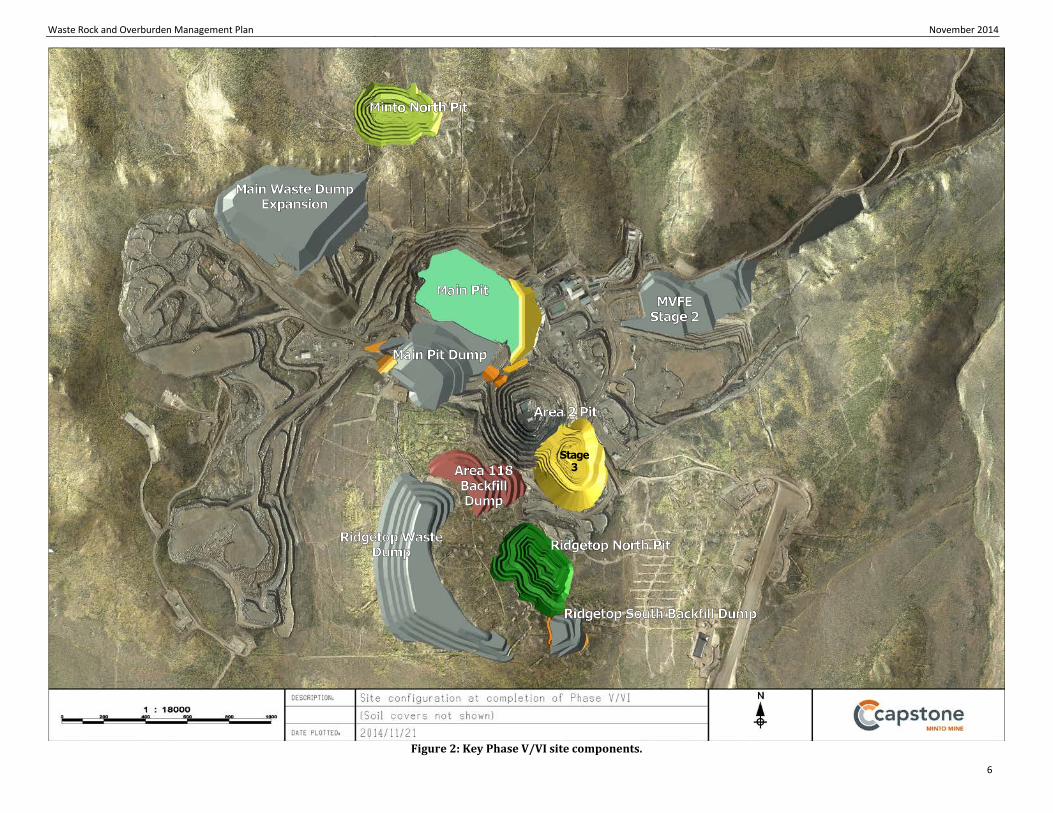
2.2 Overview of Phase V/VI Mine Plan The components of the proposed Phase V/VI mine plan that will release overburden and waste rock are shown in Figure 2; the main components are:
• Minto North Pit; • Area 2 Stage 3 Pit; • Ridgetop South Pit; • Ridgetop North Pit.
In addition, a comparatively small volume of waste rock will be released from underground mining via the Minto South Portal and the Wildfire Portal.

Waste Rock and Overburden Management Plan November 2014
5
Figure 1: Key Phase IV site components.
Waste Rock and Overburden Management Plan November 2014
6
Figure 2: Key Phase V/VI site components.

Waste Rock and Overburden Management Plan Minto Mine Phase V/VI Expansion
November 2014
7
3 Summary of Phase V/VI Materials Release
3.1 Waste Rock and Overburden The volumetric breakdown of total waste rock and overburden that will be released through Phase V/VI mining activities is shown in Table 1 and Table 2, respectively. For clarity, a bank cubic meter (BCM) is a measure of material volume (rock or overburden) in the ground, prior to mining. The process of blasting, transporting, and dumping the material increases the void space present in it; in this document, the volume of the material, when dumped, is quoted in m3. A factor of 1.30 is applied to convert BCM into loose cubic meters (m3).
Table 1: Volume of Waste Rock Released from Phase V/VI Mine Components.
Source Location Quantity (BCM) Swell Factor Waste Rock
Volume (m3)
Minto North 3,269,000 1.3 4,250,000
Area 2 Stage 3 1,465,000 1.3 1,905,000
Ridgetop South 482,000 1.3 627,000
Ridgetop North 2,628,000 1.3 3,416,000
Underground 102,000 1.3 133,000
Total Waste Rock (Phase V/VI) 10,331,000
Table 2: Volume of Overburden Released from Phase V/VI Mine Components.
Source Location Quantity (BCM) Swell Factor Overburden
Volume (m3)
Minto North 697,000 1.3 906,000
Area 2 Stage 3 2,230,000 1.3 2,899,000
Ridgetop South 135,000 1.3 176,000
Ridgetop North 702,000 1.3 913,000
Underground 0 1.3 0
Total Overburden (Phase V/VI) 4,894,000
3.2 Allowance for Waste Rock with NP:AP<3 During mining of the Main Pit, operational monitoring of waste rock for acid base accounting (ABA) parameters was carried out in accordance with water licence conditions. The results of that operational monitoring confirmed that the ABA characteristics of Main Pit waste rock were consistent with expectations based on pre-production testing (i.e., it could be classified as non-acid generating (NAG)). The water licence defined NAG material as material having a ratio of neutralization potential (NP) to acid potential (AP) greater than 3 (NP:AP>3).
During the metal leaching and acid rock drainage investigations that formed the basis of the Phase IV waste management strategy, a small proportion of drill core samples from the future Area 2 Stage 2 Pit were identified as
Waste Rock and Overburden Management Plan Minto Mine Phase V/VI Expansion
November 2014
8
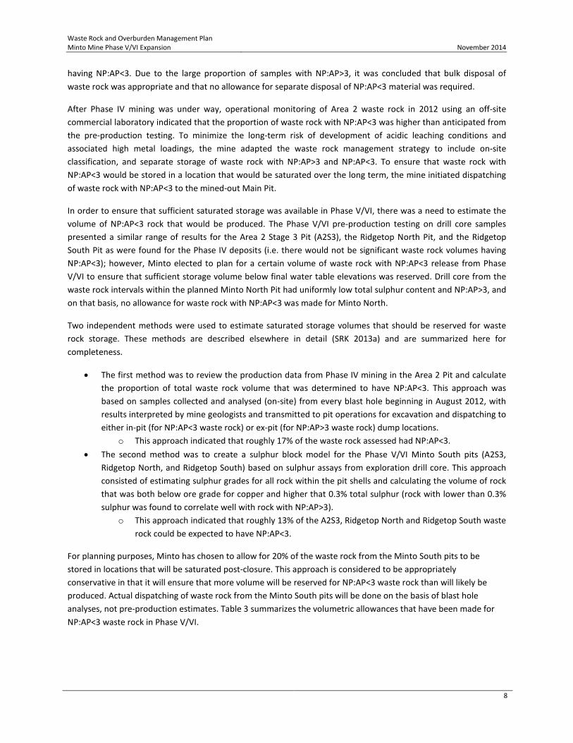
having NP:AP<3. Due to the large proportion of samples with NP:AP>3, it was concluded that bulk disposal of waste rock was appropriate and that no allowance for separate disposal of NP:AP<3 material was required.
After Phase IV mining was under way, operational monitoring of Area 2 waste rock in 2012 using an off-site commercial laboratory indicated that the proportion of waste rock with NP:AP<3 was higher than anticipated from the pre-production testing. To minimize the long-term risk of development of acidic leaching conditions and associated high metal loadings, the mine adapted the waste rock management strategy to include on-site classification, and separate storage of waste rock with NP:AP>3 and NP:AP<3. To ensure that waste rock with NP:AP<3 would be stored in a location that would be saturated over the long term, the mine initiated dispatching of waste rock with NP:AP<3 to the mined-out Main Pit.
In order to ensure that sufficient saturated storage was available in Phase V/VI, there was a need to estimate the volume of NP:AP<3 rock that would be produced. The Phase V/VI pre-production testing on drill core samples presented a similar range of results for the Area 2 Stage 3 Pit (A2S3), the Ridgetop North Pit, and the Ridgetop South Pit as were found for the Phase IV deposits (i.e. there would not be significant waste rock volumes having NP:AP<3); however, Minto elected to plan for a certain volume of waste rock with NP:AP<3 release from Phase V/VI to ensure that sufficient storage volume below final water table elevations was reserved. Drill core from the waste rock intervals within the planned Minto North Pit had uniformly low total sulphur content and NP:AP>3, and on that basis, no allowance for waste rock with NP:AP<3 was made for Minto North.
Two independent methods were used to estimate saturated storage volumes that should be reserved for waste rock storage. These methods are described elsewhere in detail (SRK 2013a) and are summarized here for completeness.
• The first method was to review the production data from Phase IV mining in the Area 2 Pit and calculate the proportion of total waste rock volume that was determined to have NP:AP<3. This approach was based on samples collected and analysed (on-site) from every blast hole beginning in August 2012, with results interpreted by mine geologists and transmitted to pit operations for excavation and dispatching to either in-pit (for NP:AP<3 waste rock) or ex-pit (for NP:AP>3 waste rock) dump locations.
o This approach indicated that roughly 17% of the waste rock assessed had NP:AP<3. • The second method was to create a sulphur block model for the Phase V/VI Minto South pits (A2S3,
Ridgetop North, and Ridgetop South) based on sulphur assays from exploration drill core. This approach consisted of estimating sulphur grades for all rock within the pit shells and calculating the volume of rock that was both below ore grade for copper and higher that 0.3% total sulphur (rock with lower than 0.3% sulphur was found to correlate well with rock with NP:AP>3).
o This approach indicated that roughly 13% of the A2S3, Ridgetop North and Ridgetop South waste rock could be expected to have NP:AP<3.
For planning purposes, Minto has chosen to allow for 20% of the waste rock from the Minto South pits to be stored in locations that will be saturated post-closure. This approach is considered to be appropriately conservative in that it will ensure that more volume will be reserved for NP:AP<3 waste rock than will likely be produced. Actual dispatching of waste rock from the Minto South pits will be done on the basis of blast hole analyses, not pre-production estimates. Table 3 summarizes the volumetric allowances that have been made for NP:AP<3 waste rock in Phase V/VI.

Waste Rock and Overburden Management Plan Minto Mine Phase V/VI Expansion
November 2014
9
Table 3: Allowance for NP:AP<3 Waste Rock Volumes in Phase V/VI Waste Management Planning.
Source Location Total Phase V/VI
Waste Rock Volume (m3)
Estimated Quantity of NP:AP<3 Waste Rock Volume
(m3)
Minto North 4,250,000 0
Area 2 Stage 3 1,905,000 381,000
Ridgetop South 627,000 125,400
Ridgetop North 3,416,000 683,200
Underground 133,000 26,600
Total Waste Rock (Phase V/VI) 10,331,000
Total NP:AP<3 (Phase V/VI) 1,216,200
A summary of saturated storage locations for NP:AP<3 material is presented in the Phase V/VI Tailings Management Plan (Minto 2014).
To address the uncertainty around the estimation of NP:AP<3 volumes, this plan provides ex-pit dump capacity for the total volume of waste rock released by Phase V/VI mining; that is, 10,331,000 m3.
4 Waste Rock Management
4.1 Introduction Planning for storage of Phase V/VI waste rock began with estimation of the quantities of waste rock expected and consideration of alternatives for storage that would contain the required volumes. Alternatives were evaluated against a suite of criteria that included foundation stability, drainage control, minimizing the need for re-handling during closure, and developing landforms that would be appropriate for closure. The outcomes of that evaluation process were summarized in a memorandum (SRK 2013b).
As noted in Section 3.2, the Phase V/VI waste rock has been classified into two categories based on ABA characteristics. These two categories are “bulk waste rock” and “NP:AP<3 waste rock”; the two categories have different storage considerations. Management of each category of waste rock is discussed separately in the following sections.
4.2 Bulk Waste Rock Waste rock from Phase V/VI operations will be stored in four primary facilities: an expansion to the Main Waste Dump, an expansion to the Mill Valley Fill Extension, and two new waste dumps developed in Phase V/VI (Main Pit Dump and Ridgetop Waste Dump).
To ensure that sufficient dump volume is available to store all bulk waste rock, the Phase V/VI dumps have been designed to contain 100% of Phase V/VI’s waste rock volume. As a portion of the Phase V/VI waste rock will be classified as NP:AP<3 and stored separately, the Phase V/VI dump designs contain more capacity than will ultimately be required. Design capacities for each Phase V/VI dump are listed in Table 4.
Waste Rock and Overburden Management Plan Minto Mine Phase V/VI Expansion
November 2014
10
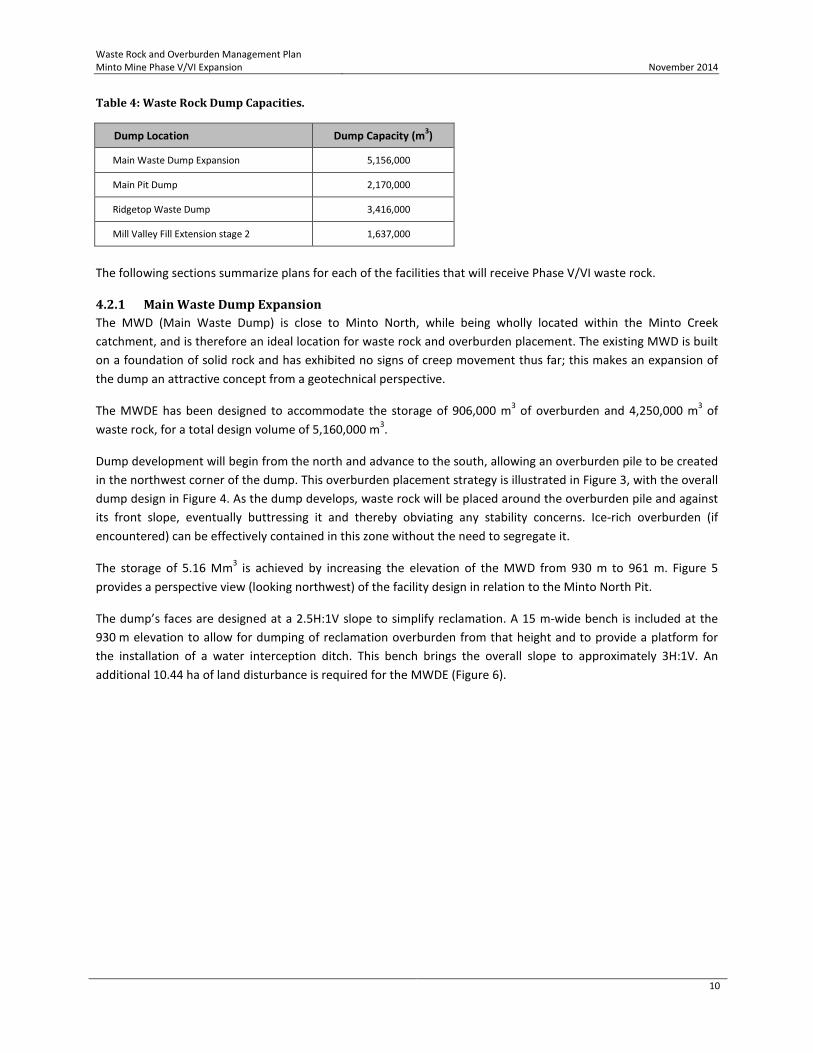
Table 4: Waste Rock Dump Capacities.
Dump Location Dump Capacity (m3)
Main Waste Dump Expansion 5,156,000
Main Pit Dump 2,170,000
Ridgetop Waste Dump 3,416,000
Mill Valley Fill Extension stage 2 1,637,000
The following sections summarize plans for each of the facilities that will receive Phase V/VI waste rock.
4.2.1 Main Waste Dump Expansion The MWD (Main Waste Dump) is close to Minto North, while being wholly located within the Minto Creek catchment, and is therefore an ideal location for waste rock and overburden placement. The existing MWD is built on a foundation of solid rock and has exhibited no signs of creep movement thus far; this makes an expansion of the dump an attractive concept from a geotechnical perspective.
The MWDE has been designed to accommodate the storage of 906,000 m3 of overburden and 4,250,000 m3 of waste rock, for a total design volume of 5,160,000 m3.
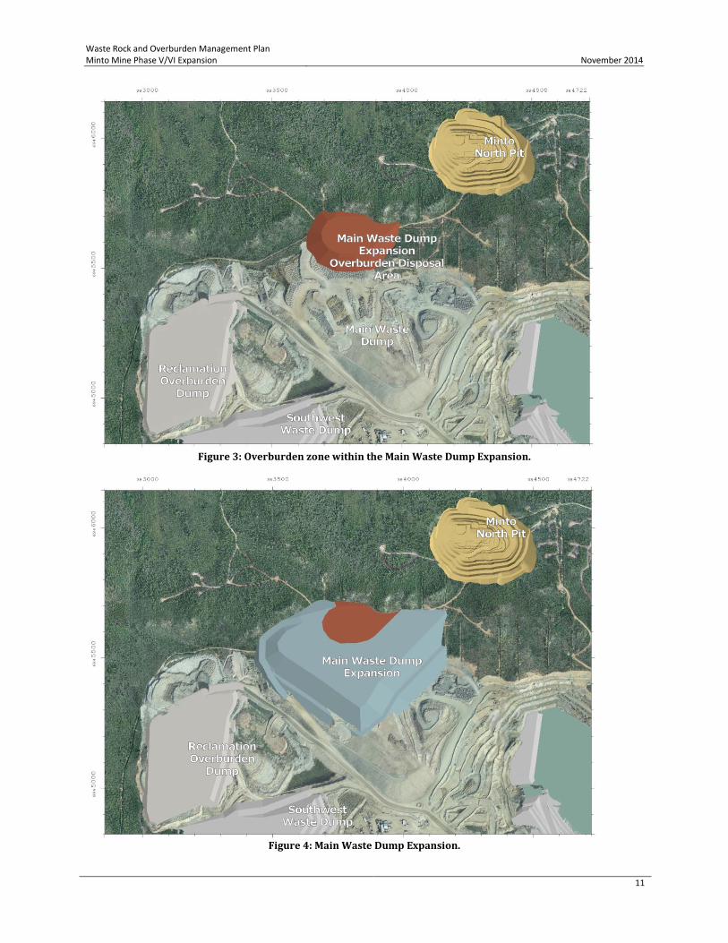
Dump development will begin from the north and advance to the south, allowing an overburden pile to be created in the northwest corner of the dump. This overburden placement strategy is illustrated in Figure 3, with the overall dump design in Figure 4. As the dump develops, waste rock will be placed around the overburden pile and against its front slope, eventually buttressing it and thereby obviating any stability concerns. Ice-rich overburden (if encountered) can be effectively contained in this zone without the need to segregate it.
The storage of 5.16 Mm3 is achieved by increasing the elevation of the MWD from 930 m to 961 m. Figure 5 provides a perspective view (looking northwest) of the facility design in relation to the Minto North Pit.
The dump’s faces are designed at a 2.5H:1V slope to simplify reclamation. A 15 m-wide bench is included at the 930 m elevation to allow for dumping of reclamation overburden from that height and to provide a platform for the installation of a water interception ditch. This bench brings the overall slope to approximately 3H:1V. An additional 10.44 ha of land disturbance is required for the MWDE (Figure 6).
Waste Rock and Overburden Management Plan Minto Mine Phase V/VI Expansion
November 2014
11
Figure 3: Overburden zone within the Main Waste Dump Expansion.
Figure 4: Main Waste Dump Expansion.

Waste Rock and Overburden Management Plan Minto Mine Phase V/VI Expansion
November 2014
12
Figure 5: Perspective view of the Main Waste Dump Expansion, the Minto North Pit, and the haul road between
them.
Figure 6: Perspective view of the additional footprint taken by the Main Waste Dump Expansion.
Minto North Pit
Main Pit (mining completed)
Oxidized Ore Stockpile
Low-Grade Ore Stockpile
N
Main Waste Dump Expansion
Additional dump footprint area: 10.44 ha
Minto North Pit
Main Pit (mining completed)
Oxidized Ore Stockpile
Low-Grade Ore Stockpile
N

Waste Rock and Overburden Management Plan Minto Mine Phase V/VI Expansion
November 2014
13
4.2.2 Main Pit Dump The basic principle of the Main Pit Dump (MPD) design is to use the footprints of the completed Main Pit (Figure 7) and the South Wall Buttress to store waste rock. The dump has a total capacity of 2.17 Mm3 and, like the Main Waste Dump Expansion, will store both waste rock and overburden.
Figure 7: Plan view of the Main Pit Dump.
The dump has 3H:1V slopes along its front face, and a wide bench is included at the 809 m elevation. The 809 m elevation will be the final height of the tailings surface in the pit after the completion of the Main Pit Tailings Management Facility. At the southeast rim of the Main Pit, a spillway will be constructed to protect the Main Dam; in closure, this spillway will convey water to the Area 2 Pit. The northwest (Main Pit) side the spillway is at the 809 m elevation, while the southeast (Area 2 Pit) side of the spillway is at the 797m elevation.
A 30 m-wide access road is designed into the front face of the dump from the 809 m elevation and will tie in to an existing road at the southwest corner of the dump; this will become the primary access linking the east and west sides of the property.
The portion of the dump below the pit’s spill elevation is designed to rest entirely upon the footprint of the Phase IV South Wall Buttress so as not to reduce the volume available for tailings in the Main Pit.
4.2.3 Ridgetop Waste Dump The Ridgetop Waste Dump (RWD) concept was developed as part of the evaluation of alternatives for Phase V/VI waste storage (SRK 2013b). The proposed RWD is located west of, and on the opposite side of the ridge from, the Ridgetop North Pit (Figure 9 and Figure 10).
The RWD design was developed to take advantage of good foundation conditions (i.e. weathered bedrock and residual soils over a large area of the proposed dump footprint) and to avoid areas underlain by ice-rich

Waste Rock and Overburden Management Plan Minto Mine Phase V/VI Expansion
November 2014
14
overburden. A secondary design consideration was to locate the footprint of the RWD primarily on the west side of the north-south drainage divide located west of (and at higher elevation from) the Ridgetop pits; this would ensure that most of the RWD drainage would report to the western catchment (the W15 catchment) that already contains the SWD and the MWD, and would minimize the waste dump seepage reporting eastward to the eastern catchment (the W35 catchment).
Figure 8: Footprint of the Ridgetop Waste Dump in relation to catchment area divisions.
The RWD will have a capacity of 3.4 Mm3. The disturbance area of the reclaimed RWD is estimated to be 28.8 ha, of which 25.4 ha is located within the W15 catchment and 3.4 ha is within the W35 catchment; the dump’s footprint is shown in Figure 8.
W15 Catchment
W35 Catchment
N

Waste Rock and Overburden Management Plan Minto Mine Phase V/VI Expansion
November 2014
15
Figure 9: Plan view of the Ridgetop Waste Dump.
Figure 10: Perspective view of the Ridgetop Waste Dump.
4.2.4 Mill Valley Fill Extension Stage 2 The existing Mill Valley Fill Extension was designed as a buttress to arrest the movement of the slope underlying the DSTSF (dry stack tailings storage facility). Monitoring of survey hubs at various locations around the DSTSF has shown that rates of movement have decreased significantly since the start of MVFE construction.
An extensive program of geotechnical investigation and analysis, aimed at better defining the mechanism causing the DSTSF slope movement and evaluating what additional mitigations are required to fully halt movement and stabilize the slope, has been completed. A further expansion of the Mill Valley Fill Extension, adding more rockfill to the existing buttress both vertically as well as to the east along the axis of the Minto Creek valley, has been shown to improve the long-term slope stability of the DSTSF.
Waste Rock and Overburden Management Plan Minto Mine Phase V/VI Expansion
November 2014
16
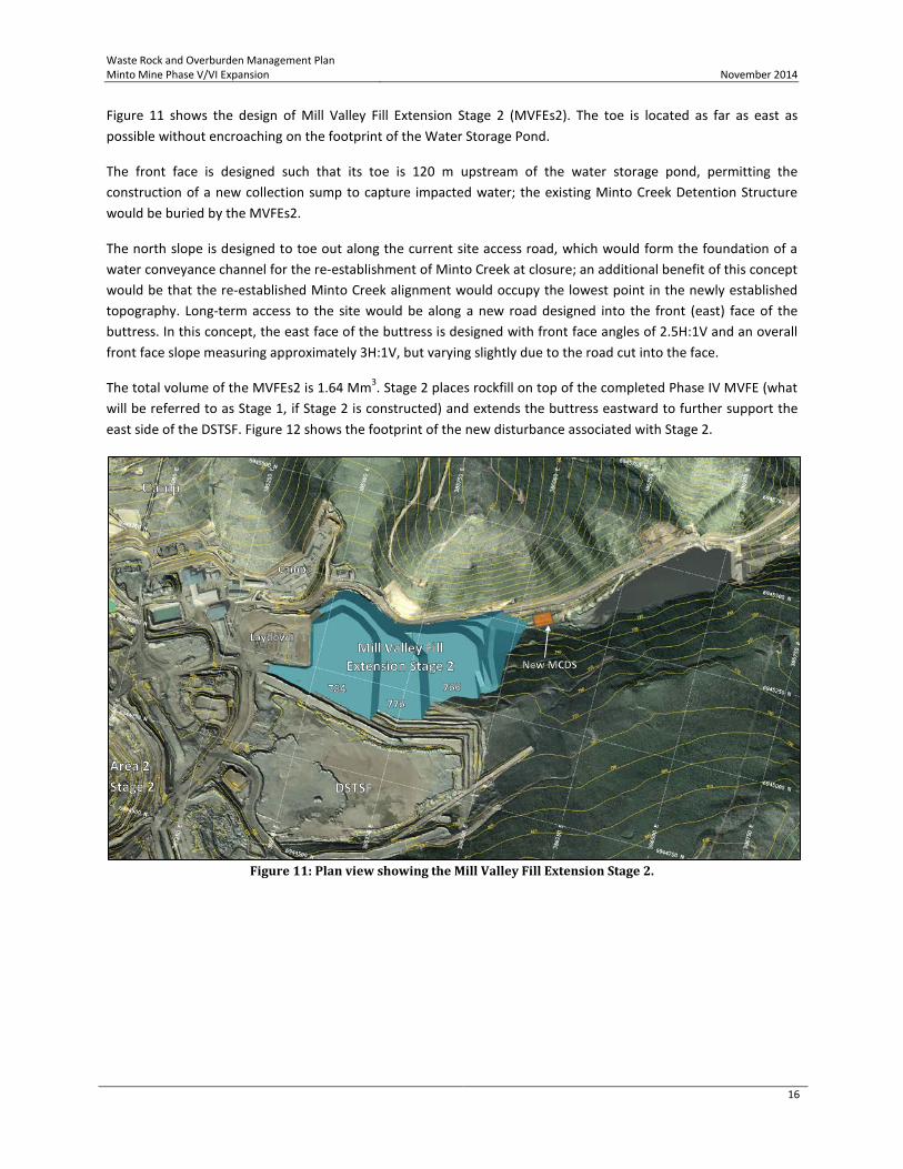
Figure 11 shows the design of Mill Valley Fill Extension Stage 2 (MVFEs2). The toe is located as far as east as possible without encroaching on the footprint of the Water Storage Pond.
The front face is designed such that its toe is 120 m upstream of the water storage pond, permitting the construction of a new collection sump to capture impacted water; the existing Minto Creek Detention Structure would be buried by the MVFEs2.
The north slope is designed to toe out along the current site access road, which would form the foundation of a water conveyance channel for the re-establishment of Minto Creek at closure; an additional benefit of this concept would be that the re-established Minto Creek alignment would occupy the lowest point in the newly established topography. Long-term access to the site would be along a new road designed into the front (east) face of the buttress. In this concept, the east face of the buttress is designed with front face angles of 2.5H:1V and an overall front face slope measuring approximately 3H:1V, but varying slightly due to the road cut into the face.
The total volume of the MVFEs2 is 1.64 Mm3. Stage 2 places rockfill on top of the completed Phase IV MVFE (what will be referred to as Stage 1, if Stage 2 is constructed) and extends the buttress eastward to further support the east side of the DSTSF. Figure 12 shows the footprint of the new disturbance associated with Stage 2.
Figure 11: Plan view showing the Mill Valley Fill Extension Stage 2.

Waste Rock and Overburden Management Plan Minto Mine Phase V/VI Expansion
November 2014
17
Figure 12: Land disturbance associated with the Mill Valley Fill Extension Stage 2.
4.3 NP:AP<3 Waste Rock
4.3.1 Storage As noted in Section 3.2, the Phase V/VI Waste Management Plan has been developed with an allowance for 1.2 Mm3 of waste rock with NP:AP<3 to be stored in locations that will be saturated over the long term. For planning purposes, 20% of the waste rock from A2S3, Ridgetop North and Ridgetop South pits is assumed to have NP:AP<3, and that this material should be stored such that it is saturated post-closure. It is not necessary to saturate NP:AP<3 waste rock during the operational period—there is sufficient neutralization potential in the NP:AP<3 waste that any acid generated at the mineral grain scale will be neutralized by contact with nearby neutralizing minerals and porewater that is in contact with those neutralizing minerals (SRK 2013a).
Minto plans to dispose of all rock with NP:AP<3 in the both the Main Pit and the Area 2 Pit below the final water table elevation in the respective pits. Rock will be both free-dumped over dump crests, and end-dumped in lifts and spread by dozer. Although deposition of tailings and NP:AP<3 waste rock will occur simultaneously, mixing of rock and tailings will be minimal and limited to coincidental mixing only. To the extent that tailings occupy waste rock void space, storage efficiency will increase; for planning purposes, it is assumed that no mixing of waste rock and tailings occurs and that discrete storage volumes are required for the scheduled release of both products. The tailings management plan has been developed to allow for disposal of both tailings and NP:AP<3 waste rock as described here (Minto 2013). Minto may consider using NP:AP<3 rock as underground mine backfill at some point, although planning is not sufficiently advanced at this stage to define whether this is feasible. If underground backfill of waste rock is undertaken, all NP:AP<3 waste rock backfill will placed in workings that are below the respective portal elevation and are expected to be saturated in the long term. This underground backfill strategy is consistent with the concept of disposing of NP:AP<3 waste rock under saturated conditions.
Waste Rock and Overburden Management Plan Minto Mine Phase V/VI Expansion
November 2014
18
4.3.2 Classification and Segregation Minto intends to continue the classification and segregation practices developed and implemented in 2012 as part of pit operations in the Phase IV Area 2 Stage 1/ 2 Pit. These practices can be summarized as follows:
• Classification 1. Samples of cuttings from each blast hole are collected for grade control purposes. One sample is
collected per hole. 2. Cuttings samples are split into aliquots for grade control (copper analysis) and for determination
of total sulphur (S(T)) and total carbon (C(T)) content. 3. S(T) and C(T) are measured for each sample using an Eltra CS-800 induction furnace with infrared
detectors. 4. Test results are imported into the mine’s grade control software for processing by the mine
geologists. 5. S(T) and C(T) values are converted into equivalent acid potential (AP-S(T)) and neutralization
potential (NP-C(T)) values, and NP-C(T):AP-S(T) ratios are calculated for each sample. 6. NP-C(T):AP-S(T) values are plotted for each drill hole in a given blast pattern, and mine geologists
use the mine’s grade control software to define polygons outlining contiguous zones of waste rock types: either bulk waste or waste with an NP-C(T):AP-S(T) ratio less than 3.0.
7. Ore grade polygons are drawn for material above the mine’s operational cutoff grade, with the result being that all material in a blast is classified as ore, bulk waste, or NP:AP<3 waste rock.
8. A map of the final ore and waste classifications is provided to the pit operations team to guide the dispatching of all rock released from the pit.
• Segregation 1. The pit operations team uses the blast classification maps to stake out the boundaries of each
ore and waste class. Each class is represented by stakes in different colours. The maps are also used to communicate the shift’s plans with equipment operators and supervisors at the beginning of each shift.
2. Haul trucks are loaded by a loader or excavator, the operator of which is responsible for knowing the material class being excavated and for communicating the class of each load to the haul truck operator.
3. The haul truck driver then delivers the load to the crusher or to the appropriate stockpile (if ore) or waste storage facility (if waste).
4.4 Construction Rock To limit potential metal leaching, waste rock that is used for general construction purposes (e.g. road building, armouring of ditches, road crush) will be restricted to rock with the following properties:
1. NP/AP > 3.0 2. Total Sulphur < 0.30% 3. Total Copper < 0.10%
All of the above characteristics will be defined using on-site testing to allow for the short cycle times that are necessary for efficient dispatching of rock produced as part of mining operations.

Waste Rock and Overburden Management Plan Minto Mine Phase V/VI Expansion
November 2014
19
5 Overburden Management Overburden produced during mining of Phase V/VI open pits will be used for progressive reclamation of completed mine facilities, bulk-disposed in waste dumps with waste rock, or stored in overburden-specific dumps and reclamation stockpiles. The following sections summarize how the Phase V/VI overburden will be managed.
5.1 Progressive Reclamation Minto intends to carry out reclamation work on certain completed facilities during Phase V/VI mining. As indicated in Table 2, the largest quantity of overburden will be released during mining of the A2S3 Pit. The A2S3 overburden will be dispatched to the following locations for use as reclamation cover:
• Main Waste Dump Expansion; • Southwest Waste Dump (low-, mid-, and high-grade waste areas); • Dry Stack Tailings Storage Facility.
The overburden volumes to be dispatched to these locations are listed in Table 5. Direct placement of overburden in other areasthat require covers for closure (for example, the Mill Valley Fill Extension) may also be carried out .
Table 5: Destinations for Overburden Released from Phase V/VI Mine Components.
Location Volume (m3)
Southwest Waste Dump - low-grade waste area cover 365,000
Southwest Waste Dump - mid- and high-grade waste area cover 306,000
Main Waste Dump Expansion cover 400,000
Dry Stack Tailings Storage Facility 490,000
Main Waste Dump Expansion 906,000
Area 118 Backfill Dump 1,338,000
Main Pit Dump 349,000
Ridgetop South Backfill Dump 740,000
Total 4,894,000
5.2 Area 118 Backfill Dump A new overburden dump will be developed as part of Phase V/VI in the general area of the Phase IV Area 118 Pit, first backfilling it and then constructing a dump on and around the footprint of the pit. All material dispatched to this dump will be overburden. Below the low point in the pit rim (approximate elevation 862 m), backfill will be a combination of thaw-stable and ice-rich overburden. Above this elevation, the pit backfill will consist of thaw-stable overburden only.
The footprint of the Area 118 Backfill Dump is shown in Figure 13 and, excluding the portion within the mined-out Area 118 Pit, measures 3.6 ha.
The Area 118 Backfill Dump shown is shown in Figure 14. It is designed with overall side slopes of 3H:1V, face angles of 3H:2V, and has a capacity of 1.3 Mm3 (Table 5).

Waste Rock and Overburden Management Plan Minto Mine Phase V/VI Expansion
November 2014
20
Figure 13: Footprint of the Area 118 Backfill Dump.
Figure 14: Area 118 Backfill Dump.
During Phase V/VI reclamation activities, the Area 118 Backfill Dump will be used as a source of cover material for the Ridgetop area facilities (ACG 2014).
5.3 Main Waste Dump Expansion The Main Waste Dump will receive approximately 906,000 m3 of overburden, which will be placed at the northwest corner of the dump, buttressed by a larger volume of waste rock, as described in Section 4.2.1.

Waste Rock and Overburden Management Plan Minto Mine Phase V/VI Expansion
November 2014
21
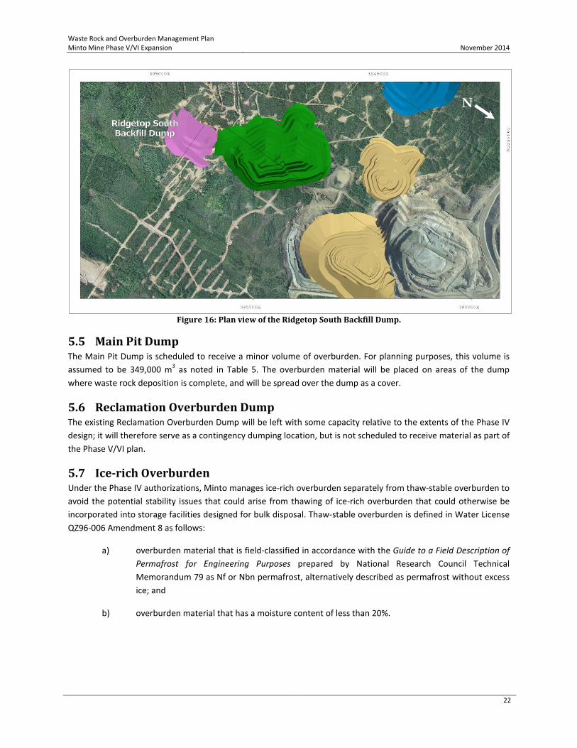
5.4 Ridgetop South Backfill Dump Ridgetop South Backfill Dump is designed to contain 740,000 m3 of overburden. The dump backfills and builds upon the footprint of the Ridgetop South Pit (Figure 15 and Figure 16).
The Ridgetop South Backfill Dump will be mounded up above the pre-mining surface topography such that final side slopes will form 3H:1V (or shallower) surfaces. The purpose of mounding backfill above the original topography is fourfold:
• to eliminate the Ridgetop South Pit as a long term surface feature at the site;
• to avoid surface depressions that could result from settling of backfill;
• to provide positive drainage and maximize surface runoff during the post-closure period; and
• to maximize volume of waste stored within the footprint of the Ridgetop South Pit.
Figure 15: Perspective view of the Ridgetop South Backfill Dump.
Waste Rock and Overburden Management Plan Minto Mine Phase V/VI Expansion
November 2014
22
Figure 16: Plan view of the Ridgetop South Backfill Dump.
5.5 Main Pit Dump The Main Pit Dump is scheduled to receive a minor volume of overburden. For planning purposes, this volume is assumed to be 349,000 m3 as noted in Table 5. The overburden material will be placed on areas of the dump where waste rock deposition is complete, and will be spread over the dump as a cover.
5.6 Reclamation Overburden Dump The existing Reclamation Overburden Dump will be left with some capacity relative to the extents of the Phase IV design; it will therefore serve as a contingency dumping location, but is not scheduled to receive material as part of the Phase V/VI plan.
5.7 Ice-rich Overburden Under the Phase IV authorizations, Minto manages ice-rich overburden separately from thaw-stable overburden to avoid the potential stability issues that could arise from thawing of ice-rich overburden that could otherwise be incorporated into storage facilities designed for bulk disposal. Thaw-stable overburden is defined in Water License QZ96-006 Amendment 8 as follows:
a) overburden material that is field-classified in accordance with the Guide to a Field Description of Permafrost for Engineering Purposes prepared by National Research Council Technical Memorandum 79 as Nf or Nbn permafrost, alternatively described as permafrost without excess ice; and
b) overburden material that has a moisture content of less than 20%.
N

Waste Rock and Overburden Management Plan Minto Mine Phase V/VI Expansion
November 2014
23
Overburden that does not meet these thaw-stable criteria will be designated ‘ice-rich overburden’ and will be handled separately as follows:
• Ice-rich overburden from Minto North will be co-disposed with thaw-stable overburden as described in Section 4.2.1; briefly, all overburden will be placed in the northwest corner of the dump, where it will be buttressed by a large quantity of waste rock.
• The portions of the Area 118 and the Ridgetop South backfill dumps that are below the elevations of the lowest point along the pit rim will be able to receive ice-rich overburden co-disposed with thaw-stable overburden.
• Ice-rich overburden will be placed together with thaw-stable overburden as part of the progressive reclamation work done on Phase IV dumps. With anticipated placed overburden thicknesses of up to a few metres thick, and with only a small proportion of overburden expected to be classified as ice-rich, any ice entrained in the cover layer is expected to thaw within one year of placement and any excess water that results will drain or evaporate.
Prepared by: Original Signed and Stamped By _______________________________ Daniel Avar, PEng Long Range Planning Engineer Reviewed by: Original Signed and Stamped By _______________________________ Pooya Mohseni, MBA, MASc., PEng Chief Engineer
Waste Rock and Overburden Management Plan Minto Mine Phase V/VI Expansion
November 2014
24
6 References Access Consulting Group. 2014. Minto Mine Phase V/VI Expansion, Preliminary Reclamation and Closure Plan. Minto Explorations Ltd. 2013. Minto Mine Phase V/VI Expansion, Tailings Management Plan v.2013-01. SRK Consulting. 2013a. Minto Mine Phase V/VI Expansion, Metal Leaching and Acid Rock Drainage Assessment and
Inputs to Water Quality Predictions. Report prepared for Capstone Mining Corporation. SRK Consulting. 2013b. Minto Mine – Phase V/VI Waste Storage Alternatives Assessment. Memorandum prepared
for Capstone Mining Corporation. SRK Consulting. 2013c. Phase V/VI Main Waste Dump Expansion - Physical Stability Assessment. Report prepared
for Capstone Mining Corporation. SRK Consulting. 2013d. Phase V/VI Ridgetop South & Area 118 Backfill Dumps Physical Stability Assessment. Report
prepared for Capstone Mining Corporation. SRK Consulting. 2013e. Phase V/VI Main Pit Dump Physical Stability Assessment. Report prepared for Capstone
Mining Corporation. SRK Consulting. 2013f. Phase V/VI Ridgetop Waste Dump Physical Stability Assessment. Report prepared for
Capstone Mining Corporation. SRK Consulting. 2014. Mill Valley Fill Extension Stage 2 Preliminary Design Report. Report prepared for Capstone
Mining Corporation. Norwest Corporation. 2014. Minto Main Pit Dump Design Independent Geotechnical Review