waste and overburden management plan, phase iv development ... · pdf fileminto explorations...
TRANSCRIPT

E
MINTO EXPLORATIONS LTD.
WASTE ROCK AND OVERBURDEN MANAGEMENT PLANPHASE IV DEVELOPMENT
MINTO MINE, YT
REPORT
SEPTEMBER 9, 2011ISSUED FOR USE
BA FILE: W14101068.015
EBA, A Tetra Tech CompanyCalcite Business Centre, Unit 6, 151 Industrial Road
Whitehorse, YT Y1A 2V3 CANADAp. 867.668.3068 f. 867.668.4349
LIMITATIONS OF REPORT
This report and its contents are intended for the sole use of Minto Explorations Ltd. and their agents. EBA, A Tetra Tech
Company, does not accept any responsibility for the accuracy of any of the data, the analysis, or the recommendations
contained or referenced in the report when the report is used or relied upon by any Party other than Minto Explorations Ltd., or
for any Project other than the proposed development at the subject site. Any such unauthorized use of this report is at the
sole risk of the user. Use of this report is subject to the terms and conditions stated in EBA’s Services Agreement. EBA’s
General Conditions are provided in Appendix A of this report.

WASTE MANAGEMENT PLAN – PHASE IV DEVELOPMENT
EBA FILE: W14101068.015 | SEPTEMBER 9, 2011 | ISSUED FOR USE
i
Waste and Overburden Management Plan, Phase IV Development Report - IFU.docx
TABLE OF CONTENTS
1.0 INTRODUCTION................................................................................................................................. 1
2.0 PROPERTY DESCRIPTION AND BACKGROUND INFORMATION........................................ 1
2.1 General Location and Access .......................................................................................................... 1
2.2 Topography and Vegetation............................................................................................................. 1
2.3 Permafrost....................................................................................................................................... 2
2.4 Regional Geology ............................................................................................................................ 2
2.5 Climate............................................................................................................................................ 3
2.5.1 Temperature ....................................................................................................................... 3
2.5.2 Wind ................................................................................................................................... 3
2.5.3 Precipitation ........................................................................................................................ 4
2.5.4 Solar Radiation.................................................................................................................... 4
2.6 Status.............................................................................................................................................. 4
2.7 History ............................................................................................................................................. 4
3.0 OBJECTIVES OF THE WASTE ROCK AND OVERBURDEN MANAGEMENT PLAN .......... 5
4.0 WASTE CHARATERISTICS AND SEGREGATION...................................................................... 5
4.1 Types of Waste................................................................................................................................ 5
4.2 Waste Characteristics ...................................................................................................................... 5
4.2.1 Overburden......................................................................................................................... 5
4.2.2 Waste Rock......................................................................................................................... 6
4.3 Waste Segregation Protocol............................................................................................................. 6
5.0 WASTE RELEASE AND DISPOSAL SCHEDULE.......................................................................... 8
5.1 Waste Volumes ............................................................................................................................... 8
5.2 Waste Disposal Schedule ................................................................................................................ 9
6.0 WASTE DUMP DESIGN ...................................................................................................................10
6.1 General Design Criteria.................................................................................................................. 10
6.2 Closure Considerations.................................................................................................................. 12
6.3 Surface Drainage Considerations................................................................................................... 12
6.4 Mill Valley Fill Expansion................................................................................................................ 12
6.4.1 Design Considerations ...................................................................................................... 12
6.4.2 Design Details................................................................................................................... 13
6.4.3 Closure Plan ..................................................................................................................... 14
6.5 Southwest Waste Dump Expansion ............................................................................................... 15
6.5.1 General Description of Waste Disposal.............................................................................. 15
6.5.2 Design Considerations ...................................................................................................... 16
6.5.3 Design Details................................................................................................................... 16
6.5.4 Closure Plan ..................................................................................................................... 17
6.6 Area 1 South Wall Buttress ............................................................................................................ 17

WASTE MANAGEMENT PLAN – PHASE IV DEVELOPMENT
EBA FILE: W14101068.015 | SEPTEMBER 9, 2011 | ISSUED FOR USE
ii
Waste and Overburden Management Plan, Phase IV Development Report - IFU.docx
6.6.1 Design .............................................................................................................................. 17
6.6.2 Buttress Construction ........................................................................................................ 17
6.6.3 Closure Plan ..................................................................................................................... 18
6.7 Reclamation Material Stockpiles .................................................................................................... 18
6.7.1 Design Considerations ...................................................................................................... 18
6.7.2 Design Details................................................................................................................... 18
6.7.3 Closure Plan ..................................................................................................................... 19
7.0 GENERAL RECOMMENDATIONS FOR CONSTRUCTION.....................................................19
7.1 Site Preparation During Waste Disposal......................................................................................... 19
7.2 Reclamation of Overburden Waste................................................................................................. 19
8.0 MONITORING PROGRAM...............................................................................................................19
9.0 CLOSURE.............................................................................................................................................20
REFERENCES ................................................................................................................................................21
FIGURES
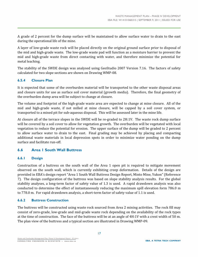
Figure WMP-01 Overall Site Plan - Waste Storage Components
Figure WMP-02 Overburden Release from Phase IV Mine Expansion
Figure WMP-03 Waste Rock Release from Phase IV Mine Expansion
Figure WMP-04 Waste Flow Charts
Figure WMP-05 Site Plan - Mill Valley Fill Expansion
Figure WMP-06 Sections - Mill Valley Fill Expansion
Figure WMP-07 Site Plan - Southwest Waste Dump Expansion
Figure WMP-08 Section - Southwest Waste Dump Expansion
Figure WMP-09 Area 1 Open Pit South Wall Buttress Plan and Profile
Figure WMP-10 Site Plan – Mill Valley and Airport Reclamation Stockpiles
Figure WMP-11 Sections – Mill Valley and Airport Reclamation Material Stockpiles
APPENDICES
Appendix A General Conditions

WASTE MANAGEMENT PLAN – PHASE IV DEVELOPMENT
EBA FILE: W14101068.015 | SEPTEMBER 9, 2011 | ISSUED FOR USE
1
Waste and Overburden Management Plan, Phase IV Development Report - IFU.docx
1.0 INTRODUCTION
Minto Explorations Ltd. (Minto) is proposing the Phase IV Mine Expansion at the Minto Mine site, located
north of Carmacks, YT. According to Minto’s Project Proposal (Reference 1), the Phase IV expansion
includes development of the Area 2 and Area 118 open pits and underground workings, as well as,
associated waste management and other ancillary activities. Minto requested that EBA, a Tetra Tech
Company (EBA) prepare a waste rock and overburden management plan for the expansion of existing
waste rock and overburden disposal facilities as part of the Phase IV development. The following areas
shown on the Drawing WMP-01 are designated for waste disposal as part of this Phase IV Waste Rock and
Overburden Management Plan (WROMP):
The Mill Valley Fill Expansion (MVFE);
The Southwest Waste Dump Expansion (SWDE);
The Area 1 South Wall Buttress; and
Reclamation Material Stockpiles.
This report summarizes the planned waste rock and overburden management activities and associated
components that will be required for Phase IV development. As referenced in this report, “waste” consists
of overburden and waste rock removed during mining operations. Tailings waste management is discussed
in a separate document: “Phase IV Tailings Management Plan Minto Mine, YT”. This document also does
not address open pit development.
2.0 PROPERTY DESCRIPTION AND BACKGROUND INFORMATION
2.1 General Location and Access
The Minto Mine is located in the Whitehorse Mining District in the central Yukon Territory. The property is
located approximately 240 km northwest of Whitehorse, the Yukon capital. The project is centered on NAD
83, UTM Zone 8, coordinates 6945147N, 385443E. The mine is in commercial production, and has a Type B
Water License: MS04-227.
The Minto Mine is accessed either by land via the North Klondike Highway and Minto Access Road, or by
air. Access by land requires crossing the Yukon River, which is completed by barge in the summer and ice
road in the winter. There are periods of time in the spring and fall that land access is not possible, as
neither the ice road nor the barge is available for use.
2.2 Topography and Vegetation
The Minto Mine property lies in the Dawson Range, which is part of the Klondike Plateau, an uplifted
surface that has been dissected by erosion. Topography in the area consists of rounded rolling hills and
ridges. The highest elevation on the property is 975 m (3,200 ft.) above sea level, compared to elevations
of 460 m (1,500 ft.) along the Yukon River. The Minto Mine property consists of rolling hills, and slopes are

WASTE MANAGEMENT PLAN – PHASE IV DEVELOPMENT
EBA FILE: W14101068.015 | SEPTEMBER 9, 2011 | ISSUED FOR USE
2
Waste and Overburden Management Plan, Phase IV Development Report - IFU.docx
relatively gentle. The hills and ridges often have spines of bedrock outcrops; elsewhere bedrock exposures
are limited in the area.
Overburden is typically colluvium primarily made up of sand derived from decomposition of the largely
granitic bedrock in the area. The overburden is generally thin but pervasive over the site. In south-facing
locations, this material provides a well-drained, sound foundation for buildings and roads. Vegetation in
the area is sub-Arctic boreal forest made up of largely spruce evergreen trees and poplar deciduous trees.
The trees prefer well-drained south-facing slopes and may be sparse on the north-facing slopes where
moss and alder or ‘buck brush’ prevails. The area has been impacted by several wild fires, the latest of
which was in 1995. Many of the burnt trees have blown down and natural regrowth of pine and alder is
occurring over much of the property.
2.3 Permafrost
The mine is in a location of widespread discontinuous permafrost. In general, south facing slopes at lower
elevations are unfrozen and north facing slopes contain permafrost. The Minto Creek valley bottom
contains permafrost on both the north and south sides, particularly in areas with insulating moss cover.
Measured ground temperatures are generally warmer than -2 degrees C, with ground ice contents ranging
from non-visible-bonded (Nbn) to visible stratified ice (Vs) up to 20% by volume. The thick lacustrine
clay/silt may locally contain Vs up to 60% by volume, and is frozen to depths in excess of 50 m below
ground surface. Massive ice up to 4 m thick has been encountered in some boreholes.
2.4 Regional Geology
The Minto Project is found in the eastern margin of the Yukon-Tanana Composite Terrain, which is
comprised of several metamorphic assemblages and batholiths. It is broadly contemporaneous with the
Omineca Belt in nearby British Columbia.
The Minto Property and surrounding area are underlain by plutonic rocks of the Granite Mountain
Batholith (Early Mesozoic Age). They vary in composition from quartz diorite and granodiorite to quartz
monzonite. The batholith is unconformably overlain by clastic sedimentary rocks of the Tantalus
Formation and andesitic to basaltic volcanic rocks of the Carmacks Group, both are assigned a Late
Cretaceous age. Immediately flanking the Granite Mountain Batholith, to the east, is a package of undated
mafic volcanic rocks, outcropping on the shores of the Yukon River. The structural relationship between
the batholith and the undated mafic volcanics is poorly understood because the contact zone is not
exposed.
Lithologically the Property is underlain by predominantly igneous rocks of granodiorite composition. In
the few available outcrops and drill core, two basic units are distinguished, an equigranular phase and a
potassic feldspar megacrystic phase. The equigranular phase is relatively leucocratic, grey to whitish in
colour and uniform in texture. The potassic-feldspar megacrystic phase can be slightly darker, may contain
more biotite and hornblende, and may be light pink in color. In surface exposures, the latter exhibits a very
weak alignment of the feldspar megacrysts, defining an interpreted magmatic foliation.
Other rock types, albeit volumetrically insignificant include dykes of simple quartz-feldspar pegmatite,
aplite and an aphanitic textured intermediate composition rock. Bodies of all of these units are relatively

WASTE MANAGEMENT PLAN – PHASE IV DEVELOPMENT
EBA FILE: W14101068.015 | SEPTEMBER 9, 2011 | ISSUED FOR USE
3
Waste and Overburden Management Plan, Phase IV Development Report - IFU.docx
thin and rarely exceed one-metre core intersections. These dykes are relatively late, generally postdating
the peak ductile deformation event; however, some pegmatite and aplite bodies observed in a rock cut
located north of the mill complex are openly folded. Conglomerate and volcanic flows have been logged in
drill core by past operators but have not been confirmed by the authors as the drill core from previous
campaigns was largely destroyed in forest fires and no new drilling has intersected such rocks.
2.5 Climate
The climate in the Minto region is ‘subarctic continental’ characterized by long, cold winters and short cool
summers. The area experiences moderate precipitation in the form of rain and snow and a large range of
temperatures on a yearly basis with a mean annual temperature below 0°C.
2.5.1 Temperature
The mean annual temperature in this region is -1.9°C. The summer period, between late-May and early-
September, is characterized by temperatures that range from 10°C to 20°C. The winter period, between
October and March, is characterized by a much larger day-to-day variation in air temperatures, ranging
from 0°C to -40°C, although typical winter temperatures range from -10°C to -30°C. Diurnal variation in air
temperatures tends to be less during the winter period than during the summer. The transitions between
Winter and Summer are characterized by a quick rise or fall in air temperatures during March/late May
and mid-September/early-October, respectively.
Based on the data record, air temperatures would be expected to remain above zero throughout the day
between June and September, while between October and March; air temperatures would typically remain
below zero. The maximum air temperature ever recorded was 30.3°C on July 29, 2009. The minimum air
temperature ever recorded was -43.2°C on November 27, 2006 and again on January 8, 2009. Air
temperatures in excess of 5°C have been observed in every winter month. Sub-zero temperatures have
been recorded every month except July and August.
2.5.2 Wind
Severe rime ice build-up on the anemometer cups has resulted in extended periods of recorded zero or
diminished wind speeds during the winter (EBA, 2010). In order to remove any uncertainty in the data, all
wind speeds recorded below 0°C were omitted from analysis. As a result, the description of winds at the
property excludes the majority of observations occurring November through March and does not provide a
complete assessment of winds at the property.
Based only on recorded winds at temperatures above 0°C, winds predominantly blow from two directions:
the south (including SSW, S, and SSE), 23.5% of the time and the northwest (including NNW, NW, and
WNW) 17.8% of the time. Wind speeds are typically low, exceeding 6 m/s only 5% of the time. The mean
annual wind speed is 3.4 m/s. Winds are slightly weaker during the summer months however, because the
majority of winter winds have either been omitted due to inaccurate measurement or were not recorded
due to rime ice, the degree of difference between summer and winter winds has not yet been fully
observed.

WASTE MANAGEMENT PLAN – PHASE IV DEVELOPMENT
EBA FILE: W14101068.015 | SEPTEMBER 9, 2011 | ISSUED FOR USE
4
Waste and Overburden Management Plan, Phase IV Development Report - IFU.docx
The annual mean wind gust speed is 7.1 m/s. The highest recorded instantaneous gust was 23.8 m/s
although higher wind gusts have likely occurred during the winter and have not been recorded.
2.5.3 Precipitation
Total annual precipitation recorded at Pelly Ranch and Carmacks between 1955 and 2006 were observed
to determine the regional trend over central Yukon during the last half of the 20th century. The results
showed that the mean annual precipitation is 275 mm. The results also indicated a general increase of 1.1
mm/year and 1.4 mm/year in annual precipitation over the 51-year period at Pelly Ranch and Carmacks,
respectively. This equates to more than a 20% increase. The effects of climate change on precipitation
patterns are quite complex as they vary locally. The proximity of the Environment Canada stations to the
mine site would allow for reasonable confidence in assuming that the observed trends for Pelly Ranch and
Carmacks are also applicable to the Minto site, excluding regional variability of precipitation events due to
orographic effects or valley orientations.
2.5.4 Solar Radiation
As would be expected at a latitude near 62 °N, a strong seasonal pattern is evident, with maximum solar
radiation being received near the summer solstice in late June (daily maximums on the order of
750 W/m2), and values just slightly above zero around the winter solstice when the site experiences only
about 3 hours of direct sunlight. Large fluctuations from the general trend during the summer are due to
cloud cover.
2.6 Status
Minto has been in production since June 2007. Development of the Area 1 open pit commenced in
April 2006, and currently operates on an ongoing basis with either ore being stockpiled for processing
and/or waste materials being disposed of at one of the waste dumps. There are currently four waste
dumps permitted at the Minto Mine: the Main Waste Dump (MWD), the Reclamation Overburden Dump
(ROD), the Ice-Rich Overburden Dump (IROD), and the Southwest Waste Dump (SWD). The current waste
dumps are used to store the following materials:
MWD — used to store both non ice-rich overburden and waste rock materials;
ROD — used to store non-ice rich overburden for possible use in future reclamation;
IROD — used to store ice-rich overburden; and
SWD — used to store non-ice rich overburden and waste rock materials.
To facilitate future operations and reclamation, Minto is proposing the design and construction of waste
management plan components to store mined overburden and waste rock.
2.7 History
The following historical information was gathered from the Capstone Mining Corp. website1.
1 http://capstonemining.com/s/Minto.asp?ReportID=343895

WASTE MANAGEMENT PLAN – PHASE IV DEVELOPMENT
EBA FILE: W14101068.015 | SEPTEMBER 9, 2011 | ISSUED FOR USE
5
Waste and Overburden Management Plan, Phase IV Development Report - IFU.docx
The Minto project has a history of exploration and development dating back to the early 1970's. In the
mid-1990's, a feasibility study was completed by prior owners, permits obtained and construction of an
open pit mine commenced. During that period, the mill foundations were poured, the ball and SAG mills
were purchased and moved to site, a permanent camp constructed and the site connected to a permitted
Yukon River crossing via a 29 km production standard access road. Construction was suspended in 1997
after expenditures of approximately $10 million due to depressed copper prices.
Capstone's predecessor, Sherwood Copper, acquired the Minto Project in June 2005 and, in just two years
from acquisition, re-drilled the deposit to modern reserve standards, completed a bankable feasibility
study, arranged project financing, and built a $100 million open pit copper-gold mine. Commercial
production commenced on October 1, 2007. The mill was expanded from its initial design throughput of
1,563 tonnes per day (tpd) to 2,400 tpd in March 2008. The mill throughput was again increased to a
design level of 3,200 tpd during the latter part of 2008, and the mill achieved the expanded design
throughput in March 2009.
3.0 OBJECTIVES OF THE WASTE ROCK AND OVERBURDENMANAGEMENT PLAN
The objective of this WROMP is to provide guidelines for disposal of overburden and waste rock generated
during Phase IV development. Slope stability, surface water drainage, and metal transportation/leaching
potential are appraised in this WROMP. Generally accepted engineering design practice including Mined
Rock and Overburden Piles Investigation and Design Manual Interim Guidelines (Reference 2) were
adopted as the design guidelines.
A summary of the design criteria and objectives is presented in Section 6.
4.0 WASTE CHARATERISTICS AND SEGREGATION
4.1 Types of Waste
During mining operations two types of solid waste are generated: overburden (including both ice-rich and
non-ice-rich overburden), and waste rock. Overburden includes all soil above the bedrock. Waste rock
consists of rock which is mined from the pit and has less than the cut-off grade (COG) for copper. It should
be noted that the COG is dependent on many variables, particularly the market price of copper, and will
vary during the life of the mine. Therefore, the concepts and procedures developed for this Waste
Management Plan are robust to allow for variations in the COG.
4.2 Waste Characteristics
4.2.1 Overburden
Phase IV overburden waste will be sourced from stripping of the Area 2 and Area 118 open pits.
Based on Minto’s Project Proposal (Reference 1), the overburden thickness within the footprint of the Area
2 open pit range from about 5 to 15 m in the southwest portion with up 20 to 45 m along much of the north

WASTE MANAGEMENT PLAN – PHASE IV DEVELOPMENT
EBA FILE: W14101068.015 | SEPTEMBER 9, 2011 | ISSUED FOR USE
6
Waste and Overburden Management Plan, Phase IV Development Report - IFU.docx
and east walls reaching a maximum depth of 70 m at the far north. The overburden soil consists primarily
of silt and fine sand with occasional lenses of clay and coarse sand to gravel. The soil is high in organic
content and is known to contain permafrost.
The majority of the proposed Area 118 open pit footprint is covered with up to approximately 5 m of
overburden, except the southwest portion where the soil locally deepens to approximately 16 m.
4.2.2 Waste Rock
The hypogene copper sulphide mineralization at Minto is hosted wholly within the Minto pluton, which is
predominantly of igneous rocks of granodiorite composition. The primary mineral assemblage at Area 2
and 118 includes chalcopyrite-bornite-magnetite with minor amounts of pyrite.
Metal leaching (ML) and acid rock drainage (ARD) potential of the mine rocks were studied by SRK based
on pre-production testing and operational monitoring. The following paragraphs in italics have been
excerpted from the SRK report “Minto Mine Expansion – Phase IV ML/ARD Assessment and Post-closure
Water Quality Prediction” (Reference 3):
The ABA (Acid-Base Accounting) characterization of Phase IV waste rock has shown that it has similar
characteristics to waste rock that has been produced from the Main Pit. The majority of the waste rock
consists of unmineralized granodiorite that has low sulphur content and modest carbonate mineral content;
this bulk waste material is uniformly classified as Non-PAG and does not present a risk for generation of ARD.
A minor component of the waste rock consists of mineralized rock that contains sub-economic copper grades
and ranges in ARD classification from Non-PAG to PAG. This material will also contain a larger inventory of
copper and other trace elements (e.g. arsenic, cadmium, chromium, manganese, molybdenum, nickel, zinc)
that could impair downstream water quality if leaching occurs at unacceptable levels. If mixed with bulk
waste, the mineralized waste rock would represent a minor risk for development of ARD and a more
substantial risk for release of elevated concentrations of trace elements over the long term.
Due to the risk of long-term trace element release from the mineralized waste, MintoEx has developed a mine
plan that entails selective handling of most of the mineralized waste stream. Segregation of mineralized
waste on the basis of copper content is proposed, with both the risk of ARD and trace element leaching being
minimized by storage of mineralized waste under saturated conditions following the completion of closure
activities.
4.3 Waste Segregation Protocol
Minto’s waste segregation protocol is based on waste material characteristics as presented in Subsection
4.2. Minto tests representative samples of its development rock in advance of the materials being removed
from the active mining face. The waste rock is characterized based on the copper content.
Waste rock and overburden handling plans are briefly described below.
Waste Rock
The development of the waste rock classification system for the Minto mine site is based on copper content.
A review of the geologic database indicates that, over 90% of the total metals are contained within the rock

WASTE MANAGEMENT PLAN – PHASE IV DEVELOPMENT
EBA FILE: W14101068.015 | SEPTEMBER 9, 2011 | ISSUED FOR USE
7
Waste and Overburden Management Plan, Phase IV Development Report - IFU.docx
that grades higher than 0.10% copper. Therefore, waste rock of greater than 0.10% copper will have to be
segregated and disposed at separate disposal areas in accordance with the YESAB report “Designated Office
Evaluation Report, Minto Mine Phase IV Expansion, Project Assessment 2010-0198”.
The waste rock is classified in terms of grade bins. The various waste types, and associated grades, are
presented in Table 1 (Reference 4).
Table 1: Waste Rock Grade Bin Definitions and Descriptions
Grade Bins Description
Zero-grade Waste Can be utilized for construction projects and dumps located in sensitive areas.
Low-grade Waste Waste from 0.01 - 0.10%Cu: not of significant concern at closure.
Mid-grade Waste Waste from 0.10% - 0.36%Cu: copper leaching is a concern at closure: material must be handled
separately, but has poor prospects for future milling.
High-grade Waste Waste from 0.36% – Cut-off Grade: The same disposal requirements apply as do for mid-grade
waste, but there is a chance that, if mill throughput or metal prices increase substantially, this
material will prove economic.
Note that the COG and the grade 0.36%Cu defining the separation between mid- and high-grade wastes is
subject to continuous revision in response to changing mining costs and market conditions. Zero-grade
waste" is a succinct description that Minto can use in daily mining operations. However, SRK's report on
ML ARD for the Phase IV development actually defines it as material containing less than 50 mg/kg copper
(0.005% Cu). In practice, zero-grade waste will be any waste rock material of below the mine's assay
detection limit of 0.01% Cu.
Material handling plans are used to instruct the mining operation crews as to where the different rock
classes may be placed. The current Minto waste materials handling procedure is summarized as follows:
Drill cuttings from every blasthole are sampled, bagged, tagged, and sent to the assay laboratory prior
to blasting;
A representative sample of the cuttings is assayed using atomic absorption (AA) to determine the metal
content. The assay laboratory, under the supervision of the chief assayer, has the ability to conduct
copper, oxide, and silver assays;
The assay results are sent to the geology department for interpretation;
The geology department plots the results spatially, then draws polygons enclosing holes with similar
assay results to identify regions of similar average grade;
After blasting, the aforementioned polygons are laid out in the field by the mine surveyor working with
the production geologist in order to inform mine operations of where the materials within a polygon
are to be taken;
Field layout is done using stakes and flags of various predefined colours;
Ore and waste are loaded out and dispatched to the appropriate locations based on the aforementioned
flags; and
These locations are communicated to foremen and operators by the production geologist.

WASTE MANAGEMENT PLAN – PHASE IV DEVELOPMENT
EBA FILE: W14101068.015 | SEPTEMBER 9, 2011 | ISSUED FOR USE
8
Waste and Overburden Management Plan, Phase IV Development Report - IFU.docx
Overburden
At the Minto mine site overburden primarily comprises silt and fine sand with occasional lenses of clay and
coarse sand to gravel. Silt and clay are classified as fine-grained soil while sand and gravel are classified as
coarse grained soil, in accordance with the Unified Soil Classification System.
Since late 2007, Minto has been hauling overburden to the designated Reclamation Overburden Dump
(ROD) for future use as soil cover reclamation material at and leading up to closure. The ROD was
expanded in mid-2010 to store much of the overburden sourced from the Stage 5 Main Pit. Although ice-
rich material has been segregated from the overburden and stored separately in the Ice-Rich Overburden
Dump, the overburden itself has not been further segregated into coarse-grained and fine-grained types.
The implementation of a soil cover reclamation system at the Minto Mine is expected to require fine-
grained materials. Therefore, segregation and separate disposal of coarse-grained and fine-grained
overburden is adopted in this waste rock and overburden management plan.
The results of field investigations conducted in the Area 2 open pit footprint show that approximately 50%
of the overburden to be stripped during Phase IV will be fine grained (silty or clayey) materials, which may
be better suited for use in soil cover construction. Overburden stripped from Area 2 open pit will be hauled
to an expanded Reclamation Overburden Dump and placed into clearly defined sections of the dump based
on the characteristics of materials as observed at the digging face. In addition, the two reclamation
material stockpiles will be used to store fine-grained materials. Observation of the overburden stripping
by qualified personnel will be required in order to achieve the required material segregation.
Samples of material hauled to the fine-grained portion of the ROD and reclamation material stockpiles will
be collected and submitted for grain-size analysis to better characterize the materials for their use in soil
cover construction as per the Minto Decommissioning and Reclamation Plan (Reference 5). The frequency
of sampling should be sufficient to provide information on major sources of fine-grained materials placed
into this portion of the dump. It is anticipated that the total number of samples required to accomplish this
will be from two to three hundred depending on the actual volume of fine-grained materials encountered
during stripping.
5.0 WASTE RELEASE AND DISPOSAL SCHEDULE
5.1 Waste Volumes
Based on Minto’s Area 2 and118 open pits, and Portal Cut Release Schedule submitted to EBA on July 8,
2011 (Reference 6), the total expected volume of overburden waste from the Area 2 and Area 118 open pits
for Phase IV development is 2.4 million bank cubic metres (BCM). An estimated loose volume of
overburden waste is approximately 3.1 million cubic metres (Mm3) by using a bulking factor of 1.3.
The total expected volume of waste rock from the Area 2 and 118 open pits and underground operations
for Phase IV development is 8.7 million BCM for the waste release period between April 1, 2011 and August
1, 2013. An estimated loose volume of the waste rock to be placed in dumpsites is approximately 11.3 mm3
using a bulking factor of 1.3. A breakdown of the waste rock volumes by grade bin is shown in Table 2,
which has been estimated based on a block model constructed from SRK’s exploration data.

WASTE MANAGEMENT PLAN – PHASE IV DEVELOPMENT
EBA FILE: W14101068.015 | SEPTEMBER 9, 2011 | ISSUED FOR USE
9
Waste and Overburden Management Plan, Phase IV Development Report - IFU.docx
Table 2: Summary of Waste Rock Volumes by Grade Bin
Grade Bin (% Copper) Expected Volume (BCM) Estimated Loose Volume (m3)
0.00 (Zero-grade Waste) 5,117,000 6,652,000
0.01-0.10 (Low-grade Waste) 353,000 459,000
0.10-0.36 (Mid-grade Waste) 1,697,000* 2,206,000
0.36-COG (High-grade Waste) 1,496,000 1,945,000
Total 8,663,000 11,262,000
* Including all waste rock from the underground workings, which has not been broken down in grade bins as per Minto Explorations.
5.2 Waste Disposal Schedule
Waste will be disposed in the following dumpsites:
The Mill Valley Fill Expansion (MVFE);
The Southwest Waste Dump Expansion (SWDE);
The Area 1 South Wall Buttress; and
Reclamation Material Stockpile Areas.
Dump and structure footprints are shown on Drawing WMP-01. According to the Phase IV Mine Plan and
July 2011 dump schedule (Reference 6), the design volumes, material sources, and schedule for each dump
and structure are presented in Table 3 below.
Table 3: Waste Management Component Summary
Structure/DumpDesign Volume
(M m3)Waste Type Material Source Schedule
Area 1 South Wall
Buttress
2.2 Zero-grade Waste
Low-grade Waste
Mid-grade Waste
Area 2 Open Pit August 2011 to July
2012
MVFE 1.5 Zero-grade Waste Area 2 Open Pit September 2011 to
September 2012
SWDE - Overburden
Area
2.5 Overburden* Area 2 and118 Open Pits April 2011 to August
2013
SWDE – Zero & Low
Grade Waste Area
4.9 Zero-grade Waste
Low-grade Waste
Area 2 and118 Open Pits
and Underground Portal
April 2011 to August
2013
SWDE – Mid-Grade
Waste Area
2.0 Mid-grade Waste Area 2 and 118 Open Pits
and Underground Portal
April 2011 to June 2015
SWDE – High-Grade
Waste Area
3.0 High-grade Waste Area 2 and 118 Open Pits April 2011 to August
2013
Mill Valley Reclamation
Material Stockpile
0.1 Overburden* Area 2 Open Pit April 2011 to August
2013
Airport Reclamation
Material Stockpile
0.9 Overburden* Area 2 Open Pit April 2011 to August
2013
Total 17.1 - - -
* Only non-ice-rich overburden will be disposed in these dump/stockpile areas; ice-rich overburden will be disposed in the existing Ice-rich
Overburden Dump.

WASTE MANAGEMENT PLAN – PHASE IV DEVELOPMENT
EBA FILE: W14101068.015 | SEPTEMBER 9, 2011 | ISSUED FOR USE
10
Waste and Overburden Management Plan, Phase IV Development Report - IFU.docx
The waste disposal schedules for overburden and waste rock are graphically shown on Drawings WMP-02
and WMP-03. It is envisioned that the waste will be transported from the sources to the dump sites
according to the scheme shown on WMP-04.
6.0 WASTE DUMP DESIGN
6.1 General Design Criteria
In order to determine the level of design effort required, the waste dumpsites were evaluated and assigned
a stability rating in accordance with Mined Rock and Overburden Piles Investigation and Design Manual
Interim Guidelines (Reference 2). Main factors affecting dump stability ratings include the dump height,
volume, slope, foundation, confinement of dump, dump material, construction method, groundwater and
climatic conditions, and seismicity. Stability ratings of the Minto dumpsites are shown in Table 4 below.
Table 4: Stability Rating of Minto Dump Sites
Dump Site Stability Rating Point
MVFE 250
SWDE 400
Mill Valley Reclamation Material Stockpile 250
Airport Reclamation Material Stockpile 250
Based on the rating points the MVFE, Mill Valley Reclamation Material Stockpile, and Airport Reclamation
Material Stockpile were assigned as Class I (i.e. ratings<300) while the SWDE was assigned as Class II
(ratings in the range of 300 – 600).
Recommended level of design effort for Classes I and II is presented in Table 5 below.
Table 5: Dump Stability Classes and Recommended Level of Effort*
Dump Stability Class Failure Hazard Recommended Level of Investigation, Design and Construction
I Negligible Basic site reconnaissance, baseline documentation
Minimal lab testing
Routine check of stability, possibly using charts
Minimal restrictions on construction
Visual monitoring only
II Low Thorough site investigation
Testpits, sampling may be required
Limited lab index testing
Stability may or may not influence design
Basic stability analysis required
Limited restrictions on construction
Routine visual and instrument monitoring
*Table 5 is adapted from Table 5.2 in the Mined Rock and Overburden Piles Investigation and Design Manual Interim Guidelines.

WASTE MANAGEMENT PLAN – PHASE IV DEVELOPMENT
EBA FILE: W14101068.015 | SEPTEMBER 9, 2011 | ISSUED FOR USE
11
Waste and Overburden Management Plan, Phase IV Development Report - IFU.docx
The Area 1 South Wall Buttress was not evaluated in this report. The buttress details are provided in EBA’s
report “Area 1 South Wall Buttress Design Report” (Reference 7).
The design criteria used to develop the WROMP are summarized in Table 6 below:
Table 6: General Design Criteria for Waste Rock and Overburden
Item Design Criteria
1.0 General
Waste Generation from the Area 2 and 118
Open Pits and Underground Portal
Overburden 3.1 million loose cubic Metres
Waste Rock 11.3 million loose cubic Metres
Climate Mean annual precipitation = 275 mm
Mean annual temperature = -1.9°C
Design storm event - 100 year return period
Seismic Design Peak ground acceleration (PGA) = 0.055g at an annual probability of 1 in
475 years
Dump Stability Class Class I - MVFE, and Reclamation Material Stockpiles
Class II - SWDE
Factor of Safety (F.S.) for Fill Slope Stability
(see Note 1)
Surface Failure = short-term F.S. = 1.0
long-term F.S. = 1.1
Deep-seated Failure = short-term F.S. = 1.1
long-term F.S. = 1.3
seismic F.S. = 1.0
2.0 Waste Disposal Sites
Design Volume MVFE = 1.5 M m3
SWDE = 12.4 M m3 (including overburden and waste rock)
Area 1 South Wall Buttress = 2.2 M m3
Mill Valley and Airport Reclamation Material Stockpiles = 1.0 M m3
Waste Material MVFE: Zero-grade waste rock
SWDE: Overburden, zero-grade, low-grade, mid-grade, and high-grade
waste rock
Area 1 South Wall Buttress: zero-grade, low-grade, mid-grade waste rock
Mill Valley and Airport Reclamation Material Stockpile Areas: Overburden
Topsoil Salvage Topsoil from site preparation will be stockpiled
3.0 Closure
General (see Note 2) Reclamation of disturbed areas where possible
Flooded cover for the Area 1 open pit where potentially neutral metal
leaching waste materials and tailings are placed
Soil cover for the other dump sites
Revegetation of dump site surfaces
Remove all pipe works, sumps and pumps
Decommission and reclaim all non-essential access roads and diversion
ditches
Notes: 1) Minimum factors of safety adopted from Mined Rock and Overburden Piles Investigation and Design Manual InterimGuidelines; 2) Closure design criteria based on the Minto Decommissioning and Reclamation Plan.

WASTE MANAGEMENT PLAN – PHASE IV DEVELOPMENT
EBA FILE: W14101068.015 | SEPTEMBER 9, 2011 | ISSUED FOR USE
12
Waste and Overburden Management Plan, Phase IV Development Report - IFU.docx
6.2 Closure Considerations
Detailed closure plans for each dumpsite are addressed in the Minto Decommissioning and Reclamation
Plan (Reference 4). The closure plan for the waste disposal areas aims to return the dump sites to a state
similar to surrounding lands, and to ensure long term physical stability (slope stability) and chemical
stability (negligible metal transportation) of the waste. The following are considered in the closure plan:
1. Terraced slopes of the waste dumpsites will be reshaped to better match with the surrounding ground
topography at closure.
2. All of the waste rock dumps will be covered by a soil cover to minimize surface water infiltration into
the waste and to encourage growth of vegetation.
3. Upgrade the surface drainage system within the waste dump areas to have minimal impact on the
surrounding natural drainage system.
6.3 Surface Drainage Considerations
Design of site grading and surface drainage system for the dumpsites is based on Operational Water
Management Plan and Conceptual Closure Water Management Plan (Reference 1).
6.4 Mill Valley Fill Expansion
6.4.1 Design Considerations
The Mill Valley Fill Expansion (MVFE) consists of two fills: an extension of the existing Mill Valley fill and an
expansion of the existing camp fill pad as shown on Drawing WMP-05. The MVFE will be constructed of
zero-grade waste material to reduce the long-term potential for metal leaching.
Primarily, the MVFE is required to reduce ongoing creep movement observed within the Dry Stack Tailings
Storage Facility (DSTSF). The DSTSF is located along the south slope of the upper Minto Creek Valley
(Drawing WMP-05). In January 2011 EBA performed time-dependent deformation analyses of the DSTSF
using FLAC v 6.0. The analyses were undertaken to better understand the on-going creep movement of the
DSTSF and develop appropriate mitigation options. The construction of the MVFE as a buttress to the
DSTSF was identified as the preferred mitigation option. The analyses indicate that the construction of the
MVFE should reduce the rate of slope movement close to the front face of the DSTSF to within acceptable
levels within one year. Details of the analyses are presented in EBA’s technical memo “Dry Stack Tailings
Storage Facility, Time-dependent Creep Deformation Analysis, Minto Mine, YT” dated January 27, 2011.
Based on the geological conditions at the site, the main geotechnical issues are expected to be:
1. Portions of the foundation soil in the MVFE are expected to consist of ice-rich soil. Ground movement
due to creep of the ice-rich soil has been observed in the DSTSF area.
2. The site forms a portion of the upper Minto Creek Valley. Surface drainage must be adequately
addressed in the design to ensure long-term fill slope stability and surface erosion control.

WASTE MANAGEMENT PLAN – PHASE IV DEVELOPMENT
EBA FILE: W14101068.015 | SEPTEMBER 9, 2011 | ISSUED FOR USE
13
Waste and Overburden Management Plan, Phase IV Development Report - IFU.docx
In order to address the above issues a rock toe key and a free draining layer of coarse rock fill zone directly
over the ice-rich soil and below the general waste rock fill are incorporated in the design of the MVFE
waste dump. Detailed design considerations are provided in the following Section 6.4.2.
EBA used the following design assumptions in the design of the MVFE:
Any structures placed on the fill will be temporary and removed prior to closure.
The waste rock is modeled as a cohesionless soil with a unit weight of 20 kN/m3 and an internal angle
of friction of 35°.
The existing soils to about 3 m depth are composed of thawed cohesionless soil with a unit weight of
16 kN/m3 and an internal angle of friction of 27°.
The existing soils below 3 m depth are composed of frozen cohesionless soil with a unit weight of
18 kN/m3 and an internal angle of friction of 30° that will behave as a thawed soil in terms of shear
resistance.
A design seismic pseudostatic horizontal acceleration of 0.055g based on an annual probability of 1 in
475 years is used for design.
Bedrock is 10 m deep at the toe of the expansion.
The foundation soils will be thawed to about 3 m depth below the fill at the time of placement.
6.4.2 Design Details
The extent of the MVFE can be seen on Drawing WMP-05, and typical sections and details can be seen on
Drawing WMP-06. As mentioned above, the construction of the MVFE is intended to provide a toe berm to
reduce the ground movement occurring in the DSTSF area. To achieve this objective, the downstream crest
of the MVFE will be set at the design elevation of 765.0 m. This will bring up the MVFE surface to intersect
the toe of the DSTSF at Elevation 770.0 m, which exceeds the minimum buttress height as determined by
EBA’s stability analyses. If a higher design elevation (i.e. greater than the design top crest El 765.0 m) is
considered in future, EBA should be contacted for additional engineering analysis. The design of the MVFE
involves the construction of drainage systems, excavation of the toe key, backfill of the toe key with waste
rock, construction of water conveyance structures, placement of a coarse rock fill zone, and placement of
general waste rock.
Drainage systems for the MVFE will consist of the coarse rock fill zone placed directly beneath the general
waste rock fill to prevent the build-up of porewater pressures within the fill and to allow water to continue
to flow down the Minto Creek valley. The plan view and a typical section of the coarse rock fill zone are
illustrated on Drawings WMP-05 and WMP-06. The coarse rock fill zone should be constructed in a lift of
10 m with preferential segregation of approximately 3 to 5 m of coarse rock observed at the bottom.
Laboratory particle size analyses were performed on two waste rock samples of minus 150 mm by EBA in
July 2011. The testing results show that the fines content (<0.075 mm) is approximately 4 percent, and
sand contents are in the range of 25 to 35 percent. The actual waste rock on dump sites contains a
considerable amount of oversized particles which cannot be practically sampled for laboratory sieve
analysis. By estimating the overall material content, the fines and sand contents in the actual waste rock

WASTE MANAGEMENT PLAN – PHASE IV DEVELOPMENT
EBA FILE: W14101068.015 | SEPTEMBER 9, 2011 | ISSUED FOR USE
14
Waste and Overburden Management Plan, Phase IV Development Report - IFU.docx
are estimated to be less than 2 percent and 15 percent, respectively. The material is generally considered
to be free draining. However, due to variation of waste rock quality, a practical sorting method, such as
end-dump segregation, should be implemented during the placement of the coarse rock fill zone to ensure
that the material is free draining. The following material sorting procedures may be considered:
Only coarse waste rock should be dumped within the coarse rock fill zone.
Waste rock with visible fines should not be used.
The waste material should be observed by qualified personnel on the blast site prior to loading and
hauling to the coarse rock fill zone.
Before placement, the extents of the coarse rock fill zone should be clearly marked on the valley floor to
ensure that only coarse waste rock is placed within these limits.
End dump waste rock material at the top of the fill and push the waste rock off the edge of the fill.
The toe key (Drawing WMP-06) will extend a minimum of 10 m below the existing ground or to bedrock,
whichever is shallowest. The purpose of the toe key is to provide stability against deep-seated failure into
the foundation soils. The toe key will be backfilled with coarse rock fill.
W8 and W8a as illustrated on Drawing WMP-05 are locations downstream of the DSTSF used for water
quality monitoring. These locations are required to continue to be viable monitoring locations during, and
after, construction of the MVFE. In the event that the water quality is determined to be unacceptable, the
water will be collected from these locations for treatment. Conceptual designs have been submitted which
include a sump, riser and submersible pump (Reference 8). The detailed designs will be provided under a
separate cover.
Waste rock and overburden will be placed by the end-dump method and nominally packed with spreading
equipment. The rock fill will not meet the specifications for engineered fill; therefore, only temporary
structures can be constructed on the completed surface of the MVFE.
The culvert that crosses the existing access road from the W-13a sampling point may be decommissioned.
The water currently reporting to W-13a will be reduced following operational modifications.
The MVFE will be graded to drain water from west to east. A grade of 5 percent should be maintained from
the crest of the MVFE to the crest of the existing Mill Valley Fill. This grade follows the grade of the existing
access road.
The MVFE will be constructed with two benches at Elevations 745 m and 755 m. The faces of the benches
will be graded at 26.5° (2H:1V). The stability of the fill slopes was analysed using GeoStudio 2007 Version
7.16. Factors of safety calculated for a typical section of slopes are shown on WMP-06.
6.4.3 Closure Plan
At closure, any buildings temporarily constructed on the MVFE will be removed. The terrace slopes on the
downstream face of the MVFE will be re-graded to 4H:1V.

WASTE MANAGEMENT PLAN – PHASE IV DEVELOPMENT
EBA FILE: W14101068.015 | SEPTEMBER 9, 2011 | ISSUED FOR USE
15
Waste and Overburden Management Plan, Phase IV Development Report - IFU.docx
The surface of the zero-grade waste rock fill will be covered with growth media. The finished ground
surface will be graded from west to east at approximately 5 percent to allow surface water to drain to the
east at closure. The final ground surface will then be vegetated with local vegetation to reduce the
potential for erosion.
The surface drainage system will be upgraded at closure. A west-east trunk drainage channel will be
constructed to allow water to flow through the valley. Two additional channels connected to the trunk will
be installed to the north and south of the trunk channel: the north channel will convey surface runoff from
the north slope of the valley; and the south channel will convey surface runoff from the DSTSF. The
channels will be lined to minimize water flow into the MVFE. Closure details are provided in the Minto
Decommissioning and Reclamation Plan (Reference 5).
6.5 Southwest Waste Dump Expansion
6.5.1 General Description of Waste Disposal
The Southwest Waste Dump Expansion (SWDE) is located immediately to the west and above the existing
Southwest Waste Dump. The purpose of the SWDE is to provide additional storage area for overburden
and all grades of waste rock mined from the Area 2 and Area 118 open pits and underground workings.
The current data shows movement in the foundation soils at the northeast toe of the existing dump. It is
assumed that this movement is likely associated with the instability of the Area 1 south pit wall. EBA is
currently analyzing this movement, and a plan will be created to mitigate the movement. In light of the
current assumption, and to not affect the stability of the existing dumpsite, Minto has elected to locate the
expansion areas as far to the south and west as possible, away from the area of current movement.
Slope monitoring will continue following construction of the Area 1 South Wall Buttress. If the measured
movement is at an acceptable rate, Minto may elect to place additional waste material inside the permitted
SWD along with the SWDE.
The SWDE consists of:
Overburden Area: Situated immediately south of the existing Reclamation Overburden Dump, the
Overburden Area will be used to store non ice-rich overburden material. It is expected that the
overburden comprises approximately 50% of fine-grained soil (silty and clayey soils) which will be
suitable for soil cover construction and 50% of sandy soil. Thus these two types of soils will be stored
separately.
Zero and Low Grade Waste Area: Situated immediately to the east of the Overburden Area. This area
will contain zero- an low-grade waste.
Mid-grade Waste Area: Situated in the southwest of the SWDE, This area will contain mid-grade waste.
High-grade Waste Area: Located immediately to the east of the mid-grade waste dump. This area will
contain high-grade waste.
The design volumes of the SWDE are presented in Table 7. As mentioned earlier, the volume of high-grade
waste is dependent on the economic cut-off grade determined going forward. The material in the high-

WASTE MANAGEMENT PLAN – PHASE IV DEVELOPMENT
EBA FILE: W14101068.015 | SEPTEMBER 9, 2011 | ISSUED FOR USE
16
Waste and Overburden Management Plan, Phase IV Development Report - IFU.docx
grade waste area may be milled before the mine closes if it is economically advantageous. However, along
with the milling option, the material may also be capped and covered in place, or transported to one of the
pits for sub-aqueous deposition at closure.
Table 7: Southwest Waste Dump Expansion Design Volumes
Dump Area Design Volume (M m3)*
Overburden Area 2.5 M m3
Zero and Low-grade Waste Area 4.9 M m3
Mid-grade Waste Area 2.0 M m3
High-grade Waste Area 3.0 M m3
Total 9.9 M m3
(waste rock ) + 2.5 M m3
(overburden)
*Calculation of the design volume was based on the pre-development ground surface.
6.5.2 Design Considerations
Engineering properties of materials were based on the 2008 EBA Geotechnical Design Report for the
proposed Southwest Waste Dump (Reference 9). The following were adopted in the design of the SWDE:
The waste rock is modeled as a cohesionless soil with a unit weight of 20 kN/m3 and an internal angle
of friction of 35°.
The foundation soils are composed of cohesionless soil with a unit weight of 19 kN/m3 and an internal
angle of friction of 28°.
The foundation soils will behave as an unfrozen soil in terms of shear resistance.
A design seismic pseudostatic horizontal acceleration of 0.055g based on an annual probability of 1 in
475 years is used.
The bedrock surface elevations are inferred from Minto exploration data.
6.5.3 Design Details
The plan view of the SWDE is shown on Drawing WMP-07. The SWDE has been designed with 1.5H:1V
terrace slopes (benches) with an overall slope of 2H:1V. The bench height is generally 10 m. Typical
sections can be seen on Drawing WMP-08. The design surface elevations at the crests of the side slopes are
shown in Table 8 below.
Table 8: Southwest Waste Dump Expansion Design Elevations
Dump Area Design Surface Elevation at the Crest of Top Bench
Overburden Area El. 920.0 m
Zero and Low-grade Waste Rock Area El. 910.0 m
Mid-grade Waste Rock Area El. 915.0 m
High-grade Waste Rock Area El. 915.0 m
WASTE MANAGEMENT PLAN – PHASE IV DEVELOPMENT
EBA FILE: W14101068.015 | SEPTEMBER 9, 2011 | ISSUED FOR USE
17
Waste and Overburden Management Plan, Phase IV Development Report - IFU.docx
A grade of 2 percent for the dump surface will be maintained to allow surface water to drain to the east
during the operational life of the mine.
A layer of low-grade waste rock will be placed directly on the original ground surface prior to disposal of
the mid and high-grade waste. The low-grade waste pad will function as a moisture barrier to prevent the
mid and high-grade waste from direct contacting with water, and therefore minimize the potential for
metal leaching.
The stability of the SWDE design was analysed using GeoStudio 2007 Version 7.16. The factors of safety
calculated for two slope sections are shown on Drawing WMP-08.
6.5.4 Closure Plan
It is expected that some of the overburden material will be transported to the other waste disposal areas
and closure units for use as surface soil cover material (growth media). Therefore, the final geometry of
the overburden dump area will be subject to change at closure.
The volume and footprint of the high-grade waste area are expected to change at mine closure. All of the
mid and high-grade waste, if not milled at mine closure, will be capped by a soil cover system, or
transported to a mined pit for sub-aqueous disposal. This will be assessed later in the mine life.
At closure all of the terrace slopes in the SWDE will be re-graded to 2H:1V. The waste rock dump surface
will be covered by a soil cover to allow for vegetation growth. The overburden will be vegetated with local
vegetation to reduce the potential for erosion. The upper surface of the dump will be graded to 2 percent
to allow surface water to drain to the east. Final grading may be achieved by placing and compacting
additional waste materials in local depression spots in order to minimize water ponding on the dump
surface and facilitate run-off.
6.6 Area 1 South Wall Buttress
6.6.1 Design
Construction of a buttress on the south wall of the Area 1 open pit is required to mitigate movement
observed on the south wall, which is currently exhibiting creep deformation. Details of the design are
provided in EBA’s design report “Area 1 South Wall Buttress Design Report, Minto Mine, Yukon” (Reference
7). The design configuration of the buttress was based on slope stability analysis results. For the global
stability analyses, a long-term factor of safety value of 1.3 is used. A rapid drawdown analysis was also
conducted to determine the effect of instantaneously reducing the maximum spill elevation form 786.0 m
to 778.0 m. For rapid drawdown analysis, a short-term factor of safety value of 1.1 is used.
6.6.2 Buttress Construction
The buttress will be constructed using waste rock sourced from Area 2 mining activities. The rock fill may
consist of zero-grade, low-grade and mid-grade waste rock depending on the availability of the rock types
at the time of construction. The face of the buttress will be at an angle of 4H:1V with a crest width of 50 m.
The plan view of the buttress and a typical section are illustrated in Drawing WMP-09.

WASTE MANAGEMENT PLAN – PHASE IV DEVELOPMENT
EBA FILE: W14101068.015 | SEPTEMBER 9, 2011 | ISSUED FOR USE
18
Waste and Overburden Management Plan, Phase IV Development Report - IFU.docx
6.6.3 Closure Plan
The Area 1 open pit will be flooded with water at closure, with a design pond water level elevation of
786.0 m amsl. It is expected that no re-contouring, re-location, or soil cover placement within both the
flooded or un-flooded portions of the buttress will be required at closure.
6.7 Reclamation Material Stockpiles
6.7.1 Design Considerations
Two reclamation material stockpiles in addition to the SWDE overburden area are incorporated in this
waste management plan. One is located on the north portion of the MVFE, and the other is on the hillside
situated to the north of the airport. Construction of the reclamation material stockpiles will provide
reclamation material for use as soil cover for the DSTSF and MVFE areas at closure. In addition, the Airport
Reclamation Material Stockpile may be used to store excessive overburden material if the Southwest Dump
overburden storage capacity is limited. The reclamation material will be sourced from Area 2 and Area 118
open pits.
The Mill Valley Reclamation Material Stockpile will be built on the top of the MVFE. No subsurface
information regarding the Airport Reclamation Material Stockpile site is available at the time of this report
preparation; however, an investigation program which will include investigation of this area is planned to
take place during the late summer/fall of 2011. Following completion of the investigation program the
analyses and recommendations presented in this section will be updated as required. The following soil
parameters were assumed in the design of the reclamation material stockpiles:
The reclamation material consists of cohesionless silty sand, silt and sand, and is generally in a loose
condition with a unit weight of 18 kN/m3 and an internal angle of friction of 25°.
The natural foundation soils to about 3 m depth are composed of thawed cohesionless soil with a unit
weight of 18.5 kN/m3 and an internal angle of friction of 28°.
The existing soils below 3 m depth are composed of frozen cohesionless soil that will behave like
bedrock. However, this assumption will be further reviewed after the late summer/fall 2011 drilling
program is completed.
A design seismic pseudostatic horizontal acceleration of 0.055g based on an annual probability of 1 in
475 years is used for design.
6.7.2 Design Details
The MVFE and Airport reclamation material stockpiles are shown on Drawing WMP-10. The height of the
MVFE Reclamation Material Stockpile is 10 m. The side slopes of the stockpile are 3H:1V. The Airport
Reclamation Material Stockpile was designed with 3H:1V terrace slopes (benches) with a vertical interval
of 10 m and a horizontal setback of 15 m. Typical sections can be seen on Drawing WMP-11.
A grade of 2 percent for the dump surface will be maintained to allow surface water to drain away from the
stockpile areas. The stability of the reclamation material stockpiles was checked using GeoStudio 2007

WASTE MANAGEMENT PLAN – PHASE IV DEVELOPMENT
EBA FILE: W14101068.015 | SEPTEMBER 9, 2011 | ISSUED FOR USE
19
Waste and Overburden Management Plan, Phase IV Development Report - IFU.docx
Version 7.16. The factors of safety calculated for the typical cross sections are included on Drawing
WMP-11.
6.7.3 Closure Plan
The MVFE Reclamation Material Stockpile will be used as growth medium material for the MVFE. The
Airport Reclamation Material Stockpile will be used as soil cover material for the DSTSF and as growth
media for the MVFE. Re-grading of the Airport Reclamation Material Stockpile area will be required if any
reclamation material is left at the site, following closure. The future ground surface will be vegetated with
local vegetation to reduce the potential for erosion.
7.0 GENERAL RECOMMENDATIONS FOR CONSTRUCTION
7.1 Site Preparation During Waste Disposal
It is expected that all waste materials will be trucked to the dumpsites and unloaded using the end-dump
method. Bulldozers may be utilized to spread out the materials for rough grading purposes. The
dumpsites are to be built up in lifts of approximately 10 m. Rough grading is required for each lift in order
to facilitate surface runoff and traffic during construction.
The final lift of waste dump should be spread out and levelled according to the design grades. This could
greatly reduce site preparation efforts required at the closure stage.
In the waste rock dump areas it is desirable to minimize surface water infiltration at mine closure. A good
site preparation procedure for the final lift of waste rock prior to placement of the soil cover can make a
great contribution in reducing infiltration rates. This could be achieved by maximizing trafficking on the
final lift by the heavy mining equipment during dump construction.
7.2 Reclamation of Overburden Waste
It is expected that the overburden from Area 2 open pit comprises approximately 50% fine-grained soil
(silty and clayey) and 50% coarse-grained soil (sandy), which will be disposed separately. Observation by
qualified personnel is required during the excavation of the overburden from Area 2 and 118 open pits to
ensure that the overburden materials are separately disposed at the dumpsite. Sampling of the overburden
soils is needed for laboratory tests and engineering design of the soil covers.
The reclamation overburden materials disposed at the dumpsites including the reclamation material
stockpiles will be re-used as a source for soil cover during reclamation of the closure units as presented in
the Minto Decommissioning and Reclamation Plan. Any overburden materials remaining in the dumps
after closure and reclamation is completed should be resloped and revegetated according to the Minto
Decommissioning and Reclamation Plan (Reference 5).
8.0 MONITORING PROGRAM
The current site monitoring program includes slope stability monitoring of significant earth structures.
The water quality monitoring is performed at various onsite and offsite water sampling points. The current

WASTE MANAGEMENT PLAN – PHASE IV DEVELOPMENT
EBA FILE: W14101068.015 | SEPTEMBER 9, 2011 | ISSUED FOR USE
20
Waste and Overburden Management Plan, Phase IV Development Report - IFU.docx
monitoring program is expected to continue through the operational life of the mine, and be amended at
closure.
Additional instrumentation and visual monitoring of stability of the side slopes on all dumpsites should be
incorporated in the above mentioned monitoring program, and should be reviewed on a regular basis. The
slope monitoring schedule is expected to be dictated by future waste disposal scheduling.
Maintenance or termination of the monitoring program in post-closure will be decided at closure.
9.0 CLOSURE
We trust this proposal/report meets your present requirements. Should you have any questions or
comments, please contact the undersigned at your convenience.
EBA, A Tetra Tech Company
Larry Deng, M.Sc., P.Eng. Scott Martin, P.Eng.
Geotechnical Engineer Project Director
Engineering Practice Engineering Practice
Direct Line: 250.862.3026 x241 Direct Line: 250.862.3026 x260
[email protected] [email protected]
Reviewed by:
Brian Cutts, P.Eng. Chad Cowan, P.Eng.
Senior Geotechnical Engineer Project Director
Engineering Practice Engineering Practice
Direct Line: 250.505.4467 Direct Line: 867.668.2071 x229
[email protected] [email protected]
/bi

WASTE MANAGEMENT PLAN – PHASE IV DEVELOPMENT
EBA FILE: W14101068.015 | SEPTEMBER 9, 2011 | ISSUED FOR USE
21
Waste and Overburden Management Plan, Phase IV Development Report - IFU.docx
REFERENCES
1 Minto Explorations Ltd., November 2010. Project Proposal, Phase IV Mine Expansion, Minto Mine,
Yukon Territory.
2 British Columbia Mine Waste Rock Pile Research Committee, 1991. Mined Rock and Overburden Piles
Investigation and Design Manual Interim Guidelines.
3 SRK Consulting (Canada) Inc., August 2010. Minto Mine Expansion – Phase IV ML/ARD Assessment and
Post-closure Water Quality Prediction.
4 Minto Explorations Ltd., July 13, 2011. Phase IV Dump Plan. Email Correspondence.
5 Minto Explorations Ltd., April 2011. Decommissioning and Reclamation Plan, Minto Yukon Territory.
Rev. 3.1.
6 Minto Explorations Ltd., July 8, 2011. The Phase IV Schedule. Email Correspondence.
7 EBA Engineering Consultants Ltd., July 26, 2011. Area 1 South Wall Buttress Design Report (Issued for
Review).
8 EBA Engineering Consultants Ltd., July 11, 2011. Water Conveyance within Mill Valley Fill Expansion.
Technical Memo.
9 EBA Engineering Consultants Ltd., September 2008. Geotechnical Design, Proposed Southwest Waste
Dump, Minto Mine, Yukon (Issued for Review).

WASTE MANAGEMENT PLAN – PHASE IV DEVELOPMENT
EBA FILE: W14101068.015 | SEPTEMBER 9, 2011 | ISSUED FOR USE
FIGURES
Figure WMP-01 Overall Site Plan - Waste Storage Components
Figure WMP-02 Overburden Release from Phase IV Mine Expansion
Figure WMP-03 Waste Rock Release from Phase IV Mine Expansion
Figure WMP-04 Waste Flow Charts
Figure WMP-05 Site Plan - Mill Valley Fill Expansion
Figure WMP-06 Sections - Mill Valley Fill Expansion
Figure WMP-07 Site Plan - Southwest Waste Dump Expansion
Figure WMP-08 Section - Southwest Waste Dump Expansion
Figure WMP-09 Area 1 Open Pit South Wall Buttress Plan and Profile
Figure WMP-10 Site Plan – Mill Valley and Airport Reclamation Stockpiles
Figure WMP-11 Sections – Mill Valley and Airport Reclamation Material Stockpiles

MILL VALLEYFILL EXPANSIONPERMITTED
MAIN WASTEDUMP
AREA 1 PIT
PERMITTED RECLAMATIONOVERBURDEN DUMP
SOUTHWEST WASTEDUMP EXPANSION
ZERO AND LOW-GRADEWASTE
SOUTHWESTWASTE DUMPEXPANSIONMID-GRADE
WASTE
W-8 W-8A
W-37
WMP-07
WMP-05
MILL VALLEYRECLAMATION MATERIALSTOCKPILE
AREA 1SOUTH WALL
BUTTRESS
SOUTHWEST WASTEDUMP EXPANSION
OVERBURDENAREAS
RECLAMATIONOVERBURDEN
DUMPEXPANSION
CLIENT
PROJECT NO. DWN CKD REV
OFFICE DATE
Q:\Kelowna\Drafting\W141\W14101068 - Minto\KELOWNA\July 2011 WMP\W14101068.015 WMP 01 20110830.dwg [WMP-01] September 09, 2011 - 11:05:36 am (BY: HALLEY, RICHARD)
WMP-01
LEGEND
August 25, 2011EBA-KELOWNA
BLDRERHW14101068.015
MINTO EXPLORATIONS LTD.OVERALL SITE PLAN
WASTE MANAGEMENT PLAN COMPONENTS
PHASE IV WASTE ROCK AND OVERBURDENMANAGEMENT PLAN MINTO MINE, YT
NOTES1) 10m INTERMEDIATE AND 50m INDEX CONTOUR DATA
SHOWN BASED IN JANUARY 2011 SURVEY.DATA PROVIDED BY MINTO.
ISSUED FOR USE HIGH-GRADE WASTE MID-GRADE WASTE LOW-GRADE WASTE ZERO-GRADE WASTE OVERBURDEN AREA 1 SOUTH WALL BUTTRESS OUTLINE LEASE BOUNDARY

NOTES
SOURCE DATA FROM " AREA 2 AND 118 RELEASE SCHEDULE"PROVIDED BY MINTO IN JULY 2011.OVERBURDEN WASTE
CLIENT
PROJECT NO. DWN CKD REV
OFFICE DATE
Q:\Kelowna\Drafting\W141\W14101068 - Minto\KELOWNA\July 2011 WMP\W14101068.015_WMP-02_03_R3_20110823.dwg [WMP-02] September 08, 2011 - 8:40:10 am (BY: HALLEY, RICHARD)
LEGEND
WMP-02
MINTO EXPLORATIONS LTD.
PHASE IV WASTE ROCK AND OVERBURDENMANAGEMENT PLAN MINTO MINE, YT
OVERBURDEN RELEASE FROM PHASE IV MINE EXPANSION
W14101068.015 LM LD 3
EBA-KELOWNA August 23, 2011
ISSUED FOR USE

NOTES
SOURCE DATA FROM " AREA 2 AND 118 RELEASE SCHEDULE"PROVIDED BY MINTO IN JULY 2011.TOTAL WASTE
ZERO-GRADE WASTE
HIGH-GRADE WASTE
MID-GRADE WASTE
LOW-GRADE WASTE
CLIENT
PROJECT NO. DWN CKD REV
OFFICE DATE
Q:\Kelowna\Drafting\W141\W14101068 - Minto\KELOWNA\July 2011 WMP\W14101068.015_WMP-02_03_R3_20110823.dwg [WMP-03] September 08, 2011 - 8:41:15 am (BY: HALLEY, RICHARD)
LEGEND
WMP-03
MINTO EXPLORATIONS LTD.
PHASE IV WASTE ROCK AND OVERBURDENMANAGEMENT PLAN MINTO MINE, YT
WASTE ROCK RELEASE FROM PHASE IV MINE EXPANSION
W14101068.015 LM LD 3
EBA-KELOWNA August 23, 2011
ISSUED FOR USE

AREA 2
Overburden Mill Valley ReclamationMaterial stockpile
Airport ReclamationMaterial Stockpile
AREA 118
Overburden
Mid-Grade Waste
Low-Grade Waste
WASTE SOURCE WASTE TYPE DUMP SITE WASTE SOURCE WASTE TYPE DUMP SITEWASTE SOURCE WASTE TYPE DUMP SITE
High-Grade WasteHigh-Grade Waste
Mid-Grade Waste
Low-Grade Waste
Southwest WasteDump Expansion
Area 1 South WallButtress
Zero-Grade Waste
Southwest WasteDump Expansion
Mill Valley FillExpansion Zero-Grade Waste
Mid-Grade Waste
Low-Grade Waste
High-Grade Waste
Southwest WasteDump Expansion
Zero-Grade Waste
UNDERGROUNDEXPLORATION
CLIENT
PROJECT NO. DWN CKD REV
OFFICE DATE
LEGEND
Q:\Kelowna\Drafting\W141\W14101068 - Minto\KELOWNA\July 2011 WMP\W14101068.015 WMP 04_20110823.dwg [WMP-04] September 08, 2011 - 8:46:36 am (BY: HALLEY, RICHARD)
WMP-04August 23, 2011EBA-Kelowna
0LDRERHW14101068.015
MINTO EXPLORATIONS LTD.WASTE FLOW CHARTS
PHASE IV WASTE ROCK AND OVERBURDENMANAGEMENT PLAN MINTO MINE, YT
ISSUED FOR USE

NOTES
1) DESIGN DETAILS RELATED TO W-8 AND W-8A TO BE PROVIDED IN ASEPARATE MEMORANDUM.
2) DESIGN OF 0.5 km SUMP WILL BE UPGRADED.3) 5 m INTERMEDIATE AND 25 m MAJOR CONTOUR DATA SHOWN
BASED ON JANUARY 2011 SURVEY DATA PROVIDED BY MINTO.4) 1 m INTERMEDIATE AND 5 m MAJOR DESIGN CONTOUR DATA
SHOWN BASED ON MILL VALLEY EXPANSION SURFACE.
ISSUED FOR USE MILL VALLEY FILL EXPANSION OUTLINE
MILL VALLEY COARSE ROCK FILL ZONE
MILL VALLEY EXPANSION INTERMEDIATE CONTOUR (DESIGN)
MILL VALLEY EXPANSION MAJOR CONTOUR (DESIGN)
765.00 m
769.48 m
755.00 m
745.00 m771.92 m
CLIENT
PROJECT NO. DWN CKD REV
OFFICE DATE
LEGEND
Q:\Kelowna\Drafting\W141\W14101068 - Minto\KELOWNA\July 2011 WMP\W14101068.015_WMP 05-06 20110825.dwg [WMP-05] September 09, 2011 - 11:15:23 am (BY: HALLEY, RICHARD)
WMP-05August 25, 2011EBA-KELOWNA
BLDRERHW14101068.015
MINTO EXPLORATIONS LTD.SITE PLAN
MILL VALLEY FILL EXPANSION
PHASE IV WASTE ROCK AND OVERBURDENMANAGEMENT PLAN MINTO MINE, YT
DSTSF EXTENT
MILL VALLEY FILL EXPANSION
EXISTING ROAD
PRELIMINARY NEW ROAD ALIGNMENT
CAMP PAD EXTENSION
DRY STACK TAILINGS STORAGE FACILITY
77077
5
780
775
SHEAR KEY
EXISTING MINTO CREEKDETENTION STRUCTURE

A05
B05
CLIENT
PROJECT NO. DWN CKD REV
OFFICE DATE
LEGEND
Q:\Kelowna\Drafting\W141\W14101068 - Minto\KELOWNA\July 2011 WMP\W14101068.015_WMP 05-06 20110825.dwg [WMP-06] September 07, 2011 - 4:49:57 pm (BY: HALLEY, RICHARD)
WMP-06August 25, 2011EBA-KELOWNA
BLDRERHW14101068.015
MINTO EXPLORATIONS LTD. MILL VALLEY FILL EXPANSION
SECTIONS
PHASE IV WASTE ROCK AND OVERBURDENMANAGEMENT PLAN MINTO MINE, YT
ISSUED FOR USE
SLOPE STABILITY
FAILURE TYPE FACTOR OF SAFETY
CRITERIA DESIGN
SHALLOW 1.0 1.4
DEEP SEATED
(SHORT TERM) 1.1-1.3 1.1
DEEP SEATED
(LONG TERM) 1.3 1.4
DEEP SEATED
(SEISMIC) 1.0 1.2

PERMITTEDMAIN WASTE DUMP
AREA 1OPEN PIT
PERMITTEDSOUTHWEST WASTEDUMP DESIGN TOE
SOUTHWEST WASTE DUMP EXPANSIONOVERBURDEN AREAS
PERMITTED MAIN WASTEDUMP CREST
PERMITTED MAINWASTE DUMP TOE
SOUTHWEST WASTE DUMPEXPANSION ZERO AND LOW
GRADE WASTE
SOUTHWEST WASTE DUMPEXPANSION MID-GRADE
WASTE
PERMITTEDSOUTHWEST WASTEDUMP DESIGN CREST
SANDYOVERBURDEN
DUMP
RECLAMATIONOVERBURDEN DUMP
EXPANSION
PERMITTED RECLAMATIONOVERBURDEN DUMP
NOTES5 m INTERMEDIATE AND 25 m MAJOR CONTOURDATA SHOWN, BASED ON JANUARY 2011 SURVEYDATA PROVIDED BY MINTO.
ISSUED FOR USE
CLIENT
PROJECT NO. DWN CKD REV
OFFICE DATE
Q:\Kelowna\Drafting\W141\W14101068 - Minto\KELOWNA\July 2011 WMP\W14101068.015 WMP 07-08_ 20110830.dwg [WMP-07] September 07, 2011 - 4:57:47 pm (BY: HALLEY, RICHARD)
LEGEND
WMP-07
PHASE IV WASTE ROCK AND OVERBURDENMANAGEMENT PLAN MINTO MINE, YT
SITE PLANSOUTHWEST WASTE DUMP EXPANSION
MINTO EXPLORATIONS LTD.
W14101068.015 RERH LD C
EBA-KELOWNA August 25, 2011
2.0%
2.0%2.0%
2.0%
2.0%
- PROPOSED DITCH ALIGNMENT AND DIRECTION- PROPOSED GRADING AND DIRECTION
- WATER SAMPLING / MONITORING POINT
2.0%

C07
D07
ISSUED FOR USE
CLIENT
PROJECT NO. DWN CKD REV
OFFICE DATE
LEGEND
Q:\Kelowna\Drafting\W141\W14101068 - Minto\KELOWNA\July 2011 WMP\W14101068.015 WMP 07-08_ 20110830.dwg [WMP-08] September 07, 2011 - 5:23:06 pm (BY: HALLEY, RICHARD)
WMP-08August 25, 2011EBA-KELOWNA
CLDRERHW14101068.015
MINTO EXPLORATIONS LTD.SOUTHWEST WASTE DUMP EXPANSION
SECTIONS
PHASE IV WASTE ROCK AND OVERBURDENMANAGEMENT PLAN MINTO MINE, YT
HIGH-GRADE WASTE MID-GRADE WASTE LOW-GRADE WASTE OVERBURDEN
SLOPE STABILITY
FAILURE TYPE FACTOR OF SAFETY
CRITERIA DESIGN
SHALLOW 1.0 1.1
DEEP SEATED
(SHORT TERM) 1.1-1.3 1.8
DEEP SEATED
(LONG TERM) 1.3 2.4
DEEP SEATED
(SEISMIC) 1.0 1.8
NOTE:A low-grade waste pad has been and will beplaced on natural ground prior to placementof mid and high-grade waste material.

50 m
CREST
ELEV
ATIO
N (m
)
ELEV
ATIO
N (m
)
STATION (m)
710720730740750760770780790800810820830
710720730740750760770780790800810820830
0 25 50 75 100 125 150 175 200 225 250 275 300 325 350 375 400
E--
BEDROCK CONTACT
SLOPED AT 2% TODRAIN EAST
50 mCREST
41
JUNE 2011 EXISTINGGROUND SURFACE
APPROXIMATEJUNE 2011 SLIDE DEBRIS
SOUTH WALL BUTTRESSSCALE 1:2500
PHASE IV WASTE MANAGEMENT PLANMINTO MINE, YT
0
Scale: 1: 2 500 (metres)
100
SECTION LINE SOUTH WALL BUTTRESS BOUNDARY
NOTES(1) 5m INTERMEDIATE AND 25m INDEX CONTOUR DATA
SHOWN BASED IN JANUARY 2011 SURVEY.DATA PROVIDED BY MINTO.
(2) AREA 1 SOUTH WALL BUTTRESS DESIGN WAS ADOPTEDFROM EBA REPORT " AREA 1 SOUTH BUTTRESS DESIGNREPORT, MINTO MINE, YUKON.(DATED July, 2011)"
CLIENT
PROJECT NO. DWN CKD REV
OFFICE DATE
Q:\K
elown
a\Dra
fting\W
141\W
1410
1068
- Mi
nto\K
ELOW
NA\Ju
ly 20
11 W
MP\W
1410
1068
.015 W
MP 09
2011
0825
.dwg
[WMP
-09]
Sep
tembe
r 08,
2011
- 8:3
7:01 a
m (B
Y: H
ALLE
Y, R
ICHA
RD)
WMP-09July 28, 2011EBA-Kelowna
0LDRERHW14101068.015
MINTO EXPLORATIONS LTD.AREA 1 OPEN PIT SOUTH WALL
BUTTRESS PLAN & PROFILE
PHASE IV WASTE ROCK AND OVERBURDENMANAGEMENT PLAN MINTO MINE, YT
LEGEND
ISSUED FOR USE

MILL VALLEY FILLEXPANSION
W-8
W-8A
W-37
MILL VALLEY RECLAMATIONMATERIAL STOCKPILE
0.5 km SUMP
W-13a
NOTES(1) 5m INTERMEDIATE AND 25m MAJOR CONTOUR
DATA SHOWN, BASED ON JANUARY 2011SURVEY DATA PROVIDED BY MINTO.
(2) 2m INTERMEDIATE AND 10m MAJOR DESIGNCONTOUR DATA SHOWN.
ISSUED FOR USE
CLIENT
PROJECT NO. DWN CKD REV
OFFICE DATE
Q:\Kelowna\Drafting\W141\W14101068 - Minto\KELOWNA\July 2011 WMP\W14101068.015 WMP 10-11 20110830.dwg [WMP-10] September 07, 2011 - 4:33:02 pm (BY: HALLEY, RICHARD)
LEGEND
WMP-10
PHASE IV WASTE ROCK AND OVERBURDENMANAGEMENT PLAN MINTO MINE, YT
SITE PLAN - MILL VALLEY AND AIRPORTRECLAMATION STOCKPILES
MINTO EXPLORATIONS LTD.
W14101068.015 RH LD 0
EBA-KELOWNA August 25, 2011
OVERBURDEN RECLAMATION STOCKPILESMILL VALLEY FILL EXPANSION

ISSUED FOR USE
CLIENT
PROJECT NO. DWN CKD REV
OFFICE DATE
LEGEND
Q:\Kelowna\Drafting\W141\W14101068 - Minto\KELOWNA\July 2011 WMP\W14101068.015 WMP 10-11 20110830.dwg [WMP-11] September 07, 2011 - 4:18:16 pm (BY: HALLEY, RICHARD)
WMP-11August 25, 2011EBA_KELOWNA
0LDRERHW14101068.015
MINTO EXPLORATIONS LTD.SECTIONS-MILL VALLEY AND AIRPORTRECLAMATION MATERIAL STOCKPILES
PHASE IV WASTE ROCK AND OVERBURDENMANAGEMENT PLAN MINTO MINE, YT
SLOPE STABILITY
FAILURE TYPE FACTOR OF SAFETY
CRITERIA DESIGN
SHALLOW 1.0 1.4
DEEP SEATED
(SHORT TERM) 1.1-1.3 1.4
DEEP SEATED
(LONG TERM) 1.3 1.9
DEEP SEATED
(SEISMIC) 1.0 1.6
ORIGINAL GROUND SURFACE
AIRPORT RECLAMATION MATERIAL STOCKPILE15 m
10.0
m
31
2.0%
2.0%
ORIGINAL GROUND SURFACE
MILL VALLEY FILL EXPANSION SURFACE
MILL VALLEY RECLAMATIONMATERIAL STOCKPILE3
1
EXISTING ACCESS ROAD TOBE DECOMMISIONED PROPOSED ACCESS ROAD
F10
G10
- OVERBURDEN RECLAMATION STOCKPILES- ZERO GRADE WASTE MATERIAL

WASTE MANAGEMENT PLAN – PHASE IV DEVELOPMENT
EBA FILE: W14101068.015 | SEPTEMBER 9, 2011 | ISSUED FOR USE
APPENDIX AAPPENDIX A GENERAL CONDITIONS

General Conditions - Geotechnical.doc
GENERAL CONDITIONS
GEOTECHNICAL REPORT
This report incorporates and is subject to these “General Conditions”.
1.0 USE OF REPORT AND OWNERSHIP
This geotechnical report pertains to a specific site, a specificdevelopment and a specific scope of work. It is not applicable to
any other sites nor should it be relied upon for types of development
other than that to which it refers. Any variation from the site ordevelopment would necessitate a supplementary geotechnical
assessment.
This report and the recommendations contained in it are intended
for the sole use of EBA’s Client. EBA does not accept any
responsibility for the accuracy of any of the data, the analyses orthe recommendations contained or referenced in the report when
the report is used or relied upon by any party other than EBA’s
Client unless otherwise authorized in writing by EBA. Anyunauthorized use of the report is at the sole risk of the user.
This report is subject to copyright and shall not be reproduced either
wholly or in part without the prior, written permission of EBA.Additional copies of the report, if required, may be obtained upon
request.
2.0 ALTERNATE REPORT FORMAT
Where EBA submits both electronic file and hard copy versions of
reports, drawings and other project-related documents anddeliverables (collectively termed EBA’s instruments of professional
service), only the signed and/or sealed versions shall be considered
final and legally binding. The original signed and/or sealed versionarchived by EBA shall be deemed to be the original for the Project.
Both electronic file and hard copy versions of EBA’s instruments of
professional service shall not, under any circumstances, no matterwho owns or uses them, be altered by any party except EBA.
EBA’s instruments of professional service will be used only and
exactly as submitted by EBA.
Electronic files submitted by EBA have been prepared and
submitted using specific software and hardware systems. EBAmakes no representation about the compatibility of these files with
the Client’s current or future software and hardware systems.
3.0 ENVIRONMENTAL AND REGULATORY ISSUES
Unless stipulated in the report, EBA has not been retained to
investigate, address or consider and has not investigated,addressed or considered any environmental or regulatory issues
associated with development on the subject site.
4.0 NATURE AND EXACTNESS OF SOIL ANDROCK DESCRIPTIONS
Classification and identification of soils and rocks are based upon
commonly accepted systems and methods employed in
professional geotechnical practice. This report containsdescriptions of the systems and methods used. Where deviations
from the system or method prevail, they are specifically mentioned.
Classification and identification of geological units are judgmental in
nature as to both type and condition. EBA does not warrant
conditions represented herein as exact, but infers accuracy only tothe extent that is common in practice.
Where subsurface conditions encountered during development are
different from those described in this report, qualified geotechnicalpersonnel should revisit the site and review recommendations in
light of the actual conditions encountered.
5.0 LOGS OF TESTHOLES
The testhole logs are a compilation of conditions and classification
of soils and rocks as obtained from field observations andlaboratory testing of selected samples. Soil and rock zones have
been interpreted. Change from one geological zone to the other,
indicated on the logs as a distinct line, can be, in fact, transitional.The extent of transition is interpretive. Any circumstance which
requires precise definition of soil or rock zone transition elevations
may require further investigation and review.
6.0 STRATIGRAPHIC AND GEOLOGICAL INFORMATION
The stratigraphic and geological information indicated on drawingscontained in this report are inferred from logs of test holes and/or
soil/rock exposures. Stratigraphy is known only at the locations of
the test hole or exposure. Actual geology and stratigraphy betweentest holes and/or exposures may vary from that shown on these
drawings. Natural variations in geological conditions are inherent
and are a function of the historic environment. EBA does notrepresent the conditions illustrated as exact but recognizes that
variations will exist. Where knowledge of more precise locations of
geological units is necessary, additional investigation and reviewmay be necessary.

GENERAL CONDITIONSGEOTECHNICAL REPORT
2
General Conditions - Geotechnical.doc
7.0 PROTECTION OF EXPOSED GROUND
Excavation and construction operations expose geological materials
to climatic elements (freeze/thaw, wet/dry) and/or mechanicaldisturbance which can cause severe deterioration. Unless
otherwise specifically indicated in this report, the walls and floors of
excavations must be protected from the elements, particularlymoisture, desiccation, frost action and construction traffic.
8.0 SUPPORT OF ADJACENT GROUND ANDSTRUCTURES
Unless otherwise specifically advised, support of ground and
structures adjacent to the anticipated construction and preservationof adjacent ground and structures from the adverse impact of
construction activity is required.
9.0 INFLUENCE OF CONSTRUCTION ACTIVITY
There is a direct correlation between construction activity and
structural performance of adjacent buildings and other installations.The influence of all anticipated construction activities should be
considered by the contractor, owner, architect and prime engineer
in consultation with a geotechnical engineer when the final designand construction techniques are known.
10.0 OBSERVATIONS DURING CONSTRUCTION
Because of the nature of geological deposits, the judgmental nature
of geotechnical engineering, as well as the potential of adverse
circumstances arising from construction activity, observationsduring site preparation, excavation and construction should be
carried out by a geotechnical engineer. These observations may
then serve as the basis for confirmation and/or alteration ofgeotechnical recommendations or design guidelines presented
herein.
11.0 DRAINAGE SYSTEMS
Where temporary or permanent drainage systems are installed
within or around a structure, the systems which will be installedmust protect the structure from loss of ground due to internal
erosion and must be designed so as to assure continued
performance of the drains. Specific design detail of such systemsshould be developed or reviewed by the geotechnical engineer.
Unless otherwise specified, it is a condition of this report that
effective temporary and permanent drainage systems are requiredand that they must be considered in relation to project purpose and
function.
12.0 BEARING CAPACITY
Design bearing capacities, loads and allowable stresses quoted in
this report relate to a specific soil or rock type and condition.Construction activity and environmental circumstances can
materially change the condition of soil or rock. The elevation at
which a soil or rock type occurs is variable. It is a requirement ofthis report that structural elements be founded in and/or upon
geological materials of the type and in the condition assumed.
Sufficient observations should be made by qualified geotechnicalpersonnel during construction to assure that the soil and/or rock
conditions assumed in this report in fact exist at the site.
13.0 SAMPLES
EBA will retain all soil and rock samples for 30 days after this report
is issued. Further storage or transfer of samples can be made atthe Client’s expense upon written request, otherwise samples will
be discarded.
14.0 INFORMATION PROVIDED TO EBA BY OTHERS
During the performance of the work and the preparation of the
report, EBA may rely on information provided by persons other thanthe Client. While EBA endeavours to verify the accuracy of such
information when instructed to do so by the Client, EBA accepts no
responsibility for the accuracy or the reliability of such informationwhich may affect the report.