minutes third meeting of the engineering development panel
TRANSCRIPT

Minutes
Third Meeting of the Engineering Development Panel (EDP) of the IODP
June 27 - 29, 2006
Windischeschenbach, Germany
1

Attendees EDP Alberty, Mark USA, BP Exploration Operating Company, Ltd. Flemings, Peter** USA, Pennsylvania State University Fukuhara, Masafumi Japan, Schlumberger KK Germaine, Jack USA, Massachusetts Institute of Technology Holloway, Leon USA, ConocoPhillips Petroleum Masuda, Yoshihiro Japan, University of Tokyo Person, Roland ECORD, IFREMER Sears, Stephen USA, Louisiana State University Sperber, Axel ECORD, Private Consultant, Germany Takemura, Mitsugu Japan, JAPEX Tezuka, Kazuhiko Japan, JAPEX Ussler, Bill USA, Monterey Bay Aquarium Research Institute Von Herzen, Richard USA, Woods Hole Oceanographic Institution Wohlgemuth, Lothar GFZ Potsdam, Germany (right to vote at EDP #3 given by ESAC office; an official member at EDP #4) *non-voting member **chair Not in attendance: Chen*, Nakata, Schultheiss, Suzuki Liaisons (L), Observers (O) and Guests (G) Baldauf, Jack USIO, Texas (G) Becker, Keir SPC Chair, University of Miami (L) Burger, Bob JOI Alliance, Washington DC (O) Christie, Dave NOAA NURP, Alaska (G) Eguchi, Nobuhisa IODP-MI Sapporo, Japan (O) Grigar, Kevin USIO, Texas (G) Ito, Hisao CDEX, Japan (G) Janecek, Tom IODP-MI Washington DC (O) Kawamura, Yoshitisa (G) Kyo, Masanori CDEX, Japan (G) Miller, Jay UISO, Texas (G) Myers, Greg IODP-MI Washington DC (O) Pheasant, Iian ESO (G) Prevedal, Bernhard GFZ Potsdam, Germany (G) Toshiyuki, Oshima (G)
2
Executive Summary
EDP Recommendations, Consensus Statements and Action Items
The EDP forwards the following recommendations, consensus statements, and action items to the SPC or the IODP-MI as appropriate. EDP Consensus 06-06-1: Approval of EDP Meeting #2 Minutes The minutes from EDP Meeting # 2 are approved EDP Consensus 06-06-2: Approval of EDP Meeting #3 Agenda The agenda for EDP Meeting #3 are approved. EDP Consensus 06-06-3: IO Proposals IODP-MI has asked EDP for comment on two proposals:
1) USIO Engineering Proposal FY 08 Pulse Telemetry System Acquisition and Implementation
2) CDEX Engineering Development Proposal Program Plan for US Fiscal Year 2007 EDP supports the concepts presented as being aligned with the Initial Science Plan. However, the feasibility studies that preceded each of these proposals have not been completed. Thus, EDP does not have a proper basis to make further comment. EDP Consensus 06-06-4: EDP Technology Roadmap A draft of the EDP Technology Roadmap will be recorded as an appendix to the EDP Meeting Minutes. This document is hereby released as a public document (Appendix 17). It is a first draft and it is a work in progress. EDP will continue to refine the EDP Technology Roadmap at future EDP meetings. EDP Consensus 06-06-5: EDP Meeting #4 EDP proposes EDP Meeting #4 in New York, either Jan 10-12 or Jan. 17-19, 2007. EDP Consensus 06-06-6: EDP Meeting #4 Agenda The EDP Chair will circulate a draft agenda for EDP Meeting #4 among EDP Members for comment
3

EDP Consensus 06-06-7: EDP, in closed session, discussed and debated the merits of each of the Engineering Development items in the Roadmap. The EDP has formulated a list of about 10 unranked items in each of the three sub-groups ((1) Sampling, Logging, Coring; 2) Drilling, Vessel Infrastructure, 3) Borehole Infrastructure) that are of high priority (Table 1.0, below). No effort has been made to establish relative priorities between sub-groups. EDP will continue to discuss the relative merit of every item in the Roadmap and it is expected that priorities will evolve over time. Table 1.0: Unranked list of engineering developments that were deemed ‘higher priority’ by EDP at its June 2006 panel meeting. Refer to the Technology Roadmap for details of each engineering development. Sampling, Logging, and Coring
Drilling/Vessel Infrastructure
Borehole Infrastructure
A-1. Thin-walled short-stroke Geotechnical Sampler
B-1. Large Diameter Pipe
C-1. High temperature electronics and sensors
A-2. Cone Penetrometer/Remote Vane
B-2. ROV Guided Logging Tools
C-2. Temperature tolerant drilling muds/drilling bits etc.
A-4. Hard rock re-entry system (HRRS)
B-3 Heave Compensation
C-5. Packer-like tech dev
A-5. Coring guidelines/operations manuals
B-5. Seabed Frame
C-7. Reliable wellhead seals and hanger seals
A-13a. provide core orientation on standard coring tools-APC
B-6. Pressure Compensated Bumper sub
C-8. Electric, optical fiber and fluid feedthroughs at wellheads
A-13b. provide core orientation on standard coring tools-rock
B-7. Rig Instrumentation System
C-13. Sampling techniques for microbiology experiments and in situ incubation systems
A-17. Pressure coring systems (PTCS, PCS, FPC, HRC)
B-10. Real time drilling parameter acquisition while coring.
C-14. Development of low power sensors - temperature, pressure, electromagnetic, seismic, chemical measurements
A-18. Pressurized Sample Transfer 4. (autoclave)
B-11. Formation logging while coring
C-16. Systems reliability for LTMS
A-22. Upgrade to XCB system B-25 Improve expandable casing system
C-17. ROV-serviceable wellheads and submarine cable connections
A-23. Anti-contamination system (gel core barrel)
C-19. Design standards for electrical, communications, mechanical, fluid systems
4

Minutes
Tuesday, June 27, 2006
In these minutes, the Recommendations, Consensus Statements, and Action Items are not repeated in detail. Please refer to the Executive Summary for the full text of each, as indicated.
1. Welcome, Introductions of Participants by Flemings Flemings welcomed the panel, guests, and liaisons. Introductions were made by each attendee. Ussler was given the responsibility of taking meeting notes and preparing the minutes for the first day. Germaine was assigned taking meeting notes and preparing the minutes for the second day.
2. Welcoming Remarks by Sperber
The meeting is being held in the Geo Center at the KTB (Kontinentale Tiefbohrprogramm der Bundesrepublik Deutschland) continental drilling site. The project was established 20 years ago as part of the ICDP (International Continental Drilling Project).
3. Logistics by Ulrike Martin
Dr. Martin made welcoming remarks. She was the organizer for the meeting. Safety and housekeeping issues were discussed.
4. Review of Meeting Agenda (Appendix 1) by Flemings
Flemings reviewed the meeting agenda. A motion to approve the agenda was made by Germaine, a second by Sears. No discussion occurred. Passed unanimously. (EDP Consensus 06-06-2)
5. Formal Acceptance of 2nd EDP Minutes by Flemings Flemings asked for any comments or corrections to the minutes for the 2nd EDP meeting held in Fuchinobe, Japan. No discussion occurred or corrections were made. A motion to approve the minutes was made by Germaine, a second by Fukuhara. No discussion occurred. Passed unanimously. Minutes can be found on the IODP website (www.iodp.org). (EDP Consensus 06-06-1)
6. Quorum Discussion and other matters (Appendix 2) by Flemings
The issue of having and maintaining a quorum at each panel meeting was discussed. The panel was reminded that at least 2/3 of voting members (12 out of 17) must be present. If there are less than 12 members any decision requiring a vote cannot be made. A record could be made in the minutes indicating a ‘qualified consensus’. 3 Japanese and 1 European panel member were absent. Flemings asked if anyone was planning to leave before 3pm Thursday, who is a voting member. Sperber announced that he was to leave Wednesday at noon. This was Sperber’s last meeting as an EDP panel meeting. He asked to appoint an
5

alternate, however meeting rules preclude this possibility. Appointment of an alternate requires prior approval. Becker – pointed out that the quorum requirement was not correctly stated. According to Robert’s Rules of Order, if a panel does not have a quorum, then it cannot conduct any official business. It can discuss when to have the next meeting. Flemings – asked the panel members to identify an alternate well ahead of time. This is a significant problem for future panel meetings and must be viewed seriously. He discussed the issue of the next panel meeting. December 6-8, 2006 either in Monterey, CA or New York, NY was suggested. This will be discussed further on Thursday. The reason for having a December meeting time is that SPC has shifted it meeting structure, and having an EDP meeting in late January would make it hard to deliver information to the SPC. December is a preferred time for the winter meeting of the EDP. Discussion of a proposal for early January by Sears occurred. Becker – pointed out that the EPSP will meet January 9-10, 2007. Flemings – asked for any feedback or more comments. Also he introduced the idea of having the summer EDP #5 meeting June 11-13, 2007 in Japan. Flemings continued to review the meeting agenda. He pointed out that Fukuhara was nominated to be the replacement for Kamata. J-DESC must approve the appointment of Fukuhara (see SPC Consensus 0603-15). However, Fukuhara may be too closely tied to contracts between CDEX and Schlumberger, making him ineligible to be a panel member because of this potential conflict of interest (see formal Conflict of Interest statement on the IODP website). Becker has asked for advice from SPPOC regarding this potential conflict of interest (COI). Becker – Advice was sought from SPPOC. A conflict of interest does exist. However, 2 weeks later, SPPOC was dissolved as a committee. The new executive committee SASEC (Science Advisory Structure Executive Committee) will meet for the first time in a few weeks in Washington, DC. He also pointed out that for Fukuhara to become the EDP vice-chair was an even bigger issue because of the COI. Flemings – asked for panel comments on the COI issue. Sears – There may be some rules, but if the panel was making contract decisions, he could understand why there is a conflict of interest. However, the panel is not making contract decisions - IODP-MI is the organization that makes the contracts. Flemings – reviewed EDP Consensus 0603-4 (EDP proposal process) and Consensus 0603-5 (EDP role in the proposal review process). SPC Consensus 0603-24 accepted the EDP proposal process and the role of the EDP panel. He
6

reviewed EDP Consensus 0603-6 (the Technology Roadmap) and went on to present the results of the on-line proposal review for the RMM and LWC proposals. Voting and summaries of the panel comments are shown in the PowerPoint presentation in Appendix 2. SPC Consensus 0603-25 forwarded the EDP recommendation to the IODP-IM. The point was made that if you want SPC support for a proposal, a 7-2 vote is not sufficient to get strong endorsement. It was also pointed out that 9 votes is not a quorum. Late response from panel members was a significant concern. Becker – commented that non-response from panel members does not contribute to a quorum for electronic voting. He also pointed out that the SPC should probably have not seen the 2 proposals. The results should have gone straight to the IODP-MI because when the EDP mandate was made 2 years ago, it was specifically added that the EDP had a direct advise route to IODP-MI, independent from that to the SPC. Flemings – agreed that the IODP-MI path should have been taken. Results will be sent to IODP-MI.
7. SPC Update (Appendix 3) by Becker
Becker made a formal presentation on the following topics: 1. Update on the FY07-09 Schedule Development 2. March 2006 SPC Rankings for FY09/10 3. Brief Review of Programs at OTF for FY08+ 4. Change of SPPOC to SASEC (SAS Executive Committee) 5. An Update on Planning for Mission Implementation Topic 1 – late FY07 marks the initiation of Chikyu and Phase II operations. There is only a modest amount of ship time allocated for FY07. The OTF and SPC took this time to advance the scheduling lead time beyond the timeline required by lead agencies for FY07 Annual Program Plan (APP). SPC made firm scheduling recommendations well into FY08. SPPOC formally approved this approach. Flemings – commented that the primary job of the EDP at this meeting is to develop the Engineering Technology Roadmap (TR). One source of engineering development (ED) drivers is the highly ranked proposals. Scheduled proposals are the biggest drivers. Becker – The New Jersey MSP drilling is now scheduled for FY07, not FY06. After the March 2006 SPC meeting, the TBD slot (see Appendix 4 for schedule) was filled with the Bearing Sea Paleooceanographic Drilling Expedition. In FY09 the SODV will be in the southern Pacific.
7

Topic 2 - Becker reviewed the March 2006 SPC rankings – Of the ~20 proposals, 17 needed ranking. See Appendix 4 for list of proposals to be ranked. A scoring of 1-17 was used to rank proposals. Ballots were signed, sent to the science coordinators, and tabulated. Mean and standard deviation were computed. Two groupings were identified—Group 1 will remain at the OTF until they are scheduled. This could take years, but they will not be sent back to the SPC for reconsideration. Group 2 were identified as proposals that will be returned to the SPC if they are not included on the OTF schedules. At least 4 Group 1 proposals have observatories, for example New England hydrogeology, and 2 proposals (monsoon) are relatively simple paleooceanographic proposals. Topic 3 – Becker described modifications to the SODV schedule. The SODV start date has been moved from August 2007 to November 1, 2007. He reviewed the current working model for the sequence of expeditions. There are several options for FY09/10. Von Herzen – for proposals that need additional site survey data, do they need ED too? Becker – proposals with green highlighting were flagged by the site survey panel. Baldauf – no proposals discussed at the March 2006 SPC meeting had engineering concerns. Becker – there are two levels of ED concerns – (1) to develop capabilities, or (2) never to develop capabilities. Sears – asked how to translate this information into the TR. Becker – the EDP needs to look beyond this present crop of proposals for long-term ED needs. Flemings – commented that it is often true that ED challenges are not explored as thoroughly as needed before these proposals get to the OTF. In some cases the original goals are not achieved because of unidentified or unaddressed engineering needs. Eguchi – noted that for proposals currently at the SSEPs level, if ED challenges are identified, then the SSEPs should send the proposals to EDP to get advice before advancing to the SPC. Flemings – note that there is a very short-term window for developing the TR. What information can Eguchi provide concerning proposals that have significant ED challenges? Are proposal abstracts available? Becker showed a global map of proposals at the OTF (see Appendix 3).
8

Flemings – asked what information is available for the proposals at the OTF? Eguchi – Do you want to see the entire proposal for those expeditions at the OTF? However, it is not a mandate of EDP to read these proposals. Becker – asked when are proposals public. Are they public when they are forwarded to the OTF, or when they are scheduled? Janecek – stated that any panel can look at OTF proposals, however they be of little short-term help. Now that Greg Myers is at IODP-MI, he will be able to strip out engineering needs as the proposal moves from the SPC to the OTF. He will work with the IOs and then forward information to the EDP when develop the annual program plan. Flemings – stated that having 3 copies at this meeting would help us better evaluate the proposals at the OTF. Becker – referred to the map of expeditions in his power point presentation. Proposals at the OTF are in black, yellow labels indicate propels forwarded after the March 2006 SPC meeting. Alberty – noted that Becker’s Group 1 and 2 are both on the map. Baldauf – asked what would be achieved by reading abstracts? Would an understanding of operations etc be better understood with respect to how the science will be delivered? Often the abstracts are very vague. Flemings – stated that the abstracts would provide a general description of the broader science goals for each expedition. The EDP needs to look at the type of proposal pressure that exists. Baldauf’s point is that it is hard to get the engineering details from reading the abstracts. Becker – went on to explain the replacement of the SPPOC by the SASEC. The stated reason is that the Japanese drilling community was having difficulty nominating enough members to both the BOG and the SPPOC. The BOG and SPPOC need senior members. The proportion of members has been changed from 4:4:2 to 3:3:2. Becker provided a brief update on Mission Implementation Plan – A small group was established to develop a plan to implement planning. Details are contained in the minutes of the April 2006 BOG meeting. (http://www.iodp.org/bog). The SPPOC was charged with creating a program plan for the August 2006 SPC meeting, but then the BOG dissolved SPPOC.
9

Becker defined and clarified the scope of a Mission. “A Mission is an intellectually integrated and coordinated drilling strategy originating from the scientific community that (a) addresses a significant aspect of an IODP Science Plan theme on a global basis over an extended period of IODP, and (b) merits urgent promotion in order to achieve overall IODP program goals.” These are not the same as a complex drilling program (CDP). KB interpretation is listed at the bottom of the slide. A global distribution of sites is not required for a Mission. Becker – went on to discuss results of Mission Implementation Plan II (MIP II). There are two potential initial missions—the seismogenic zone, and global change/ carbon cycling. Community-wide workshops are will held in the future. The EDP should consider these Missions as driving new ED. Ussler – asked about the policy for invitations for panel member to planning workshops. Becker – stated that panel members are encouraged to attend the community workshops as a scientist or engineer, but not necessarily as an official representative of a SAS panel. Flemings – asked the panel to self-identify interests in attending planning workshops. End of formal presentation by Becker Flemings – a major goal of this EDP meeting is to develop a consensus on the TR by the end of the meeting. He proposed that he be granted authority by the EDP members to make final edits to the TR document after the meeting. The TR is a living document that will probably need to be revised annually, most likely at every Spring EDP meeting. Flemings reviewed the EDP charge to develop a TR, and asked the panel to break into the 3 working groups (vessel/drilling; coring/logging; and borehole infrastructure) and to examine and revise Table 2, which outlines the major technological challenges derived directly from the IODP ISP. Flemings showed draft versions of the TR word document and excel spreadsheets. He pointed out that the goal was to send the TR to the SPC by about July 15, 2006 so that it can be included in the SPC Agenda Book for discussion at their August 2006 meeting. At that meeting FY+2 proposals, ED needs, and the TR will be discussed. Flemings – reviewed the history of the effort to develop the present draft of the TR. The 3 working group spreadsheets have been re-organized from the last EDP meeting and a word document providing more detail and narrative has been added.
10

Flemings also pointed out the critical need to also have TR from the IOs. The intention is to assimilate the IOs TR into the EDP TR to provide a comprehensive and prioritized document. This is what goes to the SPC on behalf of all ED within the IODP. Ussler – asked for more clarification about the history and motivation for the independent development of TR by the IOs. Is this a parallel process or a duplication of effort? Flemings – noted that the IOs were not directly asked to write a TR. They have chosen to develop a TR focused on their perceived needs. It is the EDP responsibility to put together one comprehensive TR and forward it to SPC. Baldauf – stated that from an IO perspective, the EDP needs to focus on the ED needs for the entire IODP and provide an overarching umbrella for ED. The IOs should be fitting underneath the EDP TR, and collectively be moving in one single direction. Slight tuning of ED needs may be needed at the IO level, but this will be minor. Janecek – reiterated Jack’s comments. The IODP-MI will evaluate ED needs with respect to the annual program plan (APP). The EDP will be asked to advise the lead agencies and IODP-MI. Flemings – returned to Tables 1 and 2 in the TR word document and pointed out the critical issues. Flemings reviewed Table 1 in the context of the ISP. Table 2 is a more complex table. Most items listed in Table 2 as technological challenges are buried in the text of the ISP. They represent the real technical challenges of accomplishing the goals of the ISP. Baldauf – asked at what level of prioritization is EDP planning? Are the entries in Table 2 ranked high to low? Flemings – Table 2 is not a prioritized list. Prioritization will come at a lower level, with specific ED targets. Alberty – asked about when discussion and editing of Table 2 will occur. Flemings – stated that this would occur in our first breakout session of the working groups. He reviewed the 3 working group tables and went over entries in the table as example. Holloway – asked if the costs/time for shipboard engineering tests need to be included in the cost estimate column of the working group tables.
11

Janecek – you can flag an issue or shipboard testing need, but don’t assign a cost for this Flemings – stated that the goal of the first breakout session was to populate the tables and text, and secondarily to revise Table 2. Working groups co-leads 1. Coring/Sampling/Logging – Holloway and Alberty 2. Drilling/Vessel – Takemura and Sears 3. Borehole Infrastructure – Person and Ussler The EDP broke into working groups and worked until 1230. Lunch Reconvened into three working groups at 1300 The entire panel reconvened at 1400
8. Status Report from IODP-MI (Appendix 4) by Janecek
Janecek discussed three topics: 1. Annual Program Plan Development (APP) 2. Reviewed OTF items for ED TR 3. FY06 ED status Janecek showed the 24-month timeline that has now been established. The APP includes ship schedules, publications, and data disposition. The BOG approves the APP and then the lead agencies approve the APP. He pointed out that the EDP is at the FY+2 step for approval of programs to begin in FY08. Janecek outlined how Operational Reviews occur for each expedition. This involves the ship operators, co-chiefs, outside members of the community and industry. A full range of topics is reviewed, including the pre-cruise planning, events on the cruise—drilling and laboratory related, post-cruise publications and sampling. The big question is always how can things be improved in the future. See Appendix 4 for specific expeditions receiving operational review. There are a number of recommendations that should be considered by the Technology Roadmap (TR): 1. SODV issues – rig instrumentation; active heave compensation and sub-sea
visualization
12

2. Coring tools – the effect of magnetic overprinting; need for geotechnical tools; deep-drilling improvement; core liners
3. Downhole tools – the DVTPP, and prioritization of tools for future
development See Appendix 4 for specific examples of the SODV issues. Flemings – noted that these ED need should go into the draft Technology Roadmap tables. The panel should not be concerned at this time whether the SODV might solve these issues. He asked what was the technical issue with the downhole camera. Becker – couldn’t tell depth of cone versus seafloor Miller – better resolution is needed for the downhole camera Grigar – a casing separation occurred in Leg 301 and visualization was needed to assess the extent of the problem Miller – noted that there are no obvious science uses, just operational ones. Janecek – a downhole camera is important for effective borehole re-entries. Janecek – returned to his discussion of coring tools. Magnetic overprint is a serious problem for paleo-oceanographic legs, carbonate mound drilling, and the superfast spreading legs. We need to identify the causes and identify potential solutions. On Leg 308, off-the-shelf geotechnical tools were used with no modifications. It was intentional and thought to be suitable especially for short coring. The core liner problem encompasses shattered core liners with a variety of perceived causes. We don’t have a good database on shattered cores. Statistics on this problem would help identify potential solutions. Comments regarding Legs 309 and 312 included a desire for increased capability for deep drilling operations. For example, a fast drill process. What new technology exists that could be adapted for these targets? Flemings – asked what issues plagued the deep drilling legs? Janecek – quality, rate of penetration, core recovery Flemings – asked about the penetration rates Grigar – 0.4 to 1.5 m/hour, which is pretty slow
13
Christie – drilling sheeted dikes very slow because they are highly fractured. It is like drilling into a gravel bed. Janecek – regarding downhole tools, the biggest realizations from Leg 308 were to decouple the drillstring from the DVTPP and to refurbish the existing colleted delivery system (CDS) to make it more efficient. Holloway – is the need to decouple the drillstring related to the desire for seafloor templates? Janecek – perhaps ultimately, seafloor templates may be an engineered solution. Flemings – note that the DVTPP is a penetrometer-type tool with a forward portion that detaches from tool. There is friction in the sleeve. A seabed frame would be a solution. A better decoupling design would also be a potential solution. Janecek – The DVTPP had some operational difficulties, including seawater leaks. Janecek – stated that he is interested in how the EDP will prioritize downhole tools, particularly those relevant to future legs like Legs 309/312—for example, a 3-component magnetometer, high temperature fluid sampling tools, and potentially others relevant to deep drilling in ocean crust. A question was raised concerning the need for a downhole magnetometer. Janecek – answered that this tool was used to get magnetic direction in a downhole logging sense. A 3rd party tool was used, which had suspect results. Data was collected but its value and calibration is uncertain. Alberty – noted that there are 3rd party tools that work Janecek – stated that there is a clear need for prioritization from EDP for which downhole tools to develop. Flemings – there is clearly some overlap with STP. What is it? Janecek – both panels need to discuss some of these tools. Janecek continued his presentation by reviewing FY06 ED projects – which are large ticket ones. The USIO has the pulsed telemetry module (PTM) and the common borehole assembly (BHA); CDEX has a feasibility study for a long-term borehole monitoring system (LTMS).
14

Janecek noted that integration of the PTM with the DSS and RMM was supported by an EDP consensus. (See Appendix 2) IODP-MI did put this into the FY06 budget, but the USIO asked to move this project to FY07 and to reduce its scope. He reviewed the EDP consensus for the BHA. (Appendix 2) IODP-MI did not include the BHA in the Annual Program Plan (APP). Janecek then moved to a discussion of the CDEX LTMS. He showed the EDP consensus. (Appendix 2) IODP-MI put the LTMS in the FY06 budget. The feasibility study is in progress. The LTMS is a two-part project—Part 1 is a complete system architecture design and Part 2 is a high level design, with detailed specifications and costs. Janecek reviewed the status of the LTMS. It took more time than expected to work out the contract. IODP-MI now has a process for the future that will streamline contract negotiations. A system design document was received by IODP-MI on June 15, 2006. Ito-san will provide an update to the EDP at this meeting. The high-level design document is due August 31, 2006. In Fall 2006 a high-level design review will be conducted. Future funding status and whether to issue an RFP will be decided after this high level design review.
9. ICDP Perspectives (Appendix 5) by Prevedel
Prevedel is part of the Operations Support group for the International Continental Drilling Project (ICDP). He is responsible for basic wireline logging, drilling data management on drilling rigs, training, and designing permanent monitoring arrays with clients, PIs, and manufacturers. In his presentation he highlighted fiber optic and electrical cabling outside casing installations (e.g., at the Mallilk gas hydrate well) and electric wireline inside-casing installations (e.g., at the KTB and San Andreas Fault Observatory Drilling [SAFOD]. (http://www.icdp-online.de/sites/sanandreas/index/index.html). Myers – asked for more clarification of the outside casing design. Prevedel – The cables are cemented in outside the casing in an open hole. A figure in Appendix 5 shows the tradeoff between depth of seismic observations and number of individual sensors needed for a tomographic type of observation. Depth of the sensor array depends on what signal is desired. If high frequency signals are designed, the sensors have to be deployed deep into the well, otherwise, low frequency signals can be measured with shallow sensors. Moving coil geophones can have different ranges of sensitivity. They are extremely temperature sensitive and large amounts of drift occur. He continued the discussion of permanent downhole monitoring strategies by passing around several examples of fiber optic cable assemblies armored with tough plastic polymers or steel cable. The fiber optic cables are enclosed in a protective steel tube. When these armored cables are deployed, a centralizer is
15

used every 9 meters. He pointed out that multimode fiber optic cables are attacked by hydrogen, most severely in open hole conditions (whereas single mode fibers are relatively immune to hydrogen damage) Multimode cables have been installed in cased holes (e.g., the Mallik well), but they are still sensitive to hydrogen damage. Special wellhead configurations are required by deployment of fiber optic cables, which are pressure tight. He showed a slide of an electrical installation—a vertical resistivity array—that acts as an antenna. A 15-conductor cable was installed outside of an electrically isolated casing (plastic in this case). Current is applied to a pair of electrodes, like geo-electric surveys. This system will be used to monitor flow in CO2 injection wells. Other examples of downhole installations were shown, including a Comparison Array Technology. The CAT uses a 7-conductor cable (6 are electrical) and the other conductor is a steel tube with 4 optic fibers for high-speed seismic data transfer. Fiber optics is an emerging technology for downhole installations. He reviewed the status of the SAFOD project. Stage 3 will begin in September 2007. Sidetrack wells will be drilled through the San Andreas Fault Zone. He described well status as well as tool performance. The drilling task will be complex, an 8.5” hole with 7” casing will be drilled at a 60-degree inclination. This is the same hole/casing dimension as at the KTB. Experience already shown that gas channeling of the cement during curing will create bad cement jobs—gas flux is associated with the deformation of the fault zone. Deformation along the fault zone has caused 11 mm of deformation of the Stage 2 casing. Gas entering instruments in the hole is a problem. At this point instruments have survived 2 weeks, however the final installation is for a 15-year life. Philosophically you have to accept the dynamic behavior of a well, its corrosive environment. He showed a slide summary the lessons from drilling and instrumenting the SAFOD site, some do’s and don’ts, and some maybes. In particular, use welded seals, not o-rings for long-term integrity of pressure cases, put helium inside the welded electronics. This avoids a chemically aggressive environment (no oxygen). Hanging wires create noise. The best type of cable is a hybrid copper and fiber optic. Use passive sensors whenever possible to reduce power consumption. End of presentation Sperber – what gases are present? Prevedel – methane, hydrogen, and hydrogen sulfide. An 800-psi wellhead pressure develops if the well is shut-in for a period of 2 to 3 weeks. Flemings – are you only measuring pressure at one depth?
16

Prevedal – yes; only 1 pressure across fault zone. SAFOD is trying to identify motion associated with earthquakes and pressure is determined as a hydrophone measurement. Flemings – how many pressure measurements are planned to span the decollement in the Nankai drilling? Ito – Only one pressure measurement is planned, but the proponents want more than one pressure measurements. In reality packers will be needed for isolation of pressure measurements. Prevedel – On the CO2 injection well, there is one fiber optic cable for 4 pressure measurements. The feed-through for a packer with a FO cable is straightforward. Flemings – how does the technology Prevedel described compare with Shell’s? Sears – long-term pressure measurements are made inside the casing. Smart well cables are run more inside the casing than outside the casing. However, the industry is routinely running outside the casing. Prevedel – outside casing tubing and wires are being run by BP. This can be done for scientific borehole, but it is not obvious how to do this in an open hole. Sears – In smart wells cable are strapped to tubing inside casing. Alberty – smart well are expensive, typically a $16M incremental cost. Prevedel – the objective with either casing configuration is to get wires through wellhead, which is a big investment. Session ended at 1505 Coffee break Reconvened at 1520
10. CDEX Technology Roadmap (Appendix 6) by Ito
A few printed copies of the CDEX TR document were circulated. Ito – this document describes the general interaction of CDEX with technology development. He reviewed a schedule for the Chikyu (Appendix 7). He discussed the current state of Chikyu. The ship has drilling limitations dictated by wind, wave, and current speeds.
17

Testing begins in August 2006, which includes the DPS and BOP. In September 2007 the Chikyu riserless drilling program as her 1st international operation begins. Then riser drilling will occur under the Kuroshio Current (NanTroSEIZE Stages 1 and 2) will occur, resulting in a 3.5 km hole. Coring in the fault zone is planned. Subsequently installation of the long-term borehole monitoring system (LTBMS) will occur. The previous ODP depth record for riserless drilling is ~2,200 meters. Ito showed a cross-section across the Nankai Trough with estimated temperatures for the Stage 3 6 km hole of 150-200 °C. During Stage 2 operations site NT2-03A is the first target for the LTBMS. He showed a slide of mega-thrust site observatory with a deviated core/observatory track. (Tobin and Kinoshita, 2006) Several pressure sensors are planned by the proponents. It will be a challenge to build a multilevel packer system with pressure transducers. This is a very ambitious task and ultimately this will connect to the LTBMS. Kyo-san talked about the CDEX technology roadmap document. SIT training for the Chikyu will occur about 1 km off northeastern Japan. Actual riser drilling will occur here. The emergency disconnect system (EDS), which is the top part of the BOP, needs training and testing. Kyo discussed the riser inclinometer, which measures riser motion. 2 deg of maximum inclination can be accommodated during riser drilling. The riser inclinometer data needs to be added to other drilling parameters routinely recorded on the Chikyu – the RMS records acceleration, stress, bearing load, and tensioner stroke/load. Wave height, wind and current speeds are also recorded on the ship. In the long-range plan there are 5 major technological areas – deepwater technology, deep drilling technologies, downhole experiments, technologies for deep biosphere study, and long term borehole monitoring. Improvements to the AHC/CMC and the DPS/PMS are also needed. A 3-knot current is the maximum for riser drilling. The BOP is limited to 3,000 meters water depth. Expandable casing, vertical drilling, downhole mud motors and improved wireline coring are also needed. Holloway – have you considered a mud lift system? This would essentially be a hose to bring mud to the sea surface. Kyo – we should consider the idea. Nothing is concrete now.
18

Flemings – asked why drill to 4 km? How is this justified in the science plan? Kyo – it is not in the Nankai proposal, but it is in the science plan. The general case is riser drilling in water depths up to 4 km and 7 km hole depth. The original specifications were for drilling the Moho. Germaine – what is the temperature for a 7 km hole? Kyo – I don’t really know. With an improved core barrel, 300 deg C is the goal. Alberty – deepwater BOPs in use today allow 12,000-meter depths and 500 deg C drilling in the hydrocarbon industry. Flemings – asked that this need be included in the EDP TR. Kyo – discussed the deep biosphere TR – identified needs are coating a core with gel to prevent contamination, developing/improving (pressure core sampler) PCS-style systems, and in situ sensors (for example, measurement of pH with solid state sensor). Alberty – Active heave compensation is needed to control pressure of a PCS during recovery. Kyo – also described culture-based microbiological experiments as an important part of the CDEX TR. End of formal presentation. Alberty – stated that he is glad CDEX is thinking about technology development. He is concerned about drilling into pressurized formations because the IODP is not experienced with this. We need to identify, measure, and develop systems to deal with overpressured formations. Prevedel – are you expecting overpressure in these wells? Kyo – no, but we have to be prepared for possibility of over-pressure. Prevedel – discussed the significance of over-pressure. If an over-pressure occurs, but it is not a large volume, you may think of it being balanced by a mud system and not like drilling into a gas reservoir. The build-up of over-pressure in the well is not instantaneous. BOP systems suitable for depths up to 3 km exist today, with nitrogen gas energizers. But he offered a lesson from the ICDP KTB drilling project. If you think you can buy market equipment and tweak it and make it go to an extra 1 km of depth, this strategy doesn’t work. One of the biggest obstacles at the KTB has been modifying off the shelf gear, but it was just not enough. There
19
was no way they could go further than 9,100 m with modified commercial equipment. The vertical drilling system didn’t match the temperatures encountered in the borehole. This resulted in borehole with a 20-degree inclination. The sidewall friction of the drillpipe ended the operations. Deep, high temperature drilling is a big research effort; otherwise there is not obvious, simpler way around the problem. Sperber – stated that related to the problem at the KTB, especially with high temperatures, we had no top-drive system. Thus, we could not circulate mud while running in the hole. If we were able to circulate mud, then we could have pushed the temperatures down. Prevedel – pointed out that temperature is one thing, but many other pieces of gear were also affected. Sperber – the main obstacle is borehole instability. If mud weight is too high, this will fracture the rock. Alberty – suggested to first drill into the direction of minimum horizontal stress. He agreed with Prevedel, deep drilling would be a big challenge. He encouraged working with the hydrocarbon industry. We have to work together and make wise choices about designs of drilling systems. Prevedel – asked if 4 km water depths were begin drilled in the industry? Alberty – 10,000 feet water depth is the maximum right now. Flemings – commented that relative to the Nankai drilling, this is the most complicated series of legs now scheduled. What major or expensive items are required to achieve the scientific objectives of NanTroSEIZE? Ito – drilling the 6 km borehole is the most expensive. Kyo – more development may be needed. Ocean current is one major issue—the Chikyu is designed to normally operate in 1.5 knot current and a 4.5 m significant wave height. We must consider the combined force (see Table 2 in the CDEX technology roadmap document. The maximum deviation from vertical that can be allowed for the riser drillstring is 2 degrees. If the current is over 3 knots, then vibration-induced problems will prevent riser drilling. Ussler – asked, based on existing physical oceanographic and meteorological data, what percentage of days per year can the Chikyu operated at the Nankai Trough?
20

Kyo – We roughly calculated the operability of Chikyu at the Nankai Trough based on the existing data, and are now calculating more precise simulations of DPS and riser motion with considering on the actual operation experience. Alberty – in order to keep on station, there are large energy needs. When will the ship run out of energy when station keeping in rough seas? Flemings – restated the question. It seems to Alberty, given the design of the Chikyu, the ship will have limited capabilities in rough sea conditions. Kyo – It is hard to increase the abilities of such ship facilities as generators, engines, motors, thrusters. One idea is to attach ferrings to the riser drillstring and perhaps add more sensors to provide more environmental data. Alberty – noted that expensive rigs often sit in the Gulf of Mexico because of strong currents and rough sea conditions. Holloway – asked if a downhole mud motor system has been considered for the Chikyu. A mud motor was developed during the ODP. The core barrel ran through the central of the stator. It was not highly successful because it was difficult to core with the wide kerf of the bit. The high torque induced on the motor would burn it out. Improvements have not been made since its use.
11. Group discussion of Table 2 of draft Technology Roadmap by Flemings
Fleming displayed a revised Table 2 of the TR for discussion: Table 2: Technology Challenges for the IODP 1. Expanded temperature limitations and measurement 2. Drill/Instrument unstable lithologies and geo-pressures 3. Improved core recovery and quality 4. Improved depth control, measurements and correlations 5. Development of long-term borehole monitoring systems 6. Improved well directional control 7. Measurements under in situ conditions 8. Sampling and analyzing under in situ conditions 9. Improved hard-rock drilling capabilities 10. Improved remote capabilities 11. Improved reliability 12. Extended depth capabilities Germaine – commented that improved reliability (#11) ought to be put into the text and not elevated to a bullet because all projects need to have reliability engineering included in the design process.
21

Sears – stated that we need to specifically list improved reliability as a technology challenge. Tool designers are not experts in reliability engineering. Thus, we need visibility of this need for specialized expertise, rather than rely on project engineers. Some aspects of reliability engineering are operational, for example, setting limits. Most offshore facilities have reliability engineers assigned to the task. They need to make sure money is well spent. Over-design is not an acceptable approach for obtaining a reliable system. Holloway – Agreed with Sears’ statement. A separate set of engineers for reliability analysis is needed. Reliability engineering needs to be incorporated into the design and testing of tools. Von Herzen – stated that it is always desirable to have improved reliability, however this is not strictly an engineering issue. Drillship operations need reliability analysis. Over-design is undesirable. Alberty – noted that we could either pay for it now, or pay for it later. Further detailed discussion concerning the wording of the 12 items listed in Table 2 ensued. Discussion ended for a break at 1640 Then the panel separated into working groups
Table below summarizes working group assignments: Technology Challenges
Vessel/drilling Borehole Infrastructure
Coring/logging
1 x 2 x 3 x 4 x 5 x 6 x 7 x 8 x 9 x 10 x 11 12 x
Meeting adjourned at 1730
22

Wednesday, June 28, 2006 8:30 call to order by Flemings Short announcements about logistics Break into working groups to finish the spreadsheets and text for the Engineering Developments 12:00 Flemings-call back to single group and review our current status and review schedule Excel spreadsheets are complete and Eguchi is in process of compiling into common document. Will be distributed in time for the next breakout session. Logistics for bus to depart on Thursday. Bus will take us back to hotel and then go on to Weiden for 4pm.
Still in need of someone to attend the Sept workshop. See Flemings or Christie if you are interested. Let Flemings know if you decide to go some time after the meeting. Review afternoon agenda ---SODV report, CDEX report and then back to working groups to set priorities on the Engineering Developments. Then a short presentation of the fact that we are expected (mandated?) to produce some prioritization of the work items. This sparked a short discussion on various issues. Ussler – seems reasonable to compute priority from information we already have using money time and urgency. This may be a better way to proceed. Germaine – really need to capture the importance factor from each persons perspective and that subjective information will require individual rankings. Flemings – proposed ranking plan to get global and group ranking and then combine the statistics Alberty – worried about ranking areas outside a person’s area of expertise. This may bias the ranking. Von Herzen – not sure how this will lead us to a consensus since we will not all agree on each topic. Ussler – need to clarify the meaning of the ranking is 1 highest so low numbers are the best.
23

Becker – we also need to consider what we mean by the high priority. There should be some guidance to interprete the rankings. Germaine – there needs to be some common basis for the prioritization. What is to be considered and how will the members apply relative weighting to the different factors. Ussler – interrelationships of the various Engineering Development items is also an important factor. The members need to keep this in mind during our discussions. Flemings – just a reminder that we need to keep focused on the primary goals which are 1) importance to the Science Plan, 2) need to accomplish the objectives on scheduled legs and 3) needs related to proposals highly ranked in the review process. Alberty – expressed concerns about ranking ED items that are not in his area of expertise. Should we vote on only items we are know about? Germaine – Results will have to be normalized in some way to get a balanced opinion. One way to achieve this is to have everyone vote on all items and use an equal number of each score. Sears – is in general support of using a voting system to help set priorities. Ian- thinks we should be separating or at least specifically identifying the ED relative to the individual platforms. Flemings – responded that this would add yet another factor to make the process more complicated and that IO would be able to apply the EDP advice as appropriate. Prevedel – When one sets priorities it is necessary to factor in the return on investment. To best do this we might have an expert evaluate each item with regard to cost, time and expected benefit. This would be done within each group and then the group results evaluated across groups. Flemings – while this would be a much more compressive evaluation, it would require far too effort for this group of EDP volunteers. Perhaps it is a task that the IO’s would consider appropriate. Christie – in general support for the prioritization suggested that broad groupings of items in categories would be helpful. Fukuhara – Commenting on the question of evaluating a vote, we can look at the statistics for each item and when the standard deviation is high we would not have a consensus for that particular item. 12:35 Break for Picture and Lunch
24

Sperber departed during lunch. Flemings expressed IODP appreciation for his many years of service to improve our technology. He noted that Sperber has served on TedCom, iTAP, TAP, and now on EDP. He also thanked him for organizing this EDP meeting and congratulated him for a wonderful job. 13:08 Flemings called the meeting to order. Flemings provided an introduction to Christie’s presentation relative to the status of the SODV. Christie was asked to focus his presentation on items of relevance to EDP. He further noted that the most important factors at this time are 1) heave compensation, 2) visualization, and 3) drill pipe diameter. We should be thinking about these items while formulating our road map. Christie –SODV status report (Appendix 10). The committee has four members and is responsible for review, recommendation and monitoring the acquisition of the new non-riser vessel. The committee will remain in place until the vessel has been commissioned. Of the three items mentioned by Flemings, the status of heave compensation is the least clear at this time. Pipe Diameter – PAC evaluated four options (listed in presentation). The option of choice appears to be a tapered string. Stock the ship with 3000m of 6-5/8 pipe and the rest at 5”. The large diameter would be used in the upper section, never used in the formation during drilling or coring but lowered a few sections into the hole to deploy larger diameter tools. The ID of this pipe would be 5 ½ inches. The reasons for selecting this as the preferred option were presented and it was noted that option #4 is still being given serious consideration. This option would be to reverse the sting and use several sections of large diameter pipe at the bottom of the string, along with a side entry sub to accommodate the wireline. Juan Garcia is in the process of evaluating this option. Jack Baldauf added that at this time the final decision on using 6-5/8 pipe has not been made. Subsea Visualization – The decision has been made to replace the winch and sled. The various attributes of the new system are listed in the power point presentation. As part of visualization, the decision has been made to relative to an ROV. It is simply too expensive to have a dedicated system but space and infrastructure will be provided on the vessel for mission specific applications. Holloway – relative to information gathering for ROV, has anyone visited one of the ROV companies in Houston? Baldauf – we do not feel it is necessary at this early stage of the process to collect more specific information on ROV capability and infrastructure. This will be done when the vessel detailing is performed. Heave Compensation – Several tables were presented relative to the HC system. The situation is still under evaluation and it is not exactly obvious what would be the best system for a number of reasons. Christie then presented several of Frank Williford’s
25

overheads to provide more detail about the situation. Important to EDP is the fact that bumper subs are again being considered but the primary focus is on the top of pipe systems (active vs passive). It is clear that no system is perfect and a table was presented illustrating the expected variation in WOB for a variety of situations. It was pointed out that IODP is different from oil production because we are often working in deeper water conditions. Also the oil applications are all using passive systems. The current status is that a study is underway (something about Mechanical Specific Energy) and ExxonMobil is willing to help clarify the situation. The current thinking is to leave the active system in place and piggyback a passive system. However, the choice for a particular leg would need to be made so the system could be modified during Port Call. Von Herzen – has the Chikyu system been evaluated for use on the new non riser vessel? Baldauf- the new vessel will not have enough space for a similar system and that was the end of the evaluation. USIO Status Report (Baldauf, Appendix 11) 13:28 Baldauf gave the status report relative to the SODV. He first pointed out that Dave gave the recommendations of the PAC committee and that these are added to the decision process but not the final decisions. It is the CMT that is responsible for making these final decisions. He reported that the biggest problem at this time is contracting a ship yard. The yards are very busy, they started the evaluation with more than 40 yards and are now in discussions with only a few (he said 2). As this process moves along, they are placing orders for long lead time components in order to balance acquisitions and make forward progress on tangable items. There are also many other decisions to be made relative to items unrelated to EDP. This process is also progressing nicely. Jack reviewed slides relative to WBS and budgets including contingencies and reserves. The total project is roughly $115 million. The contingencies amount to about 10% and at this point the delay in fabrication amounts to a further contingency. Schlumberger will be the logger and TransOcean will be the operator and provide staffing. Stability analysis is not yet complete but is expected very soon. NSF conducted a comprehensive review of the program and was very pleased with the results. It is anticipated that such reviews will be repeated on a periodic basis. Baldauf reported that the three remaining big issues are the heave compensation, visualization and pipe size. The good news is that final decisions are expected for visualization and heave compensation this summer. The drill string debate is expected to continue for some time. Baldauf then continued on to discuss each of these items. Visualization – ROV infrastructure will be in place for any mission specific needs. This infrastructure will support a system of the type deployed by JAPEX on the J.R.. This is envisioned to be at the high end of the ROV spectrum. The camera system is still under consideration and cost is the primary consideration. Information is still being gathered and it is difficult to balance cost versus capability. EDP input would be appreciated.
26

Drill Pipe – The racker has been upgraded to handle the larger diameter pipe. The two pipe options still being considered are the 5 by 5 ½ and the 6 5/8 by 5 inch string. The pipe will be Range 2. Heave Compensation – The current thinking is to link the active to a passive system and have the ability to lock off the active system. A project is in place to provide an analysis. The bumper sub option is off the table because it is considered a longer term item that can be added in the future. Replacement of the active system is out of the question because it is simply too expensive but reworking the existing system is still a possibility. In summary, the expectation is to have the vessel commissioned by Nov 1st 2007. This puts high priority on selection of a ship yard and locking in a contract. The current schedule (See Appendix 8) has about 2 weeks of slack. If the starting date slips by more that two weeks that the decision has been made to reschedule the Equatiorial Pacific Expedition and keep the NantroSieze as planned. Flemings- does anyone have questions relative to the visualization? Flemings – it appears that the delta for the various systems is about 500k. Grigar – the delta is in the range of 200 to 500k. Holloway – what is the difference between color and black & white? Grigar – I will have to check on that specific difference. Von Herzen – has consideration been given to acquiring an acoustic camera? Miller – power limitations make it difficult to deploy an acoustic system however, the fiber cable will have sufficient bandwidth for signal transmission. Flemings – questions on Pipe Diameter? Ussler – in all scenarios, will the ship always be deployed with two complete sets of drill string? Baldauf – that is the intention. Flemings – so the quantity of each size is still unknown. In the tapered deployment scenario, we will pull the entire pipe to remove the lower section and then redeploy only large diameter to penetrate several sections into the formation and then deploy the logging tool. Alberty – Even using the 6 5/8 pipe, we will not be able to deploy the entire suit of logging tools. Do we know which tools will and will not fit.
27

Myers – that is correct and yes we have performed the evaluation. The results can be found on the website. Holloway – has serious consideration been given to the option of putting a few lengths of large diameter pipe on the end of 5 ½ inch pipe and using a side entry sub to provide cable access? This would eliminate the need for a large stock of large diameter pipe. This would increase the deployment cost but then how often would this large diameter tools be required. Alberty – in that case why not increase the size of the stinger pipe to accommodate all logging tools? All we would need is 5 or 6 lengths. Myers – this option was considered but was dropped due to the increased risk associated with having the wireline outside the drill string. He would further estimate that about 30% of the holes would require logging. Flemings asked Alberty to discuss this offline during the meeting and prepare a recommendation of EDP consideration on Thursday. Flemings – questions about Heave Compensation Flemings – are we now only looking at the passive technologies? Baldauf – the systems would be couples and we are evaluating the interaction between the two systems. The active system drains energy from the passive system. Flemings – I do not think we should get side tracked with the active system. It has never worked well and should not be pursued at this time. Miller – passive is certainly our main focus and we are now evaluating seal options. Holloway – low friction seals were looked at in the past and had a poor performance record. Baldauf – Yes that is correct and we are now taking look at the new technology. Holloway – what is the status of the thruster and bumper sub technology. Baldauf – we looked quickly and moved it to an engineering study 14:10 CEDEX LTBMS Proposal (Ito) The NanTroSEIZE proposal represents an immediate and very challenging project. The proposal includes several long term monitoring stations in deep high temperature holes and many measurements. Ito-san then reviewed the desired specifications of the sensors including resolution and operating range. He pointed out the high temperature and stability requirements as especially important. The three dominating problems are the
28

physical constrains (amount of equipment required is relatively small diameter hole), the penetration limitations (especially through Blow out preventor) and failure rate of components due to high temperature. Do to the many innovations required for success, he proposed focusing on development of a reliable system with limited sensors. The objectives of the design would be to achieve high reliability over the long term with high performance and fault tolerance. The number of sensors and penetrations would be limited to provide focus and reduce the complexity. He then presented the components of a LTBMS and discussed the system design and functional elements. One side consideration is the uncertainty in cost distribution (SOC vs POC) of the various components. A lesser but still important concern relates to time sequencing of data obtained from different sensors in a single monitoring station as well as between monitoring stations. Finally, there are data management concerns and the current thinking is to make use of the WIN system which is widely used by Japanese Scientists. The intention is to provide conversion modules to other systems. Ito-san emphasized the fact that the proposed system is different and less comprehensive than the science proposals but this smaller scope was essential in order to obtain reliable data. Ito-san closed by presenting the schedule and discussing the sequencing of tasks to allow installation in the shallow hole while continuing to develop the technology for the deeper and hotter application. Von Herzen – asked if data transmission will be in real time from the various sensors. Ito – yes the current vision is to have all the data transmitted to the surface module in real time, the system is connected to sea floor cable. There is sufficient bandwidth in the sea floor fiber optic cable. Germaine – Do the sensor data acquisition modules have any storage capacity or are these solely dedicated to data acquisition and transmission? Ito – we plan to have data storage capacity. Ussler – What are your design specifications for timing accuracy? Ito – we are designing for 1ms. Ussler – this would be sufficient. Flemings – observed that the document is a report on the preliminary design and the second proposal is for a detailed design with a substantially increased budget. Janecek – provided some guidance on the path forward. He is expecting a high level design proposal in August. This will be peer reviewed and a task group will be formed to evaluate reviews. This review may go to ED for further input. Pending that outcome, three pathways are possible 1) decide not to proceed, 2) seek modifications to the specifications, 3) issue an RFP to do the work.
29

Holloway – what is being done about design of the physical system and deployment protocols? Ito – nothing at this time. This aspect of the project will need another effort: our plan is to work on Design Phase in 2007 and Fabrication Phase in 2007-2009. These phases will be followed by Implementation Phase staring from 2010. Pheasant – what is the plan for connecting to the monitoring station? It would appear that the trenching and cable laying will require a second vessel. Ito – We study basic ideas during the FY06 Feasibility Study, and we think it should be decided later who will be responsible for the operation. Ussler – will the prototype be deployed in a borehole in 2009 so we will have a real operational system in a shallow environment at that time. Ito – that is the expectation and then this design will be improved to allow operation in a deeper and hotter environment. Germaine – Do all the components exist for the temperature rating necessary for the prototype deployment or do we still need improvements to increase longevity? Ito – we have the temperature tolerance necessary for the prototype deployment, and will work on the Fabrication phase. Prevedal – Is the current plan to develop the necessary sensors in house or are you thinking these will be developed by outside specialists in sensor design? Ito – The sensors will be prepared by 3rd parties. 14:45 Flemings – a reminder on Confidentiality. All the documents distributed to the EDP are to be considered strictly confidential and should not be shared with anyone. He requested that in the future, these documents be overprinted with a confidential water mark before distribution. 14:47 Flemings – Return to working Groups- I would like to continue working on the roadmap in our working groups. Your goals for this session are to 1) complete the text paragraphs for each engineering development item and 2) review the spreadsheets for completeness and consistency. 16:15 Return to entire group Flemings – Next agenda item is to discuss possibilities for setting priorities. Given the large number of items, I believe we will need to have a vote to at least get us focused on the most important engineering developments. However, this vote is only one piece of information used in the complex process of evaluating the priority of each development.
30

Based on considerable discussions with individuals here over the past day, I am proposing the following system to be used for our first vote. We will individually rate each item with a three level system 1 - most important, 2 - intermediate importance, and 3 - lowest importance. To make relative evaluations easier, each person is to use the same number of 1’s, 2’s and 3’s. The ranking will then be based on two evaluations a) global ranking using all the items and b) group ranking using only the members in a particular working group. Becker – Since you are only considering this vote as one element of the overall ranking, you should consider making it a strawvote which would be unofficial and not recorded in the minutes. This would offer a mechanism to get discussion more focused, test the value of voting at all and allow a second official vote if that seems appropriate. Von Herzen – would both the working group and global evaluation have to be the same for a given item? Flemings – you only need to have the same number of each ranking. Pheasant – asked question for clarification on what the numbers would mean. Ussler – gave an example to help clarify. Flemings – provided another description stating that a 1 implies this should be done, 2 means we could do later and 3 implies it is not worth doing now. Germaine – expressed concern that he would not be able to express a working group opinion for anything but the group for which he was assigned. This was followed be a long discussion of various implications and options which lead to the following conclusions. Flemings – proposed that we only do the global ranking and clarified that this be done only by the EDP members. We will return to the task of voting tomorrow morning. Everyone is encouraged to discuss this informally this evening. 17:15 meeting adjourned Thursday 8:35 Flemings – call to meeting to order. Flemings – Given the previous days activities we need to revisit the agenda and here are the proposed topics for today. These are for discussion and approval. First relative to the technology road map we have several options. We need to decide what will be released to the public and here are the three possibilities that I see as most attractive. Refer to overhead. Obviously, there are many others and if anyone has a preferred option then we will certainly discuss it. It is very important that we spend the effort to understand the issues and go beyond a broad casual discussion. This is what is proposed for today’s
31

agenda. Again refer to appendix. We will start with the USIO presentation, then go into closed session, and then return to open session to wrap up business. A closed session is necessary because the panel is responsible for the advice given to IODP-MI. This should be based on an open and frank discussion between the panel members. Having this discussion in closed session will reduce the number of individuals involved and improve the level of member interaction. In closed session, we will discuss each item, conduct a strawman vote, and then work toward a consensus on the priority of the Engineering development items. Finally, we will need to discuss our response to the IO proposals. Unfortunately, we will not have time today to hear the coring presentation. Flemings asked for comment and discussion on the newly proposed agenda for the day. There was no discussion and the new agenda was approved by consensus. 8:41 Jay Miller Pulse Telemetry Proposal. Based on our last EDP meeting and the procedures set in place to obtain EDP input on proposals the USIO is presenting this proposal for a pulse telemetry system (PTS). Miller would like endorsement of EDP for 08 funding. He then presented a brief overview of the proposal which was distributed by email to the members several weeks ago. He presented a short history that the system would be the third and final piece of an integrated system to obtain data during drilling and coring. The IS started several years ago with the DSS which is an instrumented sub located in the BHA just behind the bit. It measures torque, weight on bit and pressure?. This was followed by development of the RMM which is a data acquisition, memory and data transfer module that also is located in the BHA and is interfaced to the DSS. The RMM stores data throughout the drilling operation and in addition transfers the data to a unit which is deployed behind each coring tool. This would provide important tool performance data and allow the driller to adjust parameters as necessary. However, in the current configuration, the information is only available after each coring run. Integration with the PTS, would provide limited but real time measurements of selected data. The status of the current tools was then presented. The DSS still does not function. It has been field deployed but the tools have been experiencing leakage problems. It has been returned to the supplier and is not repaired and ready of testing. The RMM has been bench tested and is now ready for field testing. Time has been scheduled in September at the Genesis rig to test both tools. The reason the PTS is proposed at this time is to get it into the system so we do not loose a year. The equipment is used in industry, will be purchased, and will require moderate engineering development to integrate into the existing hardware. Jay then presented the proposed schedule. Questions: Alberty – Is there interest in having this technology for the other platforms given the data transfer rate and the pressure limitation? Miller – believes the others are in a wait and see position but he would certainly like to have any interested expressed as this would be very helpful.
32

Holloway – expressed concern that the existing technology (DSS and RMM) has been in development a long time and it is not yet functional. Would it not be wise to get this fully functional before diverting attention to the PTS. Miller – much of this is a scheduling issue and it is important to move forward on the PTS so we do not loose more time. Holloway – What happened during the bench test. Grigar – the tool was deployed to 2400 ft. sensors on the DSS did not work. As a result, modifications were made to both the hardware and software. The tool will be again tested in September. Holloway – what is the plan if the next test fails. Grigar – we believe the design is good and if the September test fails we will find the cause of the problem, make the repairs and schedule another test. Ussler – the current pressure limit is 10 to 15 ksi and 7 to 8 bits per second. Is this adequate to provide useful feedback to the driller. Miller – yes but we will have to select what we want to see in real time. The tool will collect all the channels at a much faster rate. The telemetry data would most likely be used to monitor weight on bit at a limited data rate. Ussler – why would we want partial data? Miller – there are situations in which we want to make decisions on drilling parameters and the real time data will make this decision making process more rational. Sears – What is the function of EDP relative to this proposal. Miller – given the scheduling constrains we need to get feedback now and the question is if we have a positive land study, is this sufficient to allow us to continue to move forward with the PTS. Janecek – MI will ask for advice at a later date is this input is necessary. Von Herzen – will the system be useful in evaluating the effectiveness of the heave compensation system? Miller – the system will record weight on bit and torque at a fast enough rate to be used for evaluation but the transmission rate will not be fast enough to do this is real time.
33

Germaine – given the comments by Sears and Janecek, it appears that we need better definition of a pathway to get feedback. There appears to be a disconnect in our understanding of the input process. Flemings – we are following the structure and timing that has been established. Any timing difficulties are likely caused by the fact that we are just starting to implement the process. Germaine – Has anything been done to evaluate the possibility of tool fatigue under the cyclic loading that will occur during drilling. Holloway – Terratec has a facility with the ability to test tools under pressure and temperature while drilling. In addition, the temperature and pressure can be cycled. Holloway – Has the tool cost estimate been updated in the proposal? Miller – no this still needs to be reviewed and updated. Flemings – it is my understanding that all trials have experienced leaks in the instrumentation chambers. Grigar – it is correct that water infiltration has been a problem in all trials. O-ring failures have been repaired but moisture (as opposed to flooding of the chamber) was found in the most recent trails. This may just be condensation. Flemings – at this time what do you see as the major risks to success of the DSS. Grigar – it is impossible to make that evaluation until we have a working prototype. Janecek – just to clarify our situation, any official feedback from EDP would be welcome at this time. Sears – we should consider this situation and provide comment. USIO Technology Roadmap (Miller, Appendix 13) The USIO roadmap has been distributed to EDP members and is (at Miller’s request) included as Appendix 16. This roadmap is not intended to be the same as the EDP road map but has some obvious linkages since the IO is receiving input from EDP. Jay then reported that the roadmap is the result of considerable discussion and is a work in progress. Rather than discuss each project, he provided a general overview of the planning activity. Engineering developments are focused on achieving 12 programmatic objectives and there are currently 50 projects identified. They are currently in the process of setting priorities. At this time they have established the philosophy that will be used to set priorities. He then reviewed some of the projects that are of particular interest to EDP.
34
Von Herzen – what is the philosophy for setting priorities. Miller – we will respond to the needs based on advise from the stakeholders, what we identify as critical, what is needed for highly ranked proposals, and input form JASMET. Von Herzen – EDP should be informed as to what is on the list of critical items. This is important information for our activities. He may write a motion requesting such information for consideration by EDP before this meeting is completed. 9:22 Flemings – A note on Document Confidentiality. Given the fact that documents distributed to EDP have not been clearly marked as confidential, we will apply the following policy. If a document appears in the minutes for this meeting, then it is a matter of public record. If a document is not included in the minutes, then is it is to be considered strictly confidential to EDP members. Flemings – Can I have a motion to enter into closed session? Germaine made the motion, Sears second, approved by consensus. Short break to get organized and allow the visitors to relocate. 9:34 begin closed session. 14:47 Flemings- call to order in open session Flemings – We have very little time remaining and there are several items that need to be finished before we close the meeting. Flemings – In closed session we discussed in detail each of the ED items and evaluated the priority of each. This was a difficult process and one that will need to be repeated on a regular time interval. Based on these discussions, we have formulated a list of about 10 items in each of the three sub-groups ((1) Sampling, Logging, Coring; 2) Drilling, Vessel Infrastructure, 3) Borehole Infrastructure) as of highest priority. We did not attempt to evaluate one list relative to the other nor did we attempt to provide a relative ranking for each list. At this time, I would like a motion to enter this information into the public record. Germaine – motion to identify and endorse the top priority technology development items from each of the three subgroups as well as the introductory paragraph. These items were identified, discussed, and agreed upon in today’s closed session. Ussler seconded motion. Motion accepted by EDP consensus. (EDP Consensus 06-06-7) Flemings – Over the past six months this panel has worked diligently to identify technologies of importance to IOPD. We have developed a document describing our work in what is now known as the Engineering Development Panel Technology Road Map. This document will necessarily change with time as the program continues, as
35

technology evolves and investments are made, and as the EDP learns more. At this time I would like a motion to make this document part of our public record. Ussler – motion to release the current version of the technology road map including the word document, description of each engineering development, the associated text with table I and table II and the three excel spreadsheets. The spreadsheets should be modified to remove the estimated cost and time columns and the specific word descriptions should be modified to identify the items that might be obtained by rental for a specific project. Alberty – seconded. Motion accepted by EDP consensus. (EDP Consensus 06-06-4) Flemings – At this meeting we have been presented with several proposals by the IO’s. It is part of our responsibility to provide input to IODP-MI on the merits of these proposals. We have discussed these proposals and I would like a motion to make our comments part of the public record. Alberty – motion to endorse and release a summary of the closed session discussion relative to the proposals and charge Flemings with the responsibility of writing this summary document. Holloway – seconded motion. Motion accepted by EDP consensus. (EDP Consensus 06-06-3) Alberty – I would like to report that I have had several discussions over the past two days relative to the use and implementation of various logging tools and there is no action required by the panel at this time. Von Herzen – Given the time constraint, we do not need to discuss action relative to getting reports from the IO’s concerning internal Engineering Development priority lists. Flemings – next meeting may be in New York on either January 10, 11, 12 or January 17, 18, 19. We will work towards clarification as quickly as possible. Let me know as soon as possible if you have conflicts. (EDP Consensus 06-06-5) Holloway – I would like to motion that we handle the formulation of an agenda via email. Accepted by consensus. (EDP Consensus 06-06-6) 14:58 Alberty motion to adjourn. Germaine – second. Motion accepted by EDP Consensus.
36

Appendices
Appendix 1 Third EDP Meeting Agenda
Appendix 2 Flemings – March 2006 Presentation to SPC
Appendix 3 Becker – SPC Report
Appendix 4 Janecek – Updates from IODP-MI
Appendix 5 Prevedel – ICDP/SAFOD Monitoring Approaches
Appendix 6 Ito – CDEX Roadmap
Appendix 7 Ito – Chikyu Timeline excel spreadsheet as pdf
Appendix 8 Baldauf – USIO SODV Presentation
Appendix 9 Pheasant – Coring Tools Available for Mission Specific Platforms
Appendix 10 Christie – PAC SODV Presentation
Appendix 11 Ito – Long Term Borehole Monitoring System
Appendix 12 Miller – Pulse Telemetry Module
Appendix 13 Miller – USIO Technology Roadmap Overview
Appendix 14 Grigar – IODP Coring Tools
Appendix 15 Grigar – Engineering Projects Report
Appendix 16 Miller – USIO Technology Roadmap
Appendix 17 Flemings – Technology Roadmap
37

Appendices
1. Third EDP Meeting Agenda
2. Flemings – March 2006 Presentation to SPC
3. Becker – SPC Report
4. Janecek – Updates from IODP-MI
5. Prevedel – ICDP/SAFOD Monitoring Approaches
6. Ito – CDEX Roadmap
7. Ito – Chikyu Timeline
8. Baldauf – USIO SODV Presentation
9. Pheasant – Coring Tools Available for Mission Specific Platforms
10. Christie – PAC SODV Presentation
11. Ito – Long Term Borehole Monitoring System
12. Miller – Pulse Telemetry Module
13. Miller – USIO Technology Roadmap Overview
14. Grigar – IODP Coring Tools
15. Grigar – Engineering Projects Report
16. Miller – USIO Technology Roadmap
17. Flemings – Technology Roadmap

APPENDIX 1

EDP Meeting #3 Agenda3.1 (prepared 6/26/06)
MEETING GOAL:
The primary goal of EDP Meeting #2 is to develop a working draft of the EDP Technology roadmap based on 1) evaluation of the Initial Science Plan, (2) new developing fields of IODP science, and (3) proposal pressure as represented by highly ranked proposals. The Roadmap will contain a prioritized list of important engineering developments that are needed over 2 to 5 years. The Technology Roadmap will be distributed to the Science Planning Committee in mid July in time for their review at the SPC August Meeting.
Tuesday: June 27, 2006
8:30-12:30—Morning Session 1:30-5:15—Afternoon Session
1. Approve Agenda 2. Quorum Discussion 3. Next Meeting and Time: 1 4. SPC Report (Becker/Flemings) 5. Technology Roadmap—Session 1:
a. Status of Roadmap (all) b. Working Groups- Technology Roadmap (working group) c. Reconvene: status and plans. (all).
6. Revcom Review—IODPMI (Janecek) 7. Status of current Fiscal Year ED projects 8. Status update ongoing Engineering and Science Enhancements
a. IOs 9. ICDP/SAFOD Monitoring Approaches (Bernhard Prevedel) Wednesday: June 28, 2006
8:30-12:30—Morning Session 1:30-5:15—Afternoon Session
10. Technology Roadmap—Session 2:
a. Status of Roadmap Document (all) b. Working Groups- Technology Roadmap (working group) c. Reconvene: status and plans. (all).
11. IO-envisioned engineering developments for FY 08 (perhaps Tuesday pm) 12. IO-envisioned engineering developments beyond FY 08 (perhaps Tuesday pm) 13. SODV Presentation (perhaps Tuesday pm) 14. Coring Presentation by IO’s 15. Technology Roadmap Prioritization 16. Preliminary Agenda for EDP Meeting #4

THURSDAY, JUNE 29, 2006
8:30-3:00—Morning Session 1:30-3:00—Afternoon Session
17. Safety Report—all platforms 18. Compile Technology Roadmap 19. Review critical components of Technology Roadmap. Provide prioritized list of
critical long term developments. 20. Next Meeting Location and Time: 2

APPENDIX 2
EDP Meeting #2: Fuchinobe Japan, January 26-28

Outline
1. Engineering Development Process
2. USIO FY ’07 Proposals

I.S.P.Engineering Development and Use of Special Measurement and Sampling Tools
IODP’s ambitious Science Plan will be supported by a strong program of engineering development.
New drilling techniques will be developed and new measurement and sampling tools will be deployed, some of which will be coordinated with industry.
Close coordination between engineering development, and science planning and operation will be required.

EDP Mandate
“The EDP shall identify long-term (two to five year lead time) technological needs determined from active IODP proposals and the ISP, and recommend priorities for engineering developments to meet those needs,both for the annual IODP engineering plan and on a longer term .

EDP Mandate
B) Determine appropriate modes to achieve engineering development
C) Establish procedures to evaluate program contracts in support of technical design and innovation
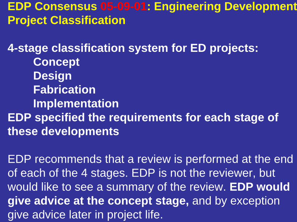
EDP Consensus 05-09-01: Engineering Development Project Classification
4-stage classification system for ED projects:ConceptDesignFabricationImplementation
EDP specified the requirements for each stage of these developments
EDP recommends that a review is performed at the end of each of the 4 stages. EDP is not the reviewer, but would like to see a summary of the review. EDP would give advice at the concept stage, and by exception give advice later in project life.
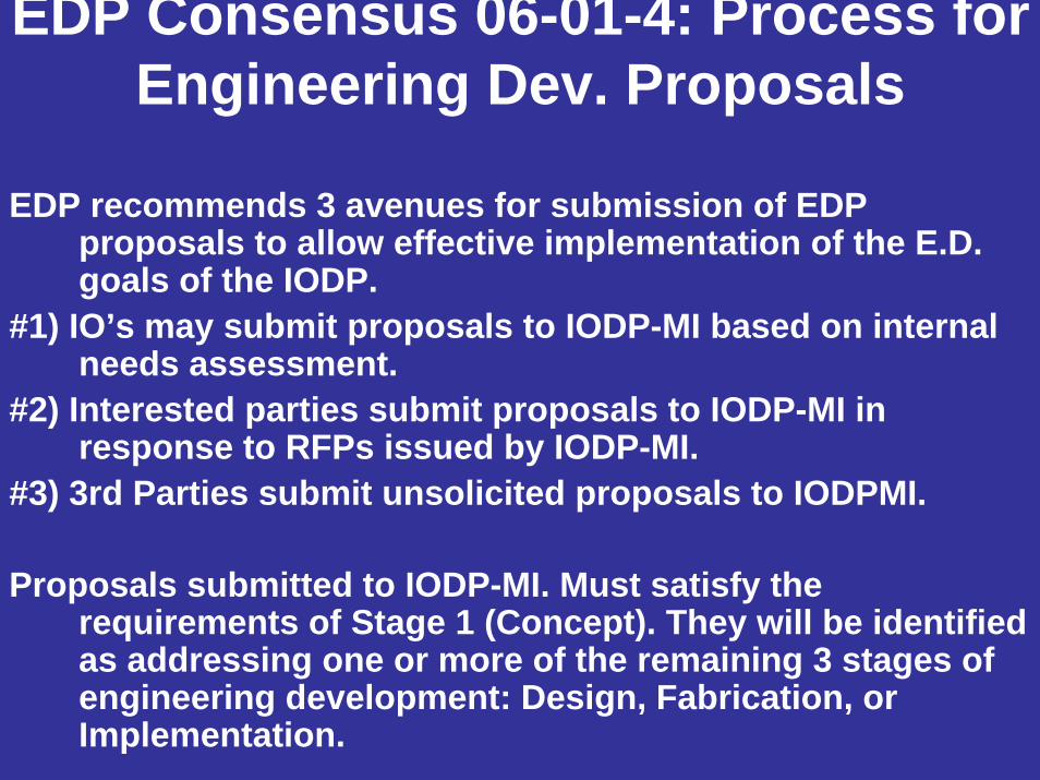
EDP Consensus 06-01-4: Process for Engineering Dev. Proposals
EDP recommends 3 avenues for submission of EDP proposals to allow effective implementation of the E.D. goals of the IODP.
#1) IO’s may submit proposals to IODP-MI based on internal needs assessment.
#2) Interested parties submit proposals to IODP-MI in response to RFPs issued by IODP-MI.
#3) 3rd Parties submit unsolicited proposals to IODPMI.
Proposals submitted to IODP-MI. Must satisfy the requirements of Stage 1 (Concept). They will be identified as addressing one or more of the remaining 3 stages of engineering development: Design, Fabrication, or Implementation.
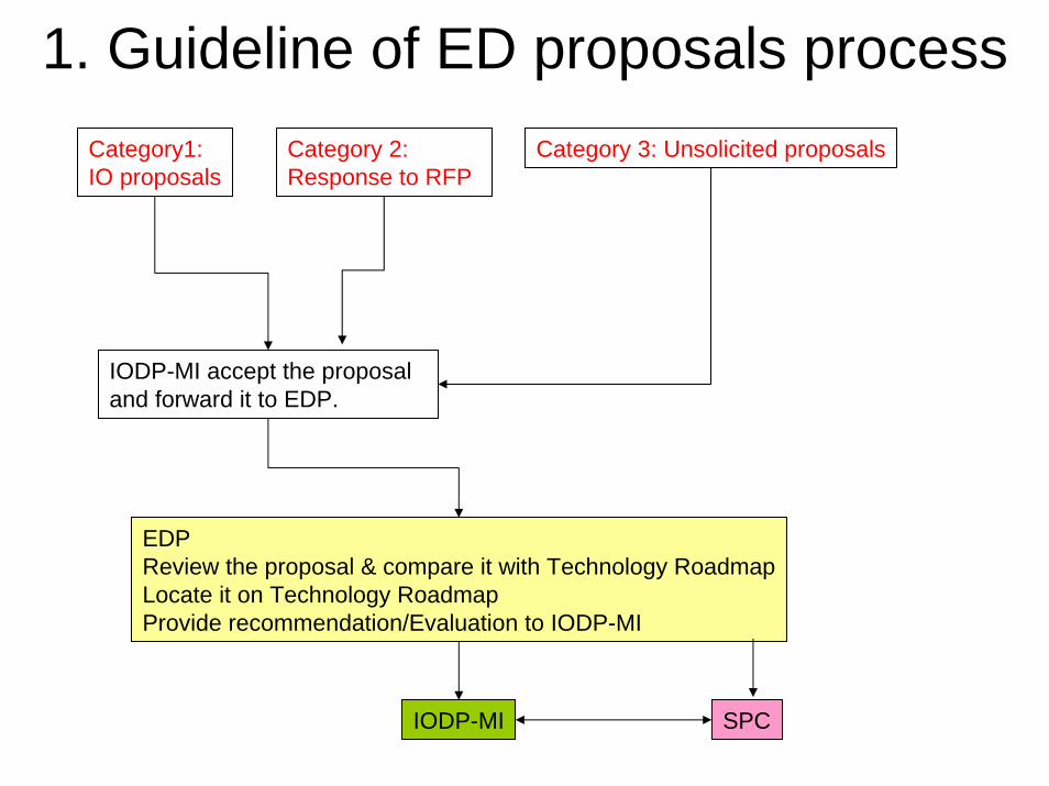
1. Guideline of ED proposals processCategory 3: Unsolicited proposals
IODP-MI
EDPReview the proposal & compare it with Technology RoadmapLocate it on Technology RoadmapProvide recommendation/Evaluation to IODP-MI
IODP-MI accept the proposal and forward it to EDP.
SPC
Category1:IO proposals
Category 2: Response to RFP
EDP Consensus 06-01-5EDP Role in Proposal Review Process
EDP recommends that IOPD-MI adopt a unified process to obtain EDP input on Engineering Development Proposals. EDP will review all Concept proposals. EDP will evaluate the proposal relative to the Engineering Development Roadmap or relative to achieving the goals of the ISP if the proposed development is not yet addressed in the Roadmap. The evaluation will assess how well the proposal meets established ED needs and provide a recommended course of action to SPC. In the event a Proposal does not address an established need, it will be evaluated with regards to its benefit to overall IODP-MI needs.

EDP Consensus 06-01-6: Technology Road Map
EDP begun development of a technology roadmap. The Technology Roadmap is a living document. EDP Members will work toward strengthening the Technology Roadmap between now and the June EDP Meeting
Technology teams:#1) Coring/logging/sampling, #2) Drilling/Vessel Infrastucture, #3) Borehole infrastructure
Teams charged with constructing the Technology Roadmap.A draft of the T.R. will be distributed to all one month prior to the June EDP Meeting. We will strive to release a first draft of the Technology Roadmap at the end of the next meeting.

EDP Consensus 06-01-3: USIO FY-07 Engineering
The USIO proposed to advance 2 Concept proposals on Feb. 10: 1) Logging while coring and 2) Telemetry.
Future Concept proposals (defined in Sept. 05 EDP Meeting #1 minutes) are expected 30 days before the EDP meeting. These two proposals are in a transition period and an exception will be made.
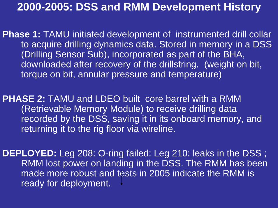
2000-2005: DSS and RMM Development History
Phase 1: TAMU initiated development of instrumented drill collar to acquire drilling dynamics data. Stored in memory in a DSS (Drilling Sensor Sub), incorporated as part of the BHA, downloaded after recovery of the drillstring. (weight on bit, torque on bit, annular pressure and temperature)
PHASE 2: TAMU and LDEO built core barrel with a RMM (Retrievable Memory Module) to receive drilling data recorded by the DSS, saving it in its onboard memory, and returning it to the rig floor via wireline.
DEPLOYED: Leg 208: O-ring failed: Leg 210: leaks in the DSS ; RMM lost power on landing in the DSS. The RMM has been made more robust and tests in 2005 indicate the RMM is ready for deployment.
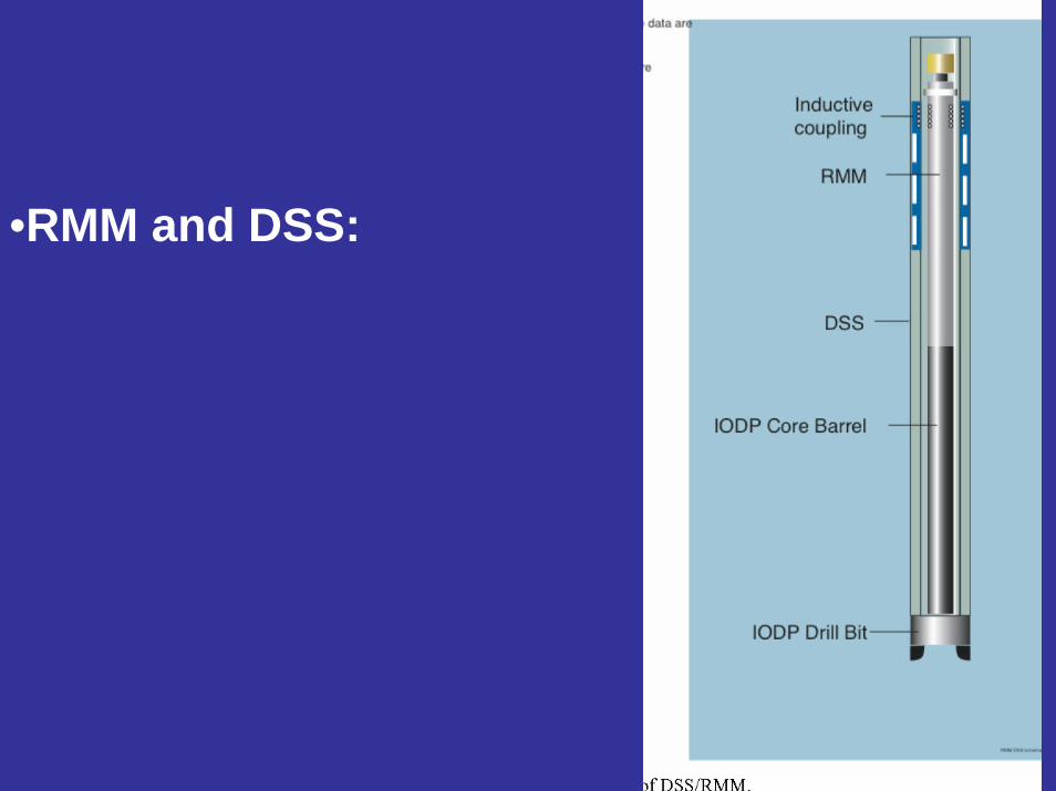
•RMM and DSS:
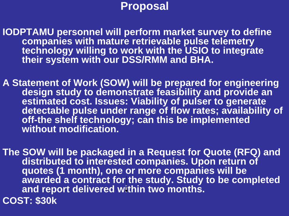
Proposal
IODPTAMU personnel will perform market survey to define companies with mature retrievable pulse telemetry technology willing to work with the USIO to integrate their system with our DSS/RMM and BHA.
A Statement of Work (SOW) will be prepared for engineering design study to demonstrate feasibility and provide an estimated cost. Issues: Viability of pulser to generate detectable pulse under range of flow rates; availability of off-the shelf technology; can this be implemented without modification.
The SOW will be packaged in a Request for Quote (RFQ) and distributed to interested companies. Upon return of quotes (1 month), one or more companies will be awarded a contract for the study. Study to be completed and report delivered within two months.
COST: $30k

•RMM and DSS: Fit to ISPallows driller to adjust drilling parameters.
Enhances drill string stability. Improves core recovery and quality.
Annulus pressure can identify unstable well conditions, guide well stabilization procedures, prevent serious operational difficulties.
EPSP: helps avoid well control problems (gas, water flow)
Heave compensation: can monitor effectiveness and may provide path toward the use of improved coring tools (e.g. diamond bit technology).

Proposal
Well-written proposal that meets the expectations of a Concept proposal. EDP Voted 6-3 in support and endorses proceeding.
• Strong support for the fit to ISP• Cost minor relative to cost of building • The true cost of building a functional device is
felt to be more than rough-quoted here. • Concern expressed over the fact that the DSS-
RMM has yet to prove successful. • The time frame (~3 months) may be too narrow
to achieve this.

USIO Engineering Proposal FY 07 Logging While Coring - Core Barrel
Build core tubes for use with logging while coring (LWC) equipment previously deployed on ODP Legs 204 and 209.
Next incremental step to make this technology ready for more routine use by all IODP platforms.
Addresses primary deficiencies of prototype LWC system by building a core tube designed to improving core quality and quantity.
$75,025 completion by July 2007
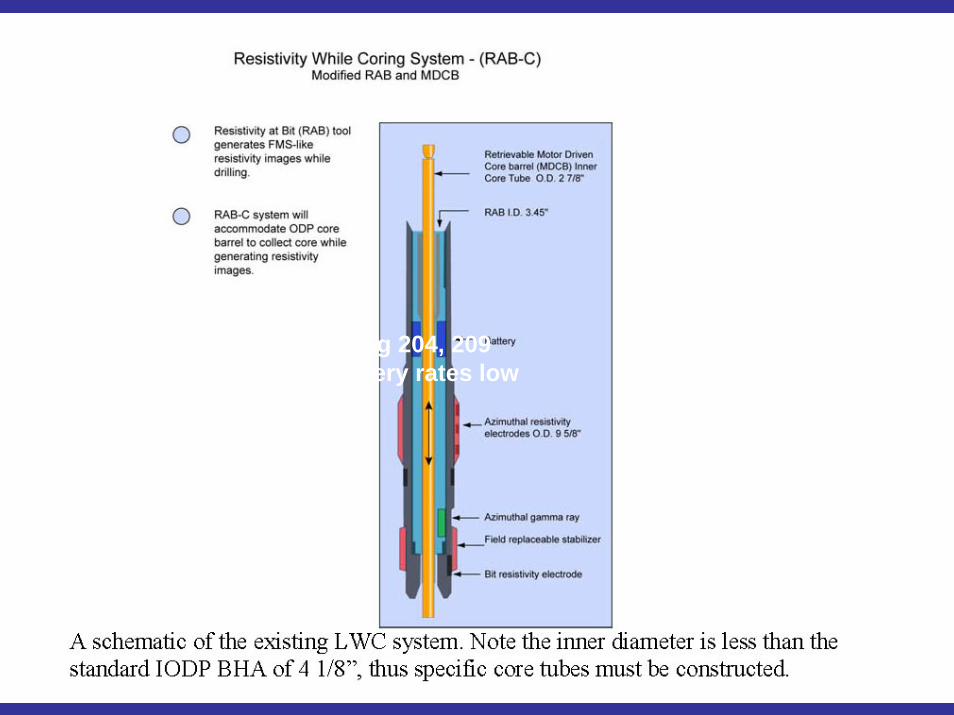
on ODP Leg 204, 209Core recovery rates low
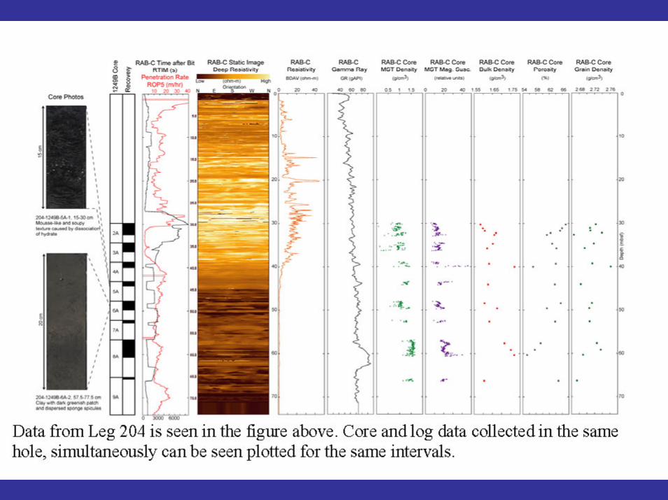
on ODP Leg 204, 209Core recovery rates low

ISPISP specifies establishing a “…program to maximize the links among IODP coring and sampling results, downhole measurements and observatory installations…“.
Better log-core-seismic tie.

HISTORY• joint effort between Lamont BRG, TAMU, Schlumberger
• Motor Driven Core Barrel (MDCB) system. Fabrication of cross-overs and drilling subs to integrate the RAB tool with the MDCB components.
• Successfully tested at on land facility
• Successfully deployed at sea to acquire resistivity images and ocean bottom sediment cores on Leg 204. The system was again used on Leg 209, but core recovery was poor.
• A working prototype that should not be considered for future deployments in IODP until dedicated core barrels are designed and fabricated for routine use in specific geologic environments.
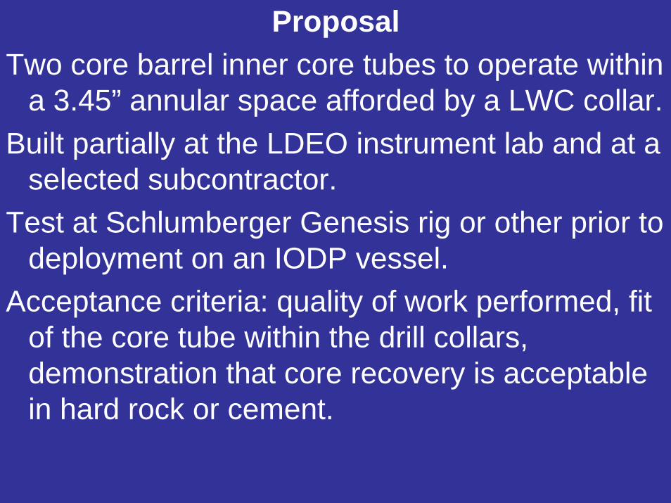
ProposalTwo core barrel inner core tubes to operate within
a 3.45” annular space afforded by a LWC collar. Built partially at the LDEO instrument lab and at a
selected subcontractor.Test at Schlumberger Genesis rig or other prior to
deployment on an IODP vessel.Acceptance criteria: quality of work performed, fit
of the core tube within the drill collars, demonstration that core recovery is acceptable in hard rock or cement.

USIO Engineering Proposal FY 07 Logging While Coring - Core Barrel
Solidly written proposal that meets the expectations of a Concept proposal. EDP Voted 6-3 in support and endorses proceeding. EDP Voted 7-2 in support and endorses proceeding.
• Good fit to ISP objectives. • Budget could be more detailed but is reasonable. • Incremental step in long term development• Panel members were varied in their confidence of
the success of achieving both high quality and high recovery
• Could have major impact if deployed on multiple platforms

APPENDIX 3

SPC Report to EDPWindischeschenbach, June 2006
1. Update on FY07-09 schedule development
2. March 2006 SPC Rankings for FY09/10
3. Brief review of programs at OTF for FY08+
4. Change of SPPOC to SASEC (SAS Executive Committee)
5. Update on planning for mission implementation

Development of FY07/08 Science Plan
• Late FY07 will mark initiation of Chikyu and Phase II SODV operations - but with only modest actual time in FY07
• OTF and SPC took this as an opportunity to advance the scheduling lead time beyond the timeline required by Lead Agencies for FY07 APP
• SPC made firm recommendations well into FY08 and projected SODV operations into FY09
• SPPOC formally approved this approach in January, and SPC/OTF will follow this path in future years

Summary FY07/08 Schedule Recommendationas of Oct 2005 SPC
July Aug Sept Oct Nov Dec Jan Feb March April May June July Aug Sept Oct4 1 2 3 4 1 2 3 4 1 2 3 4 1 2 3 4 1 2 3 4 1 2 3 4 1 2 3 4 1 2 3 4 1 2 3 4 1 2 3 4 1 2 3 4 1 2 3 4 1 2 3 4 1 2 3 4 1 2 3 4 1 2 3
SODV SODV SODV SODV SODVEquatorial T NanTroSEIZE NanTroSEIZE T TBN T Juan de FucaPacific Stage 1 riserless Stage 1 riserless
Chikyu Chikyu Chikyu ChikyuRiser training NanTro Riserless Drilling Testing & Maintenance NanTroSEIZE Riser Drilling
NT2-03 and NT3-01 NT2-03 -- 215 daysOther riserless?
FY 2007 FY 2008
- MSP: New Jersey Sea Level in FY07 (if not in FY06); FY08/09 program TBN after March 2006 SPC- Choice about “TBN” SODV slot at March 2006 SPC- SODV FY09: Canterbury Basin and Wilkes Land

Summary FY07/08 Schedule Recommendationas of Oct 2005 SPC
July Aug Sept Oct Nov Dec Jan Feb March April May June July Aug Sept Oct4 1 2 3 4 1 2 3 4 1 2 3 4 1 2 3 4 1 2 3 4 1 2 3 4 1 2 3 4 1 2 3 4 1 2 3 4 1 2 3 4 1 2 3 4 1 2 3 4 1 2 3 4 1 2 3 4 1 2 3 4 1 2 3
SODV SODV SODV SODV SODVEquatorial T NanTroSEIZE NanTroSEIZE T TBN T Juan de FucaPacific Stage 1 riserless Stage 1 riserless
Chikyu Chikyu Chikyu ChikyuRiser training NanTro Riserless Drilling Testing & Maintenance NanTroSEIZE Riser Drilling
NT2-03 and NT3-01 NT2-03 -- 215 daysOther riserless?
FY 2007 FY 2008
Since then, some modifications have occurred as a result of (a) rankings at March 2006 SPC and (b) June OTF meeting. Review the SPC rankings first...

March 2006 Proposals - for FY08/09 (I)• Still at SPC from prior rankings: [not actually ranked]
• 552-Full3 Bengal Fan
• 547-Full4 Oceanic Subsurface Biosphere
• [548-Full2 Chixculub K-T Impact Crater (MSP, to be revised)]
• 584-Full2 TAG II Hydrothermal
• 505-Full5 Mariana Convergent Margin
• [581-Full2 Late Pleistocene Coralgal Banks (MSP, to be revised)]
• 555-Full3 Cretan Margin
• [557-Full2 Storegga Slide Gas Hydrates (to be revised)]
• 666-APL2 SCIMPI Tool Development (w. Monterey Bay)
• Forwarded to SPC at May 2005 SSEP:
• 618-Full3 East Asian Margin (riser and MSP-riser?)
• 659-Full Newfoundland Rifted Margin (SODV)
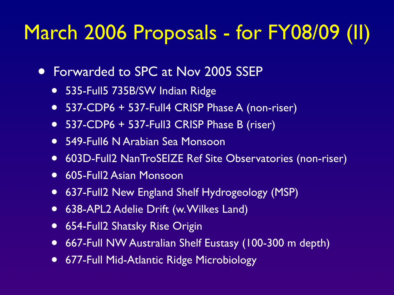
March 2006 Proposals - for FY08/09 (II)
• Forwarded to SPC at Nov 2005 SSEP
• 535-Full5 735B/SW Indian Ridge
• 537-CDP6 + 537-Full4 CRISP Phase A (non-riser)
• 537-CDP6 + 537-Full3 CRISP Phase B (riser)
• 549-Full6 N Arabian Sea Monsoon
• 603D-Full2 NanTroSEIZE Ref Site Observatories (non-riser)
• 605-Full2 Asian Monsoon
• 637-Full2 New England Shelf Hydrogeology (MSP)
• 638-APL2 Adelie Drift (w. Wilkes Land)
• 654-Full2 Shatsky Rise Origin
• 667-Full NW Australian Shelf Eustasy (100-300 m depth)
• 677-Full Mid-Atlantic Ridge Microbiology
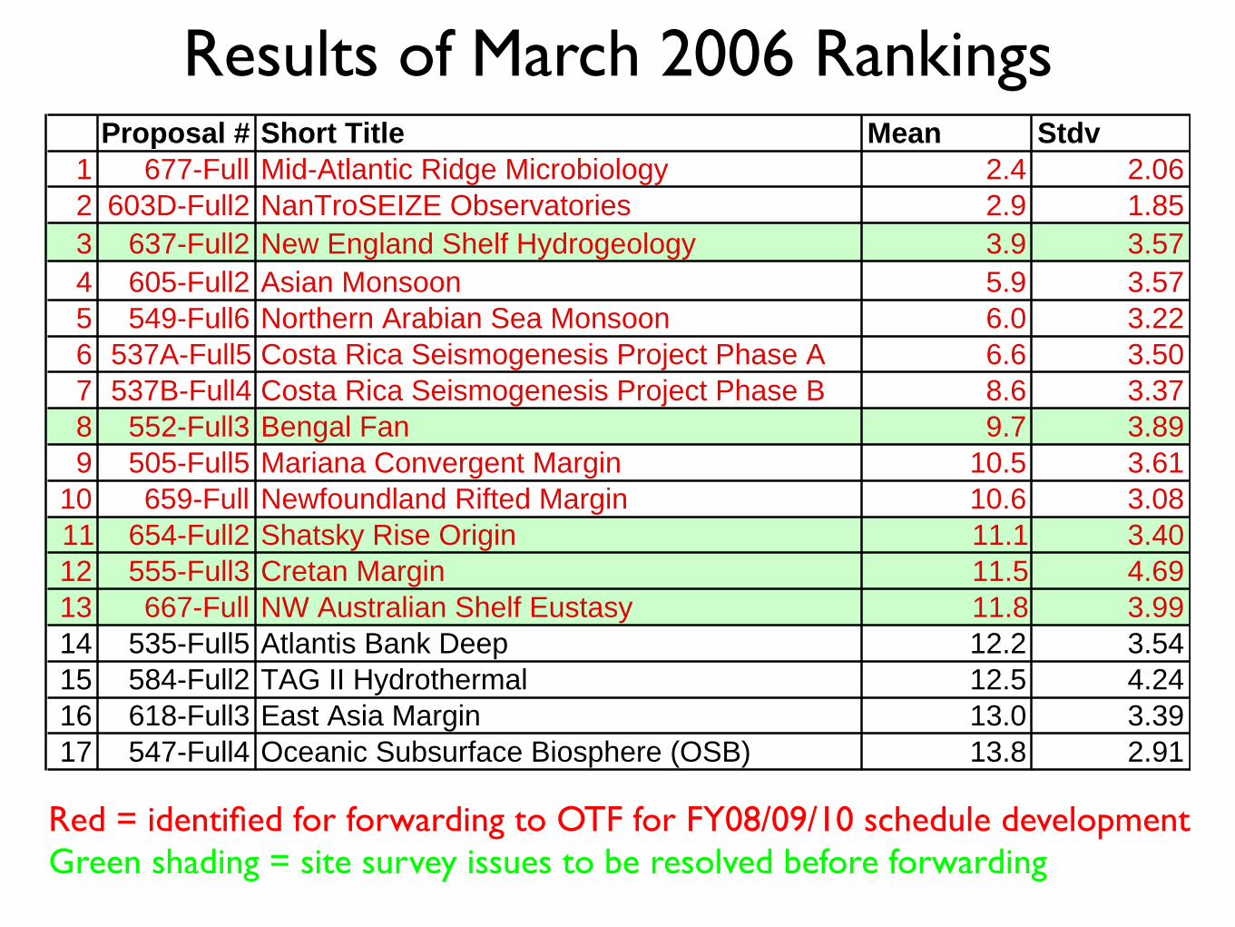
Proposal # Short Title Mean Stdv1 677-Full Mid-Atlantic Ridge Microbiology 2.4 2.062 603D-Full2 NanTroSEIZE Observatories 2.9 1.853 637-Full2 New England Shelf Hydrogeology 3.9 3.574 605-Full2 Asian Monsoon 5.9 3.575 549-Full6 Northern Arabian Sea Monsoon 6.0 3.226 537A-Full5 Costa Rica Seismogenesis Project Phase A 6.6 3.507 537B-Full4 Costa Rica Seismogenesis Project Phase B 8.6 3.378 552-Full3 Bengal Fan 9.7 3.899 505-Full5 Mariana Convergent Margin 10.5 3.61
10 659-Full Newfoundland Rifted Margin 10.6 3.0811 654-Full2 Shatsky Rise Origin 11.1 3.4012 555-Full3 Cretan Margin 11.5 4.6913 667-Full NW Australian Shelf Eustasy 11.8 3.9914 535-Full5 Atlantis Bank Deep 12.2 3.5415 584-Full2 TAG II Hydrothermal 12.5 4.2416 618-Full3 East Asia Margin 13.0 3.3917 547-Full4 Oceanic Subsurface Biosphere (OSB) 13.8 2.91
Results of March 2006 Rankings
Red = identified for forwarding to OTF for FY08/09/10 schedule developmentGreen shading = site survey issues to be resolved before forwarding
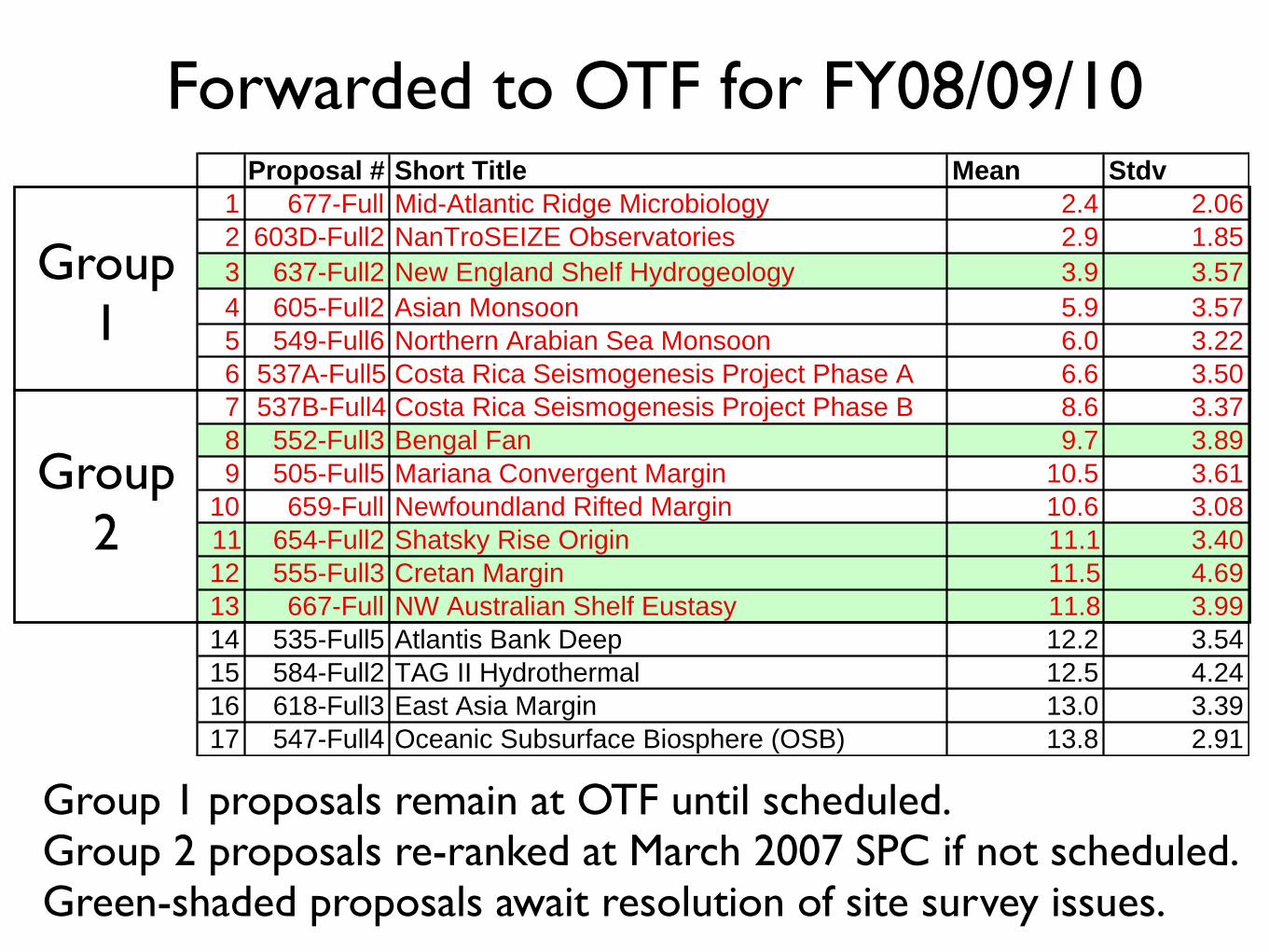
Proposal # Short Title Mean Stdv1 677-Full Mid-Atlantic Ridge Microbiology 2.4 2.062 603D-Full2 NanTroSEIZE Observatories 2.9 1.853 637-Full2 New England Shelf Hydrogeology 3.9 3.574 605-Full2 Asian Monsoon 5.9 3.575 549-Full6 Northern Arabian Sea Monsoon 6.0 3.226 537A-Full5 Costa Rica Seismogenesis Project Phase A 6.6 3.507 537B-Full4 Costa Rica Seismogenesis Project Phase B 8.6 3.378 552-Full3 Bengal Fan 9.7 3.899 505-Full5 Mariana Convergent Margin 10.5 3.61
10 659-Full Newfoundland Rifted Margin 10.6 3.0811 654-Full2 Shatsky Rise Origin 11.1 3.4012 555-Full3 Cretan Margin 11.5 4.6913 667-Full NW Australian Shelf Eustasy 11.8 3.9914 535-Full5 Atlantis Bank Deep 12.2 3.5415 584-Full2 TAG II Hydrothermal 12.5 4.2416 618-Full3 East Asia Margin 13.0 3.3917 547-Full4 Oceanic Subsurface Biosphere (OSB) 13.8 2.91
Forwarded to OTF for FY08/09/10
Group1
Group2
Group 1 proposals remain at OTF until scheduled.Group 2 proposals re-ranked at March 2007 SPC if not scheduled.Green-shaded proposals await resolution of site survey issues.

Mods to SODV Schedule - since March SPC
At June OTF meeting, USIO indicated that SODV target start date would be Nov 1 2007, not August 2007.
The current working model, to be approved at August SPC: - Equatorial Pacific Paleogene Transect I (626-Full2) - NanTroSEIZE Stage 1 (603A, B, C) - NanTroSEIZE Stage 1 continued (603A, B, C) - Bering Sea Paleoceanography (477-Full5) - Juan de Fuca Flank Hydrogeology III (545-Full3) - Equatorial Pacific Paleogene Transect II (626-Full2) - Canterbury Basin (Proposal 600-Full) - Wilkes Land Margin (Proposals 482-Full3, 638-APL2)
Several options for FY09 into FY10

Already at OTF
477-Okhotsk/Bering - Bering FY08?
553-Cascadia II
589-GoM II 595-Indus/Murray
Forwarded March 2006
549-N. ArabianSea Monsoon
659-Newf. Rifted Margin
677-MAR Microbio
537A - CRISP(non-riser)
505-MarianaConv. Margin
605-AsianMonsoon
621-Monterey603D-NTS Obs’y

Replacement of SPPOC by SASEC
• SPPOC was chartered both as SAS Executive Authority and as a committee of the IODP-MI Board of Governors (BoG)
• At its April 1 meeting, the IODP-MI BoG approved a motion to replace SPPOC with a smaller SAS Executive Committee (SASEC)
• SPPOC was then formally disbanded
• SASEC membership nominations solicited for May 15, aiming for initial meeting July 11-12 (when SPPOC had been scheduled)
• SASEC mandate is very similar to that of SPPOC, except that BoG proposed a voting membership of 8, those being 2 from IODP-MI BoG (1US, 1Japan), then 2 each from US, Japan, and ECORD
• At Lead Agencies request, this changed to 3:3:2 ratio for member appointees, keeping membership of SAS Executive Committee proportional as in Memoranda for all SAS committees and panels

Brief Update on Mission Implementation Plan (I)
• Small Group incorporated the very useful feedback from Nov SSEP in its report submitted to January SPPOC meeting.
• SPPOC thought mission implementation plan in Small Group report was too complicated, and formed its own ad hoc working group (S. Humphris, chair) to develop a simpler implementation plan for approval by March SPC and April 1 IODP-MI BoG.
• After presentation at SPC, that working group report and plan were modified considerably, then approved by SPC and SPPOC in late March, then IODP-MI BoG on April 1.
• That plan included formation of a third small ad hoc group to develop a method to integrate mission planning into the “normal” proposal process, with one member each from SPPOC, SPC, SSEP, and IODP-MI. Final plan to be ready for approval at August SPC.
• But, BoG then dissolved SPPOC - so process is waiting on formation of SASEC and nomination of one its members to third WG...

Missions: Definition and Clarification(KB at SSEP meeting, May 2006)
• Approved definition: “A Mission is an intellectually integrated and coordinated drilling strategy originating from the scientific community that (a) addresses a significant aspect of an IODP Science Plan theme on a global basis over an extended period of IODP, and (b) merits urgent promotion in order to achieve overall IODP program goals.”
➡ Clarification in SPPOC WG report: Missions are not the same as CDP’s...missions can encompass more than one CDP.
➡ KB Interpretation: Missions are almost equivalent to ISP Initiatives or equally important new IODP science themes, selected for particular emphasis in order to achieve program goals. In the mission definition, “on a global basis” might also be interpreted as “of global significance.”

Brief Update on Mission Implementation Plan (II)
• The approved SPPOC working group plan also specified an accelerated, one-time process this year, leading to designation of initial ~2 missions and their mission teams.
• That process started at late May SSEP meeting, when SSEP considered existing proposal pressure and ISP Initiatives, and recommended two potential initial missions for consideration at August SPC meeting:
• Seismogenic Zone - NanTroSEIZE, CRISP, plus new Sumatra proposal and other possible locations (Cascadia?)
• A global change/carbon cycling mission combining elements of 3 ISP initiatives (Extreme Climates, Rapid Climate Change, LIPs), possibly entitled “Global Carbon Cycling and Climate Change: Testing the IPCC Report”
• In future, SSEP also liked utilizing community-wide workshops to develop proposed new mission approaches.

APPENDIX 4

INTEGRATED OCEAN DRILLING PROGRAMMANAGEMENT INTERNATIONAL
FY06 FY06 IODPIODPEngineeringEngineering DevelopmentDevelopment
Updates from Updates from IODP-MIIODP-MI
Engineering DevelopmentEngineering Development PanelPanelWindischeschenbachWindischeschenbach, Germany, Germany
June 27-29, 2006June 27-29, 2006

INTEGRATED OCEAN DRILLING PROGRAMMANAGEMENT INTERNATIONAL
DiscussionDiscussion ItemsItems
•• Annual Program Plan DevelopmentAnnual Program Plan Development•• Review TaskReview Task Force Items for ED RoadmapForce Items for ED Roadmap•• FY06 Engineering Development StatusFY06 Engineering Development Status
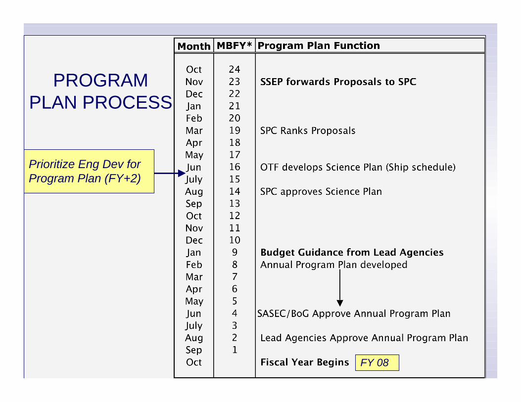
INTEGRATED OCEAN DRILLING PROGRAMMANAGEMENT INTERNATIONAL
Prioritize Eng Dev for Program Plan (FY+2)
FY 08
PROGRAMPLAN PROCESS

INTEGRATED OCEAN DRILLING PROGRAMMANAGEMENT INTERNATIONAL
Review of Expedition OperationsReview of Expedition OperationsOct 2004Oct 2004 ACEXACEX - 302- 302Dec 2004:Dec 2004: Juan de Juan de Fuca Fuca Hydrogeology - 301Hydrogeology - 301
Aug 2005: Aug 2005: Oceanic Core Complex - 304/305Oceanic Core Complex - 304/305
Feb 2006:Feb 2006: North Atlantic ClimateNorth Atlantic Climate - 303/306- 303/306Porcupine Carbonate MoundsPorcupine Carbonate Mounds - 307 - 307
May 2006:May 2006: Gulf of Mexico Hydrogeology - 308Gulf of Mexico Hydrogeology - 308Jun 2006:Jun 2006: Superfast Superfast Spreading Crust - 309/312Spreading Crust - 309/312Aug 2006:Aug 2006: Tahiti Sea Level - 310Tahiti Sea Level - 310Fall 2006:Fall 2006: Cascadia Cascadia Gas Hydrates - 311Gas Hydrates - 311

INTEGRATED OCEAN DRILLING PROGRAMMANAGEMENT INTERNATIONAL
Items ForItems For Engineering RoadmapEngineering Roadmap•• SODV SODV issuesissues
Rig Instrumentation SystemRig Instrumentation System Active HeaveActive Heave CompensationCompensation Subsea Subsea VisualizationVisualization
•• Coring ToolsCoring Tools Magnetic OverprintMagnetic Overprint Geotechnical ToolsGeotechnical Tools Deep Drilling ImprovementsDeep Drilling Improvements Core LinersCore Liners
•• Downhole Downhole ToolsTools DVTPP DVTPP / / Colletted Colletted Delivery SystemDelivery System Prioritization for future developmentPrioritization for future development

INTEGRATED OCEAN DRILLING PROGRAMMANAGEMENT INTERNATIONAL
Items For Items For EDP EDP RoadmapRoadmap
SODV SODV IssuesIssues• USIO to improve Rig Instrumentation System sensor reliability and data
access (301); w/ accurate depth/time base for RIS (308)
• USIO to replace of current subsea camera and image capture system (301);consider lease/purchase of through-the-pipe camera system (301)
• The USIO and IODP-MI to review the continued support of active heavecompensation as part of the SODV planning process (304/305)

INTEGRATED OCEAN DRILLING PROGRAMMANAGEMENT INTERNATIONAL
Items For Items For EDP EDP RoadmapRoadmapCoringCoring ToolsTools
Magnetic Overprint IssuesMagnetic Overprint Issues•• EDP EDP investigate cause of magnetic overprinting of cores and examine options toinvestigate cause of magnetic overprinting of cores and examine options to
reduce the effect of overprinting (303/306/307; 309/312)reduce the effect of overprinting (303/306/307; 309/312)
Geotechnical Tools• IODP-MI to provide USIO with details regarding geotechnical coring tools that do
not require modification for deployment from the SODV (308)

INTEGRATED OCEAN DRILLING PROGRAMMANAGEMENT INTERNATIONAL
Items For Items For EDP EDP RoadmapRoadmapCoringCoring Tools Tools (cont)(cont)
Core LinersCore Liners• The USIO is encouraged to work with Transocean/ODL Core Technicians to
examine APC coring tools, equipment, and statistics (sea state, lithology, waterdepth, etc.) associated with operations resulting in shattered liners and worktoward a better understanding of the root causes of liner collapse. Thedevelopment of database containing the statistics of this study is highlyrecommended (303/306/307).
Other• IODP-MI to work with IO’s, Industry, and Science Advisory Structure (EDP, STP)
to investigate and prioritize avenues for developing increased coring/drillingcapability for deep-drilling programs. Areas of investigation should includenew/different bit technology and Fast Drill process (309/312)

INTEGRATED OCEAN DRILLING PROGRAMMANAGEMENT INTERNATIONAL
Items For Items For EDP EDP RoadmapRoadmapDownhole Downhole ToolsTools
IODP-MI to investigate (1) concepts to effectively decouple the drillstring from theDVTPP and T2P, and (2) the refurbishing of the existing CDS as possibilities towardmaking the CDS more efficient (308)
USIO to conduct a study to examine the scale of problem associated with seawaterleaks in the DVTPP and report the results of the study to Engineering DevelopmentPanel (EDP). Depending on the results of this study, EDP to makerecommendations to the USIO and IODP-MI on how to proceed with a solution (308)
EDP prioritatization of dowhole tool needs: 3-component magnetometer, high-3-component magnetometer, high-temperature fluid sampling tools, others? (309/312)temperature fluid sampling tools, others? (309/312)

INTEGRATED OCEAN DRILLING PROGRAMMANAGEMENT INTERNATIONAL
FY06 Engineering Development ProjectsFY06 Engineering Development ProjectsInitially Submitted by Initially Submitted by IOsIOs
USIOPulsed Telemetry Module ($175,000) —Real-time, at-the-bit drilling
dynamics data to the driller. Integrating a commercial, retrievablePTM with IODP’s existing MWD tool.
Common Bottom-Hole Assembly (BHA) ($250,000)—Develop a commonBHA with interchangeable coring systems to replace the two ODPBHAs.
CDEXLong-Term Monitoring system ($175,000) - Feasibility study for the
development of a standard long-term monitoring systeminfrastructure.

INTEGRATED OCEAN DRILLING PROGRAMMANAGEMENT INTERNATIONAL
FY06 Engineering DevelopmentFY06 Engineering DevelopmentPulsed Telemetry Module ($175,000)
Real-time, at-the-bit drilling dynamics data to the driller. Integrating acommercial, retrievable PTM with IODP’s existing MWD tool.
EDP EDP Consensus 05-09-03:We support IODP-MI acquiring the pulsed telemetry module asdescribed in the proposal; presented by the USIO. Although, theproposal does not meet the requirements of the recently definedstages of an engineering development proposal (EDP Consensus05-09- 01), the EDP felt it contained sufficient information forevaluation and given the short timeframe, felt it worth going forward.
Status-Approved/Funded by IODP-MI & L.A. for FY06-USIO requested to move to FY07 and reduce scope

INTEGRATED OCEAN DRILLING PROGRAMMANAGEMENT INTERNATIONAL
FY06 Engineering DevelopmentFY06 Engineering DevelopmentCommon Bottom-Hole Assembly (BHA) ($250,000)
Develop a common BHA with interchangeable coring systems to replacethe two ODP BHAs.
EDP EDP Consensus 05-09-04Consensus 05-09-04:There is not enough information in this proposal to decide whether itThere is not enough information in this proposal to decide whether itmerits moving ahead. If the proponents complete a conceptualmerits moving ahead. If the proponents complete a conceptualengineering proposal (defined in EDP Consensus 05-09-01), EDPengineering proposal (defined in EDP Consensus 05-09-01), EDPwould be interested in considering it.would be interested in considering it.
StatusNot submitted in final FY06 Annual Program Plan

INTEGRATED OCEAN DRILLING PROGRAMMANAGEMENT INTERNATIONAL
FY06 Engineering DevelopmentFY06 Engineering DevelopmentLong-Term Monitoring system ($175,000)
Feasibility study for the development of a standard long-term monitoringsystem infrastructure.
EDP EDP Consensus 05-09-05:Consensus 05-09-05:The EDP recommends that CDEX’s FY06 proposal to IODP-MI besupported. Within the context of EDP Consensus 05-09-01, thisproposal exceeds the expectations of a Conceptual Proposal (Stage1). The EDP recommends that the IDOP-MI participate in theArchitecture Peer Review scheduled by CDEX for Q1 FY06.
Status-Approved / Funded by IODP-MI & L.A. in FY06 Annual Program Plan-In Progress:

INTEGRATED OCEAN DRILLING PROGRAMMANAGEMENT INTERNATIONAL
FY06 Engineering DevelopmentFY06 Engineering DevelopmentLong-Term Monitoring System
Specific FY06 Project -- TwoSpecific FY06 Project -- Two part feasibility study:part feasibility study:
(1) Complete the System Architecture Design(1) Complete the System Architecture Design•• Science & Technical RequirementsScience & Technical Requirements
Seismic Observations ,Seismic Observations ,Geodetic Observations, Geodetic Observations, Temperature Monitoring,Temperature Monitoring, Pressure Monitoring, Pressure Monitoring, Electromagnetic Observations, Electromagnetic Observations, Osmo Osmo SamplingSampling
•• Basic ComponentsBasic Components Telemetry,Telemetry, Sensor Sensor Downhole Downhole Modules, SeabedModules, Seabed module (power, datamodule (power, data
recorder, interfaces,recorder, interfaces, etc)etc)
•• Conceptual Prototype Conceptual Prototype

INTEGRATED OCEAN DRILLING PROGRAMMANAGEMENT INTERNATIONAL
FY06 Engineering DevelopmentFY06 Engineering DevelopmentLong-Term Monitoring System
Specific FY06 Project -- TwoSpecific FY06 Project -- Two part feasibility study:part feasibility study:
(2) Complete High Level Design(2) Complete High Level Design•• Detailed Specifications and costs Detailed Specifications and costs
•• System Topology System Topology•• Telemetry Telemetry•• Power Consumption Power Consumption•• Sensor Interfaces Sensor Interfaces•• Data Storage Data Storage DesignDesign•• Deployment and maintenance Deployment and maintenance
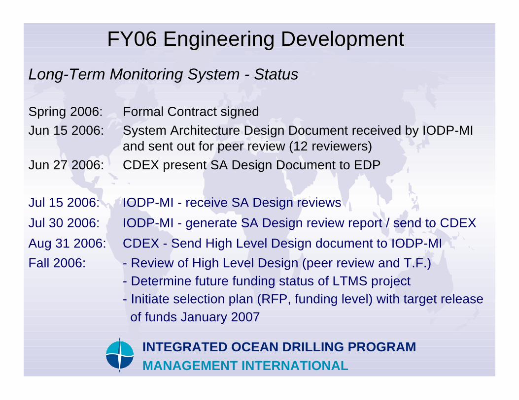
INTEGRATED OCEAN DRILLING PROGRAMMANAGEMENT INTERNATIONAL
FY06 Engineering DevelopmentFY06 Engineering DevelopmentLong-Term Monitoring System - Status
Spring 2006: Formal Contract signedJun 15 2006: System Architecture Design Document received by IODP-MI
and sent out for peer review (12 reviewers)Jun 27 2006: CDEX present SA Design Document to EDP
Jul 15 2006: IODP-MI - receive SA Design reviewsJul 30 2006: IODP-MI - generate SA Design review report / send to CDEXAug 31 2006: CDEX - Send High Level Design document to IODP-MIFall 2006: - Review of High Level Design (peer review and T.F.)
- Determine future funding status of LTMS project- Initiate selection plan (RFP, funding level) with target release of funds January 2007
INTEGRATED OCEAN DRILLING PROGRAMMANAGEMENT INTERNATIONAL

APPENDIX 5
ICDP/SAFOD MonitoringApproaches (“down-hole”)
Lessons learned from ICDP projects
B.Prevedel, ICDP-OSG, GFZ-Potsdam

ICDP/OSG – Perm.Monitoring
• Part of the Operations Service Group (OSG)– Drilling engineering and operations supervision– Wireline logging– Drilling data management– Training– Permanent monitoring
• Design monitoring arrays• Liaise with PEs and suppliers/manufacturer• Project management & field installations
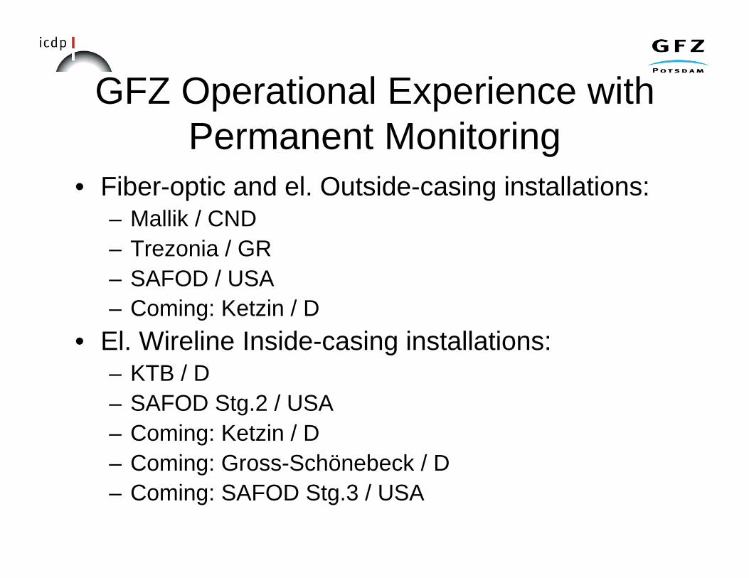
GFZ Operational Experience withPermanent Monitoring
• Fiber-optic and el. Outside-casing installations:– Mallik / CND– Trezonia / GR– SAFOD / USA– Coming: Ketzin / D
• El. Wireline Inside-casing installations:– KTB / D– SAFOD Stg.2 / USA– Coming: Ketzin / D– Coming: Gross-Schönebeck / D– Coming: SAFOD Stg.3 / USA

Planning the Monitoring Task

Depthmeters
4096SAFMH SAFMH
2048 BASEL LVEWSAFPH
1024 TDPA
512 BASELSAFVA
256 MONTY PARK PBOPALM
128 COSOKRAFLA KRAFLA GEYSERS
64 ORO-QH
32 PUNA PUNA
16
4
2
1 PUNA PALM LOMA KRAFLA LV97 SAFDBS
1 2 4 8 16 32 64
No. of stations
Statistics Locations Tomography
Source Rupture Propagation
Seismotectonics
Fault Structure
EQ Physics
Research Objectives: Selecting the play field

What signal are we looking for?Depth
meters1 Hz 10 Hz 100 Hz 1000
4096+ +
2048
1024
512
256
128
64
32
16Signal-to-Noise gain lost
4 mainly to scattering & attenuation
2
11 2 4 8 16 32 128 256 512
Signal Improvement
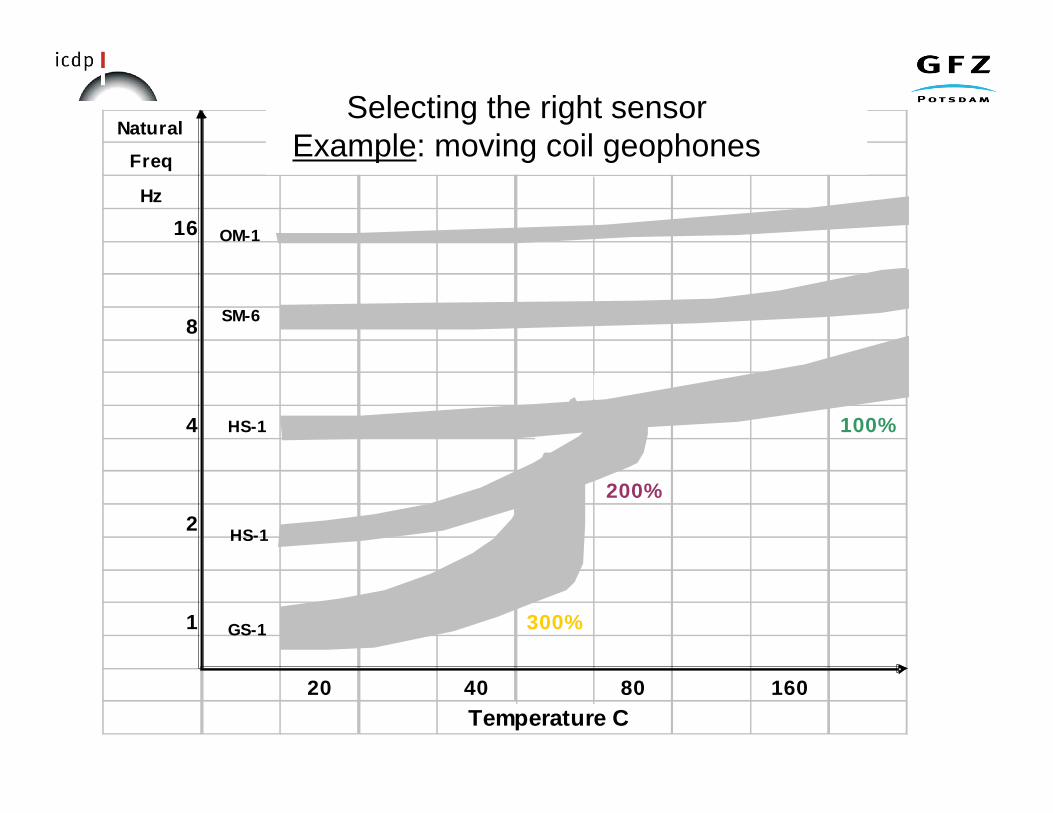
Natural "HIGH TEMPERATURE" LEAF SPRING SEISMOMETERSFreq (VERTICAL)Hz
16
8
4 100%
200%2
1 300%
20 40 80 160Temperature C
GS-1
HS-1
HS-1
SM-6
OM-1
Selecting the right sensorExample: moving coil geophones

Permanent DH Monitoring Stategies
FO-DTS/Press cable Casing centralizer/cable protector Wellhead
1.) Outside casing cemented cabes & sensors (OCA)– fibre-optic cable (distributed temperature, pressure)– analogue el. cables (Resistivity, seismometer, pressure)=> cable outlet @ wellhead, installation survival.

Permanent DH Monitoring Stategies
2.) Inside casing semi-permanent tools (ICA)– fiber/electrical armored wire-line cable (digital
seismometer, tiltmeter, accelerometer, otherlogging tool equivalent sensors)
– Poor cable survival, anchoring quality, systemredundancy, temperature stability.
1. Outside casing cemented cabes & sensors (OCA)- fibre-optic cable (distributed temperature, pressure)
- analogue el. cables (Resistivity, seismometer, pressure)⇒ cable outlet @ wellhead, ruggedness, sensor stability
Details at Details at posterposter: Prevedel, : Prevedel, KückKück//GFZ-PotsdamGFZ-Potsdam

Comparison Array TechnologyOCA:• Non-powered analogue sensors
with excellent life• High temp. & pressure survival
with no drift (FO)• Leaves well internally free for
other operations• Requires complex cable outlet at
the well-head• Sometime limited bandwidth and
sensitivity (today)• Cost effective• Sensors are all analogue typically
covering: pressure, temperature(DTS), strain and acceleration withexcellent coupling to the formation
=> Fiber optic is emerging
ICA:• High power consumption instrument
with excellent signal fidelity• High temp. & pressure survival with
significant long-term drift• High-end (expensive) active sensor
technology from logging available• No other well operation possible• Easy access in/out of the well• No data redundancy (acq./telemetry)• Susceptible to gas/corrosion attacks• Frequent cable failure• Problematic anchoring to the
borehole wall
=> Digital electric is mature

Sea Level5 km
10 km
5 10 15 20 25 30 40 km
San Andreas FaultObservatory At Depth
(SAFOD)
• Permanent MonitoringObjectives:– Passive seismics: 3c
Seismometers and 3cAccelerometers (DC – 1800 Hz)
– Geomechanical: Tiltmeter andStrainmeter
– Geochemical: downhole sample– Environmental: pressure,
temperature• Project phases:
– Stage1: analogue array in PH– Stage2: digital 3 level in MH for
core targets– Stage3: digital 5 level in MH for
long-term observatory

SAFOD Status (06/2006)Problem Analysis
• Well status:– Borehole stability problems in 8 ½“
hole– 800 ft deviated SAF section @ 60
degree• 20“ cave-outs over entire SAF
traverse section• Improper 7“ cementation leading to
gas channeling• Dented casing (6 mm) at 11 k ft
• Tool performance:– Gas influx into monitoring
instrumentation– Cable corrosion and leakage– Unstable wall anchoring of
instrumentation– Max. instrument survival = 2 weeks

SAFOD Stage-3 (Sept.2007)Long-term Monitoring Solution
• Philosophy:– Accept dynamic behavior of the well– Pipe conveyed deployment of permanent array– Retrievability option of the array for upgrade
• Solution:– 5 level, fixed mounted seismometer array– One production packer for isolation of OH section– Pessure/temperature sensor in core hole section– Defined environment inside the deployment pipe string
• Organization:– GFZ in the project coordinator– Pinnacle Technology is the general contractor
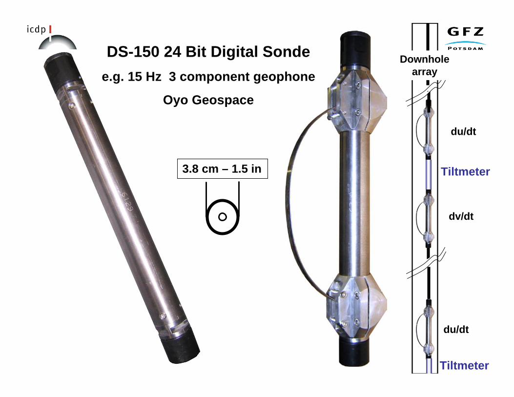
3.8 cm – 1.5 in
DS-150 24 Bit Digital Sondee.g. 15 Hz 3 component geophone
Oyo Geospace
dv/dt
du/dt
du/dt
Downholearray
Tiltmeter
Tiltmeter

Some Lessons Learned Along the Road to Seismology in the Source
Lesson: The Do’s, Don’ts, and Maybe’s
Do’s Maybe’s Don’ts
Triple fluid barriers Double fluid barriers Single fluid barrier
Welded seals Metal-metal seals O-ring seals
clamping/weight>>1 clamping/weight >1 clamping/weight ~1
Passive clamps Hydraulic ram clamps Electrical ram clamps
Passive FO/Cu cable Single power cable Multiple power cable
Armor+jacket+fill cable Jacket+fill cable jacket cable
Passive sensors Low power sensors High power sensors electrically isolated case grounded case downhole ground for High Temp & Press for Mid Temp & Press for Low Temp & Press > 150 C ~ 150 C < 100 C > 3 km ~ 3 km < 3 km Special winch Used winch Donated winch Internat. Institutes & Ind. Nat. Institutes & Industry Local Univ. & Industry

Special Thanks to:
SAFOD, PARKFIELD, LONG VALLEY & OTHER WORKING GROUPS
&
PETER MALIN, EYLON SHALEV, & STUDENTS

APPENDIX 6

CDEX Technology Development Roadmap
Prepared for
Engineering Development Panel MeetingJune 27-29, 2006 WindischescheSnbach, Germany
June 27, 2006

CHIKYU current status and future schedule
1. ~August 2007 (until Internal operation)Shakedown cruise SIT (system Integration Tests)
2. September 2007~ (International operation)NanTroSEIZE phase 1 2007
phase 2 Riser drilling ~3.5 km 2008phase 3 deeper drilling


Table2 CHIKYU Drilling Condition
2.5kt1.5kt1.5ktCURRENT
5.5m5.5m4.5mWAVE(significant)
23 m/s30 m/s23 m/sWIND(1min. average)
Stand-by 2Stand-by 1NormalDrilling

Possible timeline
OperationsYear
Stage 4: Install long-term systemsin riser holes2012 (?)
Record short-term boreholearrays; finalize long-termmonitoring packages
2010 / 2011
Stage 3: NT3-01 deep riser drilling2009 / 2010
Stage 2: first riser drilling atmega-splaymid - late 2008
Stage 1: riserless at 6 sites2007 - mid 2008

1. ~August 2007 (until Internal operation)Shakedown cruise SIT (system Integration Tests)
DPSBOP tests etc.

2. September 2007~ (International operation)NanTroSEIZE phase 1 2007
phase 2 Riser drilling ~3.5 km 2008phase 3 deeper drilling
Riser drilling under strong Kuroshio currentCoring in fault zoneLong Term Borehole Monitoring

IODP Initial SciencePlan includes theSeismogenic ZoneInitiative as a high
priorityIODP is an international science
project to study the planet belowthe oceansUSAJapan18 other countries

Drilling Vessel ChikyuWill be operated by Japan as part ofinternational IODP effort
Completed in 2005 at cost of nearly$600 million
Scientific drilling begins in 2007
Elevation above waterline:
112 meters
370 feet
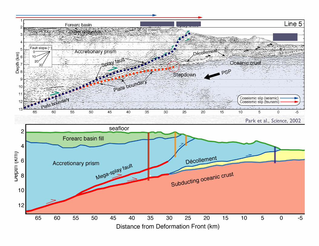
Park et al., Park et al., ScienceScience, 2002, 2002
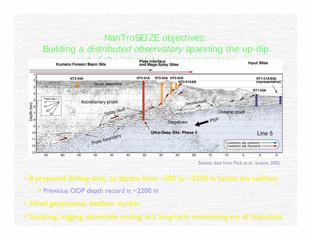
NanTroSEIZE objectives:Building a distributed observatory spanning the up-dip
end of the interplate seismogenic zone
•• 8 proposed drilling sites, to depths from ~500 to ~5500 m below the seafloor8 proposed drilling sites, to depths from ~500 to ~5500 m below the seafloor
Previous ODP depth record is ~2200 mPrevious ODP depth record is ~2200 m
•• Allied geophysical, seafloor studiesAllied geophysical, seafloor studies
•• Sampling, logging, Sampling, logging, downhole downhole testing, and long-term monitoring are all importanttesting, and long-term monitoring are all important
Seismic data from Park et al., Seismic data from Park et al., ScienceScience, 2002, 2002

Y
Heat Flow Data and Model of Thermal StructureHeat Flow Data and Model of Thermal Structure
Ashi et al., 1999
M. Yamano and K.Wang, unpublishedresults
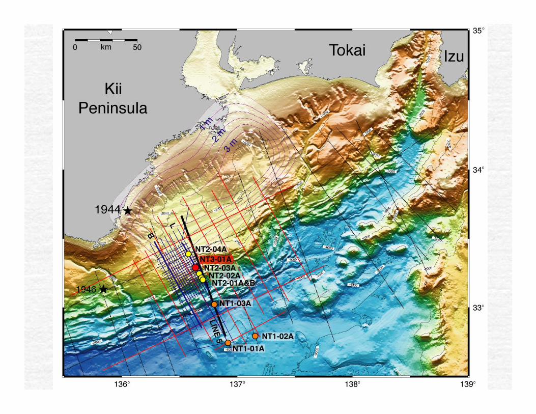

Stage 1 Expedition PlanChikyu Expedition #1
LWD-only drilling at all Stage 1 sites
Chikyu Expedition #2NT2-03 Pilot Hole
Chikyu Expedition #3Fault Zone Drilling at Prism Toe and Splay Faults
US Riserless Vessel Expedition #1Incoming Plate Reference Sites
US Riserless Vessel Expedition #2NT3-01 (Planned Deep Site) Kumano Basin section drilling and CORK

Pilot Observatory ObjectivesDocument strain accumulation and release
Quantify amount of present-day plate boundarymotion accommodated on Mega-Splay vs. deepdecollement.
Link strain to microseismicity and hydrologictransients
Document ambient pore fluid pressure
Measure in situ temperature gradients
Observatory Elements: multi-level pore pressure,strainmeter, BB seismometer, short periodseismic array (?).

NanTroSEIZE Stage 2
• 4 sites: 3 riserless, 1 riser-based (NT2-03)
• NT1-01 and NT1-06: core and log 100 m basement; install monitoringpackage
• Monitoring system at NT2-01A to monitor pore pressure while drillingNT2-01B, conducting active hydrological test

NanTroSEIZE Stage 3
• 2 sites, one riserless, one riser-based (plus possible NT2-02 if it remains high priority)
• NT1-03: Deepen to 1200 m if results of Stage 1 indicate this will be needed to define up-dip end of decollement system
• NT3-01: Drill deep riser 6000 m site – LWD, core, deploy preliminary monitoring system

Megathrust SiteObservatory:
Fault Zone Monitoring
5500 to 6000 m below sea floorHeavy use of Logging While Drilling,coring in key zones
Sidetrack above mega-splay and core2nd crossing of faults
Active hydrological/stress experiments(hydraulic fracture tests)
Completion - Install ObservatoryMultiple perforated, packer isolatedintervalsMultiple sensor stringsLong-term fluid sampling (?)Real-time data transmission via proposedsea floor cable network

Towards the Development of an Ocean-bottom Network System againstLarge-Magnitude, Ocean-trench Earthquakes and Tsunami
Infrastructure Plans from FY2006~2009
Kii Peninsula
Shionomisaki
○As part of a four-year project, an ocean-bottom network system that consists of seismographs, pressure gauges (in 20 locations), etc. put in place off the coast of Kumano.○Almost the same system will be put in place in the waters off Shionomisaki starting after five years.
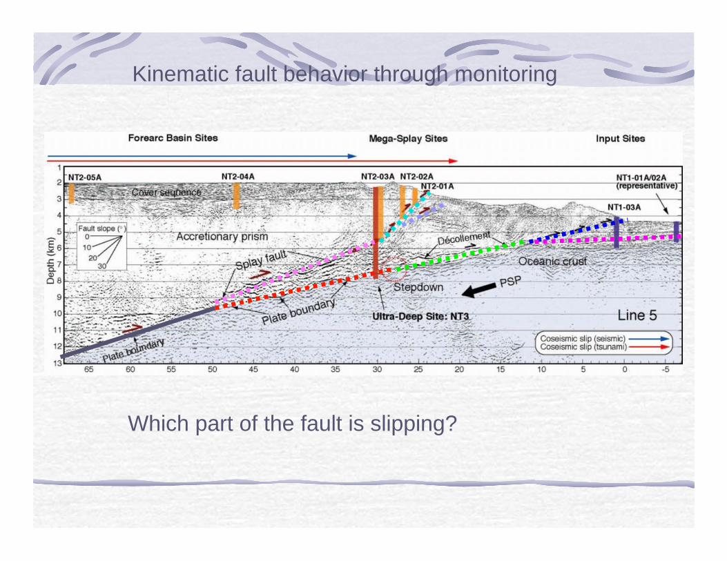
Which part of the fault is slipping?
Kinematic fault behavior through monitoring

Which part of the fault is slipping?
Kinematic fault behavior through monitoring
No Slip≠Locked (Kelin Wang; Hori)Asperity = Locked region

CDEX Technology Road Map
CDEX, JAMSTECNori KYO

2006.8.7-10.31@Off Shimokita•Casing run, Cementing, BOP/Riser deploy
•EDS (Emergency Disconnect System)
•Coring (beyond 2,111mbsf)
•RMS, Riser/Tensioner dynamic perfomance
•Cuttings process
•Interface of sub contractor instruments
•HSE-MS
•Logistics using helicopter/supply boat between on/off shore
•Laboratory process
SIT / Training Cruise

Off Shimokita Site
60km from Hachinohe 142°12.0328’ E 41°10.5983’ N Water Depth 1,183m
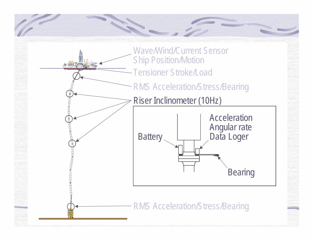
Measurement Riser MotionWave/Wind/Current SensorShip Position/MotionTensioner Stroke/Load
RMS Acceleration/Stress/Bearing
Riser Inclinometer (10Hz)
RMS Acceleration/Stress/Bearing
Battery
Bearing
AccelerationAngular rateData Loger
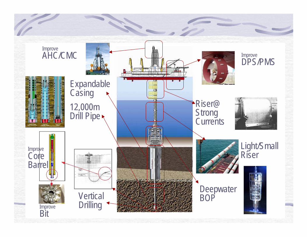
Riser / Drilling TechnologiesExpandableCasing
12,000mDrill Pipe
VerticalDrilling
Riser@StrongCurrents
Light/SmallRiser
DeepwaterBOP
Improve
CoreBarrel
Improve
Bit
Improve
AHC/CMC Improve
DPS/PMS

Deep Biosphere StudyOn boardCultivation
CoreCoated with Gel
In-situMeasurement
MediumTransfer
PressureRetainingValve
In-situSensor
RetainingPressure/Temperature
Methane Hydrate
Deep Biosphere
New Frontier

次世代の目標点
地震断層に直接掘削孔を掘り、地震・地殻歪変化(等)をモニタリングし、海底ケーブル等によりデータを陸上にリアルタイム伝送する。
技術開発の成果からどのような効果が期待されるか?
地震の発生過程を理解するための基礎データを得る
大地震発生時のリアルタイム警報に資する
200250
地震・地殻歪センサー
地震断層
孔内データのリアルタイム伝送 東南海地震発生帯海底断面図
Long Term Monitoring

Riser / Drilling Technologies
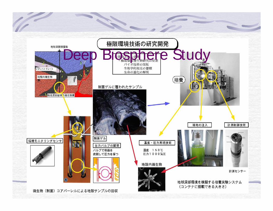
Deep Biosphere Study

Deep Biosphere Study

APPENDIX 7

Calendar year 2003 2004 2005 2006 2007 2008 2009 2010 2011 2012 2013
JFY H15 H16 H17 H18 H19 H20 H21 H22 H23 H24 H25
CDEX Efforts
Long Term Monitoring
Highly ranked proposals
NanTroSEIZE Pahse 3 (6 km Drilling)
CHIKYU Shake down Bengal
CHIKYU International Operation CRISPNanTRo Phase 1 Phase 2 Deep Bioshere
3.5 km Borehole 21st Century Moho
SIT
FS Design, Fabrication Implementation
Deep water, deep drilling development
Drilling under strong current Coring, drilling in fault zone

APPENDIX 8

United States Implementing Organization (USIO)United States Implementing Organization (USIO)Report to EDPReport to EDP
• SODV Status• WBS• Highlights• Issues• Schedule

SODV WBS and BudgetSODV WBS and Budget
WBS 1.0Scientific Ocean Drilling Vessel
Conversion
$104,000,000
WBS 1.1SODV Program
Management
$8,386,876
WBS 1.2 Science System
$16,985,139
WBS 1.3 SODV Conversion
$78,388,385
WBS 1.4 Health, Safety &
Environment
$239,600
WBS 1.5 Pre-Operational
Evaluation
$0
JOI Contingency $5.0 MNSF Management Reserve $6.0 M

USIOSODVSODV HighlightsHighlights
•• Completed negotiations for SODV and loggingCompleted negotiations for SODV and loggingsubcontractssubcontracts
•• Engineering design continuesEngineering design continues–– Integration of mechanical elements into designIntegration of mechanical elements into design–– Final design package planned Aug 06Final design package planned Aug 06–– Preliminary stability analysis completedPreliminary stability analysis completed–– Initial dialogue established with shipyardsInitial dialogue established with shipyards
Selection anticipated Autumn 06Selection anticipated Autumn 06
•• Science instrumentationScience instrumentation–– Work packages prioritized based on STP minimum,Work packages prioritized based on STP minimum,
standard, supplemental measurement capabilitiesstandard, supplemental measurement capabilities–– Authorizations issued for initial group of work packagesAuthorizations issued for initial group of work packages–– Remaining packages will be considered once shipyardRemaining packages will be considered once shipyard
prices are knownprices are known

USIOSODV HighlightsSODV Highlights
•• Established initial project baselineEstablished initial project baseline–– Reexamine baseline once shipyard costs are finalizedReexamine baseline once shipyard costs are finalized
•• NSF management review completedNSF management review completed–– Program status, requirements, WBS, budget, schedule &Program status, requirements, WBS, budget, schedule &
shipyard selectionshipyard selection–– Next review targeted for Autumn 2006Next review targeted for Autumn 2006
•• Continued development of EISContinued development of EIS–– Exhaust emissions, acoustic measurements, seafloor cuttingsExhaust emissions, acoustic measurements, seafloor cuttings
•• Issues still under considerationIssues still under consideration–– VisualizationVisualization–– Acquisition of larger diameter pipe for loggingAcquisition of larger diameter pipe for logging–– Core recovery/quality & heave compensationCore recovery/quality & heave compensation

USIOSeafloor VisualizationSeafloor Visualization
•• ObjectivesObjectives– Re-entries– Seafloor surveys– Borehole observation – Safety– Specialized equipment observation– Geological and biological observation– Reliability and improved visualization

USIOSeafloor VisualizationSeafloor Visualization
•• Current CapabilityCurrent Capability–– Vibration Isolated Television (VIT) frameVibration Isolated Television (VIT) frame–– Hydraulic winch with 22,000Hydraulic winch with 22,000’’ cable (coax) cable (coax)–– Sonar headSonar head–– Remote video camera B/W fixed focus, noRemote video camera B/W fixed focus, no
pan/tiltpan/tilt–– Every situation involving a rotating stringEvery situation involving a rotating string
involves risk to the umbilicalinvolves risk to the umbilical
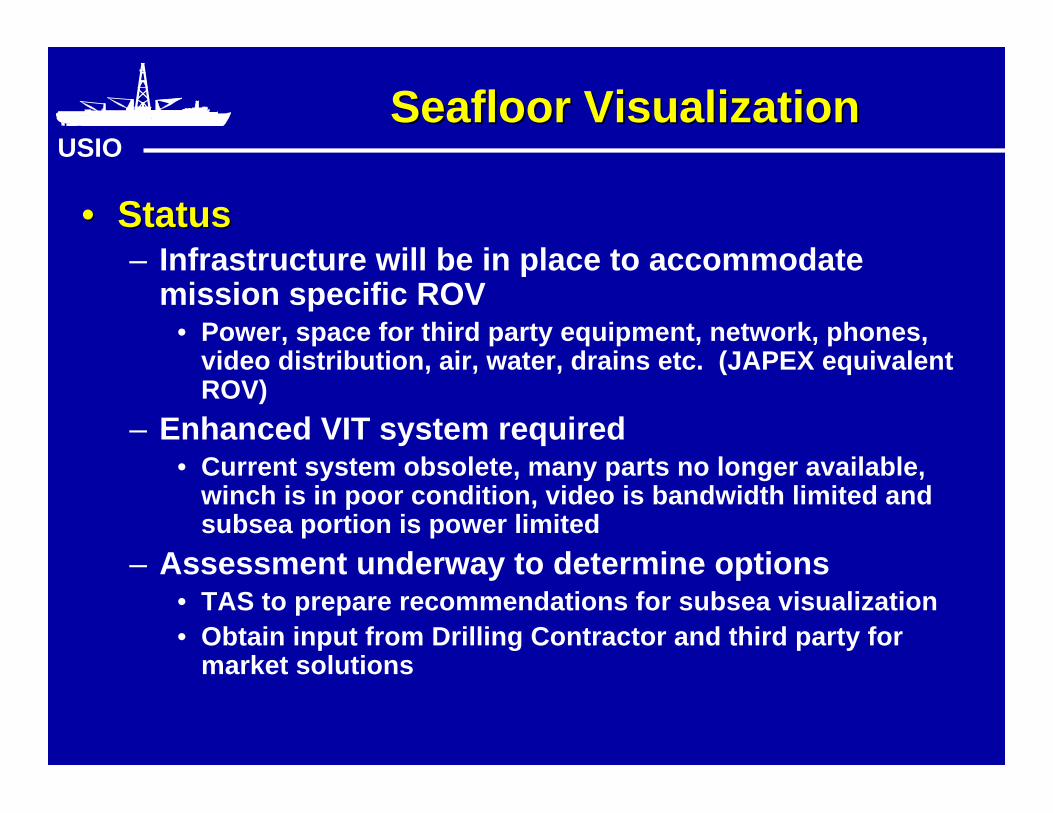
USIOSeafloor VisualizationSeafloor Visualization
•• StatusStatus– Infrastructure will be in place to accommodate
mission specific ROV• Power, space for third party equipment, network, phones,
video distribution, air, water, drains etc. (JAPEX equivalentROV)
– Enhanced VIT system required• Current system obsolete, many parts no longer available,
winch is in poor condition, video is bandwidth limited andsubsea portion is power limited
– Assessment underway to determine options• TAS to prepare recommendations for subsea visualization• Obtain input from Drilling Contractor and third party for
market solutions

USIOLarge Drill Pipe ConduitLarge Drill Pipe Conduit
•• ObjectivesObjectives– Enhancements to the logging capability using larger diameter
tools– Does not include larger diameter cores
• Improve log resolution using state-of-the-art technology– Improvements in minimum measurement capabilities:
• Increased measurement resolution (e.g. wide-swath images)• Large-hole clamping capacity (e.g., VSP)• Less downhole logging time (e.g., shorter tool strings, faster
sampling)
• Allows new downhole measurements– NMR (nuclear magnetic resonance)– Geochemical spectroscopy– In situ bulk permeability & fluid sampling
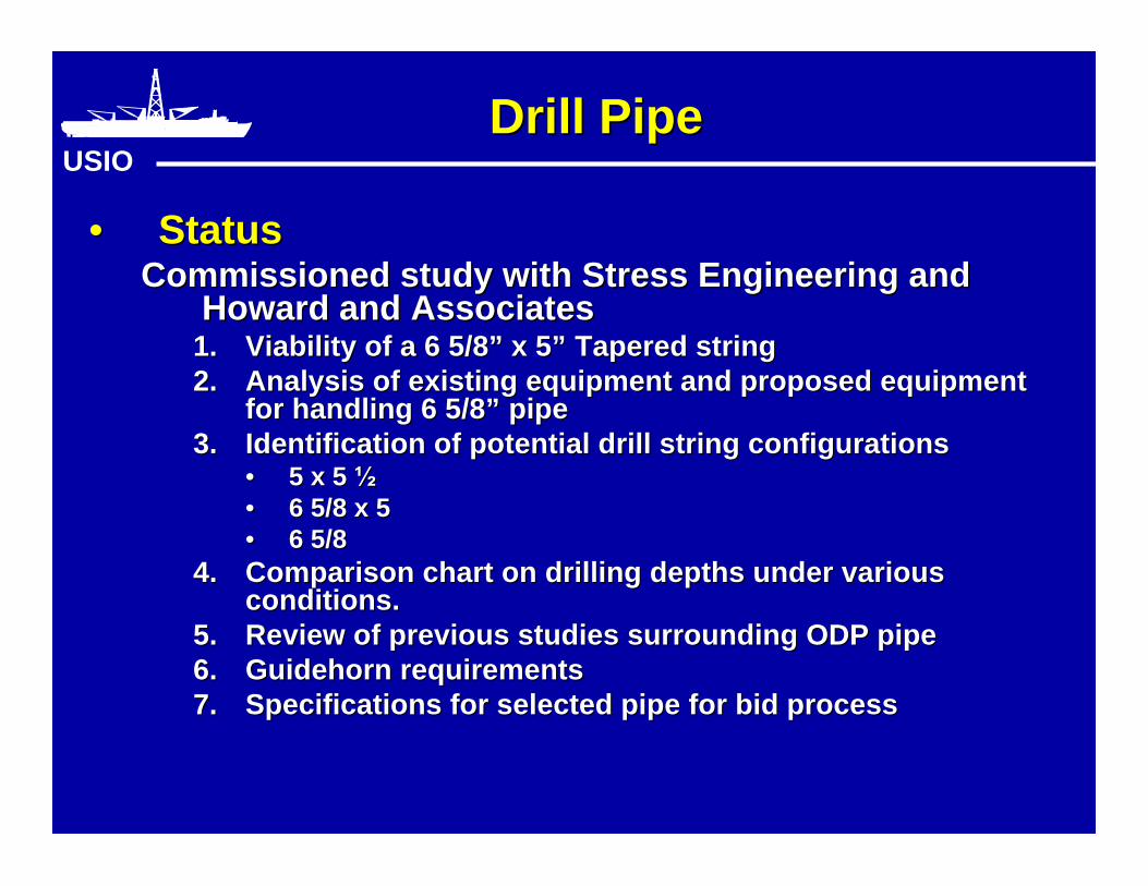
USIODrill PipeDrill Pipe
•• StatusStatusCommissioned study with Stress Engineering andCommissioned study with Stress Engineering and
Howard and AssociatesHoward and Associates1.1. Viability of a 6 5/8Viability of a 6 5/8”” x 5 x 5”” Tapered string Tapered string2.2. Analysis of existing equipment and proposed equipmentAnalysis of existing equipment and proposed equipment
for handling 6 5/8for handling 6 5/8”” pipe pipe3.3. Identification of potential drill string configurationsIdentification of potential drill string configurations
•• 5 x 5 ½5 x 5 ½•• 6 5/8 x 56 5/8 x 5•• 6 5/86 5/8
4.4. Comparison chart on drilling depths under variousComparison chart on drilling depths under variousconditions.conditions.
5.5. Review of previous studies surrounding ODP pipeReview of previous studies surrounding ODP pipe6.6. GuidehornGuidehorn requirements requirements7.7. Specifications for selected pipe for bid processSpecifications for selected pipe for bid process

USIODrill PipeDrill Pipe
•• StatusStatus–– Converted additional 5Converted additional 5”” pipe pipe rackerracker to handle 6 5/8 to handle 6 5/8””
pipepipe–– Preparing specifications on drill pipePreparing specifications on drill pipe
•• Purchase 2800 m of 5Purchase 2800 m of 5”” Drill Pipe Drill Pipe•• Split order of 5 ½Split order of 5 ½”” Drill Pipe Drill Pipe
•• Purchase 1300 m of 5 ½Purchase 1300 m of 5 ½”” Drill Pipe Drill Pipe
–– Decision of 6 5/8 pendingDecision of 6 5/8 pending Consultant assessments, shipyard bids, priorityConsultant assessments, shipyard bids, priority
•• Purchase eitherPurchase either•• 1300 m of 5 ½1300 m of 5 ½”” pipe pipe•• 4000 m of 6 5/84000 m of 6 5/8”” pipe pipe

USIOHeave CompensationHeave Compensation
•• ObjectivesObjectives• Improved core recovery• Improved core quality•• Land equipment at sea floor safely andLand equipment at sea floor safely and
efficientlyefficiently

USIOHeave CompensationHeave Compensation
•• CapabilityCapability–– System performance varies with respect to theSystem performance varies with respect to the
system configuration and vessel characteristicssystem configuration and vessel characteristics–– Depending on above there can be 10x variance inDepending on above there can be 10x variance in
performance.performance.–– Current limitationsCurrent limitations
•• AHC or passive modeAHC or passive mode•• Little ability to adjust or Little ability to adjust or ““tunetune”” the system to reduce cross- the system to reduce cross-
coupling affects while operatingcoupling affects while operating•• Present system arrangement contributes to significant otherPresent system arrangement contributes to significant other
inefficiencies (PHC)inefficiencies (PHC)•• System controls motion at the top and this does notSystem controls motion at the top and this does not
necessarily translate to control weight at the bitnecessarily translate to control weight at the bit

USIOHeave CompensationHeave Compensation
•• StatusStatus–– Internal assessment of specific JR situationInternal assessment of specific JR situation
•• Identify specific parameters affecting AHC and PHCIdentify specific parameters affecting AHC and PHCperformanceperformance
•• Seals, drill string dynamics, fluid flow, arrangement constraints,Seals, drill string dynamics, fluid flow, arrangement constraints,phase relationshipphase relationship
•• Determine accuracy and validity of initial designDetermine accuracy and validity of initial design–– Improve PHC performanceImprove PHC performance–– Review AHC optionsReview AHC options–– Determine potential strategies for longer term WOBDetermine potential strategies for longer term WOB
controlcontrol i.e. Drill string stabilization, RIG, bumper subs, seafloori.e. Drill string stabilization, RIG, bumper subs, seafloor
framesframes
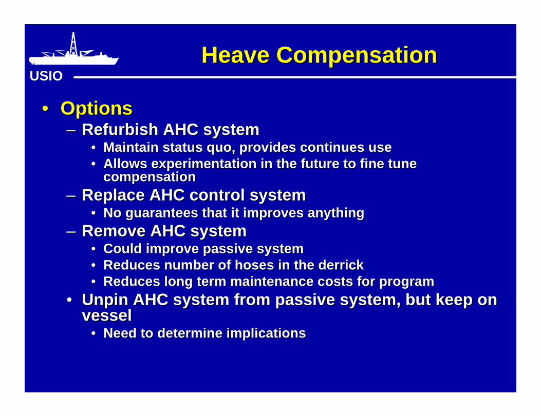
USIOHeave CompensationHeave Compensation
•• OptionsOptions–– Refurbish AHC systemRefurbish AHC system
•• Maintain status quo, provides continues useMaintain status quo, provides continues use•• Allows experimentation in the future to fine tuneAllows experimentation in the future to fine tune
compensationcompensation–– Replace AHC control systemReplace AHC control system
•• No guarantees that it improves anythingNo guarantees that it improves anything–– Remove AHC systemRemove AHC system
•• Could improve passive systemCould improve passive system•• Reduces number of hoses in the derrickReduces number of hoses in the derrick•• Reduces long term maintenance costs for programReduces long term maintenance costs for program
•• Unpin AHC system from passive system, but keep onUnpin AHC system from passive system, but keep onvesselvessel
•• Need to determine implicationsNeed to determine implications

USIOSODV Conversion ScheduleSODV Conversion Schedule
Engineering Design PhaseEngineering Design Phase Feb 06 - Sept 06Feb 06 - Sept 06 Shipyard SolicitationShipyard Solicitation Apr 06 - May 06Apr 06 - May 06 Review Shipyard ProposalsReview Shipyard Proposals June 06 - Aug 06June 06 - Aug 06 Ship Arrives, Tanks CleanedShip Arrives, Tanks Cleaned Nov 06 - Nov 06Nov 06 - Nov 06 Ship in shipyardShip in shipyard Nov 06 - Sept 07Nov 06 - Sept 07 Dock Trials, Inclining, CompletionDock Trials, Inclining, Completion Oct 07 - Oct 07Oct 07 - Oct 07

USIOSODV Conversion ProjectSODV Conversion Project
Apr May Jun Jul Aug Sep
RFI Preliminary Detailed Final43 8 2/3 1/2
PreliminaryEngPkg
DetailEngPkg
FinalEngPkg
InterestCapacityViability
SY Std Practice Spec’sBudget Cost
Preliminary ScheduleFinalize options
Project Accepted Spec’sHard Cost
Fixed Schedule
ReviewDetailedProposal
against finalEng Pkg
Tech/CommContract
negotiations
SYContract
1
SY Kick-off Mtgs
Preliminary Proposals
On-Site Follow-up Mtgs
SY evaluation/Selection
Preliminary Shipyard Selection ExercisePreliminary Shipyard Selection Exercise
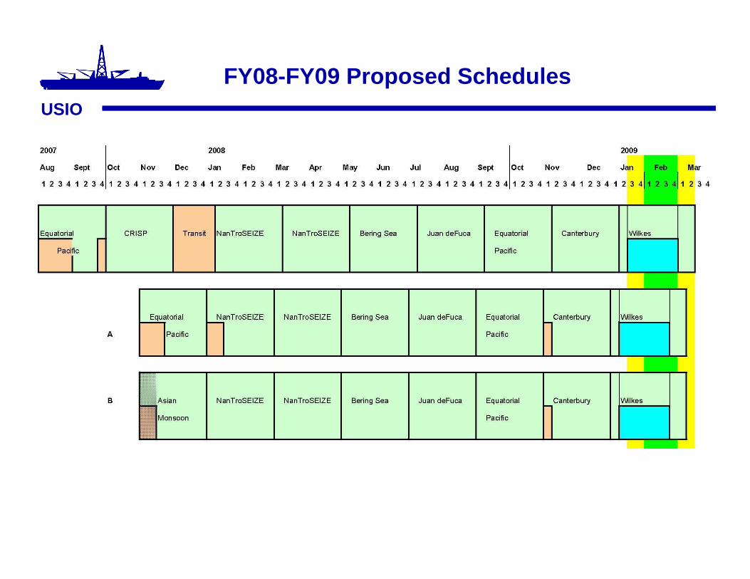
FY08-FY09 Proposed SchedulesUSIO

USIOSODV After ConversionSODV After Conversion
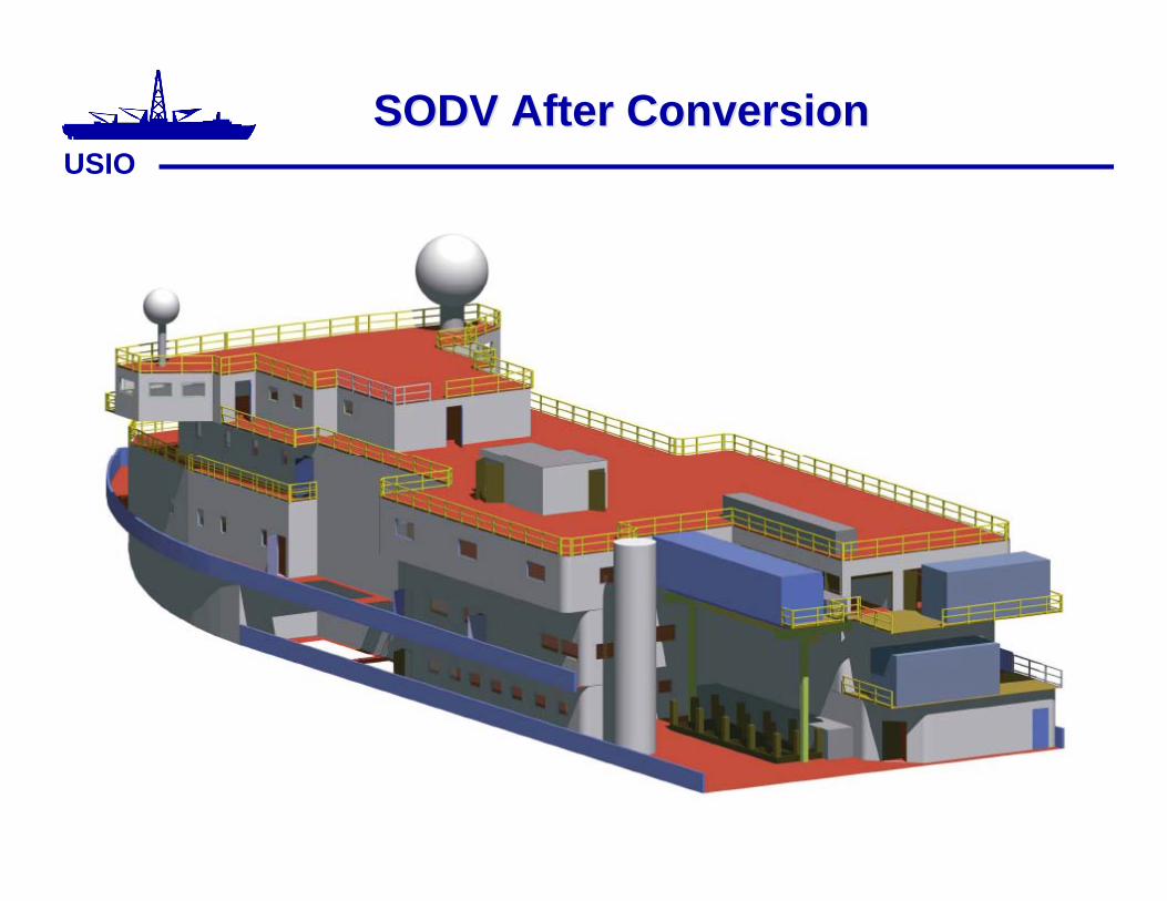
USIOSODV After ConversionSODV After Conversion

USIOSODV Design AdjustmentsSODV Design Adjustments
•• Minimal adjustments to design / layout toMinimal adjustments to design / layout toaccommodate mechanical and structuralaccommodate mechanical and structuralrequirementsrequirements
–– Chemistry, microbiology, and paleontology areaChemistry, microbiology, and paleontology arearearrangedrearranged
–– Core splitting room slightly relocated starboardCore splitting room slightly relocated starboard(still off center portside)(still off center portside)
–– Storage areas rearranged and increased spaceStorage areas rearranged and increased space

United States Implementing Organization (USIO)United States Implementing Organization (USIO)Report to EDPReport to EDP
• Operational Activities

APPENDIX 9

Coring Tools Availablefor Mission Specific Platforms
Iain PheasantECORD Science Operator
EDP
June 27-29 Windischeschenbach

‘Api’ Coring Tools• Suite used by JOI Alliance• Suite used by CEDEX• Suite used by BGS/ACEX• Suite used by Russia for Lake Baikal• Possibly suite modified by DOSECC
All use a specialised Bottom Hole Assemblyto allow wireline coring techniques inside a
Modified (larger ID) API Oilfield Pipe
Last three suites have common BHA and canaccept geotechnical sampling tools

’Mining’ Coring Tools• Boart Longyear• Cralieus• Various Australian and South Africian varieties All are wireline operated with mining drillstring which needs
lateral support if used offshore• Generally for Hard rock but with geotechnical variations of
push and percussion sampling• A large variety of core diameters and ‘nested’ sizes which
allows the first string to operate as the casing for the secondstring
• Classed in the industry and by BGS/ESO as ‘piggy backcoring’ due to mode of operation offshore

PiggybackCoring

DOSECC Coring
• Hybrid of API and Mining providing a wirelinecoring system which is less robust that API butwhich is now being used with API pipe inoffshore work.
• This system also has a common BHA and a rangeof geotechnical type tools
• I expect, but have not explored the possibilities,that Russia and China have a large variety ofcoring options also.
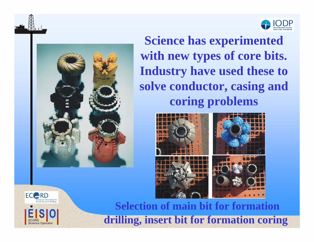
Selection of main bit for formationdrilling, insert bit for formation coring
Science has experimentedwith new types of core bits.Industry have used these tosolve conductor, casing and
coring problems

Remotely operated Seabed Coring ToolsPROD – Withdrawn from science, active in industry
BGS 5m Rockdrill/Vibrocorer – Active in science and Industry
BGS Oriented Core Drill – Active in Science
MEBO – commencing operations this summer
RD 2 – commencing operations this autumn
All can be used toprovide a real extent
to prepare for andaugment deep holes

New Deeper PenetrationRemote Drills
PROD MeBoRD2

Issues Surrounding widevariety of Coring Systems
available for ESO (and others)• MSP’s can specify the best coring system for the
project as they are not linked in to any onesystem and therefore do not have to make ‘onesize fit all’ (it is possible that the third MSP willhave yet another coring system to the twoalready used)• However core diameters are an issue for the
ongoing laboratory work curation and storageso there are restrictions which can bedetrimental to the core recovery and qualityimposed on the selection of the equipment bythe subsequent processes
Comment
• The list of ‘off the shelf tools’ is vast. Manycountries in the world conduct drilling andcoring, we in the west have just not looked into itproperly and have relied on the oil industry andwell known mining suppliers for our informationand technology.
• Similarly most wireline drilling systems utilise aBottom Hole Assembly (BHA) which allows alltools to be operated within it. Some even havewireline retrievable and exchangeable core bits

New Jersey Shallow ShelfGreat Barrier Reef?
New England Hydrogeology?
Your Scientific Requirement and IODP approval to use it determines the
Equipment !
ESO look forward to helping IODPscientists achieve their objectivesthrough future MSP drilling with avariety of single BHA, integrated
coring systems

APPENDIX 10

SODV -- Update of PACIssues for EDP
David ChristieUniversity of Alaska, Fairbanks
For the Program Advisory Committee

Part 2: EDP issues
oDrill String Configuration
oSubsea Visualization
oHeave Compensation

Drill String Options and Recommendations PART 2 - OPTIONS BEING IMPLEMENTED
II. IMPLEMENTED:
Option 3: Acquire a tapered 6-5/8" OD °— 5" OD string• 6-5/8" OD portion allows for for logging with large diameter tools to ~ 3000 meters water depth• Extends the depth-to-core capability to about 7,200meters
--3,000 meters of 6-5/8" pipe--4,200 meters 5" pipe
*** Does not require development/acquisition of new larger drillcollar string (6-5/8" OD pipe will not enter the hole during coringoperations.

Drill String Options and Recommendations PART 1 - OPTIONS NOT IMPLEMENTED
• Option 1: Utilize one or two pipe rackers for 6-5/8" OD drill pipe to be used as alogging conveyance riser only
• Reduces the depth-to-corecapability of the rig (by the amount of 6-5/8"rackerspace)
• Utilizing one racker’s capacity for 6-5/8 conveyance string results in a depth-to-log capability of 2,800 meters and a depth-to-corecapability of 6,450 meters.
• Option 2: Utilize a new string design that allows the use of the same pipe forboth coring and logging on every hole.
• キ Full string of 6-5/8" OD S-140 drill pipe in the range of 6,600meters pending final results of the drill pipe design study.
• キ Higher cost
• Option 4: Develop an alternative logging tool conveyance system• キ Uses existing 5-1/2" OD ° to 5" OD drill pipe• キ Adds ~ 100 meter 6-5/8"OD carrier shroud at the bottom of the
string to allow delivery of large diameter tools

Part 1: Quick overview
Part 2: EDP issues
oDrill String Configuration
oSubsea Visualization
oHeave Compensation

Seafloor Visualization
Design Team Recommendation
1. Refurbish or replace the winch for 6000 m capability.
2. Purchase two 8000 m steel strength-member single-
mode fiber optic cables (requires new telemetry). The
working depth of the cable has to be 4500 m with a safety
factor of 4.
3. Replace old equipment (e.g., sonar, camera, and
lights)

Seafloor Visualization - 2
Statement of Work (SOW) has been prepared (andsent to ODL for implementation -??)
New System FeaturesNew color and/or BW cameras with pan/tiltNew sonarPorts for additional instrumentsGyro (working)Device for maintaining/controlling headingNew frame and winch systemsNew onboard interface

Part 1: Quick overview
Part 2: EDP issues
oDrill String Configuration
oSubsea Visualization
oHeave CompensationoScience Drivers
oSODV view

Heave CompensationI. Perceived Science Issues
SODV
**Note: More core is not always the sole objective.In some situations, faster penetration, even at the expense of recovery may bedesirableNote 2: APC was not mentioned in the PAC document
****

Heave CompensationI. SODV Issues
(From Frank Williford - USIO)
Integrated Ocean Drilling ProgramU.S. Implementing Organization
16 May 2006
SODV

Our Original Objectives
• Improve core quality and recovery• Land modest weights at sea floor safely
and efficiently
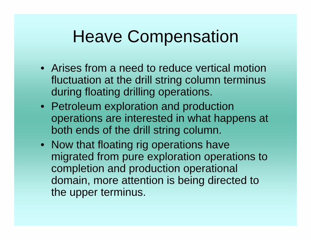
Heave Compensation
• Arises from a need to reduce vertical motionfluctuation at the drill string column terminusduring floating drilling operations.
• Petroleum exploration and productionoperations are interested in what happens atboth ends of the drill string column.
• Now that floating rig operations havemigrated from pure exploration operations tocompletion and production operationaldomain, more attention is being directed tothe upper terminus.
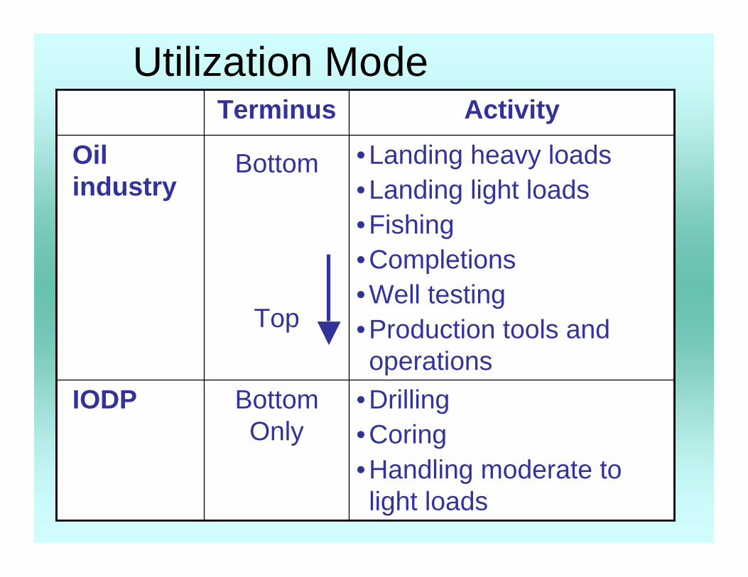
Utilization Mode
•Drilling•Coring•Handling moderate tolight loads
BottomOnly
IODP
•Landing heavy loads•Landing light loads•Fishing•Completions•Well testing•Production tools andoperations
Bottom
Top
Oilindustry
ActivityTerminus
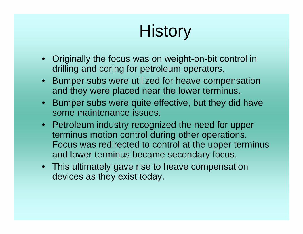
History• Originally the focus was on weight-on-bit control in
drilling and coring for petroleum operators.• Bumper subs were utilized for heave compensation
and they were placed near the lower terminus.• Bumper subs were quite effective, but they did have
some maintenance issues.• Petroleum industry recognized the need for upper
terminus motion control during other operations.Focus was redirected to control at the upper terminusand lower terminus became secondary focus.
• This ultimately gave rise to heave compensationdevices as they exist today.

Observations / Considerations
• Heave compensation is not perfect in practice. Thereis significant system performance variance withrespect to the system arrangement and the type ofvessel on which it is deployed.
• Depending on the vessel type and the systemarrangement there can be as much as a ten-foldvariance in system performance.
• If focus is on the upper terminus this provides theopportunity to place motion sensors near the point ofapplication and focus, thus avoiding many potentialsystem variables.

Utilization Mode-Load Fluctuation
± 6%± 8%± 10%Drill ship (JR type)
± 2%± 4%± 5%Semi-submersible
± 1%± 2%± 3%Large semi-submersible
± 7%
Inline
± 4%± 5%Large drillship
Draw works(active)
Crownmounted
System ArrangementVessel Type
Notes:• Vessel motions forcing this activity fluctuate for a given sea
state with respect to a vessel type.• Linked Factors: Water depth, drill column restraint, vessel
RAO or heave function

Typical RAO Comparison
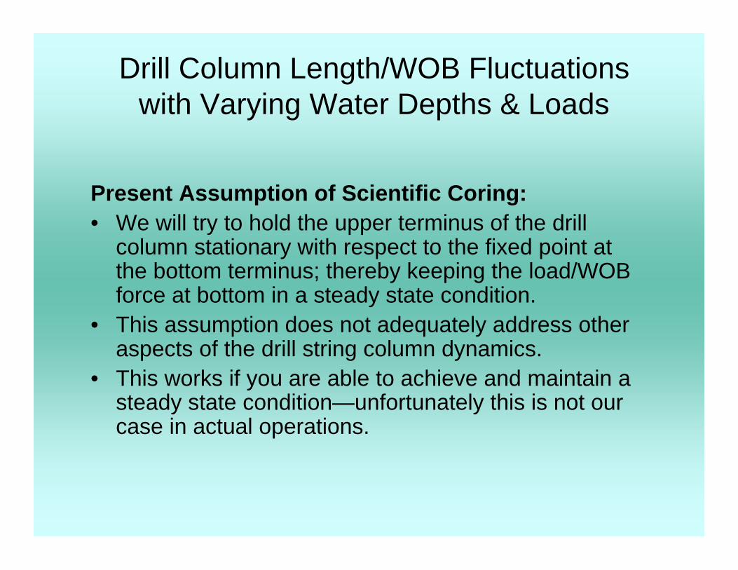
Drill Column Length/WOB Fluctuationswith Varying Water Depths & Loads
Present Assumption of Scientific Coring:• We will try to hold the upper terminus of the drill
column stationary with respect to the fixed point atthe bottom terminus; thereby keeping the load/WOBforce at bottom in a steady state condition.
• This assumption does not adequately address otheraspects of the drill string column dynamics.
• This works if you are able to achieve and maintain asteady state condition—unfortunately this is not ourcase in actual operations.

Drill Column Length/WOB Fluctuations
15.0″7.5″0.75″15,000
5.0″2.5″0.25″5,0001.0″0.5″0.05″1,000
0.50″
1K
10.0″5.0″10,000
20K10K
Δ WOB (kips)Columnlength
(ft)
Fluctuations with varying water depths and loads:What really happens…

How are IODP Operations Differentfrom the Petroleum Industry?
• Extreme water depth• Unconstrained drill column vibration and
flexure modes over most of the (riserless)length
• Flexure and drag forces from ocean currentsand ship excursions
• All of these factors cross couple on certainoccasions to preclude maintaining a steadystate condition

System Factors Affecting thePresent AHC System
• Locked-in to a distinct and limited array ofoperating modes (system limitation)
• Little ability to adjust or “tune” the system toreduce cross-coupling affects while operating
• Present system arrangement contributes tosignificant other inefficiencies

Present Situation ~ WayForward - Ongoing
• Commission a study of our actual situation:To identify specific parameters affecting theperformance of both our AHC and PHC systems inorder to refine the accuracy and validity of initialdesign assumptions and parameters, and adjustexpectations for the system.
• Utilize available technology and techniques (such asMSE*), to improve PHC performance.
• Revisit actual operational activity and needs versusdesired results and investigate alternate ways toachieve those results.
• * MSE - Mechanical Specific Energy

Our Original Objectives
• Improve core quality and recovery• Land modest weights at sea floor safely
and efficiently

Conclusion - Ends Franks Presentation
• Motion compensation of a column in a verticalorientation is not the end-all solution to reach ourobjectives.
• AHC is a product looking for a problem it can solveand has enjoyed some success when deployed onvessels with greater mass, low water plane area,modest water depths, and restrained drill stringcolumn.
• Today, most petroleum operators focus on PHC asthe most cost efficient method to meet theirrequirements. Maintenance costs are significantlyreduced and up-time is improved.
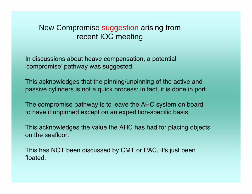
New Compromise suggestion arising fromrecent IOC meeting
In discussions about heave compensation, a potential'compromise' pathway was suggested.
This acknowledges that the pinning/unpinning of the active andpassive cylinders is not a quick process; in fact, it is done in port.
The compromise pathway is to leave the AHC system on board,to have it unpinned except on an expedition-specific basis.
This acknowledges the value the AHC has had for placing objectson the seafloor.
This has NOT been discussed by CMT or PAC, it's just beenfloated.


APPENDIX 11

Long Term Borehole Monitoring SystemCurrent Status of FY06 Feasibility Study
Plan for FY07~
Prepared for
Engineering Development Panel MeetingJune 27-29, 2006 Windischeschenbach, Germany
June 27-29, 2006

1. Scientific RequirementWhat are the essential /practical tasks?-
NanTroSEIZE case-
• Drilling through the Updip limit of asperity, not inthe center.– Crustal deformation throughout the hanging wall
to the fault zone– How the strain caused by the backstop and
subducting plate affect the fault plane strain?– Any slip across the fault? - monitoring– Is it LOCKED? Is it weak? -rock mechanics exp. etc.
Correlation with asperity inferred from 3D seismics
– Monitoring of seismogenic process

Scientific needs
NanTroSEIZE

Which part of the fault is slipping?
Kinematic fault behavior through monitoring

Summary of desired specifications of sensors ( Shinohara et al., (2003) except for osmo sampling)
• Seismicity‒ Noise floor:10-7 m/s2 at 10 Hz
‒ Maximum acceleration: 100 g
‒ Frequency band: From 0.5-1000 Hz
Strain and Tilt
Sensitivity: ̃10-12 for volumetric strain is best sensitivity , ̃1 nrad for tilt
Size: 3" in diameter and 120 cm in length.
Function: Leveling mechanism
Sampling: 1 sec
Temperature
Precision: 1 mK (relative), 100 mK (detection of pore fluid flow). 1 K (absolute)Sampling: About 1 minute
Pressure
Sensitivity: ̃104 Pa (1 day, 1/2 day), and detectable 10 Pa (100 sec) Absoluteaccuracy: 1 MPa Sampling: About 1 minute
• Electromagnetic observations‒ Sensitivity: 0.01 mV (for electric field) 0.001 nT (for magnetic field) Sampling: About 1minute
Osmo sampling
Osmo samplers built for a 13 month deployments displacing about 16 mL/h.

Technical Requirements-Constraint-
Another constraint is a physical dimension. A deep riser-hole drilling requiresmany layers of casing. Casing strings are basically hung from the casinghanger at the wellhead. The last (deepest) casing size is normally 9 5/8”. A7” liner is hung from the bottom of the 9 5/8” casing. If 7” liner is used tohold downhole sensors and telemetry assembly, the allowable space fortelemetry and sensors is very limited (Figure 3). This is a large differencefrom CORK system that has a 10 3/4” single casing, and more space isallowed for cable and sensors (Figure 4). In addition, all the electric andhydraulic lines need to be output through pressure-controlled penetrators atthe tubing hunger in riser hole (Figure 5). The number of penetrators oncommercial Christmas tree (a pressure control device upon wellhead) is sixto eight. This is a major difference from on-land boreholes that haveessentially no limitation for the number of penetrators.

Figure 2: Survival functions for two temperature ranges of PQG installations made in293 wells from Mar 21, 1994, to Apr 12, 2000.

Technical Requirements-Relaibility-
The highest priority thing is long- term reliability, rarher than capability.
The system is used for many years under high temperature condition.
In the case of the NanTroSEIZE observatories, bottom temperatures of theboreholes are estimated as 125 ℃ for 3.5 km hole, and 180 ℃ for 6 km hole.
From the examples in oil fields, five-year survival rate of the pressuresensor installed at 100-155 ℃ is only 55% (Figure 2).
There are two key aspects for improvement of system reliability.
1. long mean-time-between-failure (MTBF) of each element, and
2. fault tolerant configuration of the system. Development of theinstruments/elements of higher reliability requires many years of engineeringand field practice as well as huge amount of budget. Therefore, the practicalbest way is to apply field proven technologies in oil fields as much aspossible.

Tool Diameter1 11/16 Sensor + Electronics
2 7/8 Tubing
7 Casing
10mm
22mm
43mm
148mm
73mm
We recommend tool OD to be standard 1 11/16” rated to 20,000 psi
Max 33mm OD for• Coils• Capacitances• PCB• Sensors
Figure 3: Available space in 7” casing.

Figure 4: ACORK Borehole Observatory. (http://www-odp.tamu.edu/publications/tnotes/tn31/pdf/acork.pdf)
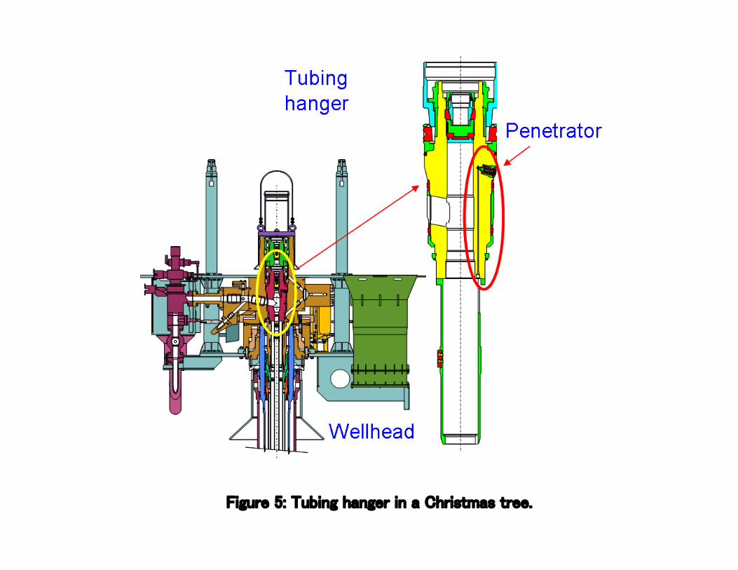
Figure 5: Tubing hanger in a Christmas tree.
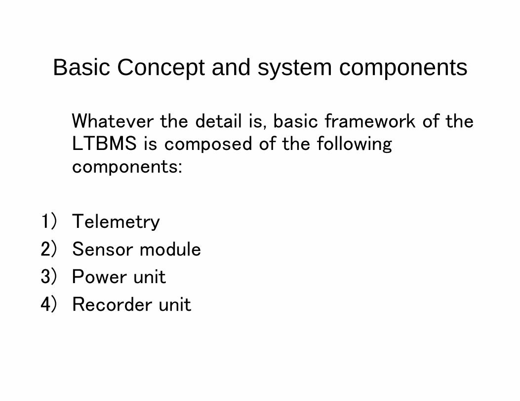
Basic Concept and system components
Whatever the detail is, basic framework of theLTBMS is composed of the followingcomponents:
1) Telemetry
2) Sensor module
3) Power unit
4) Recorder unit

Basic Concept and system components -Functionalities-
According to the scientific and technical requirements mentioned above,LTBMS is desired to have the following functionalities:
(1) Multi-level data acquisition including seismic, geodetic (tilt, strain), pressureand temperature, electromagnetic, and osmo sampling with requiredprecision, accuracy and data rate.
(2) Digital telemetry with sufficient data rate.
(3) Remote controllability by commands.
(4) Long-term reliability under high temperature condition.
(5) Physical size: small enough to be installed to 7” liner.
(6) Low power consumption.
(7) Data harvest by ROV.
• (6) and (7) can be ignored in online observatory.

Controller
Power
Telemetry A
SubseaTelemetry System
Downholemodule
Telemetry B
Telemetry
Power
¼” Standard Completion Cable
Battery
Controller Sensors
Hard Disk
Pro
toco
l, In
terfa
ce, &
Pow
er S
peci
ficat
ions
SubseaSystem
Protocol, Interface, &Power Specifications
Protocol, Interface, &Power Specifications
Sensor Module
Figure 6: Basic concept of system design.

Basic Concept and system components -System Components-
Telemetry
Sensor and downhole modules
Seabed module
Recording unit
Power unit
Communication interface
Timing accuracy
Data management

Up-coming work : High Level Design Document
In High Level Design (HLD) document which will be submitted after reviewof the System Architecture document and will be completed as part ofthe feasibility study, more detailed technical specifications will beprovided. Major subjects are as follows.
・ System topology Fault-redundant and low power telemetry topology.
・ Specifications of telemetry Data rate, frequency allocation, synchronization,frame design, error rate....etc.
・ Power consumption estimation and power supply Power consumption ofsensors and cable. Battery specification assuming one year-longobservation.
・ Sensor interface Design interface assuming possible sensors connected tothe system.
・ Data storage specification Design of subsea recorder unit as well as interfacespecification to ROV, transponder, and subsea cable.
・ Deployment and maintenance operatability Operationally feasible mechanicaland physical design.

Figure 7: Schematic drawing of the system including subsea anddownhole modules.

5. Technology development elements
(1) Downhole power consumption(2) Temperature rating(3) Downhole Telemetry System(4) Reliability(5) Sensor interface(6) Data compression(7) Data harvest(8) Wellhead(9) Redundancy

Inferred thermal structure (Preliminary result by Kelin Wang)
Heat flow across the Nankai Trough off Kumano
Updip limit of stick slip zone ?

(Drawing by A. Sakaguchi)
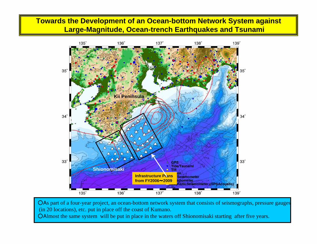
Towards the Development of an Ocean-bottom Network System againstLarge-Magnitude, Ocean-trench Earthquakes and Tsunami
Infrastructure Plans from FY2006~2009
Kii Peninsula
Shionomisaki
○As part of a four-year project, an ocean-bottom network system that consists of seismographs, pressure gauges (in 20 locations), etc. put in place off the coast of Kumano.○Almost the same system will be put in place in the waters off Shionomisaki starting after five years.

Development plan FY-07 Development Phase
Major milestones
Based on the the Feasibility Phase of the Long Term Monitoring System, which has beencarried out in 06FY, we propose to start Design and Fabrication Phase form 07 through 09,which will be followed by Implementation phase.The budget for Development Phase (07, 08and 09 FY) will be by SOC, and that for Implementation Phase will be by POC.
sFY 07Q1: Based on the FS, we start design, component procurement and softwaredevelopment.FY 07Q2: Finish design, continue component procurement and softwaredevelopment, and start part machining.FY 07Q3: Finish component procurement, continuesoftware development, and start fabrication.FY 07Q4: Continue software development andfinish fabrication.In FY08:Continue software development, start testing and debugging andlong term testing.In FY09:Continue long term testing and conduct field test.ImplementationPhase:Based on the products of the Development Phase, the Implementation will start fromFY2010. This phase will be, for example, for NanTroSEIZE.The real system will beimplemented and installed in FY2010 and FY2011, then the observation will start in FY2011.

Major Development Elements
(1) Downhole power consumptionCurrent Technology: 10 W per levelDevelopment element: reduce down to 2W (wish)
(2) Temperature ratingCurrent Technology: <80℃Development element: 125℃ (In NanTroSEIZE phase 2)
(3) Downhole telemetry systemCurrent Technology: co-axial, FODevelopment element: co-axial for high temperature
(4) ReliabilityCurrent Technology:repaired by handDevelopment element:Fault tolerance(1) Telemetry system and topography(2) Sensor interface(3) Data compression(4) Data harvest

Major Development Elements
(5) Telemetry system and topographyCurrent Technology: No available systemDevelopment element: Topography, Data format (high sampling rate+low sampling
rate), Cable length(6) Sensor interfaceCurrent Technology: Seismic only or pressure onlyDevelopment element:Multiple sensors(7) Data compressionCurrent Technology: WINDevelopment element:Modified WIN(8) Data harvestCurrent Technology: Dedicated single instrument or unit recoveryDevelopment element:Support various interfaces
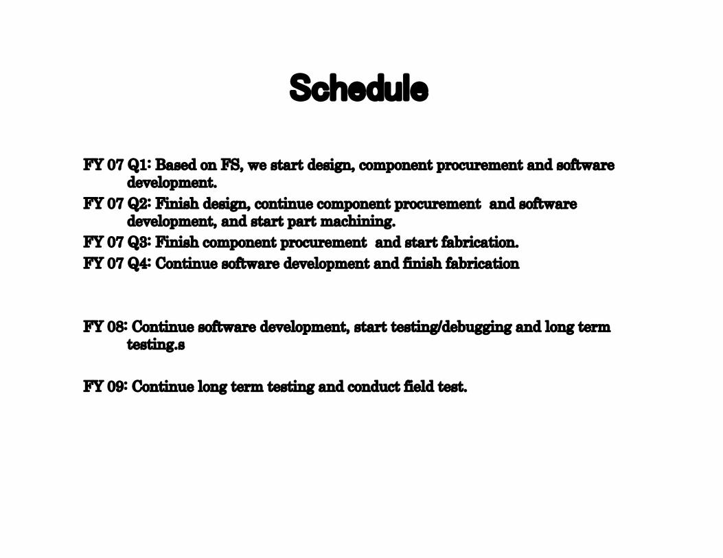
Schedule
FY 07 Q1: Based on FS, we start design, component procurement and softwaredevelopment.
FY 07 Q2: Finish design, continue component procurement and softwaredevelopment, and start part machining.
FY 07 Q3: Finish component procurement and start fabrication.FY 07 Q4: Continue software development and finish fabrication
FY 08: Continue software development, start testing/debugging and long termtesting.s
FY 09: Continue long term testing and conduct field test.


APPENDIX 12

DSS = Drilling Sensor SubRMM = Retrievable Memory Module
DSS is an instrumented sensor with memory in the BHA
Part of the data collected by the DSS is uploaded to the RMM and recoveredwith each core barrel
Provides driller indication of at-bit parametersWeight on bit, torque on bit, annulus pressure, annulus temperature
Can be used each core barrel run
Additional measurements can be added
Data are not available until core barrel returns to surface
Complete data package not available until DSS is recovered

DSS-RMM development
In 2001 TAMU contracted with APS Technologies to build a drill collar capable ofacquiring drilling dynamics data (DSS-1)
DSS-1 successfully pressure and temperature tested in the laboratoryDSS-1 deployed on Leg 208 (March – April 2003 - mechanical failure)DSS-1 repaired, APS Technologies contracted to build a second collar, DSS-2, with
inductive coupling coils and support electronics
LDEO partnered with TAMU by modifying an existing downhole tool to create the RMM
DSS-2 and RMM were deployed on Leg 210 (Aug – Sept 2003 - mechanical failure)DSS-1 was converted to include an inductive linking system after Leg 210
Both DSS and RMM were tested at Schlumberger’s Genesis rig in 2005
RMM ready for sea trials, DSS scheduled for land tests Fall 2006DSS operational limit is 100 hr (battery life)3-axis accelerometer to be added prior to sea trials
Development plan after sea trials - couple DSS-RMM to a mud pulse telemetry systemProvide real-time drilling parameters (12 bps)Larger data set recovered with each core barrelComplete data set recovered each pipe trip
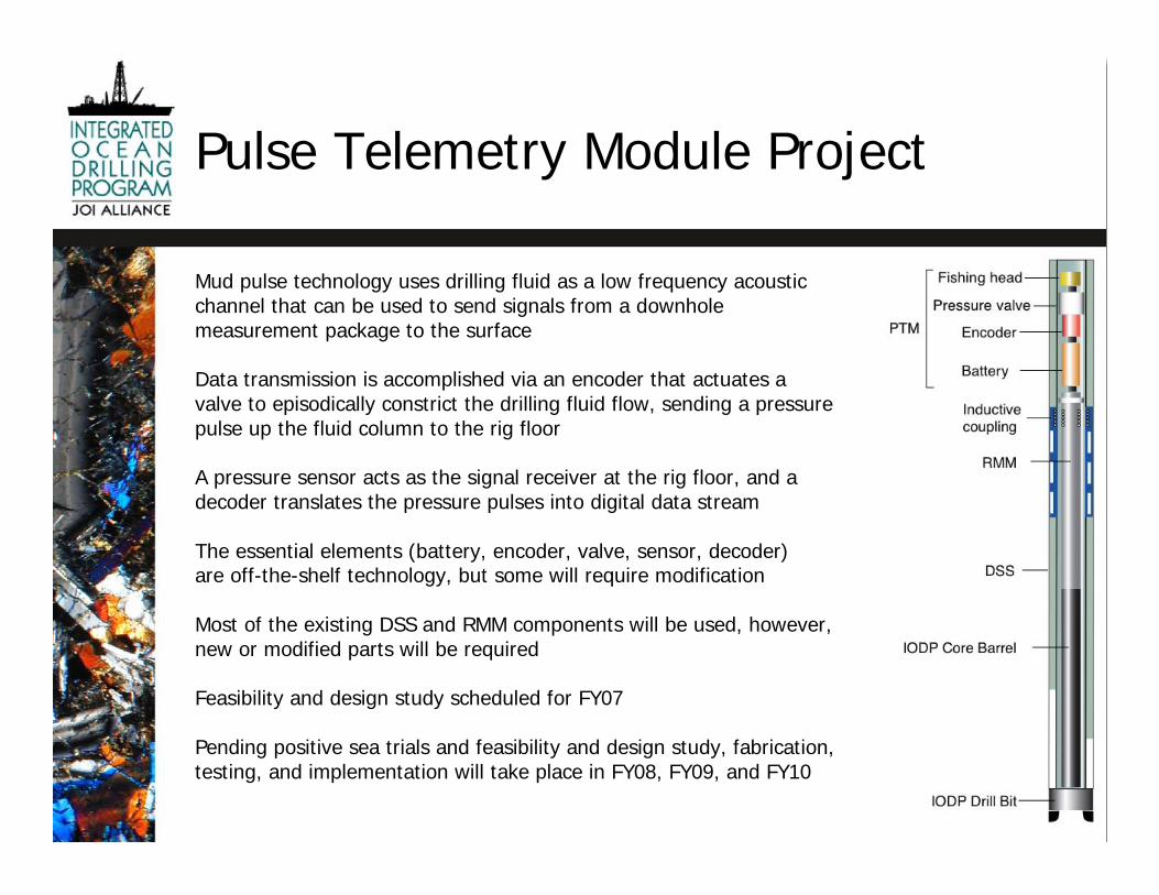
Pulse Telemetry Module Project
Mud pulse technology uses drilling fluid as a low frequency acousticchannel that can be used to send signals from a downholemeasurement package to the surface
Data transmission is accomplished via an encoder that actuates avalve to episodically constrict the drilling fluid flow, sending a pressurepulse up the fluid column to the rig floor
A pressure sensor acts as the signal receiver at the rig floor, and adecoder translates the pressure pulses into digital data stream
The essential elements (battery, encoder, valve, sensor, decoder)are off-the-shelf technology, but some will require modification
Most of the existing DSS and RMM components will be used, however,new or modified parts will be required
Feasibility and design study scheduled for FY07
Pending positive sea trials and feasibility and design study, fabrication,testing, and implementation will take place in FY08, FY09, and FY10

Project fit with ISP objectives
Real time monitoring of borehole conditions allows the driller to makeadjustments to drilling parameters, thereby enhancing drilling effectiveness
Annulus pressure can be used to identify downhole problems before theyhalt progress
Well control and downhole safety issues can be monitored
Heave compensation monitoring may lead to enhanced coring tooldevelopment
The pulse telemetry system can be deployed on other IODP platforms
Potential improvements in core recovery and quality has direct applicationto all three themes and eight initiatives of the Initial Science Plan

Project risk assessment
Feasibility study could demonstrate commercially available systemsare not applicable to our environmentRisk level: Low-technology is mature, several potential vendorsMitigation: Requires assessment of unique development potential
Resource loading owing to SODV implementation may result indevelopment delaysRisk level: Moderate-SODV resource loading still undeterminedMitigation: Development may extend past FY10
DSS or RMM can’t be incorporated into the systemRisk level: Low-RMM is ready for sea trials, DSS is scheduled for land testsMitigation: Positive results from land tests, sea trials, and feasibility studyall required before project initiation

CYFY
Task Time M J J A S OND J F MA MJ J A S OND J F MA MJ J J A S OND J F MJ JEDP review of feasibility study 2 mDetailed design 3 mPrepare SOW/RFQ for manufacture 2 mCirculate RFQ to manufacturers 1 mEvaluate responses to RFQ 1 mAward contract <1 mBuild 5 mRebuild RMM 4 mTesting and documentation 18 mAcceptance 1 mImplementation <1 m
PTM module development
Task CY=calendar yearMilestone FY=fiscal yearCompletion
2008 20092008 2009
20102010
2007
Project timeline

Project budget
USIO FY08 PTM Budget EstimateServices $51,000 Integration design, testing, machining of mechanical interfacesEquipment $145,000 Pulser, BHA, surface box, stock, electronics, software, toolingSupplies $7,000 Test equipment, toolsShipping $4,500 Field testTravel $13,000 Vendor meetings, field testOverhead $18,815TOTAL $239,315USIO FY09 PTM Budget EstimateServices $12,000 Test facilities, machining of mechanical interfacesEquipment $22,000 Test hardware, stock, electronics, software, toolingSupplies $1,500 Test equipment, toolsShipping $4,500 Field testTravel $10,000 Vendor meetings, field testOverhead $5,300TOTAL $55,300USIO FY10 PTM Budget EstimateServices $82,000 Sea trials with service engineer, design upgradesEquipment $156,000 Second system, modifications to first systemSupplies $1,500 Test equipment, toolsShipping $7,500 Field test, sea trialTravel $13,000 Vendor meetings, field test, sea trialsOverhead $5,300TOTAL $265,300

APPENDIX 13

USIO Technology RoadmapConcept - Create a planning tool that articulates short and long termengineering developments required to deliver the science objectives of theIODP Initial Science Plan
Goals -Coordinate the USIO technology roadmap with SAS advisorypanel visions for technology development
Engage stakeholders in prioritization of technology developments
Foster and maintain collaboration among the IODP ImplementingOrganizations

USIO Technology Roadmap
• What are the most significant scientific objectives ineach of the themes of the IODP ISP that scientific oceandrilling has not been able to achieve owing totechnological limitations?
• What are the essential research and development areasthat require focus to reach these objectives?
• What are the priorities in technology development forthe USIO?
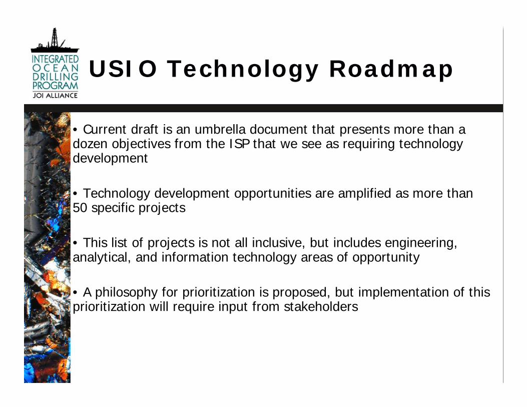
• Current draft is an umbrella document that presents more than adozen objectives from the ISP that we see as requiring technologydevelopment
• Technology development opportunities are amplified as more than50 specific projects
• This list of projects is not all inclusive, but includes engineering,analytical, and information technology areas of opportunity
• A philosophy for prioritization is proposed, but implementation of thisprioritization will require input from stakeholders
USIO Technology Roadmap

USIO Technology Roadmap
Projects with potential investment from EDP
Long-term observatories Depth determination
Paleomagnetic overprint Core orientation
Drilling young oceanic crust Rig instrumentation
Heave compensation Pulse telemetry
Directional drilling Deep drilling
Common BHA Seafloor visualization
In situ formation characterization
Downhole tools calibration and testing facility
Hard rock coring engineering developments
Maintaining subseafloor physical conditions during sample recovery and handling
Poor recovery in weakly consolidated or friable material and variable hardness lithologies
In situ high-temperature fluid sampling and temperature measurement

APPENDIX 14
IODP-USIO Report
EDP Meeting
Windischeschenbach, Germany
27-29 June, 2006
IODP Coring Tools

Coring Tools
• Standard Coring Systems– Advanced Piston Corer (APC)– Extend Core Barrel (XCB)– Rotary Core Barrel (RCB)
• Specialty Coring Systems– Pressure Coring System (PCS)– Advanced Diamond Core Barrel (ADCB)– Motor Driven Core Barrel (MDCB)

APC
• Description– Collects 9.5 m long, 62mm (2.44”),
oriented cores from very soft to firmsediments
– Wireline deployed and recovered– APC Temperature tool may be run to
obtain in situ heat flow measurementswith no interruption of coring operations
• Limitations– Does not penetrate or recover granular
formations (sand and gravel)– Core barrel may stick in firm sediments
requiring drill-over
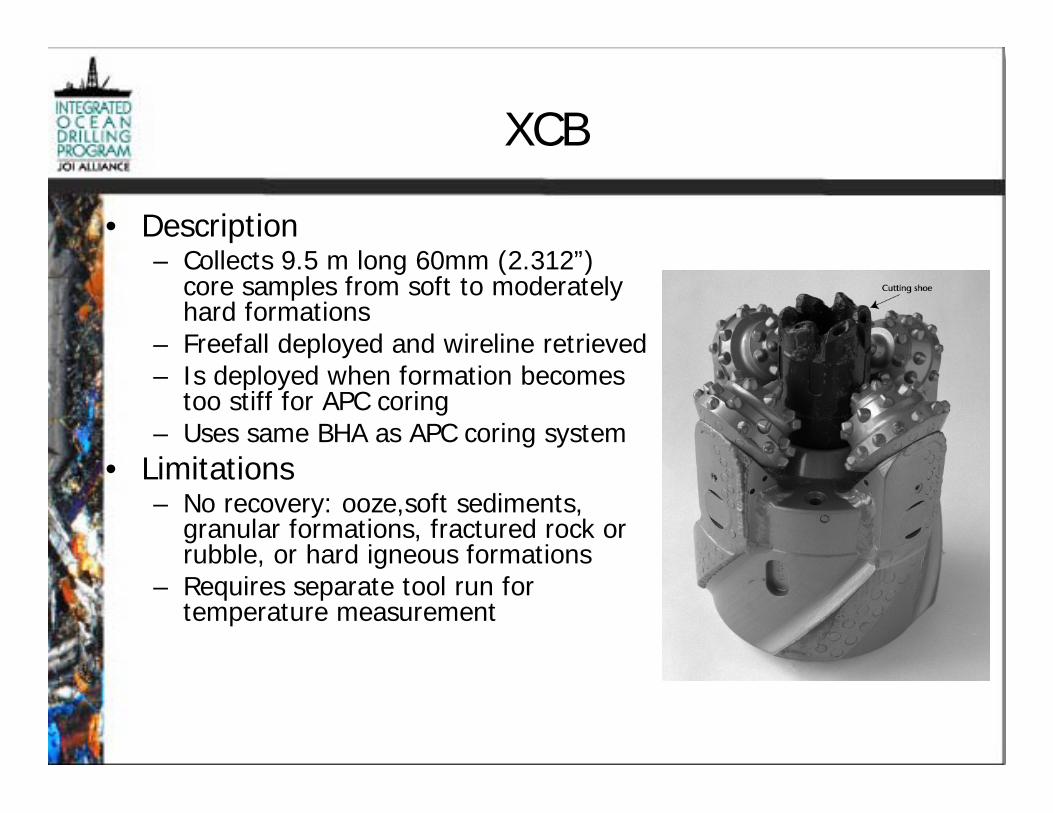
XCB
• Description– Collects 9.5 m long 60mm (2.312”)
core samples from soft to moderatelyhard formations
– Freefall deployed and wireline retrieved– Is deployed when formation becomes
too stiff for APC coring– Uses same BHA as APC coring system
• Limitations– No recovery: ooze,soft sediments,
granular formations, fractured rock orrubble, or hard igneous formations
– Requires separate tool run fortemperature measurement

RCB
• Description– Collects 9.5 m long, 60 mm (2.312”)
samples from firm to hard sedimentsand igneous basement
– Freefall deployed and wireline retrieved– Deployed when formation becomes too
stiff for XCB coring• Limitations
– Does not recover soft sediments orgranular formations (sand, fracturedrock or rubble)
– Requires separate tool run fortemperature
– Requires pipe trip if using APC/XCB– Requires pipe trip for logging if
mechanical bit release is not used

PCS
• Description– Collects 1 m long 43.2 mm (1.70”) core
at in-situ pressure (10,000 psi)– Freefall deployed and wireline retrieved– System is rotated with bit– Used for targeted areas in formation– Compatible with APC/XCB BHA
• Limitations– Limited to soft sediments to firm clay– No transfer method to autoclave– Small core size may impact sampling

ADCB
• Description– Designed to improve recovery in hard
formations; recovers either 4.75 or 9.5 m long83 mm (3.27”) cores; diameter increases to 85mm (3.345”) when run without a liner
– Freefall deployed and wireline retrieved– Creates powder cuttings–requires less fluid
velocity; core is not directly exposed to highpressure fluids
• Limitations– Recommend core length of 15’ (4.75m) to
reduce core jamming and weight.– Does not recover soft sediment and granular
formations– Not recommended for bare rock spud– Requires good WOB control– Requires different BHA than other coring
systems– Depth is limited to the length of 6-3/4” drill
collars available

MDCB
• Description– Designed to retrieve 4.5 m long, 57 mm
(2.25”) core in formations difficult toAPC/XCB core (fractured crystalline rock,interbedded hard/soft formations, friableconglomerate and reef materials)
– Wireline deployed and retrieved– Rotates inner core barrel and cutting shoe
with mud motor– Thruster section uses hydraulic force to
provide WOB to advance inner core barrel– Can be alternated with APC/XCB systems– Compatible with APC/XCB BHA
• Limitations– Works poorly in unconsolidated granular
formations– Short core length requires more wireline
time than typical systems– Requires more wireline and handling time
than typical coring systems

APPENDIX 15
IODP-USIO Report
EDP Meeting
Windischeschenbach, Germany
27-29 June, 2006
Engineering Projects Report

Engineering Projects-FY06
• Riverside Test Facility• Simulated Borehole Test Facility (SBTF)• Calibration Facility• Ongoing Projects
– Motor Driven Core Barrel (MDCB)– Davis Villinger Temperature Probe (with Pressure) (DVTP/P)– Instrumented Water Sampler (IWS)– Common Data Logger– Downhole Sensor Sub/Retrievable Memory Module (DSS/RMM)– Modular Temperature Tool (MTT)
• Expedition Planning– NanTroSEIZE 2– Juan de Fuca II

Testing Facilities
• Riverside Test Facility– Prepare areas for use with SBTF
• SBTF– Develop method of consolidating sediments for use in testing– Purchase equipment for mixing and consolidating clay

Testing Facilities (cont.)
• Calibration Labs– Climate controlled
temperature andpressure
– Purchase additionalcalibration equipment
– Re-certify dead weighttester and temperaturecalibration equipment
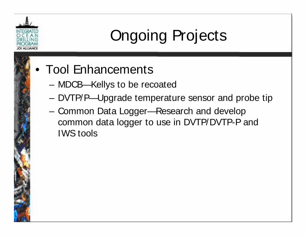
Ongoing Projects
• Tool Enhancements– MDCB—Kellys to be recoated– DVTP/P—Upgrade temperature sensor and probe tip– Common Data Logger—Research and develop
common data logger to use in DVTP/DVTP-P andIWS tools

Ongoing Projects (cont.)
• DSS– Complete acceptance
testing for WOB andTOB measurements
– Testing tentativelyscheduled for midSeptember atSchlumberger facility inSugar Land, TX
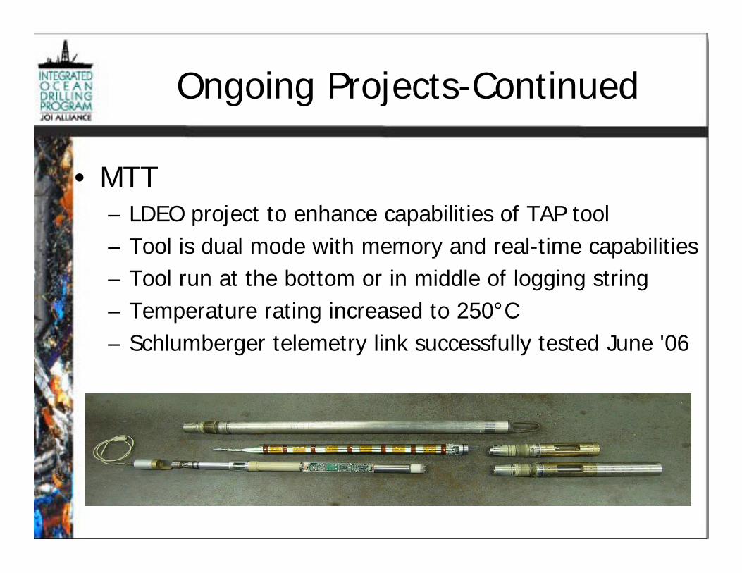
Ongoing Projects-Continued
• MTT– LDEO project to enhance capabilities of TAP tool– Tool is dual mode with memory and real-time capabilities– Tool run at the bottom or in middle of logging string– Temperature rating increased to 250°C– Schlumberger telemetry link successfully tested June '06

Expedition Planning
• NanTroSEIZE 2– Design ACORK/CORK II for
NanTroSEIZE 2 IODP Phase II– Design review in Aug. '06
• Juan de Fuca II– Design CORK II for IODP Phase II
Juan de Fuca II Expedition– Include design of free flow CORK II
head and 10-3/4” – 16” casing seal– Tom Pettigrew contracted for design
work—design review scheduled forAug. ‘06

Engineering Projects-FY07
• Riverside Test Facility– SBTF: test temperature and pressure tools– Dynamometer: order equipment to make it operational
• Tool Enhancements– Two year project to:
• Enhance Pressure Core Sampler (PCS) temperature/pressuremeasurements
• Redesign IWS hardware and electronics
– Design/purchase test equipment for Hydraulic PistonDelivery System (HPDS)
– Upgrade electronics on APCM, DVTP/DVTP-P and IWS– Purchase 3rd party equipment to test/evaluate APCT-3

Engineering Projects-FY07 (cont.)
• Calibration Labs– Calibrate lab equipment
• Pulse Telemetry Module (PTM)– Contract PTM feasibility study for use with DSS and
RMM to provide real time WOB and TOB data whilecoring
• Expedition Planning– Begin purchasing long lead hardware for
NanTroSEIZE 2 and Juan de Fuca II CORKs

Engineering Projects-FY08
• Riverside Test Facility– SBTF: test temperature, pressure, and fluid sampling tools– Dynamometer: complete and commission for operation
• Tool Enhancements– PCS: purchase 3 new tools and spares– IWS: purchase 2 new tools and spares
• Development Projects– Pulse Telemetry Module: purchase for use with DSS and RMM
• Expedition Planning– Purchase remaining hardware for NanTroSEIZE 2 and Juan de Fuca II
CORKs

APPENDIX 16

Engineering, Analytical, and Information Technology Developments for 21st Century Scientific Ocean Drilling US Implementing Organization (USIO) Technology Roadmap Table of Contents I. SUMMARY
II. INTRODUCTION
II.A. Concept
II.B. Scope
III. CHALLENGING OBJECTIVES OF THE IODP INITIAL SCIENCE PLAN
III.A. The deep biosphere and the subseafloor ocean
III.A.i. Global assay of microbiological activity
III.A.ii. Long-term observatories
III.A.iii. Archiving microbiological observations and data
III.A.iv. Sampling in extreme environments
III.B. Environmental change, processes, and effects
III.B.i. Depth measurement
III.B.ii. Multiple depth scales for data analysis
III.B.iii. Age-depth modeling
III.B.iv. Paleomagnetic overprint
III.B.v. Poor recovery in weakly consolidated or friable material and variable hardness lithologies
III.B.vi. In situ fluid sampling capability
III.C. Solid earth cycles and geodynamics
III.C.i. Core orientation
III.C.ii. Drilling young oceanic crust
III.C.iii. Core description software
IV. TECHNOLOGY OPPORTUNITY AREAS
IV.A. Long-term observatories
IV.A.i. Cementing completions and casing seals
IV.A.ii. CORKS
IV.A.iii. Multizone sampling
IV.A.iv. Fluid sampling
Roadmap_rev2_5APP16.doc 1 7/17/2006

IV.A.v. Deviated hole completions
IV.B. Maintaining subseafloor physical conditions (temperature, pressure, etc.) during sample recovery and handling
IV.B.i. Pressurized sample transfer
IV.B.ii. Instrumented pressure coring system
IV.C. Depth determination
IV.C.i. Heave compensation during piston coring
IV.C.ii. Automated pipe length determination
IV.D. Paleomagnetic overprint
IV.E. Poor recovery in weakly consolidated or friable material and variable hardness lithologies
IV.E.i. XCB and MDCB coring systems
IV.E.ii. Vibracoring
IV.E.iii. Sonic coring
IV.F. In-situ high-temperature fluid sampling and temperature measurement
IV.G. Core orientation
IV.G.i. APC core orientation
IV.G.ii. XCB/RCB core orientation
IV.H. Drilling young oceanic crust
IV.I. Downhole tools calibration and testing facility
IV.J. Rig instrumentation
IV.K. Heave compensation
IV.L. Pulse telemetry
IV.M. Directional drilling
IV.N. Deep drilling
IV.O. Common BHA
IV.P. In situ formation characterization
IV.P.i. Intellipipe
IV.P.ii. Large-diameter logging tool conduit
IV.P.iii. LWD/MWD/LWC
IV.P.iv. Powered coring line
IV.P.v. Instrumented core barrels
IV.Q. Seafloor visualization
Roadmap_rev2_5APP16.doc 2 7/17/2006

IV.R. Hard rock coring engineering developments
IV.R.i. Hard rock reentry system
IV.R.ii. Hammer to drive casing
IV.R.iii. Advanced diamond core barrel
IV.S. Global assay of microbiological activity
IV.T. Depth modeling
IV.U. Laboratory Information Management System
IV.V. Automated core handling and characterization
IV.V.i. Hyperspectral measurement
IV.V.ii. Nuclear magnetic resonance analysis
IV.V.iii. X-ray computer-assisted tomography
IV.V.v. Laser-induced breakdown spectroscopy
IV.V.vi. Automated elemental analysis of cores
IV.W. Laboratory core measurements at temperature and pressure
IV.X. Archiving microbiological observations and data
IV.Y. Core description software
IV.Z. Keeping up with technological developments in data processing and storage
V. PRIORITIZATION OF TECHNOLOGY DEVELOPMENT
V.A. Prioritization Criteria
V.B. Stakeholder Involvement
VI. CONCLUSION
Roadmap_rev2_5APP16.doc 3 7/17/2006

I. SUMMARY
In response to recognition of resource limitations and strategic planning requirements and to coordinate with similar activities in the Integrated Ocean Drilling Program (IODP) Science Advisory Structure (SAS), the IODP U.S. Implementing Organization (IODP-USIO; herein after referred to as the USIO) has developed a technology roadmap for immediate and long-range planning. This roadmap follows a path of articulating challenges, identifying hurdles, and paving the way forward via prioritization. The ultimate goal of this roadmap is delivery of the scientific objectives of the IODP Initial Science Plan (ISP). The roadmap outlines objectives within the themes of the ISP and offers a series of potential technology developments. The roadmap concludes with consideration of how we expect to prioritize technology developments and engage our community of stakeholders. This report is a snapshot of our current thinking; however, we expect this technology roadmap to be a living document, continually evolving to meet the needs of scientific ocean drilling in the 21st Century. II. INTRODUCTION
II.A. Concept
Technology Roadmapping is a technology management and planning tool that has been widely adopted in industry to support technology development. Various forms of roadmaps have been successfully implemented, and many of these models share the following key elements. First, they define the problem(s) to be addressed via technology development. Then, they identify the key technological hurdles that must be overcome. Finally, they develop a set of criteria for prioritization of technology development. In its most basic form, the nucleus of a technology roadmap is recognition of temporal and resource requirements to deliver a certain objective or series of objectives. In simplest terms, a technology roadmap is a communication tool that allows stakeholders to visualize the evolution of technology development in an organization.
For the USIO, this technology roadmap is framed around three principal questions:
• What are the most significant scientific objectives in each of the themes of the IODP ISP that scientific ocean drilling has not been able to achieve owing to technological limitations?
• What are the essential research and development areas that require focus to reach these objectives?
• What are the priorities in technology development for the USIO?
II.B. Scope
This roadmap articulates a multiphase approach toward implementing technology development. In the framework of this roadmap, short-term developments include those that can be planned and delivered within a current annual program planning cycle (1–3 years). Long-term developments include those that require more time (2–5 years or more)
Roadmap_rev2_5APP16.doc 4 7/17/2006

and resources, are more complex, and/or are simply not ready to commence in the short term.
We envision this roadmap to be a living, evolving document, regularly updated as technology is delivered and new developments are considered. The initial release of this roadmap highlights projects identified by the USIO as important for improved science and operations, however, this list is not all inclusive. We encourage all stakeholders to contribute to the creation, review, and evolution of this roadmap, which will be available to our advisory structure in electronic form through the USIO Web portal (www.joialliance.org). We also envision this roadmap as a tool to foster and maintain coordination among the IODP Implementing Organizations.
This technology roadmap is not a project management tool. Separate planning groups will be created and documents generated to address research, design, and implementation of solutions to technology challenges described in the roadmap. III. CHALLENGING OBJECTIVES OF THE IODP INITIAL SCIENCE PLAN
The following section includes brief overviews of the status of scientific objectives outlined in the IODP ISP that are to be addressed in this technology roadmap. These objectives are sorted by the primary themes of the ISP, and no priority is implied. Many of the technological developments presented below have application to more than one theme of the ISP. III.A. The deep biosphere and the subseafloor ocean
III.A.i. Global assay of microbiological activity
Two primary scientific objectives have been defined by the IODP microbiological community (articulated in the minutes of the Fall 2006 Science Steering and Evaluation Panel [SSEP] microbiology meeting). These are site- or region-specific microbiological studies and a global reconnaissance of subseafloor microbiology. Whereas the first will be developed on a case-by-case basis within the proposal protocols of IODP, the second objective is a legacy issue that should be developed and employed by the program. To date, no protocols exist for standard, routine sampling and sample processing of microbiological samples. In addition, no technical support is routinely allocated to microbiology. Technical support has only been provided on an ad hoc basis.
III.A.ii. Long-term observatories
CORK designs and installations have become increasingly more complex since their initial deployment during the Ocean Drilling Program (ODP) in the early 1990s. As an example, recent deployments have included passive microbiological samplers. New developments will include active experimentation and will require both analytical and engineering support to ensure compatibility with hardware and other experiments. Other issues that require development also include cementing programs and casing seal strategies.
Roadmap_rev2_5APP16.doc 5 7/17/2006

III.A.iii. Archiving microbiological observations and data
No system of data acquisition or archiving exists within IODP for microbiological data.
III.A.iv. Sampling in extreme environments
Two types of extreme environments in the subseafloor ocean have been the focus of scientific investigation in the last decade and will continue to be areas of interest throughout the tenure of IODP. Moderate- to high-temperature (70°C to >350°C) hydrothermal systems are known to host diverse ecosystems where chemosynthesis plays an important role in biological energetics. Sources of heat have been ascribed to magmatic activity and to the exothermic reaction of serpentinization of mantle peridotite uplifted to at or near the seafloor. Either source contributes unique conditions for biogeochemical investigations. Drilling, coring, and sampling tools for high-temperature environments have not reached mature status.
Exploration of another type of extreme environment, cold seafloor hydrocarbon seeps and subseafloor gas hydrates deposits, has generated tremendous scientific interest. A unique biological system and potential climatic impact, as well as economic interest, will ensure continued interest in these environments. One of the most significant developments that would enhance subseafloor ocean microbiological science would be methodologies and protocols for delivery of subseafloor samples under in situ physical conditions. We have yet to assess or quantify the degradation of microbiological samples imparted by depressurization during core recovery and handling. Maintaining samples at in situ conditions is also crucial for gas hydrates research.
III.B. Environmental change, processes, and effects
III.B.i. Depth measurement
The primary reference for all coring operations is the cumulative length of the drill string below the rig floor. Actual drill pipe length determination is performed infrequently, with a reported precision of ~0.1 m. The actual error in drill pipe measurement and, hence, depth on an interval of core is significantly higher, on the order of 0.2–4 m or more owing to ship heave, pipe stretch and bend, ship position offset, and estimation of pipe position at the rig floor. No precise estimation of error in drill pipe depth is possible, but the magnitude of the error is demonstrated by the difference between precision depth recording devices and drill pipe measured depths, as well as the commonality of multiple adjacent drill pipe measurements that disagree by as much as a few meters. A primary obstacle to high-resolution depth estimation in piston coring is the requirement to lock out heave compensation before firing the advanced piston corer (APC). This action results in a significant, albeit unquantified, amount of motion at the bit (as much as vertical ship motion). Another outstanding example is the drill pipe-measured depth to the bottom of Hole 735B. This hole, drilled directly into hard rock
Roadmap_rev2_5APP16.doc 6 7/17/2006

basement, recorded a subbottom depth of 500.8 m at the termination of ODP Leg 118. During reoccupation 10 years later (ODP Leg 176), the drill pipe measurement to the bottom of the hole was in excess of 504 m. Accurate depth registration is fundamental to sedimentation rate calculations and any modeling based on the relationship between age and depth.
III.B.ii. Multiple depth scales for data analysis
Scientific ocean drilling achieves many of its objectives through integration of data sets that share the independent variable depth. Data obtained relative to different depth scales need to be mapped to each other as well as to data obtained relative to seismic traveltime or geologic age to achieve full data integration. Depth itself a function of different types of original measurement tools and techniques, such as acoustic methods, drill string length, and deployed lengths of different types of wirelines, each with its own set of uncertainties. Interval depth and continuous depth are distinguished where continuous depth of measurement points is only valid within a contiguous sample interval. For example, downhole measurements have a continuous depth scale within the contiguous sample interval “hole.” Contiguous core samples yield continuous scales with high accuracy and precision (centimeters) within the recovered core interval, but the relative accuracy and precision for the samples’ top depth reference (driller’s core-top datum) are much lower (meters). Continuous depth scales are usually distorted to some degree—downhole logging scales by differential friction and associated wireline stretch during logging and cores by differential compression during the piston coring process. Cores with lengths less than the drilled interval and/or cores that are fractured into pieces have continuous depth scales only within each piece—the relative depth within the cored interval and the location of missing material are usually unknown. Soft-sediment cores expand significantly during recovery as a result of elastic rebound and gas expansion, and they shrink during the analytical process as a result of drying. All these issues and phenomena need to be taken into account in the specification and implementation of a new depth scale framework, such that propagation of error in depth mapping procedures can be tracked.
IODP investigators must be able to construct, store, and retrieve multiple depth correlation maps, including all relevant metadata, based on any two user-defined data sets. Data query systems must allow the user to select among all available depth scales and apply the selected scale to any data set. Some analytical procedures to construct common depth scales for data sets, such as construction of composite depth intervals for cores from adjacent holes and stratigraphic splicing, have become quasi-standards in ODP and early IODP and need to be incorporated into the future IODP depth mapping standards. Processes applied less frequently during ODP, such as core-log and core-log-seismic integration are likely to increase in feasibility during IODP as new tools and platforms produce better data sets and more user-friendly analysis environments.
Roadmap_rev2_5APP16.doc 7 7/17/2006

III.B.iii. Age-depth modeling
Age-depth models have been generated for hundreds of ODP/IODP holes and sites, but no tools, protocols, or quality assurance/quality control (QA/QC) has ever been specified or provided for their construction. This lack has resulted in a legacy of highly variable approaches, presentations, metadata, and QC for age models among sites. Conflicting age models for single holes or sites have commonly been presented based on separate analyses of different data sets as opposed to an integrated analysis. The scientific party’s goal is to complete, by the end of an expedition, an integrated age-depth model that takes into account all available data and clearly presents uncertainties in age and depth and the assumptions used in the modeling. Furthermore, the age-depth maps should be saved to the database, along with appropriate metadata, and be available for automatic conversion of depth to geologic age in any data report. The most critical component missing today is a user-friendly modeling application that provides seamless access to all relevant data, a rich graphic interface, curve fitting options, resampling routines, etc.
III.B.iv. Paleomagnetic overprint
The history and challenges of drilling-induced magnetic overprint (DIMO) causes and attempts at solutions have been fairly well documented in manuscripts describing magnetic experiments from ODP Legs 146, 174B, 182, 189, and 202. DIMO has been interpreted to result from recovering cores in magnetized drill string components. The cause of drill string component magnetization has been attributed to routine jarring, vibrations, and rotational stresses imparted during drilling operations. Options to mitigate DIMO range from continual degaussing of the drill string to replacing some or all drill string components with nonmagnetic materials.
III.B.v. Poor recovery in weakly consolidated or friable material and variable hardness lithologies
Historically, one of the most technologically challenging operations faced during seafloor drilling is poor recovery in weakly consolidated or friable material or through intervals of variable hardness lithologies. For example, poorly cemented carbonate grainstones can be completely ground up in the borehole because the weight of the drill string exceeds the strength of the lithologic fabric. Unconsolidated material without sufficient binding agent is challenging to recover without disturbance or loss of material through the core catcher. In highly porous formations, it is problematic to determine actual recovery rates (i.e., how much of the formation was actually pore space and does the amount of material recovered reflect the true distribution of rock and void space?). In formations where alternate hardness materials are intercalated at intervals less than the length of a coring interval, recovery suffers because coring tools optimized for one lithology are commonly not optimized for others (e.g., chalk-chert sequences). Even if the alternation intervals are thick, predicting a change in hardness or drilling characteristics to allow for exchange of coring technology is not commonly practical.
Roadmap_rev2_5APP16.doc 8 7/17/2006

III.B.vi. In situ fluid sampling capability
Technology developed during ODP includes tools designed for formation and borehole fluid sampling. Different iterations of these types of devices have been implemented, but they all suffer from the similar dilemma of penetrating the formation with a probe (while not allowing borehole fluid to leak along the probe), holding the probe in place while formation fluid is drawn into the tool (without contamination or suction, which could cause a change in the physical properties of the fluid), and maintaining the fluid at in situ conditions during recovery.
III.C. Solid earth cycles and geodynamics
III.C.i. Core orientation
A longstanding objective of scientific ocean drilling has been to apply structural reorientation to recovered cores. In high-recovery, sediment-type projects, core orientation is primarily used to normalize the relative paleomagnetic pole directions relative to the current absolute pole direction. Measurements of relative orientation of stratigraphic and deformational structures can then be converted to absolute orientation as well.
Although logging data can provide an indirect, relative orientation based on correlation of corresponding features measured in cores and downhole, because of incomplete recovery correlation between specific intervals of rock and logging data provides nonunique solutions.
Designs for hard rock core orientation were tested during ODP but required multiple systems working in coordination to function. Full orchestration was never realized before the project was shelved owing to refocusing of limited engineering resources.
III.C.ii. Drilling young oceanic crust
In the history of ocean drilling, scientists have had virtually no success in coring young oceanic crust. Dozens of attempts (the most recent during ODP Leg 209 and IODP Expedition 304) were typical examples of a few meters penetration and less than a few percent recovery before holes were abandoned. The general dogma is that the rubbly topography associated with morphologically youthful basaltic traps the bit, increasing torque to unacceptable levels. Drilling in young basalts has been phenomenally successful in Hawaii and functionally routine in geothermal applications in Iceland.
III.C.iv. Core description software
This particular development has overarching applicability to all themes of the ISP. One of the most fundamental records developed during any IODP expedition is the observations of macroscopic and microscopic characteristics of the recovered cores. Commonly referred to as visual core descriptions, these records range from a general overview of features visible in hand specimens to submillimeter petrologic details. Historically, the data capture and archive systems for the core description process have
Roadmap_rev2_5APP16.doc 9 7/17/2006
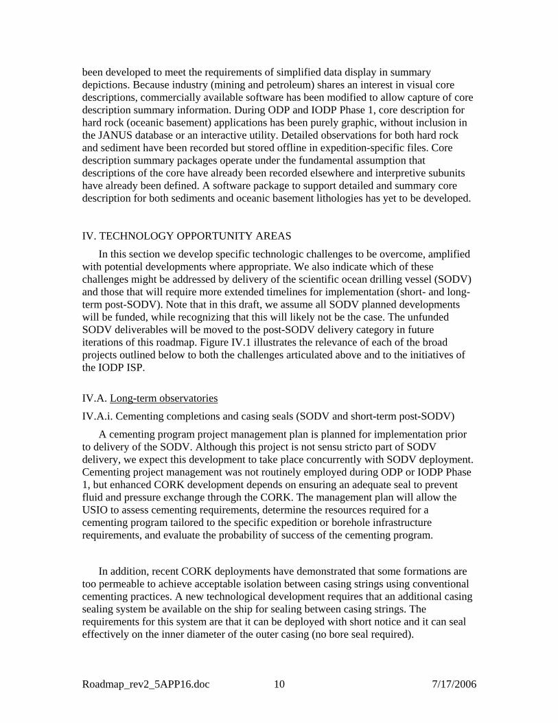
been developed to meet the requirements of simplified data display in summary depictions. Because industry (mining and petroleum) shares an interest in visual core descriptions, commercially available software has been modified to allow capture of core description summary information. During ODP and IODP Phase 1, core description for hard rock (oceanic basement) applications has been purely graphic, without inclusion in the JANUS database or an interactive utility. Detailed observations for both hard rock and sediment have been recorded but stored offline in expedition-specific files. Core description summary packages operate under the fundamental assumption that descriptions of the core have already been recorded elsewhere and interpretive subunits have already been defined. A software package to support detailed and summary core description for both sediments and oceanic basement lithologies has yet to be developed. IV. TECHNOLOGY OPPORTUNITY AREAS
In this section we develop specific technologic challenges to be overcome, amplified with potential developments where appropriate. We also indicate which of these challenges might be addressed by delivery of the scientific ocean drilling vessel (SODV) and those that will require more extended timelines for implementation (short- and long-term post-SODV). Note that in this draft, we assume all SODV planned developments will be funded, while recognizing that this will likely not be the case. The unfunded SODV deliverables will be moved to the post-SODV delivery category in future iterations of this roadmap. Figure IV.1 illustrates the relevance of each of the broad projects outlined below to both the challenges articulated above and to the initiatives of the IODP ISP.
IV.A. Long-term observatories
IV.A.i. Cementing completions and casing seals (SODV and short-term post-SODV)
A cementing program project management plan is planned for implementation prior to delivery of the SODV. Although this project is not sensu stricto part of SODV delivery, we expect this development to take place concurrently with SODV deployment. Cementing project management was not routinely employed during ODP or IODP Phase 1, but enhanced CORK development depends on ensuring an adequate seal to prevent fluid and pressure exchange through the CORK. The management plan will allow the USIO to assess cementing requirements, determine the resources required for a cementing program tailored to the specific expedition or borehole infrastructure requirements, and evaluate the probability of success of the cementing program.
In addition, recent CORK deployments have demonstrated that some formations are too permeable to achieve acceptable isolation between casing strings using conventional cementing practices. A new technological development requires that an additional casing sealing system be available on the ship for sealing between casing strings. The requirements for this system are that it can be deployed with short notice and it can seal effectively on the inner diameter of the outer casing (no bore seal required).
Roadmap_rev2_5APP16.doc 10 7/17/2006

Challenging objectives of the IODP ISP ISP initiatives
Roadmap Project Glo
bal a
ssay
of
mic
robi
olog
ical
act
ivity
Lon
g te
rm o
bser
vato
ries
Mic
robi
olog
y da
ta
Ext
rem
e en
viro
nmen
ts
Age
-dep
th r
esol
utio
n an
d m
odel
ing
Pale
omag
netic
ove
rpri
nt
Poor
ew
cove
ry
In-s
itu fl
uid
sam
plin
g
Cor
e or
ient
atio
n
You
ng o
cean
ic c
rust
Cor
e de
scri
ptio
n
Dee
p bi
osph
ere
Gas
hyd
rate
sE
xtre
me
clim
ate
Rap
id c
limat
e ch
ange
Con
tinen
tal b
reak
upL
arge
igne
ous p
rovi
nces
Moh
oSe
izm
ogen
ic z
one
Long term observatoriesMaintaining subseafloor physical conditionsDepth determinationPaleomagnetic overprint Poor recovery High-temperature fluid sampling and temperature measurement Core orientation Drilling young oceanic crust Downhole tools calibration and testing Rig instrumentation Heave compensation Pulse telemetry Directional drilling Deep drilling Common BHA In-situ formation characterizationSeafloor visualization Hard rock coring engineering Global assay of microbiological activity Depth modelingLaboratory Information Management System Automated core handling and characterization Core measurements at in situ temperature and pressure Archiving microbiological observations Core description software Measurements at in-Situ temperature and pressureDatabase infrastructure development
Figure IV.1. Roadmap projects mapped to relevance to articulated challenging objectives of the IODP ISP and ISP initiatives. Shaded box indicates relevance of project to objective or initiative.
IV.A.ii. CORKS (SODV and short- to long-term post-SODV)
Again, not directly a deliverable of SODV but as a concurrent development, a new generation of CORK technology is required to meet the scientific objectives of currently scheduled expeditions. We recognize each CORK deployment is likely to result in more technologically challenging developments. A scheduled, short-term post-SODV deployment requires engineering development to nest a CORKII inside an instrumented ACORK and to monitor conditions inside and outside the casing.
IV.A.iii. Multizone sampling (long-term post-SODV)
The next generation of hydrologic observations and envisioned active subseafloor experimentation will require the technology to isolate and subsample multiple horizons
Roadmap_rev2_5APP16.doc 11 7/17/2006

within a single borehole. Cross hole and vertical flow experiments are planned early in Phase 2. Engineering development is required to craft a complete borehole installation, particularly in a hydrologically complex and/or deepwater and/or thick sediment environment.
IV.A.iv. Fluid sampling (long-term post-SODV)
Innovations in sampler design from probe tip geometry (less formation damage), passive fluid extraction (to prevent fluid/gas flashing), and heave compensation improvement (to keep the probe tip in continuous contact with the formation) are all requirements of the next generation of formation fluid samplers. Additional technological improvements beyond fluid sampling include measuring temperature and pressure with a single probe.
IV.A.v. Deviated hole completions (long-term post-SODV)
Common industry practice (and an envisioned technological requirement for deep-penetration holes) requires multiple deviations in a single borehole. Intentional deviation has not been a routine engineering practice in scientific ocean drilling and will require engineering technology development, particularly if we consider continuous coring a probability. Potentially, each deviation will require specific technological developments for isolation, monitoring, and sampling.
IV.B. Maintaining subseafloor physical conditions (temperature, pressure, etc.) during sample recovery and handling
IV.B.i. Pressurized sample transfer (long-term post-SODV)
The most gargantuan technological hurdle to overcome in subseafloor microbiological investigations is maintaining in situ conditions when transferring cores from the collection point to the laboratory. Because no sample has ever been recovered at in situ conditions, held at those conditions, and manipulated in the laboratory without altering these intensive parameters, we cannot evaluate the deleterious effects this process has on microbial populations. Similarly, engineering development in maintaining core pressurization is required to continue to accommodate future gas hydrates research.
IV.B.ii. Instrumented pressure coring system (long-term post-SODV)
Successful deployments of the pressure coring system (PCS) during several gas hydrates drilling programs have engendered a requirement for more technological development of this system. The next version of the PCS needs to include monitors to evaluate changes in the core sample concomitant with recovery and delivery to the laboratory.
Roadmap_rev2_5APP16.doc 12 7/17/2006

IV.C. Depth determination
IV.C.i. Heave compensation during piston coring (long-term post-SODV)
Historic discussion on this issue has revolved around the potential of compensating the coring line, but the root issue is mitigating bit motion during the piston coring process. Our current system requires shutting down heave compensation as the hydraulic piston core is charged and fired. During this process, the bit responds to vertical ship motion, and ascertaining bit depth at the moment the piston fires has an error roughly equivalent to that of bit travel. The result is poor absolute depth resolution and repeated or missing sediment sequences. This development may require a complete reengineering of our hydraulic piston coring system.
IV.C.ii. Automated pipe length determination (long-term post-SODV)
Current practice for measuring the depth of the bit below rig floor is to physically measure (strap) the length of each joint of pipe and to tally these individual lengths as each joint or stand of pipe is added. This process has been automated in industry via the use of radio frequency identification devices (RFIDs) RFID tags are embedded in the tool joint of each length of pipe, precoded with several types of information including length. As the tool joint passes a sensor on the rig floor, the length is uploaded to an automated accounting system, thus eliminating potential operator error in pipe length determination. Additional information can also be encoded including pipe wear and number of deployments. These data can potentially be used to prolong pipe utility through preventative maintenance programs.
IV.D. Paleomagnetic overprint (short-term post-SODV)
Degaussing the drill string via an alternating-field (AF) coil mounted beneath the rig floor was attempted during the Deep Sea Drilling Program (DSDP). The coil was destroyed fairly quickly during operations, and the analysts interpreted that inasmuch as the pipe was exposed to additional stresses on each deployment this was probably a fruitless endeavor.
Replacing drill string components with nonmagnetic materials has been tested on several expeditions. Basically, the important characteristic of materials used for this purpose is magnetic permeability. Magnetic permeability of some materials is listed in Table IV.1.
Table IV.1. Magnetic permeability and yield strength of materials.
Material Magnetic
permeability Approximate yield
strength (MPa) Cost/cost of iron Titanium 1.00005 950 2500 Monel 1.002 100–150 4000 Stainless steel 1.008 500–600 700 Iron 150 300–500 1 Silicon iron (4% Si) 500 No data No data
Roadmap_rev2_5APP16.doc 13 7/17/2006
The most radical solution could be to replace the entire drill string and all components with nonmagnetic material. It is not likely that a nonmagnetic drill string is readily available. Current searches for nonmagnetic or low-magnetic permeability materials yield few results but include titanium, monel (a compound of predominantly nickel with copper, iron, and manganese), and some varieties of stainless steel. Costs of raw metal/alloys relative to iron are listed in Table IV.1. Considering an iron drill string costs in excess of $1 million, none of the other nonmagnetic components are feasible in terms of cost, even if an interested vendor could be located.
Recent studies have concluded that restricting the amount of time the core is in contact with the core barrel as well as employing core capture components fabricated from nonmagnetic materials significantly reduces the strength of the viscous remanent magnetization induced in the core. Nonmagnetic core capture components have been fabricated for APC coring tools; however, similar technology has not been developed for the extended core barrel (XCB), rotary core barrel (RCB), or alternative coring tools.
IV.E. Poor recovery in weakly consolidated or friable material and variable hardness lithologies (long-term post-SODV)
IV.E.i. Extended core barrel and motor-driven core barrel coring systems
The XCB coring assembly operates very well in most cases, but when coring through hard, dry clay the nozzles plug, preventing circulation on the cutting face. The plugged nozzles result in overheating, destroying the cutting structure. Suggestions for solving this problem include redesigning the coring shoe and providing automatic valves to maintain nozzle velocity and/or powering the XCB shoe with a positive displacement motor independent of the XCB bit. The current motor-driven core barrel (MDCB) has been infrequently used. Because the MDCB coring assembly advances by a thruster out through the stationary XCB bottom-hole assembly (BHA), the driller cannot monitor the weight on bit (WOB) of the MDCB cutting shoe. MDCB WOB is controlled by pump pressure, but because the flow is relatively low variations in pump pressure do not clearly indicate WOB or even motor stalling. The solution to this problem may require instrumentation that can track the stroke of the MDBC and transmit the information uphole.
IV.E.ii. Vibracoring
Vibracoring is a technology that was developed for shallow-water sediment coring projects where lithologies are commonly friable or weakly consolidated. A vibrating mechanism, operating under hydraulic, pneumatic, mechanical, or electrical power, drives a coring tube into the sediment via gravity enhanced by vibration. In current applications, vibration frequency is on the order of 50–200 Hz with an amplitude of motion on the order of millimeters. The theory of the process is to reduce frictional drag along the gravity-fed coring tube by mobilizing a thin layer of friable material along the inner and outer tube wall. Historically, vibracoring has proven effective in coring unconsolidated, heterogeneous sized or shaped sediment particles but is not effective in coring clays, packed sand, or indurated materials.
Roadmap_rev2_5APP16.doc 14 7/17/2006

IV.E.iii. Sonic coring
Sonic coring is a subset of vibracoring technology that uses ultrasonic vibration, converting the vibration to the sonic range and using percussive action to penetrate rock with very low static and dynamic loads. This technology was pioneered for the Mars lander owing to low force required for the coring control arm. A sonic rig uses an oscillator or head with eccentric weights driven by hydraulic motors to generate high sinusoidal force in a rotating pipe drill. The frequency of vibration (generally 50–120 Hz) of the drill bit or core barrel can be varied to allow optimum penetration of subsurface materials.
IV.F. In situ high-temperature fluid sampling and temperature measurement (long-term post-SODV)
High-temperature water samplers deployed during ODP had a poor history of performance. These samplers were all third-party tools, rarely deployed, and commonly poorly maintained between deployments. Tools deployed for measuring high borehole/formation temperatures returned useful data, but owing to design were so lightweight that the driller could not determine when the tool was not properly deployed, leading to eventual tool failure. Industry has developed hostile environment (maximum 200°C) temperature/pressure measurement and water sampling tools, but these tools have a minimum diameter too large to fit through the current drill string. Development of a slim-line equivalent with elevated temperature capability (±350°C) is required for sampling fluids at high-temperature hydrothermal systems.
IV.G. Core orientation (long-term post-SODV)
Core orientation capabilities are of great interest for integrated analysis of data from multiple core samples and to relate structural data from core samples to those in the formation and thus to discern regional patterns.
IV.G.i. APC core orientation
Piston cores are the easiest to orient, as one measurement, taken after shooting the inner core barrel, provides an orientation reference for the entire core. Such measurements have been taken in ODP and IODP Phase 1 with a tool (Tensor) that needs replacement. One of the problems with the current tool is that the measurement takes 10 minutes, during which time the drill string must be kept in position and the heave compensator disengaged. This restriction prevents core orientation to be measured in the top 30–40 mbsf because of drill string safety concerns. The loss of orientation data in the uppermost interval is a significant disadvantage for science but could be prevented with a faster measurement.
Roadmap_rev2_5APP16.doc 15 7/17/2006

IV.G.ii. XCB/RCB core orientation
Orientation of multiple pieces of rock or semilithified core samples recovered in one core barrel, such as those collected using the XCB or RCB, poses additional challenges. A sophisticated combination of measurement techniques must be employed to detect when core is recovered and when it is being ground away (depth component) as well as the azimuth at which the core piece being cut originated (before it is broken out of the formation).
The various components of a hard rock core orientation system (scribe, sonar target, sonic monitor, transducer, and rig instrumentation) have been or will be designed and/or implemented during SODV development or as short term postSODV projects. Engineering developments require integration of components and testing prior to integration into routine practice.
IV.H. Drilling young oceanic crust (long-term post-SODV)
The first hurdle to overcome in coring young oceanic crust is borehole initiation. Based on results from ODP Leg 193 and IODP Expedition 304/305, the hammer-in casing system is the most likely engineering development to provide such capability. Whereas young crust borehole initiation was unsuccessfully attempted during IODP Expedition 304, the deployment was not an optimum tool design, and we have yet to attempt to deploy the hard rock reentry system (HRRS) with optimized components in a morphologically youthful oceanic basaltic crust environment. Once a hole is initiated, if the borehole continues to collapse, an additional modification to the HRRS will be required. A dual hammer system, entailing a lower hammer for initiating a hole and an upper hammer to drive casing into the formation (as opposed to gravity feed) might isolate a sufficient interval of the unstable top of the formation to allow deeper penetration.
IV.I. Downhole tools calibration and testing facility (SODV)
Calibration of ODP and IODP downhole tools has not been a routine practice owing to the unique engineering requirements for each tool and lack of an accessible commercial venture capable of providing routine calibration of these tools. Concurrent with SODV development, the USIO will construct two facilities to provide both calibration and testing environments for existing and to-be-developed downhole tools. The implementation of routine verification of tool performance will increase tool reliability and data quality.
IV.J. Rig instrumentation (SODV and post-SODV)
The primary technology advancements in a rig instrumentation system will be increased sampling rate, integration of measurement-while–drilling (MWD) applications, and integration of operational data into the arsenal of tools used to interpret formation characteristics for both operations improvement and scientific investigations. Potential improvements include accurate, continuous position recording and measuring tidal
Roadmap_rev2_5APP16.doc 16 7/17/2006

influences as they apply to true depth estimates. A recent development in industry that has practical application if adapted to our unique environment is systems that automate some of the drilling process. The simplest systems attempt to modulate WOB variations, thus improving coring efficiency.
IV.K. Heave compensation (SODV and post-SODV)
A technological hurdle to overcome during SODV development includes an integrated heave compensation system. This system includes improved passive heave compensation performance through modifications to cylinders, pistons, and seals. Improved active heave compensation is also required in terms of increasing the range of operable sea states and improving system reliability. Deliverables for a commercially available integrated heave compensation system is expected be a work package for SODV. Additional potential improvements that require new technology developments include improved accelerator response modeling for active heave compensation and the potential for real-time feedback of downhole drilling parameters (see pulse telemetry below). As mentioned above, probably the most important technology development for the advancement of paleooceanographic studies would be heave compensation during piston coring. Heave compensation is also essential for observatory deployment.
IV.L. Pulse telemetry (long-term post-SODV)
The purpose of this engineering development is ultimately to provide real-time WOB, torque on bit, annular pressure, and annular temperature data to allow the driller to optimize drill string stability while coring. Mud pulse telemetry is a method widely used in industry to transmit drilling data from the bit to the rig floor. This type of system is commercially available and historically reliable, with data transmission rates on the order of 12 bits per second. The digital data stream from the sensors is compressed and transmitted to the surface via pressure pulses, where each pulse is 1 bit of a data stream. The pressure wave travels through the pipe and is detected by sensors at the rig floor. The sensor data are decoded and displayed as downhole diagnostic parameters. If displayed in real time, the driller can make active adjustments to drilling parameters and optimize drilling stability, thus potentially improving core recovery and quality.
IV.M. Directional drilling (long-term post-SODV)
There are multiple applications of this industry-proven technology to scientific ocean drilling. Successive hole deviations in deep penetrations can save operational time and provide a three-dimensional (3-D) perspective to the more routine unidimensional view we develop from a single core. Horizontal drilling is required to develop an understanding of seafloor hydrothermal systems, and controlled directional drilling is directly applicable to deciphering 3-D structural and tectonic scientific questions. This technological development requires application and adaptation of proven industry tools and practices to our operational environment.
Roadmap_rev2_5APP16.doc 17 7/17/2006
IV.N. Deep drilling (long-term post-SODV)
A common perception among the scientific ocean drilling community is that riser drilling is required for deep penetration. Although this might be true for many environments, some locations have been demonstrated to allow riserless operations to at least 1.5 km below seafloor with no indication that further penetration would be immediately limited. In addition, it is unlikely that riser operations can evolve to deepwater applications (water depth > 4 km) during the current phase of IODP. Therefore, technology developments that allow deep penetrations in deep water need to be developed for riserless operations. This engineering development relies on well-developed casing strategies.
IV.O. Common BHA (long-term post-SODV)
Current IODP practice uses the RCB BHA for recovering core samples in medium to hard formations and the APC/XCB BHA for soft to medium formations. The APC/XCB BHA can also be configured to run the MDCB in hard, fractured rock, although it is seldom used. The four coring systems each has different core diameters (APC = 66 mm, XCB = 60 mm, MDCB = 57 mm, RCB = 59 mm).
Operational time required to round trip pipe when formations become too hard for APC/XCB coring can take as long as a day in deep water. A common BHA will save operational time as well as long-term costs, and reduce inventory.
IV.P. In situ formation characterization (SODV and post-SODV)
IV.P.i. Intellipipe
Several engineering developments can be applied to advancements in situ formation characterization. These range from direct application or adaptation of off-the-shelf industry technology to complete developments for our unique operational environment. Intellipipe is a real-time, high-speed data transmission system that allows deployment of multiple sensors at or near the bit to provide drilling and formation parameter measurements (the pipe is essentially wired). In current designs the data transmission system runs inside the pipe and compatibility with coring operations is not well developed. In addition, current pipe acquisition is on a lease-only basis from the sole-source vendor.
IV.P.ii. Large-diameter logging tool conduit
Industry has an armada of downhole formation characterization tools that we have not been able to deploy during ODP or Phase 1 of IODP owing to the restriction imparted by the internal diameter of our drill string. Our logging subcontractor maintains a small set of slim-line logging tools for our operation, but these are not industry standard (most are based on >20 year old technology). Providing a conduit to deploy state-of-the-art downhole tools requires little engineering outside of determining the optimum strategy
Roadmap_rev2_5APP16.doc 18 7/17/2006

for combining drilling and logging requirements. As part of SODV development, an optimized drill string design study has been commissioned, which includes consideration of larger internal diameter pipe.
IV.P.iii. Logging While Drilling/Measurement While Drilling/Logging While Coring
Industry continues to make advances in logging and measurement while drilling (LWD and MWD). A technology development that will continue to be pioneered by the USIO is logging while coring (LWC). A specifically designed core barrel for this system will be designed and built during SODV development and will be ready for deployment when the SODV is delivered. This core barrel represents the latest in a multiphase engineering program that will continue to evolve as each iteration is evaluated for performance and enhanced instrumentation is developed.
IV.P.iv. Powered coring line
A technology development that could provide enhanced data acquisition while saving operational time is a powered coring line (essentially combining the logging and coring lines). Although it is not likely this line could be used on a routine basis (owing to excessive wear of an expensive cable), for specific applications power could be delivered to downhole coring or measurement tools without special rigging.
IV.P.v. Instrumented core barrels
An obvious corollary to a powered coring line is development of instrumented core barrels. Whether these developments are memory tools or powered via wireline, instrumented core barrels allow in situ measurements of intensive parameters.
IV.Q. Seafloor visualization (SODV and post-SODV)
Seafloor visualization has been a topic of intense discussion during SODV deliberations. Obvious operational utility requires we at least duplicate our current vibration isolated television system; however, additional utility provides increased benefit. Higher-resolution video feed and improved lighting have direct science and operations applications as mapping aids. Accurate directional indication (and eventually control) will improve seafloor visualization and borehole installation capabilities. Pan and tilt capability and directional orientation information can contribute to time conservation and safety during reentries and borehole installations. Industry rarely operates without a remotely operated vehicle (ROV) on the rig for seafloor visualization. An ROV or autonomous underwater vehicle (AUV) would be the end-member engineering development array. SODV implementation includes providing the infrastructure for ROV deployment.
Roadmap_rev2_5APP16.doc 19 7/17/2006
IV.R. Hard rock coring engineering developments (long-term post-SODV)
IV.R.i. Hard rock reentry system
Through proof of concept tests during ODP Legs 179 and 191, followed by a simple deployment program during Leg 193 and an ultimately successful installation in gabbroic crust during IODP Expedition 304, the HRRS has proven to be the most promising of our tools for bare rock reentry templates. This tool, however, is still developmental. The hydraulic hammers are considered mature developments by the vendor; however, coupling the hammers to our reentry templates is still an engineering challenge, and we understand more about what does not work with the system than what works well.
IV.R.ii. Hammer to drive casing
The current design of the HRRS installs a single string of casing to fairly shallow subseafloor depths (<30 m). This depth is likely insufficient to isolate the unstable upper crust of morphologically youthful basalt flows, thus limiting our ability to attack scientific objectives focused on zero-age crust. The penetration depth is limited because of frictional drag along the casing as it follows behind the hammer bit; the casing is fed only by gravity. The ultimate theoretical design of the hammer-in casing system was a dual hammer system: a hammer at the bit to create the hole coupled to a secondary bit at the top of the casing to overcome the frictional drag and drive the assembly into the bedrock. This development is still completely theoretical at this time.
IV.R.iii. Advanced diamond core barrel
During ODP Leg 193, the advanced diamond core barrel (ADCB) proved to be the coring tool of choice in intensely fractured, young lava flows. Whole-round intervals with insufficient integrity to hold together after removal from the core liner were recovered intact using diamond coring, which is the coring apparatus of choice in many onland applications. While promising, this tool is still in its developmental infancy. Based on thin kerf diamond technology, drilling with this system requires minimal WOB variation and thus is dependent on adequate heave compensation. In addition, in its current design phase, the reduced strength of the ADCB BHA precludes initiating a borehole with this system. Capturing shallow surface cores that reveal the tectonic history recorded in the uppermost section of exposed oceanic basement is likely to be one of the greatest contributions of a tool of this theme of the ISP. Further engineering developments are required to bring this system to maturity for potential applications in hydrothermal systems and zero-age crust.
IV.S. Global assay of microbiological activity (long-term post-SODV)
Establishment of a minimum legacy measurement protocol and assigning responsibility for routine microbiological assays is the minimum analytical technology
Roadmap_rev2_5APP16.doc 20 7/17/2006

requirement for this scientific objective. Enhancements include additional analysis-specific sampling and sample processing, advanced contamination testing, and contamination mitigation developments such as contamination-reducing core barrels.
IV.T. Depth modeling (SODV)
A rigorously defined depth framework will be implemented in the new USIO analytical information management system. Data exchange formats will be defined such that depth-depth and depth-age modeling tools can be external applications that harvest the input data and feed the results back through the Laboratory Information Management System (LIMS).
External applications have been used for composite depth construction (Splicer, Sagan, and other third-party correlation tools), and the latest versions of those tools will be integrated for use on the SODV.
IV.U. Laboratory Information Management System
Acquisition of a LIMS is an SODV deliverable. Configuration of this system to provide all the data acquisition functions of the JANUS database plus enhanced data acquisition and handling will be a primary SODV task. A fundamental development in all the USIO analytical systems will be design and implementation of QA/QC standards and practices. These developments must be able to link measurements to standards, calibrations, control measurements, and analytical system configurations. Similarly, the ability to associate analytical results to sample preparation techniques and measurement methods is needed. Linkages also need to be developed with documentation for rationale for measurements, methodology, and data handling.
IV.V. Automated core handling and characterization (SODV and post-SODV)
Automation of core handling tasks is a safety and ergonomic analytical system development. Tasks that could potentially be automated are core tube engraving, core tube labeling, core splitting, and core packaging. These custom developments are likely to require substantial in-house development or modification.
IV.V.i. Hyperspectral measurements
In a geological application of hyperspectral imaging, a spectrometer is exposed to the reflected light from a source, such as a core section. Each pixel of the image represents light from approximately 300 to 1000 nm (and potentially into the infrared, up to 2000 nm or more) at approximately 5 nm resolution. These spectrally resolved images can be used to detect variances in core properties at the resolution of the pixel density, revealing relative chemical compositions, fractures and gradients, and other features.
IV.V.ii. Nuclear magnetic resonance analysis
Roadmap_rev2_5APP16.doc 21 7/17/2006

Proton nuclear magnetic resonance (1H NMR) employs radio frequency waves and intense magnetic fields to excite hydrogen atoms in an object under evaluation. The intensity of a magnetic resonance signal is related to the density of protons in the substance being imaged. Patterns in this excitation intensity can be visualized. The primary geologic applications of NMR imaging technology are visualization of porosity, permeability, gas abundance, and microbial activity. NMR for geologic applications is considered by some as off-the-shelf technology; however, this assumption is accurate only for sporadic use in shore-based repository environments. There will be a significant effort required to develop a system sufficiently robust to operate in the nonstop production shipboard environment. In addition, the strong magnetic field in the laboratory facility of the SODV may be an issue if appropriate shielding cannot be installed.
IV.V.iii. X-ray computer-assisted tomography
An X-ray computer-assisted tomography (CT) scanner employs X-rays to image a core prior to or after splitting. The X-ray system can be used to create longitudinal scans along the length of a core (similar to a traditional X-ray) or in a rotational mode. In the latter mode, the X-ray CT software can generate 3-D representations of the density map of the object, lending itself to a number of analytical applications (e.g., density, porosity, and permeability, as well as lithological and structural variation). As with NMR units, X-ray CT scanners for geologic applications may be off-the-shelf technology for low-use environments, but adaptation to the intensive-use shipboard environment on the SODV will require a substantial effort.
IV.V.iv. Laser-induced breakdown spectroscopy
Laser-induced breakdown spectroscopy (LIBS) is a form of atomic emission spectroscopy in which a pulsed infrared laser provides the excitation source. The basic principle is the laser is focused on the surface of a sample with intense energy (typically 1 GW/cm2). The laser ejects a fraction of a microgram of material from the sample surface (laser ablation), converting it to a plasma state (dissociated ionic and atomic species). The excited electrons fall back to their rest states quickly (on the order of 1 ms) and emit radiation at characteristic frequencies that can be detected via a diode-array spectrophotometer. Benefits of LIBS relative to more conventional systems are that solids (as well as liquids and gases, in some cases) can be analyzed without sample preparation and analyses are rapid and have high precision and resolution. LIBS may be adaptable to a core logging system, automating the process as well. LIBS is an off-the-shelf technology; however, a feasibility study is likely required to determine if such an instrument could function in our SODV environment. Data capture would require integration into the LIMS.
IV.V.v. Automated elemental analysis of cores
An X-ray fluorescence (XRF) split core scanner nondestructively determines variations in chemical and, potentially, density and optical composition along the split
Roadmap_rev2_5APP16.doc 22 7/17/2006

face of a core at resolutions as fine as 100 µm. An X-ray beam is focused through a flat aperture, and a detector is positioned above the smooth sediment surface. This system is off-the-shelf technology; however, data capture and interpretation would require integration into our LIMS.
IV.W. Laboratory core measurements at temperature and pressure (long-term post-SODV)
Even after we develop the ability to recover subseafloor material at in situ pressure and temperature, in order to preserve the characteristics of the core that are dependent on the intensive parameters, we must develop handling tools and techniques that maintain these conditions. This development is particularly crucial to microbiological studies and gas hydrates research. Of crucial impact will be development of tools and techniques to measure physical properties (particularly acoustic velocity, porosity, and permeability) under in situ conditions.
IV.X. Archiving microbiological observations and data (SODV)
Determining standards, protocols, and legacy measurement requirements is the first task in this development. Because the USIO lacks internal expertise in this field, stakeholder input is a prerequisite.
IV.Y. Core description software (SODV)
Throughout ODP and Phase 1 of IODP, the single most glaring deficiency in our data acquisition and archiving system covered one of the most fundamental geological observations recorded, core description. During development of the JANUS database, core description was relegated to an outsourced, minimally sufficient software package for sediments and to a hybrid graphics and text combination for basement lithologies. Japan’s Center for Deep Earth Exploration (CDEX) J-CORES development implemented a core summary description package, but owing to some fundamental architectural design criteria, it cannot meet the requirements of the USIO. A core description package is basically a collection of a series of discrete observations associated to depth in the core. These observations might be grouped and categorized for a summary package or classification scheme, but these interpretations must remain independent of the observations.
IV.Z. Keeping up with technological developments in data processing and storage (SODV and post-SODV)
The most far-reaching and complex development from an information technology (IT) perspective is forecasting and preparing for the volume and variability of data that we will be required to archive and process over the next 3–5 years. At the end of Phase 1 of IODP, tens of gigabytes of data were generated from each expedition. With the advent of radical increases in the number, diversity, and resolution of data acquisition platforms,
Roadmap_rev2_5APP16.doc 23 7/17/2006
projections should be in the terabytes per expedition range for early in IODP Phase 2. In addition to archiving these data, the infrastructure to support manipulation and processing of these data is a required development.
V. PRIORITIZATION OF TECHNOLOGY DEVELOPMENT
V.A. Prioritization criteria
We envision a focused approach to prioritization of developments. Our first task is to determine which developments will not be included in SODV delivery. The remaining developments will be grouped into dependent and independent categories and prioritiy assigned to dependent packages and independent developments (effectively weighted prioritization). In addition, several weighting factors will be applied based on the type of development (safety related, minimum measurement, standard measurement, enhanced capability), timeliness (a scheduled expedition that requires a certain capability, a development of opportunity), and programmatic priority.
V.B. Stakeholder involvement
The initial release of this technology roadmap is scheduled to coincide with the IODP Management International (IODP-MI) SAS Engineering Development Panel (EDP) meeting in June 2006. The concept of this roadmap was presented to and endorsed by EDP at their November 2005 meeting. This report represents the contributions of many within the USIO. We encourage anyone with interest to contact the USIO with contributions to the evolution of this roadmap.
VI. CONCLUSION
A number of assumptions constrained the development of this technology roadmap. First, this draft is a snapshot of current and envisioned technological developments as we enter the early part of SODV delivery. Progress on many of the outlined topics is dependent on funding, and we recognize there will not be sufficient funds to proceed on all these fronts. We also hope this document is not static but will evolve as projects are initiated, evolve, and are completed and as new projects are conceived, evaluated, and implemented. Finally, the core presumption in the development of this roadmap is that all of the proposed developments are directly relevant to the IODP ISP.
The process of articulating this roadmap has also led to several general conclusions:
• The magnitude of technology developments currently envisioned exceeds the resources available to implement all these developments simultaneously.
• We cannot stress strongly enough the importance of balance and prioritization in the implementation strategy for technology development.
• The implementation strategy must embrace enabling protocols and practices (rather than disabling or limiting ones).
• A focused approach to prioritization includes determining dependencies within and
Roadmap_rev2_5APP16.doc 24 7/17/2006
among the outlined projects and recognizing those developments that must encompass our initial efforts.
• We should allow for flexibility in scheduling that takes advantage of elements of opportunity in technology development.
Ultimately, it is crucial that there is program-wide support for the approach developed herein. Our mission is to deliver the scientific objectives outlined in the IODP ISP. Each of the technology developments presented must be mission-oriented projects and represent milestones on the roadmap.
This roadmap is a continually evolving, living document that will allow all IODP stakeholders input into the USIO long range plan. This document represents contributions from a cross section of USIO personnel, but this is only a beginning. New, relevant technologies will require consideration, and this roadmap is only viable if stakeholders engage wholeheartedly in a sustained dialogue.
Roadmap_rev2_5APP16.doc 25 7/17/2006

APPENDIX 17

EDP Technology Roadmap 1.0 1.0 Executive Summary
The Engineering Development Panel (EDP) of the Integrated Ocean Drilling Program has developed the first draft of its Technology Roadmap. In this report we summarize EDP roles and responsibilities. We then describe technology challenges that face the IODP as it attempts to achieve its ambitious science goals. We then detail a range of developments that could contribute to achieving these science goals. There are many more projects than can be afforded by the IODP. EDP, IODP-MI, and the ocean drilling community will work towards refining and prioritizing engineering developments. Finally, a preliminary discussion is presented on the process by which technology development can be achieved in the IODP.
EDP Technology Roadmap 1.0 1

EDP Technology Roadmap 1.0 Executive Summary .........................................................................................Page 1 2.0 Introduction and EDP Roles and Responsibilities .......................................Page 3 3.0 The Technology Roadmap ..............................................................................Page 4
3.1 Technology Challenges Facing the IODP ..........................................Page 6 3.2 Pathways to Engineering Development Solutions...........................Page 11
A. Engineering Developments: Sampling, Logging, and Coring .......Page 11 B. Engineering Developments: Drilling/Vessel Infrastructure...........Page 19 C. Engineering Developments: Borehole Infrastructure ....................Page 28
3.3 Process of Engineering Development ................................................Page33
EDP Technology Roadmap 1.0 2
2.0 Introduction and EDP Roles and Responsibilities
The Integrated Ocean Drilling Program (IODP) builds from the successes of the Deep Sea Drilling Project (DSDP) and the Ocean Drilling Program (ODP), yet it is a fundamentally more extensive and challenging multi-national endeavor. The IODP involves simultaneous use of riser, riserless, and mission-specific drilling platforms, and it will explore environments and problems that could not be addressed previously. These characteristics influence virtually all facets of planning, funding, at-sea operations, and technical development. It is particularly important to examine the role of engineering development because advances in these efforts are critical to IODP science, because the development and application of engineering solutions are the responsibility of the three implementing organizations (IOs) and third-party developers, and because technology advances are driving new measurement capabilities and scientific demands.
The Engineering Development Panel (EDP), a panel within the Science Advisory
Structure (SAS) of IODP, is one of the key bodies charged with providing guidance on engineering development in the IODP. The following is extracted from the EDP mandate (http://www.iodp.org/edp/). “The panel shall provide advice on matters related to the technological needs and engineering developments necessary to meet the scientific objectives of active IODP proposals and the IODP Initial Science Plan (ISP) to the Science Planning Committee (SPC); through the SPC, to the Science Planning and Policy Oversight Committee (SPPOC) and IODP-MI; and, through IODP-MI, to the implementing organizations (IOs)…The EDP shall identify long-term (two to five year lead time) technological needs determined from active IODP proposals and the ISP, and recommend priorities for engineering developments to meet those needs, both for the annual IODP engineering plan and on a longer term.”
The EDP has established the following structure at its bi-annual meetings. In its
June/July meeting, EDP will provide SPC with a prioritized plan for FY+2 engineering developments for the Program Plan; EDP will also examine and define long-term ED needs (FY>2). At its January meeting, EDP will provide guidance to IODP-MI and the Implementing Organizations (IO’s) by reviewing the engineering development plan within the Program Plan (FY+1); EDP will also preview long term ED needs.
The SPC will use the guidance provided by EDP’s June meeting to prioritize an annual engineering development plan along with the annual science plan. At their summer meeting, SPC must make specific recommendations to SASEC (Science Advisory Structure Executive Comm.) for the FY+2 eng. dev. plan. Thus the SPC must recommend the 2008 eng. development plan at its summer 2006 meeting. EDP is charged with providing as much detail as possible on their FY+2 engineering development recommendations. However, it will not be at the level of detail required for the formal Program Plan. That level of detail is to be developed by IODP-MI et al. in the formal Program Plan. SPC must be able to map specific FY+2 developments against the long-term technology road map developed by EDP, and thereby envision how the eng. dev.
EDP Technology Roadmap 1.0 3

priorities might project into future years (just as SPC tries to project science plans into years beyond a single FY).
The annual engineering plan that SPC recommends to SASEC may have many cross-linkages, with the annual science plan. However, some ED recommendations could look to future programs and need not be tied to a given annual science plan. EDP input in this process will emphasize the ISP themes and initiatives, and assess the ED needs for achieving these initiatives. It should provide a first-order assessment of timelines and likely costs, and provide some sort of prioritized long-term sequence for such developments. EDP will suggest priorities, and will tie these priorities to the needs for achieving the science plan.
3.0 TheTechnology Roadmap
The Engineering Development Roadmap will provide a long term vision (> 2 years) of priorities in engineering development that are vital to achieve the science goals of the IODP. It will be an evolving document that will undergo major review at EDP’s June meeting each year. The roadmap will be founded on the scientific goals of the IODP as enunciated in the Initial Science Plan (Integrated Ocean Drilling Program, 2003) and active IODP Proposals. The Engineering Development Roadmap will assess the ED needs for achieving these initiatives. It will provide a very rough estimate of timelines and likely costs, and provide some sort of prioritized long-term sequence for such developments. EDP will tie these priorities to the needs for achieving the science plan.
The ISP has three major scientific themes: The Deep Biosphere and Subseafloor Ocean, 2) Environmental Change, Processes and Effects, and 3) Solid Earth Cycles and Geodynamics. Within each theme there are a number of new program initiatives (Table 1). These Initiatives incorporate novel scientific approaches and require major advances in drilling platforms and technologies.
EDP Technology Roadmap 1.0 4

Table 1. Major Themes and Initiatives for the IODP 1 The Deep Biosphere and the Subseafloor Ocean 1a Initiative: The Deep Biosphere 1b Initiative: Gas Hydrates 2 Environmental Change, Processes and Effects 2a Internal Forcing of Environmental Change 2b Initiative: Extreme Climates 2c External Forcing of Environmental Change 2d Environmental Change Induced by Internal and External Processes 2e Initiative: Rapid Climate Change 3 Solid Earth Cycles and Geodynamics 3a Formation of Rifted Continental Margins, Oceanic LIPs and Oceanic
Lithosphere 3b Initiative: Continental Breakup and Sedimentary Basin Formation 3c Initiative: Large Igneous Provinces 3d Initiative: 21st Century Mohole 3e Recycling of Oceanic Lithosphere Into the Deeper Mantle and Formation
of Continental Crust 3f Initiative: Seismogenic Zone
EDP Technology Roadmap 1.0 5

3.1 Technology Challenges Facing the IODP The ISP recognizes that to achieve the scientific goals identified in the ISP, there is a
range of technology challenges (Table 2) that require engineering development along a variety of fronts.
Table 2. Technology Challenges for the IODP
1 Expand temperature tolerance 2 Drill/Instrument unstable lithologies and geo-pressures 3 Improve core recovery and quality 4 Improve depth control and cross-instrument depth correlations 5 Develop long-term borehole monitoring systems and perform in situ
experiments 6 Improve well directional control 7 Make measurements under in-situ conditions 8 Sample and analyze under in situ conditions 9 Improve hard-rock drilling capabilities 10 Improve remote and post-deployment capabilities 11 Improve reliability 12 Extend depth capabilities 13 Improve operability under strong current and severe sea state
1. Expand temperature tolerance IODP needs to expand the temperature limits of drilling and measurement technology
to achieve the science goals of the ISP. Drilling targets are deeper than during the ODP, and the more extreme sites that have been avoided in the past are now of considerable interest. Long-term monitoring in hot boreholes will require ED that addresses sensor reliability, robustness, and drift in hostile thermal and chemical environments.
During the ODP, the following temperature tools were available: the LDEO/BRG
wireline Hi-T probe and the University of Miami GRC Ultra Hi-T Memory Tool. The LDEO/BRG Hi-T tool can be deployed in situations where temperatures do not exceed 235°C, whereas the GRC tool was used in situations where the temperatures exceed the upper limit of the wireline capabilities. Long term monitoring is an extremely complicated challenge because exposure to both high temperature and corrosive fluids occur over a longer time frame.
Significant technological developments must be made to use muds, cements, and
drilling technologies for high temperature settings. Drilling muds used at high temperature cannot include standard clays, such as bentonite or sepiolite, without modifications. Additives can extend the temperature range for these materials to some degree, but investigation of more exotic materials will be essential. It will be important to use experience and knowledge of drilling high temperature wells in the geothermal and the oil and gas industry.
EDP Technology Roadmap 1.0 6

Material aging at high temperatures in corrosive environments is not well understood or investigated. Aging will affect the reliability and life-time of in situ experiments and long-term monitoring systems in hostile environments.
2. Drill/Instrument unstable lithologies and geo-pressures At least three lithologies have proven to be difficult to complete drilling:
a. Fault zones b. Volcanic rubble in mid-ocean ridge (MOR) settings c. Unconsolidated sands and other coarse materials
There is an array of possible approaches that could be used to potentially drill more
successfully in these settings. Possible approaches include the development of more sophisticated drilling mud programs, approaches to case the borehole while advancing, and other techniques.
Drilling in stressed zones can also result in hole instability: large differences in
maximum and minimum stresses along the wellbore can cause break out leading to excessive hole enlargement. This situation is anticipated in deep penetration into seismogenic zones. Possible approaches that could be used to drill more successfully in these settings include 1) more sophisticated mud programs, 2) casing the borehole while advancing, and 3) wells could be oriented and mud weight controlled to take into account the stress condition in the borehole.
3. Improved core recovery and quality Core recovery has been a significant problem in at least 4 environments in
DSDP/ODP/IODP history: a. Fault zones b. Volcanic rubble in MOR settings c. Unconsolidated coarse material or zones of strong rheological layering
(e.g. shale-chert) d. Igneous rocks (Hard Rock)
A major goal of the IODP is to drill into fault zones (ISP Science Theme 3 and the Seismogenic Zone Initiative). In this regime, the rock is often highly deformed and core recovery is low. In intensely fractured, young lava flows, the core is often so broken up that intact pieces of core are not recovered. In shallow poorly indurated regimes (e.g. unconsolidated sands and/or layered hard soft lithologies (e.g. chert-shale systems), core recovery is often frustratingly low. Initiation of coring (on bare and sloping seafloors) and core recovery in hard rocks have long been issues that will need to be solved. Geotechnical cores are taken to determine formation rheology, permeability, and maximum past effective stress. However, deformation caused by the Advanced Piston Corer compromises the quality of these samples. It is important to preserve the Magnetic orientation of core samples.
EDP Technology Roadmap 1.0 7

4. Improve depth control and cross-instrument depth correlations The primary reference for all coring operations is the cumulative length of the drill
string below the rig floor. The actual uncertainty in drill pipe measurement and, hence, depth on an interval of core, is significantly higher, on the order of 0.2–4 m or more mainly owing to the variations of ship motion at sea. No precise estimation of error in drill pipe depth is possible. The magnitude of the error is demonstrated by the difference between precision depth recording devices and drill pipe measured depths. In addition, multiple adjacent drill pipe measurements often disagree by as much as a few meters. An additional obstacle to high-resolution depth estimation in piston coring is the requirement to lock out heave compensation before firing the advanced piston corer (APC). Accurate depth registration is fundamental to sedimentation rate calculations and any modeling based on the relationship between age and depth.
5. Develop long-term borehole monitoring systems and perform in situ experiments A fundamental goal of the IODP is long term monitoring and performing active
experiments in boreholes in remote locations. These endeavors will require technological developments, robust operational/deployment plans, and post-deployment management.
Efforts to study the subsea biosphere and to perform hydrogeological and
geochemical experiments rely on the ability to isolate zones within a borehole and perform experiments only within these zones. Sealing technologies that need further development include packers, multilevel seals, cementing strategies and materials, and borehole hanger sealing systems. Understanding the source of contamination and tracking potential contamination of fluids, gases, and in situ microbiological communities is essential to performing successful experiments.
Geophysical experiments and observing systems will require improvements in
physical coupling to the borehole, identification and reduction of noise, and strategies for deployment of the sensors, and the conditioning/datalogging electronics.
A challenge in developing thermal measurements in boreholes is the development of
thermally-neutral borehole completions that do not significantly alter the thermal properties of the borehole environment. For example, steel pipe has a significantly different thermal conductivity from sediments, thus the long-term monitoring of the thermal structure of a sedimentary section may give stable, equilibrated values, but they will be biased by the presence of the borehole infrastructure.
Reduced power consumption and optimization of seafloor and downhole instrument
packages is a necessity. New low power technologies for sensor (e.g., optical sensing systems) need to be investigated and developed. If submarine cable connections become a reality for some drilling sites, this problem will be diminished to some extent, but will remain a problem for deep boreholes because of limitations in copper conductor sizes and power losses in hot and chemically-hostile environments.
EDP Technology Roadmap 1.0 8
A critical requirement of successful long-term monitoring systems is improved reliability and redundancy of components in the system, including cables, connectors, data systems, telemetry, and power systems. Installing long-term monitoring devices is costly. It is critical to design these systems with redundancy so that they perform over long time scales. Reliability includes not only the components and system design, it is also critical at the manufacturing level that qualified individuals assemble and test the electronics boards, fluid connection system, connector and cable mating, etc.
6. Improve well directional control IODP needs to implement technology to allow the well to follow the design path
(vertical or horizontal). Often wells do not follow the design path due to dipping beds and stress anisotropy. In the IODP, much deeper boreholes are envisioned than previously and it will be important to be able to control the well direction. New scientific problems could be addressed and more stable well paths could be found if deviated well bores could be drilled.
7. Make measurements under in-situ conditions Measurements in the borehole include a wide range of logging, sub-sampling, and
geotechnical tools as well as hydrologic experiments. Successful measurements often depend on adequate stability of the drillstring and/or effective decoupling.
8. Sample and analyze under in-situ conditions There is a need to obtain samples that preserve the in-situ pressure, temperature,
chemistry and biology. Integral to this process is the capability of transferring the samplers to laboratory apparatus without further compromise of integrity. This effort is critical to the Science Theme ‘The Deep Biosphere and the Subseafloor Ocean’ and it is also a crucial component to the Hydrate Initiative.
9. Improve hard-rock drilling capabilities Challenges in drilling hard rock include: 1) borehole initiation on sloping sea floors
or in terrains with little or no sediment cover 2), advancing the drill bit through unstable formations, and 3) development of technologies that allow more rapid rate of penetration in homogeneous lithologies (i.e., even in the event of reduced recovery such as in sheeted dike sequences) is required for total crust penetration. Borehole advance through unstable formation continues to be a problem. A key issue is that the formation material collapses on the bottom hole assembly (BHA). This prevents drilling advancement, commonly resulting in the BHA becoming stuck and consequently lost. Expandable casing technology might offer solutions that can be deployed in stages. ODP Leg 193 and Hole 1256D (ODP Leg 206 and IODP Expeditions 309 and 312) are examples of drilling operations in hard rock that would have benefited from a technology that optimized rate of penetration even at the expense of reduced recovery. Industry has pioneered rapid penetration techniques and protocols (e.g., Exxon/Mobil’s Fast Drill process) that might be adapted to achieving IODP ISP science objectives.
EDP Technology Roadmap 1.0 9

10. Improved remote and post-deployment capabilities There is a need for remote manipulation of borehole infrastructure and seafloor
instrument packages while the drillship is on station and afterwards. In many cases, the complexity of subsea completions requires the use of an ROV as an adjunct to the drillship deployment capabilities. The visualization capability of ROVs and their ability to manipulate equipment on the seafloor has revolutionized how science is conducted on the seafloor. Extension of this capability to boreholes has been envisioned, but not enabled for scientific ocean drilling.
Post-drilling deployment of instruments and borehole monitoring systems and their
maintenance can be achieved in some cases using an ROV, but ships of opportunity and other borehole re-entry systems (e.g., the Scripps wireline re-entry vehicle) may be necessary approaches. Developing designs for wellhead completions, seafloor frames and templates that are compatible with ROV operations and non-IODP vessels is essential for enabling implementation of non-IODP platforms and re-entry tools.
There is also an emerging interest in connecting long-term borehole monitoring
systems to existing or future submarine cables networks. Developing compatible ROV-serviceable, cable-connected wellheads will enable maximum use of seafloor networks. Long-term monitoring systems will require periodic visits by ROVs or other platforms for servicing and modifications to existing experiments.
11. Improve Reliability The Engineering Advisory Panel recommends that IODP institute a surveillance and
reliability program for both drilling and borehole monitoring operations. This program would be focused across all activities in a given type of operation, rather than attempting to increase reliability on a single project basis. Tasks would include maintaining data bases on operating parameters and failure modes, root cause failure analysis on breakdowns, quality control and assurance on system components, and recommendations on operating procedures and limits. Most large offshore installations in the petroleum industry employ surveillance and reliability engineers as a dedicated job role. This is a different engineering discipline than project engineering, which has a different focus based on cost, schedule, and functionality, with reliability as one of many other priorities.
12. Extend depth capabilities The ISP requires the access to deep biosphere, the 21st Century Moho, and the
seismogenic zone. For accomplishing these objectives, further developments will be important. The scheduled and future Seismogenic Zone drilling need technology development to achieve deeper drilling, coring, borehole experiments etc. To achieve the 21st Century Moho, drilling technology will need to be developed for in hostile environments (high temperature/pressure, high deviatoric stress), deepwater operation and deep drilling.
The following list is an example of engineering developments needed to achieve this goal.
• AHC (Active Heave Compensator)
EDP Technology Roadmap 1.0 10
• Vertical drilling system (VDS) and rotary steerable technology to control of hole trajectory
• LWD/MWD for high temperature application • Remote drilling
13. Improve operability under strong current and severe sea state
To conduct riser drilling in strong current areas such as the Nankai trough while maintaining good operability, some modifications of existing system on the CHIKYU are required.
The stronger current force might cause the larger angles of both flex joints beyond its
tolerable range. Also, larger VIV (vortex induced vibration) on the riser under strong current is recently indicated to cause the fatigue damage. To prevent these problems, it is necessary to reduce the drag coefficient of the riser pipe and the vortex around the pipe. Installing fairings onto the riser is effective for reduction of the current force. Optimal shape and arrangement of fairings needs to be studied.
Also, in order to increase operability of CHIKYU under the severe sea condition,
more precise and efficient control for position keeping is required. Based on investigating the present abilities of CHIKYU, the control method of DPS, RACS (Riser Angle Control System), and PMS (Power Management System) should be improved.
3.2 Pathways to Engineering Development Solutions
The EDP has defined three major categories of platform-independent ocean drilling activities that impact the types and quality of science that can be achieved: (A) Sampling, Coring and Logging; (B) Drilling Vessel Infrastructure; and (C) Borehole Infrastructure. Within each of these categories, a variety of pathways have been identified that ultimately will lead to solutions to the technology challenges identified in Section 3.1 and enable achieving the scientific goals set forth in the ISP. Each major ED task has been associated with one the technology pathways; however in many cases these Engineering Developments will impact more than one path or category of drilling activity.
3.2.A Engineering Developments: Sampling, Logging, and Coring ED A-1: Thin Walled Geotechnical Sampler
Develop a short length (~ 1 to 2m) geotechnical-type sampler utilizing thin walled stainless steel tubing (0.083” or 0.092”). There is considerable deformation in long stroke thick kerf cut cores as seen with the current version of the APC. Interpretation of pre-consolidation stress, determination of permeability, and analysis of sediment properties is dependent on obtaining high quality un-deformed core. If a piston type sampler is used it should isolate the piston upon withdrawal of the tool.
The standard tool used on the SODV and the Chikyu is the Advanced Piston Corer. This device strokes 9.5 meters and is composed of thick-walled material incorporating a blunt nosed cutting shoe. The net result is that the core that is taken is highly deformed.
EDP Technology Roadmap 1.0 11
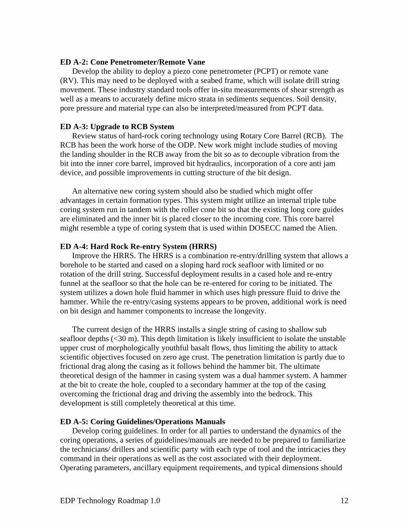
ED A-2: Cone Penetrometer/Remote Vane
Develop the ability to deploy a piezo cone penetrometer (PCPT) or remote vane (RV). This may need to be deployed with a seabed frame, which will isolate drill string movement. These industry standard tools offer in-situ measurements of shear strength as well as a means to accurately define micro strata in sediments sequences. Soil density, pore pressure and material type can also be interpreted/measured from PCPT data. ED A-3: Upgrade to RCB System
Review status of hard-rock coring technology using Rotary Core Barrel (RCB). The RCB has been the work horse of the ODP. New work might include studies of moving the landing shoulder in the RCB away from the bit so as to decouple vibration from the bit into the inner core barrel, improved bit hydraulics, incorporation of a core anti jam device, and possible improvements in cutting structure of the bit design.
An alternative new coring system should also be studied which might offer
advantages in certain formation types. This system might utilize an internal triple tube coring system run in tandem with the roller cone bit so that the existing long core guides are eliminated and the inner bit is placed closer to the incoming core. This core barrel might resemble a type of coring system that is used within DOSECC named the Alien.
ED A-4: Hard Rock Re-entry System (HRRS)
Improve the HRRS. The HRRS is a combination re-entry/drilling system that allows a borehole to be started and cased on a sloping hard rock seafloor with limited or no rotation of the drill string. Successful deployment results in a cased hole and re-entry funnel at the seafloor so that the hole can be re-entered for coring to be initiated. The system utilizes a down hole fluid hammer in which uses high pressure fluid to drive the hammer. While the re-entry/casing systems appears to be proven, additional work is need on bit design and hammer components to increase the longevity.
The current design of the HRRS installs a single string of casing to shallow sub
seafloor depths (<30 m). This depth limitation is likely insufficient to isolate the unstable upper crust of morphologically youthful basalt flows, thus limiting the ability to attack scientific objectives focused on zero age crust. The penetration limitation is partly due to frictional drag along the casing as it follows behind the hammer bit. The ultimate theoretical design of the hammer in casing system was a dual hammer system. A hammer at the bit to create the hole, coupled to a secondary hammer at the top of the casing overcoming the frictional drag and driving the assembly into the bedrock. This development is still completely theoretical at this time. ED A-5: Coring Guidelines/Operations Manuals
Develop coring guidelines. In order for all parties to understand the dynamics of the coring operations, a series of guidelines/manuals are needed to be prepared to familiarize the technicians/ drillers and scientific party with each type of tool and the intricacies they command in their operations as well as the cost associated with their deployment. Operating parameters, ancillary equipment requirements, and typical dimensions should
EDP Technology Roadmap 1.0 12

also be provided so that there is a clearer understanding of what is necessary and the parameters needed to run these tools. ED A-6 Diamond Coring System (Piggy Back)
A piggy back diamond system is routinely used in the offshore geotechnical industry to simulate onshore diamond coring techniques. This concept basically uses a secondary coring rig located in the rooster box above the top drive. A mining string is then lowered through the API string to advance a slim hole diamond coring string. ODP developed a similar version of this system called the Diamond Coring System (DCS) in the early 1990’s. It was abandoned due issues with the passive heave compensator (PHC) not being able to remove enough heave so that the secondary heave compensator on the DCS would function properly. It is unclear at this time whether this technology should be resurrected pending decision on the AHC/PHC. ED A-7: Large Diameter Diamond Coring Systems (ADCB)
Improve the ADCB. During ODP Leg 193, the ADCB was the coring tool of choice in intensely fractured, young lava flows. Whole round intervals, with insufficient integrity to hold together after removed from the core liner, were recovered intact using the ADCB. This tool is similar to core barrels used exclusively on many onshore applications. Based on thin kerf diamond technology, drilling with this system requires minimal weight on bit variation, thus is highly dependent on adequate heave compensation. Capturing shallow surface cores that reveal the tectonic history recorded in the uppermost section of exposed oceanic basement is likely to be one of the important contributions of this type of tool to the goals of the ISP. Further engineering developments might include operating this tool with a seabed frame for initial stabilization when spudding and/or with the HRRS as well as a better compensated drill string and bumper/thruster sub to bring this system to maturity for potential applications in hydrothermal systems and zero age crust.
ED A-8: Retractable Bit Technology
Develop retractable bit technology. This technology allows the cutting structure of the bit to be removed via a wire line or wire line tool. This device can save time by preventing the need to trip the string and save money by removing hardware expenses associated with re-entry schemes and mechanical bit release. By observing the bit each time the inner core barrel is pulled or when the performance is lacking, different cutting structures or completely new bits can be replaced to optimize drilling advancement or core recovery. While current bit longevity has improved, there still might be a requirement in the not so distant future where development of this concept might be very beneficial especially in deepwater or deep hole applications.
Retractable bit technology was pursued at ODP for several years while the Diamond
Coring System (DCS) was being developed as a piggyback coring system. Several versions were developed and tested. These include diamond bits from Russia, Australia and the USA as well as retractable tri-cone type bits based on the Russian technology that was developed during the deep hole Kola drilling project.
EDP Technology Roadmap 1.0 13
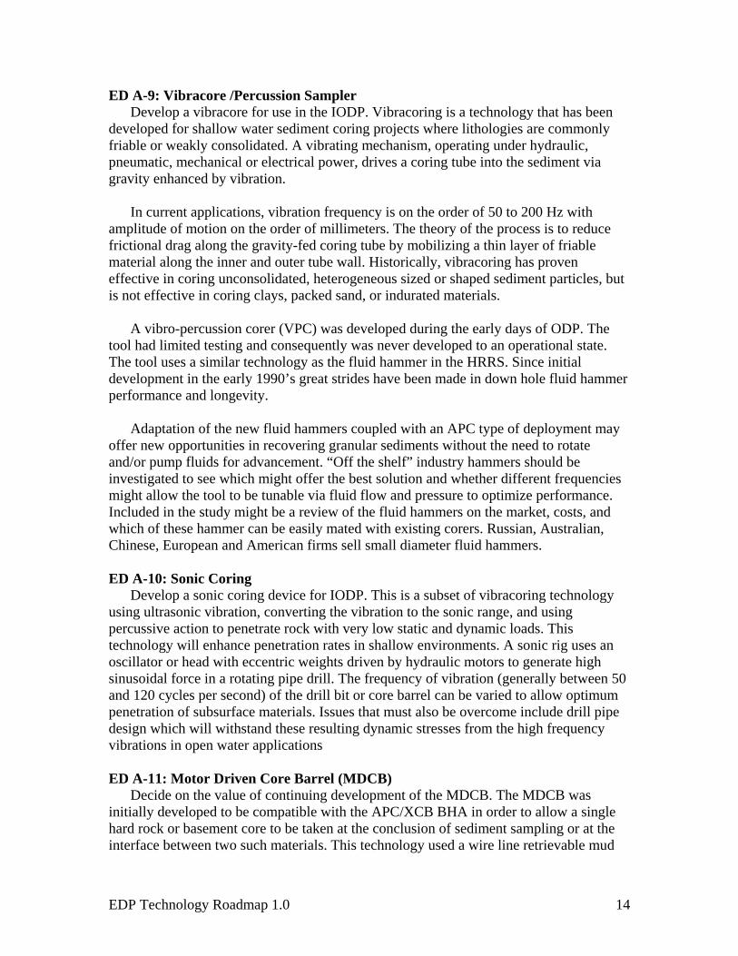
ED A-9: Vibracore /Percussion Sampler Develop a vibracore for use in the IODP. Vibracoring is a technology that has been
developed for shallow water sediment coring projects where lithologies are commonly friable or weakly consolidated. A vibrating mechanism, operating under hydraulic, pneumatic, mechanical or electrical power, drives a coring tube into the sediment via gravity enhanced by vibration.
In current applications, vibration frequency is on the order of 50 to 200 Hz with
amplitude of motion on the order of millimeters. The theory of the process is to reduce frictional drag along the gravity-fed coring tube by mobilizing a thin layer of friable material along the inner and outer tube wall. Historically, vibracoring has proven effective in coring unconsolidated, heterogeneous sized or shaped sediment particles, but is not effective in coring clays, packed sand, or indurated materials.
A vibro-percussion corer (VPC) was developed during the early days of ODP. The
tool had limited testing and consequently was never developed to an operational state. The tool uses a similar technology as the fluid hammer in the HRRS. Since initial development in the early 1990’s great strides have been made in down hole fluid hammer performance and longevity.
Adaptation of the new fluid hammers coupled with an APC type of deployment may
offer new opportunities in recovering granular sediments without the need to rotate and/or pump fluids for advancement. “Off the shelf” industry hammers should be investigated to see which might offer the best solution and whether different frequencies might allow the tool to be tunable via fluid flow and pressure to optimize performance. Included in the study might be a review of the fluid hammers on the market, costs, and which of these hammer can be easily mated with existing corers. Russian, Australian, Chinese, European and American firms sell small diameter fluid hammers. ED A-10: Sonic Coring
Develop a sonic coring device for IODP. This is a subset of vibracoring technology using ultrasonic vibration, converting the vibration to the sonic range, and using percussive action to penetrate rock with very low static and dynamic loads. This technology will enhance penetration rates in shallow environments. A sonic rig uses an oscillator or head with eccentric weights driven by hydraulic motors to generate high sinusoidal force in a rotating pipe drill. The frequency of vibration (generally between 50 and 120 cycles per second) of the drill bit or core barrel can be varied to allow optimum penetration of subsurface materials. Issues that must also be overcome include drill pipe design which will withstand these resulting dynamic stresses from the high frequency vibrations in open water applications ED A-11: Motor Driven Core Barrel (MDCB)
Decide on the value of continuing development of the MDCB. The MDCB was initially developed to be compatible with the APC/XCB BHA in order to allow a single hard rock or basement core to be taken at the conclusion of sediment sampling or at the interface between two such materials. This technology used a wire line retrievable mud
EDP Technology Roadmap 1.0 14
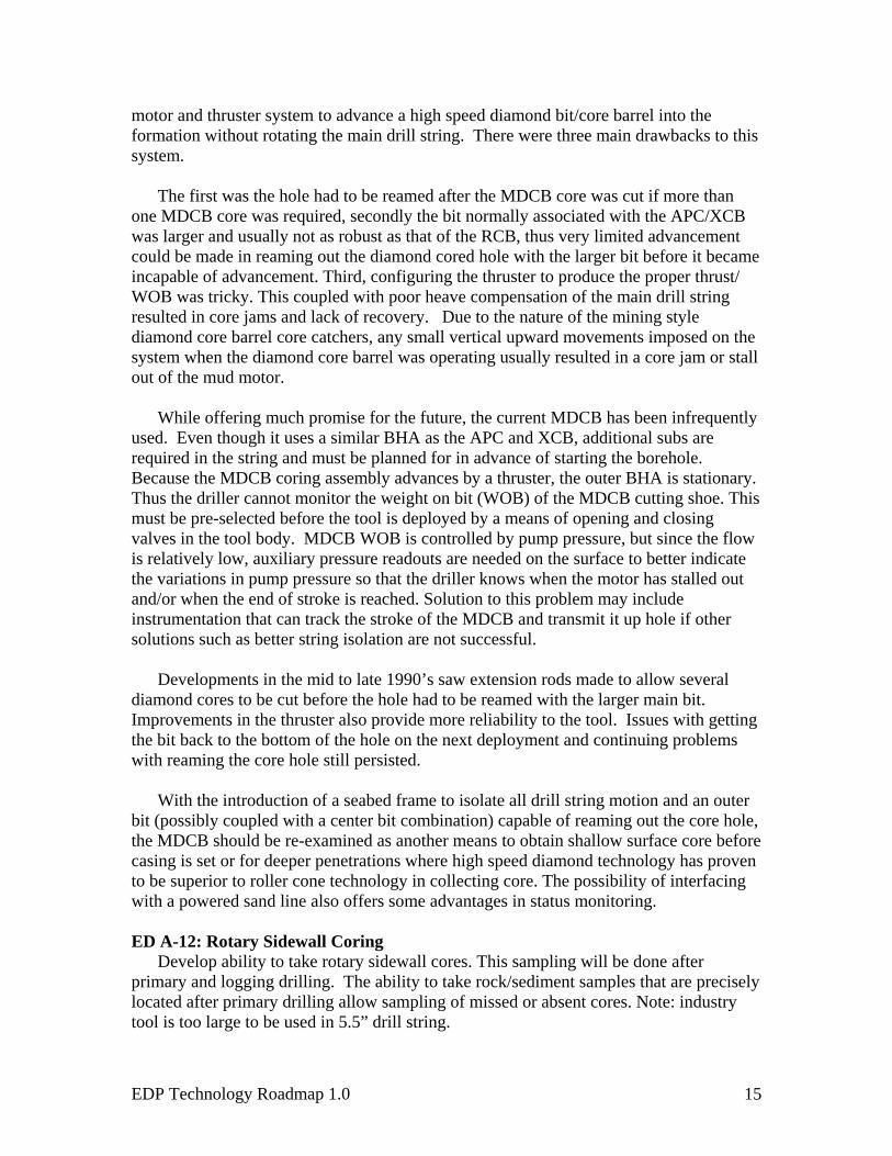
motor and thruster system to advance a high speed diamond bit/core barrel into the formation without rotating the main drill string. There were three main drawbacks to this system.
The first was the hole had to be reamed after the MDCB core was cut if more than
one MDCB core was required, secondly the bit normally associated with the APC/XCB was larger and usually not as robust as that of the RCB, thus very limited advancement could be made in reaming out the diamond cored hole with the larger bit before it became incapable of advancement. Third, configuring the thruster to produce the proper thrust/ WOB was tricky. This coupled with poor heave compensation of the main drill string resulted in core jams and lack of recovery. Due to the nature of the mining style diamond core barrel core catchers, any small vertical upward movements imposed on the system when the diamond core barrel was operating usually resulted in a core jam or stall out of the mud motor.
While offering much promise for the future, the current MDCB has been infrequently
used. Even though it uses a similar BHA as the APC and XCB, additional subs are required in the string and must be planned for in advance of starting the borehole. Because the MDCB coring assembly advances by a thruster, the outer BHA is stationary. Thus the driller cannot monitor the weight on bit (WOB) of the MDCB cutting shoe. This must be pre-selected before the tool is deployed by a means of opening and closing valves in the tool body. MDCB WOB is controlled by pump pressure, but since the flow is relatively low, auxiliary pressure readouts are needed on the surface to better indicate the variations in pump pressure so that the driller knows when the motor has stalled out and/or when the end of stroke is reached. Solution to this problem may include instrumentation that can track the stroke of the MDCB and transmit it up hole if other solutions such as better string isolation are not successful.
Developments in the mid to late 1990’s saw extension rods made to allow several diamond cores to be cut before the hole had to be reamed with the larger main bit. Improvements in the thruster also provide more reliability to the tool. Issues with getting the bit back to the bottom of the hole on the next deployment and continuing problems with reaming the core hole still persisted.
With the introduction of a seabed frame to isolate all drill string motion and an outer
bit (possibly coupled with a center bit combination) capable of reaming out the core hole, the MDCB should be re-examined as another means to obtain shallow surface core before casing is set or for deeper penetrations where high speed diamond technology has proven to be superior to roller cone technology in collecting core. The possibility of interfacing with a powered sand line also offers some advantages in status monitoring. ED A-12: Rotary Sidewall Coring
Develop ability to take rotary sidewall cores. This sampling will be done after primary and logging drilling. The ability to take rock/sediment samples that are precisely located after primary drilling allow sampling of missed or absent cores. Note: industry tool is too large to be used in 5.5” drill string.
EDP Technology Roadmap 1.0 15

ED A-13: Provide Core Orientation on standard coring tools.
Develop long-term pathway to be able to orient cores
a. Sediment core orientation: Current tensor tools (sediment core orientation apparatus) are no longer supported by the manufacturer. These have performed reliably for the last decade; however, maintenance and repair are problematic. Investigations into potential developments, performance enhancements, and internal support of the entire system are required. There are other systems available for diamond coring systems used in the mining industry which should be investigated to see whether they can be made compatible with existing tools.
b. Structural orientation of hard rock cores: The various components of a hard rock core orientation system (scribe, sonar target, sonic monitor, transducer, and rig instrumentation) are all necessary components of the overall system. Equipment used in the mining industry should be investigated to see if these units might be integrated before venturing into an internal development of components and testing prior to being placed into routine practice. ED A-14: Seabed Coring Devices (PROD)
Explore application of seabed coring device to capture first 100m of section. A number of shallow seabed coring devices have been developed which utilize high speed diamond coring techniques as employed in the mining/mineral exploration field. Many of the initial developments consisted of a 3 to 6m core barrel attached to a rotating head and supported within a seabed frame. Developments in the mid to late 1990’s saw the advent of several new generation seabed corers that had extended reach capabilities and were capable to obtaining deeper cores with the addition of rods behind the core barrel. Portable Remotely Operated Drill (PROD) was a second generation seabed drill that was capable to taking core to ~ 100m below the seafloor.
Continued development of this tool into the 2000’s has seen this device now become a routine tool used for geotechnical operations in collecting not only hard rock cores but CPT data and sediment samples as well. It is envisioned that if used in tandem with other IODP tools (HRRS/ ADCB/ MDCB) but on separate expeditions to collect the upper 100m of core, then IODP might NOT have to focus engineering developments on attempts to gather shallow core but could concentrate on using the more robust tools inside boreholes established by the HRRS. ED A-15: Jumbo Piston Corer
Develop ability to take long gravity piston cores. This will provide an effective means to sample the upper 30 m of sediment. This concept would limit or eliminate the number of triple APC cores because continuous core could be collected. Deployment could be concurrent with lowering the drill string and would be off axis from the side of the vessel.
EDP Technology Roadmap 1.0 16

ED A-16: Downhole Tools calibration and testing facility Create down hole tools calibration facility primarily on land and secondary on the
SODV and Chikyu, as required. Calibration of IODP downhole tools has not been a routine practice owing to the unique engineering requirements for each tool and lack of a commercial venture capable of providing routine calibration of these tools. The implementation of routine verification of tool performance will increase the tool reliability and data quality. A quality control program also needs to be incorporated into overall program.
ED A-17: Pressure Coring systems (PTCS, PCS, FPC, HRC, etc.) A recently completed hydrate sampling program utilizing a geotechnical drill ship has
reversed the poor performance of these tools in the past. Most of the recent industry work was performed with a seabed frame that isolated the drill string motion. The addition of a sea bed frame to the program may be needed to increase the recovery percentages with current third party tools. In addition, placement of the tool with respect to the outer bit, flow paths, cutting shoe design, size, and sealing mechanism, are still some of the items that need to be re-examined with regards to the IODP tools. Further enhancements might include additional temperature and pressure measurements while coring and de-gassing. Some of the new tools and associated equipment are only pressure rated to 250 bar and hence will need upgrading to achieve all the objectives associated with samples deeper in the sediment column and in deeper water.
ED A-18: Pressurized Sample transfer (autoclave)
Subseafloor microbiological investigations have been enhanced now that it is possible to maintain in situ pressures when transferring cores to laboratory apparatus. A few samples have been recovered at in situ conditions, held at those conditions, and manipulated in the laboratory without significantly altering the pressure. This recent development has allowed experiments to take place investigating the barophilic nature of microorganisms. These transfer systems are currently pressure limited to 250 bar. Consequently, further development is need to upgrade these systems to operate at higher pressures so that similar objectives can be achieved deeper in the sediment column and at greater water depths. ED A-19: New APC/XCB bits
Improvements to the APC/XCB bits might be made. However, bit longevity should be the key goal; ROP is not an issue. Wear is not an issue in coring soft sediments (bits typically survive a number of holes and legs). Roller cone bits have been the norm but PDC bits have also been tried and are sometimes preferred. PDC have demonstrated that they may cut faster and are less susceptible to balling but that real time savings is actually very small over the length of a 9.5 m core. Improvements can be made in the size, layout and waterway design. However, whether these improvements can justify the expense of PDC bits over the conventional roller cone has yet to be demonstrated. Cutters on PDC bits can be rotated and re-soldered to extend the life of these bits relative to roller cone bits. Modifications and/or attempts in upgrading the existing suite of bits may not command as much attentions as other issues already outlined in this document.
EDP Technology Roadmap 1.0 17

ED A-20: Common Bottom Hole Assembly (BHA) Current IODP practice uses the rotary core barrel (RCB) BHA for recovering core
samples in medium to hard formations and the APC/extended core barrel (XCB) BHA for soft to medium formations. The APC/XCB BHA can also be configured to run the motor-driven core barrel (MDCB) for use in hard, fractured rock, although it is seldom used. The four coring systems each have different core sizes (APC = 66 mm, XCB = 60 mm, MDCB = 57 mm, RCB = 59 mm).
Operational time required to round trip pipe when formations become too hard for
APC/XCB coring can take as long as a day in deep water. A common BHA will save operational time as well as long-term costs and reduce inventory. The practically of combining all coring systems into one BHA makes sense but may be rather difficult to physically achieve.
The primarily difficulty lies in the fact that one bit is not suitable for all formation
types. Possibly a better approach may be to investigate whether retractable bit technology may offer some options and the possible redesign of all existing tools to be compatible or continue to have two complete systems while developing some additional tools to help supplement the APC/XCB BHA. ED A-21: New RCB bits
RCB bits have been improved over the years. A number of designs are available depending upon the formation and abrasiveness being cored. It is doubtful that ROP could increase significantly unless some other driver was added. Another issue that IODP faces is that very few suppliers are interested in building a specialty bit with only small orders being placed. Presently IODP has only one roller cone bit supplier. For intermediate or softer formations materials an increased number of smaller cones bit which reduces the height of the core guides should be investigated. This improvement may increase core recovery between XCB and RCB. ED A-22: Upgrades to XCB system
Improve XCB. The XCB coring assembly operates very well in most cases. However, when coring through hard, dry clay, the face discharge waterways tend to plug, preventing circulation on the cutting face. The plugged waterways result in overheating which in turn destroys the cutting structure of these bits. This problem might be reduced by redesigning the coring shoe and providing automatic valves to maintain face discharge velocity, and/or powering the XCB shoe with a positive displacement motor independent of the XCB bit. ED A-23: Anti-Contamination System (Gel Core Barrel)
A system is required to prevent contamination of the core from circulated fluids through the application of an internal gel coating as the core is advanced into the inner barrel. Further investigation into land-based technologies should be thoroughly researched to modify this concept for offshore applications. This can provide longer core sections in a sterile environment.
EDP Technology Roadmap 1.0 18

ED A-24: New In-situ Sensors Understanding in-situ chemical conditions will require the development of new
devices. The possibility of implementation of new technologies such as Ion Sensitive Field Effect Transistor (ISFET), ion specific probes, and pH sensor should be investigated. ED A-25: Downhole Sonic Coring
Develop a downhole sonic coring device. This is a subset of vibracoring technology using ultrasonic vibration, converting the vibration to the sonic range, and using percussive action to penetrate rock with very low static and dynamic loads. A sonic rig uses an oscillator or head with eccentric weights driven by hydraulic motors to generate high sinusoidal force in a rotating pipe drill. The frequency of vibration (generally between 50 and 120 cycles per second) of the drill bit or core barrel can be varied to allow optimum penetration of subsurface materials. ED A-26: Fluid samplers, temperature and pressure measurement tools
High temperature water samplers deployed during ODP had a poor history of performance. These were all third party tools, rarely deployed, and commonly poorly maintained between deployments. Tools deployed for measuring high borehole/formation temperatures returned useful data, but owing to design were so lightweight that the driller could not determine if the tool was properly deployed, leading to eventual tool failure. Industry has developed hostile environment (max 200°C) temperature/pressure measurement and water sampling tools, but most have a minimum diameter too large to fit through the current IODP drill string. Development of a slim line equivalent, with elevated temperature (±350°C) is required for sampling fluids at high temperature environments. ED A-27: Transition Corers
Additional corers should be investigated to enhance the core recovery through transition zones. These samplers should be compatible with the existing APC/XCB BHA. Tools envisioned include an extended non-rotating sampler for sediments between the APC and XCB and a triple tube diamond core barrel similar to DOSECC’s Alien corer that would be deployed between the XCB and RCB initiation. One technique might be to use a triple tube design in which the inner bit is a very thin diamond kerf bit with the non-rotating inner tube being allowed to protrude in front of the both the outer bit and thin kerf diamond bit. The inner tube nose cone would more resemble an APC style shoe and allow the soil to be pushed past the nose cone into the inner barrel as the hole is advanced.
3.2.B Engineering Developments: Drilling/Vessel Infrastructure
ED B-1: Larger Diameter Pipe
Standard and specialty large diameter logging tools can be conveyed through a conduit with an inside diameter of ~5.5 inches. The purchase or rental of pipe should be considered. This might enable development of coring tools for obtaining large diameter cores.
EDP Technology Roadmap 1.0 19

ED B-2: ROV Guided Logging Tools
A Feasibility Study should be completed to evaluate the possibility of using an ROV to guide logging tools into an open borehole. This system is often used in industry today and there is need for an investigation as to how this operation is carried out. ED B-3: Heave Compensation
Poor heave compensation limits core recovery and lowers core quality. A robust, durable, drill string heave compensation system is critical to improved core recovery and quality of samples for the IODP. Improvements in this have already been made in industry with the use of heave compensated drilling platforms such as oil over air that was successfully used on Expedition 310 while piggyback drilling. Improved core recovery and core quality that was achieved during Expedition 310 should provide an impetus to advance this technology across IODP platforms.
On the riserless vessel and, if appropriate, the riser-vessel, it should be determined
whether procurement of a new or modified Active and/or Active/Passive Heave Compensation system will significantly improve drill string stabilization. Approaches to improve passive heave compensation performance might include modifications to cylinders, pistons, and seals. Improved active heave compensation hardware may also be required in terms of increasing the range of operable sea states and improving system reliability.
We emphasize the need for an integrated planning and development approach.
Ultimately, an integrated system (including active and/or passive heave, a pressure compensated bumper/thruster sub, and a sea bed frame utilizing a clamping system) when coupled with high quality rig and drill string instrumentation will enable the full suite of present and future down hole tools to work far more effectively in the full range of materials to be cored and tested. Computer-simulated drilling software should be utilized to enhance/configure the BHA design to reduce/eliminate vibrations when coring/drilling in different formations and water depths.
ED B-4: Heave compensation during advanced piston coring
This will reduce bit motion during piston coring. The current system requires shutting down heave compensation as the hydraulic piston core is charged and fired. During this process, the bit will respond to vertical ship motion, and ascertaining bit depth at the moment the piston fires has an error roughly equivalent to that of the bit travel. The result is poor absolute depth resolution and repeated or missing sediment sequences. A possible introduction of a seafloor frame to clamp onto BHA to isolate the heave may help elevate some of the problem described above. Thus further efforts should be investigated if this concept alone can solve the problem or whether design changes in the tool itself are required.
ED B-5: Seabed Frame
A Feasibility Study should be accomplished on the ability to deploy a seabed frame. A seabed frame is considered part of the drill string stabilization system.
EDP Technology Roadmap 1.0 20

Seabed frame technology, developed within the marine geotechnical industry over the
past ~30 years, has two major capabilities: (a) a seafloor mass that provides stability to the drillstring for improved deployment of tools; and (b) hydraulics at the seafloor that can be used for controlled in-situ testing and some coring applications. This capability, possibly supported with a deep-water ROV or acoustically activated clamping system, would expand the non-riser capability to meet scientific objectives that require the need for:
(a) Recovery of sand on continental margins and deep water fan systems; (b) Recovery of corals in shallow water environments; (c) Deployment of in situ tools for the measurement of pore pressure, resistivity,
and temperature as well as gamma ray density, acoustic velocity and other “wireline” logging measurements in the upper 100 mbsf and in unstable borehole formations; and
(d) Deployment of specialty tools for the measurement of in situ stress (e.g. packers).
As early as 1998, the scientific community identified the need for a “seabed frame” to
meet the IODP scientific goals with the new IODP non-riser vessel (CDC, 2000). The May 2004 Downhole Tool Workshop participants re-affirmed this need (http://www.usssp-iodp.org/PDFs/DHT_Workshop_Final.pdf). Implementation of such seafloor devices may enhance recovery, allow the MDCB to initialize spudding on hard rock holes, and improve core recovery. Being able to immobilize the drill string may also improve the recovery of certain PCS-type tools.
ED B-6: Pressure Compensated Bumper/Thruster Sub
A feasibility study should be pursued on the development of a pressure-compensated Bumper/Thruster Sub to remove residual amounts of drill string motion as a means to improve core quality and quantity
Bumper subs were used in the early days of offshore drilling to help keep the bit on
the bottom of the hole due to the vertical movement of the pipe from ship motion. A bumper sub is nothing more than a drill collar sized tool that incorporates a sliding sleeve.
Due to the length and consequently the weight of the drill string typically deployed by
the USIO program, even with the most advanced heave compensation system, it is doubtful that all vertical movement can be eliminated by a single device whether it is an active or passive heave compensator. Thus, there is a need to investigate whether a mechanical and/or pressure activated sub can be developed to complement whatever primary heave compensation system is selected.
A first generation shock sub was developed for the ADCB in the late 1990’s at ODP.
The system was developed to reduce costs by extending bit life, increasing ROP and reducing drill string failures. The tool extends bit life by reducing impact loading on the bit. ROP is increased by reducing BHA vibration allowing optimum rotary speeds to be
EDP Technology Roadmap 1.0 21

used. The tool was designed to operate effectively under a combination of WOB, bit pressure drop, mud weight, or hole depth. While this tool was not designed to specifically maintain a constant WOB, it does provide some damping before the load eventually finds it way to the bit.
A possible first step in any further development of such tools would be to test the
existing tool in a side by side comparison while using the ADCB and the bit motion accelerometer tool developed by Lamont. Knowledge learned from such a test program would be invaluable before approaching a vendor to develop a larger version that would be of the same size as the current IODP BHA design. Reducing micro WOB fluctuations which can be offered by such a tool may be a giant step to better understand existing tools as well as improve core recovery. ED B-7: Rig Instrumentation System
The RIS is an important tool to achieve drill string compensation. It is essential for effective drilling operations and in many situations a key component for achieving scientific objectives by providing drilling operations measurements. Rig instrumentation data should be preserved as a part of the scientific data.
The primary technology advancements in a rig instrumentation system will be increased sampling rate, integration of measurement while drilling applications, and integration of operational data into the arsenal of tools used to interpret formation characteristics. Potential improvements include accurate, continuous position recording and measuring tidal influences as they apply to true depth estimates. ED B-8: Improved Automatic Driller
A recent development in industry is to use data from the RIS (Rig Instrumentation System) to automate some of the drilling process. The simplest systems attempt to modulate weight on bit variations and thus improve coring efficiency. ED B-9: Drilling parameter acquisition while coring
Complete the technology development and routinely deploy the down-hole sensor sub (DSS) and remote memory module (RMM). These tools have been or are scheduled for bench testing. DSS is incorporated as part of the BHA and the DSS and RMM both store data and the RMM returns incremental data sets via coring line after each core barrel run. These instruments record weight on bit, torque on bit, annular pressure, and temperature. Down-hole pressure can be used to estimate whether there is gas or sand flow within the annulus. Knowledge of weight on bit, and torque on bit can be used to modify drilling procedures to optimize coring conditions.
ED B-10 Real time drilling parameter acquisition while coring
Transmit from down-hole sensor sub (DSS) in real time the drilling dynamics data to the surface like weight on bit, torque on bit, annular pressure and temperature. Most probable technique will be mud-pulsed telemetry to the surface. A subset of the same data acquired by the logging-while-coring system can be continuously transmitted to the
EDP Technology Roadmap 1.0 22

rig floor. The real-time knowledge of weight on bit, and torque on bit can be used to modify drilling procedures to further optimize coring conditions.
Mud pulse telemetry is a method widely used in industry to transmit drilling data
from the bit to the rig floor. This type of system is commercially available and historically reliable, with data transmission rates on the order of 12 bits per second. The digital data stream from the sensors is compressed and transmitted to the surface via pressure pulses, where each pulse is one bit of a data stream. The pressure wave travels through the pipe and is detected by sensors at the rig floor. The sensor data is decoded and displayed as down hole diagnostic parameters. If displayed in real time, the driller can make active adjustments to drilling parameters and optimize drilling stability, thus potentially improving core recovery and quality. ED B-11 Formation logging while coring
Once the real-time logging data acquisition system has been developed and qualified in field tests, a subsequent desired development is inclusion of formation evaluation logging sensors (i.e., gamma radioactivity, resistivity, bulk density). These data can accompany real-time drilling parameter data transmission. ED B-12: Radio Frequency ID Chip Implant in Drill Pipe
Current practice for measuring the depth of the bit below rig floor is to physically measure (strap) the length of each joint of pipe and to tally these individual lengths as each joint or stand of pipe is added. This process can be automated via the use of Radio Frequency Identification Devices (RFIDs) embedded in the tool joint of each length of pipe, pre-coded with several types of information including length. As the tool joint passes a sensor on the rig floor, the length is uploaded to an automated accounting system, thus eliminating potential operator error in pipe length determination. Additional data stored on RFID tags can potentially be used to prolong pipe utility through preventative maintenance programs.
ED B-13: Intellipipe
Several engineering developments can be applied to advancements with in situ formation characterization. These range from direct application or adaptation of off the shelf industry technology, to complete developments for unique operational environment. Intellipipe is a real time, high speed data transmission system that allows deployment of multiple sensors at or near the bit to provide drilling and formation parameter measurements (the pipe is essentially wired). In current designs the data transmission system runs inside the pipe and compatibility with coring operations is not well developed. In addition, current pipe acquisition is on a lease only basis from the sole source vendor, thus cost could be a significant issue.
ED B-14: Electric/optical wireline
A technology development that could provide enhanced data acquisition functionality while saving operational time is development of a powered fiber-optic augmented coring line (essentially combining the logging and coring lines). While it is not likely this line could be used on a routine basis (owing to excessive wear of an expensive cable), for
EDP Technology Roadmap 1.0 23

specific applications power could be delivered to down-hole coring or measurement tools without special rigging. This could also potentially directly communicate with observatories via wet connectors and/or active overshot connectors. ED B-15: Directional Coring
There are multiple applications of the industry-proven directional drilling technology to scientific ocean coring. Successive hole deviations in deep penetrations can save operational time and provide a three-dimensional perspective to the more routine single-dimensional view developed from a one core. Horizontal drilling may be required to develop an understanding of seafloor hydrothermal systems, and controlled directional drilling is directly applicable to characterizing three-dimensional structure and investigating tectonic problems. This technological development requires application and adaptation of proven industry tools and practices incorporate continuous coring. Magnetic overprint
Degaussing the drill string via an AF coil mounted beneath the rig floor was attempted during DSDP. The coil was destroyed fairly quickly during operations and the analysts interpreted that inasmuch as the pipe was exposed to additional stresses on each deployment this was probably a fruitless endeavor.
Replacing drill string components with nonmagnetic materials has been tested on
several expeditions. Basically the important characteristic of materials used for this purpose is magnetic permeability. Magnetic permeability of some materials is listed below.
Magnetic permeability and yield strength of materials
Material Magnetic permeability Approximate yield strength Cost/cost of iron titanium 1.00005 950 MPa 2500 monel 1.002 100-150 MPa 4000 stainless steel 1.008 500-600 MPa 700 iron 150 300-500 MPa 1 silicon iron (4% Si) 500 no data no data
The most radical solution could be to replace the entire drill string and all components with nonmagnetic material. It is not likely a nonmagnetic drill string is readily available. Any search for nonmagnetic or low magnetic permeability materials yields only a few results. These include titanium, monel (a compound of predominantly nickel with copper, iron, and manganese), and some varieties of stainless steel. Costs of raw metal/alloys relative to iron are listed in Table 1. Considering an iron drill string will cost in excess of $1 million, none of the other nonmagnetic components are even feasible in terms of cost, even if an interested vendor could be located.
Recent studies have concluded that restricting the amount of time the core is in
contact with the core barrel, as well as employing core capture components fabricated from nonmagnetic materials significantly reduces the strength of the viscous remanent
EDP Technology Roadmap 1.0 24
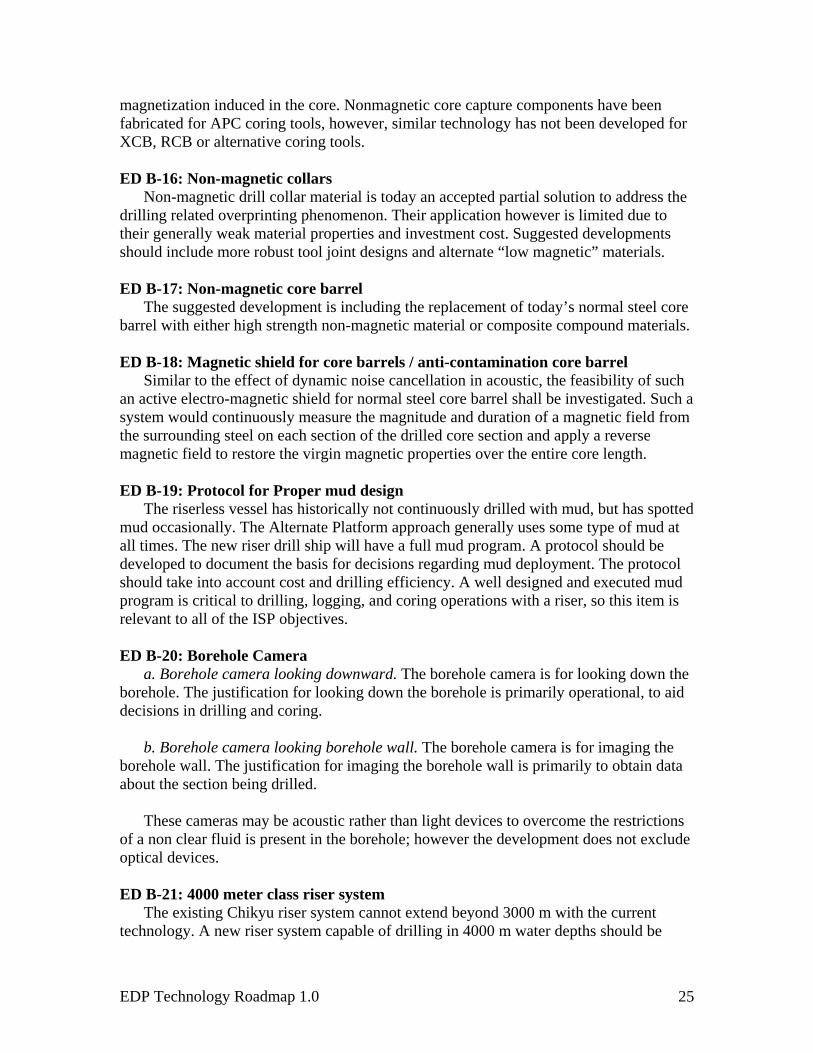
magnetization induced in the core. Nonmagnetic core capture components have been fabricated for APC coring tools, however, similar technology has not been developed for XCB, RCB or alternative coring tools.
ED B-16: Non-magnetic collars
Non-magnetic drill collar material is today an accepted partial solution to address the drilling related overprinting phenomenon. Their application however is limited due to their generally weak material properties and investment cost. Suggested developments should include more robust tool joint designs and alternate “low magnetic” materials. ED B-17: Non-magnetic core barrel
The suggested development is including the replacement of today’s normal steel core barrel with either high strength non-magnetic material or composite compound materials. ED B-18: Magnetic shield for core barrels / anti-contamination core barrel
Similar to the effect of dynamic noise cancellation in acoustic, the feasibility of such an active electro-magnetic shield for normal steel core barrel shall be investigated. Such a system would continuously measure the magnitude and duration of a magnetic field from the surrounding steel on each section of the drilled core section and apply a reverse magnetic field to restore the virgin magnetic properties over the entire core length. ED B-19: Protocol for Proper mud design
The riserless vessel has historically not continuously drilled with mud, but has spotted mud occasionally. The Alternate Platform approach generally uses some type of mud at all times. The new riser drill ship will have a full mud program. A protocol should be developed to document the basis for decisions regarding mud deployment. The protocol should take into account cost and drilling efficiency. A well designed and executed mud program is critical to drilling, logging, and coring operations with a riser, so this item is relevant to all of the ISP objectives.
ED B-20: Borehole Camera
a. Borehole camera looking downward. The borehole camera is for looking down the borehole. The justification for looking down the borehole is primarily operational, to aid decisions in drilling and coring.
b. Borehole camera looking borehole wall. The borehole camera is for imaging the
borehole wall. The justification for imaging the borehole wall is primarily to obtain data about the section being drilled.
These cameras may be acoustic rather than light devices to overcome the restrictions of a non clear fluid is present in the borehole; however the development does not exclude optical devices. ED B-21: 4000 meter class riser system
The existing Chikyu riser system cannot extend beyond 3000 m with the current technology. A new riser system capable of drilling in 4000 m water depths should be
EDP Technology Roadmap 1.0 25
developed. Several of the ISP objectives will require wells in water depths exceeding 2500m. ED B-22: 4,000 meter class BOP
The current subsea blowout preventers on the Chikyu are driven by hydraulic force powered by the surface vessel and subsea nitrogen accumulators. In water depths of 4,000 meters, these accumulators will no longer work well due to changed characteristics of the extremely compressed nitrogen, and the hydraulic pressure supplied from the surface accumulator greatly decreases due to pressure loss through longer hydraulic line between surface accumulators and blowout preventers. To drill in water depths of up to 4000m, a new blowout preventer based on a different technology will be required to accompany the new riser system described above. ED B-23: Reduce Current Force on Chikyu Riser
While drilling under normal conditions, mean angles at both of upper flex riser joint and lower one have to be maintained within 2 degrees. The stronger current force might cause the larger angles of both flex joints beyond its tolerable range. Also, larger VIV (vortex induced vibration) on the riser under strong current is recently indicated to cause the fatigue damage. In order to prevent these problems, it is necessary to reduce the drag coefficient of the riser pipe and the vortex around the pipe. Installing fairings onto the riser is effective for reduction of the current force. Optimal shape and arrangement of fairings is needed to be studied. ED B-24: Improve Dynamic Positioning Systems
In order to increase operability of CHIKYU and other DP vessels under severe sea and current conditions, more precise and efficient control for position keeping will be required. Based on investigating the present abilities of the Chikyu, the control method of DPS, the Riser Angle Control and Power Management Systems should be improved. The justification will come from item 13 in the Technology Plan, an investigation of expected sea states and currents in anticipated drilling locations. ED B-25: Improve Expandable Casing System:
Develop expandable casing for ultra deep, high temperature, high-pressure H2S environments. The expandable casing technology developed by the petroleum industry may not meet the hostile environments that will be drilled during the IODP. Having an expandable casing option for these conditions will increase the probability of success in drilling wells in these environments. ED B-26: Develop cement slurry for deep drilling.
When sealing of fluid pressure adjacent to the set casing is required, it will be necessary to develop cementing technology that is designed for severe environmental conditions. The cement slurry used in an ultra deep environment must withstand high temperature/pressure. In addition, temperature in the hole may vary greatly because of variable circulation of drilling mud. The casing will experience the expansion/shrinkage which may be detrimental to the cement seal. The cement slurry must be designed with flexibility to avoid destruction of its seal to the casing.
EDP Technology Roadmap 1.0 26

ED B-27: Drill pipe for ultra deep ocean drilling
Chikyu is currently equipped with drill pipe that is designed to drill 10,000m below sea level. To drill through 21st Century Mohole, a 12,000m length drill string is required. The practical maximum drilling depth is primarily constrained by the strength-weight ratio of the drill string. In order to reach 12,000m depth below sea level, it is necessary to develop a high strength and light weight drill pipe that is not degraded by high temperature and H2S. ED B-28: High temperature High Pressure Vertical Drilling System (VDS)
A non-vertical hole may be induced when the drilling is continued without controlling the trajectory in structurally complex, high dip or high stress formation. At shallow depth, such deviation from vertical does not affect the drilling significantly, but in the ultra deep hole, the deviation may bring increase of drilling torque, instability of bore hole, damage to casing and other problems. We must not forget that a great effort was made to drill nearly vertical hole for scientific objectives in KTB project. Therefore, it is necessary to develop a vertical drilling system (VDS) for the high pressure/temperature environment. This technology is closely related to LWD/MWD technology and Downhole Motor technology, and automatic control of hole trajectory by applying rotary steerable technology used by oil industry. The key is to improve this technology to science objectives.
In addition, the method to drill an inclined hole intentionally while controlling its
direction and inclination using advanced VDS is thought to be effective to reduce borehole instability caused by large stress differences over vertical intervals of a hole. It is expected that this technology might be necessary for penetrating the Seismogenic Zone. ED B-29: Mud circulation drilling system over 3,000-m water depth
The limit of water depth for current riser drilling system to be applied is approximately 3,000m. Parallel to the efforts to improve current riser drilling riser and BOP, it is important to consider a new system like flexible riser and dual-gradient drilling system (seafloor pump, SWD:Subsea Mudlift Drilling, etc.). The best approach should be taken through the comparison of pros and cons between the current riser and the new system. ED B-30: Freestanding, remotely operated deepwater shallow hole coring system
There is a gap in core recovery for science objectives while coring in deepwater conditions with riser and non riser vessels. In some settings, core recovery is low to nonexistent from the first 50-100 meters below seafloor. Recently new remote drills have been brought onto the market that can recover this type of core, but as yet none can operate in water depths of more than 3000m. A feasibility study should be made into the existing remote drills to determine whether any can be up graded to work in depth in excess of 3000m with core recovery depths of 50-100m.
EDP Technology Roadmap 1.0 27

ED B-31: Drill pipe conveyed deep water, shallow hole coring tools Prototypes of coring tools that are designed to recover shallow cores from lithified
sediment or basement exposures at the seafloor have proved promising but require engineering development. Mud motor operated systems require bit design to improve core recovery and internal component development to reduce maintenance and improve performance. In addition, the driller cannot monitor the weight on bit (WOB) of the MDCB cutting shoe. MDCB WOB is controlled by pump pressure, but because the flow is relatively low variations in pump pressure do not clearly indicate WOB or even motor stalling. The solution to this problem may require instrumentation that can track the stroke of the MDBC and transmit the information uphole. In its current design, the reduced strength of the ADCB BHA precludes initiating a borehole with this system. Capturing shallow surface cores that reveal the tectonic history recorded in the uppermost section of exposed oceanic basement is likely to be one of the greatest contributions of a tool of this theme of the ISP. Further engineering developments in drill collar design and deployment protocols are required to bring this system to maturity for potential applications in hydrothermal systems and zero-age crust. 3.2.C Engineering Developments: Borehole Infrastructure
ED C-1: High temperature electronics and sensors
Deep drilling targets, such as the Nankai Trough, and shallow, high temperature hydrothermal systems at spreading ridges have a critical need for the development of high temperature electronics and sensor systems. Longer-term science objectives for drilling the Moho will require even higher temperature tolerance and reliability not presently available commercially or from academic laboratories. Substantial efforts are underway commercially and in academic labs for creating new types of temperature sensors and signal conditioning electronics for geothermal well applications. Collaboration with these groups on specific scientific applications on IODP drilling legs would be the most beneficial approach for obtaining access to these emerging technologies. Joint development partnerships funded specifically for drilling targets would also be a suitable approach.
ED C-2: Temperature tolerant muds/drilling bits etc.
The geothermal drilling industry has developed methods and materials appropriate for drilling hot dry rock and hot geothermal fluids. Collaboration with this industry and development of joint development partnerships would be the most beneficial approaches to identifying the technological solutions to drilling into hot, wet rocks.
In current technology, maximum temperature limits of water-based mud is 240-260
degrees Celsius. In holes drilled by Chikyu, the bottom hole temperature are expected to reach ~300 degrees Celsius. Development of the drilling mud systems that can be applied to these drilling targets is clearly necessary. Operations in other high temperature environments will also require modified mud systems and drilling bits to achieve depth targets.
EDP Technology Roadmap 1.0 28

ED C-3: Improved cementing techniques for high temperature applications The installation of long-term borehole monitoring systems and isolation of hydrologic
zones in boreholes located in high temperature environments will require improvements to cement composition and emplacement techniques. Much can be learned from the geothermal industry, and the hydrocarbon industry regarding existing technologies. ED C-4: Corrosion tolerance
Long-term deployments and deployments in chemically hostile environments will require use of more exotic materials for pressure cases, sensor probes, etc. Much can be gained from the geothermal well and hydrocarbon industry practices and technologies to procure devices that can tolerate corrosion. ED C-5: Packer-like technology development
Demand for reliable hydraulic isolation of multiple horizons has increased in the IODP. Packer technology has limitations, especially reliability and long-term integrity of the borehole seals. There is no established method for monitoring the integrity of borehole packers and no protocol for what to do if a seal is lost. Because there is high demand for CORK technology in the drilling proposals under consideration or scheduled, an assessment of packer technology is dictated. Development of alternative technologies or solutions for multiple isolation is needed.
ED C-6: Improved cementing techniques for hydrologic isolation
Improved casing-to-formation cementing techniques are required to provide hydrologic isolation (hydrology experiments and fluid sampling) and mechanical coupling with formations (seismology experiments). Improved cementing techniques may obviate the need for packers in some instances.
ED C-7: Reliable wellhead seals and hanger seals
Although this appears to be an incremental improvement, successful long-term deployment of any borehole experiment (not just CORKs) relies on creating and maintaining the integrity of seals between each casing string run into a borehole. At present reliable (acceptable?) wellhead seals have not been designed or installed. A Feasibility/Design Study is needed to assess present sealing techniques, and to investigate design improvements. The design improvements may radically change the topside configuration of the borehole hangers, thus this study has the potential to expand beyond its initial focus in order to achieve the desired technological outcome.
ED C-8: Electric, optical fiber and fluid feed-throughs at wellheads
The desire to install long-term borehole monitoring systems and to conduct in situ borehole experiments requires that electrical cables, optical fibers, and fluid tubing pass through the wellheads of boreholes. The feed-through strategy must be compatible with existing shipboard deployment procedures and casing hanger geometries. The topside connections at the wellhead must be ROV-compatible and easily accessed for making and breaking connections. One challenge is accommodating the increasing number of desired feed-through connections and their types. For example, the BOP used for riser drilling presently is limited to a maximum of 8 feed-throughs, but each feed-through could
EDP Technology Roadmap 1.0 29

accommodate multiple conductor bundles. This limitation will constrain the topology of downhole monitoring systems. These methods need to be developed for all 3 IODP platforms.
ED C-9: Identification and tracking of drilling contaminants – also methods for minimizing contamination
Advances in geochemical and microbiological measurements depend on obtaining pristine samples, uncontaminated by drilling fluids and materials from other horizons in the borehole. Some methods have already been employed during the ODP (e.g., fluorescent beads in a bag), however there is need for further development of these tracer techniques, and means for identifying chemical or biochemical signals indicative of contamination. Methods for minimizing contamination are in their infancy, however commercial products, such as the gel coating system (Baker-Hughes) offer potential solutions to drilling fluid contamination. Investigation of this method and others is warranted.
ED C-10: Casing boreholes through fault zones
A major drilling target for the Chikyu is the Nankai Trough. Drilling through and successfully casing an active thrust fault for long-term monitoring has not been accomplished and is integral to the scientific objectives of this major effort. Lessons from the ICDP SAFOD project indicate the difficulty of accomplishing this task, however offer some guidance for potential solutions. We need good strategies for drilling the hole, casing, and cementing. Success with these operations requires knowing in real-time an accurate state of stress and fluid pressure conditions in the zone spanning active deformation. Adapt methods from academic research to measure state of stress.
ED C-11: Physical coupling to borehole and noise reduction for acoustic instruments
Further development of techniques for coupling seismic and other geophysical sensor to formations is needed. The measurement of mechanical noise in boreholes to identify their sources, strength, and frequency range is needed to help mitigate its effects on subsequent sensor installations in other boreholes. Techniques need to be developed for reducing noise, such as isolation of sensors from casing strings and other noise sources (e.g., pumps, borehole convection, and seafloor infrastructure).
ED C-12: Thermal measurements in boreholes – thermally-neutral materials/completions
Measurement of accurate temperatures and thermal gradients in boreholes are affected by the thermal properties of the borehole completion (steel pipe is a much better conductor than wet sediment). There is a need to identify appropriate materials and thermal isolation strategies to reduce thermal anomalies affecting temperature measurements in boreholes.
EDP Technology Roadmap 1.0 30

ED C-13: Sampling techniques for microbiology experiments and in situ incubation systems
There is a need to develop more versatile sampling techniques for microbiological sampling to get beyond the contamination halo of a borehole. In some cases, the return of microbiological samples to the surface is not suitable, and in situ incubation may be the best means for properly identifying and describing the community composition and the physiology of these organisms. Some samples of various types (enrichment cultures, stained samples, or archived materials) could be returned to the surface after completion of the incubation experiments. In other cases, recovery of microbiological samples at in situ conditions will be desired. Shipboard culture systems operated at in situ conditions will be needed receive these samples and to study them. ED C-14: Development of low power sensors – temperature, pressure, electromagnetic, seismic, and chemical measurements
This is represents a broad spectrum of needs. Each type of sensor (T, P, E, S, and C) needs development that matches science requirements. Low power consumption is an essential technological development for any long-term borehole monitoring system. The development of novel optical-based sensing systems (DTS, or optical-seismic sensors) that do not require downhole electric circuits is one approach to achieving substantial reduction in overall power requirements. ED C-15: Development of methods for cross-hole hydrologic experiments
Methods need to be developed for conducting cross-hole hydrologic experiments to determine geohydrologic properties (e.g., permeability, storativity), similar to those that are routinely conducted on land by commercial consulting companies. Monitoring techniques, sensors, inert tracers, continuous chemical measurements and sensor deployment strategies in the observation borehole are needed to optimize the outcome of these experiments. The development of borehole pumping systems or means of propagating a pressure disturbance in a borehole are also needed. ED C-16: Systems reliability for LTMS
High reliability systems are required for successful deployment and operation of long-term monitoring systems. Manufacturing and test procedures, strategies for redundancy and fault tolerance, maintenance procedures and strategies are critical elements of maintaining high-level systems reliability. Much of these requirements are mature methods in major industries, such as the telecommunications industry (including submarine telecom cabling), and are readily available and can be easily adapted for engineered systems on and below the seafloor. ED C-17: ROV-serviceable wellheads and submarine cable connections
With the establishment of long-term monitoring programs for boreholes, periodic maintenance will be required to change batteries, collect samples, change experimental gear, make submarine cable connections, and to repair the monitoring systems. The wellheads initially deployed by the drillships will need to be design to accommodate ROV servicing. The ROV manipulators will have to reach the interior portion of the
EDP Technology Roadmap 1.0 31

wellheads, be able to lift and exchange instrument packages, and to plug and unplug electrical and telemetry cables, and fluid lines at the wellhead. A test borehole facility could be used for training ROV-pilots and testing procedures. This would minimize operational costs and improve efficiency and reliability of actual deployments. There is also a need for standardization of interfaces between wellheads and ROVs. ED C-18: Efficient power systems, including distribution
Depending on the sophistication and planned lifetime for long-term monitoring systems in boreholes, efficient power systems, including power supplies, cables, connectors, and control/monitoring systems will be required to support these monitoring systems. Fault tolerance, ground fault sensing, resettable thermal breakers for isolating faulty equipment, development of observatory control systems for power load management and engineering data subsystems are necessary components of an efficient and effective power system.
ED C-19: Design standards for electrical, communications, mechanical, and fluid systems
Uniform standards need to be established for electrical, communications, mechanical, and fluid systems in borehole observatories, in coordination with observatory initiatives in the US, Japan, and Europe. Standards will enable compatibility, integration, and inter-operability between different subsystems developed independently by a variety of investigators on a more cost-effective basis. This will also reduces errors and increase reliability.
ED C-20: Deployment procedures/soft-landing
Placement of instrument strings, CORKs, casing, seismometers, and complex borehole instrument systems into boreholes will require improved precision in depth placement and tolerance for ship heave. Reduction in ship heave would be the most beneficial technological development, however, other strategies to dampen ship motion could be developed and employed.
ED C-21: Managing borehole experiments
Effective management of long-term borehole experiments is essential for continued success of these systems and for the provision of opportunities for multiple investigators to participate in the scientific experiments. Data policies need to be established. Procedures for instrument qualification procedures need to be established and enforced before instrument deployment. One way to qualify instruments is to test them at a borehole test facility. ED C-22: Data systems and telemetry in boreholes and on the seabed
Reliable data systems and telemetry are required for the operation of long-term borehole monitoring systems. These systems need to meet the distance/cable length and power requirements of the experiments. Metadata for the suite of borehole instruments is necessary for proper borehole management and data archiving. The telemetry system will need a system status and reporting system to monitor the engineered parts of the system.
EDP Technology Roadmap 1.0 32
ED C-23: Compatibility with non-IODP platforms An understanding of non-IODP platform capabilities and how to interface these
systems with borehole experiments and long-term borehole monitoring systems will be necessary to optimize maintenance and recovery/re-installation of borehole observatory instruments. ED C-24: Borehole re-entry and servicing systems
Techniques and infrastructure will be required to allow the recovery and re-installation of borehole instruments in order to maintain long-term observatories (repair and replace) and re-use existing ODP/DSDP boreholes. This may include re-designing wellhead templates and modifying operational procedures shipboard. 3.3: Process of Engineering Development
EDP has put a great deal of effort into developing a process to nurture, evaluate, and advance technology developments within IODP. We summarize several of the significant processes we have adopted
#1) 4 Stage Development Process
Any proposed technology development should follow a 4 step process that includes the following stages: Concept, Design, Fabrication, Implementation. Every project should pass through each of these stages. Many projects many enter the Concept phase, but only a few may make the stage of fabrication.
EDP recommends that a review is performed at the end of each of the 4 stages. EDP is not the reviewer, but would like to see a summary of the review. EDP would give advice at the concept stage, and by exception give advice later in project life.
#2) Open Proposal Process
3 avenues for submission of EDP proposals to allow effective implementation of the E.D. goals of the IODP.
a. IO’s may submit proposals to IODP-MI based on internal needs assessment. b. Interested parties submit proposals to IODP-MI in response to RFPs issued by IODP-MI. c. 3rd Parties submit unsolicited proposals to IODP-MI.
Proposals submitted to IODP-MI. Must satisfy the requirements of Stage 1 (Concept).
Proposals will be identified as addressing one or more of the remaining 3 stages of engineering development: Design, Fabrication, or Implementation.
#3) EDP Review
EDP will review all Concept proposals. EDP will evaluate the proposal relative to the EDP Technology Roadmap or relative to achieving the goals of the ISP if the proposed development is not yet addressed in the Roadmap. The evaluation will assess how well the proposal meets established ED needs and provide a recommended course of action to SPC. In the event a Proposal does not address an established need, it will be evaluated with regards to its benefit to overall IODP-MI needs.
EDP Technology Roadmap 1.0 33

References
Integrated Ocean Drilling Program, 2003, IODP Initial Science Plan 2003-2013: Earth, Oceans and Life, Integrated Ocean Drilling Program.
EDP Technology Roadmap 1.0 34

Technology Roadmap - Engineeering Development Projects (draft)Engineering Developments-Group A -Sampling, Logging, and Coring
this is specific device being developed This is the more general category
ED # Engineering Development Requirements Science Goal ISP Technology Challenges AvailabilityDescription of develoment What needs to be accomplished? How does it fit with ISP? Refer
to Table 1Refer to Table 2 Existing Technology (i.e.
buy off shelf) (E), Modification (M), Innovation (I)
1 Thin-walled, geotechnical core sampler Acquire minimally disturbed geotechnical cores all 3,5,7,8,11 I E2 Cone Penetrometer/Remote Vane Better characterization of in-situ strength and material
propertiesall 2,5,8,11 I
3 Upgrade to RCB system Hard rock coring all 3,11 M4 Hard rock re-entry system (HRRS) Hard rock spudding all 9.11 M5 Coring guidelines/operations manuals Reliable operation of tools all 3,11,7,8 I6 Diamond coring systems (Piggyback) Improved core quality and core percentage all 3,11 (8) M7 Large Diameter Diamond Coring Systems (ADCB) Improved core quality and core percentage all 3,11 M
8 Retractable Bit Technology Improve coring efficiency in unstabe formations all 3,9,11,2 I9 Vibracore/Percussion Sampler High percentage core recovery. Shallow sampling (rubble,
unconsolidate sand)all 3,11 M
10 Sonic Coring Faster rate of penetration in shallow conditions for MSP all 3,11,2,9 E11 Motor driven core barrel Shallow hard rock coring all 3,11 M12 Rotary sidewall coring core plugs at specific depth from larger diameter pipe or
open hole stabbingall 3,11 E
13a Provide core orientation on standard coring tools - Sediment Core Orientation
Core orientation all 8,11 I
13b Provide core orientation on standard coring tools - Structural Orientation of Hard Rock Cores
Core orientation all 8,11 I
14 Seabed coring devices (PROD) Shallow sampling (rubble, unconsolidate sand) all 3,11 E
15 Jumbo Piston corer Long continuous sediment cores all 3,11 E
16 Down hole Tools calibration and testing facility Improve reliability of coring and drilling hardware all 4?,7,11 M17 Pressure coring systems (PTCS, PCS, FPC,
HRC, etc.)Maintain in situ sample conditions (pressure & chemistry) all 3,8,11 M
18 Pressurized Sample Transfer (autoclave) Maintain in situ sample conditions (pressure & chemistry) all 8,11 M
19 New APC/XCB bits Improve recovery all 3,9,11 M20 Common Bottom Hole Assembly (BHA) Operate all coring systems in common BHA all 3,9,11 I21 New RCB Bits Improve rate of penetration and/or recovery all 3,9,11 M22 Upgrade to XCB system Improved core quality and core percentage all 3,11 M23 Anti-contamination system (gell core barrel) Provide larger and sterile core recovery all 3,11,2,8 I24 New In situ sensors Measure selected chemicals, pH and field effect all 3,11,2,8 I25 Downhole Sonic Coring Faster rate of penetration and increased recovery all 3,11,2,9 I26 Fluid samplers, temperature, and pressure
measurement toolshigh temperature fluid sampling tools all 1,11,8 M
27 Transition corers To improve core recovery in transition zones between existing coring systems
all 3,11 M
1 of 1

Technology Roadmap - Engineeering Development Projects (draft)Engineering Developments-Group B - Drilling/Vessel Infrastructure
ED # Engineering Development Requirements Science Goal ISP Technology Challenges AvailabilityDescription of develoment What needs to be accomplished? How does it fit with ISP? Refer to Table 1 Refer to Table 2 Existing Technology (i.e.
buy off shelf) (E), Modification (M),
Innovation (I)1 Larger Diameter Pipe Deploy wide diameter tools logging and sampling all 1, 7, 8, 9, 11 E2 ROV Guided Logging Tools Run large diameter tools without large diameter drillpipe all 1, 7, 8, 10,12 E3 Heave Compensation Improve Heave Compensation all 1, 2, 3, 4, 5, 6, 7, 8, 9, 11, 12 M
4 Heave Compensation during Advanced Piston Coring Improve depth resolution 1a, 1b, 2a, 2b, 2c, 2d, 2e, 3, 4 I
5 Seabed Frame Stabilize Drill String at sea floor 1a, 1b, 2a, 2b, 2c, 2d, 2e, 3f 6, 7, 8, 10, 13, M6 Pressure Compensated Bumper/Thruster Sub Improve core quality and quantity all 2, 3, 4, 9 M7 Rig Instrumentation System Record/communcate/store rig instrumentation data all 2, 3, 4, 5, 7, 8, 9, 11, 12, M8 Improved Automatic Driller Better Weight On Bit Control all 3, 4, 9, 11 E9 Drilling Parameter Acquisition while coring Record pressure, weight on bit all 2, 3, 4, 7, 8, 9, 10, M
10 Real Time Drilling Paramater Acquisition while coring pressure, weight on bitall 2, 3, 4, 7, 8, 9, 10, 11 M
11 Formation logging while coring Monitor At Bit Drilling Parameter and Formation Data all 2,3, 4, 7, 8, 9, 10, 11 I12 Radio Frequency ID Chip Implant in Drill Pipe Reliable Depth Measurement all 1, 4, 7, 8, 11 I13 Intellipipe 1b,3a,3b, 3c,3d,3e,3f 2, 4, 7, 8, 9, 10, 11 E14 Electric/Optical Wireline Monitor and Control Observatories 1a, 1b, 3a,3b, 3c,3d,3e,3f 1, 2, 4, 5, 7, 8, 10, 11 E15 Directional coring Enable Directional Drilling while Coring 1b, 3a,3b, 3c,3d,3e,3f 2, 3, 6, 7, 8, 9, 11, 12 M16 Non-magnetic collars Reduce drilling induced Magnetic overprint all 3, 4, 11 M17 Non-magnetic core barrel Reduce drilling induced Magnetic overprint all 3, 4, 11 M18 Magnetic shield for core barrels / anti-contamination for
core barrelReduce drilling induced Magnetic overprint all 3, 4, 11 I
19 Protocol for Proper Mud Design Better Hole Cleaning, and hole stability all 1,2,3,6,7,9,12, E20a Borehole camera looking downward Looking ahead borehole visualization all 5,8 E20b Borehole camera looking borehole wall Borehole wall visualization 5 E21 4000 m class riser system Deeper water riser targets 3d,3e,3f 12 M22 4000 m class BOP Deeper water riser targets 3d,3e,3f 12 M23 Reduce current force on Chikyu riser Increase operatability in currents all 13 M24 Improve dynamic positioning systems Incrase operatability in severe sea states all 13 E
25 Improve expandable casing systemCasing in deep penetration,high temperature,high pressure,hostile environments 3d,3e,3f 12 M
26 Develop cement slurry for deep drillngCasing in deep penetration,high t emperature,high pressure,hostile environments
1b, 3a,3b, 3c,3d,3e,3f1, 5, 11, 12 M
27 Drill pipe for ultra deep ocean drilling Drilling for deep water and deep penetration targets 3a,3b, 3c,3d,3e,3f 1, 11, 12 M
28High temperature,high pressure vertical drilling system Deep penetration,inclined hole targets M
29Mud Circulation Drilling System at over 3000m water depth.
Current drilling riser system water depth limit is approx. 3000m due to static + dynamic load caused by heaving..
3a,3b, 3c,3d,3e,3f 1, 11, 12M
30Freestanding remotely operated deep water shallow hole coring system Deep water shallow hole coring 1a, 1b, 2a, 2b, 2c, 2d, 2e, 3, 10, 12 M
31Drill pipe conveyed deep water, shallow hole coring tools Deep water shallow hole coring 1a, 1b, 2a, 2b, 2c, 2d, 2e, 3, 12 M

Technology Roadmap - Engineeering Development Projects (draft)Engineering Developments-Group C - Borehole Infrastructure
ED # Engineering Development Requirements Science Goal ISP Technology Challenges
Availability
Description of develoment What needs to be accomplished? How does it fit with ISP? Refer to Table 1
Refer to Table 2 Existing Technology (i.e. buy off shelf) (E),
Modification (M), Innovation (I)
1 High temperature electronics and sensors
higher temperature tolerance for longer peiods of time; low drift; market survey and state-of-the-art; establish qualification procedures
1b, 3a, 3d, 3e, 3f 1 EMI
2 Temperature tolerant muds/drilling bits etc.
higher temperature tolerance for longer peiods of time; market survey and state-of-the-art; establish qualification procedures
1b, 3a, 3d, 3e, 3f 1 EMI
3 Improved cementing techniques for high temperature applications
higher temperature tolerance for longer peiods of time; market survey and state-of-the-art; establish qualification procedures
1b, 3a, 3d, 3e, 3f 1 EMI
4 Corrosion tolerance higher temperature tolerance for longer peiods of time; market survey and state-of-the-art; establish qualification procedures
1b, 3a, 3d, 3e, 3f 1 EI
5 Packer-like technology development need for higher reliability; means for deploying multiple levels of pakcers; development of alternative systems, packer-like techniques
1b, 1c, 3a, 3b, 3c, 3d, 3e, 3f
1, 5 EMI
6 Improved cementing techniques for hydrologic isolation
define operational strageties for cementing casing? 1b, 1c, 3a, 3b, 3c, 3d, 3e, 3f
5 EM
7 Realiable wellhead seals and hanger seals
need to develop sealing mechanism for existing borehole hangers used by IODP; 1b, 1c, 3a, 3b, 3c, 3d, 3e, 3f
5 EM
8 Electric, optical fiber and fluid feedthroughs at wellheads
need to develop techniques for accomplishing this for all platforms 1b, 1c, 3a, 3b, 3c, 3d, 3e, 3f
5 EMI
9 Identification and tracking of drilling contaminants - also methods for minimizing contamination
further develop contamination tracking techniques and analytical methods; identify and develop techniques for contamination control
1b, 1c, 3a, 3b, 3c, 3d, 3e, 3f
1,5 EMI
10 Casing boreholes through fault zones drilling and casing strategies need to be developed for actively deforming lithologies; measure pore pressures and stress field before casing; need local monitoring sensors and telemetry;
1b, 3a, 3d, 3e, 3f 5 MI
11 Physical coupling to borehole and noise reduction for acoustic instruments
need to develop techniques for coupling sensors to casing or formation; need noise measurements in borehole to identify sources and strength/frequency band; need to develop techniques for reducing noise
1c, 3a, 3b, 3c, 3d, 3e, 3f 5 EMI
12 Thermal measurements in boreholes - thermally-neutral materials/completions
identify appropriate materials to reduce thermal anomalies affecting temperature measurements in boreholes
1c, 2d?, 3a, 3b, 3c, 3d, 3e, 3f
5 EMI
13 Sampling techniques for microbiology experiments and in situ incubation systems
develop more versatile sampling techniques for microbiological samples; (get beyond contamination halo); develop downhole systems for incubation experiments, some could return samples to the surface after completion of incubation; minimize contamination; shipboard culture system comparable to borehole system
1b 5 EMI
14 Development of low power sensors - temperature, pressure, electromagnetic, seismic, chemical measurements
this is a broad spectrum of needs; each type of sensor needs development that matches science needs; low power consumption is an essential develop for LTMS; development of optical-based sensing systems that do not require downhole electrical circuits
1b, 1c, 3a, 3b, 3c, 3d, 3e, 3f
5 EMI
15 Development of methods for cross-hole hydrologic experiments
need methods for conducting cross-hole hydrologic experiments; monitoring techniques and sensors; sensor deployment strategy to optimize data; develop borehole pumping systems or means of propagating a pressure disturbance
1b, 1c, 3a, 3b, 3e, 3f 5 EM

Technology Roadmap - Engineeering Development Projects (draft)Engineering Developments-Group C - Borehole Infrastructure16 Systems reliablity for LTMS high reliability systems are required for successful LTMS; methods, testing procedures;
redundancy strategies; maintenance procedures and strategies1b, 1c, 3a, 3b, 3c, 3d, 3e, 3f
5 EM
17 ROV-serviceable wellheads and submarine cable connections
re-design seafloor templates, re-entry cones, etc for ROV compatibility; provide means for making submarine cable network connections by ROV; need standardization of interfaces
1b, 1c, 3a, 3b, 3c, 3d, 3e, 3f
5, 10 EM
18 Efficient power systems, including distribution
need well-designed power systems (batteries and submarine cables) that have fault tolerance, ground fault sensing, resettable thermal breakers; need an observatory control system for power and data subsystem control
1b, 1c, 3a, 3b, 3c, 3d, 3e, 3f
5 EMI
19 Design standards for electrical, communications, mechanical, fluid systems
standards need to be established so that uniformity, compatibility, and inter-opererability is straightforward and cost effective
1b, 1c, 3a, 3b, 3c, 3d, 3e, 3f
5, 10 E
20 Deployment procedures/soft-landing need techniques to ensure that borehole instrumentation is not damaged during deployment, can be recovered in specific instances;
1b, 1c, 3a, 3b, 3c, 3d, 3e, 3f
1, 5, 10 EM
21 Managing borehole experiments essential for LTMS and cable-connected systems that permit multiple investigators to participate in the sciencific experiments; need to establish data policies; instruement qualification procedures before deployment;
1b, 1c, 3a, 3b, 3c, 3d, 3e, 3f
5, 10 E
22 Data systems and telemetry in hole and on the seabed
reliable data systems and telemetry are required for LTMS; need to meet distance/cable length and power requirements of the experiments; include metadata; and system status reporting
1b, 1c, 3a, 3b, 3c, 3d, 3e, 3f
5 EM
23 Compatibility with non-IODP platforms need an understanidng of non-IODP platform capabilities and how to interface these systems with borehole experiments and LTMS
1b, 1c, 3a, 3b, 3c, 3d, 3e, 3f
10 EM
24 Borehole re-entry and servicing systems
techniques and infrastructure need to be developed to allow re-entry of boreholes and the removal and re-installation of borehole instruments packages and systems
1b, 1c, 3a, 3b, 3c, 3d, 3e, 3f
5, 10 EMI