mitchell county federal aid project city of … · mitchell county federal aid project city of...
TRANSCRIPT
KANSAS DEPARTMENT OF TRANSPORTATION
RECOM. FOR APPROVAL-DATE
LOCAL PUBLIC OFFICIAL
STATE
KANSAS
SHEET NO.YEARPROJECT N0.
TOTAL
SHEETS
FT.
F.A. NO.
ADDITIONS
FT.
FT.MILES
MILES
MILES
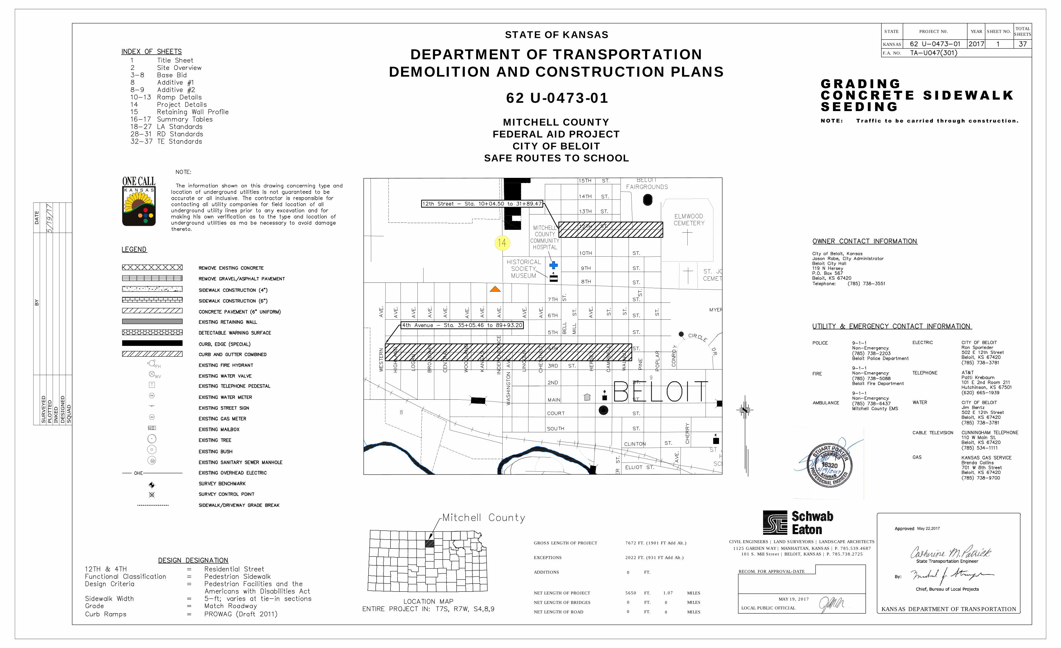
GROSS LENGTH OF PROJECT
NET LENGTH OF ROAD
FT.
NET LENGTH OF BRIDGES
EXCEPTIONS
NET LENGTH OF PROJECT
7672 FT. (1901 FT Add Alt.)
5650
0
0
1.07
0
0
CIVIL ENGINEERS | LAND SURVEYORS | LANDSCAPE ARCHITECTS
1125 GARDEN WAY | MANHATTAN, KANSAS | P. 785.539.4687
101 S. Mill Street | BELOIT, KANSAS | P. 785.738.2725
2022 FT. (931 FT Add Alt.)
0
STATE OF KANSAS
DEPARTMENT OF TRANSPORTATION
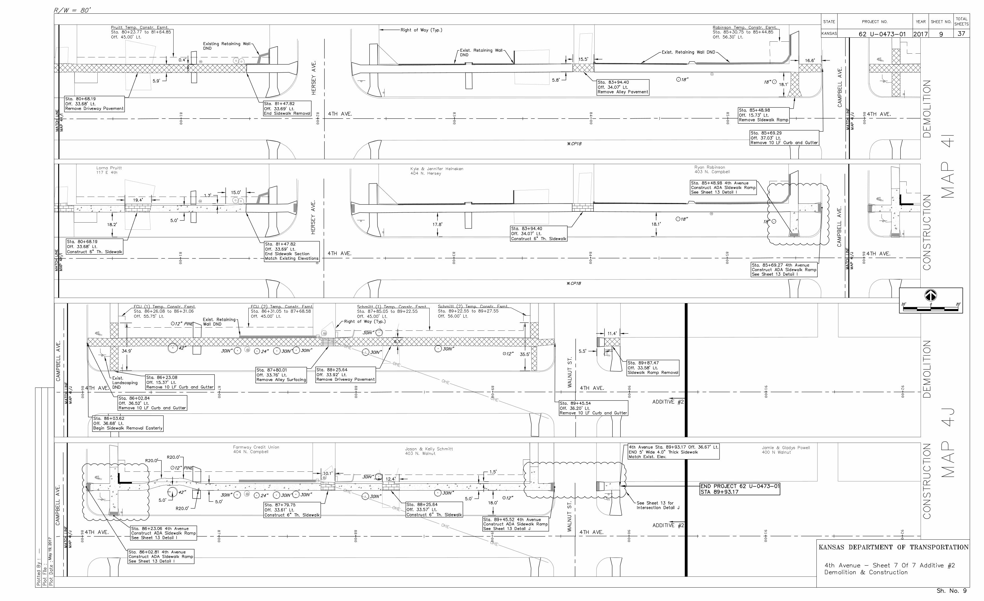
DEMOLITION AND CONSTRUCTION PLANS
62 U-0473-01
MITCHELL COUNTY
FEDERAL AID PROJECT
CITY OF BELOIT
SAFE ROUTES TO SCHOOL
MAY 19, 2017
May 22,2017
----
May
19,
201
7
.
10+
00
11+
00
12+
00
13+
00
14+
00
15+
00
16+
00
16+
00
17+
00
18+
00
19+
00
20+
00
21+
00
22+
00
10+
00
11+
00
12+
00
13+
00
14+
00
15+
00
16+
00
16+
00
17+
00
18+
00
19+
00
20+
00
21+
00
22+
00
----
May
19,
201
7
Y:\P
roje
cts\
13.1
20 S
RTS
Bel
oit\S
afe
Rou
tes
to S
choo
ls\H
aley
\CA
D\S
RTS
Wor
king
File
21+
00
22+
00
23+
00
24+
00
25+
00
26+
00
27+
00
21+
00
22+
00
23+
00
24+
00
25+
00
26+
00
27+
00
28+
00
29+
00
30+
00
31+
00
32+
00
32+
16
28+
00
29+
00
30+
00
31+
00
32+
00
32+
16
----
May
19,
201
7
35+
00
36+
00
37+
00
38+
00
39+
00
40+
00
41+
00
42+
00
43+
00
44+
00
45+
00
46+
00
47+
00
35+
00
36+
00
37+
00
38+
00
39+
00
40+
00
41+
00
42+
00
43+
00
44+
00
45+
00
46+
00
47+
00
----
May
19,
201
7
46+
00
47+
00
48+
00
49+
00
50+
00
51+
00
52+
00
52+
00
53+
00
54+
00
55+
00
56+
00
57+
00
58+
00
46+
00
47+
00
48+
00
49+
00
50+
00
51+
00
52+
00
52+
00
53+
00
54+
00
55+
00
56+
00
57+
00
58+
00
----
May
19,
201
7
58+
00
59+
00
60+
00
61+
00
62+
00
63+
00
64+
00
65+
00
66+
00
67+
00
68+
00
69+
00
70+
00
58+
00
59+
00
60+
00
61+
00
62+
00
63+
00
64+
00
65+
00
66+
00
67+
00
68+
00
69+
00
70+
00
----
May
19,
201
7
75+
00
76+
00
77+
00
78+
00
79+
00
80+
00
70+
00
71+
00
72+
00
73+
00
74+
00
75+
00
70+
00
71+
00
72+
00
73+
00
74+
00
75+
00
75+
00
76+
00
77+
00
78+
00
79+
00
80+
00
----
May
19,
201
7
86+
00
87+
00
88+
00
89+
00
90+
00
91+
00
92+
00
81+
00
82+
00
83+
00
84+
00
85+
00
86+
00
81+
00
82+
00
83+
00
84+
00
85+
00
86+
00
86+
00
87+
00
88+
00
89+
00
90+
00
91+
00
92+
00
----
May
19,
201
7
----
May
19,
201
7
Y:\P
roje
cts\
13.1
20 S
RTS
Bel
oit\S
afe
Rou
tes
to S
choo
ls\H
aley
\CA
D\S
RTS
Wor
king
File
----
May
19,
201
7
Y:\P
roje
cts\
13.1
20 S
RTS
Bel
oit\S
afe
Rou
tes
to S
choo
ls\H
aley
\CA
D\S
RTS
Wor
king
File
----
May
19,
201
7
Y:\P
roje
cts\
13.1
20 S
RTS
Bel
oit\S
afe
Rou
tes
to S
choo
ls\H
aley
\CA
D\S
RTS
Wor
king
File
----
May
19,
201
7
Y:\P
roje
cts\
13.1
20 S
RTS
Bel
oit\S
afe
Rou
tes
to S
choo
ls\H
aley
\CA
D\S
RTS
Wor
king
File
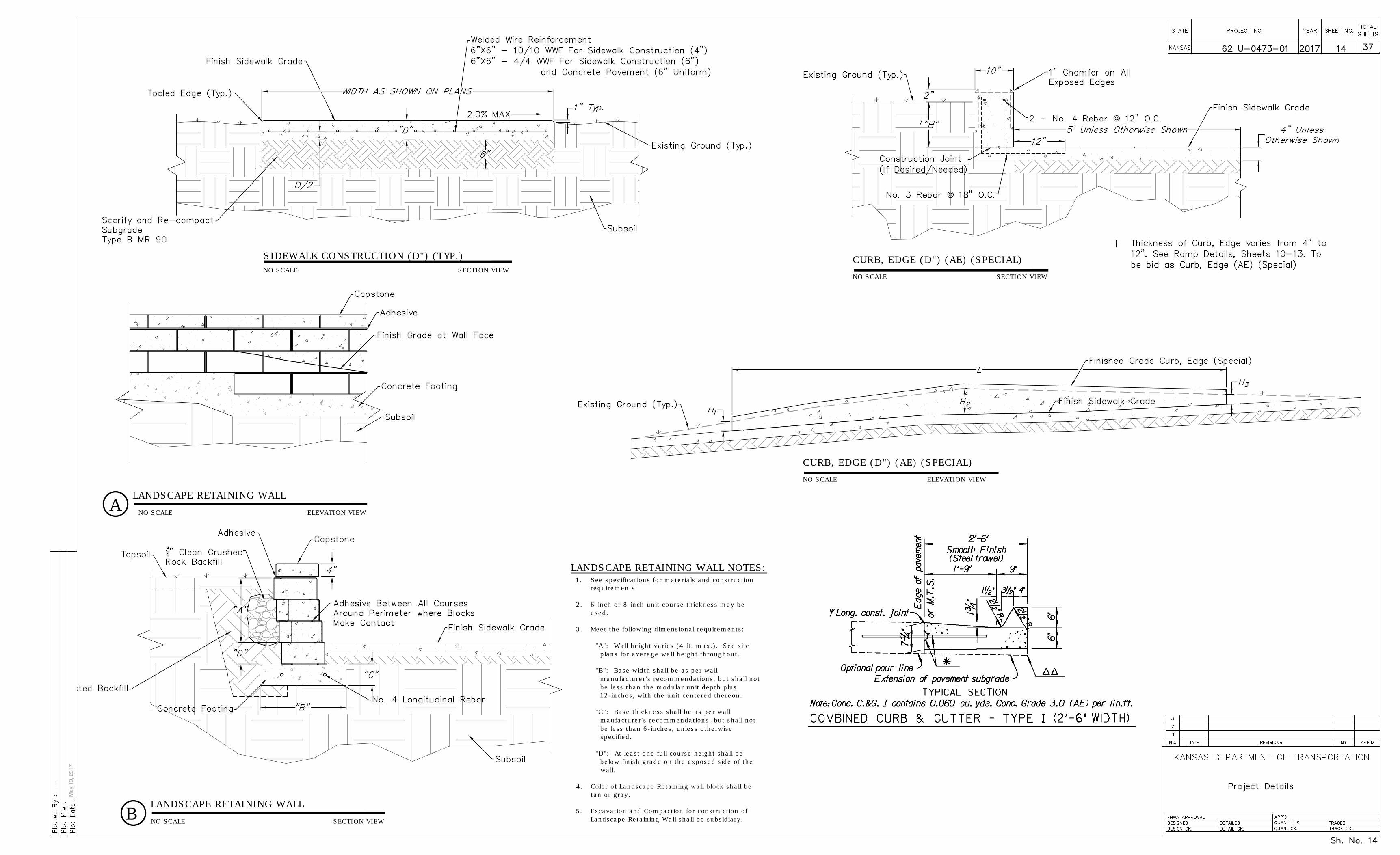
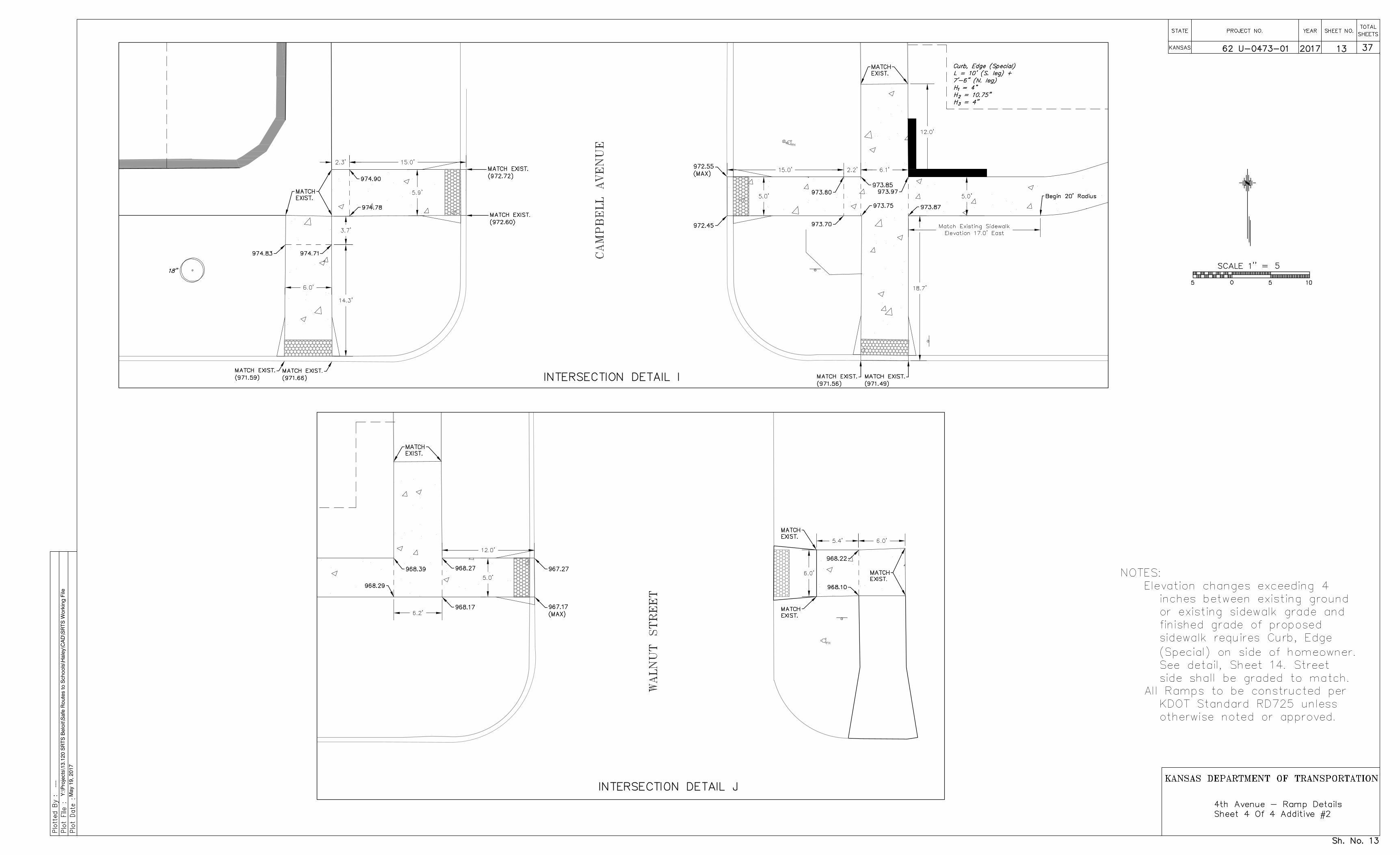
SIDEWALK CONSTRUCTION (D") (TYP.)
B
CURB, EDGE (D") (AE) (SPECIAL)
NO SCALE SECTION VIEW
NO SCALE SECTION VIEW
LANDSCAPE RETAINING WALL
LANDSCAPE RETAINING WALL NOTES:
1. See specifications for materials and construction
requirements.
2. 6-inch or 8-inch unit course thickness may be
used.
3. Meet the following dimensional requirements:
"A": Wall height varies (4 ft. max.). See site
plans for average wall height throughout.
"B": Base width shall be as per wall
manufacturer's recommendations, but shall not
be less than the modular unit depth plus
12-inches, with the unit centered thereon.
"C": Base thickness shall be as per wall
maufacturer's recommendations, but shall not
be less than 6-inches, unless otherwise
specified.
"D": At least one full course height shall be
below finish grade on the exposed side of the
wall.
4. Color of Landscape Retaining wall block shall be
tan or gray.
5. Excavation and Compaction for construction of
Landscape Retaining Wall shall be subsidiary.
A
LANDSCAPE RETAINING WALL
ELEVATION VIEW
SECTION VIEW
NO SCALE
NO SCALE
CURB, EDGE (D") (AE) (SPECIAL)
NO SCALE ELEVATION VIEW
†
----
May
19,
201
7
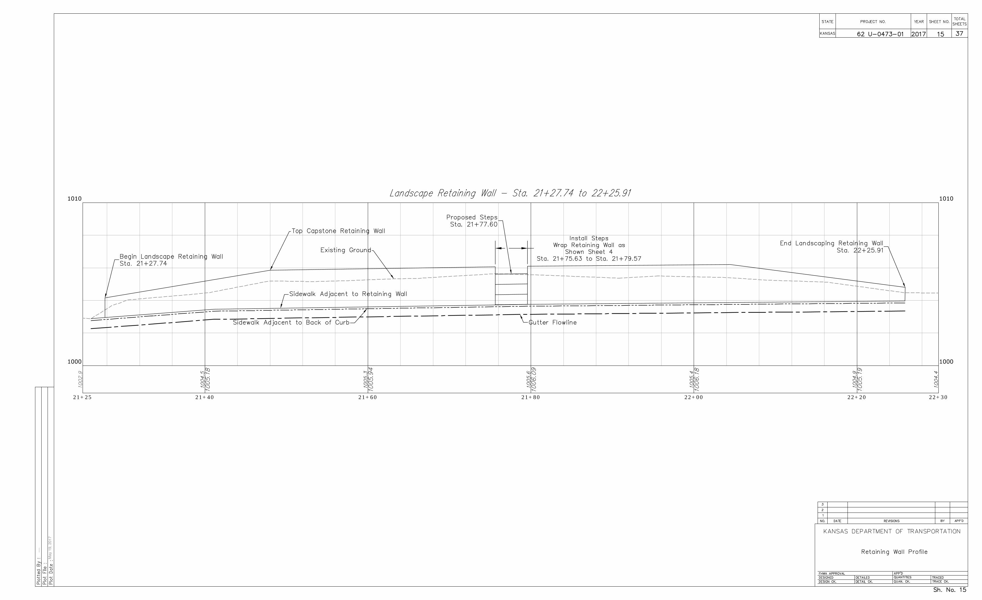
21+25 21+40 21+60 21+80 22+00 22+20 22+30
----
May
19,
201
7
2 1-14-08 S.W.K.Rem. Drainage Structure summary
1 1-9-91 R.J.S J.O.B.Detailed on CADD
J.O.B.
STATE
KANSAS
YEARPROJECT N0.SHEETS
TOTALSHEET NO.
16 rd050
A.d
gn
File :
Dra
wn B
y :
hdougherty
Plotted :19-M
AY-2
017 1
5:3
5
DATE REVISIONS BY APP'DNO.
KANSAS DEPARTMENT OF TRANSPORTATION
FHWA APPROVAL 5-28-08
DESIGNED
DETAILED
DESIGN CK. DETAIL CK. QUAN.CK.
RD050
TRACED B.N.B.
TRACE CK. S.W.K.
QUANTITIES
APP'D. James O. Brewer
2017 16 37
BASE BID
STATION DESCRIPTION
Pampas Grass
10+18.03 Lt.
13+06.00 Lt.
21+35.11 Lt.
21+64.08 Lt.
21+88.71 Lt.
22+08.22 Lt.
22+55.15 Lt.
37+42.50 Lt.
37+60.88 Lt.
44+62.79 Lt.
45+08.65 Lt.
46+78.70 Lt.
46+97.82 Lt.
60+63.77 Lt.
62+43.57 Lt.
24" Tree Stump
30" Siberian Elm
30" Siberian Elm
32" Siberian Elm
18" Hackberry
18" Pine
24" Siberian Elm
18" Tree Stump
Tree Stump
Bush Stump
30" Elm
12" Elm
48" American Elm
30" Peach Tree
STATION DESCRIPTION
ADDITIVE #2
78+73.68 Lt.
79+44.17 Lt.
79+55.96 Lt.
79+71.83 Lt.
18" American Elm
30" Siberian Elm
36" Locust
18" Redbud
BASE BID
STATION DESCRIPTION
13+64.99 Lt.
13+67.71 Lt.
20+71.69 Lt.
22+63.01 Lt.
38+33.13 Lt.
38+87.08 Lt.
39+00.69 Lt.
42+02.99 Lt.
Fire Hydrant
Street Sign
Fire Hydrant
Street Sign
Street Sign
Gas Meter
Water Meter
Mailbox Row
END STA.
11+55.66 Lt.
11+99.69 Lt.
13+27.36 Lt.
14+56.41 Lt.
15+26.73 Lt.
15+59.44 Lt.
16+97.87 Lt.
18+70.46 Lt.
19+08.48 Lt.
19+76.29 Lt.
20+72.88 Lt.
22+26.05 Lt.
25+25.96 Lt.
31+89.47 Lt.
36+01.07 Lt.
36+60.39 Lt.
38+29.04 Lt.
39+36.67 Lt.
39+59.93 Lt.
40+31.71 Lt.
41+97.70 Lt.
43+59.30 Lt.
STATION
72+69.12 Lt.
74+31.40 Lt.
ADDITIVE #1
STATION
79+86.02 Lt.
80+59.18 Lt.
81+47.82 Lt.
87+74.70 Lt.
88+19.42 Lt.
ADDITIVE #2
ADDITIVE #1
16+20.62 Lt.
16+82.10 Lt.
30" Siberian Elm
32" Siberian Elm
62 U-0473-01
22+63.26 Lt.
1402 SF = 155.8 SY
1355 SF = 150.6 SY
1393 SF = 154.8 SY
3734 SF = 414.9 SY
TOTAL BASE BID = 2307.7 SY
854.5 SF = 94.9 SY
TOTAL ADD. #1 = 132.8 SY
TOTAL ADD. #2 = 326.0 SY
36+93.84 Lt.
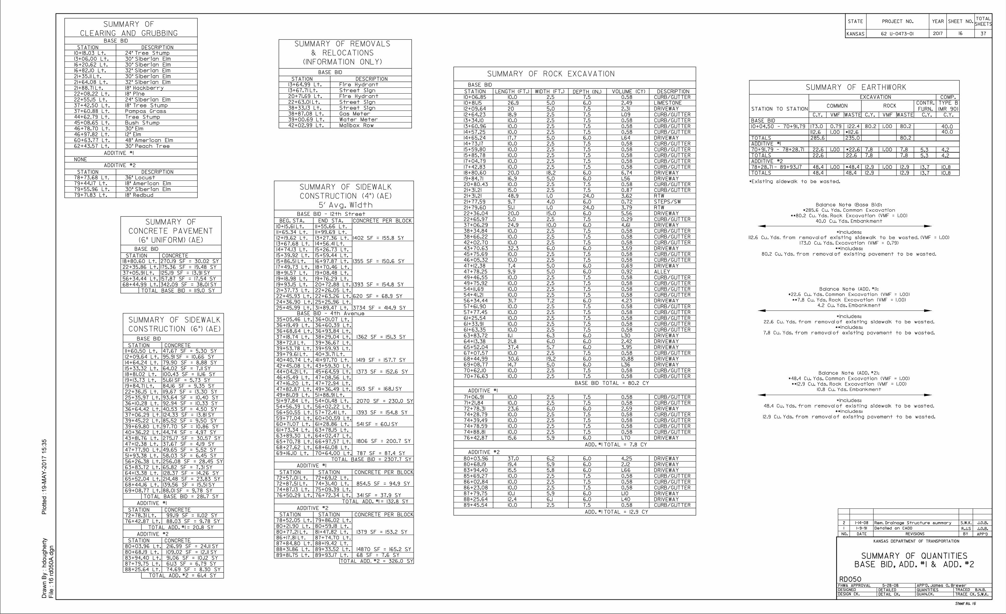
BASE BID, ADD. #1 & ADD. #2
SUMMARY OF QUANTITIES
SUMMARY OF ROCK EXCAVATION
BASE BID
STATION LENGTH (FT.) WIDTH (FT.) DEPTH (IN.) VOLUME (CY)
10+06.85 2.5 7.5
12+09.64
10.0
20
13+34.10
13+60.96
14+65.24
17+04.79
17+42.83
18+80.60
19+84.71
20+80.43
21+31.21
21+79.60
22+36.04
22+65.97
37+06.29
38+34.84
38+66.22
42+02.70
43+70.63
47+12.38
47+78.25
49+46.55
49+75.92
54+11.69
54+41.21
56+34.44
57+61.90
57+77.45
61+25.54
61+33.91
61+63.35
63+83.72
10.8868+44.99
69+08.77
70+62.10
70+76.63
ADDITIVE #1
76+42.87
71+06.91
71+21.84
72+78.31
74+28.79
74+39.49
74+78.59
74+88.81
ADDITIVE #2
80+03.96
80+68.19
83+94.40
85+69.27
86+02.84
86+23.08
87+79.75
88+25.64
89+45.54
10+81.15
14+57.25
14+73.17
15+85.78
15+59.80
45+75.69
46+05.32
0.58
26.9 5.0 6.0 2.49
5.0 7.5
17.7 6.0 1.645.0
18.2 6.020.0
16.9 5.0 6.0
15.0 2.5 7.5
51.1 1.0 24.0
20.0 15.0 6.0
5.0 2.5 7.5
24.9 10.0 6.0
32.3 6.0 6.0
7.4 5.0 6.0
9.9 5.0 6.0
31.7 7.2 6.0
30.6 19.2 6.0
14.7 5.0 6.0
6.0 6.0
15.6 5.9 6.0
37.0
19.4
15.5
6.2
5.9
5.8
6.0
6.0
6.0
10.1
12.4
5.9
6.1
6.0
6.0
2.31
10.0 2.5 7.5 0.58
10.0 2.5 7.5 0.58
10.0 2.5 7.5 0.58
10.0 2.5 7.5 0.58
10.0 2.5 7.5 0.58
10.0 2.5 7.5 0.58
10.0 2.5 7.5 0.58
10.0 2.5 7.5 0.58
10.0 2.5 7.5 0.58
10.0 2.5 7.5 0.58
10.0 2.5 7.5 0.58
10.0 2.5 7.5 0.58
10.0 2.5 7.5 0.58
10.0 2.5 7.5 0.58
10.0 2.5 7.5 0.58
10.0 2.5 7.5 0.58
10.0 2.5 7.5 0.58
10.0 2.5 7.5 0.58
10.0 2.5 7.5 0.58
10.0 2.5 7.5 0.58
10.0 2.5 7.5 0.58
10.0 2.5 7.5 0.58
10.0 2.5 7.5 0.58
10.0 2.5 7.5 0.58
10.0 2.5 7.5 0.58
10.0 2.5 7.5 0.58
10.0 2.5 7.5 0.58
10.0 2.5 7.5 0.58
10.0 2.5 7.5 0.58
10.0 2.5 7.5 0.58
10.0 2.5 7.5 0.58
10.0 2.5 7.5 0.58
10.0 2.5 7.5 0.58
10.0 2.5 7.5 0.58
10.0 2.5 7.5 0.58
6.74
1.56
0.87
3.79
5.56
0.29
4.61
3.59
0.69
0.92
4.23
1.36
2.59
1.70
4.25
2.12
1.66
1.10
1.40
BASE BID TOTAL = 80.2 CY
ADD. #1 TOTAL = 7.8 CY
3.6221+31.21 48.9 1.0
0.7221+77.59 9.7 4.0
24.0
6.0
ADD. #1 TOTAL = 12.9 CY
12+64.23 2.5 7.5 1.0918.9
RTW
RTW
DESCRIPTION
CURB/GUTTER
LIMESTONE
DRIVEWAY
CURB/GUTTER
CURB/GUTTER
CURB/GUTTER
CURB/GUTTER
CURB/GUTTER
CURB/GUTTER
CURB/GUTTER
CURB/GUTTER
CURB/GUTTER
CURB/GUTTER
DRIVEWAY
DRIVEWAY
DRIVEWAY
CURB/GUTTER
DRIVEWAY
CURB/GUTTER
DRIVEWAY
CURB/GUTTER
CURB/GUTTER
CURB/GUTTER
CURB/GUTTER
CURB/GUTTER
CURB/GUTTER
CURB/GUTTER
CURB/GUTTER
CURB/GUTTER
CURB/GUTTER
CURB/GUTTER
CURB/GUTTER
CURB/GUTTER
CURB/GUTTER
CURB/GUTTER
CURB/GUTTER
DRIVEWAY
DRIVEWAY
DRIVEWAY
DRIVEWAY
DRIVEWAY
CURB/GUTTER
CURB/GUTTER
CURB/GUTTER
CURB/GUTTER
CURB/GUTTER
CURB/GUTTER
CURB/GUTTER
CURB/GUTTER
CURB/GUTTER
DRIVEWAY
DRIVEWAY
DRIVEWAY
DRIVEWAY
CURB/GUTTER
DRIVEWAY
DRIVEWAY
23.6 DRIVEWAY
(INFORMATION ONLY)
& RELOCATIONS
SUMMARY OF REMOVALS
Sheet No. 16
CLEARING AND GRUBBING
SUMMARY OF
BASE BID
STATION
11+60.50 Lt.
12+09.64 Lt.
14+64.24 Lt.
15+33.32 Lt.
18+81.02 Lt.
19+13.73 Lt.
19+84.71 Lt.
22+36.15 Lt.
25+35.97 Lt.
36+10.28 Lt.
36+64.42 Lt.
37+06.29 Lt.
39+69.80 Lt.
40+36.22 Lt.
43+81.76 Lt.
47+12.38 Lt.
47+77.90 Lt.
56+26.38 Lt.
63+83.72 Lt.
64+13.38 Lt.
65+52.04 Lt.
68+44.16 Lt.
69+08.77 Lt.
CONSTRUCTION (6") (AE)
SUMMARY OF SIDEWALK
STATION
72+78.31 Lt.
76+42.87 Lt.
ADDITIVE #1
STATION
80+03.96 Lt.
80+68.19 Lt.
83+94.40 Lt.
87+79.75 Lt.
88+25.64 Lt.
ADDITIVE #2
39+45.22 Lt.
47.67 SF = 5.30 SY
95.91 SF = 10.66 SY
79.90 SF = 8.88 SY
64.02 SF = 7.11 SY
100.43 SF = 11.16 SY
51.61 SF = 5.73 SY
84.16 SF = 9.35 SY
119.67 SF = 13.30 SY
93.64 SF = 10.40 SY
92.94 SF = 10.33 SY
40.53 SF = 4.50 SY
124.33 SF = 13.81 SY
85.52 SF = 9.50 SY
97.70 SF = 10.86 SY
44.74 SF = 4.97 SY
275.17 SF = 30.57 SY
37.67 SF = 4.19 SY
49.65 SF = 5.52 SY
256.08 SF = 28.45 SY
65.82 SF = 7.31 SY
128.37 SF = 14.26 SY
214.48 SF = 23.83 SY
139.56 SF = 15.51 SY
88.01 SF = 9.78 SY
TOTAL BASE BID = 281.7 SY
99.19 SF = 11.02 SY
88.03 SF = 9.78 SY
216.99 SF = 24.11 SY
109.02 SF = 12.11 SY
91.06 SF = 10.12 SY
61.13 SF = 6.79 SY
74.69 SF = 8.30 SY
TOTAL ADD. #1 = 20.8 SY
TOTAL ADD. #2 = 61.4 SY
58.03 SF = 6.45 SY51+93.38 Lt.
CONCRETE
CONCRETE
CONCRETE
10+15.61 Lt.
11+65.34 Lt.
12+19.62 Lt.
13+67.68 Lt.
14+74.13 Lt.
15+39.92 Lt.
15+86.51 Lt.
17+49.73 Lt.
18+91.57 Lt.
19+18.98 Lt.
19+93.15 Lt.
21+37.73 Lt.
24+36.90 Lt.
25+45.99 Lt.
35+05.46 Lt.
36+19.49 Lt.
37+18.74 Lt.
38+72.11 Lt.
39+53.78 Lt.
39+79.61 Lt.
40+40.74 Lt.
42+45.08 Lt.
STATION
72+57.01 Lt.
72+87.51 Lt.
STATION
78+52.05 Lt.
80+21.90 Lt.
80+77.21 Lt.
86+17.81 Lt.
87+84.80 Lt.
22+45.93 Lt.
36+68.64 Lt.
BEG. STA.
47+08.56 Lt.
47+72.94 Lt.
49+36.49 Lt.
51+88.91 Lt.
54+01.48 Lt.
1419 SF = 157.7 SY
45+64.59 Lt.
46+15.49 Lt.
47+16.20 Lt.
47+82.87 Lt.
49+81.09 Lt.
51+97.84 Lt.
44+04.21 Lt.
57+72.41 Lt.
60+00.59 Lt.
61+28.86 Lt.
63+78.15 Lt.
64+02.47 Lt.
56+02.22 Lt.
56+50.55 Lt.
59+77.04 Lt.
60+71.07 Lt.
61+73.34 Lt.
63+89.30 Lt.
54+56.39 Lt.
68+61.08 Lt.
70+64.00 Lt.
66+97.57 Lt.
68+27.62 Lt.
69+16.10 Lt.
65+70.78 Lt.
75+09.39 Lt.
76+72.34 Lt.
74+87.13 Lt.
76+50.29 Lt.
89+33.52 Lt.
89+93.17 Lt.
88+31.86 Lt.
89+81.75 Lt.
CONCRETE PER BLOCK
620 SF = 68.9 SY
1362 SF = 151.3 SY
1373 SF = 152.6 SY
1513 SF = 168.1 SY
2070 SF = 230.0 SY
1393 SF = 154.8 SY
541 SF = 60.1 SY
1806 SF = 200.7 SY
787 SF = 87.4 SY
CONCRETE PER BLOCK
CONCRETE PER BLOCK
341 SF = 37.9 SY
1379 SF = 153.2 SY
14870 SF = 165.2 SY
68 SF = 7.6 SY
BASE BID - 12th Street
BASE BID - 4th Avenue
5' Avg. Width
CONSTRUCTION (4") (AE)
SUMMARY OF SIDEWALK
NONE
STEPS/SW
ALLEY
64+13.38
65+52.04
CURB/GUTTER0.587.52.510.067+07.57
DRIVEWAY
DRIVEWAY
6.0
6.0
6.0
DRIVEWAY
11.1 6.3
21.8 6.0
37.4 5.7
1.30
2.42
3.95
SUMMARY OF EARTHWORK
EXCAVATION
COMMON
C.Y. VMF C.Y. VMF
10+04.50 - 70+91.79
70+91.79 - 78+28.71
78+28.71 - 89+93.17
BASE BID
ADDITIVE #1
ADDITIVE #2
0.79 80.2 1.00
22.6 1.00 7.8 1.00
48.4 1.00 12.9 1.00
173.0
TOTALS
STATION TO STATION
WASTE C.Y.
5.3
13.712.9
80.2
7.8
WASTE
112.6 1.00 *112.6
122.4
†ROCK
*22.6
*48.4
*Existing sidewalk to be wasted.
Existing pavement, landscaping, and curb and gutter to be wasted.†
TOTALS
TOTALS
(MR 90)
TYPE B
FURN.
CONTR.
C.Y.
40.0
4.2
10.8
285.6 235.0
22.6 7.8 7.8 5.3 4.2
10.813.748.4 12.9 12.9
40.0
48.4
22.6
80.2
80.2 Cu. Yds. from removal of existing pavement to be wasted.
**Includes:
173.0 Cu. Yds. Excavation (VMF = 0.79)
112.6 Cu. Yds. from removal of existing sidewalk to be wasted. (VMF = 1.00)
*Includes:
40.0 Cu. Yds. Embankment
**80.2 Cu. Yds. Rock Excavation (VMF = 1.00)
*285.6 Cu. Yds. Common Excavation
Balance Note (Base Bid):
7.8 Cu. Yds. from removal of existing pavement to be wasted.
**Includes:
22.6 Cu. Yds. from removal of existing sidewalk to be wasted.
*Includes:
4.2 Cu. Yds. Embankment
**7.8 Cu. Yds. Rock Excavation (VMF = 1.00)
*22.6 Cu. Yds. Common Excavation (VMF = 1.00)
Balance Note (ADD. #1):
12.9 Cu. Yds. from removal of existing pavement to be wasted.
**Includes:
48.4 Cu. Yds. from removal of existing sidewalk to be wasted.
*Includes:
10.8 Cu. Yds. Embankment
**12.9 Cu. Yds. Rock Excavation (VMF = 1.00)
*48.4 Cu. Yds. Common Excavation (VMF = 1.00)
Balance Note (ADD. #2):
COMP.
BASE BID
STATION
18+80.60 Lt.
22+35.86 Lt.
37+05.91 Lt.
56+34.44 Lt.
68+44.99 Lt.
270.19 SF = 30.02 SY
175.36 SF = 19.48 SY
125.19 SF = 13.91 SY
157.87 SF = 17.54 SY
342.09 SF = 38.01 SY
TOTAL BASE BID = 119.0 SY
CONCRETE
(6" UNIFORM) (AE)
CONCRETE PAVEMENT
SUMMARY OF
2 1-14-08 S.W.K.Rem. Drainage Structure summary
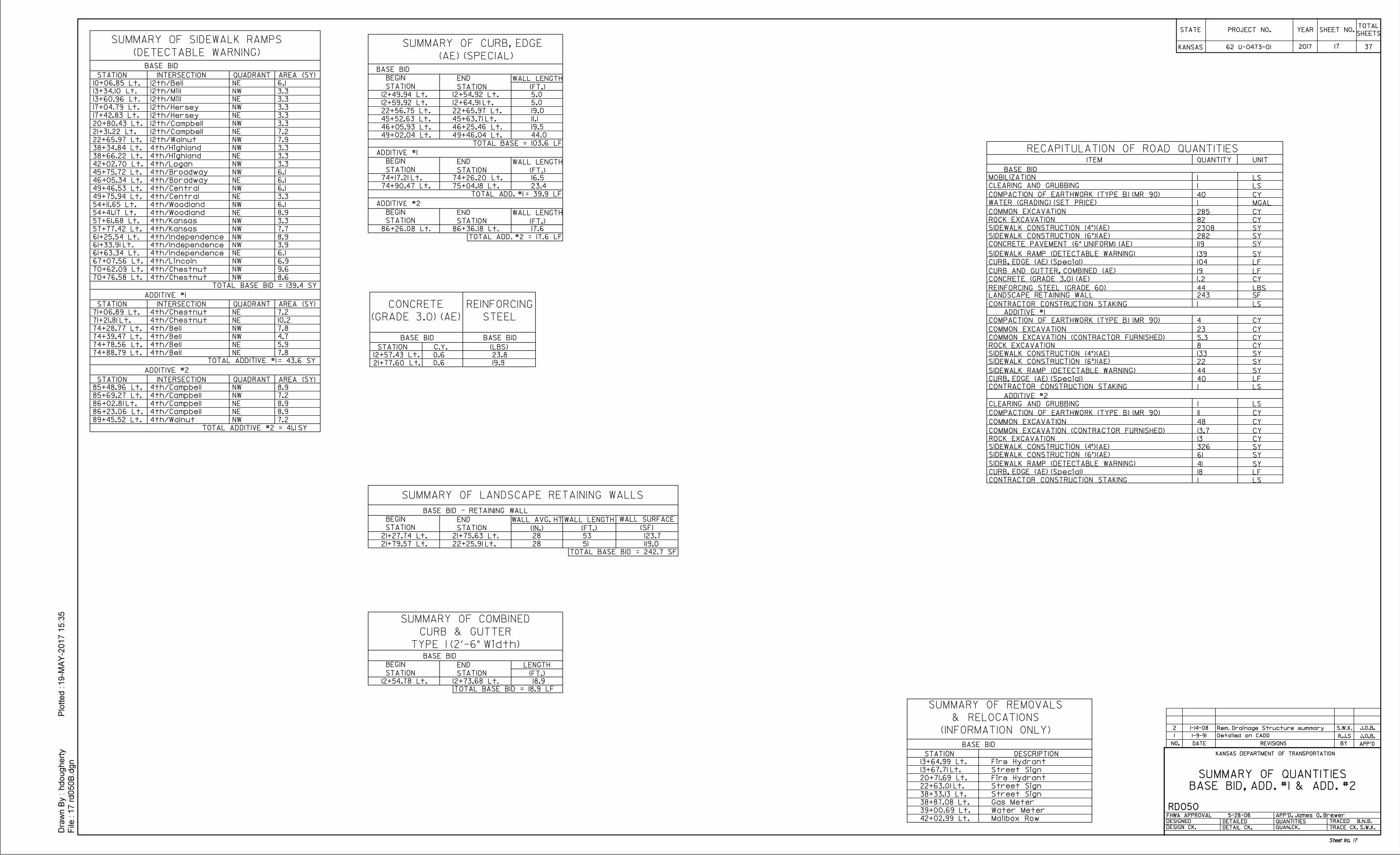
RECAPITULATION OF ROAD QUANTITIESITEM QUANTITY UNIT
1 1-9-91 R.J.S J.O.B.Detailed on CADD
J.O.B.
STATE
KANSAS
YEARPROJECT N0.SHEETS
TOTALSHEET NO.
17 rd050
B.d
gn
File :
Dra
wn B
y :
hdougherty
Plotted :19-M
AY-2
017 1
5:3
5
DATE REVISIONS BY APP'DNO.
KANSAS DEPARTMENT OF TRANSPORTATION
FHWA APPROVAL 5-28-08
DESIGNED
DETAILED
DESIGN CK. DETAIL CK. QUAN.CK.
RD050
TRACED B.N.B.
TRACE CK. S.W.K.
QUANTITIES
APP'D. James O. Brewer
2017 17 37
BASE BID
STATION DESCRIPTION
13+64.99 Lt.
13+67.71 Lt.
20+71.69 Lt.
22+63.01 Lt.
38+33.13 Lt.
38+87.08 Lt.
39+00.69 Lt.
42+02.99 Lt.
Fire Hydrant
Street Sign
Fire Hydrant
Street Sign
Street Sign
Gas Meter
Water Meter
Mailbox Row
BASE BID
STATION INTERSECTION
10+06.85 Lt.
13+34.10 Lt.
13+60.96 Lt.
17+04.79 Lt.
17+42.83 Lt.
20+80.43 Lt.
21+31.22 Lt.
22+65.97 Lt.
38+34.84 Lt.
38+66.22 Lt.
42+02.70 Lt.
45+75.72 Lt.
46+05.34 Lt.
49+46.53 Lt.
49+75.94 Lt.
4th/Logan
QUADRANT
4th/Chestnut
54+11.65 Lt.
54+41.17 Lt.
57+61.68 Lt.
57+77.42 Lt.
61+25.54 Lt.
61+33.91 Lt.
61+63.34 Lt.
67+07.56 Lt.
70+62.09 Lt.
70+76.58 Lt.
4th/Independence
STATION INTERSECTION
71+06.89 Lt.
71+21.81 Lt.
74+28.77 Lt.
74+39.47 Lt.
74+78.56 Lt.
74+88.79 Lt. 4th/Bell
QUADRANT
ADDITIVE #1
STATION INTERSECTION
85+69.27 Lt.
86+02.81 Lt.
86+23.06 Lt.
89+45.52 Lt.
QUADRANT
ADDITIVE #2
12th/Bell
12th/Mill
12th/Mill
12th/Hersey
12th/Hersey
12th/Campbell
12th/Campbell
12th/Walnut
4th/Highland
4th/Highland
4th/Broadway
4th/Boradway
4th/Central
4th/Central
4th/Woodland
4th/Woodland
4th/Kansas
4th/Kansas
4th/Independence
4th/Independence
4th/Lincoln
4th/Chestnut
NE
NW
NE
NW
NE
NW
NE
NW
NW
NE
NW
NW
NE
NW
NE
NW
NE
NW
NW
NW
NW
NE
NW
NW
NW
4th/Chestnut
4th/Chestnut
4th/Bell
4th/Bell
4th/Bell
4th/Campbell
4th/Campbell
4th/Campbell
4th/Walnut
NE
NE
NW
NW
NE
NE
NW
NE
NE
NW
21+27.74 Lt.
21+79.57 Lt.
45+52.63 Lt.
46+05.93 Lt.
49+02.04 Lt.
74+17.21 Lt.
74+90.47 Lt.
86+26.08 Lt.
21+75.63 Lt.
22+25.91 Lt.
45+63.71 Lt.
46+25.46 Lt.
49+46.04 Lt.
74+26.20 Lt.
75+04.18 Lt.
86+36.18 Lt.
STATION
BEGIN
STATION
END
(IN.)
WALL AVG. HT
(FT.)
WALL LENGTH
STATION
BEGIN
STATION
END
(FT.)
WALL LENGTH
STATION
BEGIN
STATION
END
(FT.)
WALL LENGTH
STATION
BEGIN
STATION
END
(FT.)
WALL LENGTH
28 53
5128
BASE BID
MOBILIZATION
ADDITIVE #1
SUMMARY OF LANDSCAPE RETAINING WALLS
(SF)
WALL SURFACE
123.7
119.0
CLEARING AND GRUBBING
COMPACTION OF EARTHWORK (TYPE B) (MR 90)
ROCK EXCAVATION
1 LS
1 LS
CY
CY
CY
SY
SY
SY
LF
SF
285
282
139
243
1
22+56.75 Lt. 22+65.97 Lt.
BASE BID
ADDITIVE #1
ADDITIVE #2
COMMON EXCAVATION
82
SIDEWALK CONSTRUCTION (4")(AE) 2308
SIDEWALK CONSTRUCTION (6")(AE)
LANDSCAPE RETAINING WALL
CONTRACTOR CONSTRUCTION STAKING LS
COMPACTION OF EARTHWORK (TYPE B) (MR 90)
ROCK EXCAVATION
CY
CY
CY
SY
SY
SY
LF
COMMON EXCAVATION
8
SIDEWALK CONSTRUCTION (4")(AE) 133
SIDEWALK CONSTRUCTION (6")(AE)
40
ADDITIVE #2
CY
CY
CY
SY
SY
SY
13
326
CLEARING AND GRUBBING
COMPACTION OF EARTHWORK (TYPE B) (MR 90)
ROCK EXCAVATION
1 LS
LF
COMMON EXCAVATION
SIDEWALK CONSTRUCTION (4")(AE)
SIDEWALK CONSTRUCTION (6")(AE)
18
4
23
22
44
11
48
61
41
62 U-0473-01
BASE BID - RETAINING WALL
BASE BID, ADD. #1 & ADD. #2
SUMMARY OF QUANTITIES
19.5
19.0
11.1
44.0
16.5
23.4
17.6
TOTAL BASE BID = 242.7 SF
AREA (SY)
3.3
3.3
6.1
3.3
3.3
3.3
7.2
7.9
3.3
3.3
3.3
6.1
6.1
6.1
3.3
6.1
8.9
3.3
7.7
8.9
3.9
6.1
6.9
9.6
8.6
AREA (SY)
AREA (SY)
7.2
10.2
7.8
4.7
5.9
7.8
7.2
8.9
8.9
7.2
TOTAL BASE BID = 139.4 SY
TOTAL ADDITIVE #1 = 43.6 SY
TOTAL ADDITIVE #2 = 41.1 SY
12+59.92 Lt. 12+64.91 Lt.
12+54.92 Lt. 5.0
5.0
12+49.94 Lt.
8.985+48.96 Lt. 4th/Campbell NW
LF
CY
CURB AND GUTTER, COMBINED (AE)
CONCRETE (GRADE 3.0) (AE) 1.2
BASE BID
STATION
12+57.43 Lt.
21+77.60 Lt.
0.6
0.6
(GRADE 3.0) (AE)
CONCRETE
(LBS)
23.8
19.9
(INFORMATION ONLY)
& RELOCATIONS
SUMMARY OF REMOVALS
TOTAL BASE = 103.6 LF
TOTAL ADD. #1 = 39.9 LF
TOTAL ADD. #2 = 17.6 LF
REINFORCING STEEL (GRADE 60) LBS
Sheet No. 17
(DETECTABLE WARNING)
SUMMARY OF SIDEWALK RAMPS
12+54.78 Lt. 12+73.68 Lt.
BASE BID
(FT.)
LENGTH
STATION
BEGIN
STATION
END
TYPE I (2'-6" Width)
CURB & GUTTER
SUMMARY OF COMBINED
18.9
TOTAL BASE BID = 18.9 LF
STEEL
REINFORCING
BASE BID
SIDEWALK RAMP (DETECTABLE WARNING)
SIDEWALK RAMP (DETECTABLE WARNING)
SIDEWALK RAMP (DETECTABLE WARNING)
104
19
C.Y.
44
40
CYCOMMON EXCAVATION (CONTRACTOR FURNISHED) 5.3
CYCOMMON EXCAVATION (CONTRACTOR FURNISHED) 13.7
LS1CONTRACTOR CONSTRUCTION STAKING
LS1CONTRACTOR CONSTRUCTION STAKING
CURB, EDGE (AE) (Special)
CURB, EDGE (AE) (Special)
CURB, EDGE (AE) (Special)
(AE) (SPECIAL)
SUMMARY OF CURB, EDGE
1WATER (GRADING) (SET PRICE) MGAL
SY119CONCRETE PAVEMENT (6" UNIFORM) (AE)
1
COOL SEASON
February 15 to April 20
and
August 15 to Sept. 30
WARM SEASON
SPECIES SPECIES
Bluegrasses
Bromegrasses
Fescues
Indiangrass
November 15 to June 1
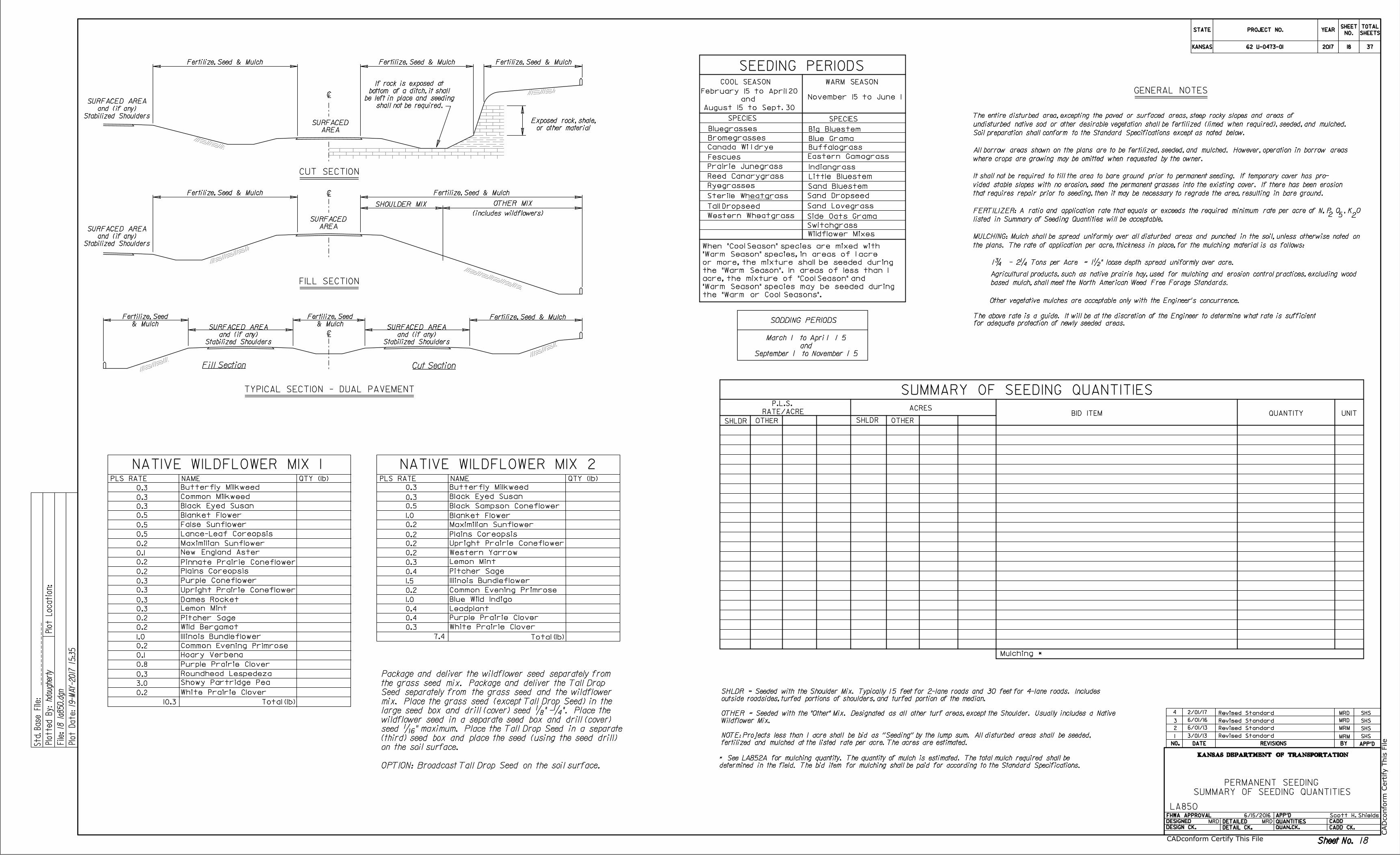
undisturbed native sod or other desirable vegetation shall be fertilized (limed when required), seeded, and mulched.
All borrow areas shown on the plans are to be fertilized, seeded, and mulched. However, operation in borrow areas
where crops are growing may be omitted when requested by the owner.
MULCHING: Mulch shall be spread uniformly over all disturbed areas and punched in the soil, unless otherwise noted on
1ƒ - 2‚ Tons per Acre = 1•"loose depth spread uniformly over acre.
for adequate protection of newly seeded areas.
FERTILIZER: A ratio and application rate that equals or exceeds the required minimum rate per acre of N, P O , K O2 25
It shall not be required to till the area to bare ground prior to permanent seeding. If temporary cover has pro-
Soil preparation shall conform to the Standard Specifications except as noted below.
vided stable slopes with no erosion, seed the permanent grasses into the existing cover. If there has been erosion
that requires repair prior to seeding, then it may be necessary to regrade the area, resulting in bare ground.
listed in Summary of Seeding Quantities will be acceptable.
the plans. The rate of application per acre, thickness in place, for the mulching material is as follows:
The above rate is a guide. It will be at the discretion of the Engineer to determine what rate is sufficient
Agricultural products, such as native prairie hay, used for mulching and erosion control practices, excluding wood
SEEDING PERIODS
SUMMARY OF SEEDING QUANTITIESTYPICAL SECTION - DUAL PAVEMENT
Fill Section Cut Section
CUT SECTION
FILL SECTION
Fertilize, Seed & Mulch Fertilize, Seed & MulchFertilize, Seed & Mulch
Fertilize, Seed & MulchFertilize, Seed & Mulch
UNIT
SHLDR SHLDROTHER OTHER
Canada Wi l drye
BID ITEM QUANTITY
SODDING PERIODS
ACRES
SHOULDER MIX
PERMANENT SEEDING
SUMMARY OF SEEDING QUANTITIES
LA850
based mulch, shall meet the North American Weed Free Forage Standards.
PLS RATE NAME QTY (lb)
Total (lb)
MRM
NATIVE WILDFLOWER MIX 1PLS RATE NAME QTY (lb)
Total (lb)
NATIVE WILDFLOWER MIX 2
MRD
6/01/13
MRD
6/15/2016
MRM
Stabilized Shoulders
and (if any)
SURFACED AREA
Stabilized Shoulders
and (if any)
SURFACED AREA& Mulch
Fertilize, Seed
& Mulch
Fertilize, Seed
Stabilized Shoulders
and (if any)
SURFACED AREA
Stabilized Shoulders
and (if any)
SURFACED AREA
AREA
SURFACED
AREA
SURFACED
September 1 to November 1 5
and
March 1 to Apri l 1 5
GENERAL NOTES
The entire disturbed area, excepting the paved or surfaced areas, steep rocky slopes and areas of
2
3
shall not be required.
be left in place and seeding
bottom of a ditch, it shall
If rock is exposed at
or other material
Exposed rock, shale,
4
Revised Standard SHS
Scott H. Shields
Revised Standard SHS
Revised Standard SHS
Revised Standard SHS
the "Warm or Cool Seasons".
"Warm Season" species may be seeded during
acre, the mixture of "Cool Season" and
the "Warm Season". In areas of less than 1
or more, the mixture shall be seeded during
"Warm Season" species, in areas of 1 acre
When "Cool Season" species are mixed with
RATE/ACRE
P.L.S.
STATE
KANSAS
PROJECT NO. YEARSHEET
NO.
TOTAL
SHEETS
KANSAS DEPARTMENT OF TRANSPORTATION
DATE REVISIONS BY APP'DNO.
DESIGNED
DESIGN CK.
DETAILED
DETAIL CK.
QUANTITIES
QUAN.CK.
APP'DFHWA APPROVAL
CADD
CADD CK.
Std.
Base
File:
18 la
850.d
gn
19-
MA
Y-2017 15:3
5
hdougherty
Plotte
d
By:
File:
Plot
Locatio
n:
Plot
Date:
ì
ì
ì
Big Bluestem
Blue Grama
Buffalograss
Eastern Gamagrass
Little Bluestem
Sand Bluestem
Sand Dropseed
Sand Lovegrass
Side Oats Grama
Switchgrass
Wildflower Mixes
Prairie Junegrass
Reed Canarygrass
Ryegrasses
Sterile Wheatgrass
Tall Dropseed
Western Wheatgrass
Other vegetative mulches are acceptable only with the Engineer's concurrence.
3/01/13
Sheet No.
MRD MRD
Sheet No.Sheet No.
2017
OPTION: Broadcast Tall Drop Seed on the soil surface.
on the soil surface.
(third) seed box and place the seed (using the seed drill)
seed ˆ" maximum. Place the Tall Drop Seed in a separate
wildflower seed in a separate seed box and drill (cover)
large seed box and drill (cover) seed „" -‚". Place the
mix. Place the grass seed (except Tall Drop Seed) in the
Seed separately from the grass seed and the wildflower
the grass seed mix. Package and deliver the Tall Drop
Package and deliver the wildflower seed separately from
2/01/17
Mulching *
determined in the field. The bid item for mulching shall be paid for according to the Standard Specifications.
* See LA852A for mulching quantity. The quantity of mulch is estimated. The total mulch required shall be
fertilized and mulched at the listed rate per acre. The acres are estimated.
NOTE: Projects less than 1 acre shall be bid as ''Seeding'' by the lump sum. All disturbed areas shall be seeded,
Wildflower Mix.
OTHER = Seeded with the "Other" Mix. Designated as all other turf areas, except the Shoulder. Usually includes a Native
outside roadsides, turfed portions of shoulders, and turfed portion of the median.
SHLDR = Seeded with the Shoulder Mix. Typically 15 feet for 2-lane roads and 30 feet for 4-lane roads. Includes
OTHER MIX
(includes wildflowers)
Fertilize, Seed & Mulch
CA
Dconform C
ertify T
his File
CADconform Certify This File
0.3
0.3
0.3
0.5
0.5
0.5
0.2
0.1
0.2
0.2
0.3
0.3
0.3
0.3
0.2
0.2
1.0
0.2
0.1
0.8
0.3
3.0
0.2
10.3
Butterfly Milkweed
Common Milkweed
Black Eyed Susan
Blanket Flower
False Sunflower
Lance-Leaf Coreopsis
Maximilian Sunflower
New England Aster
Pinnate Prairie Coneflower
Plains Coreopsis
Purple Coneflower
Upright Prairie Coneflower
Dames Rocket
Lemon Mint
Pitcher Sage
Wild Bergamot
Illinois Bundleflower
Common Evening Primrose
Hoary Verbena
Purple Prairie Clover
Roundhead Lespedeza
Showy Partridge Pea
White Prairie Clover
0.3
0.3
0.5
1.0
0.2
0.2
0.2
0.2
0.3
0.4
1.5
0.2
1.0
0.4
0.4
0.3
7.4
Butterfly Milkweed
Black Eyed Susan
Black Sampson Coneflower
Blanket Flower
Maximilian Sunflower
Plains Coreopsis
Upright Prairie Coneflower
Western Yarrow
Lemon Mint
Pitcher Sage
Illinois Bundleflower
Common Evening Primrose
Blue Wild Indigo
Leadplant
Purple Prairie Clover
White Prairie Clover
6/01/16
18 37
18
62 U-0473-01

111 111 111
111 111111
111 111 111
111111
111
111111
111
6/15/2016
SOIL EROSION MIX
Erosion Control (Class 1, Type Y)
CU YD
CU YD
LF
LF
CU YD
P.L.S. RATE/ ACRE
CLT CLTSL/CH SL/CH
Soil Erosion Mix
undisturbed native sod or other desirable vegetation shall be fertilized (limed when required), seeded, and mulched.
Soil preparation shall conform to the Standard Specifications.
2 25
Temporary Sediment Basin
Temporary Slope Drain
Temporary Stream Crossing
Temporary Inlet Sediment Barrier
1ƒ - 2‚ Tons per Acre = 1•"loose depth spread uniformly over acre.
TYPICAL SECTION - DUAL PAVEMENT
FILL SECTION CUT SECTION
RAMP FILL SECTION
RAMP CUT SECTION
Fertilize, Seed & Mulch
ACRESBID ITEM QUANTITY UNIT
* - N = Nitrogen Rate of Application
** - P O = Phosphorous Rate of Application
*** - K O = Potassium Rate of Application
Mulch Tacking Slurry
PLS RATE NAME QTY (lb)
Total (lb)
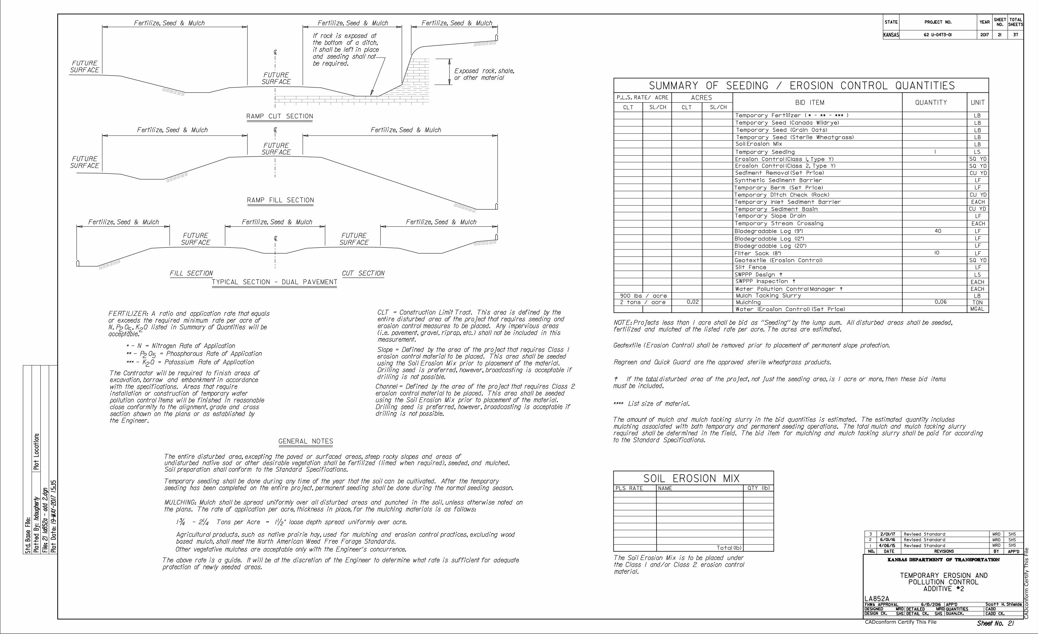
TEMPORARY EROSION AND
LA852A
MRD
MRD
Sediment Removal (Set Price)
MRD
LF
4/06/15
ì
ì
ì
SURFACE
FUTURE
be required.
and seeding shall not
it shall be left in place
the bottom of a ditch,
If rock is exposed at
SURFACE
FUTURE
Fertilize, Seed & MulchFertilize, Seed & Mulch
SURFACE
FUTURE
SURFACE
FUTURE
Fertilize, Seed & Mulch Fertilize, Seed & Mulch
SURFACE
FUTURE
SURFACE
FUTURE
Fertilize, Seed & Mulch Fertilize, Seed & Mulch Fertilize, Seed & Mulch
the plans. The rate of application per acre, thickness in place, for the mulching materials is as follows:
MULCHING: Mulch shall be spread uniformly over all disturbed areas and punched in the soil, unless otherwise noted on
The entire disturbed area, excepting the paved or surfaced areas, steep rocky slopes and areas of
GENERAL NOTES
based mulch, shall meet the North American Weed Free Forage Standards.
Agricultural products, such as native prairie hay, used for mulching and erosion control practices, excluding wood
acceptable.
N, P O , K O listed in Summary of Quantities will be
or exceeds the required minimum rate per acre of
FERTILIZER: A ratio and application rate that equals
the Engineer.
section shown on the plans or as established by
close conformity to the alignment, grade and cross
pollution control items will be finished in reasonable
installation or construction of temporary water
with the specifications. Areas that require
excavation, borrow and embankment in accordance
The Contractor will be required to finish areas of
52
2
STATE
KANSAS
PROJECT NO. YEARSHEET
NO.
TOTAL
SHEETS
KANSAS DEPARTMENT OF TRANSPORTATION
DATE REVISIONS BY APP'DNO.
DESIGNED
DESIGN CK.
DETAILED
DETAIL CK.
QUANTITIES
QUAN.CK.
APP'DFHWA APPROVAL
CADD
CADD CK.
Std.
Base
File:
19 la
852a - B
AS
EBID.d
gn
19-
MA
Y-2017 15:3
5
hdougherty
Plotte
d
By:
File:
Plot
Locatio
n:
Plot
Date:
NO.
1
2
3
SHS SHS
Revised Standard SHS
Revised Standard SHS
Revised Standard SHS
or other material
Exposed rock, shale,
measurement.
(i.e. pavement, gravel, riprap, etc.) shall not be included in this
erosion control measures to be placed. Any impervious areas
entire disturbed area of the project that requires seeding and
CLT = Construction Limit Tract. This area is defined by the
LF
LF
Regreen and Quick Guard are the approved sterile wheatgrass products.
MRD MRD
Temporary Berm (Set Price)
Temporary Ditch Check (Rock)
TON
Silt Fence
LB
LB
LB
LB
EACH
EACH
LB
Temporary Fertilizer ( * - ** - *** )
Erosion Control (Class 2, Type Y) SQ YD
drilling is not possible.
Drilling seed is preferred, however, broadcasting is acceptable if
using the Soil Erosion Mix prior to placement of the material.
erosion control material to be placed. This area shall be seeded
Slope = Defined by the area of the project that requires Class 1
drilling is not possible.
Drilling seed is preferred, however, broadcasting is acceptable if
using the Soil Erosion Mix prior to placement of the material.
erosion control material to be placed. This area shall be seeded
Channel = Defined by the area of the project that requires Class 2
LSSWPPP Design à
SWPPP Inspection à
fertilized and mulched at the listed rate per acre. The acres are estimated.
NOTE: Projects less than 1 acre shall be bid as ''Seeding'' by the lump sum. All disturbed areas shall be seeded,
Other vegetative mulches are acceptable only with the Engineer's concurrence.
LFSynthetic Sediment Barrier
**** List size of material.
Water Pollution Control Manager à
Sheet No.
Scott H. Shields
Sheet No.
2017
900 lbs / acre
Temporary Seed (Sterile Wheatgrass)
LB
Temporary Seed (Grain Oats)
Temporary Seed (Canada Wildrye)
2 tons / acre
EACH
MGALWater (Erosion Control) (Set Price)
must be included.
disturbed area of the project, not just the seeding area, is 1 acre or more, then these bid itemstotalà If the
seeding has been completed on the entire project, permanent seeding shall be done during the normal seeding season.
Temporary seeding shall be done during any time of the year that the soil can be cultivated. After the temporary
Biodegradable Log (12")
Biodegradable Log (20")
Biodegradable Log (9")
LF
LF
Geotextile (Erosion Control) SQ YD
EACH
material.
the Class 1 and/or Class 2 erosion control
The Soil Erosion Mix is to be placed under
SUMMARY OF SEEDING / EROSION CONTROL QUANTITIES
Geotextile (Erosion Control) shall be removed prior to placement of permanent slope protection.
Mulching
2/01/17
to the Standard Specifications.
required shall be determined in the field. The bid item for mulching and mulch tacking slurry shall be paid for according
mulching associated with both temporary and permanent seeding operations. The total mulch and mulch tacking slurry
The amount of mulch and mulch tacking slurry in the bid quantities is estimated. The estimated quantity includes
protection of newly seeded areas.
The above rate is a guide. It will be at the discretion of the Engineer to determine what rate is sufficient for adequate
CA
Dconform C
ertify T
his File
CADconform Certify This File
Temporary Seeding LS
SQ YD
6/01/16
1
45
180
Filter Sock (8")
0.12 0.36
BASE BID
POLLUTION CONTROL
1962 U-0473-01 37
19

111 111 111
111 111111
111 111 111
111111
111
111111
111
6/15/2016
SOIL EROSION MIX
Erosion Control (Class 1, Type Y)
CU YD
CU YD
LF
LF
CU YD
P.L.S. RATE/ ACRE
CLT CLTSL/CH SL/CH
Soil Erosion Mix
undisturbed native sod or other desirable vegetation shall be fertilized (limed when required), seeded, and mulched.
Soil preparation shall conform to the Standard Specifications.
2 25
Temporary Sediment Basin
Temporary Slope Drain
Temporary Stream Crossing
Temporary Inlet Sediment Barrier
1ƒ - 2‚ Tons per Acre = 1•"loose depth spread uniformly over acre.
TYPICAL SECTION - DUAL PAVEMENT
FILL SECTION CUT SECTION
RAMP FILL SECTION
RAMP CUT SECTION
Fertilize, Seed & Mulch
ACRESBID ITEM QUANTITY UNIT
* - N = Nitrogen Rate of Application
** - P O = Phosphorous Rate of Application
*** - K O = Potassium Rate of Application
Mulch Tacking Slurry
PLS RATE NAME QTY (lb)
Total (lb)
TEMPORARY EROSION AND
LA852A
MRD
MRD
Sediment Removal (Set Price)
MRD
LF
4/06/15
ì
ì
ì
SURFACE
FUTURE
be required.
and seeding shall not
it shall be left in place
the bottom of a ditch,
If rock is exposed at
SURFACE
FUTURE
Fertilize, Seed & MulchFertilize, Seed & Mulch
SURFACE
FUTURE
SURFACE
FUTURE
Fertilize, Seed & Mulch Fertilize, Seed & Mulch
SURFACE
FUTURE
SURFACE
FUTURE
Fertilize, Seed & Mulch Fertilize, Seed & Mulch Fertilize, Seed & Mulch
the plans. The rate of application per acre, thickness in place, for the mulching materials is as follows:
MULCHING: Mulch shall be spread uniformly over all disturbed areas and punched in the soil, unless otherwise noted on
The entire disturbed area, excepting the paved or surfaced areas, steep rocky slopes and areas of
GENERAL NOTES
based mulch, shall meet the North American Weed Free Forage Standards.
Agricultural products, such as native prairie hay, used for mulching and erosion control practices, excluding wood
acceptable.
N, P O , K O listed in Summary of Quantities will be
or exceeds the required minimum rate per acre of
FERTILIZER: A ratio and application rate that equals
the Engineer.
section shown on the plans or as established by
close conformity to the alignment, grade and cross
pollution control items will be finished in reasonable
installation or construction of temporary water
with the specifications. Areas that require
excavation, borrow and embankment in accordance
The Contractor will be required to finish areas of
52
2
STATE
KANSAS
PROJECT NO. YEARSHEET
NO.
TOTAL
SHEETS
KANSAS DEPARTMENT OF TRANSPORTATION
DATE REVISIONS BY APP'DNO.
DESIGNED
DESIGN CK.
DETAILED
DETAIL CK.
QUANTITIES
QUAN.CK.
APP'DFHWA APPROVAL
CADD
CADD CK.
Std.
Base
File:
20 la
852a - add 1.d
gn
19-
MA
Y-2017 15:3
5
hdougherty
Plotte
d
By:
File:
Plot
Locatio
n:
Plot
Date:
NO.
1
2
3
SHS SHS
Revised Standard SHS
Revised Standard SHS
Revised Standard SHS
or other material
Exposed rock, shale,
measurement.
(i.e. pavement, gravel, riprap, etc.) shall not be included in this
erosion control measures to be placed. Any impervious areas
entire disturbed area of the project that requires seeding and
CLT = Construction Limit Tract. This area is defined by the
LF
LF
Regreen and Quick Guard are the approved sterile wheatgrass products.
MRD MRD
Temporary Berm (Set Price)
Temporary Ditch Check (Rock)
TON
Silt Fence
LB
LB
LB
LB
EACH
EACH
LB
Temporary Fertilizer ( * - ** - *** )
Erosion Control (Class 2, Type Y) SQ YD
drilling is not possible.
Drilling seed is preferred, however, broadcasting is acceptable if
using the Soil Erosion Mix prior to placement of the material.
erosion control material to be placed. This area shall be seeded
Slope = Defined by the area of the project that requires Class 1
drilling is not possible.
Drilling seed is preferred, however, broadcasting is acceptable if
using the Soil Erosion Mix prior to placement of the material.
erosion control material to be placed. This area shall be seeded
Channel = Defined by the area of the project that requires Class 2
LSSWPPP Design à
SWPPP Inspection à
fertilized and mulched at the listed rate per acre. The acres are estimated.
NOTE: Projects less than 1 acre shall be bid as ''Seeding'' by the lump sum. All disturbed areas shall be seeded,
Other vegetative mulches are acceptable only with the Engineer's concurrence.
LFSynthetic Sediment Barrier
**** List size of material.
Water Pollution Control Manager à
Sheet No.
Scott H. Shields
Sheet No.
2017
900 lbs / acre
Temporary Seed (Sterile Wheatgrass)
LB
Temporary Seed (Grain Oats)
Temporary Seed (Canada Wildrye)
2 tons / acre
EACH
MGALWater (Erosion Control) (Set Price)
must be included.
disturbed area of the project, not just the seeding area, is 1 acre or more, then these bid itemstotalà If the
seeding has been completed on the entire project, permanent seeding shall be done during the normal seeding season.
Temporary seeding shall be done during any time of the year that the soil can be cultivated. After the temporary
Biodegradable Log (12")
Biodegradable Log (20")
Biodegradable Log (9")
LF
LF
Geotextile (Erosion Control) SQ YD
EACH
material.
the Class 1 and/or Class 2 erosion control
The Soil Erosion Mix is to be placed under
SUMMARY OF SEEDING / EROSION CONTROL QUANTITIES
Geotextile (Erosion Control) shall be removed prior to placement of permanent slope protection.
Mulching
2/01/17
to the Standard Specifications.
required shall be determined in the field. The bid item for mulching and mulch tacking slurry shall be paid for according
mulching associated with both temporary and permanent seeding operations. The total mulch and mulch tacking slurry
The amount of mulch and mulch tacking slurry in the bid quantities is estimated. The estimated quantity includes
protection of newly seeded areas.
The above rate is a guide. It will be at the discretion of the Engineer to determine what rate is sufficient for adequate
CA
Dconform C
ertify T
his File
CADconform Certify This File
Temporary Seeding LS
SQ YD
6/01/16
1
20
10
0.01 0.03
ADDITIVE #1
POLLUTION CONTROL
Filter Sock (8")
62 U-0473-01 20 37
20
111 111 111
111 111111
111 111 111
111111
111
111111
111
6/15/2016
SOIL EROSION MIX
Erosion Control (Class 1, Type Y)
CU YD
CU YD
LF
LF
CU YD
P.L.S. RATE/ ACRE
CLT CLTSL/CH SL/CH
Soil Erosion Mix
undisturbed native sod or other desirable vegetation shall be fertilized (limed when required), seeded, and mulched.
Soil preparation shall conform to the Standard Specifications.
2 25
Temporary Sediment Basin
Temporary Slope Drain
Temporary Stream Crossing
Temporary Inlet Sediment Barrier
1ƒ - 2‚ Tons per Acre = 1•"loose depth spread uniformly over acre.
TYPICAL SECTION - DUAL PAVEMENT
FILL SECTION CUT SECTION
RAMP FILL SECTION
RAMP CUT SECTION
Fertilize, Seed & Mulch
ACRESBID ITEM QUANTITY UNIT
* - N = Nitrogen Rate of Application
** - P O = Phosphorous Rate of Application
*** - K O = Potassium Rate of Application
Mulch Tacking Slurry
PLS RATE NAME QTY (lb)
Total (lb)
TEMPORARY EROSION AND
LA852A
MRD
MRD
Sediment Removal (Set Price)
MRD
LF
4/06/15
ì
ì
ì
SURFACE
FUTURE
be required.
and seeding shall not
it shall be left in place
the bottom of a ditch,
If rock is exposed at
SURFACE
FUTURE
Fertilize, Seed & MulchFertilize, Seed & Mulch
SURFACE
FUTURE
SURFACE
FUTURE
Fertilize, Seed & Mulch Fertilize, Seed & Mulch
SURFACE
FUTURE
SURFACE
FUTURE
Fertilize, Seed & Mulch Fertilize, Seed & Mulch Fertilize, Seed & Mulch
the plans. The rate of application per acre, thickness in place, for the mulching materials is as follows:
MULCHING: Mulch shall be spread uniformly over all disturbed areas and punched in the soil, unless otherwise noted on
The entire disturbed area, excepting the paved or surfaced areas, steep rocky slopes and areas of
GENERAL NOTES
based mulch, shall meet the North American Weed Free Forage Standards.
Agricultural products, such as native prairie hay, used for mulching and erosion control practices, excluding wood
acceptable.
N, P O , K O listed in Summary of Quantities will be
or exceeds the required minimum rate per acre of
FERTILIZER: A ratio and application rate that equals
the Engineer.
section shown on the plans or as established by
close conformity to the alignment, grade and cross
pollution control items will be finished in reasonable
installation or construction of temporary water
with the specifications. Areas that require
excavation, borrow and embankment in accordance
The Contractor will be required to finish areas of
52
2
STATE
KANSAS
PROJECT NO. YEARSHEET
NO.
TOTAL
SHEETS
KANSAS DEPARTMENT OF TRANSPORTATION
DATE REVISIONS BY APP'DNO.
DESIGNED
DESIGN CK.
DETAILED
DETAIL CK.
QUANTITIES
QUAN.CK.
APP'DFHWA APPROVAL
CADD
CADD CK.
Std.
Base
File:
21 la
852a - add 2.d
gn
19-
MA
Y-2017 15:3
5
hdougherty
Plotte
d
By:
File:
Plot
Locatio
n:
Plot
Date:
NO.
1
2
3
SHS SHS
Revised Standard SHS
Revised Standard SHS
Revised Standard SHS
or other material
Exposed rock, shale,
measurement.
(i.e. pavement, gravel, riprap, etc.) shall not be included in this
erosion control measures to be placed. Any impervious areas
entire disturbed area of the project that requires seeding and
CLT = Construction Limit Tract. This area is defined by the
LF
LF
Regreen and Quick Guard are the approved sterile wheatgrass products.
MRD MRD
Temporary Berm (Set Price)
Temporary Ditch Check (Rock)
TON
Silt Fence
LB
LB
LB
LB
EACH
EACH
LB
Temporary Fertilizer ( * - ** - *** )
Erosion Control (Class 2, Type Y) SQ YD
drilling is not possible.
Drilling seed is preferred, however, broadcasting is acceptable if
using the Soil Erosion Mix prior to placement of the material.
erosion control material to be placed. This area shall be seeded
Slope = Defined by the area of the project that requires Class 1
drilling is not possible.
Drilling seed is preferred, however, broadcasting is acceptable if
using the Soil Erosion Mix prior to placement of the material.
erosion control material to be placed. This area shall be seeded
Channel = Defined by the area of the project that requires Class 2
LSSWPPP Design à
SWPPP Inspection à
fertilized and mulched at the listed rate per acre. The acres are estimated.
NOTE: Projects less than 1 acre shall be bid as ''Seeding'' by the lump sum. All disturbed areas shall be seeded,
Other vegetative mulches are acceptable only with the Engineer's concurrence.
LFSynthetic Sediment Barrier
**** List size of material.
Water Pollution Control Manager à
Sheet No.
Scott H. Shields
Sheet No.
2017
900 lbs / acre
Temporary Seed (Sterile Wheatgrass)
LB
Temporary Seed (Grain Oats)
Temporary Seed (Canada Wildrye)
2 tons / acre
EACH
MGALWater (Erosion Control) (Set Price)
must be included.
disturbed area of the project, not just the seeding area, is 1 acre or more, then these bid itemstotalà If the
seeding has been completed on the entire project, permanent seeding shall be done during the normal seeding season.
Temporary seeding shall be done during any time of the year that the soil can be cultivated. After the temporary
Biodegradable Log (12")
Biodegradable Log (20")
Biodegradable Log (9")
LF
LF
Geotextile (Erosion Control) SQ YD
EACH
material.
the Class 1 and/or Class 2 erosion control
The Soil Erosion Mix is to be placed under
SUMMARY OF SEEDING / EROSION CONTROL QUANTITIES
Geotextile (Erosion Control) shall be removed prior to placement of permanent slope protection.
Mulching
2/01/17
to the Standard Specifications.
required shall be determined in the field. The bid item for mulching and mulch tacking slurry shall be paid for according
mulching associated with both temporary and permanent seeding operations. The total mulch and mulch tacking slurry
The amount of mulch and mulch tacking slurry in the bid quantities is estimated. The estimated quantity includes
protection of newly seeded areas.
The above rate is a guide. It will be at the discretion of the Engineer to determine what rate is sufficient for adequate
CA
Dconform C
ertify T
his File
CADconform Certify This File
Temporary Seeding LS
SQ YD
6/01/16
1
40
10
0.02 0.06
Filter Sock (8")
ADDITIVE #2
POLLUTION CONTROL
62 U-0473-01 21 37
21
Clean Aggregate Fill
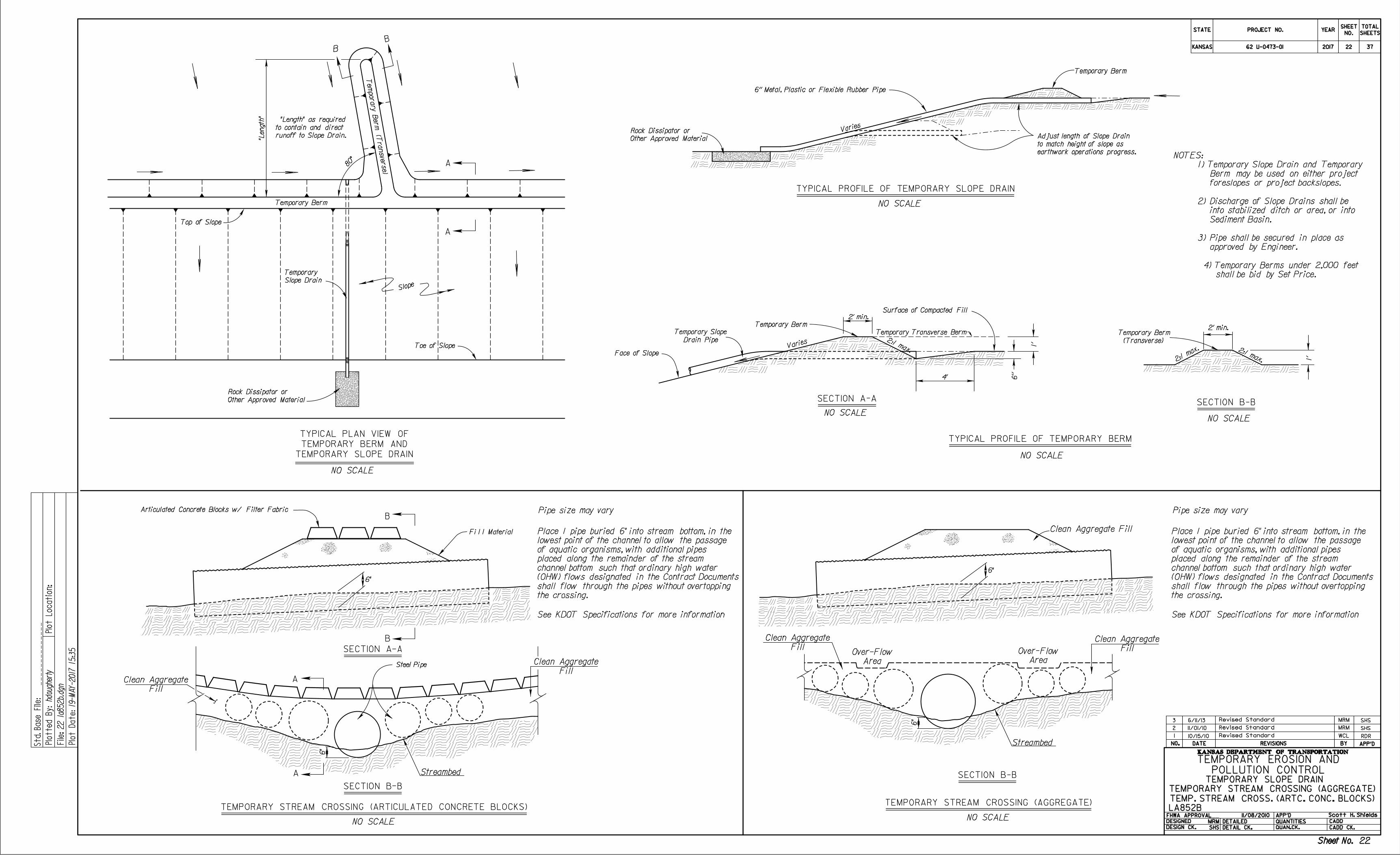
Pipe size may vary
SECTION B-B
NO SCALE
NO SCALENO SCALE
NO SCALE
SECTION A-A
Varies
Temporary Berm
Temporary Berm
2' min.
2:1 max.Vari
es
Face of Slope
Temporary Transverse BermÜ2' min.
2:1 max.2:1
max.
Surface of Compacted Fill
6''
1'
4'
1'
6'' Metal, Plastic or Flexible Rubber Pipe
TYPICAL PROFILE OF TEMPORARY SLOPE DRAIN
TYPICAL PROFILE OF TEMPORARY BERM
SECTION B-B
NO SCALE
TEMPORARY STREAM CROSSING (AGGREGATE)
B
B
Fi l l Material
Articulated Concrete Blocks w/ Filter Fabric
B
B
A
A
NO SCALE
Top of Slope
Temporary Berm
"Length"
80°
Te
mporary Ber
m (Transverse)
Slope
Toe of Slope
TEMPORARY STREAM CROSSING (AGGREGATE)
TEMP. STREAM CROSS. (ARTC. CONC. BLOCKS)
LA852B
STATE
KANSAS
PROJECT NO. YEARSHEET
NO.
TOTAL
SHEETS
KANSAS DEPARTMENT OF TRANSPORTATIONDATE REVISIONS BY APP'DNO.
DESIGNED
DESIGN CK.
DETAILED
DETAIL CK.
QUANTITIES
QUAN.CK.
APP'DFHWA APPROVAL
CADD
CADD CK.
Std.
Base
File:
22 la
852b.d
gn
19-
MA
Y-2017 15:3
5
hdougherty
Plotte
d
By:
File:
Plot
Locatio
n:
Plot
Date:
1 Revised Standard WCL RDR10/15/10
Scott H. Shields
POLLUTION CONTROL
TEMPORARY EROSION AND
Other Approved Material
Rock Dissipator or
earthwork operations progress.
to match height of slope as
Adjust length of Slope Drain
(Transverse)
Temporary Berm
Drain Pipe
Temporary Slope
runoff to Slope Drain.
to contain and direct
"Length" as required
Slope Drain
Temporary
Other Approved Material
Rock Dissipator or
TEMPORARY SLOPE DRAIN
TEMPORARY BERM AND
TYPICAL PLAN VIEW OF
Fill
Clean Aggregate
Area
Over-FlowFill
Clean Aggregate
Area
Over-Flow
A
SECTION A-A
SECTION B-B
Steel Pipe
A
NO SCALE
TEMPORARY STREAM CROSSING (ARTICULATED CONCRETE BLOCKS)
Fill
Clean Aggregate
Fill
Clean Aggregate
6"
6"
Streambed
6"
Streambed
6"
Revised Standard SHSMRM
Revised Standard6/11/13 SHSMRM
2
3
11/01/10
See KDOT Specifications for more informationSee KDOT Specifications for more information
Pipe size may vary
the crossing.
shall flow through the pipes without overtopping
(OHW) flows designated in the Contract Documents
channel bottom such that ordinary high water
placed along the remainder of the stream
of aquatic organisms, with additional pipes
lowest point of the channel to allow the passage
Place 1 pipe buried 6" into stream bottom, in the
11/08/2010
Sheet No.
TEMPORARY SLOPE DRAIN
MRM
SHS
Sheet No.
2017
shall be bid by Set Price.
4) Temporary Berms under 2,000 feet
approved by Engineer.
3) Pipe shall be secured in place as
Sediment Basin.
into stabilized ditch or area, or into
2) Discharge of Slope Drains shall be
foreslopes or project backslopes.
Berm may be used on either project
1) Temporary Slope Drain and Temporary
NOTES:
62 U-0473-01 22 37
22
NO SCALE
NO SCALE
CC
PLAN
AA
PLAN
SECTION A - A
SECTION B - B
SECTION C - C
for Stakes
4' maximum spacing
Cross Pieces ( see Notes )
Cross Pieces ( see Notes )
|nlet Grate
6''
6''
2' (min.)
2'
Stakes ( see Notes )
for Stakes
Main Flowline of Ditch
4' maximum spacing
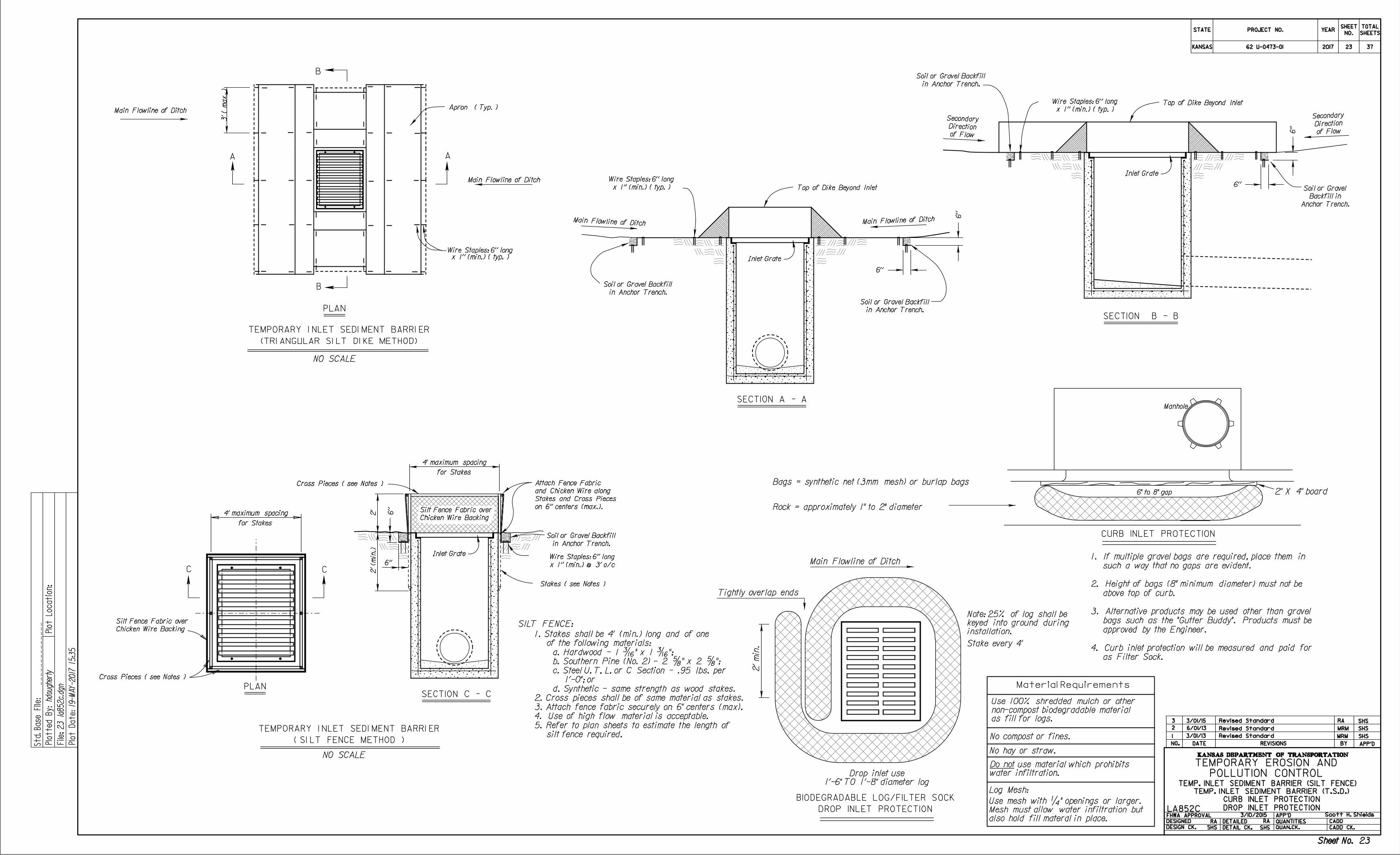
SILT FENCE:
B
B
Apron ( Typ. )
Main Flowline of Ditch
Main Flowline of Ditch Main Flowline of Ditch
|nlet Grate
|nlet Grate
6''
6''
Top of Dike Beyond Inlet
6''
6''
Top of Dike Beyond Inlet
3' (
max. )
1
MRM
Manhole
6" to 8" gap
MRM SHS
Rock = approximately 1" to 2" diameter
2" X 4" board
3/10/2015
STATE
KANSAS
PROJECT NO. YEARSHEET
NO.
TOTAL
SHEETS
KANSAS DEPARTMENT OF TRANSPORTATION
DATE REVISIONS BY APP'DNO.
DESIGNED
DESIGN CK.
DETAILED
DETAIL CK.
QUANTITIES
QUAN.CK.
APP'DFHWA APPROVAL
CADD
CADD CK.
Std.
Base
File:
23 la
852c.d
gn
19-
MA
Y-2017 15:3
5
hdougherty
Plotte
d
By:
File:
Plot
Locatio
n:
Plot
Date:
2
3
Scott H. Shields
Revised Standard
Revised Standard SHS
Revised Standard SHS
POLLUTION CONTROL
TEMPORARY EROSION AND
( SI LT FENCE METHOD )
TEMPORARY I NLET SEDI MENT BARRI ER
(TRI ANGULAR SI LT DI KE METHOD)
TEMPORARY I NLET SEDI MENT BARRI ER
CURB INLET PROTECTION
in Anchor Trench.
Soil or Gravel Backfill
Chicken Wire Backing
Silt Fence Fabric over
on 6'' centers (max.).
Stakes and Cross Pieces
and Chicken Wire along
Attach Fence Fabric
of Flow
Direction
Secondary
of Flow
Direction
Secondary
x 1'' (min.) ( typ. )
Wire Staples: 6'' long
x 1'' (min.) ( typ. )
Wire Staples: 6'' long
in Anchor Trench.
Soil or Gravel Backfill
in Anchor Trench.
Soil or Gravel Backfill
in Anchor Trench.
Soil or Gravel Backfill
Anchor Trench.
Backfill in
Soil or Gravel
Chicken Wire Backing
Silt Fence Fabric over
x 1'' (min.) ( typ. )Wire Staples: 6'' long
3/01/15
CURB INLET PROTECTION
DROP INLET PROTECTION
Material Requirements
as fill for logs.
non-compost biodegradable material
Use 100% shredded mulch or other
No compost or fines.
No hay or straw.
water infiltration.
Do not use material which prohibits
Log Mesh:
also hold fill materal in place.
Mesh must allow water infiltration but
Use mesh with ‚" openings or larger.
installation.
keyed into ground during
Note: 25% of log shall be
Tightly overlap ends
Bags = synthetic net (3mm mesh) or burlap bags
2'
min.
Main Flowline of Ditch
DROP INLET PROTECTION
BIODEGRADABLE LOG/FILTER SOCK
Stake every 4'
as Filter Sock.
4. Curb inlet protection will be measured and paid for
approved by the Engineer.
bags such as the "Gutter Buddy". Products must be
3. Alternative products may be used other than gravel
above top of curb.
2. Height of bags (8" minimum diameter) must not be
such a way that no gaps are evident.
1. If multiple gravel bags are required, place them in
3/01/13
1'-6" TO 1'-8" diameter log
Drop inlet use
Sheet No.
TEMP. INLET SEDIMENT BARRIER (SILT FENCE)
TEMP. INLET SEDIMENT BARRIER (T.S.D.)
LA852C
SHS SHS
Sheet No.
2017
silt fence required.
5. Refer to plan sheets to estimate the length of
4. Use of high flow material is acceptable.
3. Attach fence fabric securely on 6" centers (max).
2. Cross pieces shall be of same material as stakes.
d. Synthetic - same strength as wood stakes.
1'-0"; or
c. Steel U, T, L, or C Section - .95 lbs. per
b. Southern Pine (No. 2) - 2 †" x 2 †";
a. Hardwood - 1 ‰" x 1 ‰";
of the following materials:
1. Stakes shall be 4' (min.) long and of one
x 1'' (min.) @ 3' o/c
Wire Staples: 6'' long
6/01/13
RA
RARA
62 U-0473-01 23 37
23
B
B
A
A
TYPICAL ELEVATION
NO SCALE
Silt Fence Fabric
Silt Fence Fabric
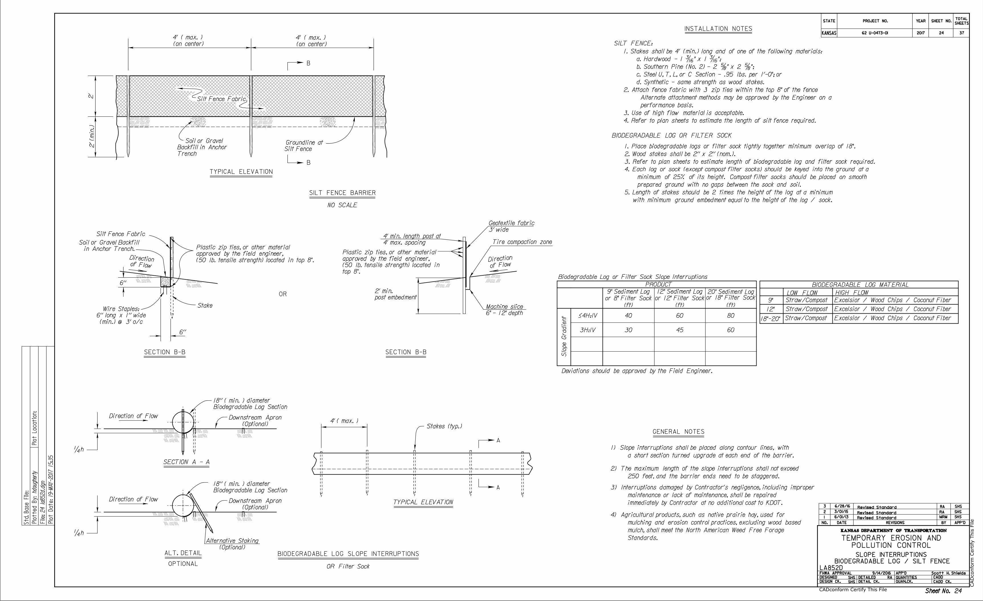
SILT FENCE:
GENERAL NOTES
Stake
TYPICAL ELEVATION
Stakes (typ.)
SECTION A - A
6''
6''
2'
2' (min.)
4' ( max. )
INSTALLATION NOTES
LA852D
MRM
PRODUCT
Slo
pe Gradie
nt ë4H:1V 40 60 80
3H:1V 30 45 60
9" Sediment Log 12" Sediment Log 20" Sediment Log
(ft) (ft) (ft)
9/14/2016
Scott H. Shields
POLLUTION CONTROL
TEMPORARY EROSION AND
SHS
SHS
of Flow
Direction
in Anchor Trench.
Soil or Gravel Backfill
(on center)
4' ( max. )
(on center)
4' ( max. )
Silt Fence
Groundline at
Trench
Backfill in Anchor
Soil or Gravel
(min.) @ 3' o/c
6'' long x 1'' wide
Wire Staples:
Revised Standard
BIODEGRADABLE LOG MATERIAL
9"
12"
LOW FLOW HIGH FLOW
Excelsior / Wood Chips / Coconut Fiber
Excelsior / Wood Chips / Coconut Fiber
Excelsior / Wood Chips / Coconut Fiber
Revised Standard
Standards.
mulch, shall meet the North American Weed Free Forage
mulching and erosion control practices, excluding wood based
4) Agricultural products, such as native prairie hay, used for
SECTION B-B SECTION B-B
of FlowDirection
3' wide
Geotextile fabric
Tire compaction zone
6" - 12" depth
Machine slice
post embedment
2' min.
4' max. spacing
4' min. length post at
OR
(50 lb. tensile strength) located in top 8".
approved by the field engineer,
Plastic zip ties, or other material
top 8".
(50 lb. tensile strength) located in
approved by the field engineer,
Plastic zip ties, or other material
3/01/15
18"-20"
Straw/Compost
Straw/Compost
Straw/Compost
KANSAS DEPARTMENT OF TRANSPORTATION
DATE REVISIONS BY APP'DNO.
DESIGNED
DESIGN CK.
DETAILED
DETAIL CK.
QUANTITIES
QUAN.CK.
APP'D
STATE PROJECT NO. YEARTOTAL
SHEETSSHEET NO.
FHWA APPROVAL
KANSAS
Std.
Base
File:
Plotte
d
By:
File:
Plot
Locatio
n:
Plot
Date:
24 la
852d.d
gn
19-
MA
Y-2017 15:3
5
hdougherty
CADD
CADD CK.
1
2
3
Sheet No.
SHS
Sheet No.
2017
RA
RA
6/01/13
4. Refer to plan sheets to estimate the length of silt fence required.
3. Use of high flow material is acceptable.
performance basis.
Alternate attachment methods may be approved by the Engineer on a
2. Attach fence fabric with 3 zip ties within the top 8" of the fence
d. Synthetic - same strength as wood stakes.
c. Steel U, T, L, or C Section - .95 lbs. per 1'-0"; or
b. Southern Pine (No. 2) - 2 †" x 2 †";
a. Hardwood - 1 ‰" x 1 ‰";
1. Stakes shall be 4' (min.) long and of one of the following materials:
Biodegradable Log or Filter Sock Slope Interruptions
Deviations should be approved by the Field Engineer.
a short section turned upgrade at each end of the barrier.
1) Slope interruptions shall be placed along contour lines, with
SHS
6/28/16 Revised Standard RA SHS
BIODEGRADABLE LOG SLOPE INTERRUPTIONS
250 feet, and the barrier ends need to be staggered.
2) The maximum length of the slope interruptions shall not exceed
immediately by Contractor at no additional cost to KDOT.
maintenance or lack of maintenance, shall be repaired
3) Interruptions damaged by Contractor's negligence, including improper
SILT FENCE BARRIER
Direction of Flow
Biodegradable Log Section
18'' ( min. ) diameter
(Optional)
Downstream Apron
Direction of Flow
(Optional)
Downstream Apron
(Optional)
Alternative Staking
Biodegradable Log Section
18'' ( min. ) diameter
ALT. DETAIL
OPTIONAL
‚h
‚h
OR Filter Sock
BIODEGRADABLE LOG OR FILTER SOCK
or 8" Filter Sock or 12" Filter Sockor 18" Filter Sock
SLOPE INTERRUPTIONS
BIODEGRADABLE LOG / SILT FENCE
with minimum ground embedment equal to the height of the log / sock.
5. Length of stakes should be 2 times the height of the log at a minimum
prepared ground with no gaps between the sock and soil.
minimum of 25% of its height. Compost filter socks should be placed on smooth
4. Each log or sock (except compost filter socks) should be keyed into the ground at a
3. Refer to plan sheets to estimate length of biodegradable log and filter sock required.
2. Wood stakes shall be 2'' x 2'' (nom.).
1. Place biodegradable logs or filter sock tightly together minimum overlap of 18".
CA
Dconform C
ertify T
his File
CADconform Certify This File
62 U-0473-01 24 37
24
1
NO SCALE
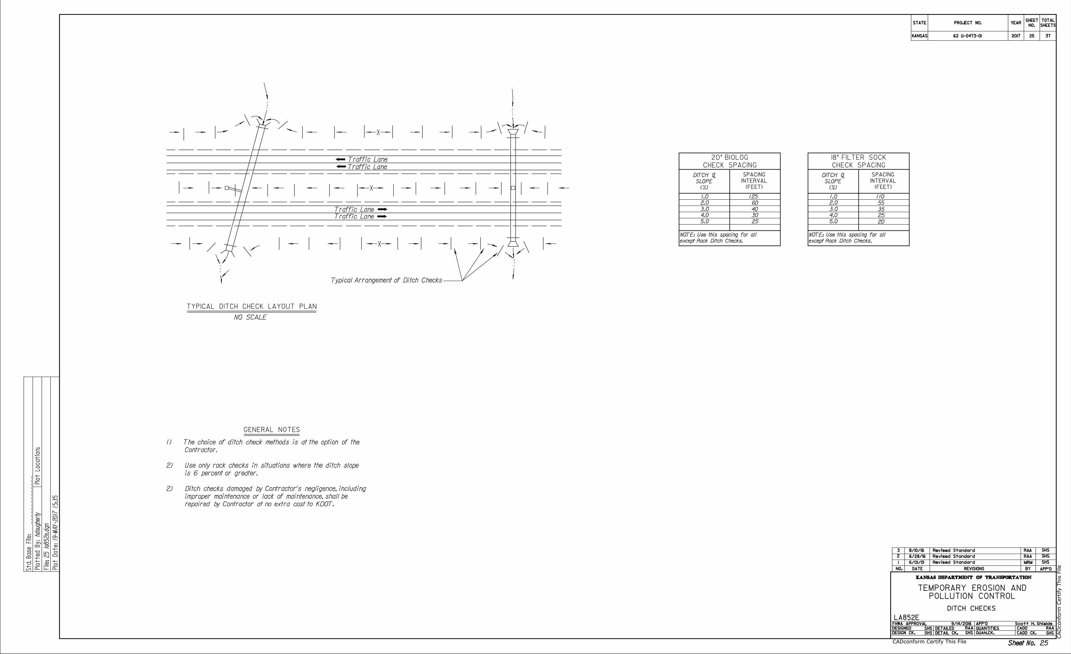
Traffic Lane
Traffic Lane
Traffic Lane
Traffic Lane
Typical Arrangement of Ditch Checks
TYPICAL DITCH CHECK LAYOUT PLAN
L
1.0
2.0
3.0
4.0
5.0
125
6/01/13 MRM
STATE
KANSAS
PROJECT NO. YEARSHEET
NO.
TOTAL
SHEETS
KANSAS DEPARTMENT OF TRANSPORTATION
DATE REVISIONS BY APP'DNO.
DESIGNED
DESIGN CK.
DETAILED
DETAIL CK.
QUANTITIES
QUAN.CK.
APP'DFHWA APPROVAL
CADD
CADD CK.
Std.
Base
File:
25 la
852e.d
gn
19-
MA
Y-2017 15:3
5
hdougherty
Plotte
d
By:
File:
Plot
Locatio
n:
Plot
Date:
2
3
Scott H. Shields9/14/2016
Revised Standard SHS
POLLUTION CONTROL
TEMPORARY EROSION AND
(%)
SLOPE
DITCH C
(FEET)
INTERVAL
SPACING
GENERAL NOTES
DITCH CHECKS
Sheet No.
LA852E
SHS
SHS SHS
RAA
SHS
RAA
Sheet No.
2017
except Rock Ditch Checks.
NOTE: Use this spacing for all
Revised Standard RAA SHS
25
L
1.0
2.0
3.0
4.0
5.0
(%)
SLOPE
DITCH C
(FEET)
INTERVAL
SPACING
except Rock Ditch Checks.
NOTE: Use this spacing for all
20
CHECK SPACING
18" FILTER SOCK
60
40
30
110
55
35
25
CHECK SPACING
20" BIOLOG
Revised Standard RAA SHS
6/28/16
repaired by Contractor at no extra cost to KDOT.
improper maintenance or lack of maintenance, shall be
2) Ditch checks damaged by Contractor's negligence, including
is 6 percent or greater.
2) Use only rock checks in situations where the ditch slope
Contractor.
1) The choice of ditch check methods is at the option of the
8/10/16
CA
Dconform C
ertify T
his File
CADconform Certify This File
62 U-0473-01 25 37
25
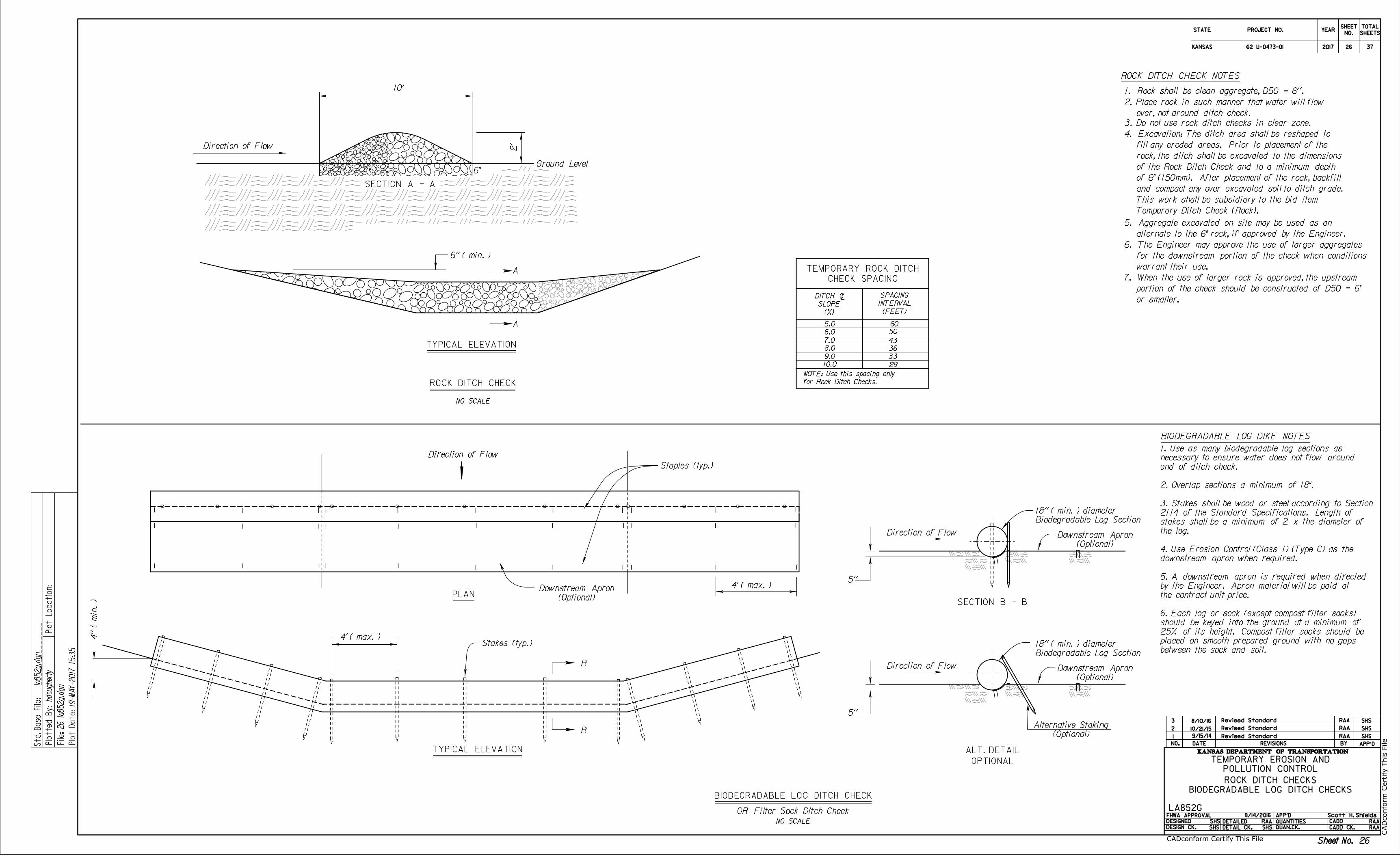
ROCK DITCH CHECK NOTES
1. Rock shall be clean aggregate, D50 = 6''.
6"Ground Level
la852g.d
gn
NO SCALE
NO SCALE
L
5''
5.0
6.0
7.0
8.0
9.0
10.0
50
43
36
33
29
60
Direction of Flow
TYPICAL ELEVATION
SECTION B - BPLAN
TYPICAL ELEVATION
SECTION A - A
Direction of Flow
B
B
A
A
Staples (typ.)
ROCK DITCH CHECK
Direction of Flow
BIODEGRADABLE LOG DIKE NOTES
Stakes (typ.)
4' ( max. )
4' ( max. )
3. Do not use rock ditch checks in clear zone.
6'' ( min. )
2'
10'
BIODEGRADABLE LOG DITCH CHECK
4'' ( min. )
9/14/2016 Scott H. Shields
ROCK DITCH CHECKS
BIODEGRADABLE LOG DITCH CHECKS
LA852G
Revised Standard SHS
STATE
KANSAS
PROJECT NO. YEARSHEET
NO.
TOTAL
SHEETS
KANSAS DEPARTMENT OF TRANSPORTATIONDATE REVISIONS BY APP'DNO.
DESIGNED
DESIGN CK.
DETAILED
DETAIL CK.
QUANTITIES
QUAN.CK.
APP'DFHWA APPROVAL
CADD
CADD CK.
Std.
Base
File:
26 la
852g.d
gn
19-
MA
Y-2017 15:3
5
hdougherty
Plotte
d
By:
File:
Plot
Locatio
n:
Plot
Date:
POLLUTION CONTROL
TEMPORARY EROSION AND
(%)
SLOPE
DITCH C
(FEET)
INTERVAL
SPACING
for Rock Ditch Checks.
NOTE: Use this spacing only
Biodegradable Log Section
18'' ( min. ) diameter
CHECK SPACING
TEMPORARY ROCK DITCH
10/21/15 Revised Standard SHS
Sheet No.
SHS SHS
2
1
Sheet No.
2017
(Optional)
Downstream Apron
(Optional)
Downstream Apron
OR Filter Sock Ditch Check
3
RAA
RAA RAA
Temporary Ditch Check (Rock).
This work shall be subsidiary to the bid item
and compact any over excavated soil to ditch grade.
of 6" (150mm). After placement of the rock, backfill
of the Rock Ditch Check and to a minimum depth
rock, the ditch shall be excavated to the dimensions
fill any eroded areas. Prior to placement of the
4. Excavation: The ditch area shall be reshaped to
RAA
9/15/14 RAA
SHS
over, not around ditch check.
2. Place rock in such manner that water will flow
8/10/16 Revised Standard SHSRAA
warrant their use.
for the downstream portion of the check when conditions
6. The Engineer may approve the use of larger aggregates
alternate to the 6" rock, if approved by the Engineer.
5. Aggregate excavated on site may be used as an
or smaller.
portion of the check should be constructed of D50 = 6"
7. When the use of larger rock is approved, the upstream
5''
Direction of Flow
(Optional)
Downstream Apron
(Optional)
Alternative Staking
Biodegradable Log Section
18'' ( min. ) diameter
ALT. DETAIL
OPTIONAL
between the sock and soil.
placed on smooth prepared ground with no gaps
25% of its height. Compost filter socks should be
should be keyed into the ground at a minimum of
6. Each log or sock (except compost filter socks)
the contract unit price.
by the Engineer. Apron material will be paid at
5. A downstream apron is required when directed
downstream apron when required.
4. Use Erosion Control (Class 1) (Type C) as the
the log.
stakes shall be a minimum of 2 x the diameter of
2114 of the Standard Specifications. Length of
3. Stakes shall be wood or steel according to Section
2. Overlap sections a minimum of 18".
end of ditch check.
necessary to ensure water does not flow around
1. Use as many biodegradable log sections as
CA
Dconform C
ertify T
his File
CADconform Certify This File
62 U-0473-01 26 37
26
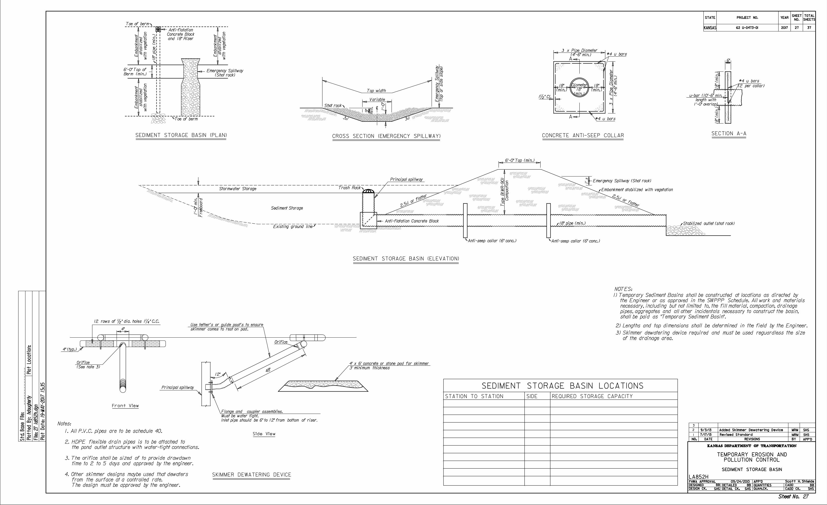
POLLUTION CONTROL
TEMPORARY EROSION AND
LA852H
2.5:1
or flatter 2.5:1 or flatter
6'-0" Top (min.)
ÚEmbankment stabilized with vegetation
1' á
Existing ground lineÛ
Stormwater Storage
Sediment Storage
Trash RackÜ
1'-
0"
min.
Freeboard
Ú18" pipe (min.)
2) Lengths and top dimensions shall be determined in the field by the Engineer.
NOTES:
Emergency Spillway (Shot rock)
ÚStabilized outlet (shot rock)Anti-flotation Concrete Block
SEDIMENT STORAGE BASIN (ELEVATION)
SEDIMENT STORAGE BASIN (PLAN)
Ú18" pip
e (min.)
Toe of bermÜ
ÙToe of berm
CROSS SECTION (EMERGENCY SPILLWAY)
9"
min.
Top width
Variable
1'-
0"
ìShot rockÜ
3:1 3:1
ÙAnti-seep collar (6" conc.) ÙAnti-seep collar (6" conc.)
Diameter
A
A#4 u bars
#4 u bars
1•" Cl.
CONCRETE ANTI-SEEP COLLARSECTION A-A
#4 u bars
6"
18" (min.)
18" (min.)
(2 per collar)
BB BB BB
shall be paid as "Temporary Sediment Basin".
pipes, aggregates and all other incidentals necessary to construct the basin,
necessary, including but not limited to, the fill material, compaction, drainage
the Engineer or as approved in the SWPPP Schedule. All work and materials
1) Temporary Sediment Basins shall be constructed at locations as directed by
STATE
KANSAS
PROJECT NO. YEARSHEET
NO.
TOTAL
SHEETS
KANSAS DEPARTMENT OF TRANSPORTATION
DATE REVISIONS BY APP'DNO.
DESIGNED
DESIGN CK.
DETAILED
DETAIL CK.
QUANTITIES
QUAN.CK.
APP'DFHWA APPROVAL
CADD
CADD CK.
Std.
Base
File:
27 la
852h.d
gn
19-
MA
Y-2017 15:3
5
hdougherty
Plotte
d
By:
File:
Plot
Locatio
n:
Plot
Date:
NO.
1
2
3
SHS SHS SHS
(4'-6" min.)
3 x Pipe Diameter
(4'-
6"
min.)
3 x Pip
e Dia
meter
Co
mpaction
Type B(M
R-90)
Berm (min.)
6'-0" Top of
(Shot rock)
Emergency Spillway
with vegetation
sta
biliz
ed
Em
bank
ment
with vegetation
sta
biliz
ed
Em
bank
ment
with vegetation
sta
biliz
ed
Em
bank
ment
and 18" Riser
Concrete Block
Anti-flotation
(top or sid
e slo
pe)
Emergency Spillw
ay
1'-0" overlap)
length with
u-bar (10'-6" min.
(min.)
18"
(min.)
18"
(min.)
18"
SEDIMENT STORAGE BASIN
SEDIMENT STORAGE BASIN LOCATIONS
STATION TO STATION SIDE REQUIRED STORAGE CAPACITY
09/24/2013
Sheet No.
Scott H. Shields
Sheet No.
2017
7/17/13 Revised Standard MRM SHS
12 rows of •" dia. holes 1‚" C.C.
3' minimum thickness
4' x 6' concrete or stone pad for skimmer
Notes:
Front View
Side View
SKIMMER DEWATERING DEVICE
4"
12"48"
Principal spillway
Principal spillway
Orifice
MRM SHS9/3/13 Added Skimmer Dewatering Device
(See note 3)
Orifice
4" (typ.)
Inlet pipe should be 6" to 12" from bottom of riser.
Must be water tight.
Flange and coupler assemblies.
skimmer comes to rest on pad.
Use tether's or guide post's to ensure
The design must be approved by the engineer.
from the surface at a controlled rate.
4. Other skimmer designs maybe used that dewaters
time to 2 to 5 days and approved by the engineer.
3. The orifice shall be sized of to provide drawdown
the pond outlet structure with water-tight connections.
2. HDPE flexible drain pipes is to be attached to
1. All P.V.C. pipes are to be schedule 40.
of the drainage area.
3) Skimmer dewatering device required and must be used reguardless the size
62 U-0473-01 27 37
27
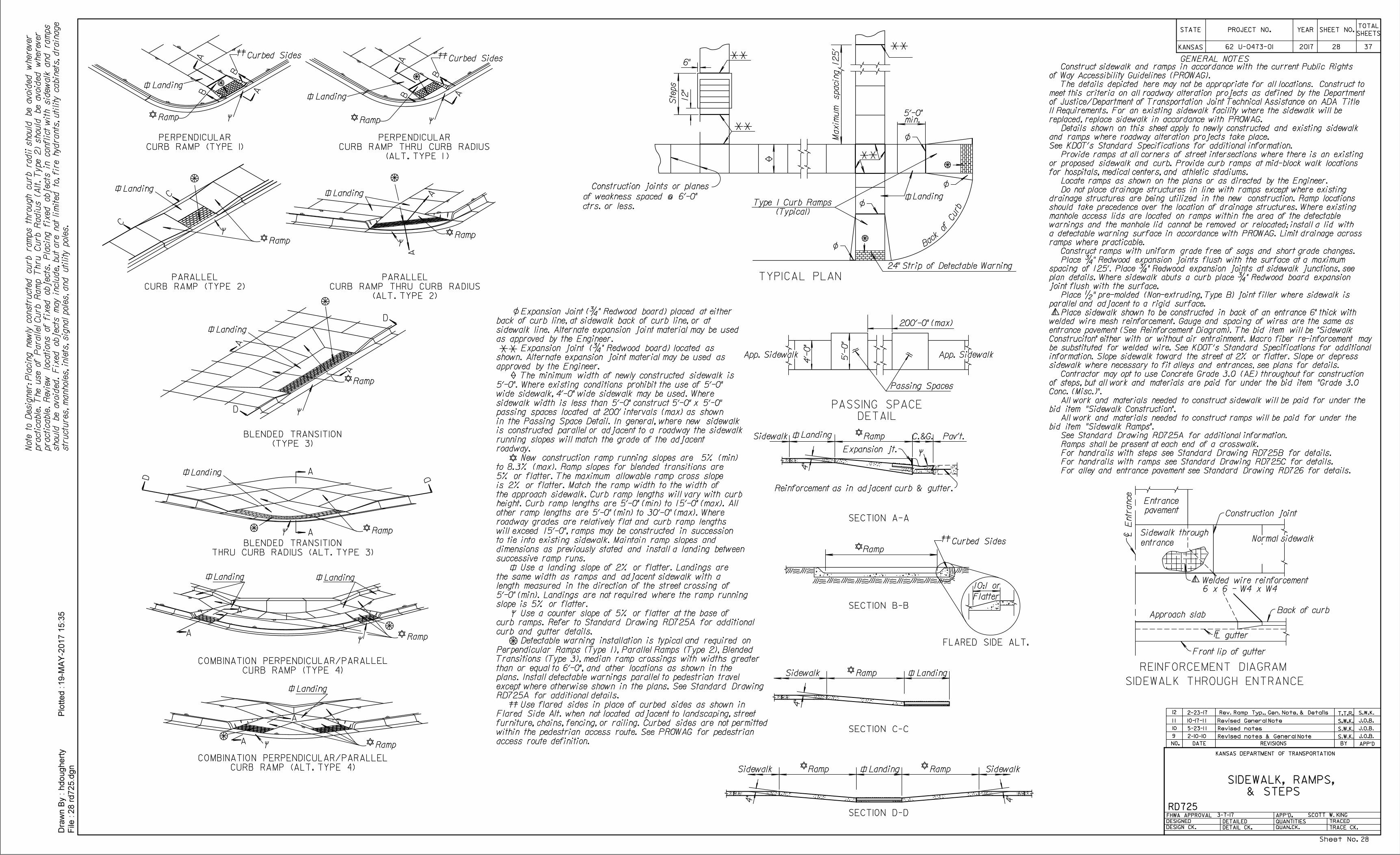
24" Strip of Detectable Warning
REINFORCEMENT DIAGRAM
6"GENERAL NOTES
Construction joints or planes
of weakness spaced @ 6'-0"
ctrs. or less.
Ste
ps
12"
L E
ntr
ance
c Sidewalk through
entrance
Approach slabBack of curb
L gutterF
Front lip of gutter
Entrance
pavement Construction joint
Normal sidewalk
Landing
5'-0"min.
Landing
Welded wire reinforcement
6 x 6 - W4 x W4
TYPICAL PLAN
SIDEWALK THROUGH ENTRANCE
2-10-10 S.W.K. J.O.B.
S.W.K. J.O.B.
S.W.K. J.O.B.
T.T.R. S.W.K.
Revised notes & General Note
5-23-1 1 Revised notes
10-17-1 1 Revised General Note
A
A
C.&G.RampSidewalk Pav't.
4"
Expansion jt.
Landing
Reinforcement as in adjacent curb & gutter.
SECTION A-A
10:1 or
Flatter
SECTION B-B
B
B
Curbed Sides
Ramp
Landing
C
C
RampSidewalk
4"
Landing
SECTION C-C
Curbed Sides
RampSidewalk
4"
Landing
SECTION D-D
Ramp Sidewalk
4"
Ramp
Ramp
FLARED SIDE ALT.
br
uC fo
kcaB
Ramp
Landing
Ramp
Landing
A
A
A
A
D
D
D D
1 1
10
9
STATE
KANSAS
YEARPROJECT N0.SHEETS
TOTALSHEET NO.
28 rd725.d
gn
File :
Dra
wn B
y :
hdougherty
Plotted :19-M
AY-2
017 1
5:3
5
DATE REVISIONS BY APP'DNO.
KANSAS DEPARTMENT OF TRANSPORTATION
& STEPS
SIDEWALK, RAMPS,
FHWA APPROVAL
DESIGNED
DETAILED
DESIGN CK. DETAIL CK. QUAN.CK.
RD725
TRACED
TRACE CK.
QUANTITIES
APP'D.
12 2-23-17 Rev. Ramp Typ., Gen. Note, & Details
Landing
Ramp
A
A
Ramp
Landing Landing
A
A
Landing
A
A
B
B
Curbed Sides
Ramp
SCOTT W. KING
Maxim
um spacin
g 125'
DETAIL
PASSING SPACE
200'-0" (max)
4'-
0"
5'-
0"
CURB RAMP (TYPE I)
PERPENDICULAR
(ALT. TYPE I )
CURB RAMP THRU CURB RADIUS
PERPENDICULAR
CURB RAMP (TYPE 2)
PARALLEL
(TYPE 3)
BLENDED TRANSITION
THRU CURB RADIUS (ALT. TYPE 3)
BLENDED TRANSITION
CURB RAMP (TYPE 4)
COMBINATION PERPENDICULAR/PARALLEL
CURB RAMP (ALT. TYPE 4)
COMBINATION PERPENDICULAR/PARALLEL
(ALT. TYPE 2)
CURB RAMP THRU CURB RADIUS
PARALLEL
(Typical)
Type 1 Curb Ramps
Landing
A
A
Ramp
Passing Spaces
App. SidewalkApp. Sidewalk
str
uctures,
manholes, inlets, sig
nal poles, and utility poles.
should be avoid
ed.
Fix
ed objects
may in
clu
de, but are not li
mited to, fire hydrants, utility cabin
ets, drain
age
practicable.
Revie
w locations of fix
ed objects.
Pla
cin
g fix
ed objects in conflict
with sid
ewalk and ra
mps
practicable.
The use of Parallel
Curb Ra
mp Thru
Curb Radius (Alt.
Type 2) should be avoid
ed
wherever
Note to Desig
ner: Pla
cin
g newly constr
ucte
d curb ra
mps through curb radii s
hould be avoid
ed
wherever
For alley and entrance pavement see Standard Drawing RD726 for details.
For handrails with ramps see Standard Drawing RD725C for details.
For handrails with steps see Standard Drawing RD725B for details.
Ramps shall be present at each end of a crosswalk.
See Standard Drawing RD725A for additional information.
bid item "Sidewalk Ramps".
All work and materials needed to construct ramps will be paid for under the
bid item "Sidewalk Construction".
All work and materials needed to construct sidewalk will be paid for under the
Conc. (Misc.)".
of steps, but all work and materials are paid for under the bid item "Grade 3.0
Contractor may opt to use Concrete Grade 3.0 (AE) throughout for construction
sidewalk where necessary to fit alleys and entrances, see plans for details.
information. Slope sidewalk toward the street at 2% or flatter. Slope or depress
be substituted for welded wire. See KDOT's Standard Specifications for additional
Construciton" either with or without air entrainment. Macro fiber re-inforcement may
entrance pavement (See Reinforcement Diagram). The bid item will be "Sidewalk
welded wire mesh reinforcement. Gauge and spacing of wires are the same as
Place sidewalk shown to be constructed in back of an entrance 6" thick with
parallel and adjacent to a rigid surface.
Place •" pre-molded (Non-extruding, Type B) joint filler where sidewalk is
joint flush with the surface.
plan details. Where sidewalk abuts a curb place ƒ" Redwood board expansion
spacing of 125'. Place ƒ" Redwood expansion joints at sidewalk junctions, see
Place ƒ" Redwood expansion joints flush with the surface at a maximum
Construct ramps with uniform grade free of sags and short grade changes.
ramps where practicable.
a detectable warning surface in accordance with PROWAG. Limit drainage across
warnings and the manhole lid cannot be removed or relocated; install a lid with
manhole access lids are located on ramps within the area of the detectable
should take precedence over the location of drainage structures. Where existing
drainage structures are being utilized in the new construction. Ramp locations
Do not place drainage structures in line with ramps except where existing
Locate ramps as shown on the plans or as directed by the Engineer.
for hospitals, medical centers, and athletic stadiums.
or proposed sidewalk and curb. Provide curb ramps at mid-block walk locations
Provide ramps at all corners of street intersections where there is an existing
See KDOT's Standard Specifications for additional information.
and ramps where roadway alteration projects take place.
Details shown on this sheet apply to newly constructed and existing sidewalk
replaced, replace sidewalk in accordance with PROWAG.
II Requirements. For an existing sidewalk facility where the sidewalk will be
of Justice/Department of Transportation Joint Technical Assistance on ADA Title
meet this criteria on all roadway alteration projects as defined by the Department
The details depicted here may not be appropriate for all locations. Construct to
of Way Accessibility Guidelines (PROWAG).
Construct sidewalk and ramps in accordance with the current Public Rights
access route definition.
within the pedestrian access route. See PROWAG for pedestrian
furniture, chains, fencing, or railing. Curbed sides are not permitted
Flared Side Alt. when not located adjacent to landscaping, street
Use flared sides in place of curbed sides as shown in
RD725A for additional details.
except where otherwise shown in the plans. See Standard Drawing
plans. Install detectable warnings parallel to pedestrian travel
than or equal to 6'-0", and other locations as shown in the
Transitions (Type 3), median ramp crossings with widths greater
Perpendicular Ramps (Type 1), Parallel Ramps (Type 2), Blended
Detectable warning installation is typical and required on
curb and gutter details.
curb ramps. Refer to Standard Drawing RD725A for additional
Use a counter slope of 5% or flatter at the base of
slope is 5% or flatter.
5'-0" (min). Landings are not required where the ramp running
length measured in the direction of the street crossing of
the same width as ramps and adjacent sidewalk with a
Use a landing slope of 2% or flatter. Landings are
successive ramp runs.
dimensions as previously stated and install a landing between
to tie into existing sidewalk. Maintain ramp slopes and
will exceed 15'-0", ramps may be constructed in succession
roadway grades are relatively flat and curb ramp lengths
other ramp lengths are 5'-0" (min) to 30'-0" (max). Where
height. Curb ramp lengths are 5'-0" (min) to 15'-0" (max). All
the approach sidewalk. Curb ramp lengths will vary with curb
is 2% or flatter. Match the ramp width to the width of
5% or flatter. The maximum allowable ramp cross slope
to 8.3% (max). Ramp slopes for blended transitions are
New construction ramp running slopes are 5% (min)
roadway.
running slopes will match the grade of the adjacent
is constructed parallel or adjacent to a roadway the sidewalk
in the Passing Space Detail. In general, where new sidewalk
passing spaces located at 200' intervals (max) as shown
sidewalk width is less than 5'-0" construct 5'-0" x 5'-0"
wide sidewalk, 4'-0" wide sidewalk may be used. Where
5'-0". Where existing conditions prohibit the use of 5'-0"
The minimum width of newly constructed sidewalk is
approved by the Engineer.
shown. Alternate expansion joint material may be used as
Expansion joint (ƒ" Redwood board) located as
as approved by the Engineer.
sidewalk line. Alternate expansion joint material may be used
back of curb line, at sidewalk back of curb line, or at
Expansion Joint (ƒ" Redwood board) placed at either
3-7-17
62 U-0473-01 2017 28 37
Sheet No. 28
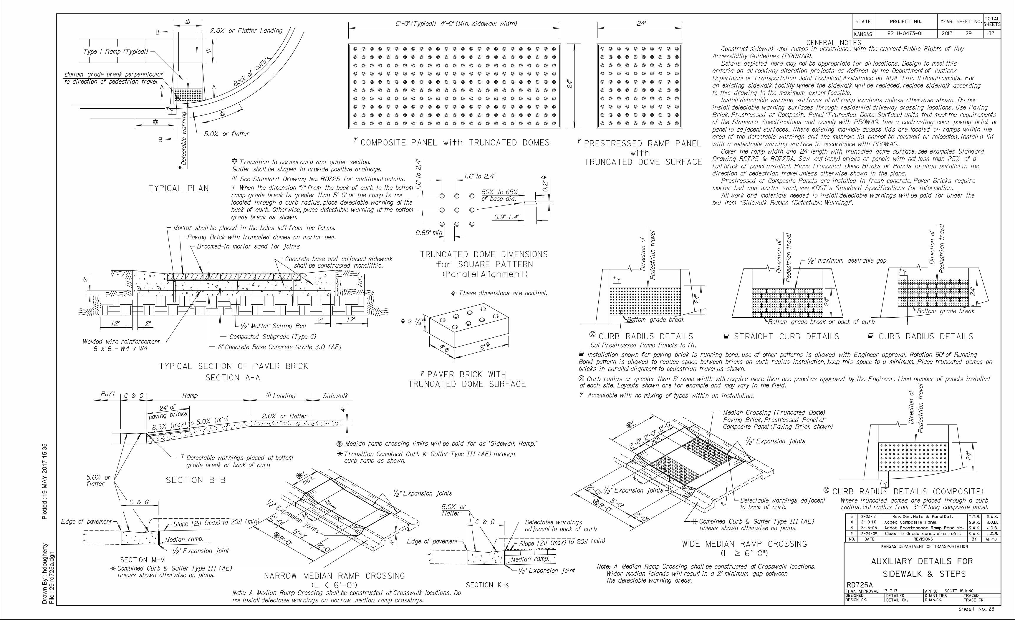
S.W.K. J.O.B.2
3 S.W.K. J.O.B.
2-24-05 Class to Grade conc., wire reinf.
S.W.K. J.O.B.
8-1 5-05 Added Prestressed Ramp Panel alt.
2'-0"
2'-0"
5'-0"
4"
C & G
2"2"
Pav't C & G Ramp Sidewalk
2'-0"
2'-0"
5'-0" 4"
2'-0"
2'-0"
9'-0"
9'-0"
Landing
2"
4"
Var.
max.
12"12"
24" of
paving bricks
8"4"
2 ‚"
0.2
"
0.9"-1.4"
0.65" min
of base dia.
50% to 65%
1.6
" to 2.4
"
1.6" to 2.4"
•" Expansion joints
•" Expansion joints
Combined Curb & Gutter Type ||| (AE)
Edge of pavement
•" Expansion joint
unless shown otherwise on plans.
Compacted Subgrade (Type C)
Broomed-in mortar sand for joints
•" Expansion joints
•" Expansion joints
Combined Curb & Gutter Type ||| (AE)
unless shown otherwise on plans.
flatter
Mortar shall be placed in the holes left from the forms.
to back of curb.
Detectable warnings adjacent
•" Mortar Setting Bed
Paving Brick with truncated domes on mortar bed.
Concrete base and adjacent sidewalk
shall be constructed monolithic.„" maximum desirable gap D
irection of
Pedestria
n tr
avel
6" Concrete Base Concrete Grade 3.0 (AE)Welded wire reinforcement
6 x 6 - W4 x W4
Median ramp
Note: A Median Ramp Crossing shall be constructed at Crosswalk locations.
Median ramp crossing limits will be paid for as "Sidewalk Ramp."
These dimensions are nominal.
SECTION M-M
M
K
K
M
GENERAL NOTES
TYPICAL PLAN
TYPICAL SECTION OF PAVER BRICK
SECTION A-A
SECTION B-B
CURB RADIUS DETAILSSTRAIGHT CURB DETAILS
PAVER BRICK WITH
TRUNCATED DOME SURFACE
TRUNCATED DOME DIMENSIONS
for SQUARE PATTERN
(Parallel Alignment)
PRESTRESSED RAMP PANEL
with
TRUNCATED DOME SURFACE
24"
24"
Acceptable with no mixing of types within an installation.
COMPOSITE PANEL with TRUNCATED DOMES
Back
ofcu
rbÜ
Type 1 Ramp (Typical)
5.0% or flatter
A
B
A
B
Dete
cta
ble warnin
g
Transition to normal curb and gutter section.
See Standard Drawing No. RD725 for additional details.
Gutter shall be shaped to provide positive drainage.
Pedestria
n tr
avel
Direction of
Direction of
Pedestria
n tr
avel
CURB RADIUS DETAILS (COMPOSITE)
24"
Median Crossing (Truncated Dome)
Paving Brick, Prestressed Panel or
Composite Panel (Paving Brick shown)
2'-0"
min.
CURB RADIUS DETAILS
Direction of
Pedestria
n tr
avel
Installation shown for paving brick is running bond, use of other patterns is allowed with Engineer approval. Rotation 90° of Running
bricks in parallel alignment to pedestrian travel as shown.
24"
24"
24"
5'-0" (Typical) 4'-0" (Min. sidewalk width)
Cut Prestressed Ramp Panels to fit.
at each site. Layouts shown are for example and may vary in the field.
4
T.T.R. S.W.K.
2-1 0-1 0 Added Composite Panel
STATE
KANSAS
YEARPROJECT N0.SHEETS
TOTALSHEET NO.
29 rd725a.d
gn
File :
Dra
wn B
y :
hdougherty
Plotted :19-M
AY-2
017 1
5:3
5
DATE REVISIONS BY APP'DNO.
KANSAS DEPARTMENT OF TRANSPORTATION
AUXILIARY DETAILS FOR
SIDEWALK & STEPS
FHWA APPROVAL
DESIGNED
DETAILED
DESIGN CK. DETAIL CK. QUAN.CK.
RD725A
TRACED
TRACE CK.
QUANTITIES
APP'D.
C & G
Edge of pavement
•" Expansion joint
adjacent to back of curb
Detectable warnings
Median ramp
SECTION K-K
L
L
(L ï 6'-0")
WIDE MEDIAN RAMP CROSSING
(L < 6'-0")
NARROW MEDIAN RAMP CROSSING
Slope 12:1 (max) to 20:1 (min)
Slope 12:1 (max) to 20:1 (min)
not install detectable warnings on narrow median ramp crossings.
Note: A Median Ramp Crossing shall be constructed at Crosswalk locations. Do
the detectable warning areas.
Wider median islands will result in a 2' minimum gap between
to direction of pedestrian travel
Bottom grade break perpendicular
grade break or back of curb
Detectable warnings placed at bottom
ÙBottom grade break or back of curbÙBottom grade break
ÙBottom grade break
5.0% or
2.0% or flatter
8.3% (max) to 5.0
% (min)
2.0% or Flatter Landing
5 2-23-17 Rev. Gen. Note & Panel Det.
curb ramp as shown.
Transition Combined Curb & Gutter Type ||| (AE) through
Y
Y
Y
Y
SCOTT W. KING
Bond pattern is allowed to reduce space between bricks on curb radius installation, keep this space to a minimum. Place truncated domes on
Curb radius or greater than 5' ramp width will require more than one panel as approved by the Engineer. Limit number of panels installed
grade break as shown.
back of curb. Otherwise, place detectable warning at the bottom
located through a curb radius, place detectable warning at the
ramp grade break is greater than 5'-0" or the ramp is not
When the dimension "Y" from the back of curb to the bottom
radius, cut radius from 3'-0" long composite panel.
Where truncated domes are placed through a curb
bid item "Sidewalk Ramps (Detectable Warning)".
All work and materials needed to install detectable warnings will be paid for under the
mortar bed and mortar sand, see KDOT's Standard Specifications for information.
Prestressed or Composite Panels are installed in fresh concrete, Paver Bricks require
direction of pedestrian travel unless otherwise shown in the plans.
full brick or panel installed. Place Truncated Dome Bricks or Panels to align parallel in the
Drawing RD725 & RD725A. Saw cut (only) bricks or panels with not less than 25% of a
Cover the ramp width and 24" length with truncated dome surface, see examples Standard
with a detectable warning surface in accordance with PROWAG.
area of the detectable warnings and the manhole lid cannot be removed or relocated, install a lid
panel to adjacent surfaces. Where existing manhole access lids are located on ramps within the
of the Standard Specifications and comply with PROWAG. Use a contrasting color paving brick or
Brick, Prestressed or Composite Panel (Truncated Dome Surface) units that meet the requirements
install detectable warning surfaces through residential driveway crossing locations. Use Paving
Install detectable warning surfaces at all ramp locations unless otherwise shown. Do not
to this drawing to the maximum extent feasible.
an existing sidewalk facility where the sidewalk will be replaced, replace sidewalk according
Department of Transportation Joint Technical Assistance on ADA Title II Requirements. For
criteria on all roadway alteration projects as defined by the Department of Justice/
Details depicted here may not be appropriate for all locations. Design to meet this
Accessibility Guidelines (PROWAG).
Construct sidewalk and ramps in accordance with the current Public Rights of Way
3-7-17
flatter
5.0% or
62 U-0473-01 2017 29 37
Sheet No. 29
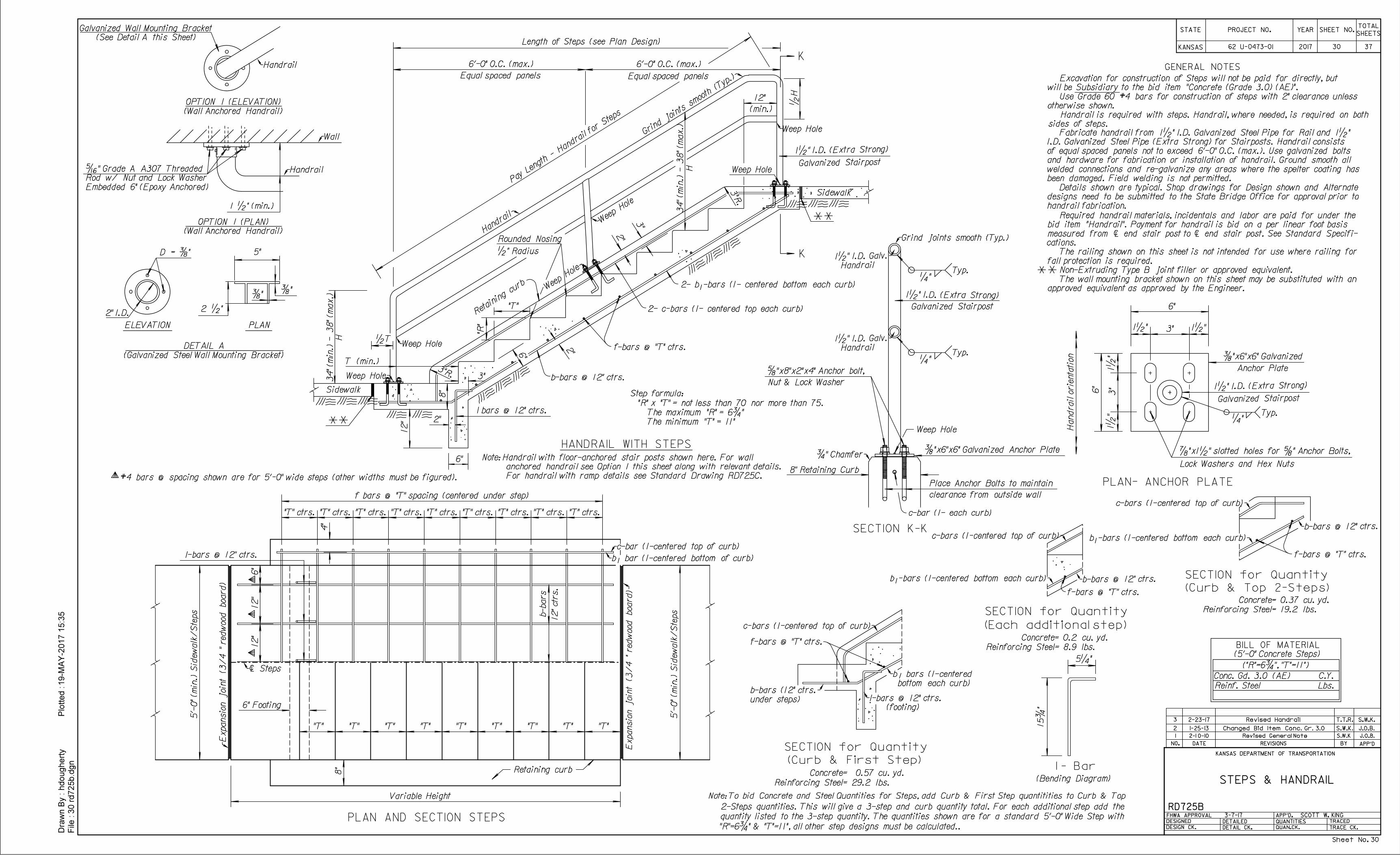
6"
1•
"
Anchor Plate
‚"
PLAN- ANCHOR PLATE
Typ.
Weep Hole
Handrail
1•" I.D. Galv.Û
Typ.‚"
1•" I.D. (Extra Strong)
Galvanized Stairpost
1•
"3"
6"
3"1•" 1•"
1•" I.D. (Extra Strong)
Galvanized Stairpost
SECTION K-K
8" Retaining Curb
ÚGrind joints smooth (Typ.)
Place Anchor Bolts to maintain
clearance from outside wall
†"x8"x2"x4" Anchor bolt,
Nut & Lock Washer
…"x6"x6" Galvanized
…"x6"x6" Galvanized Anchor Plate
Lock Washers and Hex Nuts
GENERAL NOTES
5'-
0" (min.) Sid
ewalk/
Ste
ps
5'-
0" (min.) Sid
ewalk/
Ste
ps
PLAN AND SECTION STEPS
8"
6" Footing
ÚE
xpansio
n joint (3/4 " red
wood board)
Expansio
n joint (3/4 " red
wood board)Û
4"
"T" ctrs. "T" ctrs. "T" ctrs. "T" ctrs. "T" ctrs. "T" ctrs. "T" ctrs. "T" ctrs. "T" ctrs.
Variable Height
6"
12"
12"
Ùì Steps
Retaining curb
#4 bars @ spacing shown are for 5'-0" wide steps (other widths must be figured).
designs need to be submitted to the State Bridge Office for approval prior to
handrail fabrication.
b-bars
Ùb bar (1-centered bottom of curb)Ó
Úc-bar (1-centered top of curb)
(Curb & First Step)
SECTION for Quantity
SECTION for Quantity
SECTION for Quantity
(Each additional step)
(Curb & Top 2-Steps)
c-bars (1-centered top of curb)Ü
Ó
under steps)
b-bars (12" ctrs.Û
5‚"
15ƒ
" (footing)
Ùl-bars @ 12" ctrs.
f bars @ "T" spacing (centered under step)
l-bars @ 12" ctrs.
l - Bar
bottom each curb)
Ùb bars (1-centered
f-bars @ "T" ctrs.
f-bars @ "T" ctrs.
c-bar (1- each curb)
Ób -bars (1-centered bottom each curb)Ü
c-bars (1-centered top of curb)Ü
c-bars (1-centered top of curb)Ü
f-bars @ "T" ctrs.
Ób -bars (1-centered bottom each curb)Ü Ùb-bars @ 12" ctrs.
12" ctrs.
Ùb-bars @ 12" ctrs.
Concrete= 0.37 cu. yd.
Reinforcing Steel= 19.2 lbs.
Concrete= 0.2 cu. yd.
Reinforcing Steel= 8.9 lbs.(5'-0" Concrete Steps)
(Bending Diagram)
("R"=6ƒ", "T"=11")
Reinf. Steel Lbs.
Note: To bid Concrete and Steel Quantities for Steps, add Curb & First Step quantitities to Curb & Top
Retaining curb
6'-0" O.C. (max.)
Equal spaced panels
3"
12"
(min.)
Weep HoleÜ
1•" I.D. (Extra Strong)
Galvanized StairpostWeep Hole
8"
6'-0" O.C. (max.)
Equal spaced panels
2"
Weep H
oleÜ
Sidewalk
Sidewalk
Pay
Length - H
andrail f
or Steps
HandrailÜ
K
K
Grind joints s
mooth (
Typ.)Ü
Length of Steps (see Plan Design)
l bars @ 12" ctrs.
f-bars @ "T" ctrs.
b-bars @ 12" ctrs.
Ó2- b -bars (1- centered bottom each curb)
2- c-bars (1- centered top each curb)
3"R.
3"R.
ƒ" Chamfer܇"x1•" slotted holes for †" Anchor Bolts,
Handrail orie
ntation
Reinforcing Steel= 29.2 lbs.
Concrete= 0.57 cu. yd.
2-Steps quantities. This will give a 3-step and curb quantity total. For each additional step add the
"R"=6ƒ" & "T"=11", all other step designs must be calculated..
quantity listed to the 3-step quantity. The quantities shown are for a standard 5'-0" Wide Step with
"T" "T" "T""T""T""T""T""T""T"
12"
2"
6"
6"
"T"
3"
2"
"R"
Step formula:
The maximum "R" = 6ƒ"
"R" x "T" = not less than 70 nor more than 75.
The minimum "T" = 11"
BILL OF MATERIAL
otherwise shown.
Use Grade 60 #4 bars for construction of steps with 2" clearance unless
Fabricate handrail from 1•" I.D. Galvanized Steel Pipe for Rail and 1•"
I.D. Galvanized Steel Pipe (Extra Strong) for Stairposts. Handrail consists
of equal spaced panels not to exceed 6'-0" O.C. (max.). Use galvanized bolts
and hardware for fabrication or installation of handrail. Ground smooth all
welded connections and re-galvanize any areas where the spelter coating has
been damaged. Field welding is not permitted.
Details shown are typical. Shop drawings for Design shown and Alternate
Required handrail materials, incidentals and labor are paid for under the
bid item "Handrail". Payment for handrail is bid on a per linear foot basis
cations.
measured from ì end stair post to ì end stair post. See Standard Specifi-
STATE
KANSAS
YEARPROJECT N0.SHEETS
TOTALSHEET NO.
30 rd725b.d
gn
File :
Dra
wn B
y :
hdougherty
Plotted :19-M
AY-2
017 1
5:3
5
DATE REVISIONS BY APP'DNO.
KANSAS DEPARTMENT OF TRANSPORTATION
STEPS & HANDRAIL
2-1 0-10
J.O.B.
FHWA APPROVAL
DESIGNED
1
DETAILED
DESIGN CK. DETAIL CK. QUAN.CK.
RD725B
TRACED
TRACE CK.
QUANTITIES
S.W.K
Revised General Note
APP'D.
Conc. Gd. 3.0 (AE) C.Y.
2 1-25-13 S.W.K. J.O.B.Changed Bid Item Conc. Gr. 3.0
T (min.)
HANDRAIL WITH STEPS
For handrail with ramp details see Standard Drawing RD725C.
anchored handrail see Option 1 this sheet along with relevant details.
Note: Handrail with floor-anchored stair posts shown here. For wall
ÙWeep Hole
ÙWeep Hole
ÙWe
ep H
ole
(Wall Anchored Handrail)
OPTION 1 (ELEVATION)
(Wall Anchored Handrail)
OPTION 1 (PLAN)
ÚHandrail
ÚWall
1 •" (min.)
ÙHandrail
•T
•H
H
34" (min.) - 38" (m
ax.)
H
34" (min.) - 38" (m
ax.)
Handrail
1•" I.D. Galv.Û
‚"Typ.
ELEVATION PLAN
D = …"
…"
2 •"
(See Detail A this Sheet)
Galvanized Wall Mounting Bracket
2" I.D.
5"
3 2-23-17 T.T.R. S.W.K.Revised Handrail
Embedded 6" (Epoxy Anchored)
Rod w/ Nut and Lock Washer
Š" Grade A A307 Threaded
sides of steps.
Handrail is required with steps. Handrail, where needed, is required on both
•" Radius
Rounded Nosing
SCOTT W. KING
will be Subsidiary to the bid item "Concrete (Grade 3.0) (AE)".
Excavation for construction of Steps will not be paid for directly, but
…"
(Galvanized Steel Wall Mounting Bracket)
DETAIL A
approved equivalent as approved by the Engineer.
The wall mounting bracket shown on this sheet may be substituted with an
Non-Extruding Type B joint filler or approved equivalent.
fall protection is required.
The railing shown on this sheet is not intended for use where railing for
3-7-17
62 U-0473-01 2017 30 37
Sheet No. 30
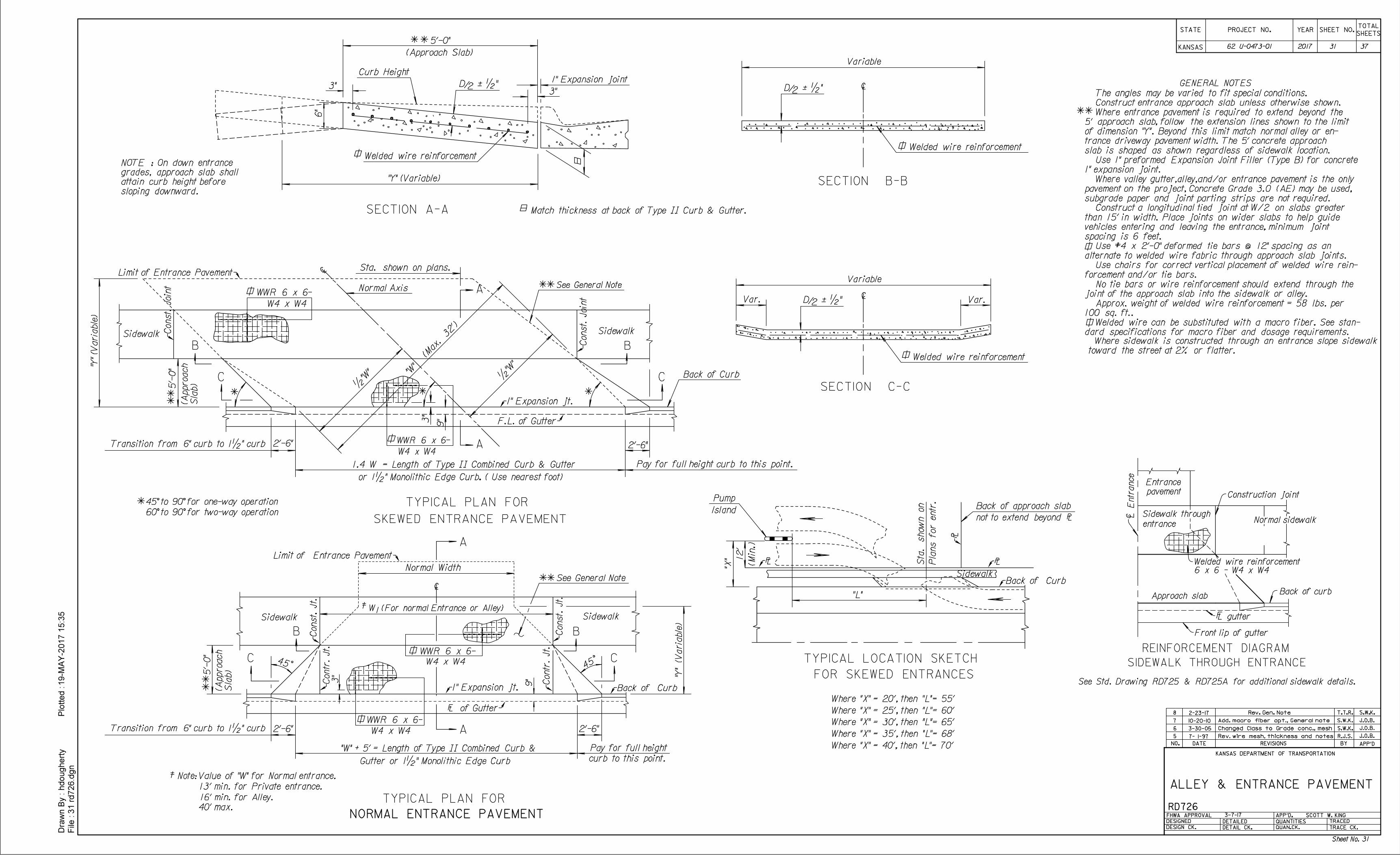
6"
"X" 12'
"L"
Pump
Island
Sta. s
how
n on
Pla
ns for entr.
Sidewalk
5'-0"
3"3"
Var.
Variable
"Y" (Variable)
(Approach Slab)
sloping downward.
attain curb height before
grades, approach slab shall
NOTE : On down entrance
Var.
Back of approach slab
The angles may be varied to fit special conditions.
1" Expansion jointGENERAL NOTES
45° to 90° for one-way operation
60° to 90° for two-way operation
Variable
/2
Match thickness at back of Type || Curb & Gutter.
D á •"
/2D á •"
/2D á •"
SECTION B-B
SECTION C-C
SECTION A-A
2'-6"
45°
3"
9"
"Y" (
Varia
ble)
5'-
0"
Normal Width
{
B
Pay for full height
curb to this point.
1
2'-6"
î of GutterÛ
TYPICAL PLAN FOR
NORMAL ENTRANCE PAVEMENT
Gutter or 1•" Monolithic Edge Curb
A
A
ÚConst. Jt.
ÙConst. Jt.
ÙContr. Jt.
ÚContr. Jt.
Ú1" Expansion jt.
CC 54°
B
Note: Value of "W" for Normal entrance.
13' min. for Private entrance.
16' min. for Alley.
40' max.
W (For normal Entrance or Alley)
"W" + 5' = Length of Type || Combined Curb &
{
2'-6"
(Max. 32')
•"W"
Sla
b)
(Approach
5'-
0"
"Y" (V
aria
ble)
"W"
3"
9"
2'-6"
1.4 W = Length of Type || Combined Curb & Gutter
or 1•" Monolithic Edge Curb. ( Use nearest foot)
B
C
A
B
F.L. of GutterÛ
TYPICAL PLAN FOR
SKEWED ENTRANCE PAVEMENT
ÙConst. J
oint
See General Note
C
Ú1" Expansion jt.
•"W"
ATransition from 6" curb to 1•" curb
Transition from 6" curb to 1•" curb
ì
{
(Min.)
not to extend beyond ð
TYPICAL LOCATION SKETCH
FOR SKEWED ENTRANCES
Where "X" = 20', then "L"= 55'
Where "X" = 25', then "L"= 60'
Where "X" = 30', then "L"= 65'
Where "X" = 35', then "L"= 68'
Where "X" = 40', then "L"= 70'
W4 x W4
Welded wire reinforcement
Welded wire reinforcement
Welded wire reinforcement
WWR 6 x 6-
31 rd726.d
gn
File :
Dra
wn B
y :
hdougherty
Plotted :19-M
AY-2
017 1
5:3
5
STATE
KANSAS
YEARPROJECT N0. SHEET NO.
DATE REVISIONS BY APP'DNO.
KANSAS DEPARTMENT OF TRANSPORTATION
RD726
DESIGNED
DETAILED
DESIGN CK. DETAIL CK.
QUANTITIES
QUAN.CK.
TRACED
TRACE CK.
APP'D.
SHEETS
TOTAL
ALLEY & ENTRANCE PAVEMENT
J.O.B.5 R.J.S.
J.O.B.
7- 1-97 Rev. wire mesh, thickness and notes
J.O.B.
6 S.W.K.Changed Class to Grade conc., mesh3-30-05
S.W.K.
7 S.W.K.10-20-10
Use #4 x 2'-0" deformed tie bars @ 12" spacing as an
alternate to welded wire fabric through approach slab joints.
Construct a longitudinal tied joint at W/2 on slabs greater
than 15' in width. Place joints on wider slabs to help guide
vehicles entering and leaving the entrance, minimum joint
spacing is 6 feet.
Construct entrance approach slab unless otherwise shown.
slab is shaped as shown regardless of sidewalk location.
Where entrance pavement is required to extend beyond the
5' approach slab, follow the extension lines shown to the limit
of dimension "Y". Beyond this limit match normal alley or en-
trance driveway pavement width. The 5' concrete approach
Add. macro fiber opt., General note
Where valley gutter,alley,and/or entrance pavement is the only
pavement on the project, Concrete Grade 3.0 (AE) may be used,
subgrade paper and joint parting strips are not required.
No tie bars or wire reinforcement should extend through the
joint of the approach slab into the sidewalk or alley.
Approx. weight of welded wire reinforcement = 58 lbs. per
100 sq. ft..
Curb Height
Sta. shown on plans.
Normal AxisWWR 6 x 6-
W4 x W4
Back of Curb
ÚConst. J
oint
Limit of Entrance PavementÜ
Limit of Entrance PavementÜ
WWR 6 x 6-
W4 x W4
WWR 6 x 6-
W4 x W4
Sla
b)
(Approach
ÚBack of Curb
See General Note
Úð
Úð
ÚBack of Curb
Úð
Use 1" preformed Expansion Joint Filler (Type B) for concrete
1" expansion joint.
SidewalkSidewalk
Sidewalk Sidewalk
Pay for full height curb to this point.
REINFORCEMENT DIAGRAM
L E
ntr
ance
c Sidewalk through
entrance
Approach slabBack of curb
L gutterF
Front lip of gutter
Entrance
pavement Construction joint
Normal sidewalk
Welded wire reinforcement
6 x 6 - W4 x W4
SIDEWALK THROUGH ENTRANCE
See Std. Drawing RD725 & RD725A for additional sidewalk details.
Use chairs for correct vertical placement of welded wire rein-
forcement and/or tie bars.
Welded wire can be substituted with a macro fiber. See stan-
dard specifications for macro fiber and dosage requirements.
FHWA APPROVAL
8 2-23-17 T.T.R.Rev. Gen. Note
SCOTT W. KING
toward the street at 2% or flatter.
Where sidewalk is constructed through an entrance slope sidewalk
3-7-17
62 U-0473-01 2017 31 37
Sheet No. 31
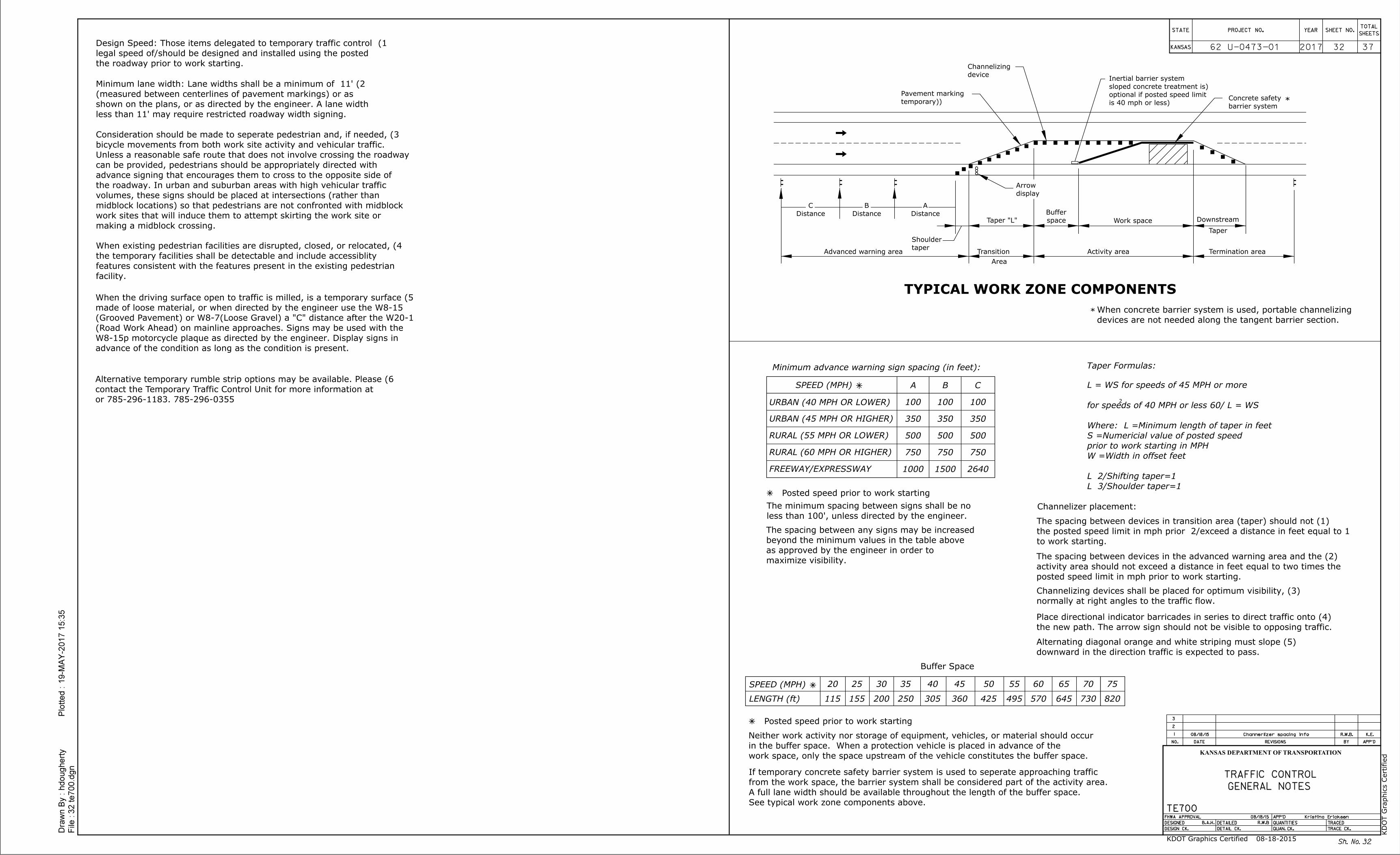
Sh. No.
2017 3732
32
Taper
Work space Downstream
TYPICAL WORK ZONE COMPONENTS
Advanced warning area Transition
Area
Activity area Termination area
SPEED (MPH)
LENGTH (ft)
20
115
25
155
30
200
35
250
40
305
45
360
50
425 495
55 60
570
65
645
70
730
75
820
Dra
wn B
y :
File :
hdougherty
Plotted :
32 te700.d
gn
19-M
AY-2
017 1
5:3
5
3
2
1 08/18/15
K.E.
R.W.B.
REVISIONS BY APP'DDATENO.
TRACED
TRACE CK.
APP'D
QUANTITIES
QUAN. CK.
DETAILED
DETAIL CK.
FHWA APPROVAL
DESIGNED
DESIGN CK.
KANSAS
STATE PROJECT NO. YEARTOTAL
SHEETSSHEET NO.
KANSAS DEPARTMENT OF TRANSPORTATION
TE700 08/18/15
B.A.H.
R.W.B
Kristina Ericksen
Channerlizer spacing info
GENERAL NOTES
TRAFFIC CONTROL
Posted speed prior to work starting
2
(temporary)
Pavement marking
device
Channelizing
is 40 mph or less)
optional if posted speed limit
(sloped concrete treatment is
Inertial barrier system
barrier system
Concrete safety
display
Arrow
taper
Shoulder
Taper "L" space
BufferDistance
A
Distance
B
Distance
C
Minimum advance warning sign spacing (in feet):
URBAN (40 MPH OR LOWER)
URBAN (45 MPH OR HIGHER)
RURAL (55 MPH OR LOWER)
RURAL (60 MPH OR HIGHER)
1000
750
500
350
100
A B
100
350
500
750
1500 2640
750
500
350
100
C
less than 100', unless directed by the engineer.
The minimum spacing between signs shall be no
maximize visibility.
as approved by the engineer in order to
beyond the minimum values in the table above
The spacing between any signs may be increased
W =Width in offset feet
prior to work starting in MPH
S =Numericial value of posted speed
Where: L =Minimum length of taper in feet
L = WS for speeds of 45 MPH or more
Taper Formulas:
Buffer Space
devices are not needed along the tangent barrier section.
When concrete barrier system is used, portable channelizing
*
*
SPEED (MPH)
Posted speed prior to work starting
the roadway prior to work starting.
1) Design Speed: Those items delegated to temporary traffic control
less than 11' may require restricted roadway width signing.
shown on the plans, or as directed by the engineer. A lane width
(measured between centerlines of pavement markings) or as
2) Minimum lane width: Lane widths shall be a minimum of 11'
facility.
features consistent with the features present in the existing pedestrian
the temporary facilities shall be detectable and include accessiblity
4) When existing pedestrian facilities are disrupted, closed, or relocated,
785-296-0355 or 785-296-1183.
contact the Temporary Traffic Control Unit for more information at
6) Alternative temporary rumble strip options may be available. Please
making a midblock crossing.
work sites that will induce them to attempt skirting the work site or
midblock locations) so that pedestrians are not confronted with midblock
volumes, these signs should be placed at intersections (rather than
the roadway. In urban and suburban areas with high vehicular traffic
advance signing that encourages them to cross to the opposite side of
can be provided, pedestrians should be appropriately directed with
Unless a reasonable safe route that does not involve crossing the roadway
bicycle movements from both work site activity and vehicular traffic.
3) Consideration should be made to seperate pedestrian and, if needed,
advance of the condition as long as the condition is present.
W8-15p motorcycle plaque as directed by the engineer. Display signs in
(Road Work Ahead) on mainline approaches. Signs may be used with the
(Grooved Pavement) or W8-7(Loose Gravel) a "C" distance after the W20-1
made of loose material, or when directed by the engineer use the W8-15
5) When the driving surface open to traffic is milled, is a temporary surface
Channelizer placement:
normally at right angles to the traffic flow.
(3) Channelizing devices shall be placed for optimum visibility,
to work starting.
(1) The spacing between devices in transition area (taper) should not
posted speed limit in mph prior to work starting.
activity area should not exceed a distance in feet equal to two times the
(2) The spacing between devices in the advanced warning area and the
work space, only the space upstream of the vehicle constitutes the buffer space.
in the buffer space. When a protection vehicle is placed in advance of the
Neither work activity nor storage of equipment, vehicles, or material should occur
See typical work zone components above.
A full lane width should be available throughout the length of the buffer space.
from the work space, the barrier system shall be considered part of the activity area.
If temporary concrete safety barrier system is used to seperate approaching traffic
the new path. The arrow sign should not be visible to opposing traffic.
(4) Place directional indicator barricades in series to direct traffic onto
downward in the direction traffic is expected to pass.
(5) Alternating diagonal orange and white striping must slope
KD
OT G
raphics C
ertified
KDOT Graphics Certified 08-18-2015
62 U-0473-01
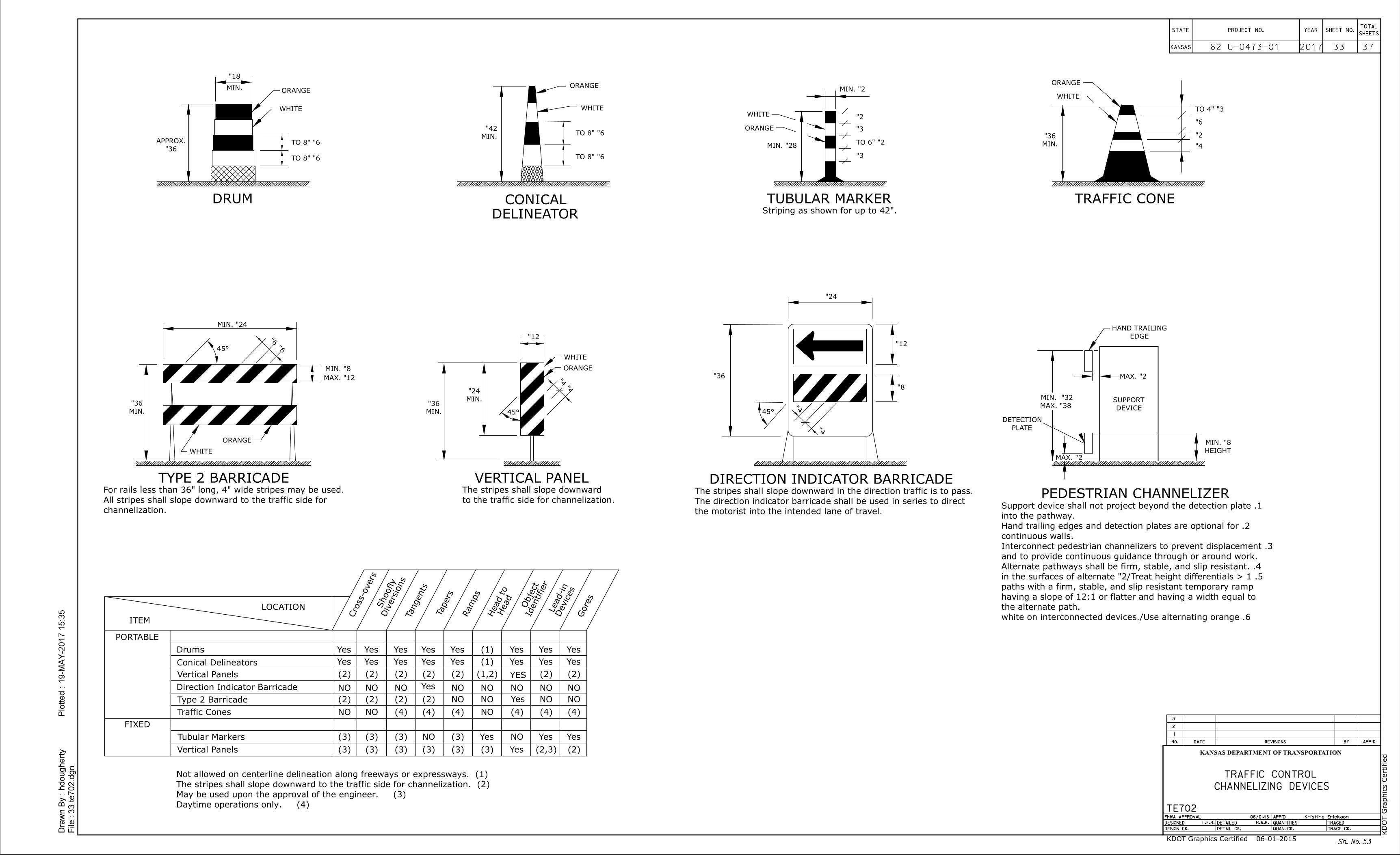
Sh. No.
2017 3733
33
Dra
wn B
y :
File :
hdougherty
Plotted :
33 te702.d
gn
19-M
AY-2
017 1
5:3
5
3
2
1
REVISIONS BY APP'DDATENO.
TRACED
TRACE CK.
APP'D
QUANTITIES
QUAN. CK.
DETAILED
DETAIL CK.
FHWA APPROVAL
DESIGNED
DESIGN CK.
KANSAS
STATE PROJECT NO. YEARTOTAL
SHEETSSHEET NO.
KANSAS DEPARTMENT OF TRANSPORTATION
TE702 06/01/15
L.E.R.
R.W.B.
Kristina Ericksen
CHANNELIZING DEVICES
TRAFFIC CONTROL
36"
APPROX.
18"
MIN. ORANGE
WHITE
6" TO 8"
6" TO 8"
DRUM
ORANGE
WHITE
TRAFFIC CONE
6"
2"
4"
3" TO 4"
MIN.
36"
ORANGE
WHITE
VERTICAL PANEL
4"4"
MIN.
24"
MIN.
36"
45°
to the traffic side for channelization.
The stripes shall slope downward
12"
DELINEATOR
CONICAL
6" TO 8"
6" TO 8"
MIN.
42"
2" MIN.
2"
3"
2" TO 6"
3"
ORANGE
WHITE
TUBULAR MARKER
28" MIN.
Striping as shown for up to 42".
MIN.
36"
24" MIN.
8" MIN.
12" MAX.
6"
6"
ORANGE
WHITE
45°
TYPE 2 BARRICADE
channelization.
All stripes shall slope downward to the traffic side for
For rails less than 36" long, 4" wide stripes may be used.
36"
24"
12"
8"
4"
4"45°
DIRECTION INDICATOR BARRICADE
the motorist into the intended lane of travel.
The direction indicator barricade shall be used in series to direct
The stripes shall slope downward in the direction traffic is to pass.
DEVICE
SUPPORT
EDGE
HAND TRAILING
2" MAX.
2" MAX.
PLATE
DETECTION
HEIGHT
8" MIN.
38" MAX.
32" MIN.
PEDESTRIAN CHANNELIZER
LOCATION
ITEM
PORTABLE
FIXED
NO
(1,2)
(1)
(2)
NO
YES
(3) NO
(1)
(2)
(3) (3) (3) (3) (3) (3)
(3)(3)(3)
Gores
Devices
Lead-in
(2)(2,3)
Direction Indicator Barricade
Vertical Panels
Conical Delineators
Drums
Type 2 Barricade
Tubular Markers
Vertical Panels
Yes
Yes Yes
Yes
Yes
Yes
Yes
Yes
Yes
Yes
Yes
Yes
Yes
Yes
Yes
Yes
Yes
Yes
Yes
YesYesYes
Cross-o
vers
Diversio
ns
Shoofly
Tangents
Tapers
Ra
mps
Head
Head to
Identifier
Obje
ct
Traffic Cones
(2) (2) (2) (2) (2) (2)
NO NO NO
NO NO
NO NO NO NO
NONO(2) (2) (2)
NO NO (4) (4) (4) (4) (4) (4)
(4) Daytime operations only.
(3) May be used upon the approval of the engineer.
(2) The stripes shall slope downward to the traffic side for channelization.
(1) Not allowed on centerline delineation along freeways or expressways.
NO
the alternate path.
having a slope of 12:1 or flatter and having a width equal to
paths with a firm, stable, and slip resistant temporary ramp
4. Alternate pathways shall be firm, stable, and slip resistant.
and to provide continuous guidance through or around work.
3. Interconnect pedestrian channelizers to prevent displacement
continuous walls.
2. Hand trailing edges and detection plates are optional for
into the pathway.
1. Support device shall not project beyond the detection plate
KD
OT G
raphics C
ertified
KDOT Graphics Certified 06-01-2015
62 U-0473-01
ORANGE
WHITE
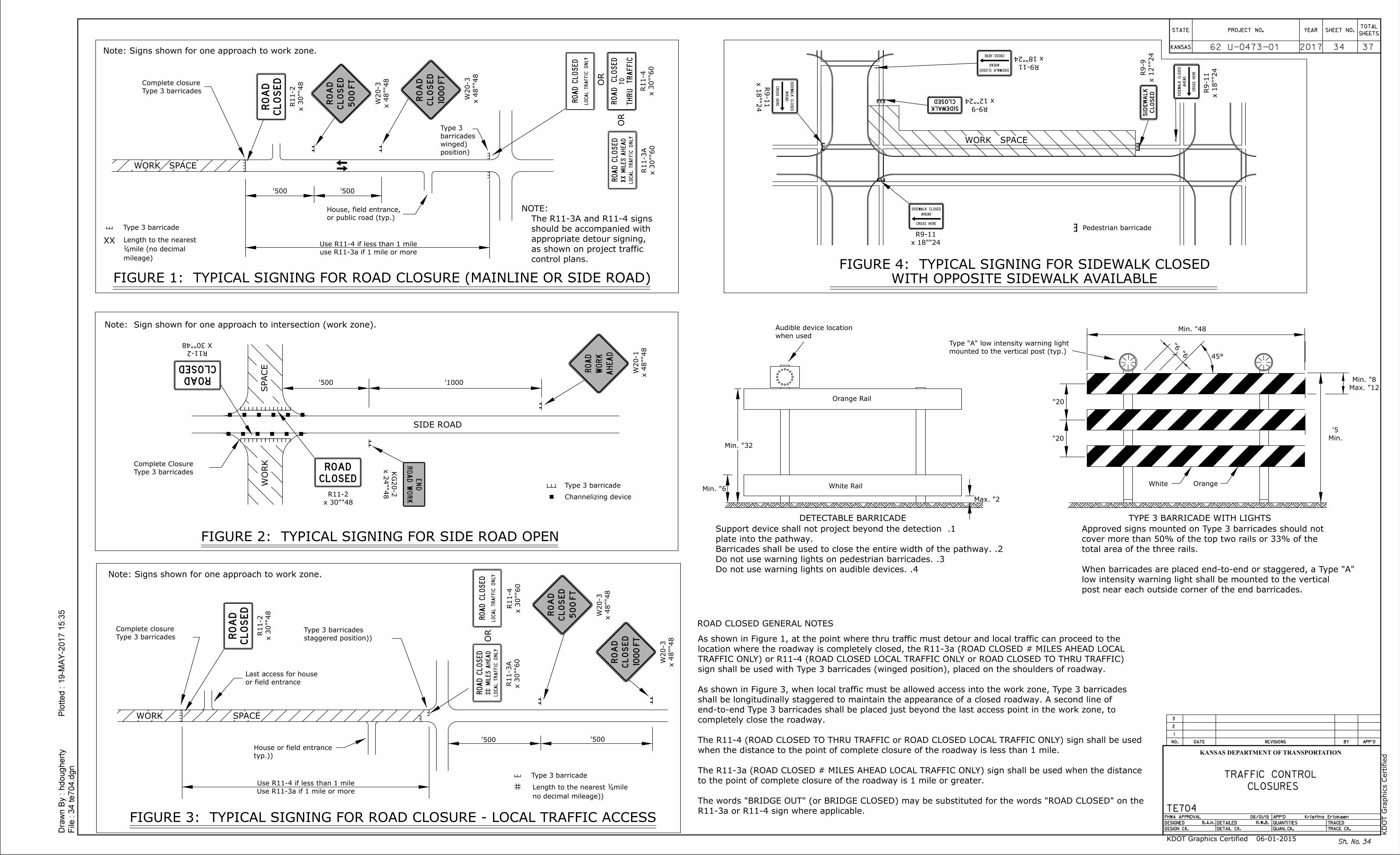
1000'
500' 500'
500'
500'500'
OR
48"
x 48"
W20-3
48"
x 48"
W20-3
48"
x 30"
R11-2
OR
NOTE:
60"
x 30"
R11-4
60"
x 30"
R11-3
A
WO
RK
SIDE ROAD
FIGURE 2: TYPICAL SIGNING FOR SIDE ROAD OPEN
48"X 30"
R11-248"x 30"
R11-2
Note: Sign shown for one approach to intersection (work zone).
OR
WORK
48"
x 30"
R11-2
60"
x 30"
R11-4
60"
x 30"
R11-3
A
48"
x 48"
W20-1
48"
x 24"
KG
20-2
48"
x 48"
W20-3
48"
x 48"
W20-3
Sh. No.
2017 3734
34
Dra
wn B
y :
File :
hdougherty
Plotted :
34 te704.d
gn
19-M
AY-2
017 1
5:3
5
3
2
1
REVISIONS BY APP'DDATENO.
TRACED
TRACE CK.
APP'D
QUANTITIES
QUAN. CK.
DETAILED
DETAIL CK.
FHWA APPROVAL
DESIGNED
DESIGN CK.
KANSAS
STATE PROJECT NO. YEARTOTAL
SHEETSSHEET NO.
KANSAS DEPARTMENT OF TRANSPORTATION
TE704 06/01/15
B.A.H.
R.W.B.
Kristina Ericksen
CLOSURES
TRAFFIC CONTROL
Type 3 barricade
Type 3 barricades
Complete closure
position)
(winged
barricades
Type 3
control plans.
as shown on project traffic
appropriate detour signing,
should be accompanied with
The R11-3A and R11-4 signs
Note: Signs shown for one approach to work zone.
Note: Signs shown for one approach to work zone.
Type 3 barricades
Complete Closure
Type 3 barricade
Type 3 barricade
Type 3 barricades
Complete closure
(staggered position)
Type 3 barricades
(no decimal mileage)
mile41Length to the nearest
Use R11-3a if 1 mile or more
Use R11-4 if less than 1 mile
(typ.)
House or field entrance
or field entrance
Last access for house
FIGURE 1: TYPICAL SIGNING FOR ROAD CLOSURE (MAINLINE OR SIDE ROAD)
use R11-3a if 1 mile or more
Use R11-4 if less than 1 mile
mileage)
mile (no decimal41
Length to the nearest
or public road (typ.)
House, field entrance,
Channelizing device
FIGURE 3: TYPICAL SIGNING FOR ROAD CLOSURE - LOCAL TRAFFIC ACCESS
post near each outside corner of the end barricades.
low intensity warning light shall be mounted to the vertical
When barricades are placed end-to-end or staggered, a Type "A"
total area of the three rails.
cover more than 50% of the top two rails or 33% of the
Approved signs mounted on Type 3 barricades should not
20"
20"
6"6"
45°
TYPE 3 BARRICADE WITH LIGHTS
48" Min.
12" Max.
8" Min.
Min.
5'
OrangeWhite
mounted to the vertical post (typ.)
Type "A" low intensity warning light
DETECTABLE BARRICADE
32" Min.
2" Max.
6" Min.
when used
Audible device location
ROAD CLOSED GENERAL NOTES
Pedestrian barricade
R11-3a or R11-4 sign where applicable.
The words "BRIDGE OUT" (or BRIDGE CLOSED) may be substituted for the words "ROAD CLOSED" on the
to the point of complete closure of the roadway is 1 mile or greater.
The R11-3a (ROAD CLOSED # MILES AHEAD LOCAL TRAFFIC ONLY) sign shall be used when the distance
when the distance to the point of complete closure of the roadway is less than 1 mile.
The R11-4 (ROAD CLOSED TO THRU TRAFFIC or ROAD CLOSED LOCAL TRAFFIC ONLY) sign shall be used
completely close the roadway.
end-to-end Type 3 barricades shall be placed just beyond the last access point in the work zone, to
shall be longitudinally staggered to maintain the appearance of a closed roadway. A second line of
As shown in Figure 3, when local traffic must be allowed access into the work zone, Type 3 barricades
sign shall be used with Type 3 barricades (winged position), placed on the shoulders of roadway.
TRAFFIC ONLY) or R11-4 (ROAD CLOSED LOCAL TRAFFIC ONLY or ROAD CLOSED TO THRU TRAFFIC)
location where the roadway is completely closed, the R11-3a (ROAD CLOSED # MILES AHEAD LOCAL
As shown in Figure 1, at the point where thru traffic must detour and local traffic can proceed to the
WITH OPPOSITE SIDEWALK AVAILABLE
FIGURE 4: TYPICAL SIGNING FOR SIDEWALK CLOSED
WORK SPACE
24"
x 12"
R9-9
24"
x 18"
R9-11
24"x 18"
R9-11
24"
x 18"
R9-11
24"x 18"
R9-11
24"x 12"
R9-9
Orange Rail
White Rail
WORK SPACE
SP
AC
E
4. Do not use warning lights on audible devices.
3. Do not use warning lights on pedestrian barricades.
2. Barricades shall be used to close the entire width of the pathway.
plate into the pathway.
1. Support device shall not project beyond the detection
SPACE
XX
KD
OT G
raphics C
ertified
KDOT Graphics Certified 06-01-2015
62 U-0473-01
RO
AD
CLOSED
LOCAL
TR
AFFIC
ONLY
RO
AD
CLOSED
LOCAL
TR
AFFIC
ONLY
MIL
ES
AHEA
D
RO
AD
CLOSED
LOCAL
TR
AFFIC
ONLY
RO
AD
CL
OS
ED
ROAD
CLOSED
ROAD
CLOSED
RO
AD
CL
OS
ED
TH
RU
TR
AFFIC
RO
AD
CLOSED
TO
RO
AD
AHEA
D
WO
RK
RO
AD
CL
OS
ED
500
FT
RO
AD
CL
OS
ED
1000
FT
RO
AD
CL
OS
ED
500
FT
RO
AD
CL
OS
ED
1000
FT
E
ND
RO
AD
WO
RK
SID
EW
ALK
CLOSED
CROSS
HERE
AHEA
D
SIDEWALK CLOSED
CROSS HERE
AHEAD
SIDEWALK CLOSED
CROSS HERE
AHEAD
SID
EW
ALK
CLOSED
CROSS
HERE
AHEA
D
SID
EW
AL
K
CL
OS
ED
SIDEWALK
CLOSED
RO
AD
CLOSED
LOCAL
TR
AFFIC
ONLY
MIL
ES
AHEA
DX
X
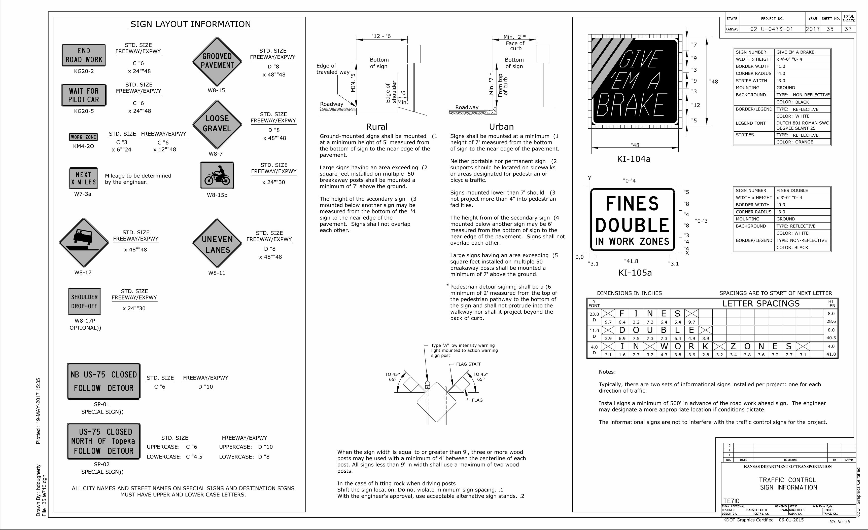
Sh. No.
2017 3735
35
3" C
48"x 12"
6" C
48"x 24"
6" C
SIGN LAYOUT INFORMATION
STD. SIZE
24"x 6"
W8-11
W7-3a
STD. SIZE
48"x 24"
6" C
STD. SIZE
STD. SIZE
10" D6" C
KG20-2
KM4-2O
KG20-5
SP-01
STD. SIZE
8" D
48"x 48"
W8-17
STD. SIZE
48"x 48"
(SPECIAL SIGN)
W8-17P
STD. SIZE
30"x 24"
(OPTIONAL)
STD. SIZE
10" D6" C
SP-02
(SPECIAL SIGN)
UPPERCASE: UPPERCASE:
LOWERCASE: LOWERCASE:4.5" C 8" D
Bottom
Min.
6' - 12'
5'
MIN.
should
er
Edge of
6'
Roadway
traveled way
Edge of of sign
Rural Urban
each other.
pavement. Signs shall not overlap
sign to the near edge of the
4' measured from the bottom of the
mounted below another sign may be
3) The height of the secondary sign
minimum of 7' above the ground.
breakaway posts shall be mounted a
50 square feet installed on multiple
2) Large signs having an area exceeding
pavement.
the bottom of sign to the near edge of the
at a minimum height of 5' measured from
1) Ground-mounted signs shall be mounted
FLAG
FLAG STAFF
sign post
light mounted to action warning
Type "A" low intensity warning
65°
45° TO
65°
45° TO
9"
3"
9"
3"
12"
5"
48"
48"
7"
5"
8"
4"
3'-0"8"
3"
4"
4"X
3.1"41.8"
3.1"
0,0
Y
0.9"
MOUNTING
BACKGROUND
WIDTH x HEIGHT
SIGN NUMBER
CORNER RADIUS
BORDER WIDTH
GROUND
3.0"
4'-0" x 3'-0"
FINES DOUBLE
KI-104a
23.0
D
8.0
28.69.7 6.4 3.2 7.3 6.4 5.4 9.7
11.0
D
8.0
40.33.9 6.9 7.5 7.3 7.3 6.4 4.9 3.9
4.0
D
4.0
41.83.1 1.6 2.7 3.2 4.3 3.8 3.6 2.8 3.2 3.4 3.8 3.6 3.2 2.7 3.1
Y
FONT
HT
LENLETTER SPACINGS
KI-105a
SPACINGS ARE TO START OF NEXT LETTERDIMENSIONS IN INCHES
4'-0"
F I N E S
D O U B L E
I N W O R K Z O N E S
1.0"
TYPE:
TYPE:
COLOR:
COLOR:
MOUNTING
BACKGROUND
WIDTH x HEIGHT
SIGN NUMBER
CORNER RADIUS
BORDER WIDTH
REFLECTIVE
GROUND
4.0"
4'-0" x 4'-0"
WHITE
BLACK
NON-REFLECTIVE
GIVE EM A BRAKE
STRIPE WIDTH 3.0"
COLOR:
TYPE:STRIPES REFLECTIVE
ORANGE
LEGEND FONT
25 DEGREE SLANT
DUTCH 801 ROMAN SWC
The informational signs are not to interfere with the traffic control signs for the project.
may designate a more appropriate location if conditions dictate.
Install signs a minimum of 500' in advance of the road work ahead sign. The engineer
direction of traffic.
Typically, there are two sets of informational signs installed per project: one for each
Notes:
2. With the engineer's approval, use acceptable alternative sign stands.
1. Shift the sign location. Do not violate minimum sign spacing.
In the case of hitting rock when driving posts
posts.
post. All signs less than 9' in width shall use a maximum of two wood
posts may be used with a minimum of 4' between the centerline of each
When the sign width is equal to or greater than 9', three or more wood
Bottom
Face of
Fro
m t
op
Roadway
* 7'
Min.
of curb
of sign
curb
* 2' Min.
back of curb.
walkway nor shall it project beyond the
the sign and shall not protrude into the
the pedestrian pathway to the bottom of
minimum of 2' measured from the top of
6) Pedestrian detour signing shall be a
minimum of 7' above the ground.
breakaway posts shall be mounted a
50 square feet installed on multiple
5) Large signs having an area exceeding
overlap each other.
near edge of the pavement. Signs shall not
measured from the bottom of sign to the
mounted below another sign may be 6'
4) The height from of the secondary sign
facilities.
not project more than 4" into pedestrian
3) Signs mounted lower than 7' should
bicycle traffic.
or areas designated for pedestrian or
supports should be located on sidewalks
2) Neither portable nor permanent sign
of sign to the near edge of the pavement.
height of 7' measured from the bottom
1) Signs shall be mounted at a minimum
*
TYPE: REFLECTIVE
COLOR: WHITE
TYPE: NON-REFLECTIVE
COLOR: BLACK
by the engineer.
Mileage to be determined
STD. SIZE
8" D
48"x 48"
STD. SIZE
8" D
48"x 48"
STD. SIZE
30"x 24"
W8-15
W8-15p
W8-7
Dra
wn B
y :
File :
hdougherty
Plotted :
35 te710.d
gn
19-M
AY-2
017 1
5:3
5
3
2
1
REVISIONS BY APP'DDATENO.
TRACED
TRACE CK.
APP'D
QUANTITIES
QUAN. CK.
DETAILED
DETAIL CK.
FHWA APPROVAL
DESIGNED
DESIGN CK.
KANSAS
STATE PROJECT NO. YEARTOTAL
SHEETSSHEET NO.
KANSAS DEPARTMENT OF TRANSPORTATION
TE710 06/01/15
R.W.B.
R.W.B.
Kristina Pyle
SIGN INFORMATION
TRAFFIC CONTROL
KD
OT G
raphics C
ertified
KDOT Graphics Certified 06-01-2015
62 U-0473-01
UNEVE
LANES
N
END
ROAD WORK
NEXT
X MILES
WORK ZONE
PILOTCAR
IAW T ROF
US-75 CLOSED
FOLLOW DETOUR
NB
MUST HAVE UPPER AND LOWER CASE LETTERS.
ALL CITY NAMES AND STREET NAMES ON SPECIAL SIGNS AND DESTINATION SIGNS
SHOULDER
DROP-OFF
US-75 CLOSED
FOLLOW DETOUR
'EM A
BRAKE
GIVE
FINES
DOUBLEIN WORK ZONES
GROOVED
PAVEMENT
GRAVEL
LOOSE
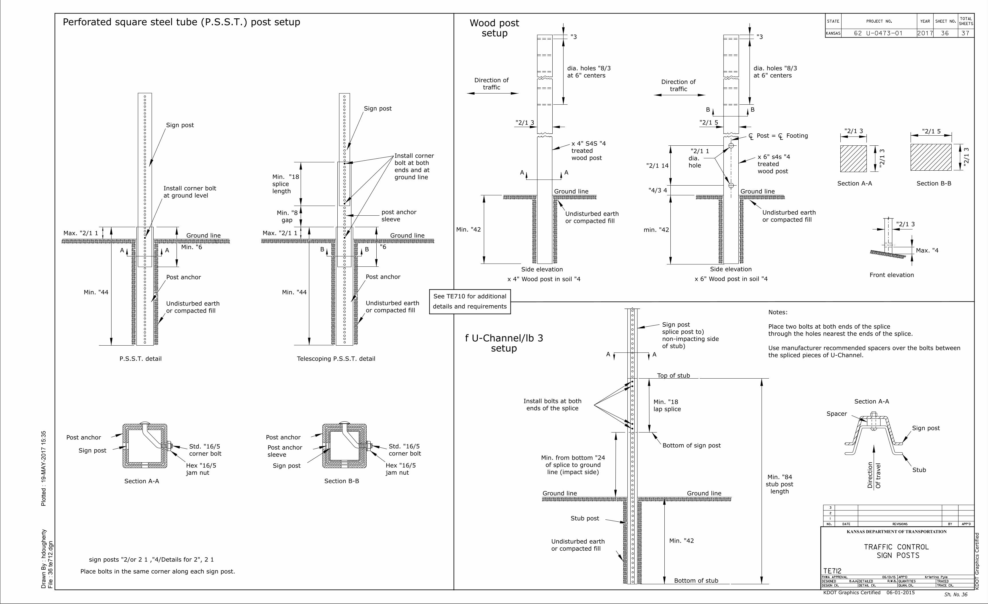
Sign post
Ground line
AA
Sign post
6"B B
Ground line
Sign post
3"
42" min.
3"
BB
AA
AA
Bottom of sign post
Ground line Ground line
Stub post
Bottom of stub
Direction
Of travel
Stub
Sign post
Spacer
Top of stub
Side elevationFront elevation
Side elevation
4" x 4" Wood post in soil 4" x 6" Wood post in soil
Sh. No.
2017 3736
36
44" Min.44" Min.
Section B-B
Sign post
sleeve
Post anchor
length
stub post
84" Min.
at ground level
Install corner boltGround line Ground line
ground line
ends and at
bolt at both
Install corner
Place bolts in the same corner along each sign post.
the spliced pieces of U-Channel.
Use manufacturer recommended spacers over the bolts between
through the holes nearest the ends of the splice.
Place two bolts at both ends of the splice
Notes:
of stub)
non-impacting side
(splice post to
Sign post
sleeve
post anchor
gap
8" Min.
Post anchor
or compacted fill
Undisturbed earth
or compacted fill
Undisturbed earth
Post anchor
Post anchor Post anchor
corner bolt
jam nut
Section A-A
corner bolt
jam nut
Telescoping P.S.S.T. detailP.S.S.T. detail
6" Min.
length
splice
18" Min.
or compacted fill
Undisturbed earth
traffic
Direction ofat 6" centers
traffic
Direction of
hole
dia.
or compacted fill
Undisturbed earth
wood post
treated
4" x 6" s4s
at 6" centers
42" Min.
wood post
treated
4" x 4" S4SLC Post = C FootingL
4" Max.
Section A-A Section B-B
or compacted fill
Undisturbed earth
setup
Wood post
setup
ends of the splice
Install bolts at both
lap splice
18" Min.
line (impact side)
of splice to ground
24" Min. from bottom
42" Min.
Section A-A
Perforated square steel tube (P.S.S.T.) post setup
See TE710 for additional
details and requirements
Dra
wn B
y :
File :
hdougherty
Plotted :
36 te712.d
gn
19-M
AY-2
017 1
5:3
5
3
2
1
REVISIONS BY APP'DDATENO.
TRACED
TRACE CK.
APP'D
QUANTITIES
QUAN. CK.
DETAILED
DETAIL CK.
FHWA APPROVAL
DESIGNED
DESIGN CK.
KANSAS
STATE PROJECT NO. YEARTOTAL
SHEETSSHEET NO.
KANSAS DEPARTMENT OF TRANSPORTATION
TE712 06/01/15
B.A.H.
R.W.B.
Kristina Pyle
SIGN POSTS
TRAFFIC CONTROL
KD
OT G
raphics C
ertified
KDOT Graphics Certified 06-01-2015
62 U-0473-01
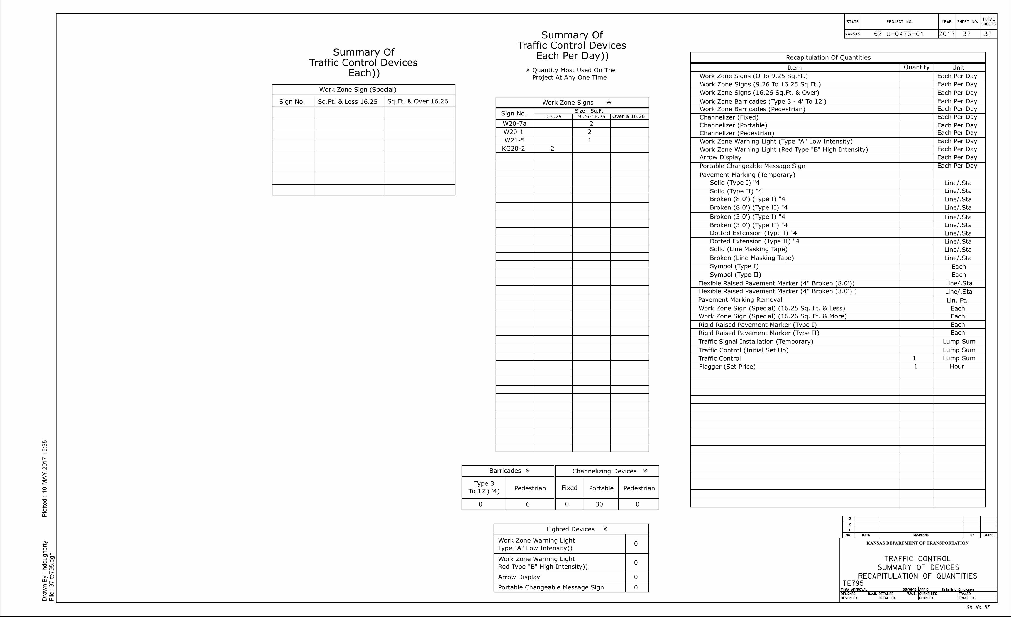
Recapitulation Of Quantities
Work Zone Sign (Special)
Work Zone Signs
Lighted Devices
0-9.25
Sign No. 16.25 Sq.Ft. & Less 16.26 Sq.Ft. & Over
Sign No.9.26-16.25 16.26 & Over
Size - Sq.Ft.
Item Quantity Unit
Work Zone Signs (O To 9.25 Sq.Ft.)
Work Zone Signs (9.26 To 16.25 Sq.Ft.)
Work Zone Signs (16.26 Sq.Ft. & Over)
Channelizer (Fixed)
Channelizer (Portable)
Work Zone Warning Light (Type "A" Low Intensity)
Work Zone Warning Light (Red Type "B" High Intensity)
Arrow Display
Portable Changeable Message Sign
Pavement Marking (Temporary)
Solid (Line Masking Tape)
Broken (Line Masking Tape)
Pavement Marking Removal
Work Zone Sign (Special) (16.25 Sq. Ft. & Less)
Work Zone Sign (Special) (16.26 Sq. Ft. & More)
Traffic Signal Installation (Temporary)
Traffic Control (Initial Set Up)
Traffic Control
Flagger (Set Price) 1 Hour
Lump Sum
Lump Sum
Lump Sum
Each
Each
Each
Each
Lin. Ft.
Each Per Day
Each Per Day
Each Per Day
Each Per Day
Each Per Day
Each Per Day
Each Per Day
Each Per Day
Each Per Day
Each Per Day
Arrow Display
Portable Changeable Message Sign
Channelizing Devices
Fixed Portable
Barricades
2017 3737
37
Flexible Raised Pavement Marker (4" Broken (8.0'))
Work Zone Barricades (Type 3 - 4' To 12')
Symbol (Type I)
Symbol (Type II)
Project At Any One Time
Quantity Most Used On The
(Type "A" Low Intensity)
Work Zone Warning Light
(Red Type "B" High Intensity)
Work Zone Warning Light
(4' To 12')
Type 3
Each
Each
(Each Per Day)
Traffic Control Devices
Summary Of
(Each)
Traffic Control Devices
Summary Of
4" Broken (8.0') (Type I)
4" Broken (8.0') (Type II)
4" Broken (3.0') (Type I)
4" Broken (3.0') (Type II)
4" Dotted Extension (Type I)
4" Dotted Extension (Type II)
4" Solid (Type II)
4" Solid (Type I)
Each Per DayWork Zone Barricades (Pedestrian)
Channelizer (Pedestrian) Each Per Day
Flexible Raised Pavement Marker (4" Broken (3.0') )
PedestrianPedestrian
Dra
wn B
y :
File :
hdougherty
Plotted :
37 te795.d
gn
19-M
AY-2
017 1
5:3
5
3
2
1
REVISIONS BY APP'DDATENO.
TRACED
TRACE CK.
APP'D
QUANTITIES
QUAN. CK.
DETAILED
DETAIL CK.
FHWA APPROVAL
DESIGNED
DESIGN CK.
KANSAS
STATE PROJECT NO. YEARTOTAL
SHEETSSHEET NO.
KANSAS DEPARTMENT OF TRANSPORTATION
TE795 06/01/15
B.A.H.
R.W.B.
Kristina Ericksen
RECAPITULATION OF QUANTITIES
SUMMARY OF DEVICES
TRAFFIC CONTROL
Rigid Raised Pavement Marker (Type I)
Rigid Raised Pavement Marker (Type II)
Sh. No.
1
60 0 0
0
0
0
0
W20-1 2
W21-5 1
KG20-2 2
W20-7a 2
30
62 U-0473-01