mks type 270d high accuracy signal conditioner. · 115817-p1 rev e, 7/98 instruction manual mks...
TRANSCRIPT

115817-P1Rev E, 7/98
Instruction Manual
MKS Type 270DHigh Accuracy
Signal Conditioner
Six Shattuck RoadAndover, MA 01810-2449(800) 227-8766 or (978) 975-2350
Fax: (978) 975-0093E-mail: [email protected]
Web site: http://www.mksinst.com

WARRANTYType 270D Equipment
MKS Instruments, Inc. (MKS) warrants that the equipment described above (the
“equipment”) manufactured by MKS shall be free from defects in materials and
workmanship for a period of one year from date of shipment and will for a period of two
years from the date of shipment, correctly perform all date-related operations, including
without limitation accepting data entry, sequencing, sorting, comparing, and reporting,
regardless of the date the operation is performed or the date involved in the operation,
provided that, if the equipment exchanges data or is otherwise used with equipment,
software, or other products of others, such products of others themselves correctly
perform all date-related operations and store and transmit dates and date-related data
in a format compatible with MKS equipment. THIS WARRANTY IS MKS’ SOLE
WARRANTY CONCERNING DATE-RELATED OPERATIONS.
For the period commencing with the date of shipment of this equipment and ending one
year later in the case of defects in materials and workmanship, but two years later in the
case of failure to comply with the date-related operations warranty, MKS will, at its
option, either repair or replace any part which is defective in materials or workmanship
or with respect to the date-related operations warranty without charge to the purchaser.
The foregoing shall constitute the exclusive and sole remedy of the purchaser for any
breach by MKS of this warranty.
The purchaser, before returning any equipment covered by this warranty, which is
asserted to be defective by the purchaser, shall make specific written arrangements
with respect to the responsibility for shipping the equipment and handling any other
incidental charges with the MKS sales representative or distributor from which the
equipment was purchased or, in the case of a direct purchase from MKS, with the MKS
home office in Andover, Massachusetts, USA.
This warranty does not apply to any equipment which has not been installed and used
in accordance with the specifications recommended by MKS for the proper and normal
use of the equipment. MKS shall not be liable under any circumstances for indirect,
special, consequential, or incidental damages in connection with, or arising out of, the
sale, performance, or use of the equipment covered by this warranty.
MKS recommends that all MKS pressure and flow products be calibrated periodically
(typically every 6 to 12 months) to ensure accurate readings. When a product is
returned to MKS for this periodic re-calibration it is considered normal preventative
maintenance not covered by any warranty.
THIS WARRANTY IS IN LIEU OF ALL OTHER RELEVANT WARRANTIES,
EXPRESSED OR IMPLIED, INCLUDING THE IMPLIED WARRANTY OF
MERCHANTABILITY AND THE IMPLIED WARRANTY OF FITNESS FOR A
PARTICULAR PURPOSE, AND ANY WARRANTY AGAINST INFRINGEMENT OF
ANY PATENT.
11-98 115817-P1

115817-P1Rev E, 7/98
MKS Type 270DHigh Accuracy
Signal Conditioner

Copyright © 1998 by MKS Instruments, Inc.
All rights reserved. No part of this work may be reproduced or transmitted in any form or byany means, electronic or mechanical, including photocopying and recording, or by anyinformation storage or retrieval system, except as may be expressly permitted in writing by MKSInstruments, Inc.
Printed in the United States of America
Baratron® is a registered trademark of MKS Instruments, Inc., Andover, MA
Table of Contents
iii
Table of Contents
Safety Information.................................................................................................................. 1
Symbols Used in This Instruction Manual.................................................................. 1
Symbols Found on the Unit ....................................................................................... 2
Safety Procedures and Precautions ............................................................................. 3
Sicherheitshinweise................................................................................................................ 5
In dieser Betriebsanleitung vorkommende Symbole ................................................... 5
Am Gerät angebrachte Symbole................................................................................. 6
Sicherheitsvorschriften und Vorsichtsmaßnahmen...................................................... 7
Informations relatives à la sécurité.......................................................................................... 9
Symboles utilisés dans ce manuel d'utilisation ........................................................... 9
Symboles apparaissant sur l'appareil .......................................................................... 10
Mesures de sécurité et mises en garde ........................................................................ 11
Información sobre seguridad................................................................................................... 13
Símbolos usados en el manual de instrucciones.......................................................... 13
Símbolos que aparecen en la unidad........................................................................... 14
Procedimientos y precauciones de seguridad .............................................................. 15
Chapter One: General Information......................................................................................... 17
Introduction ............................................................................................................... 17
How This Manual is Organized.................................................................................. 18
Manual Conventions ..................................................................................... 18
Terminology.................................................................................................. 18
Customer Support ...................................................................................................... 19
Chapter Two: Installation ...................................................................................................... 21
How to Unpack the Type 270 Instrument ................................................................... 21
Parts Checklist .............................................................................................. 21
Companion Products.................................................................................................. 23
Product Location and Requirements........................................................................... 24
General Requirements ................................................................................... 24

Table of Contents
iv
Chapter Three: Overview ........................................................................................................25
Front Panel Controls ..................................................................................................25
Display ..........................................................................................................25
The x10-3 and x10-6 Lamps ..........................................................................25
SENSOR RANGE Selector Switch ................................................................26
Display Units Selector Switch........................................................................26
RANGE SELECT Switch ..............................................................................26
SENSOR ZERO Controls ..............................................................................26
RESPONSE Toggle Switch ...........................................................................27
HEATER Lamp .............................................................................................27
HEATER Toggle Switch ...............................................................................27
POWER Switch .............................................................................................27
Rear Panel Controls....................................................................................................28
REMOTE Connector .....................................................................................28
ACCESSORY Connector ..............................................................................29
HEAD Connector...........................................................................................30
Power Entry Module......................................................................................30
BCD Connector .............................................................................................31
BCD Interface Signals................................................................................................34
REMOTE DISPLAY HOLD Line...............................................................34
Data Ready Line ............................................................................................34
Enable Lines ..................................................................................................34
Overranging Output on the 5½ Digit Unit (270-5) ......................................................35
MULTIPLEX Connector ...............................................................................36
Chapter Four: Operation ........................................................................................................37
How to Configure the 270 Instrument.........................................................................37
How to Change the Line Voltage Selection ................................................................40
How to Select the Range Setting Remotely.................................................................41
Additional Procedures for the 0.1 Torr Sensors...........................................................42
How to Adjust the Zero on the 0.1 Torr Full Scale Sensor..............................42
Using a Low Range Pressure Sensor with the Remote Zero Option................43
Chapter Five: Maintenance and Troubleshooting....................................................................45

Table of Contents
v
General ...................................................................................................................... 45
How to Replace the Fuses .......................................................................................... 46
Troubleshooting......................................................................................................... 48
Test A: Localizing the Malfunction to the Cable or the Electronics Unit....... 50
Test B: Localizing Malfunctions to the Electronics Unit ............................... 52
How to Recalibrate the 270 Unit ................................................................................ 52
Appendix A: Product Specifications.......................................................................... 53
Index...................................................................................................................................... 55

Table of Contents
vi
List of Figures and Tables
vii
List of Figures and Tables
Figures
Figure 1: Front Panel of the 270-4 Unit ................................................................................. 25
Figure 2: Rear Panel of the 270-4 Unit .................................................................................. 28
Figure 3: Interconnection Cables ........................................................................................... 37
Figure 4: Sensor Cable Plus Two Resistors ........................................................................... 51
Tables
Table 1: Definition of Symbols Found on the Unit .....................................................................2
Tabelle 2: Definitionen der am Gerät angebrachten Symbole......................................................6
Tableau 3: Définition des symboles apparaissant sur l'appareil .................................................10
Tabla 4: Definición de los símbolos que aparecen en la unidad.................................................14
Table 5: RESPONSE Switch Settings.......................................................................................27
Table 6: REMOTE Connector (J402) Pinout ............................................................................28
Table 7: ACCESSORY Connector (J401) Pinout .....................................................................29
Table 8: HEAD Connector (J403) Pinout..................................................................................30
Table 9: BCD Connector Pinout for Type 270-4 (4½ digit display) ..........................................31
Table 10: BCD Connector Pinout for the Type 270-5 ...............................................................33
Table 11: MULTIPLEX Connector (J405) Pinout.....................................................................36
Table 12: Remote Range Logic Levels .....................................................................................41
Table 13: Fuses for the Type 270 Instrument ............................................................................46
Table 14: Sensor Cable Voltage Check.....................................................................................50
Table 15: Electronics Unit Voltage Check ................................................................................52

List of Figures and Tables
viii

Safety Information Symbols Used in This Instruction Manual
1
Safety Information
Symbols Used in This Instruction Manual
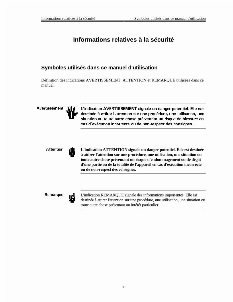
Definitions of WARNING, CAUTION, and NOTE messages used throughout the manual.
Warning The WARNING sign denotes a hazard. It calls attention to aprocedure, practice, condition, or the like, which, if notcorrectly performed or adhered to, could result in injury topersonnel.
Caution The CAUTION sign denotes a hazard. It calls attention to anoperating procedure, practice, or the like, which, if not correctlyperformed or adhered to, could result in damage to or destruction ofall or part of the product.
Note The NOTE sign denotes important information. It calls attention to aprocedure, practice, condition, or the like, which is essential to highlight.
Symbols Found on the Unit Safety Information
2
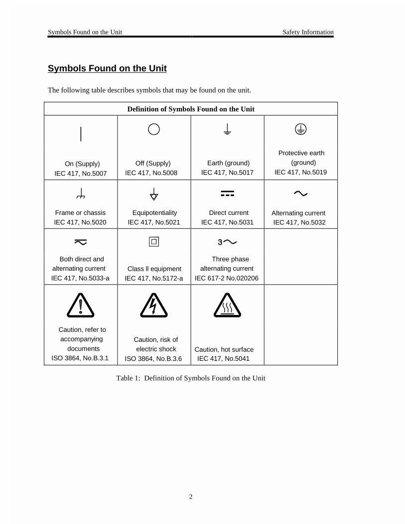
Symbols Found on the Unit
The following table describes symbols that may be found on the unit.
Definition of Symbols Found on the Unit
|
On (Supply) IEC 417, No.5007
Off (Supply)IEC 417, No.5008
Earth (ground) IEC 417, No.5017
Protective earth (ground)
IEC 417, No.5019
Frame or chassis IEC 417, No.5020
Equipotentiality IEC 417, No.5021
Direct current IEC 417, No.5031
Alternating currentIEC 417, No.5032
Both direct andalternating current
IEC 417, No.5033-aClass ll equipment
IEC 417, No.5172-a
Three phasealternating current
IEC 617-2 No.020206
Caution, refer toaccompanying
documentsISO 3864, No.B.3.1
Caution, risk ofelectric shock
ISO 3864, No.B.3.6Caution, hot surfaceIEC 417, No.5041
Table 1: Definition of Symbols Found on the Unit

Safety Information Safety Procedures and Precautions
3
Safety Procedures and Precautions
The following general safety precautions must be observed during all phases of operation of thisinstrument. Failure to comply with these precautions or with specific warnings elsewhere inthis manual violates safety standards of intended use of the instrument and may impair theprotection provided by the equipment. MKS Instruments, Inc. assumes no liability for thecustomer’s failure to comply with these requirements.
DO NOT SUBSTITUTE PARTS OR MODIFY INSTRUMENT
Do not install substitute parts or perform any unauthorized modification to the instrument.Return the instrument to an MKS Calibration and Service Center for service and repair to ensurethat all safety features are maintained.
SERVICE BY QUALIFIED PERSONNEL ONLY
Operating personnel must not remove instrument covers. Component replacement and internaladjustments must be made by qualified service personnel only.
GROUNDING THE PRODUCT
This product is grounded through the grounding conductor of the power cord. To avoid electricalshock, plug the power cord into a properly wired receptacle before connecting it to the productinput or output terminals. A protective ground connection by way of the grounding conductor inthe power cord is essential for safe operation.
DANGER ARISING FROM LOSS OF GROUND
Upon loss of the protective-ground connection, all accessible conductive parts (including knobsand controls that may appear to be insulating) can render an electrical shock.
GROUND AND USE PROPER ELECTRICAL FITTINGS
Dangerous voltages are contained within this instrument. All electrical fittings and cables mustbe of the type specified, and in good condition. All electrical fittings must be properly connectedand grounded.
USE THE PROPER POWER CORD
Use only a power cord that is in good condition and which meets the input power requirementsspecified in the manual.
Use only a detachable cord set with conductors that have a cross-sectional area equal to or greaterthan 0.75 mm2. The power cable should be approved by a qualified agency such as VDE,Semko, or SEV.
Safety Procedures and Precautions Safety Information
4
USE THE PROPER POWER SOURCE
This product is intended to operate from a power source that does not apply more voltagebetween the supply conductors, or between either of the supply conductors and ground, than thatspecified in the manual.
USE THE PROPER FUSE
Use only a fuse of the correct type, voltage rating, and current rating, as specified for yourproduct.
DO NOT OPERATE IN EXPLOSIVE ATMOSPHERES
To avoid explosion, do not operate this product in an explosive environment unless it has beenspecifically certified for such operation.
HIGH VOLTAGE DANGER
High voltage is present in the cable, and in the sensor when the controller is turned on.

Sicherheitshinweise In dieser Betriebsanleitung vorkommende Symbole
5
Sicherheitshinweise
In dieser Betriebsanleitung vorkommende Symbole
Definition der mit WARNUNG!, VORSICHT! und HINWEIS überschriebenen Abschnitte indieser Betriebsanleitung.
Warnung! &CU 5[ODQN 9#4070)� YGKUV CWH GKPG )GHCJTGPSWGNNG JKP� 'U
OCEJV CWH GKPGP #TDGKVUCDNCWH� GKPG #TDGKVUYGKUG� GKPGP
<WUVCPF QFGT GKPG UQPUVKIG )GIGDGPJGKV CWHOGTMUCO� FGTGP
WPUCEJIGO·G #WUHÒJTWPI D\Y� WPIGPÒIGPFG
$GTÒEMUKEJVKIWPI \W -ÌTRGTXGTNGV\WPI HÒJTGP MCPP�
8QTUKEJV� Das Symbol VORSICHT! weist auf eine Gefahrenquelle hin. Esmacht auf einen Bedienungsablauf, eine Arbeitsweise oder einesonstige Gegebenheit aufmerksam, deren unsachgemäße Ausführungbzw. Ungenügende Berücksichtigung zu einer Beschädigung oderZerstörung des Produkts oder von Teilen des Produkts führen kann.
*KPYGKU Das Symbol HINWEIS weist auf eine wichtige Mitteilung hin, die aufeinen Arbeitsablauf, eine Arbeitsweise, einen Zustand oder eine sonstigeGegebenheit von besonderer Wichtigkeit aufmerksam macht.

Am Gerät angebrachte Symbole Sicherheitshinweise
6
Am Gerät angebrachte Symbole
Der untenstehenden Tabelle sind die Bedeutungen der Symbole zu entnehmen, die an dem Gerätangebracht sind.
Definitionen der am Gerät angebrachten Symbole
|Ein (Netz)
IEC 417, Nr. 5007
Aus (Netz)
IEC 417, Nr. 5008
Erde
IEC 417, Nr. 5017
Schutzleiter
IEC 417, Nr. 5019
Rahmen oder Chassis
IEC 417, Nr. 5020
Äquipotentialanschluß
IEC 417, Nr. 5021
Gleichstrom
IEC 417, Nr. 5031
Wechselstrom
IEC 417, Nr. 5032
Wechselstrom und
Gleichstrom
IEC 417, Nr. 5033-a
Geräteklasse II
IEC 417, Nr. 5172-a
Drehstrom
IEC 617-2 Nr. 020206
Vorsicht! Bitte
Begleitdokumente
lesen!
ISO 3864, Nr. B.3.1
Vorsicht!
Stromschlaggefahr!
ISO 3864, Nr. B.3.6
Vorsicht!
Heiße Fläche!
IEC 417, Nr. 5041
Tabelle 2: Definitionen der am Gerät angebrachten Symbole

Sicherheitshinweise Sicherheitsvorschriften und Vorsichtsmaßnahmen
7
Sicherheitsvorschriften und Vorsichtsmaßnahmen
Die untenstehenden allgemeinen Sicherheitsvorschriften sind bei allen Betriebs-phasendieses Instruments zu befolgen. Jede Mißachtung dieser Sicherheits-vorschriften odersonstiger spezifischer Warnhinweise in dieser Betriebsanleitung stellt eineZuwiderhandlung der für dieses Instrument geltenden Sicherheits-standards dar und kanndie an diesem Instrument vorgesehenen Schutzvor-richtungen unwirksam machen. MKSInstruments, Inc. haftet nicht für eine Mißachtung dieser Sicherheitsvorschriften seitensdes Kunden.
Keine Teile austauschen und keine Veränderungen vornehmen!
Bauen Sie in das Instrument keine Ersatzteile ein, und nehmen Sie keine eigenmächtigenÄnderungen am Gerät vor! Schicken Sie das Instrument zu Wartungs- und Reparatur-zwecken aneinen MKS-Kalibrierungs- und -Kundendienst ein! Dadurch wird sicher-gestellt, daß alleSicherheitseinrichtungen voll funktionsfähig bleiben.
Wartung nur durch qualifizierte Fachleute!
Das Gehäuse des Instruments darf vom Bedienpersonal nicht geöffnet werden. Das Auswechselnvon Bauteilen und das Vornehmen von internen Einstellungen ist nur von qualifiziertenFachleuten durchzuführen.
Produkt erden!
Dieses Produkt ist mit einer Erdleitung und einem Schutzkontakt am Netzstecker versehen. Umder Gefahr eines elektrischen Schlages vorzubeugen, ist das Netzkabel an einer vorschriftsmäßiggeerdeten Schutzkontaktsteckdose anzuschließen, bevor es an den Eingangs- bzw.Ausgangsklemmen des Produkts angeschlossen wird. Das Instrument kann nur sicher betriebenwerden, wenn es über den Erdleiter des Netzkabels und einen Schutzkontakt geerdet wird.
Gefährdung durch Verlust der Schutzerdung!
Geht die Verbindung zum Schutzleiter verloren, besteht an sämtlichen zugänglichen Teilen ausstromleitendem Material die Gefahr eines elektrischen Schlages. Dies gilt auch für Knöpfe undandere Bedienelemente, die dem Anschein nach isoliert sind.

Sicherheitsvorschriften und Vorsichtsmaßnahmen Sicherheitshinweise
8
Erdung und Verwendung geeigneter elektrischer Armaturen!
In diesem Instrument liegen gefährliche Spannungen an. Alle verwendeten elektrischenArmaturen und Kabel müssen dem angegebenen Typ entsprechen und sich in einwand-freiemZustand befinden. Alle elektrischen Armaturen sind vorschriftsmäßig anzubringen und zu erden.
Richtiges Netzkabel verwenden!
Das verwendete Netzkabel muß sich in einwandfreiem Zustand befinden und den in derBetriebsanleitung enthaltenen Anschlußwerten entsprechen.
Das Netzkabel muß abnehmbar sein. Der Querschnitt der einzelnen Leiter darf nicht weniger als0,75 mm2 betragen. Das Netzkabel sollte einen Prüfvermerk einer zuständigen Prüfstelle tragen,z.B. VDE, Semko oder SEV.
Richtige Stromquelle verwenden!
Dieses Produkt ist für eine Stromquelle vorgesehen, bei der die zwischen den Leitern bzw.zwischen jedem der Leiter und dem Masseleiter anliegende Spannung den in dieserBetriebsanleitung angegebenen Wert nicht überschreitet.
Richtige Sicherung benutzen!
Es ist eine Sicherung zu verwenden, deren Typ, Nennspannung und Nennstromstärke denAngaben für dieses Produkt entsprechen.
Gerät nicht in explosiver Atmosphäre benutzen!
Um der Gefahr einer Explosion vorzubeugen, darf dieses Gerät nicht in der Nähe explosiverStoffe eingesetzt werden, sofern es nicht ausdrücklich für diesen Zweck zertifiziert worden ist.
Hochspannungsgefahr!
Bei eingeschaltetem Steuerteil liegt im Kabel und im Sensor Hochspannung an.
Informations relatives à la sécurité Symboles utilisés dans ce manuel d'utilisation
9
Informations relatives à la sécurité
Symboles utilisés dans ce manuel d'utilisation
Définition des indications AVERTISSEMENT, ATTENTION et REMARQUE utilisées dans cemanuel.
#XGTVKUUGOGPV .KPFKECVKQP #8'46+55'/'06 UKIPCNG WP FCPIGT RQVGPVKGN� 'NNG GUV
FGUVKP¾G ¯ CVVKTGT NCVVGPVKQP UWT WPG RTQE¾FWTG� WPG WVKNKUCVKQP� WPG
UKVWCVKQP QW VQWVG CWVTG EJQUG RT¾UGPVCPV WP TKUSWG FG DNGUUWTG GP
ECU FGZ¾EWVKQP KPEQTTGEVG QW FG PQP�TGURGEV FGU EQPUKIPGU�
#VVGPVKQP L'indication ATTENTION signale un danger potentiel. Elle est destinéeà attirer l'attention sur une procédure, une utilisation, une situation outoute autre chose présentant un risque d'endommagement ou de dégâtd'une partie ou de la totalité de l'appareil en cas d'exécution incorrecteou de non-respect des consignes.
4GOCTSWG L'indication REMARQUE signale des informations importantes. Elle estdestinée à attirer l'attention sur une procédure, une utilisation, une situation outoute autre chose présentant un intérêt particulier.

Symboles apparaissant sur l'appareil Informations relatives à la sécurité
10
Symboles apparaissant sur l'appareil
Le tableau suivant décrit les symboles apparaissant sur l'appareil.
Définition des symboles apparaissant sur l'appareil
|
Marche (sous tension)
IEC 417, No. 5007
Arrêt (hors tension)
IEC 417, No. 5008
Terre (masse)
IEC 417, No. 5017
Terre de protection
(masse)
IEC 417, No. 5019
Masse
IEC 417, No. 5020
Equipotentialité
IEC 417, No. 5021
Courant continu
IEC 417, No. 5031
Courant alternatif
IEC 417, No. 5032
Courant continu et
alternatif
IEC 417, No. 5033-a
Matériel de classe II
IEC 417, No. 5172-a
Courant alternatif
triphasé
IEC 617-2 No. 020206
Attention : se reporter
à la documentation
ISO 3864, No. B.3.1
Attention : risque de
secousse électrique
ISO 3864, No. B.3.6
Attention : surface
brûlante
IEC 417, No. 5041
Tableau 3: Définition des symboles apparaissant sur l'appareil

Informations relatives à la sécurité Mesures de sécurité et mises en garde
11
Mesures de sécurité et mises en garde
Prendre toutes les précautions générales suivantes pendant toutes les phases d'utilisation de cetappareil. Le non-respect de ces précautions ou des avertissements contenus dans ce manuelentraîne une violation des normes de sécurité relatives à l'utilisation de l'appareil et le risque deréduire le niveau de protection fourni par l'appareil. MKS Instruments, Inc. ne prend aucuneresponsabilité pour les conséquences de tout non-respect des consignes de la part de ses clients.
NE PAS SUBSTITUER DES PIÈCES OU MODIFIER L'APPAREIL
Ne pas utiliser de pièces détachées autres que celles vendues par MKS Instruments, Inc. oumodifier l'appareil sans l'autorisation préalable de MKS Instruments, Inc. Renvoyer l'appareil àun centre d'étalonnage et de dépannage MKS pour tout dépannage ou réparation afin de s'assurerque tous les dispositifs de sécurité sont maintenus.
DÉPANNAGE EFFECTUÉ UNIQUEMENT PAR UN PERSONNEL QUALIFIÉ
L'opérateur de l'appareil ne doit pas enlever le capot de l'appareil. Le remplacement descomposants et les réglages internes doivent être effectués uniquement par un personneld'entretien qualifié.
MISE À LA TERRE DE L'APPAREIL
Cet appareil est mis à la terre à l'aide du fil de terre du cordon d'alimentation. Pour éviter toutrisque de secousse électrique, brancher le cordon d'alimentation sur une prise de courantcorrectement câblée avant de le brancher sur les bornes d'entrée ou de sortie de l'appareil. Unemise à la terre de protection à l'aide du fil de terre du cordon d'alimentation est indispensablepour une utilisation sans danger de l'appareil.
DANGER LIÉ À UN DÉFAUT DE TERRE
En cas de défaut de terre, toutes les pièces conductrices accessibles (y compris les boutons decommande ou de réglage qui semblent être isolés) peuvent être source d'une secousse électrique.
MISE À LA TERRE ET UTILISATION CORRECTE D'ACCESSOIRES ÉLECTRIQUES
Des tensions dangereuses existent à l'intérieur de l'appareil. Tous les accessoires et les câblesélectriques doivent être conformes au type spécifié et être en bon état. Tous les accessoiresélectriques doivent être correctement connectés et mis à la terre.
UTILISATION D'UN CORDON D'ALIMENTATION APPROPRIÉ
Utiliser uniquement un cordon d'alimentation en bon état et conforme aux exigences de puissanced'entrée spécifiées dans le manuel.
Mesures de sécurité et mises en garde Informations relatives à la sécurité
12
Utiliser uniquement un cordon d'alimentation amovible avec des conducteurs dont la section estégale ou supérieure à 0,75 mm2. Le cordon d'alimentation doit être approuvé par un organismecompétent tel que VDE, Semko ou SEV.
UTILISATION D'UNE ALIMENTATION APPROPRIÉE
Cet appareil est conçu pour fonctionner en s'alimentant sur une source de courant électriquen'appliquant pas une tension entre les conducteurs d'alimentation, ou entre les conducteursd'alimentation et le conducteur de terre, supérieure à celle spécifiée dans le manuel.
UTILISATION D'UN FUSIBLE APPROPRIÉ
Utiliser uniquement un fusible conforme au type, à la tension nominale et au courant nominalspécifiés pour l'appareil.
NE PAS UTILISER DANS UNE ATMOSPHÈRE EXPLOSIVE
Pour éviter tout risque d'explosion, ne pas utiliser l'appareil dans une atmosphère explosive àmoins qu'il n'ait été approuvé pour une telle utilisation.
DANGER DE HAUTE TENSION
Une haute tension est présente dans le câble et dans le capteur lorsque le contrôleur est soustension.

Información sobre seguridad Símbolos usados en el manual de instrucciones
13
Información sobre seguridad
Símbolos usados en el manual de instrucciones
Definiciones de los mensajes de ADVERTENCIA, PRECAUCIÓN Y OBSERVACIÓN usadosen el manual.
#FXGTVGPEKC 'N UÃODQNQ FG #&8'46'0%+# KPFKEC WP TKGUIQ� 2QPG FG TGNKGXG
WP RTQEGFKOKGPVQ� RT±EVKEC� EQPFKEKÉP� GVE�� SWG� FG PQ
TGCNK\CTUG W QDUGTXCTUG EQTTGEVCOGPVG� RQFTÃC ECWUCT NGUKQPGU C
NQU GORNGCFQU�
2TGECWEKÉP El símbolo de PRECAUCIÓN indica un riesgo. Pone de relieve unprocedimiento, práctica, etc., de tipo operativo que, de no realizarseu observarse correctamente, podría causar desperfectos alinstrumento, o llegar incluso a causar su destrucción total o parcial.
1DUGTXCEKÉP El símbolo de OBSERVACIÓN indica información de importancia. Ponede relieve un procedimiento, práctica, condición, etc., cuyo conocimientoresulta esencial.
Símbolos que aparecen en la unidad Información sobre seguridad
14
Símbolos que aparecen en la unidad
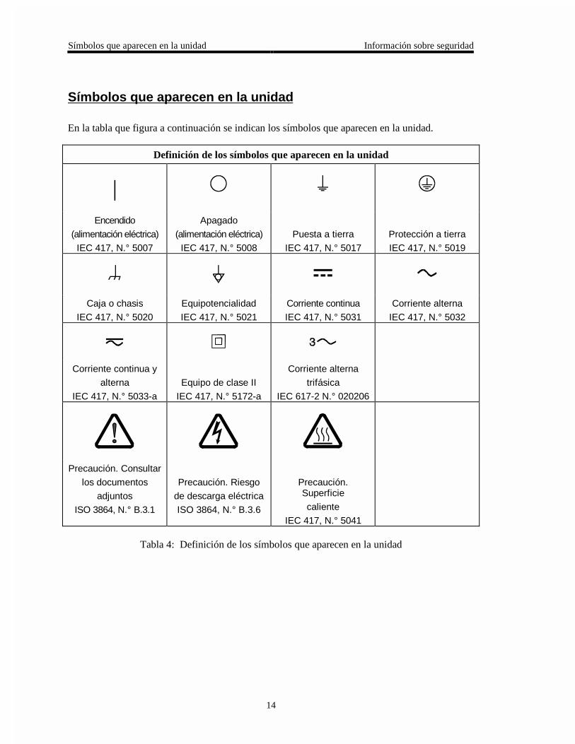
En la tabla que figura a continuación se indican los símbolos que aparecen en la unidad.
Definición de los símbolos que aparecen en la unidad
|Encendido
(alimentación eléctrica)
IEC 417, N.° 5007
Apagado
(alimentación eléctrica)
IEC 417, N.° 5008
Puesta a tierra
IEC 417, N.° 5017
Protección a tierra
IEC 417, N.° 5019
Caja o chasis
IEC 417, N.° 5020
Equipotencialidad
IEC 417, N.° 5021
Corriente continua
IEC 417, N.° 5031
Corriente alterna
IEC 417, N.° 5032
Corriente continua y
alterna
IEC 417, N.° 5033-a
Equipo de clase II
IEC 417, N.° 5172-a
Corriente alterna
trifásica
IEC 617-2 N.° 020206
Precaución. Consultar
los documentos
adjuntos
ISO 3864, N.° B.3.1
Precaución. Riesgo
de descarga eléctrica
ISO 3864, N.° B.3.6
Precaución.Superficie
caliente
IEC 417, N.° 5041
Tabla 4: Definición de los símbolos que aparecen en la unidad

Información sobre seguridad Procedimientos y precauciones de seguridad
15
Procedimientos y precauciones de seguridad
Las precauciones generales de seguridad que figuran a continuación deben observarsedurante todas las fases de funcionamiento del presente instrumento. La no observancia dedichas precauciones, o de las advertencias específicas a las que se hace referencia en elmanual, contraviene las normas de seguridad referentes al uso previsto del instrumento ypodría impedir la protección que proporciona el instrumento. MKS Instruments, Inc., noasume responsabilidad alguna en caso de que el cliente haga caso omiso de estosrequerimientos.
NO UTILIZAR PIEZAS NO ORIGINALES NI MODIFICAR EL INSTRUMENTO
No se debe instalar piezas que no sean originales ni modificar el instrumento sin autorización.Para garantizar que las prestaciones de seguridad se observen en todo momento, enviar elinstrumento al Centro de servicio y calibración de MKS cuando sea necesaria su reparación yservicio de mantenimiento.
REPARACIONES EFECTUADAS ÚNICAMENTE POR TÉCNICOS ESPECIALIZADOS
Los operarios no deben retirar las cubiertas del instrumento. El cambio de piezas y los reajustesinternos deben efectuarlos únicamente técnicos especializados.
PUESTA A TIERRA DEL INSTRUMENTO
Este instrumento está puesto a tierra por medio del conductor de tierra del cable eléctrico. Paraevitar descargas eléctricas, enchufar el cable eléctrico en una toma debidamente instalada, antesde conectarlo a las terminales de entrada o salida del instrumento. Para garantizar el uso sinriesgos del instrumento resulta esencial que se encuentre puesto a tierra por medio del conductorde tierra del cable eléctrico.
PELIGRO POR PÉRDIDA DE LA PUESTA A TIERRA
Si se pierde la conexión protectora de puesta a tierra, todas las piezas conductoras a las que setiene acceso (incluidos los botones y mandos que pudieran parecer estar aislados) podríanproducir descargar eléctricas.
PUESTA A TIERRA Y USO DE ACCESORIOS ELÉCTRICOS ADECUADOS
Este instrumento funciona con voltajes peligrosos. Todos los accesorios y cables eléctricos debenser del tipo especificado y mantenerse en buenas condiciones. Todos los accesorios eléctricosdeben estar conectados y puestos a tierra del modo adecuado.
USAR EL CABLE ELÉCTRICO ADECUADO
Usar únicamente un cable eléctrico que se encuentre en buenas condiciones y que cumpla losrequisitos de alimentación de entrada indicados en el manual.

Procedimientos y precauciones de seguridad Información sobre seguridad
16
Usar únicamente un cable desmontable instalado con conductores que tengan un área de seccióntransversal equivalente o superior a 0,75mm². El cable eléctrico debe estar aprobado por unaentidad autorizada como, por ejemplo, VDE, Semko o SEV.
USAR LA FUENTE DE ALIMENTACIÓN ELÉCTRICA ADECUADA
Este instrumento debe funcionar a partir de una fuente de alimentación eléctrica que no apliquemás voltaje entre los conductores de suministro, o entre uno de los conductores de suministro yla puesta a tierra, que el que se especifica en el manual.
USAR EL FUSIBLE ADECUADO
Usar únicamente un fusible del tipo, clase de voltaje y de corriente adecuados, según lo que seespecifica para el instrumento.
EVITAR SU USO EN ENTORNOS EXPLOSIVOS
Para evitar el riesgo de explosión, no usar este instrumento o en un entorno explosivo, a no serque haya sido certificado para tal uso.
PELIGRO POR ALTO VOLTAJE
Cuando el controlador está encendido, se registra alto voltaje en el cable y en el sensor.
Chapter One: General Information Introduction
17
Chapter One: General Information
Introduction
The MKS Type 270D High Accuracy Signal Conditioner is designed for the MKS 300 and 600Series Baratron high accuracy pressure sensors. Three versions are available with differentdisplay capabilities: a 4½ digit, 5½ digit, and a displayless unit. All versions are designed to fitin a standard ½ rack mount.
The 270 instrument consists of power supplies, an oscillator, and the heater supply necessary tointerface with the compatible MKS 300 Series or 600 Series pressure sensors. The pressure canbe read in mmHg, mbar, kPa, inHg, inH2O, cmH2O, and psi.
The 270 instrument can be combined with the Type 274 multiplexer unit to provide signalconditioning for up to three pressure sensors (from either the 300 or 600 Series, or a combinationof both). The 270 controller interfaces with a pressure sensor through its HEAD andMULTIPLEX connectors.

How This Manual is Organized Chapter One: General Information
18
How This Manual is Organized
This manual is designed to provide instructions on how to set up and install a Type 270 unit.
Before installing your Type 270 unit in a system and/or operating it, carefully read andfamiliarize yourself with all precautionary notes in the Safety Messages and Proceduressection at the front of this manual. In addition, observe and obey all WARNING andCAUTION notes provided throughout the manual.
Chapter One, General Information, (this chapter) introduces the product and describes theorganization of the manual.
Chapter Two, Installation, explains the environmental requirements and describes how to mountthe instrument in your system.
Chapter Three, Overview, gives a brief description of the instrument and its functionality.
Chapter Four, Operation, describes how to use the Type 270 instrument and explains all thefunctions and features.
Appendix A, Product Specifications, lists the specifications of the instrument.
Manual Conventions
The following conventions apply throughout this manual:
XXXXXX For inputs: Indicates that the line must be pulled low to activate the function.
XXXXXX For outputs: Indicates that the output is active low.
Terminology
The term sensor is used throughout the manual to describe a pressure measuring device thatoutputs the raw voltage reading to the 270 signal conditioner. The 270 unit converts the voltagereading into the pressure value. Strictly speaking, a transducer converts the voltage signal into apressure reading and outputs the actual pressure value. A transducer does not require a signalconditioner.

Chapter One: General Information Customer Support
19
Customer Support
Standard maintenance and repair services are available at all of our regional MKS Calibrationand Service Centers, listed on the back cover. In addition, MKS accepts the instruments of othermanufacturers for recalibration using the Primary and Transfer Standard calibration equipmentlocated at all of our regional service centers. Should any difficulties arise in the use of your Type270 instrument, or to obtain information about companion products MKS offers, contact anyauthorized MKS Calibration and Service Center. If it is necessary to return the instrument toMKS, please obtain an ERA Number (Equipment Return Authorization Number) from the MKSCalibration and Service Center before shipping. The ERA Number expedites handling andensures proper servicing of your instrument.
Please refer to the inside of the back cover of this manual for a list of MKS Calibration andService Centers.
Warning All returns to MKS Instruments must be free of harmful,corrosive, radioactive, or toxic materials.
Your 270 instrument can be calibrated with or without the pressure sensor. If you are using your270 instrument with a high accuracy pressure sensor, and the units require calibration, you maywish to return both units to MKS. Calibrating the units together ensures the best possibleaccuracy.

Customer Support Chapter One: General Information
20
This page intentionally left blank.

Chapter Two: Installation How to Unpack the Type 270 Instrument
21
Chapter Two: Installation
How to Unpack the Type 270 Instrument
MKS has carefully packed the Type 270 unit so that it will reach you in perfect operating order.Upon receiving the unit, however, you should check for defects, cracks, broken connectors, etc.,to be certain that damage has not occurred during shipment.
Note Do not discard any packing materials until you have completed yourinspection and are sure the unit arrived safely.
If you find any damage, notify your carrier and MKS immediately. If it is necessary to return theunit to MKS, obtain an ERA Number (Equipment Return Authorization Number) from the MKSService Center before shipping. Please refer to the inside of the back cover of this manual for alist of MKS Calibration and Service Centers.
Caution Only qualified individuals should perform the installation and anyuser adjustments. They must comply with all the necessary ESD andhandling precautions while installing and adjusting the instrument.Proper handling is essential when working with all highly sensitiveprecision electronic instruments.
Parts Checklist
Standard Equipment:
• Type 270 instrumentDisplayless 270-04½ digit display 270-45½ digit display 270-5
• Type 270 Instruction Manual (this book)
• Power Cable CB270-4-xx (where xx = length in feet)
Optional Equipment:
• Electrical Connector Accessories Kit:270D-K1 (includes a mate for the I/O connector)

How to Unpack the Type 270 Instrument Chapter Two: Installation
22
• Connector Cables:
Note Braided, shielded cables may be necessary in noisy environments. Toorder braided, shielded cables, add an “S” after the cable typedesignation. For example, to order a standard connection cable tointerface the Type 270 instrument to a 200 Series controller, use partnumber CB250-7-6; for a braided, shielded cable use part numberCB250S-7-6.
CB270-2-2 and CB-270-4-2: Connect the 270 to a 274 multiplexer unit - bothcables are required
CB250-7-6: Connects the 270 to a 200 Series controllerCB112-12-6: Connects the 270 to a 600 Series controller
• Sensor Head Cables (xx = length in feet):CB270-1-xx: Connects 270, 274, or 670 electronics to 615,
616, 617 sensor headCB270-2-xx Connects 270, 274, or 670 electronics to 590,
690, 698 sensor head
• RM-6 Rack Mount

Chapter Two: Installation Companion Products
23
Companion Products
The 270 instrument works with the following 600 Series pressure sensors:
• 698 Differential Sensor (regulated at 45° C)
• 690 Absolute Sensor (regulated at 45° C)
• 617 Bakeable Fast Absolute Sensor
• 616 Bakeable Differential Sensor
• 615 Bakeable Absolute Sensor
• 590 Absolute Sensor (regulated at 70° C)
The 270 instrument supports the following pressure sensors from the 300 Series:
• 398 Differential Sensor
• 391 Differential Sensor
• 390 Absolute Sensor
• 370 Absolute or Differential Sensor
• 317 Bakeable Fast Absolute Sensor
• 315 Bakeable Absolute or Differential Sensor
• 310 Absolute or Differential Sensor
The range of the full scale pressure sensors can vary from 0.1 to 25K mmHg.
In addition, the 270 instrument can interface with the following units:
• 273 Temperature Controller
• 274 Three Channel Multiplexer Unit
• 275 Set Point Unit
• 232 RS-232C Interface Unit
• 288 IEEE-488 Interface Unit

Product Location and Requirements Chapter Two: Installation
24
Product Location and Requirements
The 270 unit fits in a standard ½ rack mount. It can be mounted in a panel cutout or a 19” rackwhen supplied with the RM-6 Rack Mount option.
Caution Mount the Type 270 instrument in a location with sufficient aircirculation to stay within the specified temperature range.Insufficient air circulation could damage the instrument.
General Requirements
• Operating temperature: 15° to 40° C (59° to 104° F)
• Power: 100, 120, 220, or 240 VAC ±10%, @ 50 to 60 Hz,40 Watt (21 Watts with heater off)

Chapter Three: Overview Front Panel Controls
25
Chapter Three: Overview
Front Panel Controls
Display
PowerSwitch
10-3 and 10-6 Lamps
Sensor Range Switch
Display UnitsSelector Switch
Range Select SwitchSensor Zero Controls
ResponseToggle Switch
HeaterLampHeater
Toggle Switch
Figure 1: Front Panel of the 270-4 Unit
Display
Both the 4½ digit instrument (270-4) and the 5½ digit (270-5) instrument contain an LEDdisplay to display the pressure readings.
The x10-3 and x10-6 Lamps
Neither lamp is included on the displayless unit (270-0). The 270-5 unit contains the x10-3 lamponly. The 270-4 unit has both lamps.
These lamps allow the 270 instrument to display readings between 0.10000 and 0.0010000 withthe use of scientific notation. (The 270 instrument cannot display a decimal point to the left ofthe most significant digit on a full scale reading.) The 270 instrument displays a reading of0.10000 as:
+100.00
with the x10-3 lamp illuminated

Front Panel Controls Chapter Three: Overview
26
SENSOR RANGE Selector Switch
The SENSOR RANGE selector switch is not included on the displayless unit (270-0).
Set the SENSOR RANGE selector switch to match the range of the pressure sensor in use. Thesettings include 1, 10, 100, 1K 10K, and MPX (multiplex connector control). When using the270 unit with a 274 multiplexer, place the SENSOR RANGE selector switch in the MPXposition.
Display Units Selector Switch
The DISPLAY UNITS selector switch is not included on the displayless unit (270-0).
The DISPLAY UNITS selector switch selects the units for the display. The pressure can bedisplayed in inHg, inH2O, mmHg, mbar, kPa, cmH2O, or psi.
RANGE SELECT Switch
The RANGE SELECT switch controls the measurement mode of the instrument. The REMOTE ,x1, x0.1, and x0.01 positions are active measurement ranges while the SYS CHK (systemcheck), NULL and FULL SCALE positions are functional check positions.
NULL(B): When the RANGE SELECT switch is placed in the NULL position, the input to the270 instrument is placed at ground level. Use the NULL control to produce a zero reading onthe front panel display or on an external readout using the DC output signal.
F. S. (Full Scale) (C): The F.S. control calibrates the gain of the 270 instrument to the internalFull Scale. When the RANGE SELECT switch is placed in the FULL SCALE position, the inputto the 270 instrument is connected to an internal calibration signal. This control adjusts the gainof the signal conditioner. Use the FULL SCALE control to produce a full scale (+10 V) signal atthe DC output or the 270 display.
REMOTE: When the RANGE SELECT switch is placed in the REMOTE position, the sensorrange is selected by HEAD RANGE IN TORR switch on a 274 multiplexer.
SYSCHK: Position the RANGE SELECT switch in the SYSCHK position, to troubleshoot the270 unit.
SENSOR ZERO Controls
The SENSOR ZERO C control provides coarse zero adjustment. Use this control to set anapproximate zero setting.
The SENSOR ZERO F control provides high resolution zero adjustment. Use this control to finetune the zero setting. If you cannot adjust the zero setting sufficiently, position the fine controlback to the midpoint and readjust the coarse control.

Chapter Three: Overview Front Panel Controls
27
RESPONSE Toggle Switch
This switch controls the electrical bandwidth of the instrument. The three positions are:
RESPONSE Switch Settings
Setting Hz Milliseconds
FAST 165 1
NORMAL 4 40
SLOW 0.4 400
Table 5: RESPONSE Switch Settings
HEATER Lamp
The HEATER lamp is illuminated when power is applied to the sensor heater.
HEATER Toggle Switch
This switch controls power to the heaters. The switch has two positions: REG and OFF .When the switch is in the REG position, power is applied to the heaters in a sensor to maintaina preset temperature. This minimizes zero and span drift due to ambient temperature variation.This switch is a locking type switch and the handle must be pulled back to change positions.When the switch is in the OFF position, the heaters are not powered.
POWER Switch
This switch controls power to the 270 instrument.
Rear Panel Controls Chapter Three: Overview
28
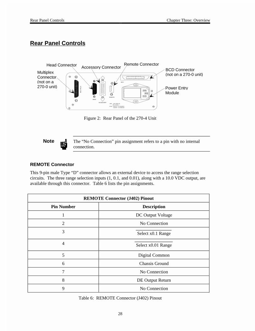
Rear Panel Controls
ACCESSORY
REMOTE
HEAD
BCDM
UL
TIP
LE
X
LINE: +10% 50/60 HZ(50 VA MAX.)
FUSE: 100/120 - 0.6 ASB/250V220/240 - 0.3 ASB/250V
Power EntryModule
BCD Connector(not on a 270-0 unit)
Remote ConnectorAccessory ConnectorHead Connector
MultiplexConnector(not on a270-0 unit)
Figure 2: Rear Panel of the 270-4 Unit
Note The “No Connection” pin assignment refers to a pin with no internalconnection.
REMOTE Connector
This 9-pin male Type “D” connector allows an external device to access the range selectioncircuits. The three range selection inputs (1, 0.1, and 0.01), along with a 10.0 VDC output, areavailable through this connector. Table 6 lists the pin assignments.
REMOTE Connector (J402) Pinout
Pin Number Description
1 DC Output Voltage
2 No Connection
3 Select x0.1 Range
4 Select x0.01 Range
5 Digital Common
6 Chassis Ground
7 No Connection
8 DE Output Return
9 No Connection
Table 6: REMOTE Connector (J402) Pinout

Chapter Three: Overview Rear Panel Controls
29
ACCESSORY Connector
This ribbon connector allows the 270 instrument to interface with accessory units. It provides a0 to 10 VDC output and range ID. Table 7 lists the ACCESSORY connector pinout.
ACCESSORY Connector (J401) Pinout
Pin Number Description
1 DC Output Voltage
2 Remote Zero (Trigger)
3 Digital Common
4 x1 Range ID
5 x0.1 Range ID
6 x0.01 Range ID
7 +5 V
8 DC Output Return
9 No Connection
10 Good Data*
11 +13 V
12 Ground
13 -13 V
14 Chassis Ground
* Used only by MKS
Table 7: ACCESSORY Connector (J401) Pinout
Rear Panel Controls Chapter Three: Overview
30
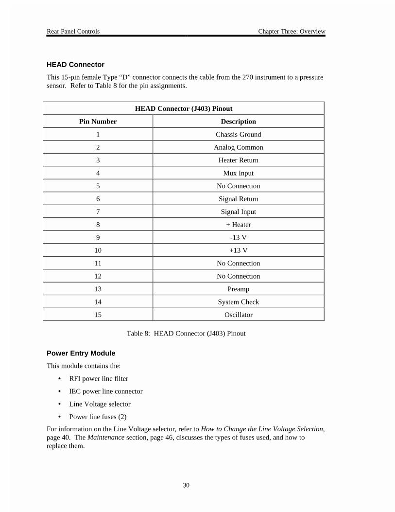
HEAD Connector
This 15-pin female Type “D” connector connects the cable from the 270 instrument to a pressuresensor. Refer to Table 8 for the pin assignments.
HEAD Connector (J403) Pinout
Pin Number Description
1 Chassis Ground
2 Analog Common
3 Heater Return
4 Mux Input
5 No Connection
6 Signal Return
7 Signal Input
8 + Heater
9 -13 V
10 +13 V
11 No Connection
12 No Connection
13 Preamp
14 System Check
15 Oscillator
Table 8: HEAD Connector (J403) Pinout
Power Entry Module
This module contains the:
• RFI power line filter
• IEC power line connector
• Line Voltage selector
• Power line fuses (2)
For information on the Line Voltage selector, refer to How to Change the Line Voltage Selection,page 40. The Maintenance section, page 46, discusses the types of fuses used, and how toreplace them.

Chapter Three: Overview Rear Panel Controls
31
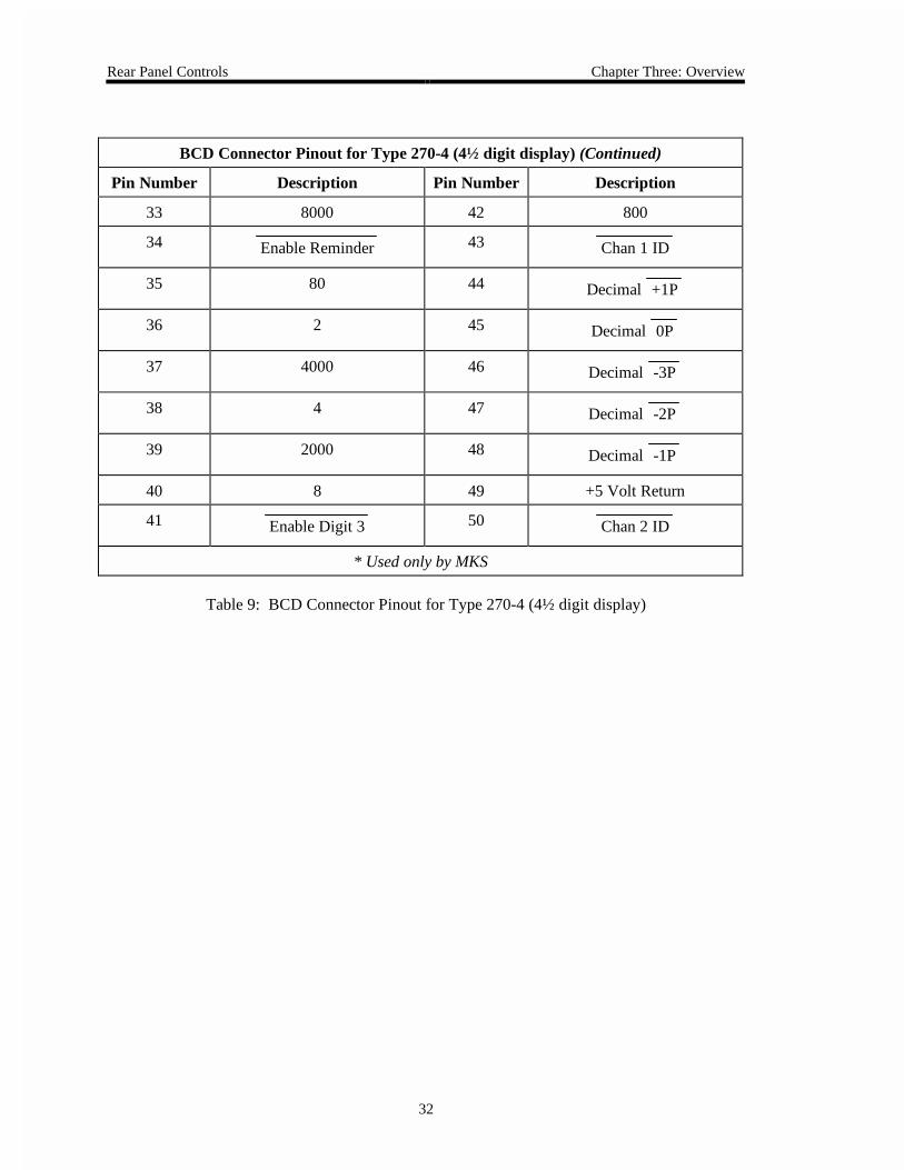
BCD Connector
This connector provides BCD and decimal point outputs. The pin assignments for the 4½ digitdisplay and the 5½ digit display differ. Table 9 lists the pinout for a 4½ digit 270-4 unit; Table10, page 33, lists the pinout for a 5½ digit 270-5 unit.
Note The displayless unit (270-0) does not have a BCD connector.
BCD Connector Pinout for Type 270-4 (4½ digit display)
Pin Number Description Pin Number Description
1 No Connection 17 Enable Digit 1
2 No Connection 18 +5 V @ 25 mA
3 Digital Ground 19 Hold
4 Digital Ground 20 Good Data*
5 10000 21 Decimal +4P
6 No Connection 22 Decimal +3P
7 Enable Digit 2 23 Decimal +2P
8 1 24 Decimal -4P
9 No Connection 25 Chan 3 ID
10 100 26 Overrange
11 200 27 Polarity (+)
12 40 28 Digital Ground
13 400 29 No Connection
14 20 30 Data Ready
15 1000 31 Enable Digit 5
16 10 32 Enable Digit 4
* Used only by MKS
Table 9: BCD Connector Pinout for Type 270-4 (4½ digit display)(Continued on next page)
Rear Panel Controls Chapter Three: Overview
32
BCD Connector Pinout for Type 270-4 (4½ digit display) (Continued)
Pin Number Description Pin Number Description
33 8000 42 800
34 Enable Reminder 43 Chan 1 ID
35 80 44 Decimal +1P
36 2 45 Decimal 0P
37 4000 46 Decimal -3P
38 4 47 Decimal -2P
39 2000 48 Decimal -1P
40 8 49 +5 Volt Return
41 Enable Digit 3 50 Chan 2 ID
* Used only by MKS
Table 9: BCD Connector Pinout for Type 270-4 (4½ digit display)

Chapter Three: Overview Rear Panel Controls
33
BCD Connector Pinout for Type 270-5 (5½ digit display)
Pin Number Description Pin Number Description
1 8000 22 Decimal +3P
2 2000 23 Decimal +2P
3 80000 24 Decimal -4P
4 20000 25 Chan 3 ID
5 Data Ready 26 4000
6 Overrange 27 1000
7 Digital Ground 28 40000
8 800 29 10000
9 200 30 Polarity (+)
10 80 31 100000
11 20 32 Enable BCD
12 8 33 400
13 2 34 100
14 No Connection 35 35
15 No Connection 36 10
16 No Connection 37 4
17 No Connection 38 1
18 +5 V @ 25 mA 39 No Connection
19 Hold 40 No Connection
20 Good Data* 41 No Connection
21 Decimal +4P 42 No Connection
* Used only by MKS
Table 10: BCD Connector Pinout for the Type 270-5(Continued on next page)
BCD Interface Signals Chapter Three: Overview
34
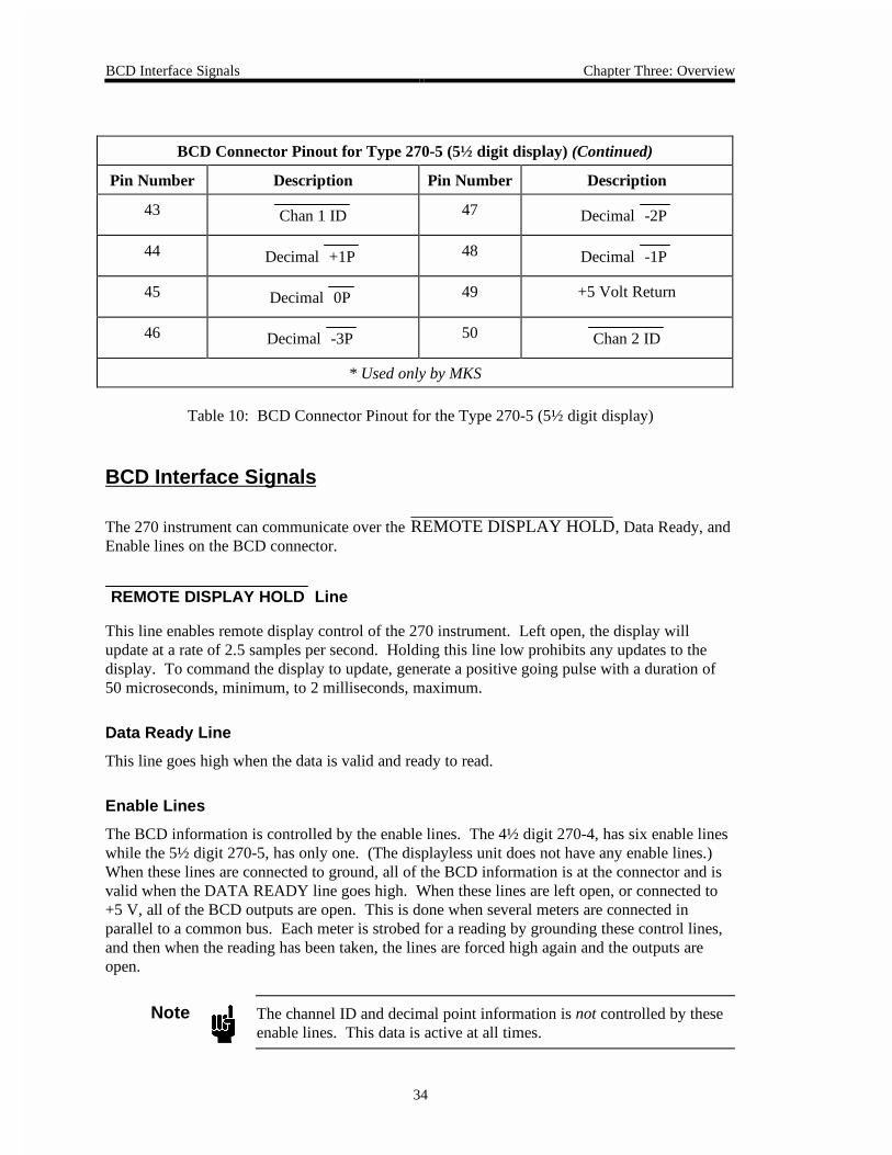
BCD Connector Pinout for Type 270-5 (5½ digit display) (Continued)
Pin Number Description Pin Number Description
43 Chan 1 ID 47 Decimal -2P
44 Decimal +1P 48 Decimal -1P
45 Decimal 0P 49 +5 Volt Return
46 Decimal -3P 50 Chan 2 ID
* Used only by MKS
Table 10: BCD Connector Pinout for the Type 270-5 (5½ digit display)
BCD Interface Signals
The 270 instrument can communicate over the REMOTE DISPLAY HOLD, Data Ready, andEnable lines on the BCD connector.
REMOTE DISPLAY HOLD Line
This line enables remote display control of the 270 instrument. Left open, the display willupdate at a rate of 2.5 samples per second. Holding this line low prohibits any updates to thedisplay. To command the display to update, generate a positive going pulse with a duration of50 microseconds, minimum, to 2 milliseconds, maximum.
Data Ready Line
This line goes high when the data is valid and ready to read.
Enable Lines
The BCD information is controlled by the enable lines. The 4½ digit 270-4, has six enable lineswhile the 5½ digit 270-5, has only one. (The displayless unit does not have any enable lines.)When these lines are connected to ground, all of the BCD information is at the connector and isvalid when the DATA READY line goes high. When these lines are left open, or connected to+5 V, all of the BCD outputs are open. This is done when several meters are connected inparallel to a common bus. Each meter is strobed for a reading by grounding these control lines,and then when the reading has been taken, the lines are forced high again and the outputs areopen.
Note The channel ID and decimal point information is not controlled by theseenable lines. This data is active at all times.

Chapter Three: Overview Overranging Output on the 5½ Digit Unit (270-5)
35
Overranging Output on the 5½ Digit Unit (270-5)
The display on the 270 instrument overranges at 130,000 counts. When the display reaches itsmaximum count, it simply remains locked at that reading. Be wary of readings greater than fullscale on these ranges.
Note The BCD OVERRANGE signal will become active at 130,000 counts.

Overranging Output on the 5½ Digit Unit (270-5) Chapter Three: Overview
36
MULTIPLEX Connector
This 25-pin female Type “D” connector provides access to the logic circuits of the 270instrument. This connector links the 270 instrument with a 274 multiplexer. When the SENSOR
RANGE switch is in the MPX position, the multiplexer controls the placement of the sensorrange and channel ID through this connector. Refer to Table 11 for the pinout of theMULTIPLEX connector.
Note The displayless unit (270-0) does not have a MULTIPLEX connector.
MULTIPLEX Connector (J405) Pinout
Pin Number Description Pin Number Description
1 No Connection 14 No Connection
2 10K 15 No Connection
3 1K 16 No Connection
4 100 17 No Connection
5 10 18 0.1
6 1 19 No Connection
7 No Connection 20 No Connection
8 Chan 1 ID Input 21 Remote Read
9 Chan 2 ID Input 22 Digital Ground
10 Chan 3 ID Input 23 Digital Ground
11 Multiplex Select 24 No Connection
12 No Connection 25 Chassis Ground
13 No Connection
Table 11: MULTIPLEX Connector (J405) Pinout

Chapter Four: Operation How to Configure the 270 Instrument
37
Chapter Four: Operation
How to Configure the 270 Instrument
1. Connect a pressure sensor to the 270 instrument with the appropriate cable.
2. Connect the 270 instrument to any other instrumentation, if applicable.
The upper drawing in Figure 3 shows the correct cables to use to connect the 270instrument to a single pressure sensor and an MKS controller. The lower drawing showsthe Type 270 instrument connected to a Type 274 multiplexer unit.
Type 270 Connected to an MKS Controller
MKS Pressure Controller
CB270-2-xx
300/600 SeriesPressure Sensor
CB250-7-6 / CB112-12-16
Hea
d
Mul
tiple
x
Acc
esso
ry
Rem
ote
Type 270
BCD
CB270-4-2
ELEC
DVM
CH 2 CH 1
REMOTE
CH 3
CB270-2-2
300/600 SeriesPressure Sensor
300/600 SeriesPressure Sensor
Type 274 Type 270
BCD
Rem
ote
Acc
esso
ry
Hea
d
Mul
tiple
x
Type 270 Connected to a Type 274 Multiplexer
Figure 3: Interconnection Cables

How to Configure the 270 Instrument Chapter Four: Operation
38
3. Plug the power cable from the 270 instrument into a 115 VAC - 60 Hz power source.
For a 230 VAC - 50 Hz power source, the power entry module must be set to the propervoltage. Refer to the How to Change the Line Voltage Selection section, beginning onpage 40.
4. Apply power to the 270 instrument by placing the Power switch in the ON position.
5. If you are using the 270 with a single pressure sensor, place the SENSOR RANGE
position the switch in the full scale value of the sensor in use.
If you are using the 270 with the 274 multiplexer unit, position the SENSOR RANGE
switch in the MPX position. Place the HEAD RANGE IN TORR switches, on the 274, tothe full scale value of the sensor in use, for each channel.
6. Position the DISPLAY UNITS selector switch in the mmHg position.
7. If you are using the 270 with a single pressure sensor, place the HEATER switch to theREG position.
If you are using the 270 with the 274 multiplexer unit, place the REG HEATER switches,on the 274, to the ON position. Place the REG switch on the 270 in the OFF
position.
This step applies power to the proportional heater circuit in the sensor. There will be asmall delay between the closing of this switch and the lighting of the HEATER lamp.The lamp will turn on brightly and then, after the sensor warms up, the lamp will go to alower intensity. Allow a minimum of four hours to stabilize a “cold” sensor. If possible,leave the heat on the sensor overnight. For optimal performance, leave the heater onconstantly.
8. Place the RESPONSE switch in the STD position.
The STD position offers the best all-around response versus noise performance forpressure measurement. Select the FAST position when you need a fast (1 millisecond)response. Select the SLOW position when reducing the amount of noise level on theDC output is more important than the system response time.
9. Position the RANGE SELECT switch in the NULL position.
If necessary, adjust the NULL control to produce a zero reading on the front paneldisplay or on an external display.
10. To calibrate the 270 instrument to its internal Full Scale standard, position the RANGE
SELECT switch in the F.S. position.
If necessary, adjust the F.S. control to produce a full scale reading of 10000 on thefront panel display or an external display.
11. Pump the system to a pressure below the resolution of the pressure sensor.

Chapter Four: Operation How to Configure the 270 Instrument
39
12. Position the RANGE SELECT switch in the x0.01 position.
Refer to your sensor’s Instruction Manual for the proper pressure to set the zero. If youare using a differential sensor, crossport the unit.
13. Check the zero reading and adjust if necessary.
If you are using the 270 with a single pressure sensor, use the COARSE and FINE
zero controls on the 270 to adjust the zero reading.
If you are using the 270 with a 274 multiplex unit, use the COARSE and FINE zerocontrols on the 274 multiplexer to adjust the zero reading. Repeat steps 11 through 13for each channel in use.
Note When a 274 multiplexer is attached to the 270 instrument, the zerocontrols on the 274 unit override the controls on the 270 instrument. Usethe zero controls on the multiplexer unit to adjust the zero.
14. Position the RANGE SELECT switch in the x1 position and adjust the NULL pot for azero reading, if necessary.
15. Repeat steps 11 through 14 to produce a zero reading on all ranges.
Note The frequency of setting the zero will depend on the application and itsaccuracy requirements, variations in ambient temperature, and the lengthof time since the instrument zero was last set. For extremely criticalmeasurement of low pressures, check the zero more often and makeminor adjustments, to ensure the most accurate readings.
16. Position the DISPLAY UNITS selector switch in the desired display units.
17. Place the RANGE SELECT switch in the x1 position.
The system is now ready to display the pressure range of the sensor. For ¹/10 of thatrange, use the x0.1 position; for ¹/100 use the x0.01 position.

How to Change the Line Voltage Selection Chapter Four: Operation
40
How to Change the Line Voltage Selection
The 270 instrument can use power from any of the following line voltages:
• 100 VAC
• 120 VAC (factory default setting)
• 220 VAC
• 240 VAC
To change the line voltage:
1. Disconnect the power cord from the 270 instrument.
Warning To avoid an electrical shock, be sure to disconnect thepower cord before proceeding.
2. Disconnect all cables from the connectors located at the back of the unit.
3. Insert a small, flat head screw driver under the left hand side of the black plastic cover,and firmly pull towards you to unsnap the cover.
The cover will flip open, from left to right, to expose the line voltage selector drum and
the two fuse holders. The two fuse holders are marked with up arrows ( ). Note thatthe cover is attached firmly, so it requires a strong force from the screw driver to loosenit.
4. Carefully grasp the line voltage selector drum and pull it out of its position.
5. Turn the selector drum to the appropriate line voltage and re-insert it into the 270instrument so that the voltage value can be read from bottom to top.
The top and bottom of the voltage selector drum are shaped differently so that the drumwill only fit into position in the correct orientation. The value of the selected linevoltage will be visible through the window in the cover when it is closed.

Chapter Four: Operation How to Select the Range Setting Remotely
41
How to Select the Range Setting Remotely
1. Position the RANGE SELECT switch in the REMOTE position.
2. Apply the appropriate signal to select the desired range.
Table 12 lists the logic levels and the corresponding ranges.
Remote Range Logic Levels
Range Remote Connector (J402)
Pin-3 Pin 4
x1 HI HI
x0.1 LO HI
x0.01 HI LO
Table 12: Remote Range Logic Levels
Additional Procedures for the 0.1 Torr Sensors Chapter Four: Operation
42
Additional Procedures for the 0.1 Torr Sensors
The 0.1 Torr sensors require special instructions to adjust the zero setting on the sensor, and touse the remote zero setting on the 270 instrument.
How to Adjust the Zero on the 0.1 Torr Full Scale Sensor
Note 1. Do not attempt to zero a 0.1 Torr Full Scale Type 690 or 698pressure sensor with the Type 270 unit set to the x0.01 range. Thisconfiguration will introduce sufficient noise in the system toexcessively distort the pressure signal and result in linearity and zeroerrors.
2. The x1 and x0.1 ranges operate within the specifications.
To zero a Type 690 or 698 0.1 Torr pressure sensor:
1. Power the sensor and turn on the heater.
2. Pump the unit down to a pressure less than 5 x 10⁻⁷ Torr.
It will take at least 16 hours to establish a good, stable zero reading.
3. Center the COARSE and FINE zero controls.
Turn both controls fully counterclockwise, then turn both controls 15 turns clockwise.
4. Adjust the COARSE zero control on the sensor until the display (or output) is nearlyzero.
The sensor control is located in a hole in the lower loop in the letter “B” in the word“Baratron” on the top of the sensor. This control is a wirewound pot with approximately100 turns. Rather than acting as a potentiometer, this control acts as a 100 positionswitch with about 200 to 1000 ppm F.S. per position (or wire). The stability of thesetting is extremely good if the pot is centered on one wire. Time, temperature changes,or vibration may cause the pot to shift over time. Finding the center of a wire iscomplicated by the variable backlash between the zero control shaft and the wiper. Tofind the center of a wire:
A. Verify that for each revolution of the sensor zero control shaft there are four distinct,stable steps in the 270 instrument display (or output).
Beware of unstable ½ steps. A stable step is one where the output doesn’t changewhile the shaft is turned about ¹/8 turn farther in the same direction.
B. Turn the zero control shaft, in either direction, to the stable step nearest zero andrecord the reading.
It is usually not possible to set the reading to precisely zero because of the resolutionof this control.

Chapter Four: Operation Additional Procedures for the 0.1 Torr Sensors
43
C. Turn the shaft an extra ½ turn in the same direction.
D. Turn the control back slowly until the same output just appears.
E. Carefully turn the shaft an additional ¹/8 turn in the same direction.
This will center the pot in the middle of a step for maximum stability.
Note The above method is the only method that accurately finds the center of awire. The technique of turning the zero control shaft clockwise until itshifts, turning it counterclockwise until it shifts, and positioning itmidway does not work properly.
5. Adjust the COARSE and FINE zero controls on the 270 instrument to bring the display(or output) to precisely zero.
When using the Fine control, you may need to down range the 270 instrument to the x0.1range to make the final setting. Do not use any other range settings.
Using a Low Range Pressure Sensor with the Remote Zero Option
If you are using a pressure sensor less than 1 Torr Full Scale and your 270 instrument is equippedwith the Remote Zero option, you should consult an MKS Service Center. Your 270 instrumentmay need to be modified.
Please refer to the back cover of this manual for a list of the authorized MKS Calibration andService Centers.

Additional Procedures for the 0.1 Torr Sensors Chapter Four: Operation
44
This page intentionally left blank.
Chapter Five: Maintenance and Troubleshooting General
45
Chapter Five: Maintenance and Troubleshooting
General
Should you encounter any difficulties while using your 270 instrument, contact any authorizedMKS Calibration and Service Center. If it is necessary for you to return your instrument, pleaseobtain an ERA (Equipment Return Authorization) Number before shipping. The ERA Numberexpedites handling and ensures proper service of your instrument.
Please refer to the back cover of this manual for a list of the authorized MKS Calibration andService Centers.
Warning All returns to MKS Instruments must be free of harmful,corrosive, radioactive, or toxic materials.

How to Replace the Fuses Chapter Five: Maintenance and Troubleshooting
46
How to Replace the Fuses
The only maintenance required on the Type 270 instrument is changing the fuses. To replace thefuses:
1. Select the proper fuses.
All units have two fuses installed to fuse both sides of the line. The fuse values, markedon the rear panel, are:
• 100/120 VAC = 0.6 Amperes Slow Blow Type
• 220/240 VAC = 0.3 Amperes Slow Blow Type
Refer to Table 13 for a description of the fuses. To change the line voltage selection,refer to the How to Change the Line Voltage Selection section on page 40.
Fuses for the Type 270 Instrument
Nominal Line Line Voltage Range Fuse Type
100 VAC 90 - 110 VAC @50/60 Hz
75 VA (max)
0.63A (T), 250 V,5x20 mm
120 VAC 108 - 132 VAC @50/60 Hz
75 VA (max)
0.63A (T), 250 V,5x20 mm
220 VAC 198 - 242 VAC @50/60 Hz
75 VA (max)
0.315A (T), 250 V,5x20 mm
240 VAC 216 - 264 VAC @50/60 Hz
75 VA (max)
0.315A (T), 250 V,5x20 mm
Table 13: Fuses for the Type 270 Instrument
Note 1. The fuses are IEC rated (where the name plate value is the expectedcurrent carrying rating) and not UL or CSA rated (where the nameplate value is nearly the current blowing rating). Use of UL or CSArated fuses will cause unnecessary blowing at high loads.
2. Appropriate replacement fuses include:
• Bussmann GDC-T315 mA or equivalent for the 0.315 A fuse• Bussmann GDC-T630 mA or equivalent for the 0.63 A fuse

Chapter Five: Maintenance and Troubleshooting How to Replace the Fuses
47
2. Disconnect the power cord from the 270 instrument.
Warning To avoid an electrical shock, be sure to disconnect thepower cord before proceeding.
3. Disconnect all cables from the connectors located at the back of the unit.
4. Insert a small, flat head screw driver under the left hand side of the black plastic cover,and firmly pull towards you to unsnap the cover.
The cover will flip open, from left to right, to expose the line voltage selector drum and
the two fuse carriers. The two fuse carriers are marked with up arrows ( ). Note thatthe cover is attached firmly, so it requires a strong force on the screw driver to loosen it.
5. Carefully slide the fuse carrier out and remove the fuse.
6. Insert the new fuse into the fuse carrier.
Be certain that the new fuse is the appropriate type for the line voltage selection.
7. Slide the fuse carrier back into the Power Entry module.
8. Close the Power Entry module cover.
9. Connect any cables removed from the back of the 270 instrument in step 3 above.
10. Connect the power cord.
Troubleshooting Chapter Five: Maintenance and Troubleshooting
48
Troubleshooting
This section describes the most common problems encountered with the 270 instrument andoffers possible solutions.
Hint: If possible, substitute another similar instrument to verify that the problem involves theType 270 instrument before proceeding.
Overrange (>11 Volts) or Erroneous Pressure Readings
1. Verify that all vacuum fittings are tight and that the sensor is properly pumped down.
Low range absolute sensors (100 mmHg and below) will be overranged at atmosphericpressure.
2. Connect another meter, either analog or digital, to the output to verify that the display ofthe 270 instrument is operating correctly.
3. Place the RANGE SELECT switch in the SYS CHK (System Check) position, theDISPLAY UNITS selector in the MMHG position, and perform the following checks:

Chapter Five: Maintenance and Troubleshooting Troubleshooting
49
Does the SYS CHK (System Check) readproperly? Check the Calibration sheet, sent with your sensor, for the correct system check value.
Problem is in thesensor mechanics
YES
Problem may be in the sensor electronics, the cable, or the 270.Perform Test A, on page 36. Does it pass?
Problem is in thesensor mechanics
YES
Problem may be the cable or the 270.Perform Test B, on page 38. Does it pass?
Problem is in the 270. Place the RANGE SELECTOR in the FullScale position. Does it work properly?
Problem is internal to the 270.Call MKS to receive an ERA number and return the unit.
Problem is in thesensor cable
YES
Problem is in theinput circuits of the 270
YES
NO
NO
NO
NO
Troubleshooting Chapter Five: Maintenance and Troubleshooting
50
Test A: Localizing the Malfunction to the Cable or the Electronics Unit
Equipment Required:
Digital Volt Meter (DVM)
1. Disconnect the sensor cable from the sensor.
2. Place the RANGE SELECT switch in the SYS CHK position.
3. Place the REG switch in the OFF position.
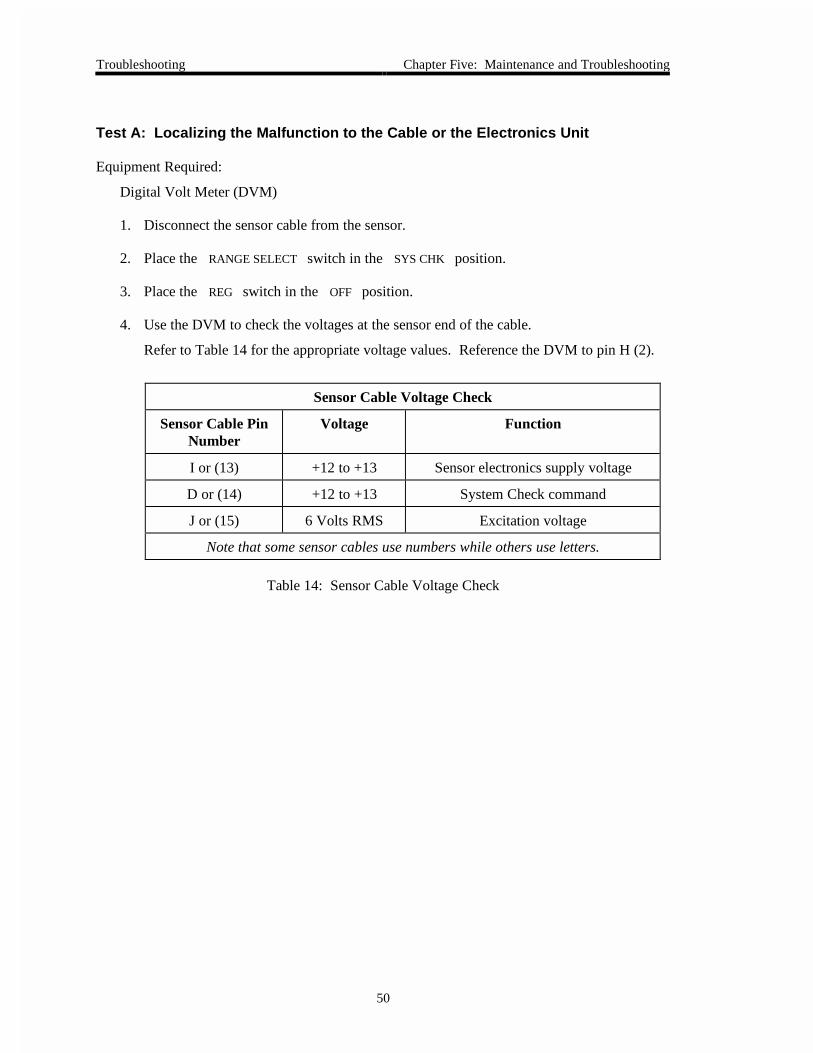
4. Use the DVM to check the voltages at the sensor end of the cable.
Refer to Table 14 for the appropriate voltage values. Reference the DVM to pin H (2).
Sensor Cable Voltage Check
Sensor Cable PinNumber
Voltage Function
I or (13) +12 to +13 Sensor electronics supply voltage
D or (14) +12 to +13 System Check command
J or (15) 6 Volts RMS Excitation voltage
Note that some sensor cables use numbers while others use letters.
Table 14: Sensor Cable Voltage Check
Chapter Five: Maintenance and Troubleshooting Troubleshooting
51
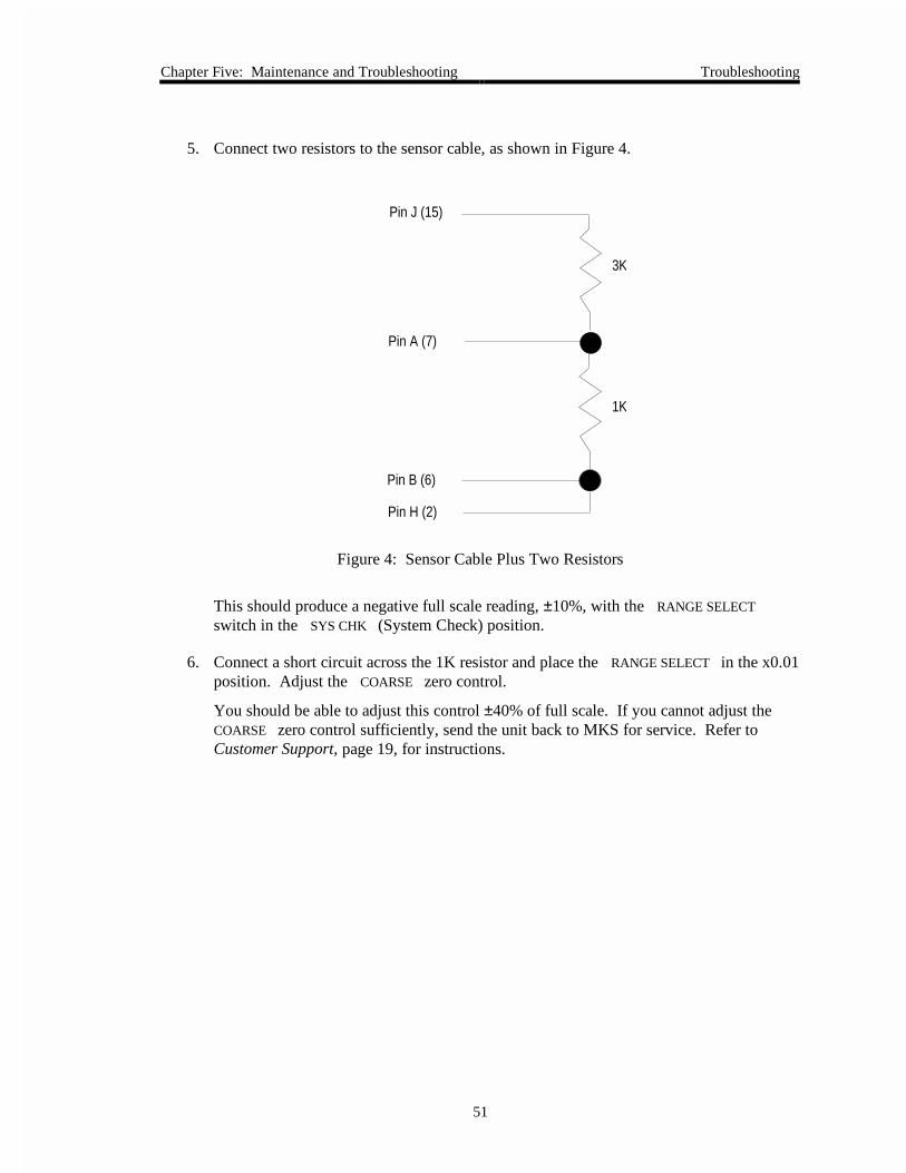
5. Connect two resistors to the sensor cable, as shown in Figure 4.
Pin J (15)
Pin A (7)
Pin B (6)
Pin H (2)
3K
1K
Figure 4: Sensor Cable Plus Two Resistors
This should produce a negative full scale reading, ±10%, with the RANGE SELECT
switch in the SYS CHK (System Check) position.
6. Connect a short circuit across the 1K resistor and place the RANGE SELECT in the x0.01position. Adjust the COARSE zero control.
You should be able to adjust this control ±40% of full scale. If you cannot adjust theCOARSE zero control sufficiently, send the unit back to MKS for service. Refer toCustomer Support, page 19, for instructions.

How to Recalibrate the 270 Unit Chapter Five: Maintenance and Troubleshooting
52
Test B: Localizing Malfunctions to the Electronics Unit
1. Disconnect the sensor cable from the 270 instrument and check voltages at the sensorconnector.
2. Place the RANGE SELECT switch in the SYS CHK position.
3. Place the REG switch in the OFF position.
4. Use the DVM to check the voltages at the sensor end of the cable.
Refer to Table 15 for the correct voltages.
Electronics Unit Voltage Check
Connector Pin Voltage Function
13 +12 to +13 Sensor electronics supply voltage
14 +12 to +13 System Check command
15 6 Volts RMS Excitation voltage
Table 15: Electronics Unit Voltage Check
5. Repeat step 5 of Test A at the sensor connection.
The results should be the same.
How to Recalibrate the 270 Unit
Whenever components have been replaced in the 270 instrument, you must recalibrate theinstrument.
1. Adjust the NULL control to set the zero reading.
2. Place the DISPLAY UNITS selector in the MMHG position.
3. Position the RANGE SELECT switch in the F.S. position and adjust for +10000 ±0.01% (100000 for the 270-5).

Chapter Five: Maintenance and Troubleshooting Appendix A: Product Specifications
53
Appendix A: Product Specifications
All specifications are at 23° C, 120 VAC
Analog Output
Output Linearity
Accuracy (includesnon-repeatability)
x1 Range
x0.1 Range
x0.01 Range
Output Impedance
Output Noise
0.01 - 0.4 Hz
1 kHz - 1 MHz
0 to ±10 V on each range, into >10K ohms load,available at rear connectors
±(0.005% of reading +0.001% of full scale)
100 ppm of reading
300 ppm of reading
500 ppm of reading
<1 ohm
< 70 µVolts peak-to-peak on x1 and x0.1 ranges< 350 µVolts peak-to-peak on x0.01 range
<4 mVolt peak-to-peak
BCD Outputs (270-4 and 270-5 only)
Pressure Information
Decimal points, channel IDrange ID outputs
Output Drive Ability
parallel line 3 state logic
buffered TTL levels
1 TTL load
Electromagnetic Compatibility1 EMC Directive 89/336/EEC
Dimensions Standard MKS ½ rack, 3½” H x 9½” W x 12” D(8.9 cm H x 24.1 cm W x 30.5 cm D)
Display
Linearity
Update Rate
270-0 no display270-4 4½ digit display (½” red segment LED)270-5 5½ digit display (½” red segment LED)
270-4 ±0.01% of reading ±1 count270-5 ±0.001% of reading ±1 count
270-4 2.5 readings per second270-5 1.4 readings per second
(Table continued on next page)
1 Requires an overall metal braided shielded cable, properly grounded at both ends, during use.
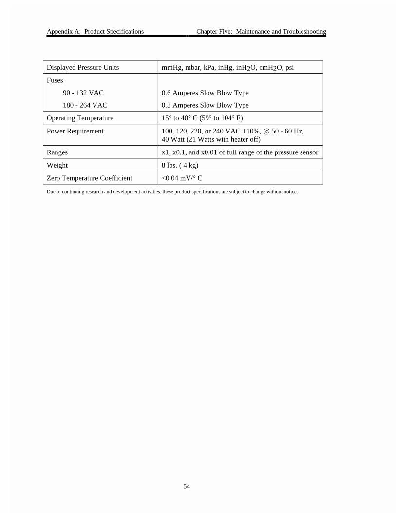
Appendix A: Product Specifications Chapter Five: Maintenance and Troubleshooting
54
Displayed Pressure Units mmHg, mbar, kPa, inHg, inH2O, cmH2O, psi
Fuses
90 - 132 VAC
180 - 264 VAC
0.6 Amperes Slow Blow Type
0.3 Amperes Slow Blow Type
Operating Temperature 15° to 40° C (59° to 104° F)
Power Requirement 100, 120, 220, or 240 VAC ±10%, @ 50 - 60 Hz,40 Watt (21 Watts with heater off)
Ranges x1, x0.1, and x0.01 of full range of the pressure sensor
Weight 8 lbs. ( 4 kg)
Zero Temperature Coefficient <0.04 mV/° C
Due to continuing research and development activities, these product specifications are subject to change without notice.

Index
55
Index
0
0.1 Torr sensors, using, 42–43
A
Accessories, optional, 21
ACCESSORY connector, 29
B
BCD, 31–34
C
Communications, 34
Data Ready line, 34
Enable line, 34
Remote Display Hold line, 34
Companion products, 23
Customer support, 19
D
Data Ready line, 34
Digital readout, 25
DISPLAY UNITS switch, 26
E
Enable line, 34
F
Front panel, 25–27
Fuses, 46
H
HEAD connector, 30
HEATER lamp, 27
HEATER switch, 27
I
Introduction, 17
L
Line voltage, changing, 40
Location requirements, 24
M
Maintenance, 46
Manual
conventions, 18
organization, 18
terminology, 18
MULTIPLEX connector, 36
P
Power entry module, 30
POWER switch, 27
R
RANGE SELECT switch, 26
Range setting, remotely, 41
Rear panel, 28–34
Recalibration, 52
REMOTE connector, 28

Index
56
Remote Display Hold line, 34
RESPONSE switch, 27
Returns, 19, 45
S
Scientific notation, lamps for, 25
SENSOR RANGE switch, 26
SENSOR ZERO controls, 26
Setup, 37–39
Specifications, 53–54
T
Type 274 Multiplex unit, 17, 36, 37–39
Z
Zero control, 26