mmf experiment no 1
TRANSCRIPT

8/6/2019 Mmf Experiment No 1
http://slidepdf.com/reader/full/mmf-experiment-no-1 1/15
MECHANICS OF METAL FORMING
Jayesh Desai Page 1
EXPERIMENT NO: 1
AIM: Basics of metal forming
Q-1 State the fundamental conditions for stress stress relations in
plastic deformation.
Ans…. The fundamental conditions for stress and strain are as follows.
(1) in any plastic deformation process the work done is always positive. For example-if a
specimen is extended, positive work is done, if it is compressed again positive work is done.
(2) Plastic deformation takes place only when the stress increment vector at a point on
the yield surface is directed outside the yield surface.
(3) If the body is in plastic state i.e. the stress point is on the yield surface and the stressincrement is directed along the tangent to the yield surface, or the stress point simply
moves on the yield surface, then no plastic deformation on take place.
Q-2 Explain the normality rule related to plastic stress strain
relation.Ans….
the strain increment or strain rate in plastic deformation are proportional to the
corresponding deviator stress components.
From the plastic stress strain condition it is clear that the angle between the stress
vector and the strain vector must always be acute only then the plastic work done is always
positive.From the second and third conditions it is clear that the stress increment may be in
any direction pointing outside the yield surface, the strain increment vector should always be
directed along the normal to the yield surface at the point of application of stress increment,
which is also the direction of deviator component of stress tensor. This is called the normality
rule.
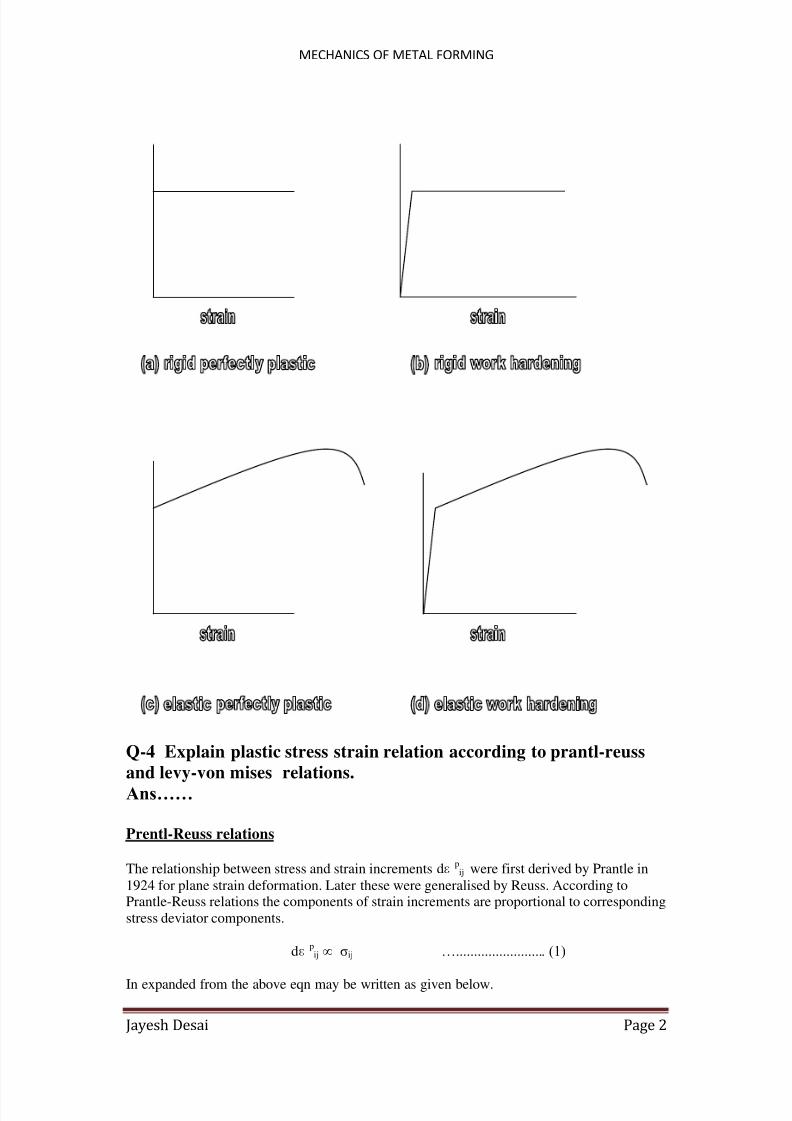
Q-3 Differentiate following related to plastic stress strain relations.
(a) rigid perfectly plastic material.
(b) rigid work hardening material.
(c) elastic perfectly plastic material.(d) elastic work hardening material.
Ans…… If the material does not work harden it is called rigid perfectly plastic material.
If the material does work harden it is called rigid hardening material.If the elastic deformation taken into account and material does not work harden it is
called elastic perfectly plastic material.
If the material does work harden in elastic deformation it is called elastic work
hardening material.
The difference is illustrated in fig idealized stress strain relations.
8/6/2019 Mmf Experiment No 1
http://slidepdf.com/reader/full/mmf-experiment-no-1 2/15
MECHANICS OF METAL FORMING
Jayesh Desai Page 2
Q-4 Explain plastic stress strain relation according to prantl-reuss
and levy-von mises relations.Ans……
Prentl-Reuss relations
The relationship between stress and strain increments dɛpij were first derived by Prantle in
1924 for plane strain deformation. Later these were generalised by Reuss. According toPrantle-Reuss relations the components of strain increments are proportional to corresponding
stress deviator components.
dɛpij ∞ σij …......................... (1)
In expanded from the above eqn may be written as given below.

8/6/2019 Mmf Experiment No 1
http://slidepdf.com/reader/full/mmf-experiment-no-1 3/15
MECHANICS OF METAL FORMING
Jayesh Desai Page 3
dɛp11 ∞ σ11 ……………………..(2)
dɛp22 ∞ σ22 ……………………..(3)
dɛp33 ∞ σ33 ……………………..(4)
dɛp12 ∞ σ12 ……………………..(5)
dɛp23 ∞ σ23 ………………………(6)
dɛ p31 ∞ σ31 ………………………(7)
the relations may be written as,
dɛpij ∞ dΦσij ……………………….(8)
where dΦ is a factor of proportionality. These relations may be put in the following form.
dɛpij = (3/2)( dɛ
pij /σ)σij ……………………….(8)
Levy-Von Mises relations
The levy-von mises relations are similar to that of Prantl-Reuss. In these relations
the elastic increments are neglected .Its taken that strain increments are entirely
plastic increments. Hence
dɛpij = (3/2)( dɛ
pij /σ)σij …………………………(9)
and also σ = σ0
Stress Strain relations
The relationship between stresses and plastic strain rates may be written as below.
ɛpij = Φσij ………………………….(10)
In the expanded form these may be written as
ɛp11 ∞ Φσ11
= Φ(2σ11- σ22 – σ33)/3 …………………………..(11)
ɛ p22 ∞ Φσ22 = Φ(2σ22- σ11 – σ33)/3 …………………………..(12)
ɛp33 ∞ Φσ33
= Φ(2σ33- σ11 – σ22)/3 …………………………..(13)
ɛp12 = Φσ12 = Φσ12 ……………………………(15)
ɛp23 = Φσ23 = Φσ23 ……………………………(16)
ɛp31 = Φσ31 = Φσ31 ……………………………(17)

8/6/2019 Mmf Experiment No 1
http://slidepdf.com/reader/full/mmf-experiment-no-1 4/15
MECHANICS OF METAL FORMING
Jayesh Desai Page 4
Here Φ is the factor of proportionality. It is not constant. Multiplying both sides of eqn(11) by
it self we get Φ as below.
ɛpij ɛ
pij = Φ2 σij σij
also
σij σij = 2 K2 = 2/3 σ0
2
Therefore
Φ = √ ɛ ij ɛ ij / √2 K ………………………...(18)
Q-5 What do you meant by yield condition?
Ans……
A yield criterion is a postulated mathematical expression of the states of stress that will cause
yielding. The most general form is
f (σx ,σy ,σz ,τyz ,τzx ,τxy ) = C …………………………(1)
For isotropic materials, this can be expressed in terms of principal stresses as
f (σ1,σ2,σ3) = C ………………………….(2)
Formost isotropic ductilemetals the following assumptions are commonlymade:
1. The yield strengths in tension and compression are the same. That is, any
Bauschinger∗ effect is small enough so it can be ignored.
2. The volume remains constant during plastic deformation.
3. The magnitude of the mean normal stress,
σm = σ1 + σ2 + σ3/3 …………………………….(3) does not affect yielding.
The yield criteria to be discussed involve these assumptions. Effects of temperature,
prior straining, and strain rate will be discussed in later chapters.The assumption that yielding is independent of σm is reasonable because defor -mation usually occurs by slip or twining, which are shear mechanisms. Therefore the
yield criteria for isotropic materials have the form
f [(σ2 − σ3), (σ3 − σ1), (σ1 − σ2)] = C ………………………….(4)
This is equivalent to stating that yielding depends only on the size of theMohr’scircles
and not on their positions. Figure 2.1 shows this. If a stress state σ1,σ2,σ3 will cause
yielding, another stress state,
σ1 = σ1 - σm
σ2 = σ2 - σm
σ3 = σ3 - σm

8/6/2019 Mmf Experiment No 1
http://slidepdf.com/reader/full/mmf-experiment-no-1 5/15
MECHANICS OF METAL FORMING
Jayesh Desai Page 5
that differs only by σm,will also cause yielding. The stresses σ1, σ2 , σ3 are called deviatoric
stresses.
Q-6 Derive the relationship between yield strength in shear and yield
strength in tension according to Von-Mises hypothesis.
Ans….
Von-Mises criteria takes into account from the eqn of yield criteria.
II = K
2 …………………………..(1)
Wherw K is the constant which may be rekated to material properties. The details are
discussed below.
A stressed metal body reaches the yield point if the following eqn is satisfied.
(σ11 - σ22)2 + (σ22 – σ33)2 + (σ33 – σ11)2 +6 (σ122
+ σ232
+ σ312
) = 6K2 ………..(2)
In the principal stresses σ1, σ2 and σ3 , The eqn (1) reduces to the following form.
(σ1 - σ2)2 + (σ2 – σ3)2 + (σ3 – σ1)2= 6K2 ……………………(3)
The value of K may be determined from the uniaxial tension or compression test, in which
case, we may take that σ1ǂ 0, while the other two principal stresses equal to zero. We put
these value in eqn (3) . also we know that yielding takes place only when σ1 = σ0 = yield
strength of material in tension thus,
2 σ12 = 2 σ0
2= 6K
2 ………………………….(4)
Therefore,
K= σ0/√3 ………………………….(5)
Value of K may also be determined by experimenting with a different state of stress. Thus by
subjecting a thin tube to torsion we may create a condition for pure shear.by increasing the
torsion and hence shear stress the material of the tu be is brought to the yield point. Let σ12 be
the shear stress due to the torsion and let Ʈ 0 be the yield strength of the material in shear . by
substituting σ12 = Ʈ 0 and all other stress components equal to eqn(2), we get the following .
K = Ʈ 0 = yield strength of material in shear……………………..(6)
From eqn (4) and (5) it is obvious that,
Ʈ 0 = σ0/√3 ………………………….(7)

8/6/2019 Mmf Experiment No 1
http://slidepdf.com/reader/full/mmf-experiment-no-1 6/15
MECHANICS OF METAL FORMING
Jayesh Desai Page 6
Eqn (7) gives a relationship between the yield strength of material in shear to its yield
strength in tension.
Q-7 Derive the relationship between yield strength in shear and yieldstrength in tension according to Tresca’s hypothesis.
Ans….
A metal body reaches the yield point when the maximum shear stress in the body
reaches the value equal to the yield strength of the metal in shear.
If the stress state is given by three principal stresses σ1, σ2 and σ3 the maximum shear
stress are as follows.
Ʈ 1 max = ½ (σ1 - σ2)
Ʈ 2 max = ½ (σ2 – σ3)
Ʈ 3 max = ½ (σ3 – σ1)
Out of these three we can evaluate the greatest value of shear stress if we know the
relative magnitudes of the principal stresses. Let us takes that σ1> σ2 > σ3 then the greatest
value of shear stress is givaen by
Ʈ max = ½ (σ1 – σ3)
According to tresca’s hypothesis the metal body will be in plastic state if
½ (σ1 – σ3) = Ʈ 0
Where Ʈ 0= yield strength of the material in shear.
In tension test we may take that σ1ǂ 0 while all other stress components are zero.The yielding
occurs when σ1 = σ0 = yield strength of material in tension. Also we know that in case of
uniaxial tension the greatest value of shear stress is equal to half the tensile stress. Therefore
at the yield point,
Ʈ 0 = σ0/2 ………………………….(1)
Thus according to tresca’s hypothesis , the yield strength in shear is equal to half the yield strength in tension while according to van-mises its equal to
Ʈ 0 = σ0/√3.
Tresca’s hypothesis may also be written in the gener alised form as given below.
[(σ1 - σ2)2 - 4 Ʈ 02
] [(σ2 – σ3)2- 4 Ʈ 02
] [(σ3 – σ1)2- 4 Ʈ 02
]= 6K2 …(2)
8/6/2019 Mmf Experiment No 1
http://slidepdf.com/reader/full/mmf-experiment-no-1 7/15
MECHANICS OF METAL FORMING
Jayesh Desai Page 7
Q-8 Give out the graphical 3 dimensional representation of yield
crieteria.
Ans…
The graphical representation gives a better understanding of two yield criteria
von-mises and tresca’s hypothesis. For convenience we take the coordinate axes along the
three principal stresses σ1, σ2 and σ3 .
In these coordinate system, any stress state given by a set of three principal
stresses σ1, σ2 and σ3 is represented by a point. Von mises yield criteria is represented by a
cylindrical surface while tresca’s criteria represented by hexagonal prism.
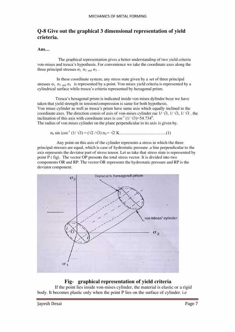
Tresca’s hexagonal prism is indicated inside von mises dylinder bcoz we havetaken that yield strength in tension/compression is same for both hypothesis.
Von mises cylinder as well as tresca’s prism have same axis which equally inclined to the
coordinate axes. The direction consis of axis of von-mises cylinder rae 1/ √3, 1/ √3, 1/ √3 . theinclination of this axis with coordinate axes is cos-1 (1/ √3)=54.7340
.The radius of von mises cylinder on the plane perpendicular to its axis is given by,
σ0 sin (cos-1
(1/ √3) = (√2 /√3) σ0 = √2 K……………………………(1)
Any point on this axis of the cylinder represents a stress in which the three
principal stresses are equal, which is case of hydrostatic pressure .a line perpendicular to the
axis represents the deviator part of stress tensor. Let us take that stress state is represented bypoint P ( fig). The vector OP presents the total stress vector. It is divided into two
components OR and RP. The vector OR represents the hydrostatic pressure and RP is the
deviator component.
Fig- graphical representation of yield criteria
If the point lies inside von-mises cylinder, the material is elastic or a rigidbody. It becomes plastic only when the point P lies on the surface of cylinder. i.e

8/6/2019 Mmf Experiment No 1
http://slidepdf.com/reader/full/mmf-experiment-no-1 8/15
MECHANICS OF METAL FORMING
Jayesh Desai Page 8
when the stress state satisfies . points outside the cylinder are not defined. It is taken
that the material will suffer plastic deformation when P is on the cylinder and stress
increment is directed outside the cylinder. A similar discussion applies to tresca’shexagonal prism as well.
Both the yield conditions show that hydrostatic pressure, whatever its value,cannot bring a metal body to the yield point. Because in that condition the stress point
will lie on the axis of yield surface and not its surface.
Fig- Von mises’s yield condition & stress at a point
Now if the stress point P lies on the yield surface and stress increment is directed
tangentially to yield surface we shall only be moving from one state of yielding to another
state of yielding and hence no plastic deformation occurs, plastic deformation occurs only
when the incremental stress vector is directed out side von-mises ‘ cylinder or tresca’shexagonal prism.
Q-9 Explain about any one factor which affect the yield strength.

8/6/2019 Mmf Experiment No 1
http://slidepdf.com/reader/full/mmf-experiment-no-1 9/15
MECHANICS OF METAL FORMING
Jayesh Desai Page 9
Ans…….
The yield strength of the of a metal or alloy is affected by following factors.
(1) Strain hardening.
(2) Strain rate.(3) Temperature of metal and microstructure.
(4) Hydrostatic pressure.
Effect of hydrostatic pressure
Hydrostatic pressure may affect the following properties of metals and hence their
formability.
(1) Ductility
(2) Yield strength of flow stress.(3) Strain hardening and strain rate index.
Experiments of bridgeman have shown that hydrostatic pressure does not lead to
plastic deformation. However, hydrostatic pressure increases the ductility and formability of metals and alloys. The phenomenon of increased ductility with hydrostatic pressure is also
called pressure indused ductility.
Fig- effect of hydrostatic pressure on yield strength of quenched and tempered AISI4330 steel

8/6/2019 Mmf Experiment No 1
http://slidepdf.com/reader/full/mmf-experiment-no-1 10/15
MECHANICS OF METAL FORMING
Jayesh Desai Page 10
Even brittle materials may be plastically deformed under suitable hydrostatic
pressure. Materials in which the plastic deformation leads to change in volume, the yieldstrength may be affected by hydrostatic pressure. Spitzig have shown that yield strength of
quenched and tempered AISI 4310 and 4330 steels is affected by hydrostatic pressure.
In Fig shows the effect of hydrostatic pressure on the yield strength of 4330 steel.Both the steels show increase in volume during plastic deformation as well as increase in
yield strength under hydrostatic pressure. Very few researchers have attempt to determine the
effect of hydrostatic pressure on strain hardening and strain rate effect indices. According tospitzig , there is no effect of hydrostatic pressure on the strain hardening index.
Q-10 why most of metals obey von-mises yield criteria? Explain it.
Ans…..
Several methods have been used to verify the two criteria of yielding metals.According to them we have take the taylor and quinney. In this method a tube of metal to be
tested , is loaded by a couple to produce shear stress and direct axial force is applied metal tobe tested , is loaded by a couple to produce shear stress and direct axial force is applied to
produce axial tension.
Thus different combinations of direct stress and shear stress values which can
produce yielding of metal aer obtained. Let the axial force produce a direct axial stress σ andthe couple produce a shear stress Ʈ . The principal stresses σ1, σ2 and σ3 may be determined as
given below.
σ3 = 0 …………………………..(1)
and
σ1, σ2 = σ/2 ± [ ( σ/2 )2+ Ʈ 2
]1/2 ………………………(2)
now according to tresca’s hypothesis of yielding the maximum shear stress shouldbe equal to yield strength of metal in shear. In above case σ1 > σ2 > σ3 .
The greatest shear stress is given by
( σ1- σ2 ) / 2 = [ ( σ/2 )2+ Ʈ 2
]1/2
Therefore,
[ ( σ/2 )2+ Ʈ 2
]1/2
= Ʈ 0 = σ0 /2
Taking square of both sides and rearranging the terms we get,
( σ/σ0)2
+ 4 ( Ʈ /σ0)2 = 1 …………………… (3)
It is an eqn of ellipse. Similarly by putting σ and Ʈ in von-mises hypothesis we get
( σ/σ0) + 3 ( Ʈ /σ0)2 = 1 ………………………………(4)
This is also an eqn of ellipse eqn (2) and (3) are plotted in fig for sake of compression.

8/6/2019 Mmf Experiment No 1
http://slidepdf.com/reader/full/mmf-experiment-no-1 11/15

8/6/2019 Mmf Experiment No 1
http://slidepdf.com/reader/full/mmf-experiment-no-1 12/15
MECHANICS OF METAL FORMING
Jayesh Desai Page 12
Fig. – Inclined plane in space of principal stresses.
From above three equations we can also solve for the three variables n12 , n2
2 and n32. let us
take that
1 1 1
σ 1 σ 2 σ 3 = ∆
σ 12 σ 2
2 σ 32
Now we can determine n12 , n2
2 and n32 as given below.
1 1 1
n12
= 1/ ∆ σ 2 σ 3 σ n σ 2
2 σ 3
2 σ n
2+ σ s
2
1 1 1
n2
2
= 1/ ∆ σ 3 σ n σ 1 σ 32 σ n
2+ σ s
2 σ 12

8/6/2019 Mmf Experiment No 1
http://slidepdf.com/reader/full/mmf-experiment-no-1 13/15
MECHANICS OF METAL FORMING
Jayesh Desai Page 13
1 1 1
n32 = 1/ ∆ σ 3 σ n σ 2
σ n2
+ σ s2 σ 1
2 σ 22
The above equations for n12 , n2
2 and n32 can be written in the following form after
simplification.
[ σ n_
1/2 ( σ 2 + σ 3 ) ]
2+ σ s
2= n1
2( σ 2
_ σ 3 ) ( σ 2
_σ 3 ) + 1/4 ( σ 2
_σ 3 )
2 ……(4)
[ σ n_
1/2 ( σ 1 + σ 3 ) ]
2+ σ s
2= n2
2( σ 2
_ σ 3 ) ( σ 2
_σ 1 ) + 1/4 ( σ 3
_σ 1 )
2…….(5)
[ σ n_
1/2 ( σ 1 + σ 2 ) ]
2+ σ s
2= n3
2( σ 3
_ σ 1 ) ( σ 3
_σ 2 ) + 1/4 ( σ 1
_σ 2 )
2…….(6)
The Eqns (4) ,(5) and (6) are in fact equations of circles if we take σ n and σ s as variables.
For instance the corresponding to Eqn, (4) has its centre [1/2 ( σ 2 + σ 3 ), 0] and radius equal
[( σ 2 _
σ 3 ) ( σ 2 _
σ 3 ) + 1/4 ( σ 2 _
σ 3 )2]
1/2
Two dimensional Mohr’s Stress Cricle.
Two dimensional cases arise, when the inclined plane is normal to X 1 or X 2 or X 3, forinstance, let the plane be normal to X 1, i.e. n1 = 0. The Eqn.(4) converts into a two
dimensional Mhor’s circle giving relationship between σ 2 and
σ 3 . All the three two
dimensional-cases that arise when the inclined plane becomes normal to one of the axes are
discussed below.
When n1 = 0, Moher’s circle equation become
[ σ n_
1/2 ( σ 2 + σ 3 ) ]
2+ σ s
2= 1/4 ( σ 2
_σ 3 )
2 …………………………………(7)
Similarly When n2 = 0 , the inclined plane is normal to X 2 ,the equation for Moher’s stresscircle is given by following equation.
[ σ n _ 1/2 ( σ 1 + σ 3 ) ] 2 + σ s2 = 1/4 ( σ 3 _ σ 1 ) 2 …………………………………(8)
Similarly When n2 = 0, Moher’s circle equation become
[ σ n_
1/2 ( σ 1 + σ 2 ) ]
2+ σ s
2= 1/4 ( σ 1
_σ 2 )
2 …………………………………(9)
The Enq. (9) can be conveniently represented graphically as shown in Fig(3.6). now if n1
= cos θ then n2 = sin θ , n3 = 0. Therefore, the normal stress on the inclined plane (see Fig 3.6)
become,
σ n = σ 1 n12+ σ 2 n2
2
= σ 1 cos θ 2+ σ 2 sin θ 2

8/6/2019 Mmf Experiment No 1
http://slidepdf.com/reader/full/mmf-experiment-no-1 14/15

8/6/2019 Mmf Experiment No 1
http://slidepdf.com/reader/full/mmf-experiment-no-1 15/15