moberly, duerig, proft, sinclair martensitic transformations ii
TRANSCRIPT
25 March 2009 NDC Business System R2Letterhead (scale 80%) Option #1
47533 Westinghouse Drive Fremont, California 94539 t 510.683.2000 f 510.683.2001
We are Nitinol.™
www.nitinol.com
TwinlessMartensiteinTiNiCuShapeMemoryAlloys
Moberly,Duerig,Proft,Sinclair
MartensiticTransformationsII(ed.)B.C.Muddle
MaterialsScienceForumVols.56‐58pp.605‐610
1990
MuurUJIs Science Forvm Vois. 56 - 58 (1990) pp. 605-610 Copyrlglu Trans Tech PubIicalWIIS, Swlturland
TWINLESS MARTENSITE IN TiNICu SHAPE MEMORY ALLOYS
W.J. Moberly (a), J .L. Proft (b), T.W. Duerig (b) and R. Sinclair (a) (a) Dept. 01 Matenals Scieoc:e & Engineering, Stanford University
Stanford, CA 94305, USA (b) Raychem CorporatiOn, MenlO Pal1!., CA 94025, USA
ABSTRACf
Martensitic transformations generally resull in a lauice invariant shear such as twinning. TiNi shape memory alloys typically exhibit submicron twinning upon ttansfonning from high temperature cubic austenite to low temperature monoclinic martensite. Previous studies have discussed the presence of (111), (all) and (010) twinning in the martensite of the binary alloy. The substitution of between 15% and 30% Cu for Ni results in a ternary aUoy having the same B2 austenite structure but an orthorhombic martensite structure. Although many orthorhombic grains exhibit (01 1) twinning, some grains exhibit no twinning. The crystallographic nature of this twinless martensite based on transmission e lectron microscopy (TEM) observations and x-ray diffrac tion (XRD) will be discussed. In situ TEM heating and cooling experiments are conducted in an attempt to establish the orientation relationships between the austenite and martensite phases. A simple mathematical transformation may explain how the twinless orthorhombic structure is derived from the parent cubic phase. In addition, the shape memory aspects of these ternary alloy are discussed.
1. INTRODUCfION
Binary TiNi has been extensively studied, both with regards to its shape memory properties and the crystallography of its martensitic transfonnation [1 -4]. Upon cooling, the cubic, B2 austenitic structure transforms to monoclinic, B19' martensite [4,5]. The martensite typically exhibits fine submicron twinning, with the monoclinic (Ill), (all) and (010) twin planes being observed [6,7,8]. Kno~les and Smith [8] have applied the martensitic transfonnation theories of Wechsler, Lieberman and Read [9, 10] to the binary TiNi system. Although the addition of third elements onen sttongly alter the martensiric uansformation temperature Ms, the addilion of Cu has been shown to have little effect on Ms [tIl. Generally only small ternary additions may be made without changing the crystallographic structures and diminishing or cancelling the shape memory effect. However, up to 30% Cu may be substituted for Ni and still retain the shape memory properties. Whereas the austenite structure remains B2 as eu is added [I2], the martensitic structure changes for higher Cu
606 MOBERLY 8t al.
(>10%) Icmary alloys. Both monoclinic [13] and onhorhombic [1 4] manensiles have been observed for ternary alloys containing 15-25% Cu. Although the equilibrium rnlU'tensite struclUre of Ihe higher Cu alloys is determined 10 be onhorhombic, Ihe structure also appears to depend on processing [IS ). Ternary alloys containing - 10% Cu undergo two marlensilic transformalions upon cooling. with an onhorhombic manensite presenl over a JO 0_ 20°C range prior to transforming to monoclinic martensite [15,16,17]. The present analysis considers the various twinning systems observed in the Cu contain ing alloys and applies the mathematical transformat ion Iheories to the TiNiCu system.
2. EXPERIMENTAL PROCEDURE
Different ternary alloys of TiNiCu were prepared fro m high puri ty (99.99%) metals by vacuum plasma· melted and casting into one kilogram ingots. Due to the large discrepancy between the individual melting temperatures of the elements, care was taken to make sure that the ingots were of the proper weight after casting. Different composition alloys of Ti50Ni(50.x)CUx , for x= 5, \0,15.20. and 25, were cast. As has been discussed in refe rence [ IS], the as·cast material is not guaranteed 10 be of an equilibrium structure, thus solution anneals were obtained at greater than 0.85T m. Due to the easy oxidation of each of these elements (and alloys consisting of these elements), all annealing was performed in high vacuum annealing furnaces. Since the annealing temperature was above the melting temperature of pure Cu. some Cu may have been lost from the surfaces of the annealed material. Thus material that was observed microscopically, was also analyzed to determine that the compositions were as desired. Although the Cu concentration may vary, the Ti to Ni+Cu ra tio must be I to 1. in order 10 prevent the formation of a second phase (12).
T he alloys were analyzed using X-Ray Diffraction. X-Ray FJuorescence, and Energy Dispersive XRay Spectroscopy. In addition. the microstructures o f the different alloys were observed using optical microscopy to eSlabJish that primarily only one phase was pre5em, and transmission electron microscopy (with Philips EM400 and EM430 micro~opes) to determine the structure of the phases present. TEM samples were prepared by electropolishing -foils in an electrolyte of 75 vo1.% methanol-25 vol.1I> nitric acid at -IS °C and 12 volts (18].
TWINLESS MARTENSITE IN TiNiCu 607
3. EXPERIMENTAL RESULTS
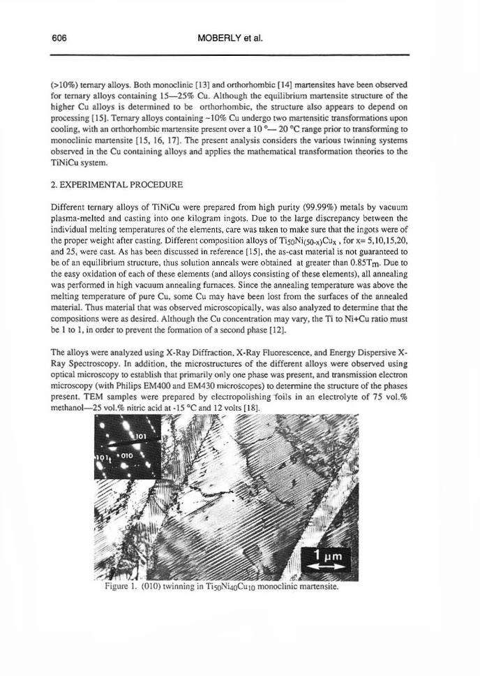
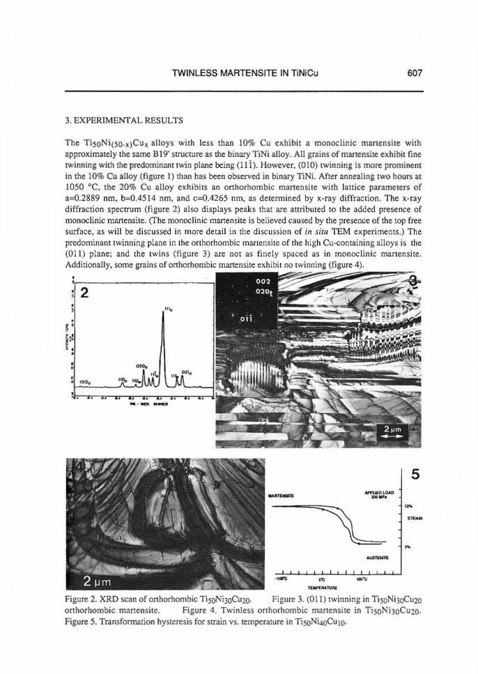
The TiSON i(SO_l)Cux alloys with less than 10% Cu exhibit a monoclinic manensi le with approximately the same 8 19' struclure as the binary TiNi alloy. All grains of martensite exhibit fine twinning with the predominant Iw'in plane being (1 1 i). However, (010) Iwinning is more prominenl in the 10% Cu alloy (figure I) than has been observed in binary TiNi. After annealing IWO hours at 1050 °e. the 20% eu alloy exhibi ts an orthorhombic martensite with lattice parameters of 3=0.2889 nm, b=O.45\4 nm, and c=0.4265 nm, as detennined by x-ray diffraction. The x-ray diffraction spectrum (figure 2) also displays peaks thaI are attributed to the added presence of monoclinic manensite. (The monoclinic marten site is believed caused by the presence of the top free surface, as will be discussed in more detail in the discussion of in rim TEM experiments.) The predominant twinning plane in the orthorhombic martensite of the high eu-containing alloys is the (011) plane; and the twins (figure 3) are not as finely spaced as in monoclin ic martensite. Additionally. some grains of orthorhombic martensite exhibil no twinning (figure 4).
2
5 ----
Figure 2. XRD scan of onhorhombic TisoNhoCu20. Figure 3. (011) twinning in TisoNi3()Cu20 orthorhombic m3nensile. Figure 4. Twinless orthorhombic martensite in TisON i)OCU20. Figure 5. Transformation hysleresis for strain "s. lem~ralUre in TisoNi4oCUIO.

608 MOBERLY et at
The 10% Cu alloy exhibits a 2-step transfonnation during strain (elongation) vs. temperature or resistivity vs. temperature tests. Figure 5 displays a plot of elongation due 10 an applied stress of 320 MPa as a 0.45 mm diameter wire is cooled and healed through the ttansformation Icmperarure. This 2-step transfonnation is still evidcnI aner subsequent thermal cycling. The inrennediale step is indicat ive of the presence of an intermediate manensite phase having an orthorhombic structure. In situ TEM heating and cooling experimenls were unable 10 observe the intermediate orthorhombic phase. as the B2 cubic austenite transfonntd directly to monoclinic martensite upon cooling.
Additional in situ TEM experiments were conducted to detennine if the orthorhombic martensite of the high (> 15%) Cu al loys would transform to a monoclinic martensite at low temperatures. The onhorhombic martensite remained stable upon cooling to liquid nitrogen (-186 oq temperature. After heating in situ to cause transfonnation to cubic austenite. however. the TEM thin foils would transfonn to monoclinic martensite with subsequent cooling. The lack of onhorhombic martensite after thennal cycling indicates the monoclinic struclUre to be preferred in a thin foil. This dependence of structure on macroscopic sample geometry and processing history indicates how both monoclinic and orthorhombic structures could have been observed by previous authors [13. 14]. and precludes using TEM alone to investigate the crystallographic orientation relationships between austenite and orthorhombic manensite.
4. DISCUSSIONS
A 2-dimensional projection can depict how the (001) orientations of both the onhorhombic and the monoclinic unit cell are derived from a (110) orientation of the cubic unit cell (figure 6). In the case of the monoclinic structure. a (010) twin plane may prevent large atom displacements during the transfonnation. Using the analysis of Knowles and Smith [8J for the monoclinic structure. the distortion matrices for the two twins are written with respect to cube directions [110]. [110] and [001]
[
cl.fiao TI'. 0
o
[
cl.fiao T2·. 0
o
b(siny)/..J2ao 0 o 0 1 b(cosy)l..fiao alao
o alao o
o 1 b(cosy)/...fiao b(siny)I..fiao
where. using the first monoclinic setting of Michal (51. the lattice parameters are
. a=0.2889 nm, b=O.4622 nm, c=O.4 12 nm, lhe angle between a and b axes: (-96.8°, and ao=O.3016 nm for the 8 2 cubic unit cell. From equation (8) of Wechsler (9J. the
:~at[i1" :~~ _~{:tilng the two twins is
o sin~ ClJir;.
D IOn)81 CUBIC
• • " • 0 0 • 112 .......
~-- - -OClt ~ [0011 1001) MONOCUNIC llRtrlORHOMBIC
• • • •
• • • •
(01 0lM TWin Plan.
Figure 6. Two-dimensional projection of orthorhombic and monoclinic (OOI)orientations derived from cubic (110), wilh (010) Iwinning.
TWIN LESS MARTENSITE IN liNiCu 609
Following the mathcmalica1 description of Liebennan's analysis (10) from equation (13) lhrough equation (41 ), the mathematical solutions for lhe twin fractions are 0.41 and 0.59, which agree with the relative twin fractions observed in figure I.
In the onhorhombic structure, however, the (010) plane is a plane of symmelI)' and is not a twin plane. lbe transfonnation of the cubic structure to the orthorhombic struCtw'e can follow diroclly the theory applied by Lieberman for AuCd {IO}. Using the lattice parameters listed above for the onhorhombic unit cell, the distortion matrix is written with respect to the onhorhombic axes as
[
b/.[2", 0 0 1 T,'. 0 cl..fiao 0
o 0 alao
The principal distortion ctJ2ao :::0.99993, is almost unity, and allows for a homogeneous distortion. This implies the distonion of the martensitic InUlsfonnation rna)' be accounted for without twinning [10). which is the case observed in figure 4. (The slight discrepancy between the distortion and unity may be accounted for by dislocation slip during transfonnation and/or occasional twinning that was not observed by el~tron microscopy.)
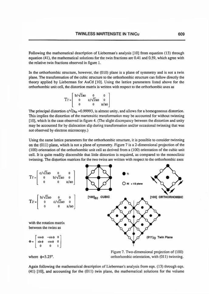
Using the same lattice parameters for the onhorhombic structure, it is possible to consider twinning on the (011) plane. which is not a plane of symmeny. Figure 7 is a 2-dimensional projection of the (100) orientation of the orthorhombic unit cell as derived from a (100) orienlation of the cubic unit cell, It is quite readily discernible mat little distortion is required, as compared to the monoclinic twinning. The diS.lonion mattices for me two twins are wrinen with respect to the orthorhombic axes
[
,/.[2. . 0 0 1 TI' . 0 b/..fiao 0
o 0 alao
[
b/.[2ao 0 0 1 T 2'. 0 cl..fiao 0
o 0 a/ao
with the rotation matrix. between me twins as
[ - . -.m, 0: 1 ~ . lint ~t
o 0
,0' "'Q ,
'U" ,
",0
[100IB2 CUBIC
e n
[100) ORTHORHOMBIC
(011 )0 Twin Plane
Figure 7. Two-dimensional projection of (100) orthorhombic orientation, with (0 11 ) twinning.
Again following the mathematical description of Lieberman's analysis from eqn. (13) through eqn. (41) [10], and accounting for the (011) twin plane, the mathematical solutions for the vol ume
610 MOBERLY et al.
fraction of tile twins are 0.999 and 0.001. These values are approximately unity and zero, seeming [0
imply thaI a twinless transformation should OCCUI. However, such mathematical solutions also imply that it does not maner which twin forms or which distortion occurs. This solution could account for random twinning. as is actually observed in figure 3. Since the distortions are minimal, the twins do not need to be fine . The twinned structure observed in figure 3 is more a result of nuclealion variations rather than as a necessity to satisfy twin volume fractions of the transfonnation theory. Twins. once nucleated. tend 10 traverse the entire grain. As would be expected for random twinning. the overall volume fraction of each twin in an individual grain is - 0.5.
4. CONCLUSIONS
1) When large concentrations of eu (up to 30%) are substituted for Ni in TiNi alloys, the shape memory propenies are modified, most importantly by the narrowing of the temperature range of the transfonnation hysteresis.
2) Ternary TiNiCu alloys with greater than 10% Cu exhibit an orthorhombic manensite. Although many orthorhombic grains exhibit (011) [Winning, some grains exhibit a twinless rnanensile.
3) The twinned (and [Winless) orthorhombic manensite, as weU as !he twinned monoclinic manensite in the 10% Cu alloy, correspond with the ma!hematical solutions based on transfonnation theories of Lieberman, Wechsler, and Read (10).
4) The 10% Cu ternary alloy exhibits a two-step transfonnation upon cooling from B2 austenite to orthorhombic manensite to monoclinic martensite. which in [Urn provides this alloy with a two· Step reversible shape change.
REFERENCES I. Purdy.G.R. and Parr. J.G.:Trans. AIME. 1961. llL 631. 2. Wayman.C.M.: Shape MemQry Effecls ConL Proc. China. 1986.p.59. 3. Otsuka.K . and Shimizu, K.: Intern!. Met. Rev .• 1986 • .li, 93. 4. Kudoh,Y .• Tokonami.M .• Miyazaki. S. and Otsuka, K. : Acta Metall., 1985. n. 2049. 5. Michal. G.M. and Sinclair. R.: Acta Crystal., 1981.JU1, 1803. 6. Gupta,S.P. and Johnson. A.A.: Trans. TIM , 1973, li, 292. 7. Sinclair,R.: AlP Conf. Proc.,1979. il. 269. 8. Knowles,K.M. and Smith. D.A.: Acta Metall.. 1981.ll. 101. 9. Wechsler,M.S., Liebennan. D.S . and Read, T.A.: Trans. AlME,1953. 12, 1503. 10. Liebennan, D.S .• Wechsler,M.S. and Read, T.A.: J. AppJ. Phys .• 1955. ~, 473. II . Mercier. O. and Meleon. K.N.: Met. Trans., 1979 • .lOa. 387. 12. Alisova. S.P .• Volynskaya,N.V., Budberg, P.B. and Kobylkin. A.N.: Izvestiya Akademii
Nauk. SSSR. Melally. 1986, i. 210. 13. Bricknell, R.H .• Melton. K.N. and Mercier, 0. : Met. Trans .• 1979 • .lllA. 693. 14. Tadaki, T. and Wayman. C.M.: Metallography. 1982.l5.. 233. 15. Moberly. WJ. and Melton. K.N.: Engineering Aspects ofSbape Memory Alloys.
(r.W,Duerig and C.M.Wayman, ed.), (Butterwonhs Publishers, London). (in press). 16. Yerofeyev.V.Y .• Monasevich.L.A.,Pavskaya.V.A. and Paskal ,Y.I.:Phys. Met .• 1982. ~.86 . 17. Tokarev. V.N .• Savvinov. A.S. and Khachin. V.N.: Phys. Met. Metall.. 1983 • .i!i:, 117. 18. Michal.G.M. :DjffusiQnless Transformations in TiNi. Thesis.Stanford University (1979).