mobile broadband wireless antennas - farnell element14 · mobile antennas low profile whipless...
TRANSCRIPT

Rugged SolutionS foR Mobile ApplicAtionSn Permanent,TemporaryandCovertInstallations
n WidebandandMulti-bandTechnologies
n Voice,VideoandDataSupport
n Supporting700MHzLTE,800/900MHz,3G,4G, Wi-FiandWiMAXBroadbandWirelessNetworks
n Attractive,lowprofiledesigns
n GPSSupportcapabilityalsoavailable
Mobile bRoAdbAnd wiReleSS AntennAS
www.antenna.com
1 PCTEL, Inc. WEB: www.antenna.pctel.comPCTEL, Inc. WEB: www.antenna.com
MOBILE ANTENNASMolded Base Antennas
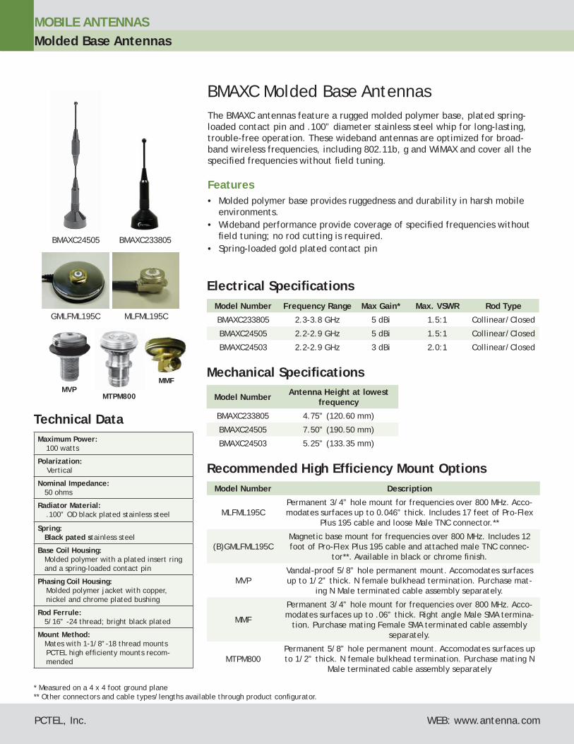
BMAXC Molded Base AntennasThe BMAXC antennas feature a rugged molded polymer base, plated spring-loaded contact pin and .100” diameter stainless steel whip for long-lasting, trouble-free operation. These wideband antennas are optimized for broad-band wireless frequencies, including 802.11b, g and WiMAX and cover all the specifi ed frequencies without fi eld tuning.
Features• Molded polymer base provides ruggedness and durability in harsh mobile
environments. • Wideband performance provide coverage of specifi ed frequencies without
fi eld tuning; no rod cutting is required. • Spring-loaded gold plated contact pin
Technical Data Maximum Power:
100 watts
Polarization: Vertical
Nominal Impedance: 50 ohms
Radiator Material:.100” OD black plated stainless steel
Spring: Black pated stainless steel
Base Coil Housing: Molded polymer with a plated insert ring and a spring-loaded contact pin
Phasing Coil Housing:Molded polymer jacket with copper, nickel and chrome plated bushing
Rod Ferrule: 5/16” -24 thread; bright black plated
Mount Method: Mates with 1-1/8”-18 thread mounts
PCTEL high effi cienty mounts recom-mended
Mechanical Specifi cations
Model Number Antenna Height at lowest frequency
BMAXC233805 4.75” (120.60 mm)
BMAXC24505 7.50” (190.50 mm)
BMAXC24503 5.25” (133.35 mm)
Model Number Frequency Range Max Gain* Max. VSWR Rod Type
BMAXC233805 2.3-3.8 GHz 5 dBi 1.5:1 Collinear/Closed
BMAXC24505 2.2-2.9 GHz 5 dBi 1.5:1 Collinear/Closed
BMAXC24503 2.2-2.9 GHz 3 dBi 2.0:1 Collinear/Closed
Electrical Specifi cations
* Measured on a 4 x 4 foot ground plane** Other connectors and cable types/lengths available through product confi gurator.
Recommended High Effi ciency Mount OptionsModel Number Description
MLFML195CPermanent 3/4” hole mount for frequencies over 800 MHz. Acco-modates surfaces up to 0.046” thick. Includes 17 feet of Pro-Flex
Plus 195 cable and loose Male TNC connector.**
(B)GMLFML195CMagnetic base mount for frequencies over 800 MHz. Includes 12 foot of Pro-Flex Plus 195 cable and attached male TNC connec-
tor**. Available in black or chrome fi nish.
MVPVandal-proof 5/8” hole permanent mount. Accomodates surfaces up to 1/2” thick. N female bulkhead termination. Purchase mat-
ing N Male terminated cable assembly separately.
MMF
Permanent 3/4” hole mount for frequencies over 800 MHz. Acco-modates surfaces up to .06” thick. Right angle Male SMA termina-
tion. Purchase mating Female SMA terminated cable assembly separately.
MTPM800Permanent 5/8” hole permanent mount. Accomodates surfaces up to 1/2” thick. N female bulkhead termination. Purchase mating N
Male terminated cable assembly separately
MMF
MLFML195CGMLFML195C
MTPM800MVP
BMAXC24505 BMAXC233805
Technical Data Maximum Power:
50 watts (MEFC24005 only) 10 watts (all other models)
Polarization:Vertical
Nominal Impedance:50 Ohm
VSWR:<1.5:1
Return Loss:< 10 dB
Radome Material:UV stable ABS
Radiator Material:.100” OD stainless steel; bright (MEFC) or black finish (BMEFC)
Mount Method:Compatible with most 1-1/8”-18 thread mounts. See recommended mount op-tions for each model.*
MOBILE ANTENNASElevated Feed Point Antennas
* Models (B)MEFC49005HF and (B)MEFC58005HF must be ordered with recom-mended mount(s) listed above. Consult factory for other connector options of-fered with these mounts.
Mounting Options
Antenna Model Recommended Mount Model(s) Options
(B)MEFC24005 MLFML195CLow frequency 3/4” hole permanent mount, 17 ft. Pro-FlexTM Plus 195, TNC male standard
(B)MEFC24005 GMLFML195C Low frequency magnetic mount, 12 ft. Pro-FlexTM Plus 195, TNC male standard
(B)MEFC24005 MVP Permanent Mount, 5/8” hole; 1-1/8”-18 thread; thick plate mount
(B)MEFC49005HF(B)MEFC58005HFMEFC2427HF
MHFML195C* Permanent Mount, 17 ft. Pro-FlexTM Plus 195, TNC male loose
(B)MEFC49005HF(B)MEFC58005HF MEFC2427HF
GMHFML195C* Magnetic Mount, 12 ft. Pro-FlexTM Plus 195, TNC male attached
(B)MEFC49005HF(B)MEFC58005HFMEFC2427HF
MVPHF Permanent Mount, 5/8” hole; 1-1/8”-18 thread; thick plate mount
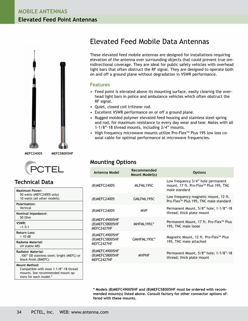
Elevated Feed Mobile Data Antennas
These elevated feed mobile antennas are designed for installations requiring elevation of the antenna over surrounding objects that could prevent true om-nidirectional coverage. They are ideal for public safety vehicles with overhead light bars that often obstruct the RF signal. They are designed to operate both on and off a ground plane without degradation in VSWR performance.
Features• Feed point is elevated above its mounting surface, easily clearing the over-
head light bars in police and ambulance vehicles which often obstruct the RF signal.
• Quiet, closed coil trilinear rod.• Excellent VSWR performance on or off a ground plane.• Rugged molded polymer elevated feed housing and stainless steel spring
and rod, for maximum resistance to every day wear and tear. Mates with all 1-1/8”-18 thread mounts, including 3/4” mounts.
• High frequency microwave mounts utilize Pro-FlexTM Plus 195 low loss co-axial cable for optimal performance at microwave frequencies.
34 PCTEL, Inc. WEB: www.antenna.com
MEFC24005 MEFC58005HF
MOBILE ANTENNASElevated Feed Point Antennas
PCTEL, Inc. WEB: www.antenna.com 35
Antenna Electrical Specifications
Model Frequency Range Gain(ground Plane)
Gain (no Ground Plane)
Horizontal Beamwidth@1/2 Power
Vertical Beamwidth@1/2 Power
(B)MEFC24005* 2.4-2.5 GHz 5 dBi 3.5 dBi 360° 45°
(B)MEFC49005HF 4.9-5.0 GHz 5.5 dBi 5.5 dBi 360° 18°
(B)MEFC58005HF 5.7-5.8 GHz 5.5 dBi 5.5 dBi 360° 18°
MEFC2427HF 2.4-2.7 GHz 5 dBi 5 dBi 360° 26°
Mechanical Specifications
Model Antenna Height
Weight(Mass)
Temperature Range
Wind Loading (Frontal) @ 125mph
Bending Moment @ 125 mph
(B)MEFC24005* 16” (40.6 cm) 0.5 lbs (0.227 kg) -40°C to +70°C 3.1 lbf. 18.6 in-lb
(B)MEFC49005HF 12” (30.4 cm) 0.5 lbs (0.227 kg) -40°C to +70°C 3.1 lbf. 18.6 in-lb
(B)MEFC58005HF 12” (30.4 cm) 0.5 lbs (0.227 kg) -40°C to +70°C 3.1 lbf. 18.6 in-lb
MEFC2427HF 13.6” (34.54 cm)
0.5 lbs (0.227 kg) -40°C to +70°C 3.1 lbf. 18.6 in-lb
*Prefix “B” indicates all black finish.
MOBILE ANTENNASLow Profile Whipless Antennas
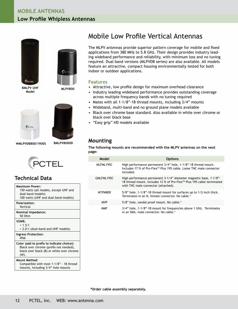
Mobile Low Profile Vertical AntennasThe MLPV antennas provide superior pattern coverage for mobile and fixed applications from 380 MHz to 5.8 GHz. Their design provides industry lead-ing wideband performance and reliability, with minimum loss and no tuning required. Dual band versions (MLPVDB series) are also available. All models feature an attractive, compact housing environmentally tested for both indoor or outdoor applications.
Features• Attractive, low profile design for maximum overhead clearance• Industry leading wideband performance provides outstanding coverage
across multiple frequency bands with no tuning required• Mates with all 1-1/8”-18 thread mounts, including 3/4” mounts• Wideband, multi-band and no ground plane models available • Black over chrome base standard. Also available in white over chrome or
black over black base• “Easy grip” HD models available
Technical Data Maximum Power:
150 watts (all models, except UHF and dual band models)100 watts (UHF and dual band models)
Polarization:Vertical
Nominal Impedance:50 Ohm
VSWR:< 1.5:1< 2.0:1 (dual-band and UHF models)
Ingress Protection:IP66
Color (add to prefix to indicate choice):Black over chrome (prefix not needed), black over black (B) or white over chrome (W).
Mount Method:Compatible with most 1-1/8” - 18 thread mounts, including 3/4” hole mounts
MountingThe following mounts are recommended with the MLPV antennas on the next page:
Model Options
MLFML195C High performance permanent 3/4” hole, 1-1/8”-18 thread mount. Includes 17 ft of Pro-FlexTM Plus 195 cable. Loose TNC male connector included.
GMLFML195C High performance permanent 3-1/4” diameter magnetic base, 1-1/8”-18 thread mount. Includes 12 ft of Pro-FlexTM Plus 195 cable terminated with TNC male connector (attached).
MTPM800 5/8” hole, 1-1/8”-18 thread mount for surfaces up to 1/2-inch thick. Terminates in an N, female connector. No cable.*
MVP 5/8” hole, vandal proof mount. No cable.*
MMF 3/4” hole, 1-1/8”-18 mount for frequencies above 1 GHz. Terminates in an SMA, male connector. No cable.*
*Order cable assembly separately.
BMLPV UHF Model
WMLPVDB800/1900S
MLPV800
BMLPV800HD
12 PCTEL, Inc. WEB: www.antenna.com

MOBILE ANTENNASLow Profile Whipless Antennas
Antenna Electrical Specifications Model* Frequency Range Bandwidth Gain***
MLPV380 380-410 MHz 30 MHz Unity
MLPV406 406-440 MHz 34 MHz Unity
MLPV430 430-480 MHz 50 MHz Unity
MLPV450 450-512 MHz 62 MHz Unity
MLPV698 698-806 MHz 108 MHz Unity
MLPV700 740-870 MHz 130 MHz 3 dBi***
MLPV800 806-960 MHz 154 MHz 3 dBi***
BMLPV800HD 806-960 MHz 154 MHz 3 dBi***
BMLPVDB700/2500 698-960 MHz and 1710-2500 MHz 262 MHz and 790 MHz 3 dBi/4 dBi
MLPVDB800/1900 806-960 MHz and 1710-1990 MHz 154 MHz and 280 MHz 3 dBi/4 dBi
BMLPVDB800/1900HD 806-960 MHz and 1710-1990 MHz 154 MHz and 280 MHz 3 dBi/4 dBi
MLPVDB800/1900S 806-960 MHz and 1710-2500 MHz 154 MHz and 790 MHz 3 dBi/4 dBi
MLPVDB902/2400 902-928 MHz and 2400-2500 MHz 26 MHz and 100 MHz 3 dBi/4 dBi
MLPVDB902/2400S 902-928 MHz and 2400-2500 MHz 26 MHz and 100 MHz 3 dBi/4 dBi
MLPV1700 1700-2700 MHz 1000 MHz 4 dBi***
MLPVDB2458 2.4-2.5 GHz and 4.9-5.9 GHz 100 MHz / 1000 MHz 3 dBi/4 dBi
MLPV4900 4.9-5.9 GHz 1000 MHz 4 dBi
Mechanical SpecificationsModel (all colors)* Antenna Dimensions Weight (Mass) Temperature Range
MLPV380 3.38” H x 1.5” OD 0.31 lbs (.14 kg) -40º C to 70º C
MLPV406 3.38” H X 1.5” OD 0.31 lbs (.14 kg) -40º C to 70º C
MLPV430 3.38” H X 1.5” OD 0.31 lbs (.14 kg) -40º C to 70º C
MLPV450 3.38” H X 1.5” OD 0.31 lbs (.14 kg) -40º C to 70º C
MLPV698 3.38” H X 1.5” OD 0.31 lbs (.14 kg) -40º C to 70º C
MLPV700 2.4” H X 1.5” OD 0.29 lbs (0.13 kg) -40º C to 70º C
MLPV800 2.4” H X 1.5” OD 0.29 lbs (0.13 kg) -40º C to 70º C
BMLPV800HD 2.4” H x 1.5” W x 1.7” D (at the base) 0.44 lbs (0.19 kg) -40º C to 70º C
BMLPVDB700/2500 2.4” H x 1.5” OD 0.29 lbs (0.13 kg) -40º C to 70º C
MLPVDB800/1900 2.4” H X 1.5” OD 0.29 lbs (0.13 kg) -40º C to 70º C
BMLPV800/1900HD 2.4” H x 1.5” W x 1.7” D (at the base) 0.44 lbs (0.19 kg) -40º C to 70º C
MLPVDB800/1900S 1.79” H x 1.5” OD 0.29 lbs (0.13 kg) -40º C to 70º C
MLPVDB902/2400 2.4” H X 1.5” OD 0.29 lbs (0.13 kg) -40º C to 70º C
MLPVDB902/2400S 1.79” H x 1.5” OD 0.29 lbs (0.13 kg) -40º C to 70º C
MLPV1700 1.79” H x 1.5” OD 0.34 lbs (0.15 kg) -40º C to 70º C
MLPVDB2458 1.79” H x 1.5” OD (at the base) 0.34 lbs (0.15 kg) -40º C to 70º C
MLPV4900** 1.79” H x 1.5” OD (at the base) 0.34 lbs (0.15 kg) -40º C to 70º C
* To order black over black version, add the prefix “B” to the part number. To order the white over chrome version, add the pre-fix “W” to the part number. Not all models are available in black or white. Call Customer Service for availability.*** Measured on a 4 foot diameter ground plane. Gain is ground plane dependent.
PCTEL, Inc. WEB: www.antenna.com 13
MOBILE ANTENNASLow Profile Whipless Antennas
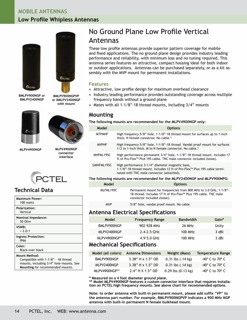
No Ground Plane Low Profile Vertical AntennasThese low profile antennas provide superior pattern coverage for mobile and fixed applications. The no ground plane design provides industry leading performance and reliability, with minimum loss and no tuning required. This antenna series features an attractive, compact housing ideal for both indoor or outdoor applications. Antennas can be purchased separately, or as a kit as-sembly with the MVP mount for permanent installations.
Features• Attractive, low profile design for maximum overhead clearance• Industry leading performance provides outstanding coverage across multiple
frequency bands without a ground plane• Mates with all 1-1/8”-18 thread mounts, including 3/4” mounts
Antenna Electrical Specifications Model Frequency Range Bandwidth Gain*
BMLPV900NGP 902-928 MHz 26 MHz Unity
MLPV2400NGP 2.4-2.5 GHz 100 MHz 3 dBi
MLPV4900NGP** 4.9-5.0 GHz 100 MHz 3 dBi
Mechanical SpecificationsModel (all colors) Antenna Dimensions Weight (Mass) Temperature Range
BMLPV900NGP 3.38” H x 1.5” OD 0.31 lbs (.14 kg) -40º C to 70º C
MLPV2400NGP 3.38” H x 1.5” OD 0.31 lbs (.14 kg) -40º C to 70º C
MLPV4900NGP** 2.4” H X 1.5” OD 0.29 lbs (0.13 kg) -40º C to 70º C
* Measured on a 4 foot diameter ground plane.** Model MLPV4900NGP features a custom connector interface that requires installa-tion on PCTEL high frequency mounts. See above chart for recommended options.
Note: to order antenna with built-in permanent mount, please add suffix “VP” to the antenna part number. For example, BMLPV900NGPVP indicates a 900 MHz NGP antenna with built-in permanent N female bulkhead mount.
Technical Data Maximum Power:
100 watts
Polarization:Vertical
Nominal Impedance:50 Ohm
VSWR:< 2.0:1
Ingress Protection:IP66
Color:Black over black
Mount Method:Compatible with 1-1/8” - 18 thread mounts, including 3/4” hole mounts. See Mounting for recommended mounts.
BMLPV900NGP or BMLPV2400NGP
BMLPV900NGPVP or BMLPV2400NGP
with mount
MLPV4900NGP connector interface
MLPV4900NGP
14 PCTEL, Inc. WEB: www.antenna.com
Model Options
MTPMHF High frequency 5/8” hole, 1-1/8”-18 thread mount for surfaces up to 1-inch thick. N female connector. No cable.*
MVPHF High frequency 5/8” hole, 1-1/8”-18 thread. Vandal proof mount for surfaces 1/2 to 1-inch thick. M to N female connector. No cable.*
MHFML195C High performance permanent 3/4” hole, 1-1/8”-18 thread mount. Includes 17 ft of Pro-FlexTM Plus 195 cable. TNC male connector included (loose).
GMHFML195C High performance 3-1/4” diameter magnetic base, 1-1/8”-18 thread mount. Includes 12 ft of Pro-FlexTM Plus 195 cable termi-nated with TNC male connector (attached).
Mounting The following mounts are recommended for the MLPV4900NGP only:
Model Options
MLFML195C Permanent mount for frequencies from 800 MHz to 3.0 GHz, 1-1/8”-18 thread. Includes 17 ft of Pro-FlexTM Plus 195 cable. TNC male connector included (loose).
MVP 5/8” hole, vandal proof mount. No cable.
The following mounts are recommended for the MLPV2400NGP and MLPV900NPG:
MOBILE ANTENNASElevated Feed Point Antennas
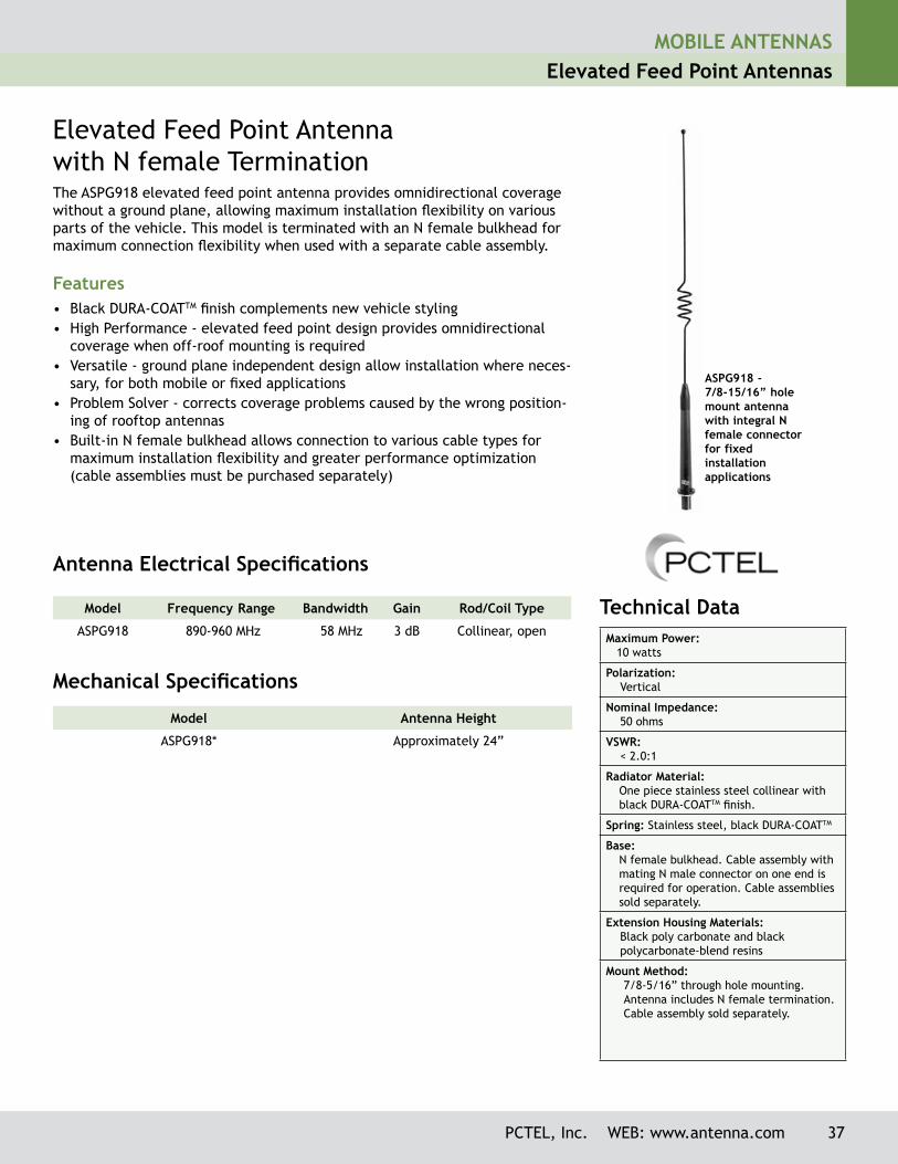
ASPG918 -7/8-15/16” hole mount antenna with integral N female connectorfor fixed installation applications
Technical Data Maximum Power: 10 watts
Polarization: Vertical
Nominal Impedance: 50 ohms
VSWR: < 2.0:1
Radiator Material:One piece stainless steel collinear with black DURA-COATTM finish.
Spring: Stainless steel, black DURA-COATTM
Base: N female bulkhead. Cable assembly with mating N male connector on one end is required for operation. Cable assemblies sold separately.
Extension Housing Materials: Black poly carbonate and black polycarbonate-blend resins
Mount Method: 7/8-5/16” through hole mounting.
Antenna includes N female termination. Cable assembly sold separately.
Elevated Feed Point Antenna with N female TerminationThe ASPG918 elevated feed point antenna provides omnidirectional coverage without a ground plane, allowing maximum installation flexibility on various parts of the vehicle. This model is terminated with an N female bulkhead for maximum connection flexibility when used with a separate cable assembly.
Features• Black DURA-COATTM finish complements new vehicle styling• High Performance - elevated feed point design provides omnidirectional
coverage when off-roof mounting is required• Versatile - ground plane independent design allow installation where neces-
sary, for both mobile or fixed applications• Problem Solver - corrects coverage problems caused by the wrong position-
ing of rooftop antennas • Built-in N female bulkhead allows connection to various cable types for
maximum installation flexibility and greater performance optimization (cable assemblies must be purchased separately)
Model Frequency Range Bandwidth Gain Rod/Coil Type
ASPG918 890-960 MHz 58 MHz 3 dB Collinear, open
Antenna Electrical Specifications
Mechanical Specifications
Model Antenna Height
ASPG918* Approximately 24”
PCTEL, Inc. WEB: www.antenna.com 37
32 PCTEL, Inc. WEB: www.antenna.com
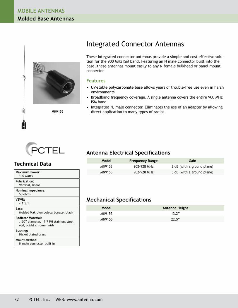
Integrated Connector Antennas
Model Frequency Range Gain
MN9153 902-928 MHz 3 dB (with a ground plane)
MN9155 902-928 MHz 5 dB (with a ground plane)
Antenna Electrical Specifications
Mechanical SpecificationsModel Antenna Height
MN9153 13.2”
MN9155 22.5”
These integrated connector antennas provide a simple and cost effective solu-tion for the 900 MHz ISM band. Featuring an N male connector built into the base, these antennas mount easily to any N female bulkhead or panel mount connector.
Features• UV-stable polycarbonate base allows years of trouble-free use even in harsh
environments• Broadband frequency coverage. A single antenna covers the entire 900 MHz
ISM band• Integrated N, male connector. Eliminates the use of an adapter by allowing
direct application to many types of radios
Technical Data Maximum Power:
100 watts
Polarization:Vertical, linear
Nominal Impedance:50 ohms
VSWR:< 1.5:1
Base:Molded Makrolon polycarbonate; black
Radiator Material:.100” diameter, 17-7 PH stainless steel rod; bright chrome finish
Bushing:Nickel plated brass
Mount Method:N male connector built in
MN9155
MOBILE ANTENNASMolded Base Antennas
MOBILE ANTENNASPermanent Mounts
PCTEL, Inc. WEB: www.antenna.com 77
* Cable assembly with mating connector sold separately.** High frequency mount to be used with (B)MEFC49005HF, (B)MEFC58005HF, MEFC2327HF and MLPV4900NGP
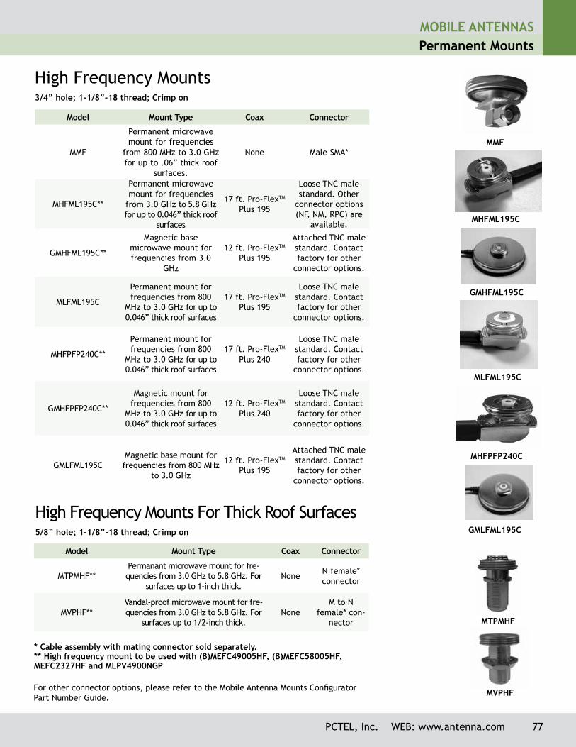
High Frequency Mounts3/4” hole; 1-1/8”-18 thread; Crimp on
Model Mount Type Coax Connector
MMF
Permanent microwave mount for frequencies
from 800 MHz to 3.0 GHz for up to .06” thick roof
surfaces.
None Male SMA*
MHFML195C**
Permanent microwave mount for frequencies
from 3.0 GHz to 5.8 GHz for up to 0.046” thick roof
surfaces
17 ft. Pro-FlexTM Plus 195
Loose TNC male standard. Other
connector options (NF, NM, RPC) are
available.
GMHFML195C**
Magnetic base microwave mount for frequencies from 3.0
GHz
12 ft. Pro-FlexTM Plus 195
Attached TNC male standard. Contact factory for other
connector options.
MLFML195C
Permanent mount for frequencies from 800
MHz to 3.0 GHz for up to 0.046” thick roof surfaces
17 ft. Pro-FlexTM Plus 195
Loose TNC male standard. Contact factory for other
connector options.
MHFPFP240C**
Permanent mount for frequencies from 800
MHz to 3.0 GHz for up to 0.046” thick roof surfaces
17 ft. Pro-FlexTM Plus 240
Loose TNC male standard. Contact factory for other
connector options.
GMHFPFP240C**
Magnetic mount for frequencies from 800
MHz to 3.0 GHz for up to 0.046” thick roof surfaces
12 ft. Pro-FlexTM Plus 240
Loose TNC male standard. Contact factory for other
connector options.
GMLFML195CMagnetic base mount for frequencies from 800 MHz
to 3.0 GHz
12 ft. Pro-FlexTM Plus 195
Attached TNC male standard. Contact factory for other
connector options.
High Frequency Mounts For Thick Roof Surfaces5/8” hole; 1-1/8”-18 thread; Crimp on
Model Mount Type Coax Connector
MTPMHF**Permanant microwave mount for fre-quencies from 3.0 GHz to 5.8 GHz. For
surfaces up to 1-inch thick.None N female*
connector
MVPHF**Vandal-proof microwave mount for fre-quencies from 3.0 GHz to 5.8 GHz. For
surfaces up to 1/2-inch thick.None
M to N female* con-
nector
MMF
MHFML195C
MLFML195C
GMLFML195C
GMHFML195C
MVPHF
MHFPFP240C
MTPMHF
For other connector options, please refer to the Mobile Antenna Mounts Configurator Part Number Guide.
MOBILE ANTENNASMagnetic Mount Base Antennas
Model Frequency Range Gain
BMMG824/1900ML195* 824-896 MHz/1850-1990 MHz 2 dBi/6 dBi
BMMG24005ML195* 2400-2484 MHz 5 dBi
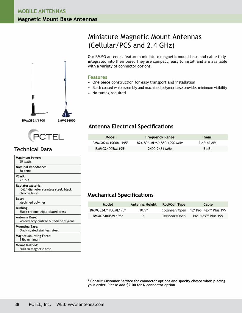
Miniature Magnetic Mount Antennas (Cellular/PCS and 2.4 GHz)Our BMMG antennas feature a miniature magnetic mount base and cable fully integrated into their base. They are compact, easy to install and are available with a variety of connector options.
Features• One piece construction for easy transport and installation• Black coated whip assembly and machined polymer base provides minimum visibility• No tuning required
Antenna Electrical Specifications
Mechanical Specifications
Model Antenna Height Rod/Coil Type Cable
BMMG824/1900ML195* 10.5” Collinear/Open 12’ Pro-FlexTM Plus 195
BMMG24005ML195* 9” Trilinear/Open Pro-FlexTM Plus 195
Technical Data Maximum Power:
50 watts
Nominal Impedance:50 ohms
VSWR:< 1.5:1
Radiator Material:.062” diameter stainless steel, black chrome finish
Base:Machined polymer
Bushing:Black chrome triple-plated brass
Antenna Base:Molded acrylonitrile butadiene styrene
Mounting Base:Black coated stainless steel
Magnet Mounting Force:5 lbs minimum
Mount Method:Built-in magnetic base
BMMG824/1900 BMMG24005
* Consult Customer Service for connector options and specify choice when placing your order. Please add $2.00 for N connector option.
38 PCTEL, Inc. WEB: www.antenna.com
MOBILE ANTENNASCovert Antennas
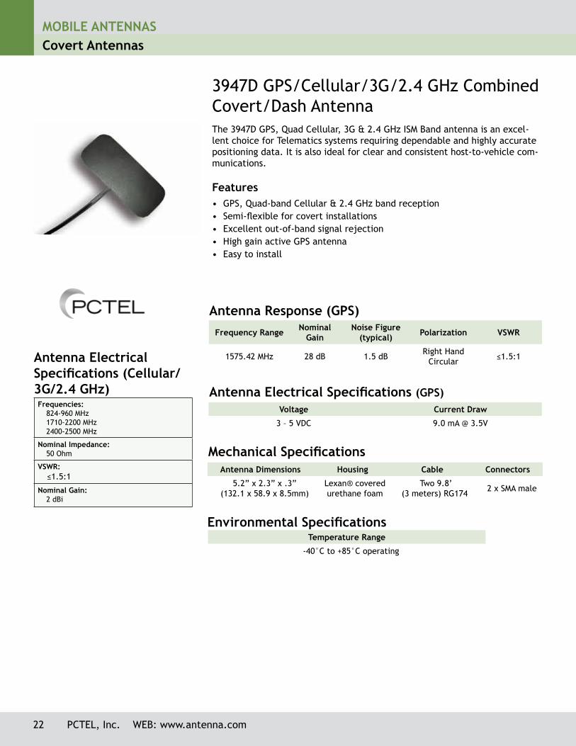
3947D GPS/Cellular/3G/2.4 GHz Combined Covert/Dash AntennaThe 3947D GPS, Quad Cellular, 3G & 2.4 GHz ISM Band antenna is an excel-lent choice for Telematics systems requiring dependable and highly accurate positioning data. It is also ideal for clear and consistent host-to-vehicle com-munications.
Features• GPS, Quad-band Cellular & 2.4 GHz band reception• Semi-flexible for covert installations• Excellent out-of-band signal rejection• High gain active GPS antenna• Easy to install
Antenna Electrical Specifications (GPS)
Antenna Dimensions Housing Cable Connectors
5.2” x 2.3” x .3” (132.1 x 58.9 x 8.5mm)
Lexan® covered urethane foam
Two 9.8’ (3 meters) RG174 2 x SMA male
Mechanical Specifications
Environmental Specifications Temperature Range
-40°C to +85°C operating
Voltage Current Draw
3 – 5 VDC 9.0 mA @ 3.5V
Frequency Range NominalGain
Noise Figure (typical) Polarization VSWR
1575.42 MHz 28 dB 1.5 dB Right Hand Circular ≤1.5:1
Antenna Response (GPS)
Antenna Electrical Specifications (Cellular/ 3G/2.4 GHz)Frequencies:
824-960 MHz1710-2200 MHz 2400-2500 MHz
Nominal Impedance:50 Ohm
VSWR: ≤1.5:1
Nominal Gain:2 dBi
22 PCTEL, Inc. WEB: www.antenna.com

MOBILE ANTENNASCovert Antennas
18 PCTEL, Inc. WEB: www.antenna.com
APDM5920U, vertical installation. The antenna can also be
installed horizontally.
Technical Data Maximum Power:
10 watts
Polarization:Linear, horizontal or vertical
Nominal Impedance:50 ohms
VSWR:< 2.0:1
Radiator Material:ABS
Coax Cable: 10 ft RG-174/U cable (bottom fed)
ConnectorSAP (female FME)
Mounting Method:Normount® Z500 tape
Inside Window Glass Mount
This vertical or horizontal polarization antenna is designed for inside glass mount installations operating in the 800 MHz cellular, 900 MHz trunking, 1800 MHz DCS and 1900 MHz PCS bands without the need for tuning. Its tape mount easily attaches to a vehicle’s windshield or other glass surfaces making the antenna ideal for public safety or other applications requiring an unobtrusive design.
Features• Quad Band — covers 800 MHz cellular, 900 MHz trunking, 1800 MHz DCS, and
1900 MHz PCS• Low Profile — “sleek” appearance blends well with car dash interior• Efficient — simple mounting method allows installation in minutes without
holes• Economical — one antenna serves the function of four, minimizing installa-
tion and inventory requirements• Antenna can be oriented vertically or horizontally for maximum installation
flexibility
Antenna Electrical Specifications Model Frequency Range Gain Bandwidth
APDM5920U 824-960/1710-1990 MHz Unity 136/280 MHz
Normount® is a registered trademark of Norton, a Saint-Gobain Co.
Mechanical SpecificationsModel Antenna Dimensions
APDM5920U 0.5” D x 5.9” L
MOBILE ANTENNASCovert Antennas
PCTEL, Inc. WEB: www.antenna.com 19
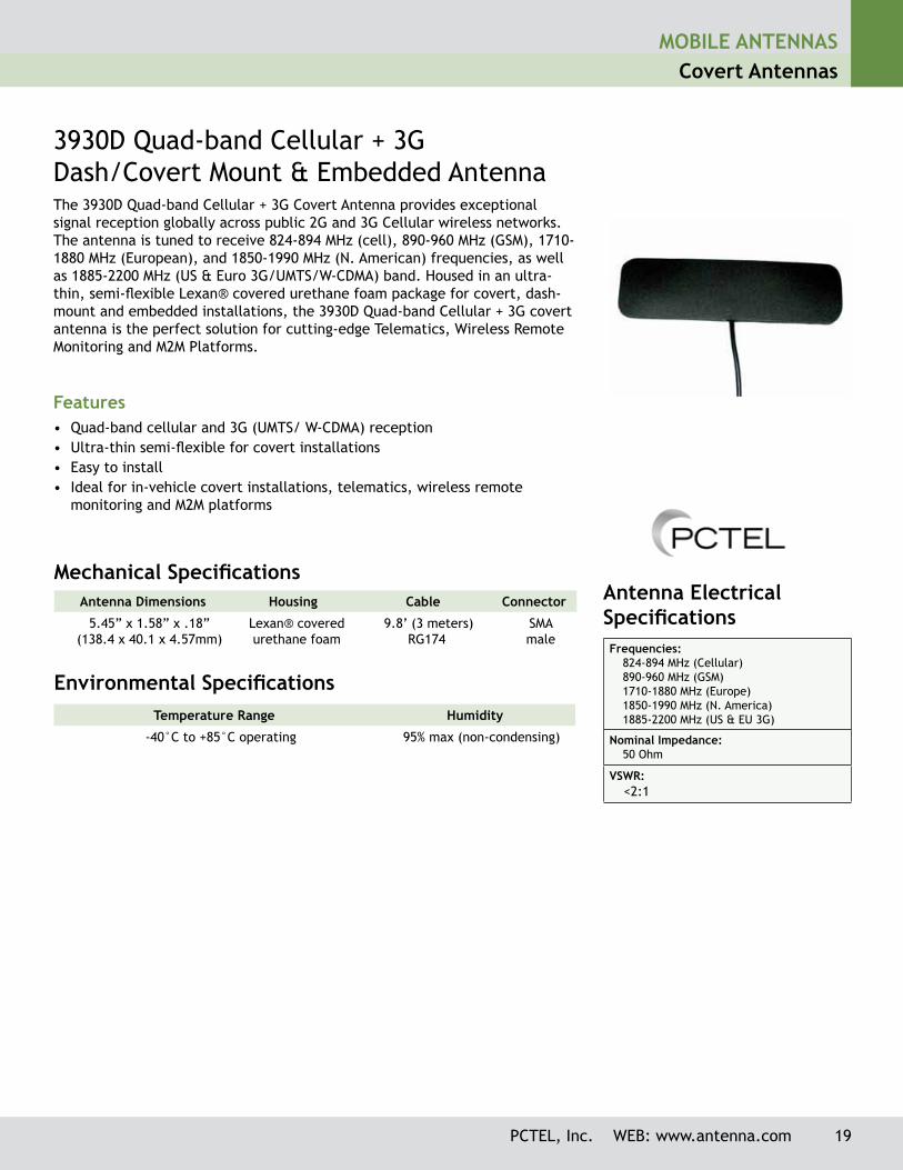
3930D Quad-band Cellular + 3GDash/Covert Mount & Embedded AntennaThe 3930D Quad-band Cellular + 3G Covert Antenna provides exceptional signal reception globally across public 2G and 3G Cellular wireless networks. The antenna is tuned to receive 824-894 MHz (cell), 890-960 MHz (GSM), 1710-1880 MHz (European), and 1850-1990 MHz (N. American) frequencies, as well as 1885-2200 MHz (US & Euro 3G/UMTS/W-CDMA) band. Housed in an ultra-thin, semi-flexible Lexan® covered urethane foam package for covert, dash-mount and embedded installations, the 3930D Quad-band Cellular + 3G covert antenna is the perfect solution for cutting-edge Telematics, Wireless Remote Monitoring and M2M Platforms.
Features• Quad-band cellular and 3G (UMTS/ W-CDMA) reception• Ultra-thin semi-flexible for covert installations• Easy to install• Ideal for in-vehicle covert installations, telematics, wireless remote
monitoring and M2M platforms
Antenna Dimensions Housing Cable Connector
5.45” x 1.58” x .18” (138.4 x 40.1 x 4.57mm)
Lexan® covered urethane foam
9.8’ (3 meters) RG174
SMAmale
Mechanical Specifications
Environmental Specifications Temperature Range Humidity
-40°C to +85°C operating 95% max (non-condensing)
Antenna Electrical SpecificationsFrequencies:
824-894 MHz (Cellular)890-960 MHz (GSM)1710-1880 MHz (Europe)1850-1990 MHz (N. America)1885-2200 MHz (US & EU 3G)
Nominal Impedance:50 Ohm
VSWR: <2:1
MOBILE ANTENNASCovert Antennas
20 PCTEL, Inc. WEB: www.antenna.com
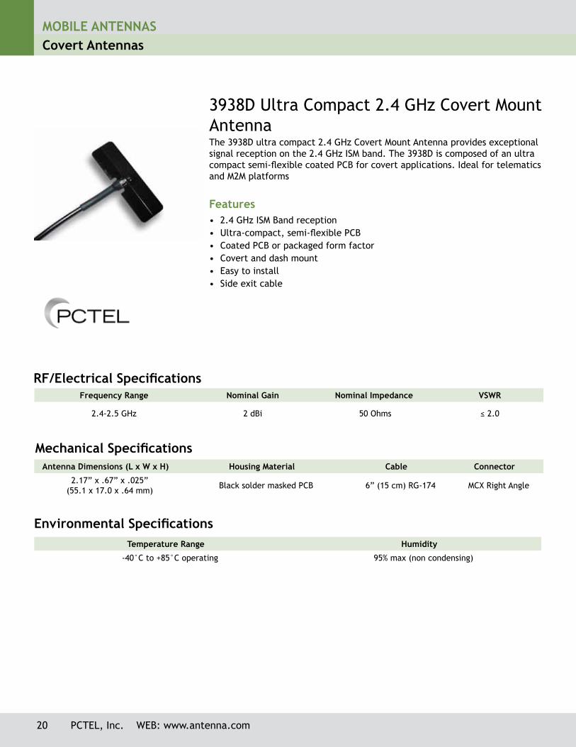
3938D Ultra Compact 2.4 GHz Covert Mount AntennaThe 3938D ultra compact 2.4 GHz Covert Mount Antenna provides exceptional signal reception on the 2.4 GHz ISM band. The 3938D is composed of an ultra compact semi-flexible coated PCB for covert applications. Ideal for telematics and M2M platforms
Features• 2.4 GHz ISM Band reception• Ultra-compact, semi-flexible PCB• Coated PCB or packaged form factor• Covert and dash mount• Easy to install• Side exit cable
Frequency Range Nominal Gain Nominal Impedance VSWR
2.4-2.5 GHz 2 dBi 50 Ohms ≤ 2.0
RF/Electrical Specifications
Environmental Specifications Temperature Range Humidity
-40°C to +85°C operating 95% max (non condensing)
Antenna Dimensions (L x W x H) Housing Material Cable Connector
2.17” x .67” x .025”(55.1 x 17.0 x .64 mm) Black solder masked PCB 6” (15 cm) RG-174 MCX Right Angle
Mechanical Specifications

MOBILE ANTENNASGPS L1 Multi-band Antennas
GPS HIGH PERFORMANCE PLATFORMThe GPSHPSM high performance GPS Multi-Band antenna platform is PCTEL’s most durable and versatile design for vehicular applications. This platform of-fers multi-band coverage, superior GPS LNA technology, easy to install design, and “top shelf” materials to provide maximum durability and performance for Mission Critical communications.
Features• No tune, multi-band coverage: 700/800 MHz Public Safety, 800 MHz Cellular/
SMR, 900 MHz GSM/ISM, 1800-2100 MHz GSM/PCS, 3G, 4G, 2.4/5.8 GHz WiFi and 2.3-5.8 GHz Public Safety and WiMAX broadband wireless frequencies
• Metal 3/4-inch stud mount with slotted jam nut provides single cable exit for easier installation and/or antenna replacement
• Attractive low profile design for maximum installation flexibility without antenna orientation restrictions
• IP67 compliant design with custom overmolded gasket provides maximum protection against water or dust ingress under severe environmental condi-tions
• High performance, low loss cable and high quality connectors for maximum RF system efficiency
• UV resistant black or white housing options complement most vehicular aesthetic requirements
Electrical Specifications - GPS AntennaFrequency Band:
1575.42 MHz (GPS L1)
Amplifier Gain:26 dB +/- 3 dBic
Nominal Impedance:50 ohms
Output VSWR:1.5:1 typical
DC Current:20 mA Nominal; < 30 mA @ -40°C to +85° C
DC Voltage:3-13.5 V
Noise Figure:1.8dB Typical
Out-of-Band Signal Rejection:> 40 dB rejection @ +/- 50 MHz from center frequency
Electrical Specifications - RF Antennas
Available Models: GPSHPSM/SM/SM (Black Radome)
WGPSHP (White Radome)
Operating Frequencies Polarization Nominal
ImpedanceGain1
(Typical)Maximum
Power VSWR
Voice/Data RF Element
698-2500 MHz3300-3800 MHz
Vertical, linear 50 ohms 4-5 dBi 50 watts < 2.0:1
Broadband Wireless
RF Element
1.7-2.8 GHz4.9-5.9 GHz
Vertical, linear 50 ohms 4-5 dBi 50 watts < 2.0:1
1 Measured on a 4-foot diameter ground plane. Gain value is measured at the base of the antenna (no cable loss included).
Mechanical and Environmental Specifications
Dimensions Coax (3) Connectors
5.2” OD x 2.8” H(132 OD x 71 H mm)
17 feet Pro-Flex Plus 195 (Voice/Data/WiMAX elements); 17 feet Pro-Flex Plus 195 (Broadband Wireless Element);
17 feet RG-174/U (GPS L1)
SMA Plug (Male)
standard
Radome /Baseplate Construction Mounting Method Operating / Storage
TemperatureIngress
Protection
Black2 or White UV stable CYCOLOY C6200
Zinc baseplate over-molded with black TPE,
SANTOPRENE gasket
3/4-inch hole, 3/4-inch long (.75”) zinc stud mount with dual jam
nuts (included)
-40°C to +85°C IP67
PCTEL, Inc. WEB: www.antenna.com 61
For other connector options, please refer to GPS Multi-Band Mobile Antenna Configurator Part Number Guide for Quad-Band Models.

MOBILE ANTENNASGPS L1 Multi-band Antennas
GPS HIGH PERFORMANCE MULTI-BAND MIMOThe GPSHPMIMO GPS Multi-Band antenna utilizes PCTEL’s most durable and versatile design for vehicular applications requiring MIMO for WiFi applications. This platform offers multi-band coverage, superior GPS LNA technology, an easy to install design, and “top shelf” materials to provide maximum durability and performance for mobile data and video communications.
Features• No tune, multi-band coverage: 700/800 MHz Public Safety, 800 MHz Cellular/
SMR, 900 MHz GSM/ISM, 1800-2100 MHz GSM/PCS, 3G, 4G, 2.4/5.8 GHz WiFi and 2.3-5.8 GHz Public Safety and WiMAX broadband wireless frequencies
• Metal 3/4-inch stud mount with slotted jam nut provides single cable exit for easier installation and/or antenna replacement
• Attractive low profile design for maximum installation flexibility without antenna orientation restrictions
• IP67 compliant design with custom overmolded gasket provides maximum protection against water or dust ingress under severe environmental condi-tions
• High performance, low loss cable and high quality connectors for maximum RF system efficiency
• UV resistant black or white housing options complement most vehicular aes-thetic requirements
Electrical Specifications - RF AntennasModel
GPSHPMIMOOperating
Frequencies Polarization Nominal Impedance
Typical Gain1
Max. Power VSWR
Voice/Data RF Element
698-2500 MHz3300-3800 MHz
Vertical, linear 50 ohms 1-2 dBi
2-3 dBi50
Watts< 2.0:1
Broadband Wireless RF Element #1
1.7-2.8 GHz4.9-5.9 GHz
Vertical, linear 50 ohms 2-3 dBi
3-4 dBi50
Watts< 2.0:1
Broadband Wireless RF Element #2
1.7-2.8 GHz4.9-5.9 GHz
Horizontal, linear 50 ohms 2-3 dBi
3-4 dBi50
Watts< 2.0:1
Mechanical Specifications
Dimensions Coax (4) Connectors
5.2” OD x 2.8” H(132 OD x 71 H mm)
17 feet Pro-Flex Plus 195 (Voice/Data RF Element;17 feet Pro-Flex Plus 195 (Broadband Wireless Element #1) 17 feet Pro-Flex Plus 195 (Broadband Wireless Element #2)
17 feet RG-174/U (GPS L1)
SMA Plug (Male)
standard
Mechanical and Environmental SpecificationsRadome /
Baseplate Construction Mounting Method Operating / Storagetemperature
IngressProtection
Black, UV stableCYCOLOY C6200 Radome
Zinc baseplate over-molded with black TPE,
SANTOPRENE gasket
3/4-inch hole, 3/4 inch long (.75”) zinc stud mount with dual jam
nuts (included)
-40°C to +85°C IP67
Electrical Specifications GPS AntennaFrequency Band:
1575.42 MHz (GPS L1)
Amplifier Gain:26 dB +/- 3 dBic
Nominal Impedance:50 ohms
Output VSWR:1.5:1 typical
DC Current:20 mA Nominal; < 30 mA @ -40°C to +85° C
DC Voltage:3-13.5 V
Noise Figure:1.8dB Typical
Out-of-Band Signal Rejection:> 40 dB rejection @ +/- 50 MHz from center frequency
1 Measured on a 4-foot diameter ground plane. Gain value is measured at the base of the antenna (no cable loss included).
Radome shown in white. Black radome is standard.
62 PCTEL, Inc. WEB: www.antenna.com
For other connector options, please refer to GPS Multi-Band Mobile Antenna Configurator Part Number Guide for Quad-Band Models.
MOBILE ANTENNASGPS L1 Multi-band Antennas
PCTEL, Inc. WEB: www.antenna.com 63
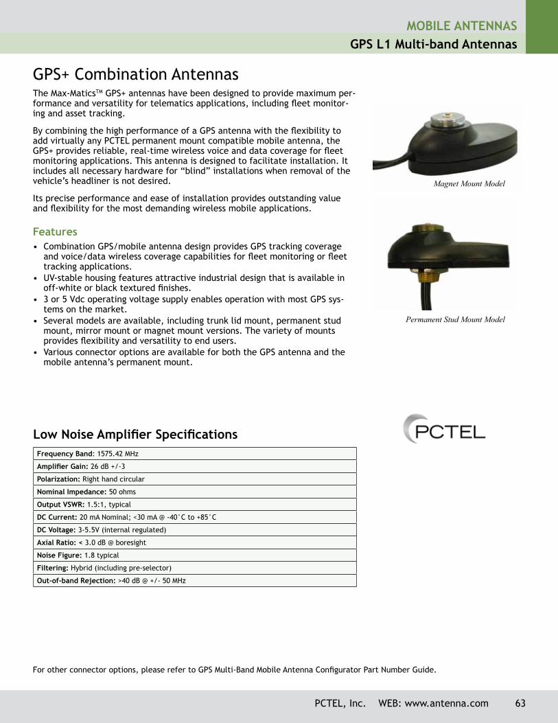
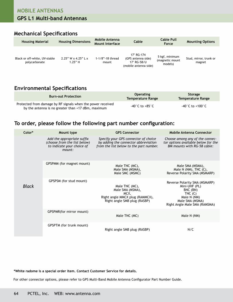
GPS+ Combination AntennasThe Max-MaticsTM GPS+ antennas have been designed to provide maximum per-formance and versatility for telematics applications, including fleet monitor-ing and asset tracking.
By combining the high performance of a GPS antenna with the flexibility to add virtually any PCTEL permanent mount compatible mobile antenna, the GPS+ provides reliable, real-time wireless voice and data coverage for fleet monitoring applications. This antenna is designed to facilitate installation. It includes all necessary hardware for “blind” installations when removal of the vehicle’s headliner is not desired.
Its precise performance and ease of installation provides outstanding value and flexibility for the most demanding wireless mobile applications.
Features• Combination GPS/mobile antenna design provides GPS tracking coverage
and voice/data wireless coverage capabilities for fleet monitoring or fleet tracking applications.
• UV-stable housing features attractive industrial design that is available in off-white or black textured finishes.
• 3 or 5 Vdc operating voltage supply enables operation with most GPS sys-tems on the market.
• Several models are available, including trunk lid mount, permanent stud mount, mirror mount or magnet mount versions. The variety of mounts provides flexibility and versatility to end users.
• Various connector options are available for both the GPS antenna and the mobile antenna’s permanent mount.
Low Noise Amplifier SpecificationsFrequency Band: 1575.42 MHz
Amplifier Gain: 26 dB +/-3
Polarization: Right hand circular
Nominal Impedance: 50 ohms
Output VSWR: 1.5:1, typical
DC Current: 20 mA Nominal; <30 mA @ -40°C to +85°C
DC Voltage: 3-5.5V (internal regulated)
Axial Ratio: < 3.0 dB @ boresight
Noise Figure: 1.8 typical
Filtering: Hybrid (including pre-selector)
Out-of-band Rejection: >40 dB @ +/- 50 MHz
For other connector options, please refer to GPS Multi-Band Mobile Antenna Configurator Part Number Guide.
Magnet Mount Model
Permanent Stud Mount Model
64 PCTEL, Inc. WEB: www.antenna.com
MOBILE ANTENNASGPS L1 Multi-band Antennas
Color* Mount type GPS Connector Mobile Antenna Connector
Black
Add the appropriate suffix (choose from the list below) to indicate your choice of
mount:
Specify your GPS connector of choice by adding the connector abbreviation
from the list below to the part number.
Choose among any of the connec-tor options available below for the
BM mounts with RG-58 cable:
GPSPMM (for magnet mount)Male TNC (MC),
Male SMA (MSMA), Male SMC (MSMC)
Male SMA (MSMA), Male N (NM), TNC (C),
Reverse Polarity SMA (MSMARP)
GPSPSM (for stud mount)
Male TNC (MC), Male SMA (MSMA),
MCX, Right angle MMCX plug (RAMMCX),
Right angle SMB plug (RASBP)
Reverse Polarity SMA (MSMARP)Mini-UHF (PL)
BNC (BN)TNC (C)
Male N (NM)Male SMA (MSMA)
Right Angle Male SMA (RAMSMA)
GPSPMR(for mirror mount)Male TNC (MC) Male N (NM)
GPSPTM (for trunk mount)Right angle SMB plug (RASBP) N/C
To order, please follow the following part number configuration:
Burn-out Protection Operating Temperature Range
Storage Temperature Range
Protected from damage by RF signals when the power received by the antenna is no greater than +17 dBm, maximum -40°C to +85°C -40°C to +100°C
Environmental Specifications
Housing Material Housing Dimensions Mobile Antenna Mount Interface Cable Cable Pull
Force Mounting Options
Black or off-white, UV-stable polycarbonate
2.25” W x 4.25” L x 1.25” H
1-1/8”-18 thread mount
17’ RG-174 (GPS antenna side)
17’ RG-58/U (mobile antenna side)
5 kgf, minimum (magnetic mount
models)
Stud, mirror, trunk or magnet
Mechanical Specifications
*White radome is a special order item. Contact Customer Service for details.
For other connector options, please refer to GPS Multi-Band Mobile Antenna Configurator Part Number Guide.
PCTEL, Inc. WEB: www.antenna.com 65
MOBILE ANTENNASGPS L1 Multi-band Antennas
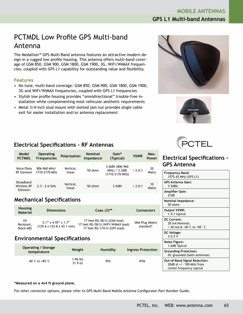
PCTMDL Low Profile GPS Multi-band AntennaThe Medallion™ GPS Multi-Band antenna features an attractive modern de-sign in a rugged low profile housing. This antenna offers multi-band cover-age of GSM 850, GSM 900, GSM 1800, GSM 1900, 3G, WiFi/WiMAX frequen-cies, coupled with GPS L1 capability for outstanding value and flexibility.
Features• No tune, multi-band coverage: GSM 850, GSM 900, GSM 1800, GSM 1900,
3G and WiFi/WiMAX frequencies, coupled with GPS L1 frequencies• Stylish low profile housing provides “omnidirectional” trouble-free in-
stallation while complementing most vehicular aesthetic requirements• Metal 3/4-inch stud mount with slotted jam nut provides single cable
exit for easier installation and/or antenna replacement
Electrical Specifications - RF AntennasModel
PCTMDLOperating
Frequencies Polarization Nominal Impedance
Gain* (Typical) VSWR Max.
Power
Voice/Data RF Element
806-960 MHz/1710-2170 MHz
Vertical, linear 50 ohms
2.8dBi (806-960 MHz) / 3.3dBi
(1710-2170 MHz)< 2.0:1 20
Watts
Broadband Wireless RF
Element2.3 - 2.6 GHz Vertical,
linear 50 ohms 3.9dBi < 2.0:1 10 Watts
*Measured on a 4x4 ft ground plane.
Mechanical SpecificationsHousing Material Dimensions Coax (3)** Connectors
UVResistant, Black ABS
5.1” x 4.95” x 1.7”(129.6 x 125.8 x 43.1 mm)
17 feet RG-58/U (GSM lead)17 feet RG-58/U (WiFi/WiMAX lead)
17 feet RG-174/U (GPS lead)
SMA Plug (Male) standard*
Environmental SpecificationsOperating / Storage
temperature Weight Humidity Ingress Protection
-40°C to +85°C 1.96 lbs31.9 oz 95% IP56
Electrical Specifications - GPS AntennaFrequency Band:
1575.42 MHz (GPS L1)
GPS Antenna Gain:3.5dBic
Amplifier Gain:27dB
Nominal Impedance:50 ohms
Output VSWR:1.5:1 typical
DC Current:20 mA Nominal; < 30 mA @ -40°C to +85° C
DC Voltage:3-5.5 V
Noise Figure:1.6dB Typical
Grounding Protection:DC grounded (both antennas)
Out-of-Band Signal Rejection:20dB @ +/- 100 MHz from center frequency typical
For other connector options, please refer to GPS Multi-Band Mobile Antenna Configurator Part Number Guide.

MOBILE ANTENNASGPS L1 Multi-band Antennas
66 PCTEL, Inc. WEB: www.antenna.com
“Sharkfin” Multi-band Antenna
Technical Data Maximum Power:
10 watts
Polarization:Right hand circular
Input Impedance:50 ohms
VSWR:< 1.8:1 (GPS)< 2.0:1 (RF)
Azimuth Coverage (GPS):360°
Elevation Coverage (GPS):Hemispherical
Operating Supply Voltage:2.7 - 5.5 V
Housing:Black, UV protected ABS
Housing Dimensions (major axis x minor axis x height):
3.8 x 2.4 x 2.8 inches97 x 60 x 70 mm
Cable:10 feet RG-174
Mount Method:Through hole mounting
The Sharkfin antennas provide multi-band omnidirectional coverage in an attrac-tive, low profile housing. The tri-band and quad-band models also provide GPS navigation support capability. Their low profile through-hole footprint offers an attractive antenna design that provides optimal sealing for leakage resistance.
Features• Low, aerodynamic profile eliminates wind noise commonly experienced with
external mount vehicular applications• Overmolded gasket design provides optimal sealing from condensation and
water ingress• Integrated antenna mast design provides secure installation to the vehicle• UV stability for outdoor applications• GPS navigation support on select models
Model* Frequencies Covered Number of Pigtails
GPSQB AMPS/PCS/GPS/WiFi 3
GPSTB AMPS/PCS/GPS 2
Sharkfin Multi-band Roof Mount Antennas
Operating Frequency Nominal Gain Gain - Antenna Element Noise Figure
L1: 1575.42 24 dB 3.5 dBic 2.0 dB nominal
Model Operating Frequencies Antenna Gain
GPSQB and GPSTB 824-896 MHz (AMPS); 1850-1990 MHz (PCS) 2.4-2.5 GHz (WiFi) (GPSQB only) Unity
Operating Temperature Range Humidity Rating Ingress Protection
-40° C to +85° C 95% IP56
GPS Antenna Electrical Specifications
Environmental Specifications
Multi-band Antenna Electrical Specifications
Base Model GPS Connector Code AMPS/PCS Connector Code
Wi-Fi Connector Code
Example:GPSQB
Choose among:Right angle SMB Plug (RASBJ)Male SMA (MSMA)Female FME (FFME)
Choose among:Male SMA (MSMA)Male TNC (C)Female TNC (FC)Female FME (FFME)
Choose among: Reverse Polarity TNC (RPC) Male TNC (C) Reverse Polarity Male SMA (RPMSMA)
*To order, please follow the following part number configuration:
For other connector options, please refer to GPS Multi-Band Mobile Antenna Configurator Part Number Guide.