new antennas for mobile technology - antenna · pdf filenew antennas for mobile technology ......
TRANSCRIPT

Bob Giometti
Vice President R&D and Engineering, SkyCross
New Antennas for Mobile Technology
Presented at the Antenna Systems Conference
December 12-13, 2013
Las Vegas, NV

a
Contents
Page 2
1. Introduction
2. LTE-A and the Mobile Device Antenna
3. LTE-A: Impact on the Antenna System
a. Requirements
b. Carrier Aggregation
c. Drivers for Antenna Tuning
4. Enabling Technologies
a. Aperture Tuning
b. Tunable Match Network
c. Hybrid Approach
d. Co-location of antennas
e. Isolated Mode Antennas (iMAT)
- Beam Forming Application
5. Summary

Introduction
3

- Over 20 years experience in the wireless industry
- Mobile phone product development at Motorola/Google
- Electrical design lead for the original RAZR
- BSEE/MSEE Illinois Institute of Technology
- Joined SkyCross as VP of R&D and Engineering Jan. 2013
Background/Bio
Page 4

LTE- A and the Mobile
Device Antenna
5

• Many bands (40+ and counting….)– 700 MHz in US (sub-bands for AT&T and Verizon) – AWS (2.1/1.7 GHz) in US – 790-862 MHz in Europe– 2.6 GHz FDD – mainly in Europe– 2.6 GHz TDD – China, Europe– 2.3 GHz TDD – China, Korea, India– 600MHz on the way!
• GPS, BT, FM, NFC,…
• WiFi (Dual Band)
• Tx Diversity
• MIMO 2x2, 3x3, 4x4,…
• Carrier Aggregation– Low/Low, Low/High, High/High
LTE-A: Squeezing Even More Into The Mobile Device
Page 6

Challenges facing today’s Mobile Device Antenna Engineer
Page 7
Traditional antenna performance is inadequate to meet market demands for:
Increasing number of frequency bands (4G/LTE)
Increased data traffic clogged networks
Real life use cases (head, hand, slider phone)
Thinner phones Smaller antennas Quality of Service challenges
Bands of Interest vary by: Country / Region Network provider Protocol Use case
Need for advanced adaptiveantenna/RF solutions

“Advanced Smart Antennas” provide improved RF
Performance & Increased Flexibility
Page 8
Fewer Dropped or
Missed Calls
Greater Cell Site
Area Coverage
~ Fewer cell sites;
~ Better spectrum utilization
~ Reduced Infrastructure costs
Faster Data Rates
Faster Time To Market
~ More Predictable Results
~ Fewer SKU’s
Thinner, More Stylish Phones
Reduced Power Consumption
~ Increased battery life

LTE-A: Impact on the
Antenna System
9

Page 10
Enables more users, more applications,
and a better experience
Source: Rysavy Research/4G Americas, 2012
LTE 2010 to 2012
•5 or 10 MHz Radio Channels
•2X2 Multiple Input Multiple
Output (MIMO)
LTE- A 2013 to 2016
Higher Capacity/Throughput and/or Efficiency
•Wider Radio Channels: 20 MHz
•Carrier Aggregation: up to 100 MHz
•Advanced Antenna Configurations
•More Advanced MIMO (Higher Order, Multi-User,
Higher Mobility)
•Coordinated Multipoint Transmission
•Het-nets (Microcells/Picocells/Femtocells)

• Easiest way to arrange aggregation: use contiguous component carriers
within the same operating frequency band (as defined for LTE), so called
intra-band contiguous.
• May not always be possible, due to frequency allocation scenarios.
• For non-contiguous allocation it could either be intra-band, i.e. the component
carriers belong to the same operating frequency band, but are separated by a
frequency gap, or it could be inter-band, in which case the component carriers
belong to different operating frequency bands.
Carrier Aggregation Considerations
Page 11

• LTE smartphones are challenged to achieve tightening carrier
performance expectations
– 4G LTE speeds/capacity require MIMO (multiple LTE antennas)
– Growing number of operating frequency bands (number of antennas)
– Aggressively styled device form-factors (constrained space)
• OEMs seeking new technical solutions to address challenges
– Tunable antenna solutions seen as the desired approach
– Progressive OEMs already initiating smartphone architectures that
support tunable antenna modules
• LTE-A Requirements
– Carrier Aggregation
– Higher Levels of MIMO
– Tx Diversity
LTE-A Drivers for Antenna Tunability
Page 12

Enabling Technologies
13

Antenna Tuning Technologies
14

Tunable vs. Passive Antennas
Page 15
• Integrates tuning elements,
antenna, and interface
• Smaller size (smaller than
conventional passive antennas at
same efficiency) or higher gain in
same size to reduce Tx power
consumption (increased battery
life)
• Separate from and
complementary to feed-point
impedance matching
• Supports Carrier Aggregation
requirements
• Primary/secondary antennas can
be co-located for greater space
reduction
• Potential to simplify filter circuits
• Simple 1 or 2 bit interface and
control

Motivation for Tunable Antennas
1. Greater band coverage +MIMO in accepted form factor allocated
space
2. Smaller Antenna: 1000 cubic millimeters or less (handset
OEMs)(need more tuning states)
3. Head/Hand Effect mitigation (requires sensor and algorithm)
(Operators)
4. Higher ASP stemming from integration of antenna and tuning
elements/control (Antenna Suppliers)
5. Lower VSWR (PA Suppliers)
6. Reduced Filter Requirements (Filter suppliers)
Page 16

Aperture Tuning – Integrates tuning element, antenna,
and interface
– Antenna resonance is changed directly by the tuning element.
– Allows antenna to be made smaller or cover more bands than with passive antenna
– Simple interface and control to achieve open loop coverage on a band-by-band basis
– Often used with tuning devices such as switches or DTCs for open or closed loop control.
– Can be thought of as a “coarse tuner”
Tunable Matching Network – Used to improve VSWR match to
antenna.
– Not considered as producing optimal
radiation efficiency compared to
Aperture Tuning
– Improves power coupled to antenna
over frequency of operation and
under varying usage or
environmental conditions
– More complex interface generally
with 6 or more bits of control
– Can use analog tuning devices such
as BST and Varactor diodes, may be
open or closed loop
– Can be thought of as a “fine tuner”
Aperture Tuning (AT) vs. Tunable Matching Network (TMN)
Page 17

Efficiency Comparison Between Passive Broad Band
and State-Tuned-Aperture Antennas
Page 18
State 1
State 2
Broad Band
Low Bands High Bands
Significant improvement in low
band performance
>2 dB
Minimal impact to high band
performance
~0.8 dB

Aperture Tuning vs. Tunable Matching Network
Page 19
Natural antenna/device bandwidth 824-960 MHz
TMN improves
efficiency at 750
MHz compared to no
match
3dB
delta TMN
Improves
match at
750 MHz

Aperture Tuning (AT) Advantage
Page 20
Natural antenna/device bandwidth 824-960 MHz
AT match at 750 MHz has broader bandwidth vs. TMN

Page 21
Hybrid Approach: Aperture + Match Tuning
RF
(Port 1)
Microcontroller
Control Algorithm
Flash
Memory
RF
(Port 2)
Tunable Matching Network
(Fine Tuner)
Optimize Performance
Diversity Aperture
Tuned Antenna
(Coarse Tuner)
Band Selection
MIPI RFFE GPIO Control
Tunable Matching Network
(Fine Tuner)
Optimize Performance
Diversity Aperture
Tuned Antenna
(Coarse Tuner)
Band Selection

Antenna Co-Location
22

Page 23
Antenna Proximity Problem
• Far apart– Negligible coupling between
antennas
– spatial separation makes antenna patterns unique
– How far: generally more than about half wavelength (17 cm at 900 MHz) – size not feasible for many consumer products
• Close together - coupling between antennas may
be a problem (RX saturation or desense, TX distortion)
- coupling hurts radiation efficiency as power goes into neighboring antenna and not to far field
- patterns lose uniqueness and are highly correlated (loss of MIMO capacity or loss of diversity gain)
- Reality of many consumer products
Antenna starts to couple
more to its neighbor
than to the far-field

Page 24
The MIMO Antenna Solution for 4G
: Isolated Mode Antenna Technology
• iMAT is a patented technology that allows a single antenna
structure to behave like multiple antennas through the use of
multiple feed points.
• Each feed point accesses the single antenna as if it consisted of 2, 3,
or more independent antennas that are highly isolated with superior
link performance gain.
• This compact solution is applicable to any mobile device! iMAT
supports legacy networks and is essential for next generation
protocols that require diversity or MIMO.
Patented Technology

Page 25
Enables Multiple Antennas in Small Spaces
Antenna Requirements
• Diversity/MIMO
• High isolation
• High radiation efficiency
• Low correlation coefficient
• Small size
d
Conventional
Smart Antenna
Approach
Isola
tion d
B
0
-10
-20
-30Frequency
60
50
40
30
Effic
iency %
ISO
EFF
SkyCross iMAT
Solution
Isola
tion d
B
0
-10
-20
-30Frequency
60
50
40
30
Effic
iency %
ISO
EFF
1 2
The iMAT solution offers high efficiency, superior isolation, and low correlation coefficient
while maintaining equivalent return loss, with a single antenna!
Technology Applications
• WiFi and/or WiMAX
• 4G/LTE
• HSDPA / HSUPA
• 1XEVDO
• 802.11n, 802.11ac
• Mobile video (CMMB, T-DMB, DVB-H)
SkyCross Antenna
Technology
Breakthrough!
1 3 . . .3 . . .
d
2

Page 26
iMAT Technology: Modal Interpretation
• The near fields are overlapping, but two unique antenna modes still exist
• In the simple case there are two resonant modes:– common mode: radiates similar to a lone
antenna would as the spacing becomes small
– differential mode: less effective antenna mode as the spacing decreases – the radiation resistance of this mode is diminishing as the antennas are brought closer
• Two physically separate antennas are not optimal in most cases – this system tends to utilize mostly one mode, the common mode
common
differential
Fundamental
Modes

Page 27
iMAT: Far-Field Patterns
• Each resonance mode has a unique far field pattern
• With iMAT approach each antenna port couples to a different combination of the two fundamental modes
• The resulting far-field patterns are also unique to each other resulting in low ECC
Combination
- =
+ =
Pattern phase reversal
Farfield pattern
from Port 1
Farfield pattern
from Port 2
Common
Mode
Differential
Mode

Page 28
iMAT: Concurrency of Isolation and ECC
• With iMAT Port-to-port isolation and low far-field correlation are obtained from the same design optimization at the same frequency
• Both result from the condition where the near fields associated with Port 1 are orthogonal from those associated with Port 2
• The proper conditions are achieved through resonance and so are inherently optimized to a particular frequency band or bands
Port-to-Port Coupling
Pattern Correlation
frequency
frequency

State 1 State 2
• Aperture tuning in SkyCross tunable antenna modules permits the actual radiating elements to be configured for optimal performance at each desired frequency band
• SkyCross ST-iMAT and Aperture Tuning deliver: Smaller size
Improved device performance
Network improvement (fewer dropped calls, increased network capacity)
Superior performance versus simple feed-point matching
SkyCross ST-iMAT™ (State-Tuned iMAT Antenna Module for Smartphone)
VersiTune-LTE™ Tunable Antenna Module
Smartphone
Implementation
iMAT
Radiating
Elements
Tunable
Antenna
Module

Tunable iMAT “Isolation Notch” Drives Multiband
Antenna Performance
iMAT design allows “control” of the isolation between ports. Drives higher efficiency and lower correlation coefficient
• Isolation is a measure of signal interference separation from one feed point to the other
• Correlation coefficient is the degree to which the two RF signals are distinct from each other

Page 31
LTE-700 Corner to Corner
Conventional Antenna Design
VSWR: <2:1 Efficiency:
30-40%
CC:
>0.8Coupling:
-4dB
Patterns
almost
identical

Page 32
iMAT LTE-700 Antenna Design
VSWR
<2.2:1
Isolation:
<-13 dB
Efficiency
50-58%
CC:
<0.35
Significantly
different
patterns
50x100mm
GP
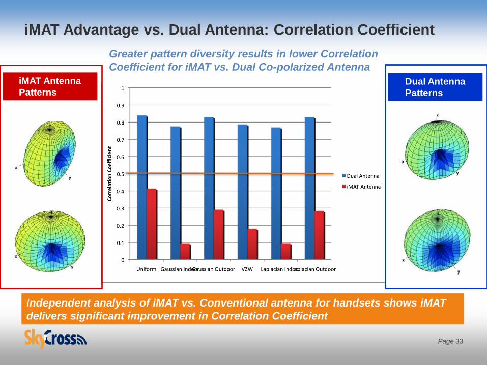
iMAT Advantage vs. Dual Antenna: Correlation Coefficient
iMAT Antenna
PatternsDual Antenna
Patterns
Greater pattern diversity results in lower Correlation
Coefficient for iMAT vs. Dual Co-polarized Antenna
Independent analysis of iMAT vs. Conventional antenna for handsets shows iMAT
delivers significant improvement in Correlation Coefficient
Page 33

Multiband Antenna Efficiency: ST-iMAT
State 1 State 2 State 3 State 4 State 5 State 6
Sin
gle
Po
rt O
nlyPrimary
Spec
Diversity
Spec
Measured Data: State Tuned iMAT configuration covering all LTE and Legacy 3G bands in 6 tuning states

• Phone chassis: ~58x120mm
• Modular Antenna: x=59mm, y=9.5mm (from display edge), z=3.7mm
Antenna volume (incl. keep out) = 2075mm3
Fully populated antenna module with speaker, microphone, USB3
Versitune-LTE Antenna Speaker Module Design Example
y =9.5mm
Antenna Elements
Flex PCB Antenna
(Double Sided FPCB)
Plastic Carrier
With Speaker Box
Embedded
Speaker
Audio Port
Microphone
USB Connector
Tuning
Components
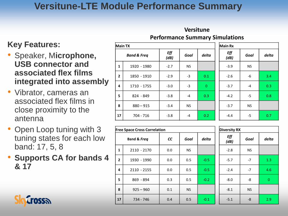
Versitune-LTE Module Performance Summary
Key Features:
• Speaker, Microphone, USB connector and associated flex films integrated into assembly
• Vibrator, cameras an associated flex films in close proximity to the antenna
• Open Loop tuning with 3 tuning states for each low band: 17, 5, 8
• Supports CA for bands 4 & 17
VersitunePerformance Summary Simulations
Main TX Main Rx
Band & FreqEff
(dB)Goal delta
Eff(dB)
Goal delta
1 1920 - 1980 -2.7 NS -3.9 NS
2 1850 - 1910 -2.9 -3 0.1 -2.6 -6 3.4
4 1710 - 1755 -3.0 -3 0 -3.7 -4 0.3
5 824 - 849 -3.8 -4 0.3 -4.2 -5 0.8
8 880 – 915 -3.4 NS -3.7 NS
17 704 - 716 -3.8 -4 0.2 -4.4 -5 0.7
Free Space Cross Correlation Diversity RX
Band & Freq CC Goal deltaEff
(dB)Goal delta
1 2110 - 2170 0.0 NS -2.8 NS
2 1930 - 1990 0.0 0.5 -0.5 -5.7 -7 1.3
4 2110 - 2155 0.0 0.5 -0.5 -2.4 -7 4.6
5 869 - 894 0.3 0.5 -0.2 -8.0 -8 0
8 925 – 960 0.1 NS -8.1 NS
17 734 - 746 0.4 0.5 -0.1 -5.1 -8 2.9

Versitune LTE Efficiency - Primary/Secondary Port
Primary Port
Secondary Port
Performance data includes speaker, cameras, microphone, vibrator, micro USB
and associated flex interconnects in the antenna near field
Tuning
states 1,2,3

Versitune LTE Coupling (S12) - Primary/Secondary Port
Primary Port
Secondary Port
Performance data includes speaker, cameras, microphone, vibrator, micro USB
and associated flex interconnects in the antenna near field

Versitune LTE - Envelope Correlation
Primary
Secondary
Performance data includes speaker, cameras, microphone, vibrator, micro USB
and associated flex interconnects in the antenna near field

iMAT 2x2
Antenna
iMAT 2x2 Beam Forming Application

Page 41
Antenna Beam Forming Problem for Handset Application
• Beam forming is accomplished by combining signals in two or more antennas at different phases
• For conventional antennas, as antenna separation decreases, the benefits of beam forming diminish due to the detrimental effects of antenna mutual coupling
• The separation between antennas, in terms of wavelength, is small for handset and mobile device applications (typically < 0.1 wavelength)
~
~
Antenna Array Combined Signal
Phase Shifter
s <0.1 wavelength at
cellular
frequencies

Page 42
• A balanced iMAT design may be well suited for beam forming applications
• Both ports of iMAT antenna can be driven simultaneously
• Applying the same RF signal to both ports with a variable relative phase delay enables a beam forming solution
• Beam forming can provide 3 dB signal gain at the tower for same client device TRP
• Because there are two PAs,
each needs to provide only
half the total output power of the
traditional PA.
Port 1 Excitation
Ф
TX
PA
PA
iMAT antenna
Beam Forming – iMAT Technology

Page 43
Beam Forming Application
Analysis Comparing iMAT to Conventional Antennas
Analysis Result – single iMAT antenna produces better beam forming gain than a pair of
conventional dipoles
Improvement due to iMAT

Summary
1. LTE-A requirements are driving the need for new,
more complex antenna technologies
2. Close attention to the antenna early in the design
stage is even more critical due to higher levels of
complexity
3. Antenna designs that may utilize a combination of
technologies can be used as a competitive
advantage that allows for product differentiation
Page 44

Page 45
This is truly an exciting time to be a
mobile device antenna designer!
THANK YOU!