mobile flm transceivers - ncjrs · u.s. department of justice national institute of justice mobile...
TRANSCRIPT
U.S. Department of Justice National Institute of Justice
Mobile FlM Transceivers NIJ Standard-0210.00

ABOUT THE TECHNOLOGY ASSESSMENT PROGRAM
The Technology Assessment Program sponsored by the Office of Development, Testing, and Dissem- ination of the National Institute of Justice (NU), U.S. Department of Justice. The program responds to the .
mandate of the Justice System Improvement Act of 1979, which created NU and directed it to encourage research and development to improve the criminal justice system and to disseminate the results to Federal, State, and local agencies.
The Technology Assessment Program is an app1i;ed research effort that determines the technological needs of justice system agencies, sets minimum performance standards for specifk devices, tests commercially available equipment against those standards, and disseminates the standards and the test results to criminal justice agencies nationwide and internationally.
The program operates through: The Technology Assesment Angmm A d v b y Council VAPAC) consisting of na'tionallY recognized crim-
inal justice practitioners from Federal, State, and local agencies, which assesses technological needs and sets priorities for research programs and items to be evaluated and tested.
The Low Enforement Standards Lobomtory (LESL) at the National Burkau of Standards, which develops voluntary national performance standards for compliance testing to ensure that individual items of equipment are suitable for use by criminal justice agencies. The standards are based upon laboratory testing and evaluation of representative samples of each item of equipment to determine the key attributes, develop test methods, and establish minimum performance requirements for each essential attribute. In addition to the highly technical standards, LESL also produces user guides that explain in nontechnical terms the capabilities of available equipment.
The Terhnology Assessment Pmgmm Information Center PAPIC) operated by a grantee, which supervises a national compliance testing program conducted by independent agencies. The standards developed by LESL serve as performance benchmarks against which commercial equipment is measured. The facilities, personnel, and testing capabilities of the independent laboratories are evaluated by LESL prior to testing each item of equipment, and LESL helps the Information Center staff review and analyze data. Test results are published in Consumer Product Reports designed to help justice system procurement officials make informed purchasing decisions.
Publications issued by the National Institute of Justice, including those of the Technology Assessment Program, are available from the National Criminal Justice Reference Service (NCJRS), which serves as a central information and reference source for the Nation's criminal justice community. For further information, or to register with NCJRS, write to the National Institute of Justice, National Criminal Justice Reference Service, Washington, DC 2053 1.
James K Stetwart, Director National Institute of Justice

U.S. Department of Justice National Institute of Justice
Mobile FM Transceivers NIJ Standard-0210.00
May 1986
U.S. DEPARTMENT OF JUSTICE National Institute of Justice
James K. Stewart, Director
ACKNOWLEDGMENTS
This standard was formulated by the Law Enforcement Standards Laboratory (LESL) of the National Bureau of Standards under the direction of Marshall J. Treado, Program Manager for Communications Systems, and Lawrence K. Eliason. Chief of LESL. NBS Electromagnetic Fields Division staff membm responsible for the preparation of the standard were Charles K. S. Miller, Division Chief; Harold E. Taggart. Group Leader; and William D. knsema Acknowledgment is given to previous work in this fteld by the Associated Public-Safety Communications Officm, Inc.. and the Electronic Industries Association. This standard has been reviewed and approved by the Technology Assessment Program Advisory Council.
The technical effort to develop this standard was conducted under Interagency Agreement LEAA-J-MA-02 1-3, Roject No. 8006.

FOREWORD
This document, NIJ Standard-0210.00, Mobile FM Transceivers, is an equipment standard developed by the Law Enforcement Standards Laboratory of the National Bureau of Standards. It is produced as part of the Technology Assessment Program of the National Institute of Justice. A brief description of the program appears on the inside front cover.
This standard is a technical document that specifies performance and other requirements equipment should meet to satisfy the needs of criminal justice agencies for high quality service. Purchasers can use the test methods described in this standard to determine whether a particular piece of equipment meets the essential requirements, or they may have the tests conducted on their behalf by a qualified testing laboratory. Pro- curement officials may also refer to this standard in their purchasing documents and require that equipment offered for purchase meet the requirements. Compliance with the requirements of the standard may be attested to by an independent laboratory or guaranteed by the vendor.
Because this NIJ standard is designed as a procurement aid, it is necessarily highly technical. For those who seek general guidance concerning the selection and application of law enforcement equipment, user guides have also been published. The guides explain in nontechnical language how to select equipment capable of the performance required by an agency.
NIJ standards are subjected to continuing review. Technical comments and recommended revisions are welcome. Please send suggestions to the Program Manager for Standards, National Institute of Justice, U.S. Department of Justice, Washington, DC 2053 1.
Before citing this or any other NIJ standard in a contract document, users should verify that the most recent edition of the standard is used. Write to: Chief, Law Enforcement Standards Laboratory, National Bureau of Standards, Gaithersburg, MD 20899.
Lester D. Shubin Program Manager for Standards National Institute of Justice
NIJ STANDARD FOR
MOBILE FM TRANSCEIVERS
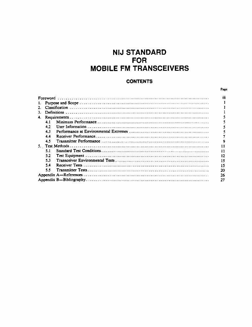
CONTENTS Page
Foreword . . . . . . . . . . . . . . . . . . . . . . . . . . . . . . . . . . . . . . . . . . . . . . . . . . . . . . . . . . . . . . . . . . . . . . . . . . . . 1 . Purposeandscope . . . . . . . . . . . . . . . . . . . . . . . . . . . . . . . . . . . . . . . . . . . . . . . . . . . . . . . . . . . . . . . . . 2 . Classification . . . . . . . . . . . . . . . . . . . . . . . . . . . . . . . . . . . . . . . . . . . . . . . . . . . . . . . . . . . . . . . . . . . . . . 3 . Definitions . . . . . . . . . . . . . . . . . . . . . . . . . . . . . . . . . . . . . . . . . . . . . . . . . . . . . . . . . . . . . . . . . . . . . . . . 4 . Requirements . . . . . . . . . . . . . . . . . . . . . . . . . . . . . . . . . . . . . . . . . . . . . . . . . . . . . . . . . . . . . . . . . . . . . .
........................................................ 4.1 Minimum Performance . . . . . . . . . . . . . . . . . . . . . . . . . . . . . . . . . . . . . . . . . . . . . . . . . . . . . . . . . . . . . 4.2 User Information
........................................ 4.3 Performance at Environmental Extremes 4.4 Receiver Performance .........................................................
...................................................... 4.5 Transmitter Performance 5 . . Test Methods ......................................................................
5.1 Standard Test Conditions ...................................................... .............................................................. 5.2 Test Equipment
............................................... 5.3 Transceiver Environmental Tests ............................................................... 5.4 Receiver Tests
5.5 Transmitter Tests ............................................................. Appendix A-References ...............................................................
.............................................................. Appendix B-Bibliography
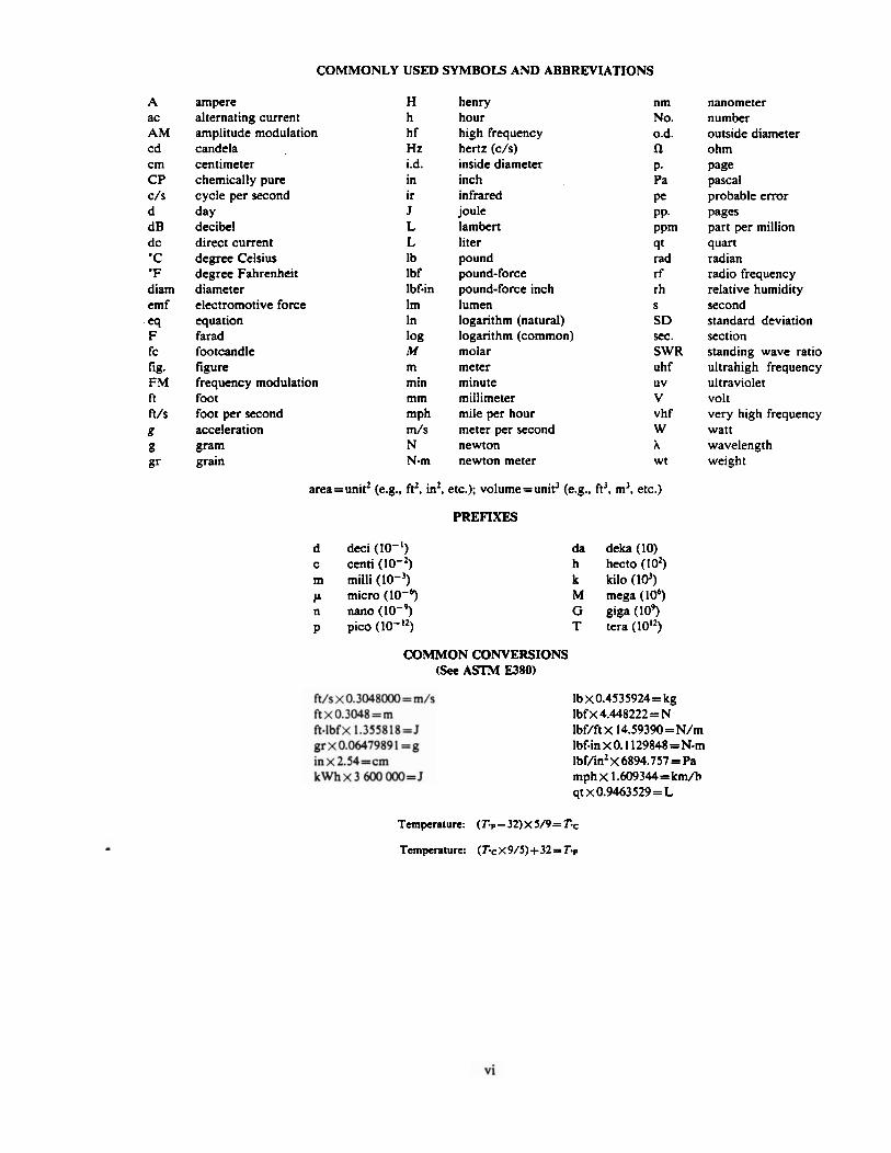
COMMONLY USED SYMBOLS AND ABBREVIATIONS
A ac AM cd cm C P c/s d dB dc ' C ' F diarn emf
-eq F fc fig. FM ft ft/s 8 8 gr
ampere alternating current amplitude modulation candela centimeter chemically pure cycle per second day decibel direct current degree Celsius degree Fahrenheit diameter electromotive force equation farad footcandle figure frequency modulation foot foot per second acceleration gram grain
H h hf Hz i.d. in ir J L L Ib Ibf Ibf-in Im In log 1u m min mm mph m/s N N-m
henry hour high frequency hertz (c/s) inside diameter inch infrared joule lambert liter pound pound-force pound-force inch lumen logarithm (natural) logarithm (common) molar meter minute millimeter mile per hour meter per second newton newton meter
nm No. 0.d. n P. Pa pe PP- PP'" 4t rad rf rh S
S D sec. SWR uhf UV
v vhf W A Wt
area=unit2 (e.g., ft2, in2, etc.); volume=unit3 (e.g.. ft', m', etc.)
PREFIXES
d deci (lo-') c centi (10-3 m milli (lo-') p micro n nano (10-4 p pic0 (lo-'')
da deka (10) h hecto (lo2) k kilo ( I d ) M mega (lo6) G gigs (104 T tera (1012)
COMMON CONVERSIONS (See ASTM E380)
lbx0.4535924= kg lbf x 4.448222 = N Ibf/ft X 14.59390=N/m Ibf-in x 0.1 129848 = N-m Ibf/in2 X 6894.757 =Pa mph x 1.609344= kmfi qt ~0.9463529 = L
nanometer number outside diameter ohm page pascal probable error Pages part per million quart radian radio frequency relative humidity second standard deviation section standing wave ratio ultrahigh frequency ultraviolet volt very high frequency watt wavelength weight
Temperature: (TF- 32) x 5/9= T.=
Temperature: (rc x 9/5)+32 = Tp
NIJ Standard-0210.00
NIJ STANDARD FOR
MOBILE FM TRANSCEIVERS
1. PURPOSE AND SCOPE
The purpose of this document is to establish performance requirements and methods of test for non- trunked. frequency modulated (FM) mobile transceivers. This standard applies to transceivers which either do not have special subsystems such as selective signaling or voice privacy, or in which such subsystems are bypassed or disabled during testing for compliance with this standard. This standard supersedes NILECJ-STD- 0202.00, Mobile FM Transmitters and NILECJ-STD-0207.00, Mobile FM Receivers.
2. CLASSIFICATION - For the purpose of this standard, mobile FM transceivers are classified by their operating frequencies.
2.1 Type I
Transceivers which operate in the 25-50 MHz band with a receiver channel spacing of 20 kHz.
2.2 Type I I
Transceivers which operate in the 150-174 MHz band with a receiver channel spacing of 30 kHz.
2.3 Type Ill
Transceivers which operate in the 400-512 MHz band with a receiver channel spacing of 25 kHz.
2.4 Type IV
Transceivers which operate in the 806-866 MHz band with a receiver channel spacing of 25 kHz.
3. DEFINITIONS
The principal terms used in this document are defined in this section. Additional definitions relating to law enforcement communications are given in LESP-RPT-0203.00, Technical Terms and Definitions Used with Law Enforcement Communications Equipment [I]'.
3.1 Adjacent-Channel Selectivity and Desensitization
The ability of a receiver to discriminate against a signal at the frequency of an adjacent channel.
Numbers in brackets ref- to references in appendix A.
3.2 AM Hum and Noise
The residual amplitude modulation present on an unmodulated carrier.
3.3 Audio Harmonic Distortion
Nonlinear distortion characterized by the appearance in the output of integral multiples of an audio- - frequency input signal.
3.4 Audio Hum and Noise Power
The average audiofrequency power dissipated in a load across the output terminals of a receiver having an unmodulated radio frequency (rf) signal input. .
3.5 Audio Noise Output Power
The average audiofrequency power dissipated in a load across the output terminals of an unsquelched receiver having no rf signal input.
3.6 Audio Output Power
The audiofrequency power dissipated in a load across the receiver output terminals of an unsquelched receiver having a modulated rf signal input.
3.7 Audio Response of a Receiver
The variation in the output of a receiver as a function of audiofrequency within a specified bandwidth.
3.8 Audio Response of a Transmitter
The degree of precision with which the frequency deviation of a transmitter responds to a designated audiofrequency signal level.
3.9 Authorized Bandwidth
The maximum width of the band of frequencies specified by the Federal Communications Commission (FCC) to be occupied by an emission, i.e., 20 kHz for public-safety agencies [2].
3.10 Carrier Attack Time
The time required for a transmitter to produce 5 0 percent of the rated camer output power after the carrier control switch is activated.
3.1 1 Carrier Output Power
For a transmitter, the rf power available at the antenna terminal when no modulating signal is present.
3.12 FM Hum and Noise
The frequency modulation present on an unmodulated carrier.
3.13 Frequency Deviation
In frequency modulation, the difference between the instantaneous frequency of the modulated carrier and the unmodulated carrier frequency.
3.14 Frequency Stability
The maximum permissible departure by the center frequency of the frequency band occupied by an - emission from the assigned frequency.

3.15 lntermodulation Attenuation
The ratio, expressed in decibels, of (1) the level of specified signals that produces an intermodulation response under specified conditions to (2) the receiver's SINAD sensitivity.
3.16 lntermodulation Response
The response resulting from the mixing of two or more frequencies, in the nonlinear elements of a receiver, in which a resultant frequency is generated that falls within the receiver pass band.
3.17 Minimum Usable Bandwidth
The frequency displacement from the unmodulated carrier frequency, + 3 kHz, of an input test signal which is 6 dB above the 12dB SINAD sensitivity voltage and which produces a l 2 d B SINAD ratio.
3.18 Modulation Limiting
That action, performed by an FM transmitter, which intentionally restricts the signal to the required spectral limits by restricting the total deviation of the emission.
3.19 Noise Quieting
The reduction of receiver audio noise output caused by the presence of an incoming rf signal.
3.20 Nominal Value
The numerical value of a device characteristic as specified by the manufacturer.
3.21 Occupied Bandwidth
The width of the frequency band containing those frequencies at which a total of 99 percent of the radiated power appears, extended to include any discrete frequency at which the power is at least 0.25 percent of the total radiated power.
3.22 Rated System Deviation
The maximum carrier frequency deviation permitted by the FCC. For law enforcement communications systems, it is f 5 kHz.
3.23 Receiver Attack Time
The time required to produce a designated audio output power level upon application of a specified rf input signal, when the squelch control is in the threshold squelch position.
3.24 Receiver Closing Time
The time required to reduce a specified audio output power to a designated level upon removal of the rf input signal, when the squelch control is in the threshold squelch position.
3.25 Sampler
A series device which couples energy over a broad frequency range from a transmission line into a third port. The attenuated output signal from the third port has the same waveform as the original signal.
3.26 Selectivity
The extent to which a receiver is capable of differentiating between the desired signal and signals at other frequencies, some of which may differ only slightly from the desired signal.
3.27 Sideband Spectrum
The emissions generated by a modulated transmitter that are within 250 percent of the authorized band- width. i.e.. +25 kHz.
3.28 SlNAD Ratio
The ratio, expressed in decibels, of (1) signal plus noise plus distortion to (2) noise plus distortion produced at the output of a receiver; from SIgnal Noise And Distortion Ratio.
3.29 SlNAD Sensitivity
The minimum modulated rf signal input level required to produce a specified SINAD ratio at a specified audio output power level.
3.30 Spurious Emission
Any part of the rf output that is not a component of the theoretical output or exceeds the authorized bandwidth.
3.31 Spurious and Harmonic Response
The output of a receiver caused by a signal at a frequency other than that to which the receiver is tuned.
3.32 Squelch
A circuit function for preventing a receiver from producing audio output power in the absence of an rf input signal.
3.33 Squelch Block
A squelched condition resulting from excessive frequency deviation due to a specified rf modulated input signal.
3.34 Standby Mode
The condition of a transceiver when it is energized but not receiving or transmitting.
3.35 Standing Wave Ratio (SWR)
The ratio of the maximum to the minimum amplitudes of the voltage or current measured along a transmission line.
3.36 Threshold Squelch Position
The adjustment of the squelch control, starting from the maximum unsquelched position, that first reduces the audio noise output power by a specified amount.
3.37 Threshold Squelch Sensitivity
The minimum modulated rf signal input level required to unsquelch a receiver when the squelch control is in the threshold squelch position.
3.38 Tight Squelch Sensitivity
The minimum modulated rf signal input level required to unsquelch a receiver when the squelch control is in the maximum squelch position.
3.39 Transceiver
The combination of radio transmitting and receiving equipment in a common housing.
4. REQUIREMENTS
4.1 Minimum Performance
The transceiver performance shall meet or exceed the requirement for each characteristic as given below and in tables 1 and 2. These performance requirements meet or exceed those given in the Rules and Regulations published by the FCC [2].
4.2 User Information
A nominal value for each of the characteristics listed in tables 1 and 2 shall be included in the information supplied to the purchaser by the manufacturer or distributor. In addition, the manufacturer shall provide the range of temperatures within which the transceiver is designed to be operated, the transmitter and receiver operating frequencies, and nominal values for transmitter carrier output power, receiver audio output imped- ance, and standard supply voltage. The manufacturer shall also indicate the magnitude of the audio input signal necessary for rated system deviation and provide sufficient audio input impedance information to enable test personnel to design an impedance matching network for use between the audio generator and transmitter audio input circuits.
4.3 Performance at Environmental Extremes
The ability of the transceiver to operate in environmental extremes shall be determined using the test methods described in section 5.3. It is suggested that these tests be performed before the transceiver is tested for compliance with the requirements of sections 4.4 and 4.5.
4.3.1 Temperature Stability
Low temperature tests shall be conducted at -30 "C (-22 'F), or the lowest temperature at which the manufacturer states that the unit will operate properly (sec. 4.2). whichever is lower. High temperature tests shall be conducted at 60 "C (140 'F) or the highest temperature at which the manufacturer states that the unit will operate properly, whichever is higher.
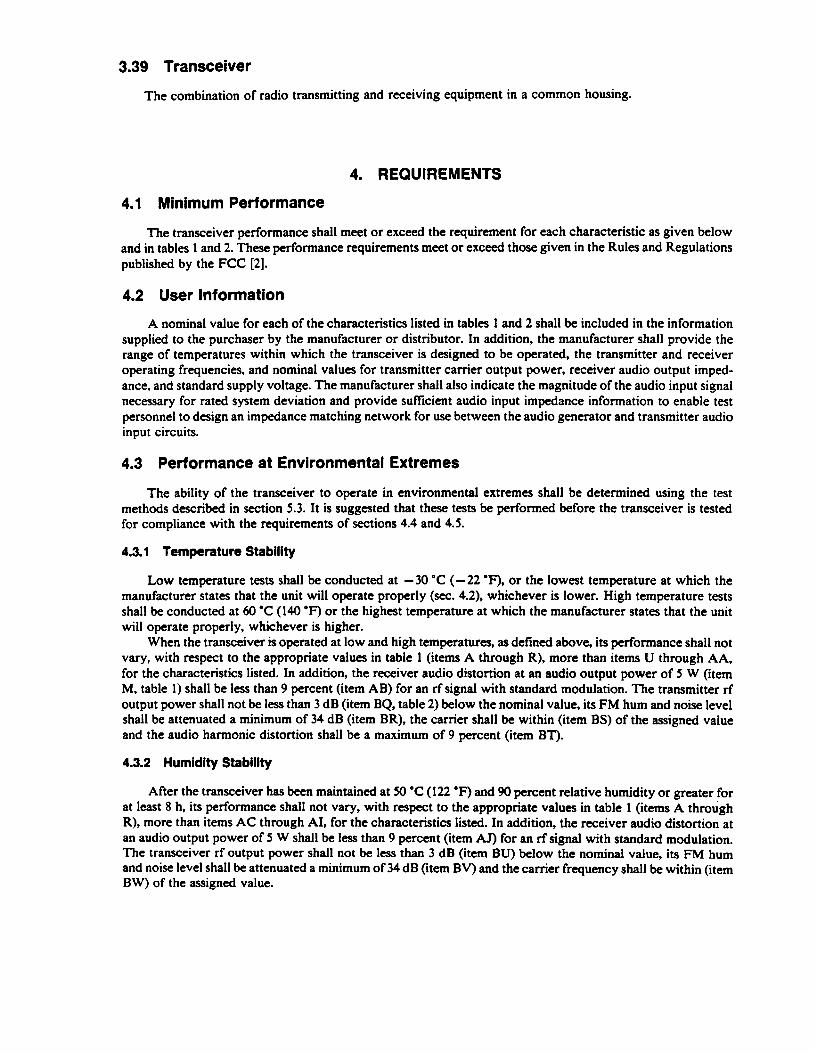
When the transceiver is operated at low and high temperatures, as defined above, its performance shall not vary, with respect to the appropriate values in table 1 (items A through R), more than items U through AA, for the characteristics listed. In addition, the receiver audio distortion at an audio output power of 5 W (item M, table 1) shall be less than 9 percent (item AB) for an rf signal with standard modulation. The transmitter rf output power shall not be less than 3 dB (item BQ, table 2) below the nominal value, its FM hum and noise level shall be attenuated a minimum of 34 dB (item BR), the carrier shall be within (item BS) of the assigned value and the audio harmonic distortion shall be a maximum of 9 percent (item BT).
4.3.2 Humidity Stability
After the transceiver has been maintained at 50 "C (122 OF) and 90 percent relative humidity or greater for at least 8 h, its performance shall not vary, with respect to the appropriate values in table 1 (items A through R), more than items AC through AI, for the characteristics listed. In addition, the receiver audio distortion at an audio output power of 5 W shall be less than 9 percent (item AJ) for an rfsignal with standard modulation. The transceiver rf output power shall not be less than 3 dB (item BU) below the nominal value, its FM hum and noise level shall be attenuated a minimum of 34 dB (item BV) and the camer frequency shall be within (item BW) of the assigned value.
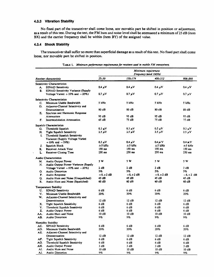
4.3.3 Vibration Stability
No fixed part of the transceiver shall come loose, nor movable part be shifted in position or adjustment, as a result of this test. During the test, the FM hum and noise level shall be attenuated a minimum of 25 dB (item BX) and the carrier frequency shall be within (item BY) of the assigned value.
4.3.4 Shock Stability
The transceiver shall suffer no more than superficial damage as a result of this test. No fixed part shall come loose, nor movable part be shifted in position.
TABLE 1. Minimum prr/mance tvquinments for reca-vets used in mobile FM tmnseeivers --
Minimum rrguinment Frequencp band (MHz)
Receiver characteristic 25-50 IS& 1 74 400-512 806866
Sensitivity Characteristics A. SINAD Sensitivity 0.4 pV 0.4 pV 0.4 pV 0.4 p V B. SINAD Sensitivity Variance (Supply
Voltage Varied + 10% and - 20%) 0.7 pV 0.7 pV 0.7 p V 0.7 pV
Selectivity Characteristics C. Minimum Usable Bandwidth 5 kHz 5 kHz 5 kHz 5 kHz D. Adjacent-Channel Selectivity and
Desensitization 80 dB 80 dB 80 dB 80 dB E. Spurious and Hannonic Response
Attenuation 95 dB 95 dB 95 dB 95 dB F. Intermodulation Attenuation 65 dB 75 dB 75 dB 75 dB
Squelch Characteristics G. Threshold Squelch H. Tight Squelch Sensitivity I. Threshold Squelch Sensitivity
Variance (Supply Voltage Varied + 10% and - 20%)
J. Squelch Block K. Receiver Attack Time L. Receiver Closing Time
0.3 pV f 5 kHz IS0 ms 250 Ills
0.4 pV f 5 kHz I S 0 ms 250 ms
0.4+ v 0.4 WV +.5 t ~ z r s k ~ z I50 rns 150 ms 250 ms 250 ms
Audio Characteristics M. Audio Output Power N. Audio Output Power Variance (Supply
Voltage Varied -+ 10% and - 20%) 0. Audio Distortion P. Audio Raporuc Q. Audio Hum and Noise (Unsquelched) R. Audio Hum and Noise (Squelched)
Tempemtun Stability U. SINAD Sensitivity V. Minimum Usable Bandwidth W. Adjacent-Channel Selectivity and
Desensitization X. Tight Squelch Sensitivity Y. Threshold Squelch Sensitivity 2. Audio Output Power
AA. Audio Hum and Noise AB. Audio Distortion
Humidity Stability AC. SINAD Sensitivity AD. Minimum Usable Bandwidth AE. Adjacent-Channel Selectivity and
Desensitization AF. Tight Squelch Sensitivity AG. Threshold Squelch Sensitivity AH. Audio Output Power AI. Audio Hum and Noise AJ. Audio Distortion

TABLE 2. Minimum per/onnance requimments for fmnrmitters used in mobile F M fmnsceiwrr
Minimum requirement Frequency band (MHz)
Tmnsmirrer chamctenstic 25-50 150-1 74 400-512 806-866
Radio Frequency Camer Characteristics BA. Carrier Output Power Variance -0.3 dB -0.3 dB -0.3 dB -0.3 dB BB. Output Power Variance (Supply
Voltage Varied + 10%) -3 dB -3dB . -3 dB -3 dB BC. Output Power Variance (Supply
Voltage Varied - 20 %) -6 dB -6 dB -6 dB -6 dB BD. Camer Frequency Tolerance 0.002% 0.0005% 0.0005% 0.00025% BE. Frequency Stability (Supply
Voltage Varied 2 15%) 0.002% 0.0005% 0.0005% 0.00025% BF. AM Hum and Noise Level 34 dB 34 dB 34 dB 34 dB BG. Carrier Attack Time 100 ms 100 ms 100 ms 100 ms
Audio Modulation Characteristics BH. Audio Hannonic Distortion 5% 5 70 5% 5% BI. FM Hum and Noise Level 40 dB 40 dB 40 dB 40 dB BJ. Audio Response + I.-3 dB + 1,-3 dB +I.-3 dB +I.-3 dB BK. Frequency Deviation 5 70 5% 5% 5% BL. Modulation Limiting f 5 kHz e 5 kHz f 5 kHz 2 5 kHz
Electromagnetic Compatibility Characteristics BM. Conducted Spurious Emissions 55 dB 55 dB 55 dB 55 dB EN. Radiated Spurious Emissions 1.65 mV/m 1.65 mV/m 16.5 mV/m 16.5 mV/m BO. Sideband Spectrum ( f 10 kHz
Frequency Separation) 25 dB 30 dB 30 dB 30 d B BP. Sideband Spectrum ( 2 2 0 kHz
Frequency Separation) 50 dB 60 dB 60 dB 60 dB
Temperature Stability BQ. Output Power -3 dB -3 dB - 3 dB -3 dB BR. FM Hum and Noise Level 34 dB 34 dB 34 dB 34 dB BS. . Carrier Frequency Tolerance 0.002% 0.0005% 0.0005% 0.00025% BT. Audio Hannonic Distortion 9% 9% 9% 9%
Humidity Stability BU. Output Power -3 dB -3 dB -3 dB -3 dB BV. FM Hum and Noise Level 34 dB 34 dB 34 dB 34 dB BW. Carrier Frequency Tolerance 0.002% 0.0005% 0.0005% 0.00025%
Vibration Stability BX. FM Hum and Noise Level 25 dB 25 dB 25 dB 25 dB BY. Carrier Frequency Tolerance 0.002% 0.0005% 0.0005% 0.00025%
4.4 Receiver Performance
4.4.1 SINAD Sensitivity
When measured in accordance with section 5.4.1, the SINAD Sensitivity of the receiver shall be 0.4 pV (item A) or less at a SINAD ratio of 12 dB and an audio output power of at least 50 percent of 5 W, i.e., 2.5 W. When the standard power supply voltage is varied + 10 percent and -20 percent, the SINAD sensitivity shall be 0.7 pV (item B) or less.
4.4.2 Selectivity Characteristics
The selectivity characteristics of minimum usable bandwidth, adjacent-channel selectivity and desensi- tization, spurious and harmonic response attenuation, and intennodulation attenuation shall be measured in accordance with section 5.4.2.

4.4.2.1 Minimum Usable Bandwidth
The minimum usable bandwidth of the receiver shall be no less than 5 kHz (item C) for an applied rf signal 6 dB above the measured 12-dB SINAD sensitivity value.
4.4.2.2 . Adjacent-Channel Selectivity and Desensitization
The adjacent-channel selectivity and desensitization of the receiver shall be 80 dB (item D) or more for a degradation of an on-channel signal from 12-dB SINAD ratio to 6-dB SINAD ratio caused by an adjacent- channel signal.
4.4.2.3 Spurious and Harmonic Response Attenuation
The spurious and harmonic response attenuation of the receiver shall be 95 dB (item E) or more as compared with the on-channel20-dB noisequieting signal voltage for receiver responses in the region between the lowest intermediate.frequency of the receiver and at least twice the receiver operating frequency, or 1000 MHz, whichever is higher.
4.4.2.4 Intermodulation Attenuation
The intermodulation attenuation of the receiver shall be (item F) or more for a degradation of an onchannel signal from 12-dB SINAD ratio to 6-dB SINAD ratio by two relatively strong signals located at one- and two-channel spacings, respectively, from the receiver frequency, both signals being at frequencies either above or below the on-channel signal.
4.4.3 Squelch Characteristics
The squelch characteristics of sensitivity, block, receiver attack time, and receiver closing time shall be measured in accordance with section 5.4.3.
4.4.3. I Squelch Sensitivity
The threshold squelch sensitivity of the receiver shall be 0.3 pV (item G) or less. The tight squelch sensitivity shall be 2.5 pV (item H) or less. When the standard power supply voltage is varied + 10 percent and -20 percent, the threshold squelch sensitivity shall be (item I) or less.
4.4.3.2 Squelch Block
The receiver shall not squelch for modulation frequencies of 0.3 to 3 kHz when the squelch control is adjusted to the maximum squelch position and the frequency deviation of the input signal is &5 kHz (item J) or less.
4.4.3.3 Receiver Attack Time
The time for the receiver to produce an audio output power of 90 percent of 5 W, i.e., 4.5 W, shall be 150 ms (item K) or less.
4.4.3.4 Receiver Closing Time
The time for the.audio output power of the receiver to decrease to 10 percent of 5 W, i.e., 0.5 W, shall be 250 ms (item L) or less.
4.4.4 Audio Characteristics
The audio characteristics of output power, distortion, response, and hum and noise shall be measured in accordance with section 5.4.4.
4.4.4.1 Audio Output Power
The audio output power of the receiver shall be at least 5 W (item M) if a loudspeaker is used at the receiver output. When the standard supply voltage is varied + 10 percent and -20 percent, the audio output power shall not be reduced more than 2 dB (item N) below 5 W.
4.4.4.2 Audio Distortion
Audio distortion of the loudspeaker at an audio output power of 5 W shall be less than 5 percent (item 0) for an rf input signal with standard modulation.
4.4.4.3 Audio Response
The audio response of the receiver, when used with a loudspeaker, shall be within -8, +2 dB (item P) of an ideal 6 dB per octave de-emphasis curve with constant frequency deviation at frequencies between 0.3 and 3 kHz, with the exception that a 6 dB per octave roll-off from 600 to 300 Hz may be present.
4.4.4.4 Audio Hum and Noise
The audio hum and noise output power from the receiver in the unsquelched condition shall be 45 dB (item Q) or more, and, in the maximum squelched condition, shall be 60 dB (item R) or more below an audio output power of 5 W.
4.5 Transmitter Performance
4.5.1 Radio Frequency Characteristics
The rf carrier characteristics of output power, frequency stability, AM hum and ,noise level, and carrier attack time shall be measured in accordance with section 5.5.1.
4.5.1.1 Output Power
Transmitter output power is specified by the FCC [2]. When the transceiver is in the transmit mode, the carrier output power delivered to a standard output load shall not decrease more than 0.3 dB (item BA) from the nominal value at any time during the standard test duty cycle, except for the initial second after the transceiver has been switched from the standby mode to the transmit mode. When the standard supply voltage is varied 2 10 percent, the output power shall not decrease by more than 3 dB (item BB). When the standard supply voltage is reduced by 20 percent, the output power shall not decrease by more than 6 dB (item BC).
4.5.1.2 Frequency Stability
The carrier frequency shall be within (item BD) of the assigned value at all times during the standard test duty cycle that the transceiver is in the transmit mode, except for the initial second after the transceiver has been switched from the standby mode to the transmit mode. When the standard supply voltage is varied f 15 percent, the carrier frequency shall be maintained within (item BE) of the assigned value.
4.5.1.3 AM Hum and No& Level
The-AM hum and noise level shall be attenuated a minimum of 34 dB (item BF) below the unmodulated nominal carrier output power level.
4.5.1.4 Carrier Attack Time
The carrier output power shall increase to 5 0 percent of its nominal value in less than 100 ms (item BG).
4.5.2 Audio Modulation Characteristics
The audio modulation characteristics of harmonic distortion, FM hum and noise level, response, frequency deviation, and modulation limiting shall be measured in accordance with section 5.5.2.
4.5.2.1 Audio Harmonic Distortion
The audio harmonic distortion shall be a maximum of 5 percent (item BH).
4.5.2.2 FM Hum and Noise Level
The FM hum and noise level shall be attenuated a minimum of 40 dB (item BI).
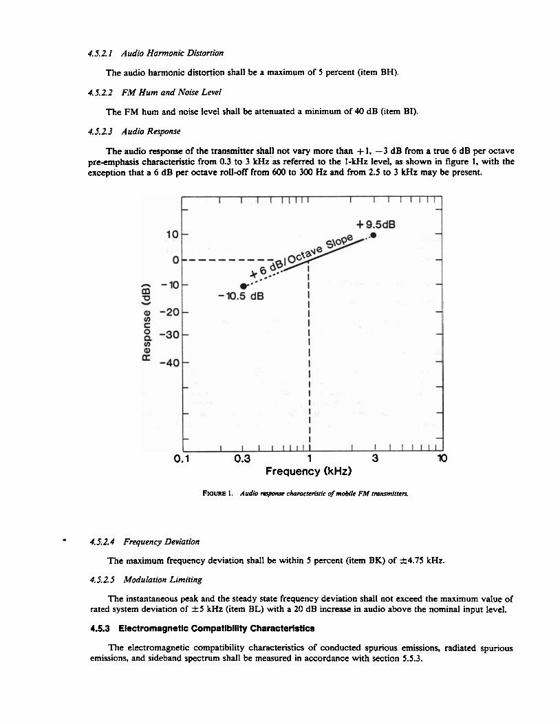
4.5.2.3 Audio Response
The audio response of the transmitter shall not vary more than + 1, -3 dB from a true 6 dB per octave pre-emphasis characteristic from 0.3 to 3 kHz'as referred to the I-kHz level, as shown in figure 1, with the exception that a 6 dB per octave rolloff from 600 to 300 Hz and from 2.5 to 3 kHz may be present.
Frequency (kHz)
F~ouue I . Audio mponse ckamcccrisrIe of mobile FM tmnsmirrem
4.5.2.4 Frequency Deviation
The maximum frequency deviation shall be within 5 percent (item BK) of k4.75 kHz.
4.5.2.5 Modulation Limitittg
The instantaneous peak and the steady state frequency deviation shall not exceed the maximum value of rated system deviation of f 5 kHz (item BL) with a 20 dB increase in audio above the nominal input level.
4.5.3 Electromagnetic Compatibility Characteristics
The electromagnetic compatibility characteristics of conducted spurious emissions, radiated spurious emissions, and sideband spectrum shall be measured in accordance with section 5.5.3.
4.5.3. I Conducted Spurious Emissions
Each conducted spurious emission shall be attenuated a minimum of [55 (item BM) + 10 log,,, (output power in watts)] dB below the level of the transmitter output power.
4.5.3.2 Radiated Spurious Emissions
Each radiated spurious emission shall be no larger than 1.65 mV/m (item BN) at 30 m for type I and I1 transceivers. or 16.5 mV/m (item BN) at 3 m for type 111 and IV transceivers; i.e., each radiated spurious emission shall be less than 50 pW.
4.5.3.3 Sideband Spectrum
Each spurious sideband emission shall be attenuated greater than (item BO) when the frequency is separated from the assigned camer by + l o kHz, and shall be attenuated greater than (item BP) when the frequency is separated from the assigned carrier by +20 kHz.
5. TEST METHODS
5.1 Standard Test Conditions
Allow all measurement equipment to warm up until the system has achieved sufficient stability to perform the measurement. Unless otherwise specified, perform all measurements under standard test conditions.
5.1.1 Standard Temperature
Standard ambient temperature shall be between 20 and 30 "C (68 and 86 OF).
5.1.2 Standard Relative Humidity
Standard ambient relative humidity shall be between 10 and 85 percent.
5.1.3 Standard Supply Voltage
In a nominal 12-V dc system, the standard supply voltage shall be determined from the equation V = 13.8 -(0.02)1, where I is the current (in amperes) delivered to the mobile unit. For example, if the current while transmitting is 12 A, the standard supply voltage should be approximately 13.6 V. Appropriate factors shall be used for other voltage supply systems. A well - filtered electronic power source should be used in place of a battery for safety and convenience. The standard supply voltage shall be applied to the input terminals of the dc supply cables (including all connectors and circuit protectors) furnished by the manufacturer and adjusted to within 1 percent of the value calculated above.
5.1.4 Standard Test Frequencies
The standard test frequencies shall be the transmitter and the receiver operating frequencies.
5.1.5 Standard Test Modulation
5. I. 5. I Audio Test Modulation
Audio test modulation shall be a 1-kHz signal (from a source with distortion less than 1%) at the level required to produce 60 percent of rated system deviation (i.e.. k 3 kHz).
5.1.5.2 Electromagnetic Compatibility Test Modulation
Electromagnetic compatibility test modulation shall be a 2.5 kHz sine wave at an input level 16 dB greater than that required to produce 50 percent of rated system deviation at 1 kHz.
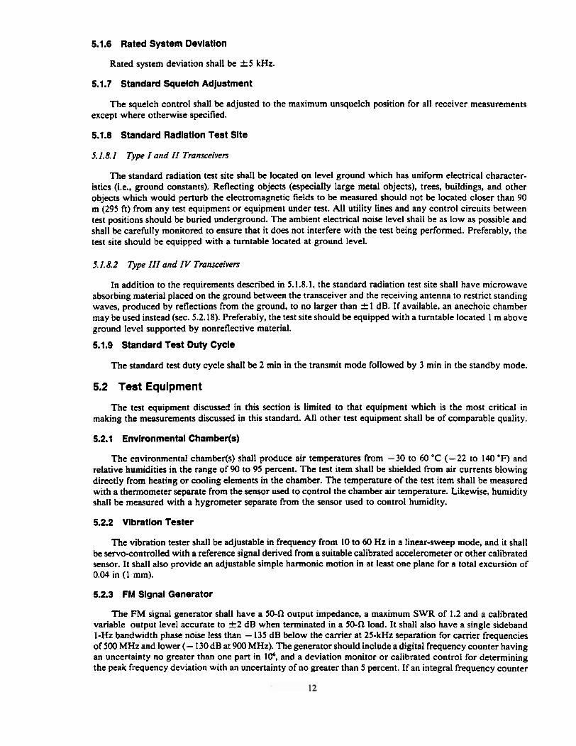
5.1.6 Rated System Deviation
Rated system deviation shall be f 5 kHz.
5.1.7 Standard Squelch Adjustment
The squelch control shall be adjusted to the maximum unsquelch position for all receiver measurements except where otherwise specified.
5.1.8 Standard Radiation Test Site
5.1.8.2 Type I and II Transceivers
The standard radiation test site shall be located on level ground which has uniform electrical character- istics (i.e., ground constants). Reflecting objects (especially large metal objects), trees, buildings, and other objects which would perturb the electromagnetic fields to be measured should not be located closer than 90 m (295 ft) from any test equipment or equipment under test. All utility lines and any control circuits between test positions should be buried underground. The ambient electrical noise level shall be as low as possible and shall be carefully monitored to ensure that it does not interfere with the test being performed. Preferably, the test site should be equipped with a turntable located at ground level.
5.1.8.2 Type III and IV Transceivers
In addition to the requirements described in 5.1.8.1, the standard radiation test site shall have microwave absorbing material placed on the ground between the transceiver and the receiving antenna to restrict standing waves, produced by reflections from the ground, to no larger than f 1 dB. If available, an anechoic chamber may be used instead (sec. 5.2.18). Preferably, the test site should be equipped with a turntable located 1 m above ground level supported by nonreflective material.
5.1.9 Standard Test Duty Cycle
The standard test duty cycle shall be 2 min in the transmit mode followed by 3 min in the standby mode.
5.2 Test Equipment
The test equipment discussed in this section is limited to that equipment which is the most critical in making the measurements discussed in this standard. All other test equipment shall be of comparable quality.
5.2.1 Environmental Chamber@)
The environmental chamber(s) shall produce air temperatures from -30 to 60 "C (-22 to 140 OF) and relative humidities in the range of 90 to 95 percent. The test item shall be shielded from air currents blowing directly from heating or cooling elements in the chamber. The temperature of the test item shall be measured with a thermometer separate from the sensor used to control the chamber air temperature. Likewise, humidity shall be measured with a hygrometer separate from the sensor used to control humidity.
5.2.2 Vibration Tester
The vibration tester shall be adjustable in frequency from 10 to 60 Hz in a linear-sweep mode, and it shall be servo-controlled with a reference signal derived from a suitable calibrated accelerometer or other calibrated sensor. It shall also provide an adjustable simple harmonic motion in at least one plane for a total excursion of 0.04 in (1 mm).
5.2.3 FM Signal Generator
The FM signal generator shall have a 50-f2 output impedance, a maximum SWR of 1.2 and a calibrated variable output level accurate to f 2 dB when terminated in a 50-fl load. It shall also have a single sideband I-Hz bandwidth phase noise less than - 135 dB below the carrier at 25-kHz separation for camer frequencies of 500 MHz and lower (- 130 dB at 900 MHz). The generator should include a digital frequency counter having an uncertainty no greater than one part in lo6, and a deviation monitor or calibrated control for determining the peak frequency deviation with an uncertainty of no greater than 5 percent. If an integral frequency counter
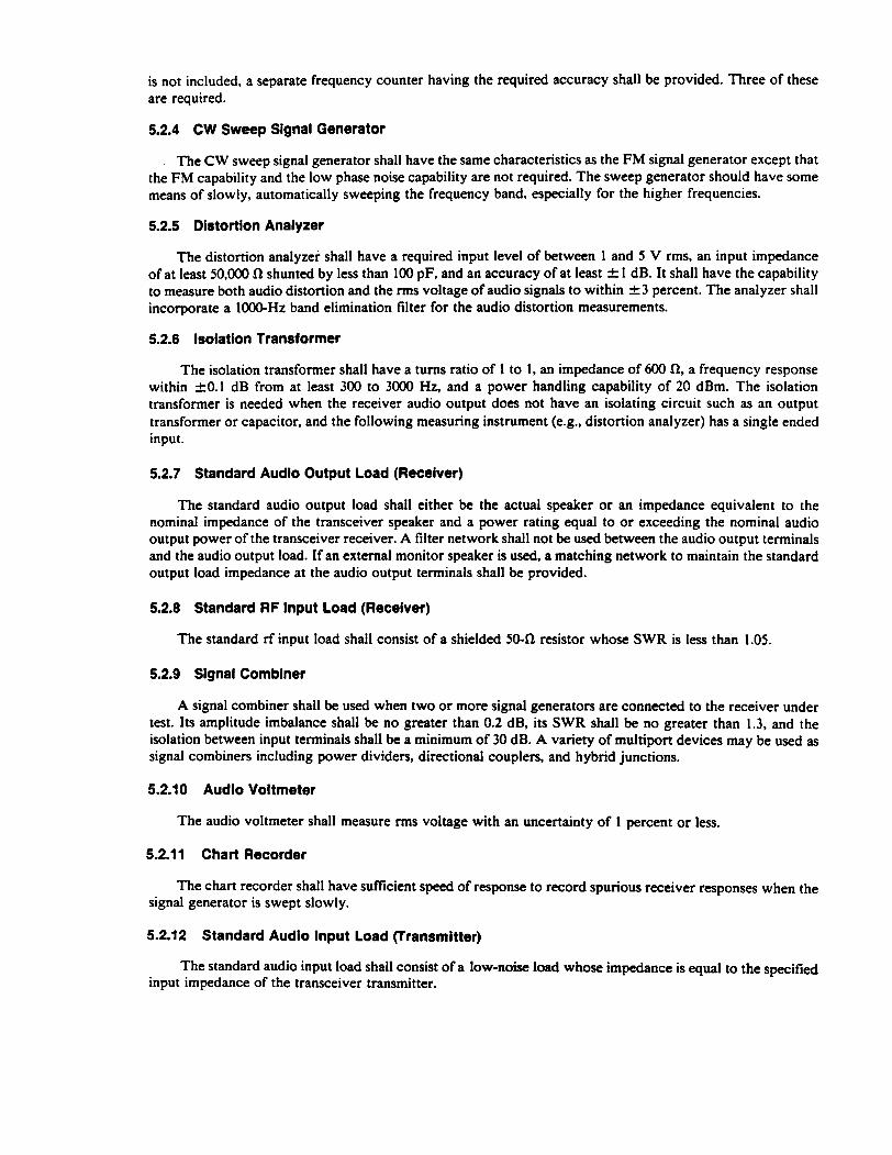
is not included, a separate frequency counter having the required accuracy shall be provided. Three of these are required.
5.2.4 CW Sweep Signal Generator
The C W sweep signal generator shall have the same characteristics as the FM signal generator except that the FM capability and the low phase noise capability are not required. The sweep generator should have some means of slowly, automatically sweeping the frequency band, especially for the higher frequencies.
5.2.5 Distortion Analyzer
The distortion analyzer shall have a required input level of between 1 and 5 V rms, an input impedance of at least 50,000 R shunted by less than 100 pF, and an accuracy of at least f 1 dB. It shall have the capability to measure both audio distortion and the rms voltage of audio signals to within f 3 percent. The analyzer shall incorporate a 1000-Hz band elimination filter for the audio distortion measurements.
5.2.6 Isolation Transformer
The isolation transformer shall have a turns ratio of 1 to 1, an impedance of 600 R, a frequency response within 20.1 dB from at least 300 to 3000 Hz, and a power handling capability of 20 dBm. The isolation transformer is needed when the receiver audio output does not have an isolating circuit such as an output transformer or capacitor, and the following measuring instrument (e.g., distortion analyzer) has a single ended input.
5.2.7 Standard Audio Output Load (Receiver)
The standard audio output load shall either be the actual speaker or an impedance equivalent to the nominal impedance of the transceiver speaker and a power rating equal to or exceeding the nominal audio output power of the transceiver receiver. A filter network shall not be used between the audio output terminals and the audio output load. If an external monitor speaker is used, a matching network to maintain the standard output load impedance at the audio output terminals shall be provided.
5.2.8 Standard RF lnput Load (Receiver)
The standard rf input load shall consist of a shielded 50-R resistor whose SWR is less than 1.05.
5.2.9 Signal Combiner
A signal combiner shall be used when two or more signal generators are connected to the receiver under test. Its amplitude imbalance shall be no greater than 0.2 dB, its SWR shall be no greater than 1.3, and the isolation between input terminals shall be a minimum of 30 dB. A variety of multiport devices may be used as signal combiners including power dividers, directional couplers, and hybrid junctions.
5.2.10 Audio Voltmeter
The audio voltmeter shall measure rms voltage with an uncertainty of 1 percent or less.
5.2.1 1 Chart Recorder
The chart recorder shall have sufficient speed of response to record spurious receiver responses when the signal generator is swept slowly.
5.2.12 Standard Audio lnput Load (Transmitter)
The standard audio input load shall consist of a low-noise load whose impedance is equal to the specified input impedance of the transceiver transmitter.
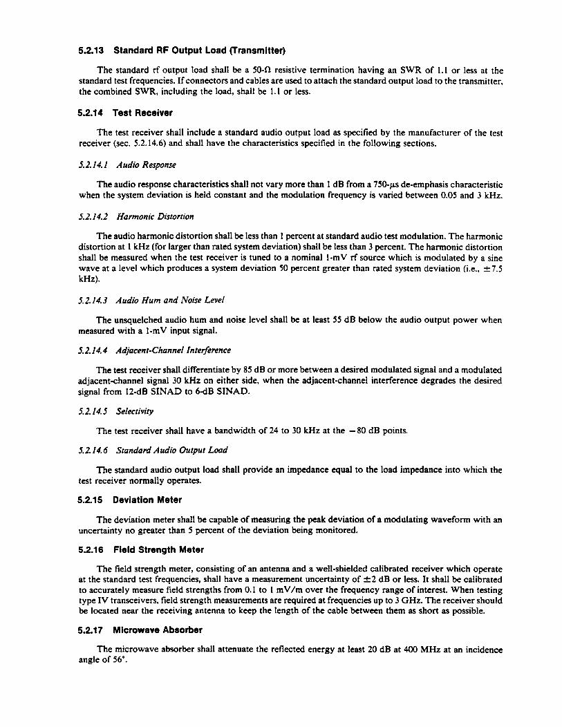
52.13 Standard R F Output Load (Transmitter)
The standard rf output load shall be a 50-R resistive termination having an SWR of 1.1 or less at the standard test frequencies. If connectors and cables are used to attach the standard output load to the transmitter, the combined SWR, including the load, shall be 1.1 or less.
5.2.14 Test Receiver
The test receiver shall include a standard audio output load as specified by the manufacturer of the test receiver (sec. 5.2.14.6) and shall have the characteristics specified in the following sections.
5.2.14.1 Audio Response
The audio response characteristics shall not vary more than 1 dB from a 750-p de-emphasis characteristic when the system deviation is held constant and the modulation frequency is varied between 0.05 and 3 kHz.
5.2.14.2 Harmonic Distortion
The audio harmonic distortion shall be less than 1 percent at standard audio test modulation. The harmonic distortion at 1 kHz (for larger than rated system deviation) shall be less than 3 percent. The harmonic distortion shall be measured when the test receiver is tuned to a nominal I-mV rf source which is modulated by a sine wave at a level which produces a system deviation 50 percent greater than rated system deviation (i.e., k7.5 kHz).
12.14.3 Audio Hum and Noise Level
The unsquelched audio hum and noise level shall be at least 55 dB below the audio output power when measured with a 1-mV input signal.
5.2.14.4 Adjrrcent-Channel Interference
The test receiver shall differentiate by 85 dB or more between a desired modulated signal and a modulated adjacent-channel signal 30 kHz on either side, when the adjacent-channel interference degrades the desired signal from 12-dB SINAD to 6-dB SINAD.
5.2.14.5 Selectivity
The test receiver shall have a bandwidth of 24 to 30 kHz at the -80 dB points.
5.2.14.6 Standard Audio Output Load
The standard audio output load shall provide an impedance equal to the load impedance into which the test receiver normally operates.
5.2.15 Deviation Meter
The deviation meter shall be capable of measuring the peak deviation of a modulating waveform with an uncertainty no greater than 5 percent of the deviation being monitored.
5.2.16 Field Strength Meter
The field strength meter, consisting of an antenna and a well-shielded calibrated receiver which operate at the standard test frequencies, shall have a measurement uncertainty of f 2 dB or less. It shall be calibrated to accurately measure field strengths from 0.1 to 1 mV/m over the frequency range of interest. When testing type IV transceivers, field strength measurements are required at frequencies up to 3 GHz. The receiver should be located near the receiving antenna to keep the length of the cable between them as short as possible.
5.2.1 7 Microwave Absorber
The microwave absorber shall attenuate the reflected energy at least 20 dB at 400 MHz at an incidence angle of 56".
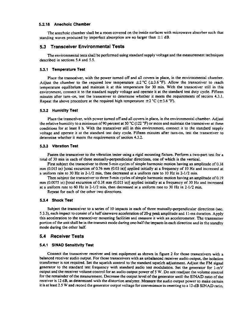
5.2.18 Anechoic Chamber
The anechoic chamber shall be a room covered on the inside surfaces with microwave absorber such that standing waves produced by imperfect absorption are no larger than f 1 dB.
5.3 Transceiver Environmental Tests
The environmental tests shall be performed using standard supply voltage and the measurement techniques described in sections 5.4 and 5.5.
5.3.1 Temperature Test
Place the transceiver, with the power turned off and all covers in place, in the environmental chamber. Adjust the chamber to the required low temperature +2 'C (k3.6 OF). Allow the transceiver to reach temperature equilibrium and maintain it at this temperature for 30 min. With the transceiver still in this environment, connect it to the standard supply voltage and operate it at the standard test duty cycle. Fifteen minutes after turn-on, test the transceiver to determine whether it meets the requirements of section 4.3.1. Repeat the above procedure at the required high temperature A2 'C (k3.6 OF).
5.3.2 Humidity Test
Place the transceiver, with power turned off and all covers in place. in the environmental chamber. Adjust the relative humidity to a minimum of 90 percent at 50 "C (122 OF) or more and maintain the transceiver at these conditions for at least 8 h. With the transceiver still in this environment, connect it to the standard supply voltage and operate it at the standard test duty cycle. Fifteen minutes after turn-on, test the transceiver to determine whether it meets the requirements of section 4.3.2.
5.3.3 Vibration Test
Fasten the transceiver to the vibration tester using a rigid mounting fixture. Perform a two-part test for a total of 30 min in each of three mutually-perpendicular directions, one of which is the vertical.
First subject the transceiver to three 5-min cycles of simple harmonic motion having an amplitude of 0.38 mm (0.015 in) [total excursion of 0.76 mm (0.03 in)] applied initially at a frequency of 10 Hz and increased at a uniform rite to 30 Hz in 2-1/2 min, then decreased at a uniform rate to 10 Hz in 2-1/2 min.
Then subject the transceiver to three 5-min cycles of simple harmonic motion having an amplitude of 0.19 mm (0.0075 in) [total excursion of 0.38 mm (0.015 in)] applied initially at a frequency of 30 Hz and increased at a uniform rate to 60 Hz in 2-1/2 min, then decreased at a uniform rate to 30 Hz in 2-1/2 min.
Repeat for each of the other two directions.
5.3.4 Shock Test
Subject the transceiver to a series of 10 impacts in each of three mutually-perpendicular directions (sec. 5.3.3), each impact to consist of a half sinewave acceleration of 20-g peak amplitude and 1 1-ms duration. Apply this acceleration to the transceiver mounting facilities and measure it with an accelerometer. The transmitter portion of the unit shall be in the transmit mode during one-half the impacts in each direction and in the standby mode during the other half.
5.4 Receiver Tests
5.4.1 SlNAD Sensitivity Test
Connect the transceiver receiver and test equipment as shown in figure 2 for those transceivers with a balanced receiver audio output. For those transceivers with an unbalanced receiver audio output, the isolation transformer is not required. Set the squelch control to the standard squelch adjustment. Adjust the FM signal generator to the standard test frequency with standard audio test modulation. Set the generator for 1-mV output and the receiver volume control for an audio output power of 5 W. Do not readjust the volume control for the remainder of the measurement. Decrease the output level of the generator until the SINAD ratio of the receiver is 12 dB, as determined with the distortion analyzer. Measure the audio output power to make certain it is at least 2.5 W and record the generator output voltage for convenience in resetting to a 12-dB SINAD ratio,
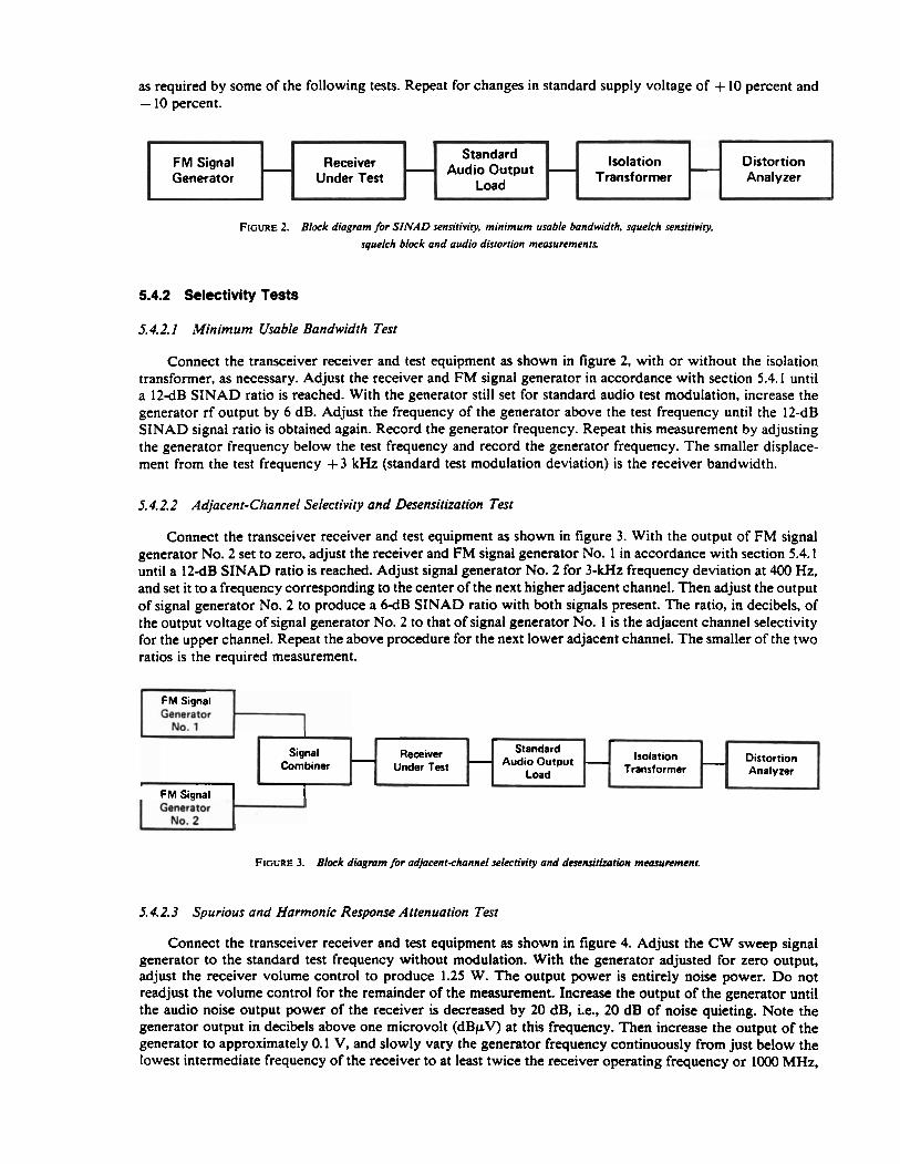
as required by some of the following tests. Repeat for changes in standard supply voltage of + 10 percent and - 10 percent.
FIGURE 2. Block diagram for SINAD sensiriviry. minimum usable bandwidth. squelch sensitivity,
squelch block and audio distortion measurcmenrs.
5.4.2 Selectivity Tests
5.4.2. I Minimum Usable Bandwidth Test
Isolation Transformer
Connect the transceiver receiver and test equipment as shown in figure 2, with or without the isolation transformer, as necessary. Adjust the receiver and FM signal generator in accordance with section 5.4.1 until a 12-dB SINAD ratio is reached. With the generator still set for standard audio test modulation, increase the generator rf output by 6 dB. Adjust the frequency of the generator above the test frequency until the 12-dB SINAD signal ratio is obtained again. Record the generator frequency. Repeat this measurement by adjusting the generator frequency below the test frequency and record the generator frequency. The smaller displace- ment from the test frequency + 3 kHz (standard test modulation deviation) is the receiver bandwidth.
Distortion Analyzer
Receiver Under Ted
FM Signal Generator
- Standard Audio Output
Load
5.4.2.2 Adjacen t-Channel Selectivity and Desensitization Test
- -
Connect the transceiver receiver and test equipment as shown in figure 3. With the output of FM signal generator No. 2 set to zero, adjust the receiver and FM signal generator No. 1 in accordance with section 5.4.1 until a 12-dB SINAD ratio is reached. Adjust signal generator No. 2 for 3-kHz frequency deviation at 400 Hz. and set it to a frequency corresponding to the center of the next higher adjacent channel. Then adjust the output of signal generator No. 2 to produce a 6 d B SINAD ratio with both signals present. The ratio, in decibels, of the output voltage of signal generator No. 2 to that of signal generator No. 1 is the adjacent channel selectivity for the upper channel. Repeat the above procedure for the next lower adjacent channel. The smaller of the two ratios is the required measurement.
Generator
Generator 1
No. 2
I
FIGURE 3. Block diagmm for ad@cent-channd selectivity and d e . s e ~ ~ ~ l ~ ~ ~ mcozun-menr.
5.4.2.3 Spurious and Harmonic Response Attenuation Test
I
Signal Combiner -
Connect the transceiver receiver and test equipment as shown in figure 4. Adjust the CW sweep signal generator to the standard test frequency without modulation. With the generator adjusted for zero output, adjust the receiver volume control to produce 1.25 W. The output power is entirely noise power. Do not readjust the volume control for the remainder of the measurement. Increase the output of the generator until the audio noise output power of the receiver is decreased by 20 dB, i.e., 20 dB of noise quieting. Note the generator output in decibels above one microvolt (dBpV) at this frequency. Then increase the output of the generator to approximately 0.1 V, and slowly vary the generator frequency continuously from just below the lowest intermediate frequency of the receiver to at least twice the receiver operating frequency or 1000 MHz,
- Receiver
Under let -
I .
Isolation Transformer
Standard Audio Output
Load . - - Distortion
Analyzer
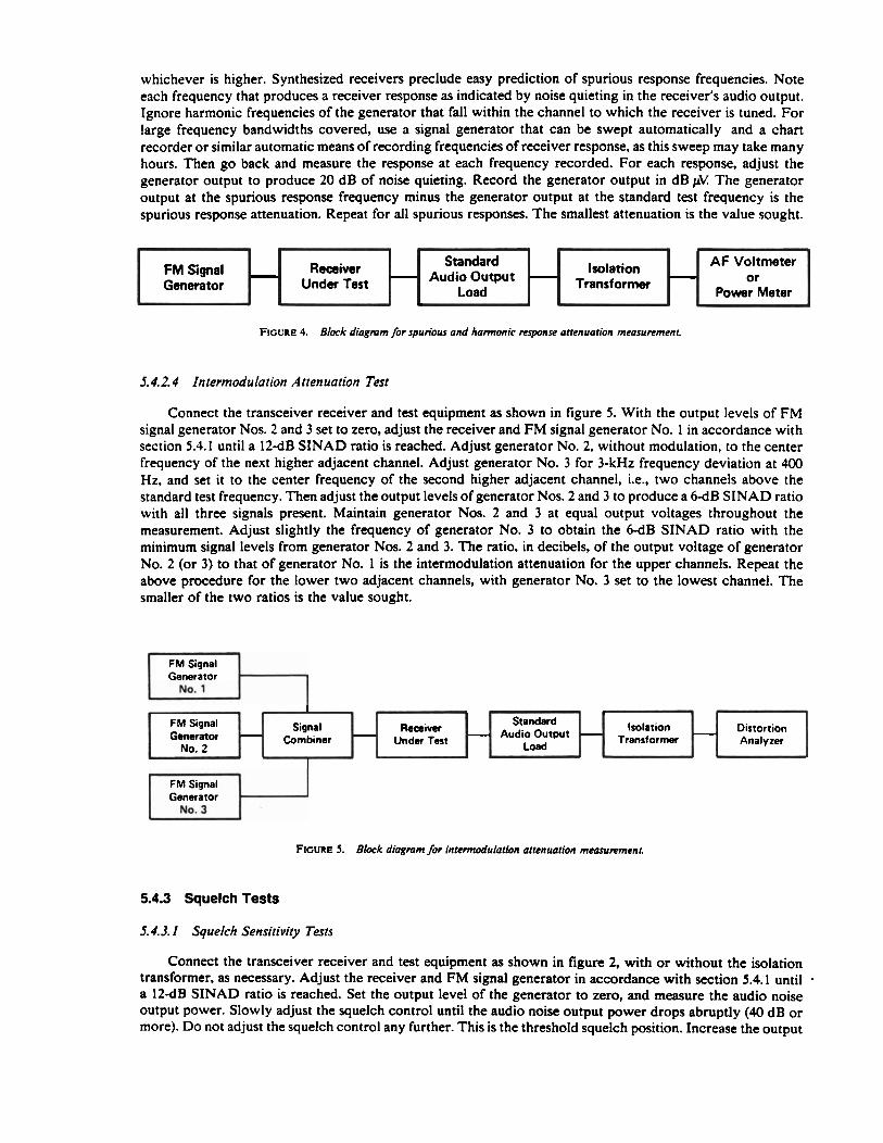
whichever is higher. Synthesized receivers preclude easy prediction of spurious response frequencies. Note each frequency that produces a receiver response as indicated by noise quieting in the receiver's audio output. Ignore harmonic frequencies of the generator that fall within the channel to which the receiver is tuned. For large frequency bandwidths covered, use a signal generator that can be swept automatically and a chart recorder or similar automatic means of recording frequencies of receiver response, as this sweep may take many hours. Then go back and measure the response at each frequency recorded. For each response, adjust the generator output to produce 20 dB of noise quieting. Record the generator output in dB pV: The generator output at the spurious response frequency minus the generator output at the standard test frequency is the spurious response attenuation. Repeat for all spurious responses. The smallest attenuation is the value sought.
FIGURE 4. Block diagmm /or spurious and harmonic response attenuation measurement.
5.4.2.4 Intermodulation Attenuation Test
FM Signal Generator
Connect the transceiver receiver and test equipment as shown in figure 5. With the output levels of FM signal generator Nos. 2 and 3 set to zero, adjust the receiver and FM signal generator No. 1 in accordance with section 5.4.1 until a 12-dB SINAD ratio is reached. Adjust generator No. 2, without modulation, to the center frequency of the next higher adjacent channel. Adjust generator No. 3 for 3-kHz frequency deviation at 400 Hz, and set it to the center frequency of the second higher adjacent channel, i.e., two channels above the standard test frequency. Then adjust the output levels of generator Nos. 2 and 3 to produce a 6-dB SINAD ratio with all three signals present. Maintain generator Nos. 2 and 3 at equal output voltages throughout the measurement. Adjust slightly the frequency of generator No. 3 to obtain the 6-dB SINAD ratio with the minimum signal levels from generator Nos. 2 and 3. The ratio, in decibels, of the output voltage of generator No. 2 (or 3) to that of generator No. 1 is the intermodulation attenuation for the upper channels. Repeat the above procedure for the lower two adjacent channels, with generator No. 3 set to the lowest channel. The smaller of the two ratios is the value sought.
-
1 FM Signal 1
Receiver Under Test
FM Signal Signal Generator F,.....I.;..~.
- AF Voltmeter or
Power Meter
Isolation Transformer
FM Signal Generator
-
FIGURE 5. Block diagmm /or intermodulation attenuation measunment.
Standard Audio Output
Load .
Receiver -...w...~. Undw Test
5.4.3 Squelch Tests
-
Standard Audio Output
Load -
5.4.3. I Squelch Sensitivity Tests
Connect the transceiver receiver and test equipment as shown in figure 2, with or without the isolation transformer, as necessary. Adjust the receiver and FM signal generator in accordance with section 5.4.1 until - a 12-dB SINAD ratio is reached. Set the output level of the generator to zero, and measure the audio noise output power. Slowly adjust the squelch control until the audio noise output power drops abruptly (40 dB or more). Do not adjust the squelch control any further. This is the threshold squelch position. Increase the output
- Isolation Transformer
- Distortion Analyzer

level of the signal generator until the measured audio output power is within 10 dB of 5 W. The signal generator output voltage is the value for threshold squelch sensitivity. Repeat for changes in standard supply voltage of + 10 percent and -20 percent.
Repeat the above procedure with the squelch control in the maximum squelch position. The resultant signal generator output voltage is the value for tight squelch sensitivity.
5.4.3.2 Squelch Block Test
Connect the transceiver receiver and test equipment as shown in figure 2, with or without the isolation transformer, as necessary. Adjust the receiver and FM signal generator in accordance with section 5.4.1 to give 5 W of audio output power. Set the output level of the signal generator to zero, and measure the audio noise output power. Then set the squelch control to the maximum squelch position. Adjust the output level of the generator to 12 dB above the measured value of the receiver's tight squelch sensitivity voltage. Then increase the frequency deviation of the generator until the audio output power drops abruptly (40 dB or more). Repeat the above procedure with modulation frequencies of 0.3,0.5.2.5, and 3 kHz. The frequency deviations of the signal generator nloduIation are the values for squelch block.
5.4.3.3 Receiver Attack Time Test
Connect the equipment as shown in figure 6a. Open and close the SPST switch to trigger the oscilloscope trace. Connect the dc output of the coaxial diode detector to the vertical input of the oscilloscope and adjust the horizontal centering controls so that the start of the detector output begins at the left graticule of the oscilloscope screen. Do not adjust the oscilloscope trigger or centering controls any further.
FIGURE 6a. Black diagmm /Or setting oscilloseopc rrigger.
Standard RF lnput Load
Connect the transceiver receiver and test equipment as shown in figure 6b. With the SPST switch closed, adjust the FM signal generator in accordance with section 5.4.1 until a 12-dB SINAD ratio is reached. Set the signal generator to zero, and measure the audio noise output power. Slowly adjust the squelch control until the audio output power drops abruptly (40 dB or more). Do not adjust the squelch any further. Adjust the generator output level to 12 dB above the'measured value of the receiver threshold squelch sensitivity voltage. With the oscilloscope on recurrent sweep, adjust the oscilloscope vertical controls for full-scale deflection. D o not adjust the trigger. Return the oscilloscope to external trigger and open and then close the SPST switch and photograph the trace. The time required for the sweep to travel from the left side of the oscilloscope graticule until the audio output power level reaches 4.5 W is the value of receiver attack time.
Coaxial
5.4.3.4 Receiver Closing Time Test
Connect the equipment as shown in figure 6a. Adjust the oscilloscope so the output from the coaxial diode detector stops at the left graticule of the oscilloscope when the SPST switch is opened. Connect the receiver and test equipment as shown in figure 6b. Adjust all equipment as in section 5.4.3.3. Open the SPST switch and photograph the display. The time required for the sweep to travel from the left graticule of the oscilloscope until the audio output power level falls to 500 mW is the value of receiver closing time.
Diode Detector
FM Signal Generator
Oscilloscope
0 Vertical lnput
0 Trigger lnput
I
I DC Power
Supply o b SPST
A
1 Switch I
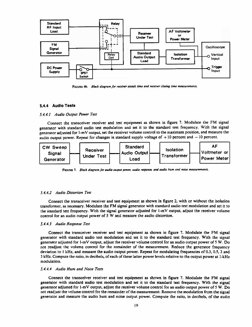
FIGURE 6b. Block diagmm for receiver attack time and receiver closing time mranrremenrr
Standard RF lnput
5.4.4 Audio Tests
5.4.4.1 Audio Output Power Test
AF Voltmeter or
Load
Connect the transceiver receiver and test equipment as shown in figure 7. Modulate the FM signal generator with standard audio test modulation and set it to the standard test frequency. With the signal generator adjusted for I-mV output, set the receiver volume control to the maximum position, and measure the audio output power. Repeat for changes in standard supply voltage of + 10 percent and - 10 percent.
Receiver Under Test
*I
FIGURE 7. Block diagmm for audio output porn audio response. and audio hum and mix mranrrements.
Power Meter
5.4.4.2 Audio Distortion Test
AF Voltmeter or Power Meter
Connect the transceiver receiver and test equipment as shown in figure 2, with or without the isolation transformer, as necessary. Modulate the FM signal generator with standard audio test modulation and set it to the standard test frequency. With the signal generator adjusted for 1-mV output, adjust the receiver volume control for an audio output power of 5 W and measure the audio distortion.
F M I - Signal I Oscilloscope
-
5.4.4.3 Audio Response Test
Connect the transceiver receiver and test equipment as shown in figure 7. Modulate the FM signal generator with standard audio test modulation and set it to the standard test frequency. With the signal generator adjusted for I-mV output, adjust the receiver volume control for an audio output power of 5 W. Do not readjust the volume control for the remainder of the measurement. Reduce the generator frequency deviation to 1 kHz, and measure the audio output power. Repeat for modulating frequencies of 0.3.0.5.2 and 3 kHz. Compute the ratio, in decibels, of each of these latter power levels relative to the output power at I-kHz modulation.
Isolation Vertical ~ ~ ~ ~ , f Input
- Receiver Under Test
CW Sweep Signal
Generator
5.4.4.4 Audio Hum and Noise Tests
DC Power 1 Trigger - SUPP~Y
J w SPST
O Input
swnth u - Generator .
1
-
Connect the transceiver receiver and test equipment as shown in figure 7. Modulate the FM signal generator with standard audio test modulation and set it to the standard test frequency. With the signal generator adjusted for 1-mV output, adjust the receiver volume control for an audio output power of 5 W. D o not readjust the volume control for the remainder of the measurement. Remove the modulation from the signal generator and measure the audio hum and noise output power. Compute the ratio, in decibels, of the audio
Standard Audio Output
Load
Isolation Transformer
4
Standard Audio Output
Load
-
output power to the audio hum and noise output power. This is the value for audio hum and noise (unsquelc hed).
Set the squelch control to its maximum squelch position. Set the output level of the generator to zero and measure the audio hum and noise output power. Calculate the ratio in decibels of the audio output power to the audio hum and noise output power. This is the value for audio hum and noise (squelched).
5.5 Transmitter tests
5.5.1 Radio Frequency Carrier Tests
5.5. I. I Output Power Test
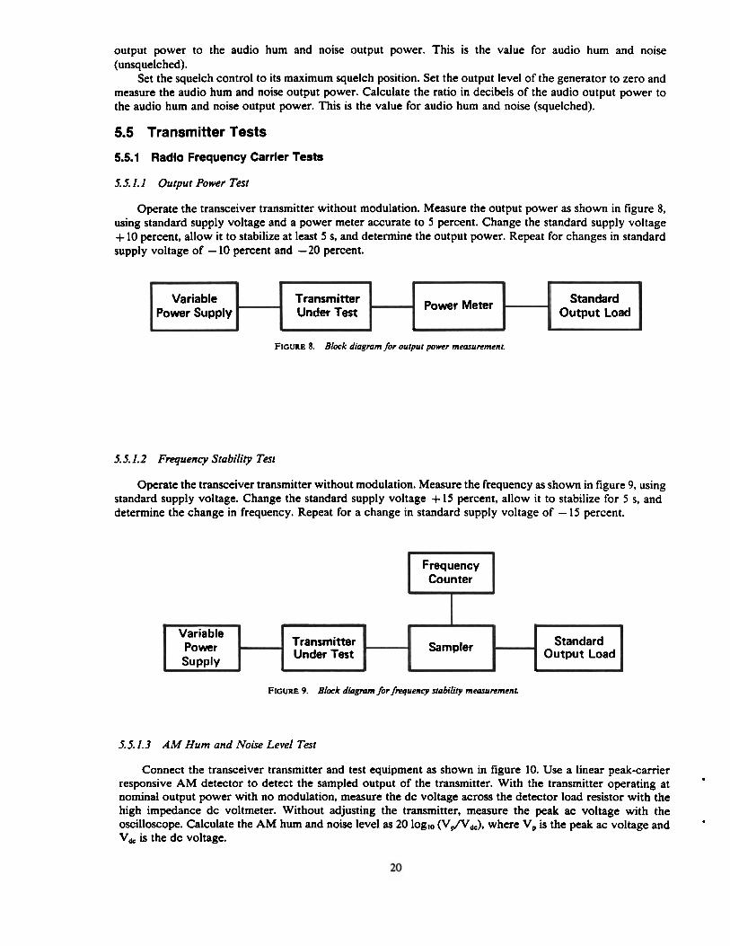
Operate the transceiver transmitter without modulation. Measure the output power as shown in figure 8, using standard supply voltage and a power meter accurate to 5 percent. Change the standard supply voltage + 10 percent, allow it to stabilize at least 5 s, and determine the output power. Repeat for changes in standard supply voltage of - 10 percent and -20 percent.
FIGURE 8. Block diagmm for output power measurement.
5.5.1.2 Frequency Stability Test
Standard Output Load
Variable Power Supply
Operate the transceiver transmitter without modulation. Measure the frequency as shown in figure 9, using standard supply voltage. Change the standard supply voltage + 15 percent, allow it to stabilize for 5 s, and determine the change in frequency. Repeat for a change in standard supply voltage of - 15 percent.
FIGURE 9. Block diagmm f i r frequency stability measurement.
Power Meter 1 ransmitter Under Test
r
Frequency Counter
5.5.1.3 AM Hum and Noise Level Test
'
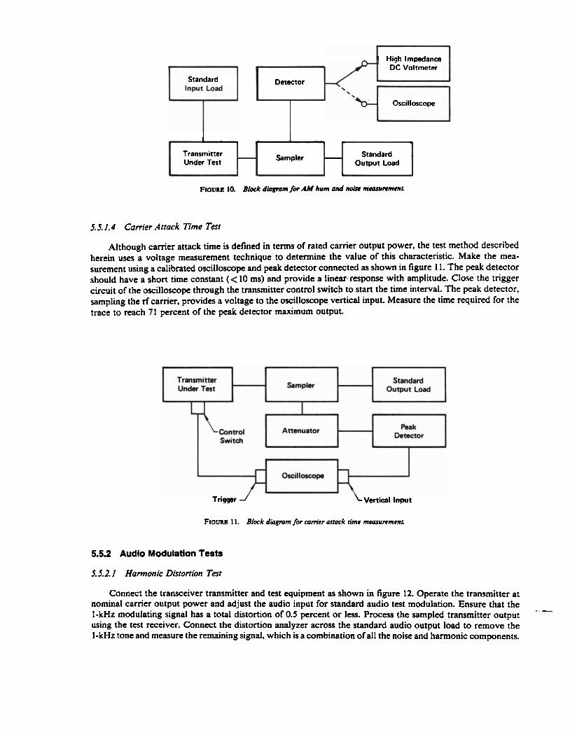
Connect the transceiver transmitter and test equipment as shown in figure 10. Use a linear peakcamer responsive AM detector to detect the sampled output of the transmitter. With the transmitter operating at nominal output power with no modulation, measure the dc voltage across the detector load resistor with the high impedance dc voltmeter. Without adjusting the transmitter, measure the peak ac voltage with the oscilloscope. Calculate the AM hum and noise level as 20 loglo (Vfl,), where V, is the peak ac voltage and V, is the dc voltage.
Standard Output Load
7
Variable Power Supply
Sampler Transmitter Under Test
-
High lmpI!dan~ DC Voltmeter
Standard Detector
Oscilloscope
Transmitter Sampler Standard Under Test Output Load
noum 10. B k k dlogmm fbr AM hum and no& mamvrrnrmr
5.5.1.4 Comer Attack Time Test
Although carrier attack time is defined in terms of rated carrier output power, the test method described herein uses a voltage measurement technique to determine the value of this characteristic. Make the mea- surement using a calibrated oscilloscope and peak detector connected as shown in figure 1 1. The peak detector should have a short time constant (< 10 ms) and provide a 1inear.response with amplitude. Close the trigger circuit of the oscilloscope through the transmitter control switch to start the time interval. The peak detector, sampling the rf carrier, provides a voltage to the oscilloscope vertical input. Measure the time required for the trace to reach 71 percent of the peak detector maximum output.
I Trmsmittar Standard Undar Test H smpk H O u m t L d
I (hcillorcopa 1
Vertical Input
FIOURE 11. Block diagmm for canier attack time measurement
5.5.2 Audio Modulation Tests
5.5.2. I Harmonic Distortion Test
Connect the transceiver transmitter and test equipment as shown in figure 12. Operate the transmitter at nominal carrier output power and adjust the audio input for standard audio test modulation. Ensure that the 1-kHz modulating signal has a total distortion of 0.5 percent or less. Process the sampled transmitter output ---
using the test receiver. Connect the distortion analyzer across the standard audio output load to remove the 1-kHz tone and measure the remaining signal, which is a combination of all the noise and harmonic components.

Variable Attenuator
Audio Generator
Distortion Analyzer Audio Output
Transmitter Standard - Under Test - Sampler - Output
Load
FIQURE 12. Block diagmm for hannonic dirtonion and FM hum and noise measurements,
1
5.5.2.2 FM Hum and Noise Level Test
Connect the transceiver transmitter and test equipment as shown in figure 12. Operate the transmitter at nominal camer output power and adjust the audio input for standard audio test modulation. Measure the audio output voltage, V,, of the test receiver using the distortion analyzer as a voltmeter. Remove the modulation by disconnecting the audio generator and replacing it with the standard audio input load (sec. 5.2.8). Measure the resulting audio voltage, V,, at the distortion analyzer. Calculate the FM hum and noise level as 20 log,, (V,/V,). The method provides reliable measurements up to 50 dB.
5.5.2.3 Audio Response Test
Connect the transceiver transmitter and test equipment as shown in figure 13, using a broadband matching network (sec. 4.2) to match the audio generator output impedance to the transmitter audio input load.
Apply selected audio frequencies from 0.3 to 3 kHz to the transmitter, and maintain the audio input level at a constant 30 percent of rated system deviation (i.e., 1.5 kHz) as observed with the deviation meter. Determine the audio voltmeter reading in decibels relative to the voltmeter reading at 1 kHz for each test frequency, and draw-a graph similar to that shown in figure 1.
1lYdd1 volt- Variable ,
Attenuator
Audio Generator
#
Deviation 1-1 FIQURE 13. Block diagram for audio response mcanrrcmcnr
- - - Matching Network
Transmitter Unda Test Sampler - Standard
Output Load
"
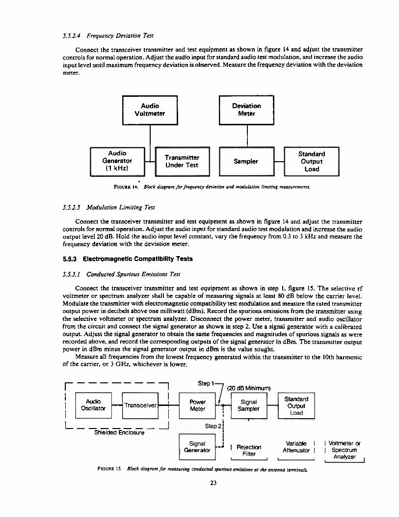
5.5.2.4 Frequency Deviation Test
Connect the transceiver transmitter and test equipment as shown in figure 14 and adjust the transmitter controls for normal operation. Adjust the audio input for standard audio test modulation, and increase the audio input level until maximum frequency deviation is observed. Measure the frequency deviation with the deviation meter.
Deviation Meter
Audio Voltmeter
Standard Sampler Output
FIGURE 14. Block diagmm /or frequency deviation and modulation limiting measurementr
5.5.2. 5 ibfodulation Limiting Test
Transmitter Under Test
r
Audio Generator (1 kHz)
Connect the transceiver transmitter and test equipment as shown in figure 14 and adjust the transmitter controls for normal operation. Adjust the audio input for standard audio test modulation and increase the audio output level 20 dB. Hold the audio input level constant, vary the frequency from 0.3 to 3 kHz and measure the frequency deviation with the deviation meter.
LC
5.5.3 Electromagnetic Compatibility Tes ts
5.5.3.1 Conducted Spurious Emissions Test
Connect the transceiver transmitter and test equipment as shown in step 1, figure 15. The selective rf voltmeter or spectrum analyzer shall be capable of measuring signals at least 80 dB below the carrier level. Modulate the transmitter with electromagnetic compatibility test modulation and measure the rated transmitter output power in decibels above one milliwatt (dBm). Record the spurious emissions from the transmitter using the selective voltmeter or spectrum analyzer. Disconnect the power meter, transmitter and audio oscillator from the circuit and connect the signal generator as shown in step 2. Use a signal generator with a calibrated output. Adjust the signal generator to obtain the same frequencies and magnitudes of spurious signals as were recorded above, and record the corresponding outputs of the signal generator in dBm. The transmitter output power in dBm minus the signal generator output in dBm is the value sought.
Measure all frequencies from the lowest frequency generated within the transmitter to the 10th harmonic of the carrier, or 3 GHz, whichever is lower.
I
I i t , -, - - - Step 2 ; Shielded Enclosure
Variable I I Voltmeter or Generator Filter Attenuator r 1 Spectrum
, Analyzer
FIGURE IS. Block diagram for measuring conducted spurious emisions at the antenna terminals
r ------- 1 Step 1 (20 dB Minimum)
I 1 I
Transceiver Audio
~scillator
I Standard
Meter Output 1 -

5.5.3.2 Radiated Spurious Emissions Test (Type I and II Transceivers)
Set up the mobile trar-sceiver and the test equipment as shown in figure 16 at a site that meets the requirements of section 5.1.8.1. Connect the transmitter to the standard output load and adjust it to produce nominal ouput power. Measure the spurious emissions with the receiving antenna 30 m (98.4 ft) from the transmitter and 3 m (9.8 ft) above the earth. Tune the field strength meter from the lowest radio frequency generated in the mobile transmission equipment up to the 10th harmonic of the carrier or 1000 MHz, whichever is lower. Note each spurious emission.
For each spurious frequency noted, raise and lower the receiving antenna with a horizontal polarization to obtain a maximum reading on the field strength receiver. Rotate the transmitter to further maximize this reading. Repeat this procedure of raising and lowering the antenna and rotating the transmitter until the largest signal has been obtained and recorded. Then orient the antenna for vertical polarization and repeat the procedure for each spurious signal. Record the maximum field strength of the spurious frequencies.
Field
Transceiver Turntable - Strength
Receiver
FIGURE 16. Block diagmm for mdiated spurious emission measurement for type I and II transceivers
5.5.3.3 Radiated Spurious Emissions Test (Type III and IV Transceivers)
Set up the mobile transceiver and the test equipment as shown in figure 17 at a site that meets the requirements of section 5.1.8.2. Place the microwave absorber, at least 1.8 m (6 ft) wide, on the ground between the mobile transceiver and the receiving antenna, as shown. Connect the transmitter to the standard output load and adjust it to produce nominal output power. Measure the spurious emissions with both the receiving antenna and the transmitter 1 m (3.3 ft) above the earth and the horizontally-polarized receiving antenna 3 m (9.8 ft) from the transmitter. Tune the field strength meter from the lowest radio frequency generated in the equipment up to 3 GHz. Note each spurious emission.
Standard
Field - Strength Receiver
1-3 rn
FIGURE 17. Block diagram for mdiated spurious emission measurement for type III and I V tmnsceiwrs
24

For each spurious frequency noted, raise and lower the receiving antenna with a horizontal polarization to obtain a maximum reading on the field strength receiver. Rotate the transmitter to further maximize this reading. Repeat this procedure of raising and lowering the antenna and rotating the transmitter until the largest signal has been obtained and recorded. Then orient the antenna for vertical polarization and repeat the procedure for each spurious signal. Record the maximum field strength of the spurious frequencies.
5.5.3.4 Sideband Spectrum Test
Connect the transceiver transmitter and test equipment as shown in figure 18. Using the variable attenu- ator. adjust the unmodulated carrier signal for a full-scale signal at least 60 dB above the noise as displayed on the spectrum analyzer. Apply electromagnetic compatibility test modulation and measure the average envelope of the resulting spectrum at both k 10 kHz and k20 kHz from the center frequency. Adjust the spectrum analyzer controls so that approximately 50 kHz of transmitter spectrum is centered on the display. The image on the cathode ray tube of the spectrum analyzer should be similar to that shown in figure 19.
~ ~ r a n ~ i m r 1-1 SrnpIer H -.Ier H I Under Test
Variable
Deviation ,,I FIGURE 18. Block diagram for sideband spectmm mcosurrmmt.
Frequency (kHz)
FIGURE 19. Typical sideband spectmm of a tmnrmimr using 4-25 kHz tone 16 dB greater than that required to produce e2.5 kHz deviation at 1.0 kHz
Record the sideband spectrum attenuations as the differences between the center frequency amplitude and the amplitudes of the sidebands located at + 10 kHz and k20 kHz from the center frequency.
APPENDIX A-REFERENCES
[I] Greene, F. M. Technical terms and definitions used with law enforcement communications equipment. LESP-RPT-0203.00. National Institute of Justice, U.S. Department of Justice, Washington, D C 20531; 1973 June.
[2] Private land mobile radio services. Federal Communications Commission. Rules and Regulations, Vol. 5, Part 90. Federal Communications Commission, 1919 M Street, NW., Washington, D C 20554.

APPENDIX B-BIBLIOGRAPHY
Continuous signal-controlled selective signaling. NIJ Standard-0219.00. National Institute of Justice, U.S. Department of Justice, Washington, DC 2053 1; 1980 August.
Control heads and cable assemblies for mobile FM transceivers. NIJ Standard42 16.00. National Institute of Justice, U.S. Department of Justice. Washington, DC 20531; 1981 December.
Greene, F. M. NBS field-strength standards and measurements (30 Hz to 100 MHz). Proceedings IEEE 55(6): 970-981. Institute of Electrical and Electronics Engineers, Inc., 345 East 47th St., New York, NY; 1967 June.
Microphone cable assemblies for mobile FM transceivers. NIJ Standard-0217.00. National Institute of Justice, U.S. Department of Justice, Washington, DC 20531; 1980 August.
Minimum standards for communication antennas, Part 11-Vehicular antennas. EIA Standard RS-329-1. Electronic Industries Association, 2001 Eye St., NW., Washington, DC 20006; 1972 August.
Minimum standards for land mobile communication FM or PM receivers, 25-947 MHz. EIA Standard RS-204-C. Electronic Industries Association, 2001 Eye St., NW.,, Washington, DC 20006; 1982 January.
Minimum standards for land mobile communication FM or PM transmitters, 25-470 MHz. EIA Standard RS-152-B. Electronic Industries Association, 2001 Eye St., NW., Washington, DC 20006; 1970 February.
Minimum standards for portable/personal radio transmitters, receivers and transmitterheceiver combi- nation land mobile communications FM or PM equipment, 25-1000 Hz. EIA Standard RS-316- B. Electronic Industries Association, 2001 Eye St., NW., Washington, DC 20006; 1979 May.
Mobile antennas. NILECJ-STD-0205.00. National Institute of Justice, U.S. Department of Justice, Washington, DC 20531; 1974 May.
Mobile stations FM or PM radiotelephone transceivers operating in certain VHF/UHF bands in the frequency range 27.23 MHz to 470 MHz with RF power output rating not exceeding 10 watts. Canada Dept. of Communications Standard RSS 121; 1971 April 15.
RF coaxial cable assemblies for mobile transceivers. NILECJ-STD-0212.00. National Institute of Justice, U.S. Department of Justice, Washington, DC 20531; 1975 September.
Runyon, S. Focus on signal generators and synthesizers. Electronic Design 21(10); 1973 May 10. Society of Automotive Engineers, Inc. Capacitor, 10 MFD for EM1 measurements. Aerospace Recom-
mended Practice, ARP 936; 1968 May 31. Taggart, H. E. Field strength calibration techniques at the National Bureau of Standards. iEEE Trans.
Electromagnetic Compatibility. EMC-7, No. 2. Institute of Electrical and Electronics Engineers, Inc., 345 East 47th Street, New York, NY; 1965 June.
Taggart, H. E. Methods of suppressing automotive interference. Natl. Bur. Stand. (U.S.) Spec. Pub. 480-44; 198 1 November.
Taggart, H. E.; Workman, J. L. Calibration principles and procedures for field strength meters (30 Hz to 1 GHz). Natl. Bur. Stand. (U.S.) Tech. Note 370; 1969 March.
White, D. R. J. A handbook of electrical noise and electromagnetic interference specifications, Vol. 1. Don White Consultants, Gainesville, VA; 1971.