mobile launcher 2 (ml2) table of contents 80ksc019c0013€¦ · mobile launcher 2 (ml2) table of...
TRANSCRIPT


Mobile Launcher 2 (ML2) Table of Contents 80KSC019C0013
3
TABLE OF CONTENTS SECTION A – SF1442 ...................................................................................................... 1 SECTION B - SUPPLIES OR SERVICES AND PRICE/COSTS ............................... 5 SECTION C - DESCRIPTION/SPECIFICATION/WORK STATEMENT .............. 9 SECTION D - PACKAGING AND MARKING.......................................................... 11 SECTION E - INSPECTION AND ACCEPTANCE .................................................. 12 SECTION F - DELIVERIES OR PERFORMANCE.................................................. 16 SECTION G – CONTRACT ADMINISTRATION DATA ........................................ 16 SECTION H - SPECIAL CONTRACT REQUIREMENTS ...................................... 24 SECTION I - CONTRACT CLAUSES ........................................................................ 29 SECTION J - LIST OF ATTACHMENTS .................................................................. 42 J ATTACHMENTS
J-1 – ML2 STATEMENT OF WORK J-2 – KSC PROJECT SPECIFIC DELIVERABLES J-3 – KSC PROJECT SPECIFIC REQUIREMENTS J-4 – DATA REQUIREMENTS LIST (DRL) J-5 – LOGISTICS PRODUCTS AND DATA J-6 – DESIGN PRODUCT DEFINITIONS/EXPECTATIONS J-7 – GOVERNMENT FURNISHED EQUIPMENT (GFE) J-8 – HANDLING AND ACCESS J-9 – GLOSSRY OF TERMS/ACRONYM LIST J-10 – COMPLIANCE DOCUMENTS J-11 – REFERENCE DOCUMENTS J-12 – COST AND FUNDING SCHEDULES J-13 – AWARD FEE EVALUATION PLAN J-14 – KEY PERSONNEL MINIMUM QUALIFICATIONS J-15 – CONSTRUCTION WAGE RATE REQUIREMENTS
DATA REQUIREMENTS DOCUMENTS (DRDs) 1.0-1 – MONTHLY PROJECT MANAGEMENT STATUS REVIEW

Mobile Launcher 2 (ML2) Table of Contents 80KSC019C0013
4
1.0-2 – SITE SPECIFIC SAFETY AND HEALTH PLAN 1.0-3 – CONFIGURATION MANAGEMENT PLAN 1.0-4 – FINANCIAL MANAGEMENT REPORTS (E533) 1.0-5 – FINANCIAL MANAGEMENT REPORTS (533) 1.0-6 – CONTRACTOR INTEGRATED PERFORMANCE MEASUREMENT
REPORT (IPMR) 1.0-7 – CONTRACT WORK BREAKDOWN STRUCTURE (CWBS) 1.0-8 – FIRM FIXED PRICE PROPOSAL 1.0-9 – EARNED VALUE MANAGEMENT PLAN 1.0-10 – PHASED NEGOTIATED ESTIMATED COST REPORT


Mobile Launcher 2 (ML2) Section C Description/Specification/Work Statement 80KSC019C0013
9
SECTION C - DESCRIPTION/SPECIFICATION/WORK STATEMENT
C.1 SCOPE OF WORK The Contractor shall furnish as specified in Section B.1, Construction Services and Prices, all management, supervision, labor, transportation, facilities, materials, tools, disposal, coordination of subcontractors, documentation, and equipment (except any property including utilities as may be specified in the Schedule to be Government-Furnished), and perform all work in accordance with Attachment J-1, Statement of Work.
(End of clause)
C.2 REQUEST FOR INFORMATION/CLARIFICATION (RFI/C) The Contractor shall promptly report to the Contracting Officer all problems or conflicting technical information encountered during the contract performance so that the Government may provide solutions or appropriate direction. The Contractor shall report such problems by submitting a “Request for Information/Clarification” through the web-based application provided by the Contractor. The Contractor shall log and control each RFI/C, including those generated by subcontractors.
(End of clause)
C.3 DEVIATIONS AND WAIVERS (DW)
(a) When the Contractor proposes to perform work which does not conform to the requirements of the applicable contract drawings and specifications, the Contractor shall submit to the Contracting Officer for approval, a written request for deviation or request for waiver on the nonconforming work.
(b) The Contractor shall submit all requests as a Deviation Waiver (Contractor Request to
Use Nonconforming Parts or Material) including an offer of consideration to the Government. The DW must be submitted through the web-based application provided by the Contractor. The Contractor shall technically support the request with justification, rationale, design considerations, calculations, and other data which permits ready and conclusive evaluation by the Government as to acceptability or non-acceptability.
(c) Where a requested deviation or waiver on a particular aspect of the work has a
relation to, or affects, other aspects of the work, the Contractor shall clearly identify and reference those other aspects of the work. And, if the requested deviation or waiver necessitates a deviation or waiver on other aspects, the Contractor shall submit requests for all such deviations and waivers concurrently.

Mobile Launcher 2 (ML2) Section C Description/Specification/Work Statement 80KSC019C0013
10
(d) Any request not submitted in strict accordance with this provision will not be considered.
(End of clause)

Mobile Launcher 2 (ML2) Section D – Packaging and Marking 80KSC019C0013
11
SECTION D - PACKAGING AND MARKING
D.1 RESERVED

Mobile Launcher 2 (ML2) Section E Inspection and Acceptance 80KSC019C0013
12
SECTION E - INSPECTION AND ACCEPTANCE
E.1 CLAUSES INCORPORATED BY REFERENCE
Clauses at the beginning of this Section are incorporated by reference, with the same force and effect as if they were given in full text. Clauses incorporated by reference which require a fill-in by the Government include the text of the affected paragraphs only. This does not limit the clause to the affected paragraphs. The Contractor is responsible for understanding and complying with the entire clause. The full text of the clause is available at the addresses contained in clause 52.252-2, Clauses Incorporated by Reference, of this contract.
(End of clause)
E.2 LISTING OF FEDERAL ACQUISITION REGULATION (48 CFR CHAPTER 1) CLAUSES INCORPORATED BY REFERENCE
52.246-3 Inspection of Supplies—Cost Reimbursement (MAY 2001) 52.246-11 Higher-Level Contract Quality Requirement (DEC 2014)
Paragraph (a) fill-in: Reference Section E.4, Quality Requirements, and Attachment J-1, Statement of Work
(End of text)
E.3 1852.246-72 MATERIAL INSPECTION AND RECEIVING REPORT (APR 2015)
(a) At the time of each delivery to the Government under this contract, the Contractor shall prepare and furnish a Material Inspection and Receiving Report (DD Form 250 series). The forms shall be prepared and distributed as follows: two copies to the Contracting Officer.
(b) The Contractor shall prepare the DD Form 250 in accordance with NASA FAR
Supplement 1846.6. The Contractor shall enclose the copies of the DD Form 250 in the package or seal them in a waterproof envelope, which shall be securely attached to the exterior of the package in the most protected location.
(c) When more than one package is involved in a shipment, the Contractor shall list on
the DD Form 250, as additional information, the quantity of packages and the package numbers. The Contractor shall forward the DD Form 250 with the lowest numbered package of the shipment and print the words "CONTAINS DD FORM 250" on the package.
(End of clause)

Mobile Launcher 2 (ML2) Section E Inspection and Acceptance 80KSC019C0013
13
E.4 QUALITY REQUIREMENTS
(a) Construction Quality Control - General The Contractor shall maintain an effective Quality Program that encompasses all actions involving selection of construction materials and sources, suppliers, subcontractors, on-site and off-site fabrication of Contractor-furnished items to be included in the work; on-site and off-site assembly, erection, work-placement procedures, workmanship, inspection, and testing. The Contractor's program shall provide for a functional system of records to provide objective evidence that the Quality provisions of the contract schedule, specifications, and drawings have been satisfactorily performed and recorded. The Contractor shall provide all documentation which assures deliverable hardware/material has been fabricated, inspected, tested, and shipped as required by the contract. The Contractor shall maintain all documentation at all times during the contract, at the same status as the deliverable hardware.
The Contractor shall establish and maintain a quality control system that satisfies the requirements of AS9100, Quality Systems-Model for Quality Assurance in Production, Installation, and Serving, and the amendments thereto as described below.
(b) Management and Organization The Contractor shall provide an effective management structure to support the requirements of the Quality Program.
(c) Quality Assurance (QA) Plan (1) The Contractor shall prepare a quality assurance plan in accordance with AS 9100
and collaborate with the Government on the content of the plan during the design charrette process. Within 30 calendar days after Contract Award, the contractor shall submit an electronic copy of its initial QA plan for Government review. Within 60 calendar days after receipt of Government comments, the Contractor shall submit its final QA plan, for Government review and approval. The Contractor shall maintain a revised/updated QA plan throughout the contract duration.
(2) The plan must describe how the Contractor will ensure compliance with the
quality requirements of the Specifications for both on-site and off-site work.
(d) Government Inspections
The Government reserves the right to inspect any or all of the materials included on this Contract at the Contractor's facility and the facilities of their subcontractors. The

Mobile Launcher 2 (ML2) Section E Inspection and Acceptance 80KSC019C0013
14
frequency of Government source inspection will be determined by the Contracting Officer. Source inspection performed by the Government on procured articles or materials shall not replace Contractor inspection nor relieve the Contractor of the responsibility for ensuring the quality of procured articles and materials.
(e) Receiving Inspection Systems
The Contractor shall maintain a Receiving Inspection System which ensures that all procured materials and equipment are inspected and tested as prescribed by the applicable specifications and drawings, and the approved Submittal Documents (SDs).
(f) Nonconforming Articles/And Material Control The Contractor shall ensure control and recording of non-conformances discovered by the Contractor, subcontractors, and suppliers or designated Government quality representatives to prevent their use and to correct deficient operations and procedures.
(g) Quality Records The Contractor shall maintain all quality records in a central location, in a searchable electronic format. These records must include all quality control data; factory tests or manufacturer's certification, quality control coordinating actions; records of quality control training/certifications as well as routine hydrostatic, electrical continuity, grounding, welding, line cleaning, and similar tests. The quality records must be available for examination by the Contracting Officer, and the Contractor shall provide copies of tests, and data to the Contracting Officer's on-site representative(s).
(h) Responsibility for Inspection and Testing
The Contractor shall assume responsibility for all inspections and tests and for the accompanying documentation. The Contractor shall use independent inspection and testing laboratories or services. The Contractor shall assume responsibility for test of construction materials performed by an approved independent testing laboratory.
(i) Inspection and Test Records The Contractor shall maintain current records on site of each inspection and test performed throughout the life of the contract.
(j) Inspection, Measuring, and Test Equipment – Calibration The Contractor shall have a system to provide and maintain currently calibrated gages, and other measuring and testing devices necessary to assure that the work conforms to contract requirements.

Mobile Launcher 2 (ML2) Section E Inspection and Acceptance 80KSC019C0013
15
(k) Weld Inspection and NACE (National Association of Corrosion Engineers) Inspection and Testing The Contractors shall coordinate with the Government’s Inspector or representative in regard to the inspection, testing schedule, documentation, and submission of the inspection and test reports. The Contractor shall maintain a structured system for documenting weld inspection and testing. The system shall contain identification of each weld (e.g. weld map), the inspector’s approval, and traceability to the respective non-destructive test record. The Contractor shall keep weld and NACE Inspection Reports current and accessible to the Government at all times. The Contractor shall make documented weld reports available within one week post testing and prior to coating. The Contractor shall notify the Government of any failed tests or trends which indicate potential equipment or specific welder qualification issues. The weld reports shall be included in the Acceptance Data Package.
(l) Quality Program Audits The Contractor’s program is subject to continuous review and verification by the Contracting Officer or designated representatives. The Contractor shall establish its own system of scheduled or random audits of its program to assure the objectives are met.
(End of clause)

Mobile Launcher 2 (ML2) Section F Deliveries or Performance 80KSC019C0013
16
SECTION F - DELIVERIES OR PERFORMANCE
F.1 CLAUSES INCORPORATED BY REFERENCE Clauses at the beginning of this Section are incorporated by reference, with the same force and effect as if they were given in full text. Clauses incorporated by reference which require a fill-in by the Government include the text of the affected paragraphs only. This does not limit the clause to the affected paragraphs. The Contractor is responsible for understanding and complying with the entire clause. The full text of the clause is available at the addresses contained in clause 52.252-2, Clauses Incorporated by Reference, of this contract.
(End of clause)
F.2 LISTING OF FEDERAL ACQUISITION REGULATION (48 CFR CHAPTER 1) CLAUSES INCORPORATED BY REFERENCE 52.242-14 Suspension of Work (APR 1984)
F.3 RESERVED
F.4 DOWNTIME AND EXCAVATION HOLDS The Contractor shall allow in its bid for up to 10 calendar days during which all construction activities will be prohibited and the contractor may be denied access to the work site. In addition, the Contractor shall allow for up to five calendar days during which all excavation and other subsurface activities will be prohibited but other construction activities will be allowed. The Government will provide 24 hours’ notice each time these restrictions are invoked.
(End of clause)
F.5 PLACE OF PERFORMANCE
Although the Contractor may elect to construct some of ML2 at an alternate location, the Contractor shall perform the final assembly at Kennedy Space Center (KSC) at the location designated in the Statement of Work.
(End of clause)
F.6 COMMENCEMENT, PROSECUTION, AND COMPLETION OF WORK
The Contractor shall be required to (a) commence work under this contract within one day after the date of contract award, (b) prosecute the work diligently, and (c) complete the entire work ready for use not later than 44 months after the date of contract award. The time stated for completion shall include final cleanup of the premises.
(End of clause)

Mobile Launcher 2 (ML2) Section G Contract Administration Data 80KSC019C0013
17
SECTION G – CONTRACT ADMINISTRATION DATA
G.1 CLAUSES INCORPORATED BY REFERENCE
Clause(s) at the beginning of this Section are incorporated by reference, with the same force and effect as if they were given in full text. Clauses incorporated by reference which require a fill-in by the Government include the text of the affected paragraph(s) only. This does not limit the clause to the affected paragraph(s). The Contractor is responsible for understanding and complying with the entire clause. The full text of the clause is available at the addresses contained in clause 52.252-2, Clauses Incorporated by Reference, of this contract.
(End of clause)
G.2 LISTING OF NASA FEDERAL ACQUISITION REGULATION (48 CFR CHAPTER 18) CLAUSES INCORPORATED BY REFERENCE
1852.223-71 Authorization for Radio Frequency Use (APR 2015)
1852.242-73 NASA Contractor Financial Management Reporting (NOV 2004)
1852.245-70 Contractor Requests for Government-furnished Property (AUG
2015)(ALT I 2015)
1852.245-75 Property Management Changes. (JAN 2011)
1852.245-78 Physical Inventory of Capital Personal Property. (AUG 2015)
(End of text)
G.3 1852.216-77 AWARD FEE FOR END ITEM CONTRACTS (AUG 2016)
(a) The contractor can earn award fee, or base fee, if any, from a minimum of zero
dollars to the maximum stated in Section B.1, Construction Services and Prices, in this contract. All award fee evaluations, with the exception of the last evaluation, will be interim evaluations. At the last evaluation, which is final, the Contractor's performance for the entire contract will be evaluated to determine total earned award fee. No award fee or base fee will be paid to the Contractor if the final award fee evaluation is “poor/unsatisfactory.”
(b) Beginning six months after the effective date of this contract, the Government will
evaluate the Contractor's interim performance every six months to monitor Contractor performance prior to contract completion and to provide feedback to the Contractor. The evaluation will be performed in accordance with Attachment J-13, Award Fee Evaluation Plan, to this contract. The Contractor may submit a self-evaluation of performance for each period under consideration. These self-evaluations will be considered by the Government in its evaluation. The Government will advise the

Mobile Launcher 2 (ML2) Section G Contract Administration Data 80KSC019C0013
18
Contractor in writing of the evaluation results. The plan may be revised unilaterally by the Government prior to the beginning of any rating period to redirect emphasis.
(1) Base fee, if applicable, will be paid in N/A installments based on the percent of
completion of the work as determined by the Contracting Officer.
(2) Interim award fee payments will be made to the Contractor based on each interim evaluation. The amount of the interim award fee payment is limited to the lesser of the interim evaluation score or 80 percent of the fee allocated to that period less any provisional payments made during the period. All interim award fee payments will be superseded by the final award fee determination.
(3) Provisional award fee payments will be made under this contract pending each
interim evaluation. If applicable, provisional award fee payments will be made to the Contractor on a monthly basis. The amount of award fee which will be provisionally paid in each evaluation period is limited to 80 percent of the prior interim evaluation score (Table B.3 Award Fee) except for the first evaluation period which is limited to 80 percent of the available award fee for that evaluation period. Provisional award fee payments made each evaluation period will be superseded by the interim award fee evaluation for that period. If provisional payments made exceed the interim evaluation score, the Contractor will either credit the next payment voucher for the amount of such overpayment or refund the difference to the Government, as directed by the Contracting Officer. If the Government determines that
(i) the total amount of provisional fee payments will apparently substantially exceed the anticipated final evaluation score, or
(ii) the prior interim evaluation is “poor/unsatisfactory,” the Contracting Officer will direct the suspension or reduction of the future payments and/or request a prompt refund of excess payments as appropriate. Written notification of the determination will be provided to the Contractor with a copy to the Deputy Chief Financial Officer (Finance).
All interim (and provisional, if applicable) fee payments will be superseded by the fee determination made in the final award fee evaluation. The Government will then pay the Contractor, or the Contractor will refund to the Government the difference between the final award fee determination and the cumulative interim (and provisional, if applicable) fee payments. If the final award fee evaluation is “poor/unsatisfactory,” any base fee paid will be refunded to the Government.
(4) Payment of base fee, if applicable, will be made based on submission of an
invoice by the Contractor. Payment of award fee will be made by the NASA Shared Services Center (NSSC) at the direction of the Contracting Officer.
(c) The Contracting Officer may direct the withholding of interim award fee payments
until a reserve is set aside in an amount that the Contracting Officer considers

Mobile Launcher 2 (ML2) Section G Contract Administration Data 80KSC019C0013
19
necessary to protect the Government's interest relative to an orderly and timely closeout of the contract. This reserve shall not exceed 15 percent of the contracts total potential award fee or $100,000, whichever is less.
(d) Award fee determinations are unilateral decisions made solely at the discretion of the
Government.
(End of clause)
G.4 1852.232-80 SUBMISSION OF VOUCHERS/INVOICES FOR PAYMENT (APR 2018)
(a) The designated payment office is the NASA Shared Services Center (NSSC) located
at FMD Accounts Payable, Bldg. 1111, Jerry Hlass Road, Stennis Space Center, MS 39529.
(b) Except for classified vouchers, the Contractor shall submit all vouchers and invoices using the steps described at NSSC’s Vendor Payment information web site at: https://www.nssc.nasa.gov/vendorpayment. Please contact the NSSC Customer Contact Center at 1-877-NSSC123 (1-877-677-2123) with any additional questions or comments.
(c) Payment requests. (1) The payment periods are stipulated in the payment clause(s) contained in this
contract.
(2) Vouchers submitted under cost-type contracts and invoices submitted under fixed-price contracts shall include the items delineated in FAR 32.905(b) supported by relevant back-up documentation. Back-up documentation shall include at a minimum, the following information:
(i) Vouchers.
a. Breakdown of billed labor costs and associated contractor generated supporting documentation for billed direct labor costs to include rates used and number of hours incurred.
b. Breakdown of billed other direct costs (ODCs) and associated contractor generated supporting documentation for billed ODCs.
c. Indirect rate(s) used to calculate the amount of billed indirect expenses.
d. Progress reports, as required. (ii) Invoices.
a. Description of goods and services delivered as part of the contract’s terms and conditions, including the dates of delivery/performance.
b. Progress reports, as required.

Mobile Launcher 2 (ML2) Section G Contract Administration Data 80KSC019C0013
20
c. Date goods and services were performed. (iii) Fee vouchers.
a. Listing of all provisionally-billed fee by period or date earned since contract award.
b. A reconciliation of all billed and earned fee. c. A clear explanation of the fee calculations.
(d) Non-electronic payment requests. The Contractor may submit a non-electronic
voucher/invoice using the steps for non-electronic payment requests described at https://www.nssc.nasa.gov/vendorpayment, when any of the following conditions are met: (1) The Contracting Officer administering the contract for payment has determined,
in writing, that electronic submission would be unduly burdensome to the Contractor.
(2) The contract includes provisions allowing the contractor to submit vouchers or invoices using the steps for non-electronic payment requests. In such instances the Contractor agrees to submit non-electronic payment requests using the method or methods specified in Section G of the contract.
(e) Improper vouchers/invoices. The NSSC Payment Office will notify the contractor of
any apparent error, defect, or impropriety in a voucher/invoices within seven calendar days of receipt by the NSSC Payment Office. Inquiries regarding requests for payment should be directed to the NSSC as specified in paragraph (b) of this section.
(f) Other payment clauses. In addition to the requirements of this clause, the Contractor shall meet the requirements of the appropriate payment clauses in this contract when submitting payment requests.
(g) In the event that amounts are withheld from payment in accordance with provisions of this contract, a separate payment request for the amount withheld will be required before payment for that amount may be made.
(End of clause)
G.5 1852.245-71 INSTALLATION-ACCOUNTABLE GOVERNMENT PROPERTY
(JUN 2018)
(a) The Government property described in paragraph (c) of this clause may be made available to the Contractor on a no-charge basis for use in performance of this contract. This property shall be utilized only within the physical confines of the NASA installation that provided the property unless authorized by the Contracting Officer under (b)(1)(iv). Under this clause, the Government retains accountability for, and title to, the property, and the Contractor shall comply with the following:

Mobile Launcher 2 (ML2) Section G Contract Administration Data 80KSC019C0013
21
Kennedy NASA Procedural Requirements (KNPR) 4000.1, Supply and Equipment Program Manual NASA Procedural Requirements (NPR) 4100.1, NASA Materials Inventory Management Manual. NASA Procedural Requirements (NPR) 4200.1, NASA Equipment Management Procedural Requirements. NASA Procedural Requirement (NPR) 4300.1, NASA Personal Property Disposal. Property not recorded in NASA property systems must be managed in accordance with the requirements of the clause at FAR 52.245–1, as incorporated in this contract. The Contractor shall establish and adhere to a system of written procedures to assure continued, effective management control and compliance with these user responsibilities.
In accordance with FAR 52.245-1(h)(1) the contractor shall be liable for property lost, damaged, destroyed, or stolen by the contractor or their employees when determined responsible by a NASA Property Survey Board, in accordance with the NASA guidance in this clause.
(b)
(1) The official accountable recordkeeping, financial control, and reporting of the property subject to this clause shall be retained by the Government and accomplished within NASA management information systems prescribed by the installation Supply and Equipment Management Officer (SEMO) and Financial Management Officer. If this contract provides for the Contractor to acquire property, title to which will vest in the Government, the following additional procedures apply:
(i) The Contractor’s purchase order shall require the vendor to deliver the property to the installation central receiving area.
(ii) The Contractor shall furnish a copy of each purchase order, prior to delivery by the vendor, to the installation central receiving area.
(iii) The Contractor shall establish a record for Government titled property as required by FAR 52.245-1, as incorporated in this contract, and shall maintain that record until accountability is accepted by the Government.
(iv) Contractor use of Government property at an off-site location and offsite subcontractor use requires advance approval of the Contracting Officer and notification of the Industrial Property Officer. The property shall be considered Government furnished and the Contractor shall assume accountability and financial reporting responsibility. The Contractor shall establish records and property control procedures and maintain the property in accordance with the requirements of FAR 52.245–1, Government Property (as incorporated in this contract), until its return to the installation. NASA Procedural Requirements related to property loans shall not apply to offsite use of property by contractors.

Mobile Launcher 2 (ML2) Section G Contract Administration Data 80KSC019C0013
22
(2) After transfer of accountability to the Government, the Contractor shall continue to maintain such internal records as are necessary to execute the user responsibilities identified in paragraph (a) of this clause and document the acquisition, billing, and disposition of the property. These records and supporting documentation shall be made available, upon request, to the SEMO and any other authorized representatives of the Contracting Officer.
(c) The following property and services are provided if checked:
(1) __ Office space, work area space, and utilities. Government telephones are
available for official purposes only. (2) __ Office furniture. (3) X Property listed in Attachment J-7.
(i) If the Contractor acquires property, title to which vests in the Government pursuant to other provisions of this contract, this property also shall become accountable to the Government upon its entry into Government records.
(ii) The Contractor shall not bring to the installation for use under this contract any property owned or leased by the Contractor, or other property that the Contractor is accountable for under any other Government contract, without the Contracting Officer’s prior written approval.
(4) __ Supplies from stores stock. (5) __ Publications and blank forms stocked by the installation. (6) X Safety and fire protection for Contractor personnel and facilities. (7) __ Installation service facilities: none. (8) X Medical treatment of a first-aid nature for Contractor personnel injuries or
illnesses sustained during on-site duty. (9) X Cafeteria privileges for Contractor employees during normal operating hours.
(10) __ Building maintenance for facilities occupied by Contractor personnel. (11) __ Moving and hauling for office moves, movement of large equipment, and
delivery of supplies. Moving services may be provided on-site, as approved by the Contracting Officer.
(End of clause)
G.6 RESERVED
G.7 RESERVED
G.8 1852.245-82 OCCUPANCY MANAGEMENT REQUIREMENTS. (JAN 2011)
(a) In addition to the requirements of the clause at FAR 52.245-1, Government Property,
as included in this contract, the Contractor shall comply with the following in performance of work in and around Government real property:
(1) NPD 8800.14, Policy for Real Property Management.

Mobile Launcher 2 (ML2) Section G Contract Administration Data 80KSC019C0013
23
(2) NPR 8831.2, Facility Maintenance Management.
(b) The Contractor shall obtain the written approval of the Contracting Officer before
installing or removing Contractor-owned property onto or into any Government real property or when movement of Contractor-owned property may damage or destroy Government-owned property. The Contractor shall restore damaged property to its original condition at the Contractor's expense.
(c) The Contractor shall not acquire, construct or install any fixed improvement or structural alterations in Government buildings or other real property without the advance, written approval of the Contracting Officer. Fixed improvement or structural alterations, as used herein, means any alteration or improvement in the nature of the building or other real property that, after completion, cannot be removed without substantial loss of value or damage to the premises. Title to such property shall vest in the Government.
(d) The Contractor shall report any real property or any portion thereof when it is no longer required for performance under the contract, as directed by the Contracting Officer.
(End of clause)

Mobile Launcher 2 (ML2) Section H Special Contract Requirements 80KSC019C0013
24
SECTION H - SPECIAL CONTRACT REQUIREMENTS
H.1 CLAUSES INCORPORATED BY REFERENCE Clause(s) at the beginning of this Section are incorporated by reference, with the same force and effect as if they were given in full text. Clauses incorporated by reference which require a fill-in by the Government include the text of the affected paragraph(s) only. This does not limit the clause to the affected paragraph(s). The Contractor is responsible for understanding and complying with the entire clause. The full text of the clause is available at the addresses contained in clause 52.252-2, Clauses Incorporated by Reference, of this contract.
(End of clause)
H.2 LISTING OF NASA FEDERAL ACQUISITION REGULATION (48 CFR CHAPTER 18) CLAUSES INCORPORATED BY REFERENCE
1852.223-70 Safety and Health Measures and Mishap Reporting (DEC 2015)
1852.223-75 Major Breach of Safety or Security. (FEB 2002)
1852.236-75 Partnering For Construction Contracts (AUG 1998)
1852.242-72 Denied Access to NASA Facilities (OCT 2015)
1852.247-71 Protection of the Florida Manatee. (JUL 2015)
(End of text)
H.3 1852.225-70 EXPORT LICENSES. (FEB 2000)
(a) The Contractor shall comply with all U.S. export control laws and regulations,
including the International Traffic in Arms Regulations (ITAR), 22 CFR Parts 120 through 130, and the Export Administration Regulations (EAR), 15 CFR Parts 730 through 799, in the performance of this contract. In the absence of available license exemptions/exceptions, the Contractor shall be responsible for obtaining the appropriate licenses or other approvals, if required, for exports of hardware, technical data, and software, or for the provision of technical assistance.
(b) The Contractor shall be responsible for obtaining export licenses, if required before utilizing foreign persons in the performance of this contract, including instances where the work is to be performed on-site at John F. Kennedy Space Center (KSC), where the foreign person will have access to export-controlled technical data or software.
(c) The Contractor shall be responsible for all regulatory record keeping requirements associated with the use of licenses and license exemptions/exceptions.

Mobile Launcher 2 (ML2) Section H Special Contract Requirements 80KSC019C0013
25
(d) The Contractor shall be responsible for ensuring that the provisions of this clause apply to its subcontractors.
(End of clause)
H.4 KSC 52.222-6 SPECIAL ENCLAVE STATUS FOR KENNEDY SPACE CENTER
(JUL 2018)
Pursuant to FAR 52.222-6, Construction Wage Rate Requirements: KSC is part of a special enclave within Brevard County which includes the geographic area consisting of KSC, Cape Canaveral Air Force Station, and Patrick Air Force Base, as specified in the attached wage determination. The Department of Labor (DOL) designated KSC as a part of this special enclave in the 1960's during construction of the launch complex. The labor classifications and prevailing wages differ significantly from those contained in wage determinations for the surrounding areas and the process of determining the proper labor classifications for work to be performed may differ significantly from that in a non-enclave environment. Offerors should contact the DOL for instructions concerning selection of proper labor classifications for all KSC construction projects within this special enclave. The DOL local office phone numbers are (321) 242-1851/office and (321) 614-8823/mobile. The selection of the proper labor classifications from the solicitation's wage determination for the pricing of bids/proposals is the responsibility of the offeror in consultation with the DOL. Post award the contractor should continue to be aware of any potential impact KSC's special enclave status might have during contract performance (e.g. contract modifications). It is incumbent upon the offeror to make potential subcontractors aware of KSC's special enclave status and to instruct them to contact DOL for instructions for choosing the proper labor classifications. The Agency will not make any official determination as to the proper labor classifications for work described in this solicitation. The successful offeror shall be solely responsible for the employment of workers with the proper skills and payment of them in accordance with FAR 52.222-6, Construction Wage Rate Requirements, and the solicitation's wage determination. The Agency will monitor contractor compliance in accordance with 29 CFR 5.5. Non-compliance will be reported to the DOL. DOL will determine compliance with the Act and decide on enforcement actions. Any disputes concerning labor standards requirements will be handled by the DOL in accordance with FAR 52.222-14, Disputes Concerning Labor Standards.
(End of clause)
H.5 KSC 52.242-90 CONTROLS APPLICABLE TO CONTRACTOR'S ACTIVITIES (JUL 2018)
The Contractor shall comply with the publications listed and those checked as applicable below, and subsequent revision thereof, that the Contracting Officer has indicated as being incorporated in this contract by reference. These publications prescribe regulatory and

Mobile Launcher 2 (ML2) Section H Special Contract Requirements 80KSC019C0013
26
procedural criteria which are applicable to this contract. The contractor shall promptly take corrective action upon notice of noncompliance from the Contracting Officer or his/her authorized representative(s) with any provision of the publications listed below. The Contractor shall comply with the following publication, which can be found at https://nodis3.gsfc.nasa.gov/displayDir.cfm?t=NPR&c=1600&s=4A: NPR 1600.4A, Identity and Credential Management The Contractor shall comply with the following publications and those publications checked as applicable below. These documents can be found at http://procurement.ksc.nasa.gov/PPD/documents: KNPR 8715.2, Comprehensive Emergency Management Plan (CEMP) KNPR 1600.1, KSC Security Procedural Requirements KNPR 8500.1, KSC Environmental Management Requirements KNPR 8715.3, KSC Safety Procedural Requirements KNPD 1600.3, Use of Alcoholic Beverages on Kennedy Space Center (KSC) Property Check if applicable: [ X ]KNPD 1810.1 KSC Occupational Medicine Program [ X ]KNPR 1860.1 KSC Ionizing Radiation Protection Program [ X ]KNPR 1860.2 KSC Nonionizing Radiation Protection Program [ ]KNPR 1820.3 KSC Hearing Loss Prevention Program [ ]KNPR 1820.4 KSC Respiratory Protection Program [ ]KNPR 1840.19 KSC Industrial Hygiene Programs [ ]45SWI40-201 45th Space Wing Instruction 40-201 Radiation Protection Program [ ]KNPR 1840.1 KSC Hazard Communication Program [ ]KNPR 1870.1 KSC Sanitation and Public Health Program [ ]KNPR 2570.1 KSC Radio Frequency Spectrum Management Procedural Requirements [ X ]KNPR 4000.1 Supply and Equipment System Manual [ X ]KNPR 6000.1 KSC Transportation Support System Manual [ X ]KNPR 8715.7 KSC Construction Contractor Safety and Health Practices Procedural Requirements [ X ]KNPR 8830.1 Facility Asset Management Procedural Requirements
(End of clause)
H.6 KSC 52.242-93 CONTRACTOR WORKFORCE REPORT - ONSITE CONTRACTORS AND SUBCONTRACTORS (JUL 2018)
The Contractor shall submit, on a quarterly basis, a manpower report delineating information about its workforce. The report shall include: the contract number, the contractor's total on-site workforce, total on-site union represented employees by bargaining unit, total on-site non-union represented employees, and total off-site workforce performing on the contract. The Contractor shall provide this information no later than 10 days after the close of each reporting period which ends March 31, June 30, September 30, and December 31. The report

Mobile Launcher 2 (ML2) Section H Special Contract Requirements 80KSC019C0013
27
shall be submitted to the Contracting Officer with a copy to the Industrial Labor Relations Office at the email [email protected].
(End of clause)
H.7 KSC 52.223-121 REPORTING OF INCIDENTS INVOLVING WORKPLACE VIOLENCE (JUL 2018)
The contractor shall conduct training on and develop procedures for recognizing, managing and responding to incidents and threats of workplace violence as defined in NASA Policy Directive (NPD) 1600.3 Policy on Prevention of and Response to Workplace Violence. Contractors shall also promptly report all incidents involving workplace violence to the Protective Services Office. If the NASA Threat Assessment Team (TAT) Chair and Co-Chair determine it is appropriate for the contractor to participate in a TAT meeting, the contractor shall comply with the TAT request. The contractor is also responsible for reporting disposition of the incident reported to the NASA TAT. This requirement shall flow down to the subcontractors, however the subcontractors shall report up through the prime contractor.
(End of clause)
H.8 KSC ON-SITE FACILITIES AND SERVICES
(a) Utilities The following utilities are available at no cost to the Contractor in reasonable amounts. The Contractor shall install and remove all temporary utility connections to the job site. Any utility not listed below, required for performance of the contract work, shall be provided by the Contractor. (1) Structure – Mount Mechanisms (2) Electrical - Grounding (3) Potable Water (4) 60Hz, 120V single phase and 480V 3 phase power. The contractor is responsible
for scheduling an outage to connect to this power and for the connection to the source(s).
(5) Gaseous Helium – GHe (6) Gaseous Nitrogen – GN2 (7) Compressed Air – CAIR (8) Communications – Telephone, Internet
(b) Sanitary Facilities
The Contractor shall provide temporary sanitary facilities and utilities as required to support the number of Contractor’s personnel on the job site. The Contractor shall provide all necessary maintenance and disposal.

Mobile Launcher 2 (ML2) Section H Special Contract Requirements 80KSC019C0013
28
(End of clause)
H.9 FLORIDA STATE TAX EXEMPTION INFORMATION
For applicable tax exemption information, offerors/contractors should refer to F.S. § 212.08(17) which provides an exemption to government contractors and subcontractors working on a qualifying contract (a contract with NASA is one type of qualifying contract) for overhead materials. “Overhead materials” is defined as “all tangible personal property used or consumed in performance of a qualifying contract, title to which property vests in or passes to the government under the contract. § 212.08(17)(b) (emphasis added).
(End of clause)
H.10 1852.235-71 KEY PERSONNEL AND FACILITIES (MAR 1989)
(a) The personnel and/or facilities listed below (or specified in the contract Schedule) are considered essential to the work being performed under this contract. Before removing, replacing, or diverting any of the listed or specified personnel or facilities, the Contractor shall (1) notify the Contracting Officer reasonably in advance and (2) submit justification (including proposed substitutions) in sufficient detail to permit evaluation of the impact on this contract.
(b) The Contractor shall make no diversion without the Contracting Officer's written consent; provided that the Contracting Officer may ratify in writing the proposed change, and that ratification shall constitute the Contracting Officer's consent required by this clause.
(c) The list of personnel and/or facilities (shown below or as specified in the contract Schedule) may, with the consent of the contracting parties, be amended from time to time during the course of the contract to add or delete personnel and/or facilities.
(End of clause)
H.11 KEY PERSONNEL MINIMUM QUALIFICATION REQUIREMENTS
The contractor shall comply with all requirements contained in Attachment J-14, if it becomes necessary during the period of performance of this contract, when replacing any of the key personnel.
(End of clause)
Mobile Launcher 2 (ML2) Section I Contract Clauses 80KSC019C0013
29
SECTION I - CONTRACT CLAUSES
I.1 52.252-2 CLAUSES INCORPORATED BY REFERENCE. (FEB 1998)
This contract incorporates one or more clauses by reference, with the same force and effect as if they were given in full text. Upon request, the Contracting Officer will make their full text available. Also, the full text of a clause may be accessed electronically at this/these address(es): For Federal Acquisition Regulation (FAR) clauses, see https://www.acquisition.gov/far/index.html. For NASA FAR Supplement (NFS) clauses, see https://www.hq.nasa.gov/office/procurement/regs/NFS.pdf.
(End of clause)
I.2 FAR CLAUSES INCORPORATED BY REFERENCE
52.202-1 Definitions. (NOV 2013)
52.203-3 Gratuities. (APR 1984)
52.203-5 Covenant Against Contingent Fees. (APR 1984)
52.203-7 Anti-Kickback Procedures. (MAY 2014)
52.203-8 Cancellation, Rescission, and Recovery of Funds for Illegal or Improper
Activity. (MAY 2014)
52.203-10 Price or Fee Adjustment for Illegal or Improper Activity. (MAY 2014)
52.203-12 Limitation on Payments to Influence Certain Federal Transactions. (OCT
2010)
52.203-13 Contractor Code of Business Ethics and Conduct (OCT 2015)
52.203-14 Display of Hotline Poster(s) (OCT 2015)
52.203-17 – Contractor Employee Whistleblower Rights and Requirement to Inform
Employees of Whistleblower Rights (APR 2014)
52.204-4 Printed or Copied Double-Sided on Postconsumer Fiber Content Paper. (May
2011)
52.204-9 Personal Identity Verification of Contractor Personnel. (Jan 2011)
52.204-10 Reporting Executive Compensation and First-Tier Subcontract Awards.
(OCT 2016)
52.209-6 Protecting the Government's Interest When Subcontracting with Contractors
Debarred, Suspended, or Proposed for Debarment. (OCT 2015)
52.209-9 Updates of Publicly Available Information Regarding Responsibility Matters.

Mobile Launcher 2 (ML2) Section I Contract Clauses 80KSC019C0013
30
(JUL 2013)
52.209-10 Prohibition on Contracting with Inverted Domestic Corporations. (NOV
2015)
52.210-1 Market Research. (APR 2011)
52.211-15 Defense Priority and Allocation Requirements. (APR 2008)
52.215-2 Audit and Records - Negotiation. (OCT 2010)
52.215-8 Order of Precedence - Uniform Contract Format. (OCT 1997)
52.215-10 Price Reduction for Defective Certified Cost or Pricing Data (AUG 2011)
52.215-12 Subcontractor Certified Cost or Pricing Data (OCT 2010)
52.215-21 Requirements for Certified Cost or Pricing Data and Data Other Than
Certified Cost or Pricing Data - Modifications. (OCT 2010)
52.215-23 Limitation on Pass-Through Charges (OCT 2009)
52.216-7 Allowable Cost and Payment (AUG 2018)
52.219-8 Utilization of Small Business Concerns. (NOV 2016)
52.219-9 Small Business Subcontracting Plan. (JAN 2017) - Alternate II (NOV 2016)
52.219-16 Liquidated Damages - Subcontracting Plan. (JAN 1999)
52.219-28 Post-Award Small Business Program Representation. (JUL 2013)
52.222-3 Convict Labor. (JUN 2003)
52.222-4 Contract Work Hours and Safety Standards Act - Overtime Compensation.
(MAY 2018)
52.222-6 Construction Wage Rate Requirements (AUG 2018)
52.222-7 Withholding of Funds. (May 2014)
52.222-8 Payrolls and Basic Records. (AUG 2018)
52.222-9 Apprentices and Trainees. (JUL 2005)
52.222-10 Compliance with Copeland Act Requirements. (FEB 1988)
52.222-11 Subcontracts (Labor Standards). (MAY 2014)
52.222-12 Contract Termination - Debarment. (MAY 2014)
52.222-13 Compliance with Davis-Bacon and Related Act Regulations. (MAY 2014)
52.222-14 Disputes Concerning Labor Standards. (FEB 1988)
52.222-15 Certification of Eligibility. (MAY 2014)
52.222-21 Prohibition of Segregated Facilities. (APR 2015)

Mobile Launcher 2 (ML2) Section I Contract Clauses 80KSC019C0013
31
52.222-26 Equal Opportunity. (SEP 2016)
52.222-27 Affirmative Action Compliance Requirements for Construction. (APR 2015)
52.222-35 Equal Opportunity for Veterans. (OCT 2015)
52.222-36 Affirmative Action for Workers with Disabilities. (JUL 2014)
52.222-37 Employment Reports on Veterans. (FEB 2016)
52.222-40 Notification of Employee Rights Under the National Labor Relations Act.
(DEC 2010)
52.222-50 Combating Trafficking in Persons. (MAR 2015)
52.222-54 Employment Eligibility Verification. (OCT 2015)
52.223-3 Hazardous Material Identification and Material Safety Data. (JAN 1997) -
Alternate I (JAN 1997)
52.223-5 Pollution Prevention and Right-to-Know Information. (MAY 2011)
52.223-6 Drug-Free Workplace (May 2001)
52.223-18 Encouraging Contractor Policies to Ban Text Messaging While Driving.
(AUG 2011)
52.223-19 Compliance with Environmental Management Systems. (May 2011)
52.225-13 Restrictions on Certain Foreign Purchases. (JUN 2008)
52.227-1 Authorization and Consent. (DEC 2007)
52.227-2 Notice and Assistance Regarding Patent and Copyright Infringement. (DEC
2007)
52.227-4 Patent Indemnity--Construction Contracts. (DEC 2007)
52.227-16 Additional Data Requirements. (JUN 1987)
52.227-17 Rights in Data – Special Works (DEC 2007)
52.228-2 Additional Bond Security. (OCT 1997)
52.228-5 Insurance - Work on a Government Installation. (JAN 1997)
52.228-11 Pledges of Assets. (JAN 2012)
52.228-12 Prospective Subcontractor Requests for Bonds. (MAY 2014)
52.228-14 Irrevocable Letter of Credit. (NOV 2014)
52.228-15 Performance and Payment Bonds - Construction. (OCT 2010)
52.232-17 Interest. (MAY 2014)
52.232-18 Availability of Funds. (APR 1984)

Mobile Launcher 2 (ML2) Section I Contract Clauses 80KSC019C0013
32
52.232-22 Limitation of Funds (APR 1984)
52.232-23 Assignment of Claims. (MAY 2014)
52.232-27 Prompt Payment For Construction Contracts. (JAN 2017)
52.232-33 Payment by Electronic Funds Transfer – System for Award Management
(JUL 2013)
52.232-39 Unenforceability of Unauthorized Obligations (JUN 2013)
52.233-1 Disputes. (MAY 2014) - Alternate I (DEC 1991)
52.233-3 Protest after Award (AUG 1996) – Alternate I (JUN 1985)
52.233-4 Applicable Law for Breach of Contract Claim (OCT 2004)
52.236-5 Material and Workmanship. (APR 1984)
52.236-7 Permits and Responsibilities. (NOV 1991)
52.236-18 Work Oversight in Cost-Reimbursement Construction Contracts (APR 1984)
52.236-19 Organization and Direction of the Work (APR 1984)
52.242-1 Notice of Intent to Disallow Costs (APR 1984)
52.242-13 Bankruptcy (JUL 1995)
52.243-2 Changes- Cost Reimbursement (AUG 1987) – Alternate III (APR 1984)
52.243-6 Change Order Accounting (APR 1984)
52.244-2 Subcontracts (Oct 2010)(Alternate I June 2007)
Paragraph (d) fill-in: (1) All cost-reimbursement, time-and-material, and labor-hour subcontracts of $5 million or greater and modifications of $500,000 or greater; (2) fixed-price subcontracts with an initial award of $10 million or greater and modifications of $1 million or greater; and (3) ratifications (i.e., all subcontracts issued prior to issuance of a contractual document or issued without all required approvals), letter subcontracts, or unpriced orders. Paragraph (j) fill-in: TBD
52.244-4 Subcontractors and Outside Associates and Consultants (Architect-Engineer
Services) (AUG 1998)
52.244-5 Competition in Subcontracting (Dec 1996)
52.244-6 Subcontracts for Commercial Items (JUL 2018)
52.245-1 Government Property (JAN 2017)
52.245-9 Use and Charges (APR 2012)
52.246-24 Limitation of Liability—High-Value Items (FEB 1997)

Mobile Launcher 2 (ML2) Section I Contract Clauses 80KSC019C0013
33
52.247-64 Preference for Privately Owned U.S.-Flag Commercial Vessels. (FEB 2006)
52.249-6 Termination (Cost-Reimbursement) (MAY 2004) – Alternate I (SEP 1996)
52.249-14 Excusable Delays (APR 1984)
52.251-1 Use of Government Supply Sources (APR 2012)
52.253-1 Computer Generated Forms. (JAN 1991)
(End of text)
I.3 NASA FEDERAL ACQUISITION REGULATION (48 CFR CHAPTER 18) CLAUSES INCORPORATED BY REFERENCE
1852.203-71 Requirement to Inform Employees of Whistleblower Rights (AUG 2014)
1852.204-76 Security Requirements for Unclassified Information Technology
Resources. (JAN 2011)
1852.215-84 Ombudsman. (NOV 2011)
1852.219-75 Small Business Subcontracting Reporting. (APR 2015)
1852.219-77 NASA Mentor-Protege Program. (APR 2015)
1852.219-79 Mentor Requirements and Evaluation. (APR 2015)
1852.228-75 Minimum Insurance Coverage. (OCT 1988)
1852.236-73 Hurricane Plan. (DEC 1988)
1852.237-70 Emergency Evacuation Procedures. (DEC 1988)
1852.243-71 Shared Savings. (MAR 1997)
1852.237-73 Release of Sensitive Information (JUN 2005)
(End of text)
I.4 52.225-11 BUY AMERICAN--CONSTRUCTION MATERIALS UNDER TRADE
AGREEMENTS (OCT 2016)
(a) Definitions. As used in this clause--
“Caribbean Basin country construction material” means a construction material that--
(1) Is wholly the growth, product, or manufacture of a Caribbean Basin country; or
Mobile Launcher 2 (ML2) Section I Contract Clauses 80KSC019C0013
34
(2) In the case of a construction material that consists in whole or in part of materials from another country, has been substantially transformed in a Caribbean Basin country into a new and different construction material distinct from the materials from which it was transformed.
“Commercially available off-the-shelf (COTS) item”—
(1) Means any item of supply (including construction material) that is—
(i) A commercial item (as defined in paragraph (1) of the definition at FAR 2.101);
(ii) Sold in substantial quantities in the commercial marketplace; and (iii) Offered to the Government, under a contract or subcontract at any tier,
without modification, in the same form in which it is sold in the commercial marketplace; and
(2) Does not include bulk cargo, as defined in 46 U.S.C. 40102(4), such as
agricultural products and petroleum products.
“Component” means an article, material, or supply incorporated directly into a construction material.
“Construction material” means an article, material, or supply brought to the construction site by the Contractor or subcontractor for incorporation into the building or work. The term also includes an item brought to the site preassembled from articles, materials, or supplies. However, emergency life safety systems, such as emergency lighting, fire alarm, and audio evacuation systems, that are discrete systems incorporated into a public building or work and that are produced as complete systems, are evaluated as a single and distinct construction material regardless of when or how the individual parts or components of those systems are delivered to the construction site. Materials purchased directly by the Government are supplies, not construction material.
“Cost of components” means--
(1) For components purchased by the Contractor, the acquisition cost, including transportation costs to the place of incorporation into the construction material (whether or not such costs are paid to a domestic firm), and any applicable duty (whether or not a duty-free entry certificate is issued); or
(2) For components manufactured by the Contractor, all costs associated with the manufacture of the component, including transportation costs as described in paragraph (1) of this definition, plus allocable overhead costs, but excluding profit. Cost of components does not include any costs associated with the manufacture of the construction material.

Mobile Launcher 2 (ML2) Section I Contract Clauses 80KSC019C0013
35
“Designated country” means any of the following countries:
(1) A World Trade Organization Government Procurement Agreement (WTO GPA) country (Armenia, Aruba, Austria, Belgium, Bulgaria, Canada, Croatia, Cyprus, Czech Republic, Denmark. Estonia, Finland, France, Germany, Greece, Hong Kong, Hungary, Iceland Ireland, Israel, Italy, Japan, Korea (Republic of), Latvia, Liechtenstein, Lithuania, Luxembourg, Malta, Moldova, Montenegro, Netherlands, New Zealand, Norway, Poland, Portugal, Romania, Singapore, Slovak Republic, Slovenia, Spain, Sweden, Switzerland, Taiwan, Ukraine, or United Kingdom);
(2) A Free Trade Agreement (FTA) country (Australia, Bahrain, Canada, Chile,
Colombia, Costa Rica, Dominican Republic, El Salvador, Guatemala, Honduras, Korea (Republic of), Mexico, Morocco, Nicaragua, Oman, Panama, Peru, or Singapore);
(3) A least developed country (Afghanistan, Angola, Bangladesh, Benin, Bhutan, Burkina Faso, Burundi, Cambodia Central African Republic, Chad, Comoros, Democratic Republic of Congo, Djibouti, Equatorial Guinea, Eritrea, Ethiopia, Gambia, Guinea, Guinea-Bissau, Haiti, Kiribati, Laos, Lesotho, Liberia, Madagascar, Malawi, Mali, Mauritania, Mozambique, Nepal, Niger, Rwanda, Samoa, Sao Tome and Principe, Senegal, Sierra Leone, Solomon Islands, Somalia, South Sudan, Tanzania, Timor-Leste, Togo, Tuvalu, Uganda, Vanuatu, Yemen, or Zambia); or
(4) A Caribbean Basin country (Antigua and Barbuda, Aruba, Bahamas, Barbados, Belize, Bonaire, British Virgin Islands, Curacao, Dominica, Grenada, Guyana, Haiti, Jamaica, Montserrat, Saba, St. Kitts and Nevis, St. Lucia, St. Vincent and the Grenadines, Sint Eustatius, Sint Maarten, or Trinidad and Tobago).
“Designated country construction material” means a construction material that is a WTO GPA country construction material, an FTA country construction material, a least developed country construction material, or a Caribbean Basin country construction material.
“Domestic construction material” means—
(1) An unmanufactured construction material mined or produced in the United States;
(2) A construction material manufactured in the United States, if—
(i) The cost of its components mined, produced, or manufactured in the United States exceeds 50 percent of the cost of all its components. Components of foreign origin of the same class or kind for which nonavailability determinations have been made are treated as domestic; or
(ii) The construction material is a COTS item.
Mobile Launcher 2 (ML2) Section I Contract Clauses 80KSC019C0013
36
“Free Trade Agreement country construction material means” a construction material that--
(1) Is wholly the growth, product, or manufacture of a Free Trade Agreement (FTA) country; or
(2) In the case of a construction material that consists in whole or in part of materials from another country, has been substantially transformed in a FTA country into a new and different construction material distinct from the materials from which it was transformed.
“Foreign construction material” means a construction material other than a domestic construction material.
“Least developed country construction material” means a construction material that--
(1) Is wholly the growth, product, or manufacture of a least developed country; or
(2) In the case of a construction material that consists in whole or in part of materials from another country, has been substantially transformed in a least developed country into a new and different construction material distinct from the materials from which it was transformed.
“United States” means the 50 States, the District of Columbia, and outlying areas.
“WTO GPA country construction material” means a construction material that--
(1) Is wholly the growth, product, or manufacture of a WTO GPA country; or
(2) In the case of a construction material that consists in whole or in part of materials from another country, has been substantially transformed in a WTO GPA country into a new and different construction material distinct from the materials from which it was transformed.
(b) Construction materials.
(1) This clause implements 41 U.S.C. Chapter 83, Buy American, by providing a
preference for domestic construction material. In accordance with 41 U.S.C. 1907, the component test of the Buy American statute is waived for construction material that is a COTS item. (See FAR 12.50-5(a)(2)). In addition, the Contracting Officer has determined that the WTO GPA and FTAs apply to this acquisition. Therefore, the Buy American restrictions are waived for designated country construction materials.

Mobile Launcher 2 (ML2) Section I Contract Clauses 80KSC019C0013
37
(2) The Contractor shall use only domestic or designated country construction material in performing this contract, except as provided in paragraphs (b)(3) and (b)(4) of this clause.
(3) The requirement in paragraph (b)(2) of this clause does not apply to information technology that is a commercial item or to the construction materials or components listed by the Government as follows: none.
(4) The Contracting Officer may add other foreign construction material to the list in paragraph (b)(3) of this clause if the Government determines that—
(i) The cost of domestic construction material would be unreasonable. The
cost of a particular domestic construction material subject to the restrictions of the Buy American statute is unreasonable when the cost of such material exceeds the cost of foreign material by more than 6 percent;
(ii) The application of the restriction of the Buy American statute to a particular construction material would be impracticable or inconsistent with the public interest; or
(iii) The construction material is not mined, produced, or manufactured in the United States in sufficient and reasonably available commercial quantities of a satisfactory quality.
(c) Request for determination of inapplicability of the Buy American Statute.
(1) (i) Any Contractor request to use foreign construction material in accordance
with paragraph (b)(4) of this clause shall include adequate information for Government evaluation of the request, including--
a. A description of the foreign and domestic construction materials; b. Unit of measure; c. Quantity; d. Price; e. Time of delivery or availability; f. Location of the construction project; g. Name and address of the proposed supplier; and h. A detailed justification of the reason for use of foreign construction
materials cited in accordance with paragraph (b)(3) of this clause. (ii) A request based on unreasonable cost shall include a reasonable survey of
the market and a completed price comparison table in the format in paragraph (d) of this clause.
(iii) The price of construction material shall include all delivery costs to the construction site and any applicable duty (whether or not a duty-free certificate may be issued).
(iv) Any Contractor request for a determination submitted after contract award shall explain why the Contractor could not reasonably foresee the need for such determination and could not have requested the determination before

Mobile Launcher 2 (ML2) Section I Contract Clauses 80KSC019C0013
38
contract award. If the Contractor does not submit a satisfactory explanation, the Contracting Officer need not make a determination.
(2) If the Government determines after contract award that an exception to the Buy
American statute applies and the Contracting Officer and the Contractor negotiate adequate consideration, the Contracting Officer will modify the contract to allow use of the foreign construction material. However, when the basis for the exception is the unreasonable price of a domestic construction material, adequate consideration is not less than the differential established in paragraph (b)(4)(i) of this clause.
(3) Unless the Government determines that an exception to the Buy American statute applies, use of foreign construction material is noncompliant with the Buy American statute.
(d) Data. To permit evaluation of requests under paragraph (c) of this clause based on
unreasonable cost, the Contractor shall include the following information and any applicable supporting data based on the survey of suppliers:
Foreign and Domestic Construction Materials Price Comparison
Construction material description
Unit of measure Quantity Price (dollars) *
Item 1 Foreign construction material
Domestic construction material Item 2
Foreign construction material Domestic construction material
[List name, address, telephone number, and contact for suppliers surveyed. Attach copy of response; if oral, attach summary.]
[Include other applicable supporting information.]
[* Include all delivery costs to the construction site and any applicable duty (whether or not a duty-free entry certificate is issued).]
(End of clause)
I.5 1852.225-71 RESTRICTION ON FUNDING ACTIVITY WITH CHINA (FEB 2012)
Mobile Launcher 2 (ML2) Section I Contract Clauses 80KSC019C0013
39
(a) Definition - "China" or "Chinese-owned company" means the People's Republic of China, any company owned by the People's Republic of China or any company incorporated under the laws of the People's Republic of China.
(b) Public Laws 112-10, Section 1340(a) and 112-55, Section 539, restrict NASA from contracting to participate, collaborate, coordinate bilaterally in any way with China or a Chinese-owned company using funds appropriated on or after April 25, 2011. Contracts for commercial and non developmental items are exempted from the prohibition because they constitute purchase of goods or services that would not involve participation, collaboration, or coordination between the parties.
(c) This contract may use restricted funding that was appropriated on or after April 25, 2011. The contractor shall not contract with China or Chinese-owned companies for any effort related to this contract except for acquisition of commercial and non-developmental items. If the contractor anticipates making an award to China or Chinese-owned companies, the contractor must contact the contracting officer to determine if funding on this contract can be used for that purpose.
(d) Subcontracts - The contractor shall include the substance of this clause in all subcontracts made hereunder.
(End of clause)
I.6 1852.234-2 EARNED VALUE MANAGEMENT SYSTEM (NOV 2015) (DEVIATION)
(a) In the performance of this contract, the Contractor shall use—
(1) An Earned Value Management System (EVMS) that has been determined by the
Cognizant Federal Agency to be compliant with the EVMS guidelines specified in the American National Standards Institute (ANSI)/Electronic Industries Alliance (EIA) – 748 Standard, Industry Guidelines for Earned Value Management Systems (current version at the time of award) to manage this contract; and
(2) Earned Value Management (EVM) procedures that provide for generation of timely, accurate, reliable, and traceable information for the Contract Performance Report (CPR) and the Integrated Master Schedule (IMS) required by the data requirements descriptions in the contract.
(b) If, at the time of award, the Contractor’s EVMS has not been determined by the
Cognizant Federal Agency to be compliant with the EVMS guidelines, or the Contractor does not have an existing EVMS that is compliant with the guidelines in the ANSI/EIA-748 Standard (current version at the time of award), the Contractor shall apply the system to the contract and shall take timely action to implement its plan to obtain compliance/validation. The Contractor shall follow and implement the approved compliance/validation plan in a timely fashion. The Government will

Mobile Launcher 2 (ML2) Section I Contract Clauses 80KSC019C0013
40
conduct a Compliance Review to assess the contactor’s compliance with its plan, and if the Contractor does not follow the approved implementation schedule or correct all resulting system deficiencies identified as a result of the compliance review within a reasonable time, the Contracting Officer may take remedial action, that may include, but is not limited to, a reduction in fee.
(c) The Government will conduct Integrated Baseline Reviews (IBRs). Such reviews
shall be scheduled and conducted as early as practicable, and if a pre-award IBR has not been conducted, a post-award IBR should be conducted within 180 calendar days after contract award, or the exercise of significant contract options, or within 60 calendar days after distribution of a supplemental agreement that implements a significant funding realignment or effects a significant change in contractual requirements (e.g., incorporation of major modifications). The objective of IBRs is for the Government and the Contractor to jointly assess the Contractor’s baseline to be used for performance measurement to ensure complete coverage of the statement of work, logical scheduling of the work activities, adequate resourcing, and identification of inherent risks. See the NASA IBR Handbook (http://evm.nasa.gov/handbooks.html) for guidance.
(d) Unless a waiver is granted by the Cognizant Federal Agency, Contractor proposed
EVMS changes require approval of the Cognizant Federal Agency prior to implementation. The Cognizant Federal Agency shall advise the Contractor of the acceptability of such changes within 30 calendar days after receipt of the notice of proposed changes from the Contractor. If the advance approval requirements are waived by the Cognizant Federal Agency, the Contractor shall disclose EVMS changes to the Cognizant Federal Agency at least 14 calendar days prior to the effective date of implementation.
(e) The Contractor agrees to provide access to all pertinent records and data requested by
the Contracting Officer or a duly authorized representative. Access is to permit Government surveillance to ensure that the Contractor’s EVMS complies, and continues to comply, with the EVMS guidelines referenced in paragraph (a) of this clause, and to demonstrate—
(1) Proper implementation of the procedures generating the cost and schedule
information being used to satisfy the contract data requirements;
(2) Continuing application of the accepted company procedures in satisfying the CPR required by the contract through recurring program/project and contract surveillance; and
(3) Implementation of any corrective actions identified during the surveillance process.
(f) The Contractor shall be responsible for ensuring that its subcontractors, identified below, comply with the EVMS requirements of this clause as follows:

Mobile Launcher 2 (ML2) Section I Contract Clauses 80KSC019C0013
41
(1) For subcontracts with an estimated dollar value of $100M or more, the following
subcontractors shall comply with the requirements of this clause. (Contracting Officer to insert names of subcontractors or subcontracted effort after award.)
(2) For subcontracts with an estimated dollar value of less than $100M, the following subcontractors shall comply with the requirements of this clause except for the requirement in paragraph (b), if applicable, to obtain compliance/validation. (Contracting Officer to insert names of subcontractors or subcontracted effort after award.)
(g) If the contractor identifies a need to deviate from the agreed baseline by working
against an Over Target Baseline (OTB) or Over Target Schedule (OTS), the contractor shall submit to the Contracting Officer a request for approval to begin implementation of an OTB or OTS. This request shall include a top-level projection of cost and/or schedule growth, whether or not performance variances will be retained, and a schedule of implementation for the reprogramming adjustment. The Government will approve or deny the request within 30 calendar days after receipt of the request. Failure of the Government to respond within this 30-day period constitutes approval of the request. Approval of the deviation request does not constitute a change, or the basis for a change, to the negotiated cost or price of this contract, or the estimated cost of any undefinitized contract actions.
(End of clause)

Mobile Launcher 2 (ML2) Section J List of Attachments 80KSC019C0013
42
SECTION J - LIST OF ATTACHMENTS
J.1 LIST OF ATTACHMENTS
Attachment Title J-1 ML2 Statement of Work J-2 KSC Project Specific Deliverables J-3 KSC Project Specific Requirements J-4 Data Requirements List (DRL) J-5 Logistics Products and Data J-6 Design Product Definitions/Expectations J-7 Government Furnished Equipment (GFE) J-8 Handling and Access J-9 Glossary of Terms J-10 Compliance Documents J-11 Reference Documents J-12 Cost and Funding Schedules J-13 Award Fee Evaluation Plan J-14 Key Personnel Minimum Qualifications J-15 Construction Wage Rate Requirements

ATTACHMENT J-1
STATEMENT OF WORK (SOW)
FOR
Mobile Launcher 2 (ML2)

2
Mobile Launcher 2 (ML2) 80KSC019C0013 – SOW
ML2 SOW Table of Contents
1 PROJECT MANAGEMENT .............................................................................6 1.1 General Requirements ........................................................................................6 1.2 Contract Management ........................................................................................6 1.3 Safety and Health ...............................................................................................7 1.4 Environmental ....................................................................................................7 1.5 Quality Control ..................................................................................................7 1.6 Configuration Management Plan .......................................................................8 1.7 Business Management .......................................................................................8 1.8 Services Proximity to KSC ................................................................................9 1.9 Mobilization .......................................................................................................9 1.9.1 Site Plan Request and Utility Locate .................................................................9 1.9.2 Provision of Unique Government-Owned Assets ............................................10 1.10 Logistics ...........................................................................................................10 1.10.1 RESERVED .....................................................................................................11 1.10.2 RESERVED .....................................................................................................11 1.10.3 Qualified Parts List ..........................................................................................11
2 CONCEPT STUDIES ......................................................................................11 2.1 ML2 Base and Structural Build Concept(s) .....................................................12 2.2 ML2 Umbilical Mounting ................................................................................12 2.3 ML2 13.8kV Electrical Equipment Options – On or Off ML2 .......................12 2.4 ML2 THSS Options – On or Off ML2 ............................................................12 2.5 Hammerhead Crane on ML2 Tower ................................................................13
3 SUBSYSTEM DEVELOPMENT ...................................................................13 3.1 General .............................................................................................................13 3.1.1 Interface Documents ........................................................................................17 3.1.2 Exterior and Interior Environmental Conditions .............................................17 3.1.3 Reliability, Maintainability, and Availability (RMA) .....................................18 3.1.4 Human Factors (HF) ........................................................................................18 3.1.5 Government Furnished Equipment (GFE) .......................................................18 3.1.6 Analysis Models...............................................................................................19 3.1.7 Design Drawings ..............................................................................................21 3.1.8 Design Models .................................................................................................21 3.2 Fluids and Gases Subsystems ..........................................................................22 3.2.1 General Fluids and Gases Requirements .........................................................22 3.2.2 Breathing Air (BAIR) ......................................................................................23 3.2.3 Cold Gaseous Helium (CGHe) ........................................................................24 3.2.4 Environmental Control System (ECS) .............................................................25 3.2.5 Gaseous Helium (GHe) ....................................................................................26 3.2.6 Gaseous Nitrogen (GN2) .................................................................................26 3.2.7 Gaseous Oxygen (GO2) ...................................................................................27 3.2.8 Ground Cooling System (GCS) .......................................................................28 3.2.9 Ground Main Propulsion System (GMPS) ......................................................28

Mobile Launcher 2 (ML2) 80KSC019C0013 – SOW
3
3.2.10 Hydraulic Arms and Accessories Service Pressure System (HAASP) ............29 3.2.11 Hypergolic System (Hyper) .............................................................................29 3.2.12 Liquid Hydrogen (LH2) ...................................................................................30 3.2.13 Liquid Oxygen (LO2) ......................................................................................31 3.2.14 TVC Hydraulic Servicing System (THSS) ......................................................32 3.3 Mechanical and Launch Accessories Subsystems ...........................................33 3.3.1 Mobile Launcher Structure (MLS) ..................................................................33 3.3.2 Emergency Egress System (EES) ....................................................................33 3.3.3 Vehicle Stabilizer/Vehicle Damper Subsystem (VS/VDS) .............................34 3.3.4 Aft Skirt Electrical Umbilical (ASEU) ............................................................35 3.3.5 Aft Skirt Purge Umbilical (ASPU) ..................................................................35 3.3.6 Core Stage Forward Skirt Umbilical (CSFSU) ................................................36 3.3.7 Core Stage Inter Tank Umbilical (CSITU) ......................................................37 3.3.8 Crew Access Arm (CAA) ................................................................................37 3.3.9 Exploration Upper Stage Umbilical (EUSU) ...................................................38 3.3.10 Handling and Access (H&A) ...........................................................................38 3.3.11 Orion Service Module Umbilical (OSMU)......................................................39 3.3.12 Tail Service Mast Umbilical (TSMU) .............................................................40 3.3.13 Vehicle Support Posts (VSP) ...........................................................................41 3.4 Electrical Subsystems ......................................................................................41 3.4.1 General Electrical.............................................................................................41 3.4.2 Ground Special Power (GSP-GSE) .................................................................42 3.4.3 Ground Special Power – Vehicle (GSP-VEH) ................................................42 3.4.4 Hazardous Gas Leak Detection Subsystem (HGLDS) ....................................43 3.4.5 Launch Release Subsystem (LRS) ...................................................................44 3.4.6 Payload Accommodation Subsystem (PAS) ....................................................44 3.4.7 Radio Frequency and Telemetry Subsystem (RFTS) ......................................45 3.4.8 Range Safety and Checkout Subsystem (RSCS) .............................................45 3.4.9 Sensor Data Acquisition Subsystem (SDAS) ..................................................46 3.4.10 Thermal Control Subsystem (TCS) .................................................................47 3.4.11 Weather Instrumentation (Wx) ........................................................................47 3.5 Command, Control and Communications (C3) Subsystems ...........................48 3.5.1 IT Security .......................................................................................................49 3.5.2 Kennedy Ground Control Subsystem (KGCS) ................................................50 3.5.3 Communications Subsystems ..........................................................................50 3.6 Facility Subsystems .........................................................................................52 3.6.1 60 Hz Power Distribution ................................................................................52 3.6.2 Compressed Air (CAIR) ..................................................................................54 3.6.3 Elevators ..........................................................................................................54 3.6.4 Fire Detection System (FDS) ...........................................................................55 3.6.5 Fire Suppression System (FSS) .......................................................................56 3.6.6 Heating, Ventilation and Air Conditioning (HVAC) .......................................57 3.6.7 Ignition Overpressure and Sound Suppression (IOP/SS) ................................58 3.6.8 Kennedy Complex Control System (KCCS) ...................................................58 3.6.9 Oxygen Deficiency Monitoring Subsystem (ODMS)......................................59 3.6.10 Potable Water ...................................................................................................59

Mobile Launcher 2 (ML2) 80KSC019C0013 – SOW
4
3.6.11 Septic Wastewater ............................................................................................60 3.7 Engineering Services During Fabrication/Construction ..................................61 3.8 Commissioning Requirements .........................................................................62 3.9 Turnover ...........................................................................................................63
4 CONTRACT DELIVERABLES .....................................................................63 4.1 Project Management ........................................................................................63 4.2 Concept Studies ...............................................................................................64 4.3 Subsystem Development ..................................................................................64

5
Mobile Launcher 2 (ML2) 80KSC019C0013 – SOW
Scope of Work and Expectations
This project is the design and construction of the National Aeronautics and Space Administration (NASA) Mobile Launcher 2 (ML2) for the Space Launch System (SLS). The scope of work includes all project management, architectural and engineering design, technical integration, fabrication, construction, testing, commissioning, quality control, and other related services to design and construct ML2 for use by the Exploration Ground Systems (EGS) Program at John F. Kennedy Space Center (KSC), Florida.
The purpose of ML2 is to provide the launch platform and physical interfaces from the KSC launch site ground systems to the SLS Block 1B (and subsequent) launch vehicle configurations. ML2 is a portable structure that must interface with the Crawler Transporter (CT), Vehicle Assembly Building (VAB), Launch Complex Pad 39B (LC39B), and both Mobile Launcher Parksites 1 and 3. Each location has its own set of physical and subsystem interface requirements that the contractor must incorporate into the design. ML2’s design must also integrate with existing processing equipment, such as handling and access equipment and mobile ground support equipment (GSE). The Contractor will study, design, fabricate, and install the vehicle stabilizer (VS) and vehicle damper system (VDS). The Exploration Upper Stage umbilical (EUSU) and vehicle support posts (VSPs) will be fabricated by the Government and turned over to the Contractor as government furnished equipment (GFE) for installation and testing. All other launch accessory design documentation and fabrication drawings will be provided to the Contractor for fabrication, installation, and testing. The Contractor shall coordinate interface requirements with the designer/fabricator of the GFE.
ML2 includes many different subsystems that must integrate, operate, and fit within the constraints of the structure. Due to the uniqueness of some subsystems, the Government will provide previously developed designs as either the basis for design or as the point of departure for subsystem design and development. The Contractor shall develop specific details regarding each individual subsystem, design tradeoffs, and establishment of a basis of design with Government stakeholders through the design charrettes.
Requirements identified in this SOW are, to the greatest extent possible, performance-based to allow for flexibility and innovation. The Contractor shall collaborate with all project stakeholders throughout the design and construction phases of the project. Unique and creative solutions to meet the requirements stated herein are highly encouraged. Innovation, integration, and collaboration will constitute significant aspects within the Award Fee Evaluation Plan.
The Contractor must institute and foster a customer-focused, effective, and efficient management program to achieve primary ML2 objectives while continuing to maintain appropriately high levels of quality within the project budget. The Contractor shall utilize its established design-build processes to meet or exceed the objectives of the ML2 contract, with a specific focus on safety, quality, and schedule. Completion of the project within the 44-month period of performance is critical to maintaining NASA’s launch manifest for deep space exploration.

6
Mobile Launcher 2 (ML2) 80KSC019C0013 – SOW
1 Project Management
1.1 General Requirements The Contractor shall perform all concept development, design, construction, integration, test and verification, and turnover requirements for ML2.
The Contractor shall:
(a) Provide project management for all technical, integration, and business managementfunctions to plan, implement, track, report, and deliver on the requirements contained inthis SOW.
(b) Throughout the design phase, perform assessments with the involvement of theconstruction and commissioning team for the purpose of improving the constructabilityof the ML2 within the boundaries of the project requirements.
(c) Provide the Government full and timely access to the sites or areas where work under thiscontract is being performed to conduct meetings, audits, assessments, surveillance, andinspection activities.
(d) Provide the Government full and timely access to any records, including audit andassessment results, surveillance activities, and inspection records upon request.
(e) Utilize the latest revision of all compliance and reference documents conveyedthroughout the Statement of Work and summarized in Attachment J-10, ComplianceDocuments, and Attachment J-11, Reference Documents.
(f) Present a Monthly Project Management Status Review per Attachment J-4, DRD 1.0-1.
1.2 Contract Management The Contractor shall provide a single point of contact with full authority to act on all contract administration and compliance as well as other matters pertaining to the services under this Contract. The Contractor shall ensure the necessary span of control across all aspects of the Contract and facilitate a collaborative interaction with Government counterparts throughout the life of the Contract.
The Contractor shall:
(a) Document decisions, agreements, guidance, and assigned actions through appropriatemeans (e.g., meeting minutes, memorandums of records) from meetings withGovernment personnel throughout the contract performance period, and maintain all suchdocumentation in a document management and collaboration tool (e.g., SharePoint orsimilar).

Mobile Launcher 2 (ML2) 80KSC019C0013 – SOW
7
(b) Engage with the Government, upon request, to address management and organizationalissues, such as resource management and workforce analyses.
(c) Provide trained personnel with technical licenses and certifications as required.
(1) Designs must be performed by a licensed Professional Engineer (PE) or under a PE’sresponsible charge.
(d) Through formal and informal interaction, engage collaboratively with the Government toensure requirements are clearly and effectively communicated, mutually understood, andaccomplished in an effective and efficient manner.
(e) Ensure all technical, cost, and schedule estimates to Government-issued change ordersminimize or eliminate cost and schedule impacts that are not directly associated with thechange order scope.
1.3 Safety and Health The Contractor shall develop, implement, and maintain safety and health best practices in the execution of this Contract.
The Contractor shall:
(a) Develop and maintain Attachment J-4, DRD 1.0-2, Site Specific Safety & Health Plan.
(b) Develop, complete, maintain, and store job hazard analyses (JHA) per OSHA (29 CFR1910.132) and provide copies of any JHAs to the Government upon request.
(c) Perform hazard analyses on ML2 design products, and strive to mitigate or design outidentified hazards.
(d) Respond to Government-identified hazards during ML2 design and construction.
(e) Consider personnel safety and security in all aspects of ML2 design and construction.
1.4 Environmental The Contractor shall comply with all environmental requirements documented in the KSC Record of Environmental Consideration (REC). The Government will provide the ML2 REC, REC-10345, to the Contractor.
1.5 Quality Control The Contractor shall perform quality control best practices in the execution of this Contract and comply with Section E, Inspection and Acceptance, requirements for quality control.

8
Mobile Launcher 2 (ML2) 80KSC019C0013 – SOW
1.6 Configuration Management Plan The Contractor shall perform configuration management best practices in the execution of this Contract and develop and maintain Attachment J-4, DRD-1.0-3, Configuration Management Plan.
1.7 Business Management
(a) Financial Management System - The Contractor shall utilize and maintain an integratedfinancial management system for planning, tracking, compiling, and reportingperformance of the contract.
(1) The system must contain effective internal checks, balances, and audit steps to isolateand identify erroneous or incomplete data and procedural deviations.
(2) The Contractor shall submit monthly Financial Management Reports in accordancewith Attachment J-4, DRDs 1.0-4 and 1.0-5.
(b) Contractor Integrated Performance Measurement Report (IPMR) - In accordance withAttachment J-4, DRD 1.0-6, IPMR, the Contractor shall develop, maintain, and deliver anIMPR to the Government for concurrence.
(c) Integrated Master Schedule (IMS) - In accordance with Attachment J-4, DRD 1.0-6,IPMR, the Contractor shall develop and maintain an IMS utilizing the Critical PathMethod (CPM) approach.
(1) The IMS must contain the planned and completed events and milestones;groundrules, assumptions, and/or success criteria, as applicable foractivities/milestones; and activities from Contract award to the completion of therequirements.
(d) Contract Work Breakdown Structure (CWBS) - In accordance with Attachment J-4, DRD1.0-7, CWBS, the Contractor shall develop, deliver and maintain a Work BreakdownStructure (WBS) and WBS dictionary, which defines how the Contractor shall collect andreport contract costs.
(1) The WBS must contain a product-oriented, logical subdivision of costs associatedwith items such as hardware, software, services, and facilities that make up the totalContract scope of work.
(2) The WBS dictionary must contain a narrative description of the tasks and effort to beperformed in each WBS element.
(e) Firm-Fixed-Price (FFP) Proposal - In accordance with Attachment J-4, DRD 1.0-8, theContractor shall develop and submit at the Integrated Critical Design Review (ICDR)milestone an FFP proposal converting the remaining work content of the awardedcontract from cost-plus-award-fee to FFP.

Mobile Launcher 2 (ML2) 80KSC019C0013 – SOW
9
(f) Earned Value Management System (EVMS) Implementation Plan – In accordance withAttachment J-4, DRD 1.0-9, EVMS Implementation Plan, the Contractor shall developand submit an EVMS implementation plan to the government for approval, if theContractor proposes to use an EVMS that has not been determined by NASA or DCMAto be in compliance with the guidelines in the Electronic Industries Alliance Standard748, Earned Value Management Systems (EIA-748).
1.8 Services Proximity to KSC The Contractor shall establish and maintain geographical proximity to promote effective and efficient communication and collaboration with the Government for the duration of this Contract. The permanent work location of the Contractor’s ML2 Project Manager, necessary administrative support, and key technical personnel representing all technical disciplines inherent in the ML2’s design and construction must be within a 50-mile distance of KSC. The Contractor shall provide five dedicated workspaces with Wi-Fi connectivity at its permanent work location for Government personnel use. Government personnel will use Government-assigned computers while at the Contractor’s office.
The Contractor may also establish remote technological capability to facilitate communication (e.g., technical interchange meetings (TIMs), design and construction discussions, cost, and schedule reviews) with the Government; however, the Contractor shall coordinate with, and receive approval from, the Government on any proposed use of such technology to ensure compatibility and effective use.
1.9 Mobilization 1.9.1 Site Plan Request and Utility Locate The Contractor shall develop and provide to the Contracting Officer’s Representative (COR), a proposed site plan of the construction area. The primary construction site shall include Park Site 1 or Park Site 3, as assigned by the Government, and areas within the vicinity. Services referenced in Section H.8, KSC On-site Facilities and Services, will be available at both sites. At a minimum, the site plan must include and identify the following:
(a) Laydown areas;
(b) Trailer and employee parking locations;
(c) Crane storage/work areas;
(d) Temporary storage areas;
(e) Protection of existing utilities, commodities, and existing stormwater runoff patterns;
(f) Provisions for any necessary sedimentation and erosion control;
(g) Re-establishment of areas disturbed by construction activities; and

Mobile Launcher 2 (ML2) 80KSC019C0013 – SOW
10
(h) Contamination prevention (e.g., sandblast media, paint over-spray) of surroundingGovernment and personnel-owned assets outside the construction areas.
The Contractor shall provide technical support to the COR to resolve any issues that arise during the site plan approval process.
The Contractor shall comply with requirements in Attachment J-3-1, Excavation Permits, prior to any excavation at KSC.
1.9.2 Provision of Unique Government-Owned Assets The Contractor may request non-interference use of other Government-owned assets that could facilitate cost and/or schedule savings and/or mitigate technical risk to the ML2 project. Examples of assets that may be made available include, but are not limited to, the following: KSC rail system, LC39-area Barge Terminal, NASA Crawler Transporters (CTs) (operated by Test Operations and Support Contract (TOSC)), and/or vacant exterior hardtop areas for storage/lay-down.
1.10 Logistics The Contractor shall develop and provide logistics products and data that will enable the Government to develop a comprehensive and specific plan for operation and maintenance of the ML2 after contract completion.
The products and data include indenturing, chemical and hazardous materials information, commercial off-the-shelf (COTS) manuals, item warranties, long-lead items identification, proprietary items and software information, recommended spares for pre-operational readiness date (ORD) maintenance support (initial stock) and post-ORD maintenance support (minimum system stock), software licenses, support and test equipment information, training requirements and products, major items for procurement, and training materials and equipment required. GFE will not require logistics data other than inclusion within the appropriate logistics control number (LCN) indenturing structure or bills-of-material. Logistics data requirements are detailed in Attachment J-5. The integrated preliminary, critical, and final logistics products and data submittals encompass all of the items called out in this section and Attachment J-5, with the exception of the high-cost/major items, which the Contractor shall provide with its Acquisition Plan.
Delivery milestones and logistics product deliveries are as follows:
ITEM Delivery Schedule
Logistics guidance conference
Prior to the Integrated Preliminary Design Review (IPDR); schedule notification to the Government is required 30 days in advance of the desired meeting date.

Mobile Launcher 2 (ML2) 80KSC019C0013 – SOW
11
60% logistics products and data submittal Subsystem incremental design reviews
SAIP and long-lead items and any spare items that the Contractor believes can be procured at the time of production.
Subsystem incremental design reviews
90% logistics products and data submittal ICDR
Provisioning Conference – The Provisioning Conference is to review the initial range of selected spare parts and review quantitative requirements.
ICDR + 30 calendar days
Final logistics products and data submittal (as-designed data) Construction record drawing delivery.
1.10.1 RESERVED
1.10.2 RESERVED
1.10.3 Qualified Parts List The Government will provide a qualified parts list (QPL) for electrical subsystems and ML1 heritage drawings for mechanical subsystems, containing parts that have already been tested and qualified. The Contractor is encouraged to utilize qualified parts as first selection of components for ML2 subsystems, but may propose alternate parts. The Contractor must base its rationale for acceptance of alternative parts on a cost-benefit analysis that it must submit to the Government. Any such cost-benefit analysis must include the cost of qualification testing, criteria for which shall be in accordance with KSC-STD-G-0003. For new components, the Contractor shall submit an accompanying qualification test plan for approval. The Contractor shall perform all qualification testing per the approved test plan. The Contractor shall provide a completed test report for each qualified part in the final design package.
2 Concept Studies General Requirements:
The Contractor shall perform the trade studies as described in the following sections to assist the Government in making technical decisions regarding the ML2 design. These trade studies must assess associated technical, cost, and schedule aspects and identify potential cost- and schedule-saving options and approaches. For each study, the Contractor shall conduct an introductory meeting at which the Contractor must describe the approach to performing the study and seek Government input through interim pre-decisional communications, as required to ensure timely

12
Mobile Launcher 2 (ML2) 80KSC019C0013 – SOW
decision making. The Contractor shall document and present the results of these trade studies to the Government. The Contractor shall submit a final report addressing the Government’s comments from the pre-decisional communications to formally document dispositions and decisions. The Contractor may seek Government approval for contractor-proposed trade studies in any discipline of the project, where the potential exists for cost or schedule savings. Because some aspects of the different trade studies are interrelated, the Contractor may combine the scope of these studies into a single effort with Government approval; however, the Contractor must meet all requirements as stated herein.
2.1 ML2 Base and Structural Build Concept(s) The Contractor shall perform a conceptual trade study for the ML2 base and tower structural design concepts. The study must consider ML2 weight, constructability, routine operations and maintenance, and the KSC operational and launch environments. In addition, the Contractor shall conduct a vehicle stabilizer umbilical (VS) concept study of alternatives to the ML1 VS design approach and a new vehicle damper system umbilical (VDS) concept study. The Government will provide specific technical parameters and limitations at the study introductory meeting. Based on the preliminary analysis for each concept, the Contractor shall identify options for material types and configurations, and associated merits or drawbacks. In the final results of this study, the Contractor shall provide a recommended concept and associated technical, cost, and schedule rationale. Upon Government approval, the Contractor shall commence with detailed structural design and analysis and detailed VS and VDS umbilical analysis and design.
2.2 ML2 Umbilical Mounting The Contractor shall perform a conceptual trade study to simplify the structural interface from the umbilical mounting plate to the ML2 tower structure to provide flexibility in installation. The study content must focus on the structural approach to mounting and attachment configuration options (including alignment and adjustment aspects). The study must also address approaches for the extension/relocation of commodities and services through corridors to future umbilical locations to minimize GSE modifications after ML2 completion. The Government will provide specific technical parameters and limitations at the study introductory meeting.
2.3 ML2 13.8kV Electrical Equipment Options – On or Off ML2 On ML1, the 13.8 kV electrical equipment is mounted in the base. The 13.8 kV power is also required for ML2 while in the VAB, at LC39B, and at the Parksite. The CT is designed to provide required power during transit operations. The Contractor shall perform a conceptual trade study to identify the technical, cost, and schedule implications of locating the 13.8kV electrical equipment within the ML2 base instead of elsewhere as fixed or portable assets. For each option, the trade study must address technical benefits/impacts (such as structural, electrical, space/weight) as well as cost and schedule aspects.
2.4 ML2 THSS Options – On or Off ML2 On ML1, the thrust vector control (TVC) hydraulic servicing system (THSS) hydraulic pumping unit (HPU) equipment is mounted in the base and is used to perform a checkout of the vehicle

13
Mobile Launcher 2 (ML2) 80KSC019C0013 – SOW
TVC system only while in the VAB. The Contractor shall perform a conceptual trade study to identify the technical, cost, and schedule implications of locating the THSS HPU equipment within ML2 base instead of elsewhere in the VAB as fixed or portable assets. For each option, the trade study must address technical benefits/impacts (such as structural, electrical, space/weight) as well as cost and schedule aspects.
2.5 Hammerhead Crane on ML2 Tower The Contractor shall perform a conceptual trade study to identify the potential technical, cost, and schedule aspects associated with including a permanently mounted hammerhead crane atop the ML2 structure, similar to that which was used on the Apollo-era launch umbilical towers. At a minimum, the study must address:
(a) The technical benefits/impacts (such as structural, electrical, mechanical, space/weight)as well as cost and schedule aspects;
(b) The various implications associated with different crane capacities (e.g., 5-ton, 10-ton,25-ton);
(c) Potential crane-reach envelopes (e.g., access to all four tower faces, access to far side ofblast hole, access to entire ML2 deck, access to outside perimeter of ML2 and ground);
(d) Physical clearance investigations of the ML2 at the VAB and LC39B including launchenvironments; and
(e) The technical, cost, and schedule feasibility of early activation of this hammerhead craneto potentially benefit the construction life-cycle (i.e., minimize large cranerental/purchase cost), based on the Contractor’s design/construction approach.
3 Subsystem Development 3.1 General The Contractor shall provide all labor (including appropriate skill mix), materials, supervision, transportation, and management, except as otherwise specified in the Contract, to successfully perform the design, fabrication, construction, integration, test, and verification requirements in the ML2 SOW.
The Government will provide, upon request, the existing ML1 subsystems designs for the Contractor’s use in developing ML2 subsystems design baselines. With input from the Government, the Contractor shall determine to what extent the ML1 subsystem designs need to be modified, if at all, for the ML2 subsystem designs.
The term ML2 refers to the Mobile Launcher 2 as an entire integrated system encompassing all structural, mechanical, electrical, facility, GSE, and command and control subsystems.

14
Mobile Launcher 2 (ML2) 80KSC019C0013 – SOW
In this section, related reference and compliance documents, Ground Systems Development and Operations (GSDO), and Exploration Ground Systems (EGS) are synonymous with the Government. The Contractor’s required products for ML2 shall meet all specified Government requirements.
The interim cryogenic propulsion stage umbilical (ICPSU) will not be utilized on ML2. All references to ICPSU, interfaces, and supporting GSE within the provided requirements and reference documentation will be disregarded in the design and build of ML2.
References to “T-0” interfaces indicate a subsystem physical separation and clearance from the SLS vehicle keep-out zones at the zero-second liftoff time in the launch countdown. References to “Non-T-0” interfaces indicate a subsystem physical separation and clearance from the SLS launch vehicle keep-out zones at varying times prior to the zero-second liftoff time in the launch countdown. Operational requirements are identified within the SLS-ICD-052 volumes and subsystem concept of operations (ConOps).
The Contractor shall:
(a) Initiate and lead charrettes at the outset of the project with the Government stakeholders,the objective of which is to establish expectations for collaboration and further refine therequirements for all ML2 subsystems.
The Contractor must include the following contract areas in the charrettes:
(1) Overall ML2 concept and approach toward subsystem integration;(2) Design, integration, and implementation strategies for each ML subsystem;(3) Construction sequencing approach (scheduling);(4) EVMS;(5) Logistics;(6) Configuration management;(7) Safety;(8) Human factors; and(9) Commissioning.
(b) Document the charrettes in a concise report that contains a narrative discussion of theagreements reached and any open action items.
(c) Conduct multiple incremental design reviews for each ML2 subsystem with theGovernment stakeholders.
(1) Subsystem reviews may be grouped together to facilitate the Contractor’s schedule.(2) The Contractor must discuss and collaborate with the Government on, and must
document, the quantity and required development level of incremental design reviewsin the charrettes described above.
(d) Conduct the following integrated design reviews, inclusive of all ML2 subsystems:

Mobile Launcher 2 (ML2) 80KSC019C0013 – SOW
15
(1) Integrated preliminary – when all ML2 subsystem designs are at a minimum 30%development level. The purpose of the IPDR is to ensure the planned technicalapproach will address all the subsystem requirements. As part of the IPDR, developand submit a requirements traceability matrix for each subsystem conveying status foreach requirement.
(2) Integrated critical – when all ML2 subsystem designs are at a minimum 90%development level. The purpose of the ICDR is to ensure the detailed design hasaddressed all the subsystem requirements. As part of the ICDR, develop and submit arequirements traceability matrix for each subsystem conveying status for eachrequirement.
(e) Utilize a Contractor-provided web-based documentation tool for capturing design reviewcomments and their disposition; the Contractor shall enable Government access to allcontents in this tool.
(f) Comply with KSC-DE-512-SM, Facility Systems, Ground Support Systems, and GroundSupport Equipment General Design Requirements, and any future errata sheets, for alldesigns as identified in subsystem design verification matrices (DVMs).
(1) The Contractor may propose deviation from KSC-DE-512-SM with equivalentmethods, in which case the Contractor must submit a deviation/waiver request,including justification and rationale to the Government for approval.
(g) Design and build for integrated subsystem functionality to comply with GSDO-ICD-1250, Element to Element ICD, to ensure ML2 will be compatible with existing externalinterfaces, e.g., VAB, Parksite, LC39B, and CT.
References:(1) K0000135927, Space Launch System (SLS) Mobile Launcher Structure and Support
Systems, Launch Complex 39 (LC39) Design Criteria(2) K0000074544, SLS LC39 Facility Relationship, Mobile Launcher and Crawler
Transporter No. 2 at Park Site 3(3) K0000074551, Facility Relationship SLS Mobile Launcher 1 and Crawler
Transporter at Pad 39B(4) K0000082173, SLS ML LC39B Facility Relationship, Mobile Launcher to Crawler
Transporter No. 2(5) K0000073711, SLS ML LC39B Facility Relationship, Mobile Launcher and Crawler
Transporter No. 2 at Vehicle Assembly Building Highbay 3 (Part 1 of 2)(6) K0000073711, SLS ML LC39B Facility Relationship, Mobile Launcher and Crawler
Transporter No. 2 at Vehicle Assembly Building Highbay 3 (Part 2 of 2)
(h) Develop, maintain, and submit space and weight reports to the Government on a monthlybasis which must include, but are not limited to:
(1) Weight projections for uninstalled equipment;

Mobile Launcher 2 (ML2) 80KSC019C0013 – SOW
16
(2) All design projections demonstrating the overall weight of ML2 does not exceed theallowable limits in accordance with GSDO-ICD-1250;
(3) The total, integrated actual and projected weight and center of gravity of ML2;(4) The total ML2 weight must be divided into base weight, overall tower weight, and
individual tower-level weight; and(5) Weights divided into three categories: structural, GSE, and facility systems.
(i) Develop, maintain, and utilize a methodology for tracking corridors, keep-out zones,mitigating keep-out zone interferences, and graphically representing the keep-out zonesof ML2 subsystems. (Reference SLS-ICD-052-07; Section 4.2.6)
(j) Design and build to comply with the electromagnetic environmental effects defined inKSC-STD-E-0022, Bonding, Grounding, Shielding Electromagnetic Interference,Lightning, and Transient Protection, Design Requirements for Ground Systems.
(k) Design and build ML2 subsystems to be able to withstand, or be protected from,attenuated random vibration environments specified in K0000283895-SPC.
(l) Design and build all ML2 facility and GSE subsystems to comply with National FireProtection Association (NFPA) 101, Life Safety Code, NASA-STD-8719.11, SafetyStandard for Fire Protection, and KSC-STD-F-0004, Standard for Fire ProtectionDesign.
(1) The Contractor shall develop and maintain the integrated Life Safety design productsthrough project completion.
(2) The Contractor shall take any required action to enable the KSC authority havingjurisdiction (AHJ) and NASA Safety personnel to determine code compliance andissue a certificate of occupancy before the end of the contract period of performance.
(m) Design the ML2 for optimization of space, weight, and electrical power consumption.
(n) The Contractor must collaborate with the Government on margins on interface controldocument (ICD) commodity requirements and structural loads for future launch vehicleconfigurations during the initial design charrette phase.
(o) Integrate all disciplines of the design package (e.g., architectural, structural, civil,mechanical, electrical) to eliminate conflicts during construction.
(p) Coordinate all site inspections (e.g., Parksite, VAB, LC39B) necessary for planning,design, and construction activities with KSC facility manager contacts supplied by theCOR.
(q) Develop construction specifications using industry-recognized software for ConstructionSpecification Institute (CSI) MasterFormat.

Mobile Launcher 2 (ML2) 80KSC019C0013 – SOW
17
(r) Capture all shop drawing requirements in the design specifications and annotate in thefinal design specifications the shop drawings that will require Government concurrence.
(1) The Contractor shall coordinate with the Government to determine the level ofGovernment concurrence using the following categories:
(i) “C” – Requiring NASA Chief Engineer concurrence(ii) “G” – Requiring Government concurrence
(2) Shop drawings not annotated with a “C” or “G” shall be made accessible to theGovernment for information only.
(s) Collaborate with the Government during the design process to capture and maintain theappropriate mandatory inspection points (MIPs) in a trackable, project-wide data base.
(t) During construction, protect all facility and GSE equipment and components fromenvironmental (e.g., water, dirt) and construction-generated debris damage prior toturnover.
(u) Affix a tag or label to all subsystem assemblies, identifying the assembly’s drawingnumber, weight, and manufacturer.
3.1.1 Interface Documents The Contractor shall design and build ML2 to meet the external interfaces and environments specified in this SOW and contained in the compliance interface control/requirements documents in Attachment J-10.
3.1.2 Exterior and Interior Environmental Conditions 3.1.2.1 Natural, Induced Environment from Launch and In-Transit Operations The Contractor shall design and build ML2 to maintain specified functionality during and after exposure to the following SLS processing and launch-induced environments:
(a) KSC-DE-512-SM; and
(b) K0000348705-SPC, Specification for SLS Mobile Launcher Design Loads.
3.1.2.2 Interior Environment The Contractor shall design and build ML2 to meet the controlled and uncontrolled interior environment requirements for GSE and subsystems in accordance with KSC-DE-512-SM.
18
Mobile Launcher 2 (ML2) 80KSC019C0013 – SOW
3.1.3 Reliability, Maintainability, and Availability (RMA) The Contractor shall perform an RMA analysis for each subsystem in accordance with GSDO-PLN-1044 and Section 4 Deliverables.
3.1.3.1 Reliability and Availability The Contractor shall design and build the ML2 and subsystems to be fail-safe, except for structure and pressure vessels in the rupture mode.
3.1.3.2 Maintainability The Contractor shall design and build the ML2 and subsystems to minimize the complexity and duration of maintenance and to account for human factors aspects of maintenance tasks.
3.1.4 Human Factors (HF) The Contractor shall provide a human factors engineering assessment (HFEA) for each ML2 subsystem and the integrated installation in accordance with KSC-DE-512-SM, Section 4.13, Attachment J-6 and Section 4 Deliverables. During the design charrettes, the Contractor shall collaborate with the Government to determine the appropriate levels of analyses to be performed in the HFEA. Because the astronaut translation path through the crew access arm (CAA) subsystem, the crew level on the ML2 tower, and the ML2 emergency egress system (EES) are integral parts of the overall EES, the Contractor shall design and build these three sections of ML2 in accordance with the applicable human factors requirements from MPCV 70024, Human System Integration Requirements and MPCV 72585, Anthropometry Data Book. The Contractor may propose tailoring HF requirements for review and approval by the Government. The HFEAs must include compliance evidence, such as design drawing inspection, CAD models with manikin insertions (where applicable), diagrams, figures, control/display screen shots, and any references to supplemental material.
3.1.5 Government Furnished Equipment (GFE) The Government will provide certain ML2 hardware and software in accordance with Section J, Attachment J-7. The Government will provide all design drawings, technical data, and analysis associated with GFE. The Contractor shall collaborate with the Government to maintain a common understanding and execution of the GFE-to-ML2 interfaces. The Contractor shall also collaborate with the Government to determine key delivery dates of hardware, software, and design data to meet the Contractor’s overall ML2 IMS. The Contractor shall provide knowledgeable engineering expertise in key GFE development activities (e.g., design charrettes, TIMs, design reviews, fabrication reviews, testing) to ensure seamless technical integration of GFE into the overall ML2 design. The Contractor shall integrate these GFE items into all affected Contractor-developed ML2 subsystem design documentation, analyses, and testing plans.

19
Mobile Launcher 2 (ML2) 80KSC019C0013 – SOW
3.1.6 Analysis Models 3.1.6.1 General Requirements During the design charrettes, the Contractor shall provide a detailed review of analytical modeling practices to be used for the ML2 design. The Contractor shall develop design analysis reports of the system’s technical characteristics and functional capability, with respect to structural, mechanical, thermal, and fluid analyses, as necessary, consistent with KTI-5031, Section 9, Design Analysis Report (DAR). The Contractor shall collaborate with the Government on the expected technical parameters for analytical models, such as element selection, mesh density, load cases, constraints, and other aspects of the model. The Contractor shall deliver analytical models with the submittal for the scheduled design reviews and as part of the final submittal. The ML2 design review products must be consistent with the Contractor’s analyses results. The Contractor’s model deliverables must be in native, or root, file input and output and include an image file (e.g., .pdf).
Primary structure models, including the base and tower, must utilize the GSDO ML coordinate system as defined in SLS-SPEC-048 Section 4.3.
3.1.6.2 Structural Models Analysis Criteria: All structural analysis is per KSC-DE-512-SM, which allows analysis for both conventional and non-conventional structures. KSC-DE-512-SM cites the American Institute of Steel Construction (AISC) as an applicable design standard for conventional structures. “Conventional” and “Non-conventional” are defined in KSC-DE-512-SM. AISC code is acceptable if the design uses typical members, materials, and joints within the scope of AISC. If an industry code is invoked then full compliance with the code is required. If specific joints or regions falls outside of AISC applicability, then that area must comply with the nonconventional requirements of KSC-DE-512-SM.
Integration with SLS Vehicle Loads Models: The Government will perform a coupled loads analysis involving the SLS vehicle and the ML2 structure, of which the ML2 structural design is an integral part. The Contractor shall provide knowledgeable engineering and analytical personnel to participate in required integration of the Government’s ML2 structural finite element models with the SLS vehicle loads models. The Contractor shall be an integral member of and participate in an ML2 Loads Working Group as well as participate in the NASA Joint Loads Task Team cross program load analysis discussions during the course of ML2 design. The Contractor shall develop and maintain a collaborative and iterative close working interface with the Government on every aspect of the ML2 loads modeling activities.
In addition to the regular deliverable requirements of Section 4.3, the Contractor shall submit an updated structural design model following the Contractor’s IPDR with NASA. This model must incorporate comments received from the review and must contain all nodes, elements, interfaces, associated structural attributes, and loads to define the structural geometry. The Government will use this model to perform an integrated structural analysis and will subsequently provide results to the Contractor to incorporate into the design. As part of the ICDR submittal, and at the final submittal, the Contractor shall submit a structural analysis verification model. The structural

20
Mobile Launcher 2 (ML2) 80KSC019C0013 – SOW
analysis verification model must be a high-fidelity model to provide final confirmation of the accuracy of the structural results. The structural analysis verification model may be the final version of the structural design model if it meets the requirements below. The structural modeling tool for analysis is at the Contractor’s discretion; however, all models must be exportable to a NX NASTRAN file (.dat) for use by NASA (currently utilizing NX NASTRAN 12).
3.1.6.2.1 Model Quality Checks The Contractor shall perform the following model quality checks on the structural analysis verification model:
(a) Free-free mode check – Modal frequencies of the unconstrained system must demonstrateapplicable rigid-body modes having zero frequency. (Deliverable.)
(b) Equilibrium check – 1-G static loading of the constrained model in all 3 translational axesmust demonstrate that the applied loading (OLOAD) equals the summation of forces ofSingle Point Constraint (SPC Forces). (Deliverable.)
(c) Strain-energy check – The Contractor shall subject the unconstrained model to anenforced unit displacement for all six degrees of freedom (DOF). (Non-Deliverable.)
(1) Displacements of all nodal DOF in the direction of the enforced displacement must beequal to it.
(2) Strain energies must be negligible or zero.
(d) Mass properties check – The Contractor shall compute rigid body mass properties at thecenter of gravity (CG) for the modeled configuration. (Deliverable.)
(e) Element quality checks – The Contractor shall determine warping, distortion, and aspectratio of elements during the design charrettes. (Non-deliverable.)
(f) Coincident node checks – The Contractor shall check for coincident nodes and documentand explain any used deliberately for modeling purposes. (Deliverable.)
(g) Grid point singularities – There must be no unexplained grid point singularities.(Explanations are a deliverable.)
(h) Zero mechanisms checks – The Contractor shall check for mechanisms which lead tostiffness matrix singularities involving two or more grid points producing a section of astructure that is capable of rigid-body motion in one or more directions. (Explanations area deliverable.)

21
Mobile Launcher 2 (ML2) 80KSC019C0013 – SOW
3.1.6.3 Fluid and Thermal Models The Contractor shall develop and maintain all fluids and thermal analytical models in support of ML2 subsystems designs and verification activities.
(a) During the design charrette, the Contractor shall provide a detailed review of analyticalmodeling practices to be used for the ML2 fluids and thermal designs.
(1) The Contractor may propose software modeling tools (e.g., SINDA/FLUENT,Thermal Desktop, CAESAR II) for review and approval by the Government.
(2) The Contractor’s fluids and thermal analysis models must comply with KSC-STD-Z-0015, Section 4.7, and KSC-STD-Z-0017, Section 5 and 6.
(b) The Contractor shall deliver all required ancillary files (e.g., fluid and thermal propertyfiles) and demonstrate compliance with subsystem DVMs.
3.1.7 Design Drawings The Contractor shall develop and maintain all design drawings, as well as any engineering required for construction and testing activities. The Contractor-developed drawings must be:
(a) Compatible with AutoCAD, Creo, or provided in DXF format;
(b) Model-driven where practical; and
(c) Developed consistent with KSC-GP-435.
3.1.8 Design Models The Contractor shall develop, maintain, and deliver to the Government all 3-D models for the overall integrated ML2, standalone, and integrated subsystems designs, as well as any engineering required for construction and testing activities. The Government will utilize these 3-D models during and after ML2 development; therefore, the Contractor shall provide the following features in its 3-D models:
(a) The Contractor must develop design models using an integrated, multi-tiered, top-downapproach.
(b) Assemblies and product structures must reflect the subsystem baselines (i.e., topassemblies).
(c) The integrated ML2 assembly model must not contain simplified representations. (Class4 or class 5 models in top assembly.)
(d) The integrated ML2 assembly model must use a common skeleton structure definition forplacement of major base, tower, and GSE elements.
Mobile Launcher 2 (ML2) 80KSC019C0013 – SOW
22
(e) All assembly models developed for creating drawings must use the same commonskeleton from the integrated ML2 assembly and must use simplified representationswhere supporting model information is required. A simplified representation is anaccurate single surface model representing only critical information, such as mountingpoints.
(f) Light-weight viewable products must be derived from the integrated ML2 assemblymodel. A light-weight viewable is a CAD derived product that is used to view CADgraphical data with a CAD viewer for 3-D models or drawings, which is compatible withthe neutral STEP standard format, as well as Creo-native format.
(g) The Contractor must provide ML2 to vehicle interface models for all launch accessoryinterfaces. An interface detail product (IDP) is a collection of CAD files and anyadditional dimensional, data, notes, etc. associated with a specific interface. Its contentsare used by the Government to develop the views/data necessary for interface controldocumentation. An ICD is the controlling document (graphical views and drawings) forits designated interface. IDP models must contain only the CAD files necessary toconstruct the ICD views. The Contractor must locate the IDP CAD dataset in the mobilelauncher coordinate system. The IDP CAD model must be a standalone dataset with noexternal relationships to the parent CAD product.
(h) The ICD must be generic as possible and must not reflect background details that may besubject to change.
(i) The Contractor must provide all associated models used in the creation of each assemblymodel.
(j) All models used in the integrated ML2 assembly must reflect their as-computed weightand have an associated CG. (The Contractor must update weights to reflect actual weightduring construction.)
(k) Simplified representations used for space and weight must determine weight and CG, ascomputed or as assigned values.
(l) Keep-out zones and other volume simulators must be separate models located per thecommon skeleton structure.
(m) All original, native models produced by the Contractor must be compatible with Creo 4.0software and exportable to neutral STEP AP242 (ISO 10303-242) standard format andmust be delivered in both native and STEP formats.
3.2 Fluids and Gases Subsystems 3.2.1 General Fluids and Gases Requirements The Contractor shall design and build fluids subsystems, as described in this section, for ML2. For all fluids subsystems designs, the Contractor shall:

Mobile Launcher 2 (ML2) 80KSC019C0013 – SOW
23
(a) Perform hydraulic transient analysis;
(b) Analyze for all operating scenarios;
(c) Provide pressure control and overpressure protection to maintain fluid systems integrity;and
(d) Utilize the thermal/fluid design margins listed in KSC-STD-Z-0017, Appendix C.
3.2.1.1 Pressure Vessel Systems (PVS) The Contractor shall design, build, and test the ML2 pressurized systems in accordance with KSC-DE-512-SM, 29 CFR 1910, and other national consensus codes and standards (NCS) below. The Contractor shall also:
(a) Comply with the following NCS: American Society of Mechanical Engineers (ASME)B31 Series piping codes; ASME Boiler and Pressure Vessel Code; ManufacturingStandardization Society; American Petroleum Institute; National Board Inspection Code;and NFPA;
(b) Analyze all PVS-related subsystems and demonstrate compliance to the applicablestandards as part of the design review process;
(c) In each Design Analysis Report, clearly identify the PVS-related aspects of the designdocumentation;
(d) Identify, tabulate and verify component soft good materials are compatible with systemcommodity; and
(e) Perform oxygen compatibility assessments (for oxygen and breathing air systems) inaccordance with NASA-STD-6001.
The Government will utilize the Contractor-provided design and analysis evidence to perform PVS certification in accordance with NASA-STD-8719.17.
3.2.2 Breathing Air (BAIR) Subsystem description: The ML2 BAIR subsystem controls and supplies breathing air to the SLS/Orion vehicle’s Orion Cabin Air Supply and Swing Bed purge, and to Self-Contained Atmospheric Protective Ensemble (SCAPE) and Fire Suppression operations both in the VAB and at the LC39B. The BAIR subsystem functionality is not anticipated to change from the SLS Block 1 to Block 1B vehicle. Localized differences between the ML1 and ML2 configurations may necessitate potential location changes for the subsystem panels and equipment as well as differences in routing. The Government will provide fabrication/layout drawings of ML1 equipment that may be used for reference at the Contractor’s discretion.

24
Mobile Launcher 2 (ML2) 80KSC019C0013 – SOW
The Contractor shall design and build the ML2 BAIR subsystem to:
(a) Comply with the requirements in the BAIR DVM K0000346151-GEN;
(b) Maintain existing ML1 compact unique identifier (CUI) functions for ML2 per BAIR GISdrawing, 520E1100002, to the greatest extent possible;
(1) The Contractor may propose required CUI changes to the Government for review andapproval; and
(c) Duplicate the functionality, to the greatest extent practicable, depicted in:
(1) 520F3500002, SMS/EMCD BAIR VAB, ML and LC39B; and(2) K0000342302-GEN, Vehicle Integration and Launch (VIL) BAIR system EM-2
Concept of operations.
3.2.3 Cold Gaseous Helium (CGHe) Subsystem description: The CGHe is a new subsystem for ML2 that was not a requirement for ML1, so there are no existing system designs or documentation from ML1 to reference. The SLS Block 1B Exploration Upper Stage (EUS) main engines utilize CGHe to chill-down engine LO2 system prior to launch. Ambient GHe, provided by a source external to ML2, must be cooled through an LN2 heat exchanger located on the LC39B surface, with a piping interface to ML2. The ML2 must receive the CGHe from the LC39B interface and route it up the ML2 Tower and across the EUS aft umbilical to the EUS vehicle interface. The ML2 CGHe subsystem requires remote operations control and monitoring, visibility, and safety systems.
The Contractor shall design and build the CGHe subsystem to:
(a) Comply with the requirements in SLS-ICD-052-06; Function Designator EL-2350;
(b) Remotely control the flow rate within the entire flow range specified in EL-2350;
(c) Comply with KSC-DE-512-SM and KSC-STD-Z-0009, Standard for Design ofCryogenic Ground Support Equipment;
(d) Interface with the LC39B LH2 supply per GSDO-ICD-1250;
(e) Meet or exceed a design life of 7000 pressure and thermal cycles without damage tostructure, assemblies, or components;
(f) Meet a design temperature of -325 degrees Fahrenheit;
(g) Use 316 or 316L stainless steel conforming to ASTM A312 for the material ofconstruction for vacuum-jacketed (VJ) outer jacket;

Mobile Launcher 2 (ML2) 80KSC019C0013 – SOW
25
(h) Comply with ASME B31.3 for the design operating conditions and the specified naturaland launch-induced environments;
(i) Comply with MSFC 20M02540, or Government-approved equivalent, for flow-inducedvibration analysis for each flexible hose and expansion joint design;
(1) For VJ components, design pressure must be coincident with full vacuum (0 poundsper square inch absolute (psia)) in the annulus;
(j) Provide remote monitoring of commodity pressure and temperature at multiple locations;
(k) Apply exterior protective coating and lettering in accordance with KSC-DE-512-SM,following successful completion of product acceptance tests; and
(l) Comply with MPCV 70156 fluid and particulate requirements for CGHe interfaces.
(1) For components, piping, and flex hoses, the Contractor must, in accordance with ISO14952, clean to level 1000A upstream of the final filter and to level 300Adownstream of the final filter.
3.2.4 Environmental Control System (ECS) Subsystem description: The ML2 ECS subsystem provides a controlled purge service (conditioned air or GN2) to the Orion spacecraft and SLS during ground processing operations. ML2 receives the conditioned air generated from VAB or LC39B ECS Rooms or from the Mini-Portable Purge Units temporarily located on the ML2 zero deck during vehicle rollout to LC39B. During SLS cryogenic propellant loading operations, KSC ground controllers switch the ECS Subsystem at LC39B to GN2 to provide an inert purge to specific compartments within Orion and SLS. While the ECS subsystem functionality is not anticipated to change significantly from the SLS Block 1 to Block 1B vehicle, the Contractor has wide latitude to re-design the ECS subsystem for ML2 in accordance with the requirements noted below. The Government will provide fabrication/layout drawings of ML1 equipment that may be used for reference at the Contractor’s discretion.
The Contractor shall design and build the ECS subsystem to:
(a) Comply with the requirements in the ECS DVM K0000346149-GEN;
(b) Maintain existing ML1 CUI functions for ML2 per ECS GIS drawing, K0000149982;
(1) The Contractor may propose required CUI changes to the Government for review andapproval;

Mobile Launcher 2 (ML2) 80KSC019C0013 – SOW
26
(c) Provide filtration for each circuit to meet the requirements in MPCV 70156, Table 3.4-5and 3.4-18 and locate filter housings for each circuit as close as possible to the vehicleinterface;
(d) Perform an overall leak test of each ECS filter housing assembly per ISO-14644-3,Section 4.2.4 (B.6) or IEST-RP-CC034.4, Section 8.4 or Government-approvedequivalent; dioctyl phthalate must not be used as the test aerosol; and
(e) Duplicate the functionality and instrumentation locations, to the greatest extentpracticable, depicted in:
(1) K0000082368, SLS, SMS ECS with modifications for SLS Block 1B requirements; and(2) K0000332092-PLN, ML ECS Concept of Operations.
3.2.5 Gaseous Helium (GHe) Subsystem description: The ML2 GHe subsystem is used to support the processing and launch of the SLS/Orion launch vehicle from the time it enters the VAB until launch at LC39B. The GHe subsystem provides GHe for high pressure bottle fills, vehicle, and subsystem purges. Facility provided GHe is supplied to ML2 at both the VAB and LC39B at a maximum pressure of 5,600 pounds per square inch gauge (psig). The GHe subsystem functionality is not anticipated to change significantly from the SLS Block 1 to Block 1B vehicle. Localized differences between the ML1 and ML2 configurations may necessitate potential location changes for the subsystem panels and equipment, as well as differences in routing. The Government will provide fabrication/layout drawings of ML1 equipment that may be used for reference at the Contractor’s discretion.
The Contractor shall design and build the ML2 GHe subsystem to:
(a) Comply with the requirements in the GHe DVM K0000346240-GEN;
(b) Maintain existing ML1 CUI functions for ML2 per GHe GIS drawing, K0000064320;
(1) The Contractor may propose required CUI changes to the Government for review andapproval; and
(c) Duplicate the functionality, to the greatest extent practicable, depicted in:
(1) 620F3500001, SMS/EMCD GHe VAB, ML and LC39B, with modifications for SLSBlock 1B requirements; and
(2) K0000342304-GEN, Concept of Operations, GHe.
3.2.6 Gaseous Nitrogen (GN2) Subsystem description: The ML2 GN2 subsystem is used to support the processing and launch of the SLS/Orion vehicle from the time it enters the VAB until launch at LC39B. The GN2

27
Mobile Launcher 2 (ML2) 80KSC019C0013 – SOW
subsystem provides GN2 for high-pressure bottle fills and environmental, vehicle, and subsystem purges. Facility-provided GN2 is supplied to ML2 at the VAB at a maximum pressure of 5,600 psig. At LC39B, two separate pressure legs are supplied: a high-pressure leg at a maximum pressure of 5,600 psig and a low-pressure leg at a maximum pressure of 150 psig. The GN2 subsystem functionality is not anticipated to change significantly from the SLS Block 1 to Block 1B vehicle. Localized differences between the ML1 and ML2 configurations may necessitate potential location changes for the subsystem panels and equipment, as well as differences in routing. The Government will provide fabrication/layout drawings of ML1 equipment that may be used for reference at the Contractor’s discretion.
The Contractor shall design and build the ML2 GN2 subsystem to:
(a) Comply with the requirements in the GN2 DVM K0000346250-GEN; and
(b) Duplicate the functionality, to the greatest extent practicable, depicted in:
(1) 623F3500001, SMS/EMCD GN2 VAB, ML and LC39B, with modifications for SLSBlock 1B requirements; and
(2) K0000342306-GEN, Concept of Operations, GN2.
3.2.7 Gaseous Oxygen (GO2) Subsystem description: The ML2 GO2 subsystem is used to support the processing of the SLS/Orion launch vehicle at the VAB and LC39B. The GO2 Subsystem provides high pressure GO2 for bottle fills on the Orion vehicle. ML2 routes GO2 from the ground interface up to the Crew Access Arm level where it is utilized by a portable pressurization cart (supplied by others). Facility-provided GO2 is supplied to ML2 at the VAB and LC39B at a maximum pressure of 6,000 psig. The GO2 subsystem functionality is not anticipated to change significantly from the SLS Block 1 to Block 1B vehicle. Localized differences between the ML1 and ML2 configurations may necessitate potential location changes for the subsystem panels and equipment as well as differences in routing. The Government will provide fabrication/layout drawings of ML1 equipment that may be used for reference at the Contractor’s discretion.
The Contractor shall design and build the ML2 GO2 subsystem to:
(a) Comply with the requirements in the GO2 DVM K0000346252-GEN;
(b) Maintain existing ML1 CUI functions for ML2 per GO2 GIS drawing, K0000064318;
(1) The Contractor may propose required CUI changes to the Government for review andapproval; and
(c) Duplicate the functionality, to the greatest extent practicable, depicted in:
(1) 624F3500002, SMS/EMCD GO2 System VAB, ML and LC39B; and(2) K0000342305-GEN, Concept of Operations, GO2 EM-2 System.

28
Mobile Launcher 2 (ML2) 80KSC019C0013 – SOW
3.2.8 Ground Cooling System (GCS) Subsystem description: The GCS subsystem for ML2 is a different design solution than utilized for ML1. The ML2 GCS loads and circulates coolant through the flight-to-ground heat exchanger (FHX) to reject heat for the Orion spacecraft during ground operations at the VAB and LC39B, when the spacecraft is powered, and during GCS maintenance operations. The flight propylene glycol/water loop carries heat generated within the spacecraft to the FHX, where the GCS subsystem removes the heat with R-134A refrigerant through the ground half of the FHX. The GCS subsystem connects with the FHX via the Orion Service Module (OSMU) T-0 umbilical. The Government will provide existing ML1 GCS design documentation for reference.
The Contractor shall design and build the ML2 GCS subsystem to:
(a) Comply with the requirements in the GCS DVM K0000344876-GEN; and
(b) Incorporate the functionality depicted in K0000332564-GEN, Concept of Operations,GCS.
3.2.9 Ground Main Propulsion System (GMPS) Subsystem description: The ML2 GMPS is designed to manage the Core Stage and Upper Stage MPS systems and associated GMPS GSE during all phases of integration, testing, propellant loading (LH2 and LO2), terminal count, and any associated contingency or emergency operations. These functions are divided into two distinct operational phases: VAB initial integration and checkout and LC39B final preparations through launch countdown (or wet dress rehearsal (WDR)). Examples of processes managed by the GMPS subsystem are the following: provide functional checks and control of MPS tank heaters, valves, and actuators; RS-25 engine avionics checkout; establish or reconfigure and monitor purges; sensor checkouts; and control tank fill pressures and blanket pressures. The GMPS subsystem functionality is not anticipated to change significantly from the SLS Block 1 to Block 1B vehicle. Localized differences between the ML1 and ML2 configurations may necessitate potential location changes for the subsystem panels and equipment as well as differences in routing. The Government will provide fabrication/layout drawings of ML1 equipment that may be used for reference at the Contractor’s discretion. The pneumatic panel assemblies (GHE and GN2) shown in the GPMS SMS are part of the overall GHE and GN2 subsystem design, but are also shown in the GMPS schematic because these panels are controlled by the GMPS subsystem.
The Contractor shall design and build the ML2 GMPS subsystem to:
(a) Comply with the requirements in the GMPS DVM K0000355110;
(b) Maintain existing ML1 CUI functions for ML2 per GMPS GIS drawing, 736E1100001;
(1) The Contractor may propose required CUI changes to the Government for review andapproval; and

Mobile Launcher 2 (ML2) 80KSC019C0013 – SOW
29
(c) Duplicate the functionality, to the greatest extent practicable, depicted in:
(1) K0000073565, SMS/EMCD GMPS System with modifications for SLS Block 1Brequirements; and
(2) K0000121119-PLN, SLS GMPS System, Concept of Operations.
3.2.10 Hydraulic Arms and Accessories Service Pressure System (HAASP) Subsystem description: The ML2 HAASP subsystem is a non-T-0 subsystem on ML2 that supplies high-pressure hydraulic service (3000 psig at 30 gpm) to the CAA, EUSU, Core Stage forward skirt umbilical (CSFSU), Core Stage inter-tank umbilical (CSITU), hydraulic control accumulators (HCU), and the vehicle stabilization subsystem (VSS) hydraulic actuators. The HAASP subsystem functionality is not anticipated to change significantly from the SLS Block 1 to Block 1B vehicle. Localized differences between the ML1 and ML2 configurations may necessitate potential location changes for the subsystem panels and equipment as well as differences in routing. The Government will provide fabrication/layout drawings of ML1 equipment that may be used for reference at the Contractor’s discretion.
The Contractor shall design and build the ML2 HAASP subsystem to:
(a) Comply with the requirements in the HAASP DVM K0000348800;
(b) Maintain existing ML1 CUI functions for ML2 per HAASP GIS drawing, K0000068932;
(1) The Contractor may propose required CUI changes to the Government for review andapproval;
(c) Locate the HAASP subsystem within an environmentally-controlled compartment due tothe sensitivity of hydraulic fluid to humidity; and
(d) Duplicate the functionality, to the greatest extent practicable, depicted in:
(1) K0000063400, HAASP Schematic; and(2) K0000347814-GEN, Concept of Operations, HAASP System.
3.2.11 Hypergolic System (Hyper) Subsystem description: The Hyper subsystem is designed to enable safe and accurate hypergolic propellant ground servicing processes, required for the SLS booster stage HPU-TVC systems. The purpose of the Hyper subsystem is to fill the SLS booster stage hydrazine (N2H4) tanks, located in the aft section of the booster stage, and then to pressurize those Hydrazine tanks with GN2. The Government will provide portable servicing carts, panels, spill containment, and safety equipment (e.g., aspirators), required to fulfill the entire Hyper subsystem configuration. The Hyper subsystem functionality is not anticipated to change significantly from the SLS Block 1 to Block 1B vehicle. Localized differences between the ML1 and ML2 configurations may

30
Mobile Launcher 2 (ML2) 80KSC019C0013 – SOW
necessitate potential location changes for the subsystem panels and equipment, as well as differences in routing. The Government will provide fabrication/layout drawings of ML1 equipment that may be used for reference at the Contractor’s discretion.
The Contractor shall design and build the ML2 Hyper subsystem to:
(a) Comply with the requirements in the Hyper DVM K0000346351; and
(b) Duplicate the functionality, to the greatest extent practicable, depicted in:
(1) K0000064121, SMS Hypergol System; and(2) K0000341671-PLN, Concept of Operations, Hypergol System.
3.2.12 Liquid Hydrogen (LH2) Subsystem description: The ML2 LH2 subsystem is used to load and replenish the CS and EUS LH2 tanks to flight level until commit-to-launch. LH2 is supplied to ML2 from a ground based storage and distribution system at LC39B. The ML2 LH2 subsystem must be capable of draining and safing the vehicle’s LH2 subsystem for any planned or contingency event (e.g., launch scrub, hardware initiated safety or weather abort, tanking test). KSC Ground Controllers perform LH2 propellant filling and draining by configuring a set of remote-operated flow control valves. Filters installed on ML2 downstream of flow control valves function as final ground system filtration to protect the launch vehicle from excess particulate contamination. Excess LH2/GH2 from the CS and EUS hydrogen systems boil-off and bleed lines is safely disposed of by routing LH2/GH2 to the LC39B bleed piping, which leads to the LH2 liquid/gas separator and ultimately to the LC39B flare stack. The LH2 subsystem functionality is not anticipated to change significantly from the SLS Block 1 to Block 1B vehicle. Localized differences between the ML1 and ML2 configurations may necessitate potential location changes for the subsystem panels and equipment as well as differences in routing.
The Contractor shall design and build the ML2 LH2 subsystem to:
(a) Comply with the requirements in the LH2 DVM K0000348397-GEN;
(b) Maintain existing ML1 CUI functions for ML2 per LH2 GIS drawing 729E1100001;
(1) The Contractor may propose required CUI changes to the Government for review andapproval;
(c) Interface with the LC39B LH2 supply per GSDO-ICD-1250;
(d) Meet or exceed 7000 pressure and thermal cycles without damage to structure,assemblies, or components;
(e) Meet a design temperature of -425 degrees Fahrenheit;

Mobile Launcher 2 (ML2) 80KSC019C0013 – SOW
31
(f) Use 316 or 316L stainless steel conforming to ASTM 312 for the material of constructionfor VJ outer jacket;
(g) Comply with ASME B31.3 for the design operating conditions and the specified naturaland launch-induced environments;
(h) Comply with MSFC 20M02540, or Government-approved equivalent, for flow-inducedvibration analysis for each flexible hose and expansion joint design;
(1) For VJ components, design pressure must be coincident with full vacuum (0 psia) inthe annulus;
(i) Comply with MPCV 70156 fluid and particulate requirements for LH2 interfaces;
(1) For components, piping, and flex hoses, the Contractor must, in accordance with ISO14952, clean to the visually clean (VC) level upstream of the final filter and to level300 downstream of final filter; and
(j) Duplicate the functionality, to the greatest extent practicable, depicted in:
(1) K0000064810, SLS, SMS LH2 System with modifications for SLS Block 1Brequirements; and
(2) K0000332550-PLN, ML Cryogenic Subsystems Concept of Operations.
3.2.13 Liquid Oxygen (LO2) Subsystem description: The ML2 LO2 subsystem is used to load and replenish the CS and EUS LO2 tanks flight level until commit-to-launch. LO2 is supplied to ML2 from a ground-based storage and distribution system at LC39B. The ML2 LO2 subsystem must be capable of draining and safing the vehicle’s LO2 subsystem for any planned or contingency event (e.g., launch scrub, hardware initiated safety or weather abort, tanking test). KSC Ground Controllers perform LO2 propellant filling and draining by configuring a set of remote-operated flow control valves. Filters installed on ML2 downstream of flow control valves function as final ground system filtration to protect the launch vehicle from excess particulate contamination. Safe disposal of LO2/GO2 from the CS and EUS oxygen systems is accomplished by routing to the facility dump basin located in the LC39B element. The LO2 subsystem functionality is not anticipated to change significantly from the SLS Block 1 to Block 1B vehicle. Localized differences between the ML1 and ML2 configurations may necessitate potential location changes for the subsystem panels and equipment as well as differences in routing.
The Contractor shall design and build the ML2 LO2 subsystem to:
(a) Comply with the requirements in the LO2 DVM K0000348401-GEN;
(b) Maintain existing ML1 CUI functions for ML2 per LO2 GIS drawing, K732E1100001.
Mobile Launcher 2 (ML2) 80KSC019C0013 – SOW
32
(1) The Contractor may propose required CUI changes to the Government for review andapproval;
(c) Interface with the LC39B supply per GSDO-ICD-1250;
(d) Meet or exceed 7000 pressure and thermal cycles without damage to structure,assemblies, or components;
(e) Meet a design temperature of -325 degrees Fahrenheit;
(f) Use 316 or 316L stainless steel conforming to ASTM 312 for the material of constructionfor VJ outer jacket;
(g) Comply with ASME B31.3 for the design operating conditions, and the specified naturaland launch-induced environments;
(h) Comply with MSFC 20M02540, or Government-approved equivalent, for flow inducedvibration analysis for each flexible hose and expansion joint design.
(1) For VJ components, design pressure shall be coincident with full vacuum (0 psia) inthe annulus;
(i) Comply with MPCV 70156 fluid and particulate requirements for LO2 interfaces.
(1) For components, piping, and flex hoses, the Contractor must, in accordance with ISO14952, clean to level 1000A upstream of the final filter and to level 300Adownstream of the final filter; and
(j) Duplicate the functionality, to the greatest extent practicable, depicted in:
1. K0000064809, SLS, SMS LO2 System with modifications for SLS Block 1Brequirements; and
2. K0000332550-PLN, ML Cryogenic Subsystems Concept of Operations.
3.2.14 TVC Hydraulic Servicing System (THSS) Subsystem description: The ML2 THSS subsystem is designed to support testing of the SLS Core Stage (CS) and Booster TVC/hydraulic systems by providing ground hydraulic pressure at flight specifications (approx. 3000 psig). Because the THSS interfaces with the CS and Booster TVC systems, pre-test and close-out operations, tests are performed using test sets which simulate the flight TVC system to ensure that testing does not harm the flight system. There are four supply and return circuits for the THSS CS TVCs, and four supply and return systems for the THSS Booster TVCs. The THSS is only used in the VAB during SLS CS and Booster assembly and integration. The THSS system includes a hydraulic pumping unit (HPU), hydraulic control unit (HCU), piping/tubing, and flex hoses. The THSS subsystem functionality is not

33
Mobile Launcher 2 (ML2) 80KSC019C0013 – SOW
anticipated to change significantly from the SLS Block 1 to Block 1B vehicle. Localized differences between the ML1 and ML2 configurations may necessitate potential location changes for the subsystem panels and equipment as well as differences in routing. The following requirements apply assuming that THSS HPU is located in ML2. If the THSS trade study in SOW Section 2 results in placing THSS HPU external to ML2, then these requirements shall be updated accordingly.
The Contractor shall design and build the ML2 THSS subsystem to:
(a) Comply with the requirements in the THSS DVM K0000063242;
(b) Maintain existing ML1 CUI functions for ML2 per THSS GIS drawing, K0000069176;
(1) The Contractor may propose required CUI changes to the Government for review andapproval;
(c) Duplicate the functionality (to the greatest extent practicable) depicted in:
(1) K0000063401, SMS/EMCD THSS System with modifications for SLS Block 1Brequirements; and
(2) K0000063236, SLS THSS System, Concept of Operations.
3.3 Mechanical and Launch Accessories Subsystems 3.3.1 Mobile Launcher Structure (MLS) The Contractor shall design and build the MLS to comply with the requirements in the MLS DVM K0000332933.
3.3.2 Emergency Egress System (EES) Subsystem description: The EES (designed and provided by others) shall interface with ML2 to provide the flight crew with an emergency egress path from Orion vehicle hatch through the CAA through the ML2 tower CAA level, and down slidewire baskets (similar to Space Shuttle and Apollo approaches). The slidewires shall be attached to the ML2 Tower once ML2 has been transported to LC39B and secured to the launch pad connections. The EES slidewire system from the ML2 Tower to the LC39B ground location shall be designed by others. The Government will provide KSC-TA-12483, Study of EES for SLS, LC-39B Rev. Basic, Option A2 for interface and operability concept requirements, to the Contractor for reference. The Contractor must coordinate the EES to ML2 interfaces and operability requirements.
The Contractor shall design and build MLS and ML2 Tower interfaces for EES to provide a personnel egress path for suited flight crew members, including assisted egress of incapacitated crew members, from the Orion hatch to the egress vehicles on side 2 of the ML2 tower CAA level. The Contractor shall provide knowledgeable engineering expertise in EES interface development activities (e.g., design charrettes, TIMs, design reviews, fabrication reviews, testing) to ensure seamless technical integration of the EES into the overall ML2 design and

34
Mobile Launcher 2 (ML2) 80KSC019C0013 – SOW
build. The Contractor shall integrate the EES into the affected Contractor-developed ML2 subsystems design documentation, analyses, and testing plans. The ML2 design must integrate with LC39B EES design to meet the requirements specified in:
(a) K0000369449, EES DVM for EES system interface and operability requirements; and
(b) K0000334932, EES Concept of Operations for interface and operability requirements.
3.3.3 Vehicle Stabilizer/Vehicle Damper Subsystem (VS/VDS) 3.3.3.1 VS Subsystem VS Subsystem description: The VS subsystem is a T-0 umbilical from the ML2 to the SLS CS. The purpose of the VS is to limit the SLS CS horizontal motion during roll-out and LC39B operations. The VS must disconnect and retract from the vehicle at T-0 in the launch terminal-count. The VS subsystem is an existing design, used on ML1, and the basic functionality is not anticipated to change significantly from the SLS Block 1 to Block 1B vehicle. However, the lateral loads from Block 1B are expected to be higher and localized differences between the ML1 and ML2 configurations may necessitate design changes to the VS and associated subsystem panels and equipment as well as differences in tubing, piping, and cable routing. The Government will provide the VS design documentation to the Contractor for use on ML2 as a point of departure. The Contractor shall perform engineering reviews, analyses, and any other necessary engineering/analytical actions to adopt the existing VS design into the Contractor’s ML2 design.
The Contractor shall design and build the ML2 VS to:
(a) Comply with the requirements in the VS DVM K00000334071;
(b) Maintain existing ML1 CUI functions for ML2 per subsystem VS GIS drawing,K0000066235;
(1) The Contractor may propose required CUI changes to the Government for review andapproval;
(c) Duplicate the functionality (to the greatest extent practicable) depicted in:
(1) K0000143827, SMS with modifications for SLS Block 1B requirements; and(2) K0000335819, VS Concept of Operations.
3.3.3.2 VDS Subsystem The information provided for the VDS below is for reference only. There is no VDS subsystem requirement defined at this time. The Government will add this requirement after contract award. Due to the integrated nature of the dynamic loads and the interaction between the SLS flight vehicle motion and the reaction loads of the ML2 Tower, the VS and VDS designs will

35
Mobile Launcher 2 (ML2) 80KSC019C0013 – SOW
require an iterative analysis between the Contractor and the Government to ensure that ML2 structural models are consistent and coupled with SLS vehicle models.
VDS Subsystem description: The VDS concept will be new design for ML2; there is no previous design from ML1. The VDS will be a separate non-T-0 umbilical, located higher on the ML2 Tower, used to supplement the VS in controlling the natural motion of the integrated flight vehicle stack. Prior to T-0, KSC ground test engineers in the Firing Room will remotely command the VDS to disconnect and retract from the vehicle. In the event of a launch scrub or abort, the VDS will have the capability to remotely re-connect. There will be a qualification program related to this development effort.
3.3.4 Aft Skirt Electrical Umbilical (ASEU) Subsystem description: The ASEU subsystem consists of two (one left-hand and one right-hand) T-0 umbilicals that provide power and data signals to and from the base of the SLS booster aft skirts. The Government will provide the ASEU design documentation and fabrication drawings to the Contractor for fabrication.
The Contractor shall fabricate the ASEU and provide associated hardware per the Government furnished design, K0000071140, Aft Skirt Electrical Umbilical Assembly. The Contractor shall manage any changes during fabrication and installation that do not affect the functionality of the designs (e.g., changes to pipe hangers, minor fluid/electrical routing changes across the umbilical). Changes that may affect functionality of the designs or invalidate previous verification testing must be coordinated and approved by the Government. The Contractor shall perform basic functional testing (e.g., demonstration of range of motion for arm swing, compliance retract mechanism, blast doors) of the umbilical as part of the Commissioning Plan (Reference Section 3.8). Note: The Government has previously qualified and certified this subsystem design.
The Contractor shall install the ASEU to:
(a) Comply with K0000139365, ASEU DVM for ASEU system interface and operabilityrequirements;
(b) Comply with K0000120859, ASEU Concept of Operations for interface and operabilityrequirements; and
(c) Comply with K0000064617, K0000064618, K0000064619, K0000064620, ASEU CableInterconnect Diagrams.
3.3.5 Aft Skirt Purge Umbilical (ASPU) Subsystem description: The ASPU subsystem consists of two (left-hand and right-hand) T-0 umbilicals that provide heated GN2 to the SLS booster aft skirts. The Government will provide the ASPU design documentation and fabrication drawings to the Contractor for fabrication.

36
Mobile Launcher 2 (ML2) 80KSC019C0013 – SOW
The Contractor shall fabricate the ASPU and provide associated hardware per the Government furnished design, K0000084005, Aft Skirt Purge Umbilical Assembly. The Contractor must manage any changes during fabrication and installation that do not affect the functionality of the design (e.g., changes to pipe hangers, minor fluid routing changes across the umbilical). The Contractor must coordinate with the Government and obtain the Government’s approval of any changes that may affect functionality of the designs and would invalidate previous verification testing. The Contractor must perform basic functional testing (e.g., drop-weight function) of the umbilical as part of the Commissioning Plan (Reference Section 3.8). Note: The Government has previously qualified and certified this subsystem design.
The Contractor shall install the ASPU to:
(a) Comply with K0000175145, ASPU DVM for system interface and operabilityrequirements; and
(b) Comply with K0000154241, ASPU Concept of Operations for interface and operabilityrequirements.
3.3.6 Core Stage Forward Skirt Umbilical (CSFSU) Subsystem description: The CSFSU subsystem consists of one T-0 umbilical that provides commodity connections to the SLS Core Stage Forward Skirt. The Government will provide the CSFSU design documentation and fabrication drawings to the Contractor for fabrication.
The Contractor shall fabricate the CSFSU and provide associated hardware per the Government furnished design, K0000075533, Core Stage Forward Skirt Umbilical Assembly. The Contractor shall manage any changes during fabrication and installation that do not affect the functionality of the design (e.g., changes to pipe hangers, minor fluid/electrical routing changes across the umbilical). The Contractor must coordinate with the Government and obtain the Government’s approval of any changes that may affect functionality of the designs and would invalidate previous verification testing. The Contractor shall perform basic functional testing (e.g., demonstration of range of motion for arm swing and compliance retract mechanism) of the umbilical as part of the Commissioning Plan (Reference Section 3.8). Note: The Government has previously qualified and certified this subsystem design.
The Contractor shall install the CSFSU to:
(a) Comply with K0000147458, CSFSU DVM for system interface and operabilityrequirements;
(b) Comply with K0000147452, CSFSU Concept of Operations for interface and operabilityrequirements;
(c) Comply with K0000068962, CSFSU Block Diagram and Schematic; and
(d) Comply with K0000067630, CSFSU Cable Interconnect Diagram.

37
Mobile Launcher 2 (ML2) 80KSC019C0013 – SOW
3.3.7 Core Stage Inter Tank Umbilical (CSITU) Subsystem description: The CSITU subsystem consists of one T-0 umbilical from ML2 that provides commodity connections to the SLS CS inter tank. The Government will provide the CSITU design documentation and fabrication drawings to the Contractor for fabrication.
The Contractor shall fabricate the CSITU and provide associated hardware per the Government furnished design, K0000068015, Core Stage Inter Tank Umbilical Assembly. The Contractor shall manage any changes during fabrication and installation that do not affect the functionality of the design (e.g., changes to pipe hangers, minor fluid/electrical routing changes across the umbilical). The Contractor must coordinate with the Government and obtain the Government’s approval of any changes that may affect functionality of the designs and would invalidate previous verification testing. The Contractor shall perform basic functional testing (e.g., demonstration of range of motion for arm swing and compliance retract mechanism) of the umbilical as part of the Commissioning Plan (Reference Section 3.8). Note: The Government has previously qualified and certified this subsystem design.
The Contractor shall install the CSITU to:
(a) Comply with K0000137470, CSITU DVM for system interface and operabilityrequirements;
(b) Comply with K0000136831, CSITU Concept of Operations for interface and operabilityrequirements;
(c) Comply with K0000064182, CSITU Block Diagram and Schematic; and
(d) Comply with K0000068960, CSITU Cable Interconnect Diagram.
3.3.8 Crew Access Arm (CAA) Subsystem description: The CAA subsystem consists of one non-T-0 umbilical from ML2 that provides ingress and egress to the SLS Orion. ML2 design must provide the emergency egress path from the CAA to safe harbor. The Government will provide the CAA design documentation and fabrication drawings to the Contractor for fabrication.
The Contractor shall fabricate the CAA umbilical and provide associated hardware per the Government furnished design, K0000116719, Crew Access Arm Umbilical Assembly. The Contractor shall manage any changes during fabrication and installation that do not affect the functionality of the design (e.g., changes to pipe hangers, minor fluid/electrical routing changes across the umbilical). The Contractor must coordinate with the Government and obtain the Government’s approval of any changes that may affect functionality of the designs and would invalidate previous verification testing. The Contractor shall perform basic functional testing (e.g., demonstration of range of motion for arm swing) of the umbilical as part of the

38
Mobile Launcher 2 (ML2) 80KSC019C0013 – SOW
Commissioning Plan (Reference Section 3.8). Note: The Government has previously qualified and certified this subsystem design.
The Contractor shall install the CAA to:
(a) Comply with K0000336035-GEN, CAA DVM for system interface and operabilityrequirements;
(b) Comply with K0000335816, CAA Concept of Operations for interface and operabilityrequirements;
(c) Comply with K0000120111, CAA Block Diagram and Schematic; and
(d) Comply with K0000058774, CAA Cable Interconnect Diagram.
3.3.9 Exploration Upper Stage Umbilical (EUSU) Subsystem description: The EUSU subsystem consists of one T-0 umbilical from ML2 that provides commodity connections to the EUS Forward Adapter and Aft Adapter of the SLS vehicle. The forward and aft adapter arms are each similar in size to the CSITU and must be connected through a single hinge. The Government will provide the EUSU assembly, including the associated supporting electrical and fluid panels, to the Contractor for use on ML2. The Government will provide the EUSU design to the Contractor for reference.
The Contractor shall install the EUSU to:
(a) Comply with K0000336033, EUSU DVM for system interface and operabilityrequirements;
(b) Comply with K0000349942, EUSU Concept of Operations for interface and operabilityrequirements;
(c) Comply with K0000352106 and K0000352107, EUSU Block Diagrams and Schematics;and
(d) Comply with K0000124236, EUSU Cable Interconnect Diagram.
3.3.10 Handling and Access (H&A) Subsystem description: The ML2 H&A subsystem provides safe access to various areas around the boosters, main engines, tail service masts and miscellaneous hardware such as cameras and temporary core aft restraint struts. Additionally, it provides engine service platform transportation at LC39B. H&A will be stored and maintained by the Government and will be made available to the Contractor for inspection. The Government will provide the H&A designs to the Contractor for reference.

39
Mobile Launcher 2 (ML2) 80KSC019C0013 – SOW
The Contractor shall design and build the engine service platform hoist system to raise and lower the ESP and EVI. Reference Attachment J-8 for list of all H&A equipment. Reference K0000074337, Engine Service Platform Hoist Installation which may be used as reference at the Contractor’s discretion.
The Contractor shall design and build the interfacing subsystems on the ML2 structure to accommodate the H&A to:
(a) Comply with K0000265647, H&A Mobile Launcher Group 1 DVM for system interfaceand operability requirements;
(b) Comply with K0000299356, H&A Mobile Launcher Group 2 and Group 3 DVM forsystem interface and operability requirements;
(c) Comply with K0000244893-GEN, ML H&A Subsystem Operating Criteria for details onoperational procedures required to install, operate, and maintain the systems;
(d) Interface with K0000110629, Aft Core and Main Engines H&A Equipment Installation;
(e) Interface with K0000093615, Engine Service Platform (ESP), Booster Installation;
(f) Interface with K0000111015, Engine Vertical Installer (EVI) H&A EquipmentInstallation;
(g) Interface with K0000110686, Tail Service Mast Umbilical H&A Equipment Installation;and
(h) Interface with K0000073862, Vehicle Support Post Access Installation.
The Contractor shall fit check all H&A equipment. The Government will deliver the H&A equipment to the Contractor for this testing.
3.3.11 Orion Service Module Umbilical (OSMU) Subsystem description: The OSMU subsystem consists of one T-0 umbilical from ML2 that provides commodity connections to the Orion Service Module on the SLS vehicle. The Government will provide the OSMU design documentation and fabrication drawings to the Contractor for fabrication.
The Contractor shall fabricate the OSMU and provide associated hardware per the Government furnished design, K0000059699, Orion Service Module Umbilical Assembly. The Contractor shall manage any changes during fabrication and installation that do not affect the functionality of the design (e.g., changes to pipe hangers, minor fluid/electrical routing changes across the umbilical). The Contractor must coordinate with the Government and obtain the Government’s approval of any changes that may affect functionality of the designs and would invalidate previous verification testing. The Contractor shall perform basic functional testing (e.g.,

40
Mobile Launcher 2 (ML2) 80KSC019C0013 – SOW
demonstration of range of motion for arm swing, umbilical retract mechanism, blast doors) of the umbilical as part of the Commissioning Plan (Reference Section 3.8). Note: The Government has previously qualified and certified this subsystem design.
The Contractor shall install the OSMU to:
(a) Comply with K0000334016, OSMU DVM for system interface and operabilityrequirements;
(b) Comply with K0000335821, OSMU Concept of Operations for interface and operabilityrequirements;
(c) Comply with K0000102252, OSMU Block Diagram and Schematic; and
(d) Comply with K0000059132 and K0000141047, OSMU Cable Interconnect Diagrams.
3.3.12 Tail Service Mast Umbilical (TSMU) Subsystem description: The TSMU subsystem consists of two T-0 umbilicals from the ML2 base that provides commodity connections to the SLS Core Stage Engine Section to support propellant loading during prelaunch operations. The Government will provide the TSMU design documentation and fabrication drawings (LO2 and LH2) to the Contractor for fabrication.
The Contractor shall fabricate the TSMU and provide associated hardware per the Government furnished design, K0000065428, LO2 Tail Service Mast Umbilical Assembly and K0000065429, LH2 Tail Service Mast Umbilical Assembly. The Contractor shall manage any changes during fabrication and installation that do not affect the functionality of the design (e.g., changes to pipe hangers, minor fluid/electrical routing changes across the umbilical). The Contractor must coordinate with the Government and obtain the Government’s approval of any changes that may affect functionality of the designs and would invalidate previous verification testing. The Contractor shall perform basic functional testing (e.g., demonstration of range of motion for arm swing, compliance retract mechanism, blast doors) of the umbilical as part of the Commissioning Plan (Reference Section 3.8). Note: The Government has previously qualified and certified this subsystem design.
The Contractor shall install the TSMU to:
a) Comply with K0000137328, TSMU DVM for system interface and operabilityrequirements;
b) Comply with K0000135886, TSMU Concept of Operations for interface and operabilityrequirements;
c) Comply with K0000065432 and K0000065434, TSMU Installation Drawings; and
d) Comply with K0000067124, TSMU Cable Interconnect Diagram (GIS).

41
Mobile Launcher 2 (ML2) 80KSC019C0013 – SOW
3.3.13 Vehicle Support Posts (VSP) Subsystem description: The VSP subsystem consists of eight T-0 umbilical support posts from the ML2 base to support the loads during SLS stacking, rollout, pad stay, and launch operations. The VSPs also provide the structural locations for the strain gauges that measure the VSP’s axial and lateral loads while the booster is being stacked to ensure proper load distribution. The Government will provide eight VSP umbilical assemblies to the Contractor for use on ML2. The Government will provide the VSP design to the Contractor for reference.
The Contractor shall install the VSP to:
(a) Comply with K0000130758, VSP DVM for system interface and operabilityrequirements; and
(b) Comply with K0000132285-PLN, VSP Concept of Operations for interface andoperability requirements.
3.4 Electrical Subsystems 3.4.1 General Electrical 3.4.1.1 Cable Management The Contractor shall develop, manage, and report the cabling design integration and calculations for installation and testing on the ML2. The Contractor shall develop and maintain a Cable Schedule that includes the plan to control and verify selection of specified materials, pre-qualified components, and managing the qualification of components that have been selected for use on the ML2 but have not been previously qualified. The Contractor shall control dependencies between and among subsystems, NASA-designed subsystems, and facility and connection points (such as grounds). The Contractor shall document cable routing and verify cable bend radii, ampacity margins, voltage drops, and grounding; confirm connector mate compatibility between cable ends and end items; and provide confirmation that it has not used dissimilar metals between mating connectors.
3.4.1.2 Electrical Area Classification ML2 electrical equipment located within hazardous areas must comply with the appropriate Class and Group requirements as defined in NFPA 70, The National Electric Code. The Contractor shall develop and maintain electrical area classification drawings as part of the ML2 design in accordance with KSC-STD-E-0002, Standard for Hazardproofing of Electrically Energized Equipment, and NFPA 497, Recommended Practice for the Classification of Flammable Liquids, Gases, or Vapors and of Hazardous (Classified) Locations for Electrical Installations in Chemical Process Areas. The Contractor shall perform the necessary analyses and documentation supporting the proposed electrical area classifications for Government review and approval.
42
Mobile Launcher 2 (ML2) 80KSC019C0013 – SOW
3.4.1.3 PLC Hardware Programmable Logic Controllers (PLCs) and their associated Remote Input Output (RIO) chassis shall be compatible with ML1 and KGCS Allen-Bradley subsystem hardware.
3.4.2 Ground Special Power (GSP-GSE) Subsystem description: The GSP-GSE subsystem provides regulated DC power to GSE subsystems and to the GSP vehicle RIO enclosures. This subsystem provides primary and backup power with redundant, independent and diverse power busses. Backup batteries supply the GSP-GSE subsystem DC power in the event of a loss of power to both feeds. The GSP–GSE power supplies can be operated locally or remotely via KGCS and through Launch Control Subsystem (LCS). The GSP-GSE subsystem functionality is not anticipated to change significantly from the SLS Block 1 to Block 1B vehicle. Localized differences between the ML1 and ML2 configurations may necessitate location changes for the subsystem racks and equipment as well as differences in routing. The Government will provide fabrication/layout drawings of ML1 equipment that may be used for reference at the Contractor’s discretion.
The Contractor shall design and build GSP-GSE subsystem to:
(a) Comply with the requirements in the GSP-GSE DVM K0000335596;
(b) Maintain existing ML1 CUI functions for ML2 per GSP-GSE GIS drawing,625E1100001;
(1) The Contractor may propose required CUI changes to the Government for review andapproval;
(c) Enable functional connectivity with KGCS for remote monitor and control of GSP-GSEsubsystem; and
(d) Duplicate the functionality, to the greatest extent practicable, depicted in K0000335590-PLN, Concept of Operations, GSP-GSE System.
3.4.3 Ground Special Power – Vehicle (GSP-VEH) Subsystem description: The GSP-VEH subsystem supplies 28 VDC nominal or 120 VDC power-to-flight vehicle systems during ground processing activities. The GSP-VEH power supplies can be operated locally or remotely via KGCS and LCS. To ensure proper operation, the status of the system is continually monitored and in the event of a component failure, automatically switches to a redundant power supply. Other than where flight vehicle changes are being introduced (e.g., EUS), the GSP-VEH subsystem functionality is not anticipated to change significantly from the SLS Block 1 to Block 1B vehicle. Localized differences between the ML1 and ML2 configurations may necessitate location changes for the subsystem racks and equipment as well as differences in routing. The Government will provide fabrication/layout drawings of ML1 equipment that may be used for reference at the Contractor’s discretion.

43
Mobile Launcher 2 (ML2) 80KSC019C0013 – SOW
The Contractor shall design and build GSP-VEH subsystem to:
(a) Comply with the requirements in the GSP-VEH DVM K0000335597-GEN;
(b) Maintain existing ML1 CUI functions for ML2 per GSP-VEH GIS drawing,K0000079100. The Contractor may propose required CUI changes to the Government forreview and approval; and
(c) Enable functional connectivity with KGCS for remote monitor and control of GSP-VEHsubsystem; and
(d) Duplicate the functionality, to the greatest extent practicable, depicted in K0000335591-PLN, Concept of Operations, GSP-VEH System.
3.4.4 Hazardous Gas Leak Detection Subsystem (HGLDS) Subsystem description: The HGLDS provides the capability for leak detection monitoring to the launch vehicle and GSE during ground processing, cryogenic servicing, and launch/scrub support. The primary system-level function is to provide redundant quantitative gas concentration data from the launch vehicle and LH2 subsystem during cryogenic propellant servicing, terminal launch countdown, and scrub support, and any GS that requires gas leak detection of H2, He, N2, O2, and Ar. The HGLDS subsystem functionality is not anticipated to change significantly from the SLS Block 1 to Block 1B vehicle. Localized differences between the ML1 and ML2 configurations may necessitate location changes for the subsystem racks and equipment as well as differences in routing. The Government will provide fabrication/layout drawings of ML1 equipment that may be used for reference at the Contractor’s discretion.
The Contractor shall design and build HGDLS subsystem to:
(a) Comply with the requirements in the HGLDS DVM K0000332767;
(b) Maintain existing ML1 CUI functions for ML2 HGLDS GIS drawing, K0000062850;
(1) The Contractor may propose required CUI changes to the Government for review andapproval;
(c) Duplicate the functionality, to the greatest extent practicable, depicted in:
(1) K000062956, SMS Mass Spectrometer Leak Detection System.(2) K0000332784-PLN, Concept of Operations, HGLDS System.

44
Mobile Launcher 2 (ML2) 80KSC019C0013 – SOW
3.4.5 Launch Release Subsystem (LRS) Subsystem description: The LRS provides multiple functions supporting launch of the SLS vehicle. Prior to T-0, the LRS monitors the mate/de-mate status for the SLS electrical umbilicals, operates and monitors the positioning of the boosters’ ignition, the launch abort system (LAS) devices, and initiates the core stage hydrogen burn-off igniters (HBOIs); Reference specification, K0000140963-SPC, HBOI Cartridge Procurement Specification. Once the LRS detects the boosters’ Arm, Fire 1, and Fire 2 signals via the booster ASEUs, it issues release signals to T-0 umbilicals and provides indications to subsystems that require confirmation that T-0 has occurred. The LRS monitors mate/de-mate status and issues signals to release the collet assemblies for the SLS umbilicals. Other ground subsystems that provide services to the LRS include: GSP-GSE, facility power, KGCS, GN2 purging, and the sensor data acquisition subsystem (SDAS). Other than where flight vehicle changes are being introduced (e.g., EUS), the LRS subsystem functionality is not anticipated to change significantly from the SLS Block 1 to Block 1B vehicle. Localized differences between the ML1 and ML2 configurations may necessitate location changes for the subsystem racks and equipment as well as differences in routing. The Government will provide fabrication/layout drawings of ML1 equipment that may be used for reference at the Contractor’s discretion.
The Contractor shall design and build LRS subsystem to:
(a) Comply with the requirements in the LRS DVM K0000335602-GEN;
(b) Maintain existing ML1 CUI functions for ML2 per LRS GIS drawing, K0000140967;
(1) The Contractor may propose required CUI changes to the Government for review andapproval;
(c) Include the HBOI housing assembly to meet the requirements in SLS-ICD-052-10;Reference drawing, K0000081844, Housing Assembly;
(d) Enable for relocation of the HBOI assembly to satisfy SLS booster obsolescence lifeextension (BOLE) vehicle requirements per SLS-ICD-052-TBD; and
(e) Duplicate the functionality, to the greatest extent practicable, depicted in K0000335385-PLN, Concept of Operations, LRS System.
3.4.6 Payload Accommodation Subsystem (PAS) Subsystem description: The PAS is a new capability for ML2 that was not used on ML1. The PAS must provide all electrical and fluid connectivity from the vehicle payload to the customer provided GSE. The PAS connections must be routed across the EUSU to the payload. The PAS is an environmentally controlled room located on the ML2 tower as close as possible to the payload elevation on the vehicle (approximately 270 feet above the zero deck). The PAS accommodates working space for payload customer personnel during pre- and post- launch operations. The Government will provide the ML1 electrical room designs that may be used for reference at the Contractor’s discretion. The Government will also provide study report,

45
Mobile Launcher 2 (ML2) 80KSC019C0013 – SOW
K0000353470-RPT, Payload Accommodation Subsystem (PAS) Study, containing some existing concepts.
The Contractor shall design and build the PAS subsystem to meet the requirements in the PAS DVM K0000350417-GEN.
3.4.7 Radio Frequency and Telemetry Subsystem (RFTS) Subsystem description: The RFTS is a multi-faceted system integral to the processing of flight elements, and support radio frequency (RF) systems checkout at various locations during processing, including the VAB, LC39B, and Launch Control Center (LCC). The RFTS performs quantitative and functional tests of spacecraft and launch vehicle RF communication, ranging, Doppler, audio, and video systems. Various data types including voice, imagery, and data must be generated onboard and transported over multiple radio interfaces. The RFTS subsystem functionality is not anticipated to change significantly from the SLS Block 1 to Block 1B vehicle. Localized differences between the ML1 and ML2 configurations may necessitate location changes for the subsystem racks and equipment as well as differences in routing. The Government will provide fabrication/layout drawings of ML1 equipment that may be used for reference at the Contractor’s discretion.
The Contractor shall design and build RFTS subsystem to:
(a) Comply with the requirements in the RFTS DVM K0000333825-GEN;
(b) Maintain existing ML1 CUI functions for ML2 per RFTS GIS drawing, K0000139423;
(1) The Contractor may propose required CUI changes to the Government for review andapproval; and
(c) Duplicate the functionality, to the greatest extent practicable, depicted in K0000333824-PLN, Concept of Operations, RFTS System.
3.4.8 Range Safety and Checkout Subsystem (RSCS) Subsystem description: The RSCS flight safety system (FSS) is comprised of two distinct subsystems, the flight termination system (FTS) and the range tracking system (RTS). The FTS is designed to terminate the thrust and disperse propellants of the SLS. The RTS is designed to provide an independent tracking source for vehicle location to aid in the abort decision-making process during flight. The RSCS supports processing and launch for the FSS and provides the command, control, monitor, and test capabilities to satisfy SLS subsystem performance specifications. The RSCS subsystem functionality is not anticipated to change significantly from the SLS Block 1 to Block 1B vehicle. Localized differences between the ML1 and ML2 configurations may necessitate location changes for the subsystem racks and equipment as well as differences in routing. The Government will provide fabrication/layout drawings of ML1 equipment that may be used for reference at the Contractor’s discretion.

46
Mobile Launcher 2 (ML2) 80KSC019C0013 – SOW
The Contractor shall design and build RSCS subsystem to:
(a) Comply with the requirements in the RSCS DVM K0000332788-GEN;
(b) Maintain existing ML1 CUI functions for ML2 per RSCS GIS drawing, K0000259790;
(1) The Contractor may propose required CUI changes to the Government for review andapproval; and
(c) Duplicate the functionality, to the greatest extent practicable, depicted in K0000333009-PLN, Concept of Operations, RCSC System.
3.4.9 Sensor Data Acquisition Subsystem (SDAS) Subsystem description: The SDAS is a “stand-alone” and distributed data acquisition subsystem used to support stacking, rollout, and launch operations. The SDAS is used to provide measurement data such as, but not limited to, strain, pressure, acceleration, load, temperature, heat flux, displacement, acoustics, position indicators, discrete, and any other required environmental properties in various subsystems of the ML2 and LC39B. SDAS consists of distributed transducers, cabling, patching, signal conditioners, data acquisition modules, data network, remote and local data storage, and computer equipment. The subsystem interfaces with facility AC power and the end item to be monitored, and routes data to remote recording and monitoring equipment in the LCC. Control and data monitoring of the measurement data is accomplished both locally and remotely. The SDAS subsystem functionality is not anticipated to change significantly from the SLS Block 1 to Block 1B vehicle. Localized differences between the ML1 and ML2 configurations may necessitate location changes for the subsystem racks and equipment as well as differences in routing. The Government will provide fabrication/layout drawings of ML1 equipment that may be used for reference at the Contractor’s discretion.
The Contractor shall design and build SDAS subsystem to:
(a) Comply with the requirements in the SDAS DVM K0000335615-GEN;
(b) Maintain existing ML1 CUI functions for ML2 per SDAS GIS drawing, 851E1100001,volumes 1 and 2;
(1) The Contractor may propose required CUI changes to the Government for review andapproval; and
(c) Duplicate the functionality, to the greatest extent practicable, depicted in K0000335614-PLN, Concept of Operations, SDAS System.

47
Mobile Launcher 2 (ML2) 80KSC019C0013 – SOW
3.4.10 Thermal Control Subsystem (TCS) Subsystem description: The TCS monitors a variety of SLS hardware temperatures and provide control of electrical heaters on flight hardware. The TCS system interfaces to SLS Vehicle Core Stage, EUS, and SLS boosters. GSP-GSE provides DC power to the TCS subsystem for control and monitoring functions. The TCS subsystem uses AC facility power to power DC power supplies, which generate DC heater power, or used directly to power heaters which require AC power. Flight vehicle heater control and temperature monitoring is done through umbilical cables or through the flight data stream. Other than where flight vehicle changes are being introduced (e.g., EUS), the TCS subsystem functionality is not anticipated to change significantly from the SLS Block 1 to Block 1B vehicle. Localized differences between the ML1 and ML2 configurations may necessitate location changes for the subsystem racks and equipment as well as differences in routing. The Government will provide fabrication/layout drawings of ML1 equipment that may be used for reference at the Contractor’s discretion.
The Contractor shall design and build TCS subsystem to:
(a) Comply with the requirements in the TCS DVM K0000331775-GEN;
(b) Maintain existing ML1 CUI functions for ML2 per TCS GIS drawing, K0000133526;
(1) The Contractor may propose required CUI changes to the Government for review andapproval; and
(c) Duplicate the functionality, to the greatest extent practicable, depicted in K0000331777-PLN, Concept of Operations, TCS System.
3.4.11 Weather Instrumentation (Wx) Subsystem description: The Wx Subsystem provides NASA and the Eastern Range (ER) the capability to continuously monitor the LC39B meteorological conditions and to remotely monitor, retrieve, process, and report meteorological data. Wx also provides the capability to monitor the electromagnetic environment within the LC39B perimeter and around the flight hardware and for lightning strikes during thunderstorms. The Wx Subsystem is functionally and operationally divided into two subsystems: the meteorological instrumentation subsystem (MISS) and the lightning instrumentation subsystem (LISS). The MISS monitors the following LC39B meteorological variables: wind speed, wind direction, temperature, relative humidity, and rain precipitation. The LISS is needed to continuously monitor, record, and assess any lightning events experienced by the vehicle, catenary wire system, and instrumented ground systems (GS) within the LC39B/ML2 vicinity. The Wx subsystem functionality is not anticipated to change significantly from the SLS Block 1 to Block 1B vehicle. Localized differences between the ML1 and ML2 configurations may necessitate location changes for the subsystem racks and equipment as well as differences in routing. The Government will provide fabrication/layout drawings of ML1 equipment that may be used for reference at the Contractor’s discretion.

48
Mobile Launcher 2 (ML2) 80KSC019C0013 – SOW
The Contractor shall design and build Wx subsystem to:
(a) Comply with the requirements in the Wx DVM K0000346839-GEN;
(b) Maintain existing ML1 CUI functions for ML2 per Wx GIS drawing, 925E1100003;
(1) The Contractor may propose required CUI changes to the Government for review andapproval; and
(c) Duplicate the functionality, to the greatest extent practicable, depicted in K0000335617-PLN, Concept of Operations, Wx System.
3.5 Command, Control and Communications (C3) Subsystems The C3 subsystems as part of the KSC Spaceport Command and Control System (SCCS) provides Command Control and Communication for the SLS launch vehicle. The C3 subsystems also provide monitor and control, hardware and software capability to GSE subsystems facilitating operations, testing, and maintenance.
The C3 subsystem functionality is not anticipated to change significantly from the SLS Block 1 to Block 1B vehicle. Localized differences between the ML1 and ML2 configurations may necessitate potential location changes for the subsystem panels and equipment as well as differences in routing. The Government will provide fabrication/layout drawings of ML1 equipment that may be used for reference at the Contractor’s discretion.
The Contractor shall design and build the C3 subsystems and shall:
(a) Provide ML2 local monitor and control hardware, including all cabinets, transmissionand control devices, end-to-end cabling, and connectors from the ground/ML2connections to GSE end-devices;
(1) The Government will provide a list of approved and qualified hardware for use inGSE subsystem development (KSC50-39 – Qualification Matrix Information forKGCS);
(2) The Contractor must obtain the Government’s approval for selection of hardware thatare not identified on the approved and qualified list;
(3) The Contractor must notify the COR of hardware that is not on the approved andqualified hardware list for qualification planning and implementation;
(b) Provide end-to-end verification testing of installed cabling prior to hardware pre-functional startup testing;
(c) Consider ease of access to the IT/electronic equipment and components and adaptabilityof the hardware, mechanical systems, and electrical systems physical functionality to newIT control and monitoring platforms;

Mobile Launcher 2 (ML2) 80KSC019C0013 – SOW
49
(d) Develop hardware design in coordination with Government software developers;
(e) Provide GSE software interface tables, updated per CUI naming standards GSDO-SPEC-1134;
(f) Provide operating criteria to support Government development of remote and operationalsoftware development;
(g) Provide CUI name (16 character identifier) and nomenclature to be included in GIS forsensor and measurement end items; and
(h) Develop and provide local subsystem test software for hardware unit acceptanceverification and integrated commissioning testing. The Government will provide theoperational software and perform post-commissioning testing following turnover.
3.5.1 IT Security The Contractor shall provide an IT Security controls implementation plan for all devices that store, process, or transmit information. This includes all types of traditional information technology (IT) devices and smart devices as well as operational technology (OT) devices such as industrial control systems (ICS) and supervisory control and data acquisition (SCADA) system components.
Working with the NASA IT Security subject matter expert (SME), the Contractor shall develop an inventory of ML2 IT and OT devices, develop interconnection detail diagrams, and provide relevant updates to the existing GSE IT/OT Security Plans with the recommended Security Controls for each device as required by NPR 2810.1, NIST 800-53, Recommended Security Controls for Federal Information Systems and Organizations and NASA IT Security handbooks. The Contractor shall focus on technical controls, while taking into consideration how management and operational controls can also impact the design and implementation of technical controls.
The Contractor shall provide, as applicable:
(a) IT/OT-enabled device inventory;
(b) COTS software inventory;
(c) Device interconnections and network diagrams;
(d) List of selected security controls from NPR 2810.1 and NASA IT Security handbooks; and
(e) Recommended implementation detail for the selected security controls.

50
Mobile Launcher 2 (ML2) 80KSC019C0013 – SOW
3.5.2 Kennedy Ground Control Subsystem (KGCS) Subsystem description: The KGCS will monitor and control GSE subsystems on ML2. The KGCS is a ground-based, distributed control system that utilizes an integrated network to provide monitoring and control of GSE field devices for launch processes, testing, and maintenance. KGCS is a subsystem of the Spaceport Command and Control System (SCCS) and interfaces with GSE end-items (sensors, valves, heaters, etc.) to facilitate monitoring and control of subsystem processes, emergency safing (EMSF), and health management as detailed in the GSE design requirements. The KGCS subsystem functionality is not anticipated to change significantly from the SLS Block 1 to Block 1B vehicle. Localized differences between the ML1 and ML2 configurations may necessitate location changes for the subsystem panels and equipment as well as differences in routing. The Government will provide certain KGCS equipment to the Contractor as GFE to install on ML2 (Reference Attachment J-7). The Government will provide fabrication, layout, and interconnection drawings of ML1 equipment that may be used for reference at the Contractor’s discretion. Where ControlNet (1756-CN2R) was utilized on ML1 designs from KGCS to subsystem remote input/output (RIO) cabinets for communication and control data transmission, ML2 shall utilize Ethernet communications using Allen Bradley 1756-EN2T, 1756EN2F or 1756-EN2TR modules. RIO connections to subsystem end items may utilize ControlLogix-supported industrial control technology.
The Contractor shall design and build the KGCS subsystem to:
(a) Comply with the requirements in the KGCS DVM K0000363764;
(b) Interface with ML2 GSE subsystems per GSDO-ICD-1246; and
(c) Duplicate the functionality, to the greatest extent practicable, depicted in K0000348017-PLN, Concept of Operations, KGCS System.
The Contractor shall design, fabricate, and install all interconnecting cables from the Mobile Launcher physical data interface (MPDI) (Reference drawing 741E0200001, Arrangement Drawing, MPDI) to the subsystem and vehicle end items.
3.5.3 Communications Subsystems The Government will provide drawing 79K39501, Mobile Launcher Communication Systems Installation (General), which contains the general layout of all ML1 communications subsystems, and the Contractor may use as a point of departure for ML2 design. The Government will provide fabrication/layout drawings of ML1 equipment that may be used for reference at the Contractor’s discretion.
The Contractor shall design and build the communication subsystem for ML2.
3.5.3.1 Imaging Subsystem Subsystem description: The imaging subsystem provides the infrastructure (camera mounts, enclosure purges, and connectivity) to all imaging platforms (National Television System

51
Mobile Launcher 2 (ML2) 80KSC019C0013 – SOW
Committee (NTSC), high definition, voice over internet protocol (VoIP), and infrared) used on the ML2. The Government will provide Photo Optical Control System II (POCS II) and operational video (OV) cameras, and perform final installation on ML2.
The Contractor shall design and build the imagery subsystem infrastructure to include the camera electrical, mechanical, and mount structures/housing. The cameras will be provided and installed by the Government. Camera locations will be based on requirements provided during the design, but will be similar to those shown in the reference drawings. The following drawings are provided as reference for use at the Contractor’s discretion:
(a) ML POCS II High Speed Imagery drawings 79K39511 (Block Diagram), 79K39512;(Electrical), 79K39513 (Mechanical), 79K39514 (GN2 Purge System); and
(b) ML OV drawings 79K39517 (Block Diagram), 79K39518 (Electrical), 79K39519(Mechanical).
3.5.3.2 Transmission Subsystem Subsystem description: The transmission subsystem provides the copper and fiber cable plant and transmission equipment for operational network communications within the ML2 and connectivity to external entities. The transmission subsystem provides transmission of data for subsystems such as KCCS, SCCS, voice, and imagery services and utilizes an optical transport network (OTN), Ethernet transport, and Ethernet transmission system (ETXS) as core technology.
The Contractor shall design and build the ML2 Transmission subsystem. The following drawings are provided as reference for use at the Contractor’s discretion:
(a) ML Communications Kennedy Integrated Transmission System (KITS) drawing79K39530;
(b) ML Timing and Countdown (T&CD) System drawing 79K39520; and
(c) ML Communication System Backbone and Horizontal Cabling drawing 79K39535.
(d) ML KSC Networks (KNET) drawing 79K39525.
3.5.3.3 Voice Subsystem description: The Voice Subsystem provides the infrastructure, distribution, interfaces, and end instruments necessary for the Ground Systems operational intercommunication (voice) communications (OIS); provides connectivity and hardware to interface with the administrative paging and emergency/general announcement broadcasts; and provides the connectivity and end instruments necessary for KSC telephone service including traditional, VoIP, and National Electrical Manufacturers Association Class 1, Division 2 rated telephones in designated areas.

52
Mobile Launcher 2 (ML2) 80KSC019C0013 – SOW
The Contractor shall design and build the ML2 Voice subsystem. The following drawings are provided as reference for use at the Contractor’s discretion:
(a) ML Communication Systems Installation (General) drawing 79K39501;
(b) ML OIS-Move System drawing 79K39502;
(c) ML Paging and Area Warning System drawing 79K39503; and
(d) ML Land Mobile Radio Distributed Antenna System drawing 79K39504.
3.6 Facility Subsystems 3.6.1 60 Hz Power Distribution Subsystem description: The 60 Hz power distribution subsystem consists of: hardware, associated controls, and instrumentation for the purposes of distributing electrical power to all equipment on the ML2. The host facility (i.e., LC39B, VAB, Parksite) provides facility power at 13,800 V and 480 V to ML2. The 60 Hz power subsystem also includes grounding, lightning protection, and lighting equipment, including Federal Aviation Administration (FAA) lighting. While the 60 Hz subsystem functionality is not anticipated to change significantly from the SLS Block 1 to Block 1B vehicle, the Contractor has wide latitude to re-design the 60 Hz subsystem for ML2 in accordance with the requirements noted below. Localized differences between the ML1 and ML2 configurations may necessitate potential location changes for the subsystem panels and equipment as well as differences in routing. The Government will provide fabrication/layout drawings of ML1 equipment that may be used for reference at the Contractor’s discretion. The following requirements apply assuming that 60 Hz power equipment is located in the ML2 base, as it is for ML1. If the 60 Hz power trade study in SOW Section 2 results in placing 60 Hz power external to the ML2, then these requirements will be updated accordingly.
The Contractor shall design and build the 60 Hz Power subsystem to:
(a) Comply with the requirements in the 60 Hz DVM K0000349423-GEN;
(b) Provide a reliable, coordinated, and safe electrical system to serve the connectedsubsystem electrical loads of the ML2;
(c) Include a minimum of 20% spare capacity in all electrical distribution equipment;
(d) Comply with NFPA 70, National Electrical Code, latest edition, capacity, based on loadcalculations;
(e) Include uninterruptible power supply (UPS) and generator back-up provisions forcircuits, including maintenance bypass power provisions that allow the complete de-energizing and lock-out of UPS and/or generator equipment for maintenance withoutinterrupting power to the critical loads;

Mobile Launcher 2 (ML2) 80KSC019C0013 – SOW
53
(f) Include surge suppression at the service entrance equipment supplying the ML2; also addsurge suppression to any panel boards supplying electronic or surge sensitive equipment;
(g) Include interior, exterior, and site lighting installation;
(h) Include an aircraft warning lighting system that is compliant with FAA Advisory Circular70/7460-1L, Obstruction Marking and Lighting;
(i) Include emergency lighting and exit fixtures to achieve compliance with NFPA 101;
(j) Comply with NFPA 780 and KSC-STD-E-0012 for lightning protection and groundingsystems;
(k) Provide 120 V, 1-phase for industrial lighting and general duplex receptacles for workareas;
(l) Control all exterior lighting from a KCCS-controlled circuit breaker panel (e.g.,Powerlink or equivalent); and
(m) Provide an emergency/in-transit power distribution system to feed required subsystems,including, but not limited to:
(1) Emergency, FAA, exit, and in-transit lighting;(2) SDAS;(3) Weather;(4) General use receptacles (select);(5) VESDA and fire alarm;(6) KCCS FIC rack power (select);(7) ODMS; and(8) COMM (select) and GSE power supply racks (select).
The Contractor shall:
(a) Develop and maintain throughout the life of the project an up-to-date, single-linediagram, depicting all electrical equipment (e.g., transformers, switchgear, panel boards,motors, generators, cable size and approximate line lengths, etc.) and the associatedavailable fault currents;
(b) Conduct the following electrical engineering analyses in an electrical engineeringsoftware tool (e.g., SKM or ETAP) and provide results/reports in design data manual,including the following:
(1) NFPA 70E arc-flash evaluation;(2) Short circuit analysis, including fault contribution of utilities, motors, and generators;(3) Load flow analysis when the ML2 is at the Park Site, VAB, or LC39B;(4) Protective device coordination analysis;(5) Motor starting analysis on all motors greater than 50 hp; and

Mobile Launcher 2 (ML2) 80KSC019C0013 – SOW
54
(6) Voltage drop calculations.
(c) Follow Illuminating Engineering Society illumination guidelines and utilize energyefficient technologies and switching schemes; and
(d) Follow exterior lighting guidelines as conveyed in KSC-SI-14490, Lighting Guidelines,Sections 5.2.4, 5.2.5, 5.2.6, and 5.2.7.
3.6.2 Compressed Air (CAIR) Subsystem description: Compressed air (supplied by host-facility external sources) is used for heating, ventilation, and air conditioning (HVAC) system controls, shop air outlets, pneumatic hoists, fire suppression system controls, and other purposes. The ML interface to the LC39B and VAB is a 2-inch line at 125 psig (nominal). While the CAIR subsystem functionality is not anticipated to change significantly from the SLS Block 1 to Block 1B vehicle, the Contractor has wide latitude to re-design the CAIR for ML2 in accordance with the requirements noted below. Localized differences between the ML1 and ML2 configurations may necessitate potential location changes for the subsystem panels and equipment as well as differences in routing. The Government will provide fabrication/layout drawings of ML1 equipment that may be used for reference at the Contractor’s discretion.
The Contractor shall design and build the CAIR subsystem to:
(a) Comply with the requirements in the CAIR DVM K0000349871-GEN;
(b) Comply with ASME B31.3 standards;
(c) Provide compressed air to work areas for pneumatic tools and equipment operation; and
(d) Provide compressed air to GCS, if required.
The Contractor shall:
(a) Document all CAIR supply locations and associated CAIR supply requirements in a ML2CAIR interface table or schematic; and
(b) Provide an end-to-end analysis with calculations of the ML2 CAIR subsystemconfiguration to document the supply capability.
3.6.3 Elevators Subsystem Description: The elevators subsystem provides fixed capability to move personnel and equipment to designated levels. While the elevators subsystem functionality is not anticipated to change significantly from the SLS Block 1 to Block 1B vehicle, the Contractor has wide latitude to re-design the elevators subsystem for ML2 in accordance with the requirements

55
Mobile Launcher 2 (ML2) 80KSC019C0013 – SOW
noted below. Localized differences between the ML1 and ML2 configurations may necessitate potential location changes for the subsystem panels and equipment as well as differences in routing. The Government will provide fabrication/layout drawings of ML1 equipment that may be used for reference at the Contractor’s discretion.
The Contractor shall design and build the elevator subsystem to:
(a) Provide a minimum of two personnel elevators service for all ML base- and tower-levellandings;
(b) Comply with the requirements in the Elevator DVM, K0000349875-GEN;
(c) Comply with ASME A17.1/CSA B44, ASME A17.2, and ASME A17.3;
(d) The following dimensions for each elevator car:
(1) Interiors:
(i) Depth = 92";(ii) Width = 68";(iii) Height = 120";
(2) Doors:
(i) Door-clear opening = 48";(ii) Height = 84";
(3) Capacity: 4000 lbs.;
(e) Operate under unique ML2 conditions, such as normally occurring movements instructural steel due to changing loads on the tower (e.g., repositioning of swing arms,fueling operations, rocket stacking, launch events, and weather events).
3.6.4 Fire Detection System (FDS) Subsystem description: The FDS provides fire detection and notification capability (alarms) to comply with NFPA standards. While the FDS subsystem functionality is not anticipated to change significantly from the SLS Block 1 to Block 1B vehicle, the Contractor has wide latitude to re-design the FDS for ML2 in accordance with the requirements noted below. Localized differences between the ML1 and ML2 configurations may necessitate potential location changes for the subsystem panels and equipment, as well as differences in routing. The Government will provide the drawing 79K38815, Fire Alarm/Suppression Standard Drawing Set, for interpreting drawing requirements for most types of fire alarm systems installed at KSC that may be used for reference at the Contractor’s discretion.

56
Mobile Launcher 2 (ML2) 80KSC019C0013 – SOW
The Contractor shall design and build the FDS subsystem to:
(a) Comply with the requirements in the FDS DVM K0000349869-GEN;
(b) Comply with latest revisions of NASA-STD-8719.11, KSC-STD-F-0004, NFPA, andstandards reference therein.
(1) If applicable codes/standards conflict, the Contractor shall seek guidance from theGovernment;
(c) Include only individually addressable initiation devices
(1) The Contractor must clearly indicate devices requiring addressable modules;
(d) Connect ML2 FDS to the KSC central fire monitoring system, which must be compatible(i.e., listed by Underwriters Laboratory to work together) with the central radiomonitoring system (CRMS) installed at KSC;
(e) Comply with NFPA 70 and NFPA 72 for system control, device, raceway, and wiringinstallation;
(1) All new wiring must be Class A type unless otherwise directed; and
(f) Incorporate surge suppression on all AC power, remote reporting communication circuits,and field device circuits that leave the interior of the facility to protect the FACPinstalled.
3.6.5 Fire Suppression System (FSS) Subsystem description: The FSS provides fire suppression to comply with NFPA standards and wash-down water to rinse the structure. Water is supplied from an external source at each host facility. While the FSS subsystem functionality is not anticipated to change significantly from the SLS Block 1 to Block 1B vehicle, the Contractor has wide latitude to re-design the FSS for ML2 in accordance with the requirements noted below. Localized differences between the ML1 and ML2 configurations may necessitate potential location changes for the equipment as well as differences in routing. The Government will provide the drawing 79K38815, Fire Alarm/Suppression Standard Drawing Set, for interpreting drawing requirements for most types of fire suppression systems installed at KSC that may be used for reference at the Contractor’s discretion.
The Contractor shall design and build the FSS subsystem to:

Mobile Launcher 2 (ML2) 80KSC019C0013 – SOW
57
(a) Protect the ML2 with an automatic wet-pipe sprinkler system compliant with NASA-STD-8719.11 and KSC-STD-F-0004;
(1) If applicable codes/standards conflict, the Contractor shall seek guidance from theGovernment;
(b) Comply with the requirements in the FSS DVM K0000349867-GEN;
(c) Meet minimum ordinary Group 2 density;
(d) Provide FM-200, or approved equal, fire suppression protection in areas that housecritical electrical equipment (e.g., command and control system hardware) in accordancewith NFPA 2001 “Standard on Clean Agent Fire Extinguishing System”; such areas shallbe fire-separated from other work areas of ML2;
(e) Provide water cooling for the deck of ML2 and GSE systems subject to heat generatedduring launch;
(f) Provide a water wash-down system to ML2 (tower/base) areas subject to deposition ofsolid rocket motor (SRM) residue;
(g) Provide fire protection water for the Core Stage main engine start-up and shutdown;
(h) Provide deluge water for the crew egress path, locally initiated by suited and gloved crewmembers with limited dexterity; and
(i) Provide connections from the FSS to launch accessories per ICD-SLS-052.
3.6.6 Heating, Ventilation and Air Conditioning (HVAC) Subsystem description: The HVAC subsystem provides temperature/humidity control and ventilation within enclosed areas on the ML2. Host facilities (i.e., LC39B, VAB, Parksite) are capable of providing chilled water to ML2 (Reference GSDO-ICD-1250). While the HVAC subsystem functionality is not anticipated to change significantly from the SLS Block 1 to Block 1B vehicle, the Contractor has wide latitude to re-design the HVAC for ML2 in accordance with the requirements noted below. Localized differences between the ML1 and ML2 configurations may necessitate potential location changes for the subsystem panels and equipment, as well as differences in routing. The Government will provide fabrication/layout drawings of ML1 equipment that may be used for reference at the Contractor’s discretion.
The Contractor shall design and build the HVAC subsystem to:
(a) Comply with the requirements in the HVAC DVM K0000349848-GEN;

Mobile Launcher 2 (ML2) 80KSC019C0013 – SOW
58
(b) Comply with ASHRAE 62.1;
(c) Provide HVAC to interior work areas and all enclosed compartments on the ML2 baseand tower;
(d) Pressurize the ML2 interior areas to 0.5-inch of water delta pressure during normaloperations and pressurize per NFPA 496 during hazardous preparations for launch; and
(e) Include redundant air conditioning units, each capable of full-load capacity and fed fromdiverse power sources to create redundancy for electrical, communication rooms, and anyroom housing GSE.
3.6.7 Ignition Overpressure and Sound Suppression (IOP/SS) Subsystem description: The IOP/SS subsystem minimizes the effects of the launch-induced environment on the launch vehicle and GSE. The system distributes water from the LC39B external source across the ML2 deck surface and flame hole. Water supply is gravity fed from an elevated storage tank at LC39B.
The Contractor shall design and build the IOP/SS subsystem to:
(a) Comply with the requirements in the IOP/SS DVM K0000144690-GEN;
(b) Duplicate the functionality, to the greatest extent practicable, depicted in:
(1) 924MCN00001, Operational Concept Document, IOP/SS System;(2) Drawing K0000135925, Mobile Launcher Modifications for the Space Launch System
(SLS)”; and(3) Drawing K0000075499, Space Launch System (SLS), Mobile Launcher, Launch
Complex 39 Fluids and Electrical Installation.
3.6.8 Kennedy Complex Control System (KCCS) Subsystem description: The KCCS provides central control and monitoring of facility power systems, utility systems, and energy management systems throughout the ML2 to KCCS consoles in the LCC. While the KCCS functionality is not anticipated to change significantly from the SLS Block 1 to Block 1B vehicle, the Contractor has wide latitude to re-design the KCCS for ML2 in accordance with the requirements noted below. Localized differences between the ML1 and ML2 configurations may necessitate potential location changes for the subsystem panels and equipment as well as differences in routing. The Government will provide fabrication/layout drawings of ML1 equipment that may be used for reference at the Contractor’s discretion.
The Contractor shall design and build the KCCS subsystem to:
(a) Comply with the requirements in the KCCS DVM K0000349857-GEN;

Mobile Launcher 2 (ML2) 80KSC019C0013 – SOW
59
(b) Comply with KSC-DD-804 and be compatible and capable of directly interfacing withthe existing KSC Citect SCADA; and
(c) Include control and monitoring of the following facility equipment and subsystems:
(1) Heating, ventilation, and air conditioning (HVAC);(2) Elevators;(3) Compressed air;(4) Chilled water;(5) Facility pneumatics (GN2, GHe, BAIR);(6) 60 Hz power;(7) Oxygen deficiency monitoring system (ODMS);(8) Potable water;(9) Fire suppression subsystem;
(10) Wash-down;(11) UPS;(12) Automatic transfer switches;(13) PLCs;(14) Energy metering; and(15) Multifunction protective relays.
3.6.9 Oxygen Deficiency Monitoring Subsystem (ODMS) Subsystem description: The ODMS monitors the atmospheric oxygen (O2) concentration levels in confined and interior ML2 work areas. While the ODMS functionality is not anticipated to change significantly from the SLS Block 1 to Block 1B vehicle, the Contractor has wide latitude to re-design the ODMS for ML2 in accordance with the requirements noted below. Localized differences between the ML1 and ML2 configurations may necessitate potential location changes for equipment, as well as differences in routing. The Government will provide fabrication/layout drawings of ML1 equipment that may be used for reference at the Contractor’s discretion.
The Contractor shall design and build the ODMS subsystem to:
(a) Comply with the requirements in the ODMS DVM K0000349865-GEN; and
(b) Comply with OSHA standards requiring low-level oxygen monitoring be performed inareas where personnel may enter a space where an oxygen displacing gas/agent such asH2 or He may exist.
3.6.10 Potable Water Subsystem description: The potable water subsystem provides potable water to the ML2 for safety showers, eye wash, restrooms, and other subsystems. While the potable water subsystem functionality is not anticipated to change significantly from the SLS Block 1 to Block 1B

60
Mobile Launcher 2 (ML2) 80KSC019C0013 – SOW
vehicle, the Contractor has wide latitude to re-design the potable water for ML2 in accordance with the requirements noted below. Localized differences between the ML1 and ML2 configurations may necessitate potential location changes for the subsystem panels and equipment, as well as differences in routing. The Government will provide fabrication/layout drawings of ML1 equipment that may be used for reference at the Contractor’s discretion.
The Contractor shall design and build the potable water subsystem to:
(a) Provide potable water to service rest rooms, safety showers, eye wash, and for othersubsystems requiring potable water service;
(1) The Contractor may specify the use of portable eyewash/safety showers in lieu ofproviding potable water service; however, the Contractor must still account for spaceand weight;
(b) Comply with the requirements in the Potable Water DVM K0000349873-GEN;
(c) Include basic provisions for freeze protection;
(d) Incorporate surge suppression on all AC power, remote reporting communication circuits,and field device circuits that leave the interior of the facility to protect the FACPinstalled; and
(e) Incorporate any necessary design changes to accommodate equipment location changes,routing differences from ML1, and eliminate parts-availability or obsolescence issues.
3.6.11 Septic Wastewater Subsystem description: The septic wastewater subsystem collects sanitary wastewater streams from the ML2 and routes them to an interface point with the VAB, LC39B, or Parksite. Wastewater subsystem must interface with a 6-inch gravity drain line. While the Septic wastewater subsystem functionality is not anticipated to change significantly from the SLS Block 1 to Block 1B vehicle, the Contractor has wide latitude to re-design the Septic for ML2 in accordance with the requirements noted below. Localized differences between the ML1 and ML2 configurations may necessitate potential location changes for the subsystem panels and equipment, as well as differences in routing. The Government will provide fabrication/layout drawings of ML1 equipment that may be used for reference at the Contractor’s discretion.
The Contractor shall design and build the septic wastewater subsystem to:
a) Comply with the requirements in the Septic Wastewater DVM K0000349877-GEN; and
b) Provide two single-lavatory restrooms, one located in the ML2 base and one located onthe CAA level.

61
Mobile Launcher 2 (ML2) 80KSC019C0013 – SOW
3.7 Engineering Services During Fabrication/Construction Except as otherwise specified in the contract, the Contractor shall provide all labor, materials, supervision, transportation, engineering, and management, as necessary to successfully perform the fabrication and construction phases of the ML2 project.
The Contractor shall:
(a) Utilize a construction documentation/administrative tool website (e.g., Sharepoint,NewForma ConstructEx, or other equivalent) to facilitate data sharing and record keepingof all generated and dispositioned documentation during the construction phase,including but not limited to SDs, RFIs, record drawings, MIPS, deviation/waivers, etc.;
(1) On a monthly basis, the Contractor must scan and upload record drawings to theconstruction documentation/administrative tool website in original sizes and provideaccess to electronic copies of record drawings and/or revisions to the design model;
(b) Submit shop drawings as required by the Contractor-developed specifications (SeeAttachment J-1, 4.3 and Attachment J-2-1);
(c) Provide continuous inspection in accordance with FAR 52.246-5 and the approved QAPlan (See Section E);
(d) Identify MIPs in the construction schedule and all subsequent construction scheduleupdates;
(e) Maintain an accurate, up-to-date set of record drawings (i.e., as-builts) at the work site;
(1) The Contractor must draw all additions to the drawings precisely to scale of theoriginal drawing.
(2) All drawings and specifications, including shop drawings, require updates;
(f) Perform Designer of Record (DOR) services during construction, including but notlimited to:
(1) Preparing and coordinating responses for RFIs;(2) Assuring authorized changes are incorporated into the baseline design;(3) Managing and integrating the space and weight, CG, structural margin, and GSE
margin affected by authorized changes;(4) Performing real-time field engineering and preparing engineering orders (EOs)
necessary to correct design deficiencies or as a result of new/changed requirements;(5) Collecting and cataloging material and process certifications, catalog cuts, shop
drawings, material inspection and acceptance receipts, factory testing results, cleaningand calibration certifications, updated analyses, and functional verification testingresults;

Mobile Launcher 2 (ML2) 80KSC019C0013 – SOW
62
(6) Maintaining a subsystem design data manual for each system/subsystem/GSE inconjunction with record drawings and specifications and all associated collected andcataloged material;
(7) Participating in commissioning planning and subsystem-specific functionalverification testing; and
(8) Preparing subsystem-specific acceptance data packages, including updated recorddrawings and specifications, all material and equipment acceptance and compliancecertifications, functional verification testing results, and operations and maintenancedocumentation.
3.8 Commissioning Requirements As part of the design-build team, the Contractor shall identify a single POC to serve as the certified commissioning authority (CxA), who is responsible for directing and coordinating the commissioning activities, as specified herein. The CxA shall collaborate closely with a Government counterpart to provide test and verification evidence of compliance with functional requirements through all phases of the project.
The Contractor shall perform the following specific commissioning objectives for each ML2 subsystem and the integrated ML2 subsystems, as appropriate, based on complexity of the subsystems. The Contractor shall verify and document:
(a) Equipment is installed and operates per manufacturers’ recommendations, Designer ofRecord instructions, and industry accepted minimum standards;
(b) ML2 subsystem DVM requirements are met by demonstration, analysis, testing, and/orinspection verification methods.
(1) The Contractor shall propose verification methods for each subsystem and coordinatewith the Government for concurrence;
(2) Any required testing must be performed at the Park Site 1 or Park Site 3;
(c) Equipment and systems receive complete operational checkout by the installingcontractors;
(d) Operations and maintenance documentation; and
(e) Operating personnel are adequately trained on the operation and maintenance of theequipment.
The Contractor shall develop a commissioning plan that provides the structure, schedule, and coordination planning for the commissioning process required to meet the objectives listed above. The commissioning plan must list all formal written work products (e.g., equipment submittals, construction checklists, equipment startup checkout plan, calibration reports, deficiency reports, pre-functional checklists, functional performance test procedures, functional

63
Mobile Launcher 2 (ML2) 80KSC019C0013 – SOW
test reports, final commissioning report), who is responsible for their creation, who is responsible for approving them, and the location of the drawing or specification section describing them.
The Contractor shall develop an integrated system test, including GFE, to verify functionality of all commissioned subsystems, including interactions between critical systems and dynamic responses between systems to various actions and loads. The Contractor must conduct integrated systems tests following the successful completion of functional performance tests.
The Contractor shall prepare a final commissioning report that summarizes the satisfactory completion of the aforementioned verifications (a) through (e) for each applicable ML2 subsystem, describes all issues resolved or unresolved, and presents any recommendations for resolution for unresolved issues.
The Contractor shall prepare and conduct periodic commissioning meetings to monitor design, construction, and commissioning progress of the work. The Contractor shall identify deficiencies and commissioning coordination issues to generate resolution plans within these meetings. Meetings must include Government representation; the Contractor’s CxA, project manager, superintendent, and appropriate test engineers; and appropriate sub-contractors, suppliers, and installers for systems requiring coordination and resolution.
3.9 Turnover The Contractor shall develop a preliminary turnover plan. The turnover plan must include the Contractor’s approach for ensuring a coordinated and efficient turnover process to the Government. The turnover plan must include a listing of all activities, deliverables, and associated schedules required for Government acceptance of all ML2 subsystems, including, but not limited to, O&M Manuals, final inspections, punch-list completion, operator training, record drawings, record models, early turnover for certain subsystems, warranties, certificates of occupancy, lessons learned, acceptance documentation (i.e. DD-250), site clean-up, and demobilization. Following the IPDR, the Government will provide a listing of those ML2 subsystems that may require early turnover.
4 Contract Deliverables 4.1 Project Management The Contractor shall submit the following:
(a) Monthly Project Management Status Review (PMR) (Section 1.1.e) – In accordance withAttachment J-4, DRD 1.0-1;
(b) Site Specific Safety and Health Plan (Section 1.3) – In accordance with Attachment J-4,DRD 1.0-2;
(c) Contractor Quality Control Plan (Section 1.5) – In accordance with Section E;

Mobile Launcher 2 (ML2) 80KSC019C0013 – SOW
64
(d) Configuration Management Plan (Section 1.6) – In accordance with Attachment J-4,DRD 1.0-3;
(e) Financial Management (Section 1.7.a) – In accordance with Attachment J-4, DRD 1.0-4and 1.0-5;
(f) Integrated Performance Measurement Report (IPMR) (Section 1.7.b) – In accordancewith DRD 1.0-6;
(g) Integrated Master Schedule (IMS) (Section 1.7.c) – In accordance with Attachment J-4,DRD 1.0-6;
(h) Contract Work Breakdown Structure (CWBS) (Section 1.7.d) - In accordance withAttachment J-4, DRD 1.0-7;
(i) Site Plan Request (Section 1.9.1) – In accordance with Section H.9. Provide .pdf formatelectronic file. Allow 10 working days for Government review; and
(j) Logistics Products and Data (Section 1.10) – In accordance with Attachment J-5.
4.2 Concept Studies The Contractor shall submit the following for each of the trade studies performed (see Section 2):
(a) Pre-decisional reports in .pdf file format; and
(b) Final reports in .pdf and native electronic file format.
4.3 Subsystem Development The Contractor shall submit deliverables (a) through (f) for the multiple incremental design reviews for each subsystem and the ML2 IPDR and ICDR. Deliverables (g) through (m) shall be based on the Contractor’s approach and as partnered with the Government during the design phase.
(a) Design Products;
(1) Applies to the following products:
(i) Attachment J-6 Products; and(ii) Reliability, Maintainability and Availability Analysis (Section 3.1.3);
(2) Design Reviews – 1 electronic media of native file and .pdf format of each product identified in Attachment J-6 Design Product Definitions/Expectations. Allow 15 working days for Government review time, from submission of deliverable to the design review at KSC; and

Mobile Launcher 2 (ML2) 80KSC019C0013 – SOW
65
(3) Construction, Test and Verification, Turnover – Maintain up-to-date products asrequired due to changes and updates from design. Deliver to the COR upon request, 1electronic media compatible native file and .pdf format within 10 working days ofrequest.
(b) Design Drawings (Section 3.1.7);
(1) Drawing Deliverables – 1 electronic media of native file and .pdf format. Allow 15working days for Government review time, from submission of deliverable to thedesign review at KSC;
(2) QC Check Print Deliverable – 1 electronic media of native file and .pdf format. Allow10 working days of Government review time and submission of comments;
(3) Final Design Deliverable – 1 printed copy of signed original of drawings by DORsand electronic media of native file format; and
(4) Construction, Test and Verification, Turnover – Maintain up-to-date products asrequired due to changes and updates from design. Deliver to the COR upon request, 1electronic media compatible native file and .pdf format within 10 working days ofrequest.
(c) Design Specifications (Section 3.1);
(1) Specification Deliverables – 1 electronic media of native file and .pdf format. Allow15 working days for Government review time, from submission of deliverable to thedesign review at KSC;
(2) QC Check Print Deliverable – 1 electronic media of native file and .pdf format. Allow10 working days of Government review time and submission of comments;
(3) Final Design Deliverable – Signed original cover sheet containing DOR signaturesfor authored specification sections and all final specification sections. 1 printed copy,.pdf file format, and electronic media of native file format; and
(4) Construction, Test and Verification, Turnover – Maintain up-to-date products asrequired due to changes and updates from design. Deliver to the COR upon request, 1electronic media compatible native file and .pdf format within 10 working days ofrequest.
(d) Design Data Manual (Attachment J-6);
(1) Design Data Manual Deliverables – 1 electronic media of native file and .pdf format.Allow 15 working days for Government review time, from submission of deliverableto the design review at KSC;

Mobile Launcher 2 (ML2) 80KSC019C0013 – SOW
66
(2) QC Check Print Deliverable – 1 electronic media of native file and .pdf format. Allow10 working days of Government review time and submission of comments;
(3) Final Design Deliverable – 1 electronic media of native file and .pdf format; and
(4) Construction, Test and Verification, Turnover – Maintain up-to-date products asrequired due to changes and updates from design. Deliver to the COR upon request, 1electronic media compatible native file and .pdf format within 10 working days ofrequest.
(e) Structural Design Models (Section 3.1.8);
(1) Structural Design Model Deliverables – 1 electronic media of compatible native fileformats. Allow 15 working days for Government review time, from submission ofdeliverables to the design review at KSC;
(2) Final Design Deliverables – 1 electronic media compatible native file formats; and
(3) Construction, Test and Verification, Turnover - Maintain up-to-date design models todeliver to the COR upon request, 1 electronic media compatible native file formatswithin 10 working days of request.
(f) Analysis Models and Reports (Section 3.1.6);
(1) Analysis Deliverables – 1 electronic media of compatible native file formats. Allow15 working days for Government review time, from submission of deliverables to thedesign review at KSC;
(2) Final Design Deliverable – 1 electronic media compatible native file formats; and
(3) Construction, Test and Verification, Turnover – Maintain up-to-date design models todeliver to the COR upon request, 1 electronic media compatible native file formatswithin 10 working days of request.
(g) Construction Shop Drawings (Section 3.7, Attachment J-2-1);
(1) “C” (Requiring NASA Chief Engineer concurrence) marked shop drawings – 1electronic media of .pdf format. Allow 10 working days for mandatory NASA ChiefEngineer review and disposition following DOR proposed disposition; and
(2) “G” (Requiring Government Concurrence) marked shop drawing – 1 electronic mediaof .pdf format. Allow 5 working days for mandatory Government review anddisposition following DOR proposed disposition.

Mobile Launcher 2 (ML2) 80KSC019C0013 – SOW
67
(h) Construction Requests for Information (Section 3.7) - Allow 2 working days forGovernment review and disposition following DOR proposed disposition. If no responseby Government, DOR can proceed with proposed disposition;
(i) Construction Deviation/Waivers (Section 3.7) - Allow 2 working days for Governmentreview and disposition following DOR proposed disposition. If no response byGovernment, DOR can proceed with proposed disposition;
(j) Construction Engineering Orders (Section 3.7) - Allow 5 working days for Governmentreview and disposition following DOR development. 1 electronic media of native file and.pdf format;
(k) Construction Record Drawings (Section 3.7) – Includes Design Products, DesignDrawings, Design Specifications, Design Data Manual, Structural Design Models, andDesign Analysis Models and Reports. At completion of project, allow 10 working daysfor Government review and disposition following Contractor development. 1 electronicmedia of native file and .pdf format;
(l) Commissioning Plan (Section 3.8);
(1) Commissioning Deliverables - 1 electronic media of native file and .pdf format.Allow 10 working days for Government review time, from submission of deliverablesto the design review at KSC;
(2) QC Check Print Deliverable – 1 electronic media of native file and .pdf format. Allow10 working days of Government review time to submit comments; and
(3) Final Deliverable – 1 electronic media of native file and .pdf format.
(m) Commissioning Final Report (Section 3.8);
(1) QC – 1 electronic media of native file and .pdf format. Allow 10 working days forGovernment review time, from submission of deliverable to submit comments; and
(2) Final Deliverable (Section 3.8) – 1 electronic media of native file and .pdf format.
(n) Turnover Preliminary Baseline Plan (Section 3.9) – Provide at the ICDR submittal. 1electronic media of native file and .pdf format;
(o) Turnover Baseline Plan (Section 3.9) – Provide 45 working days following ICDR. 1electronic media of native file and .pdf format; and
(p) Turnover Update Baseline Plan (Section 3.9) - As required, indicating change to baselineplan or progress in completing turnover items.

Mobile Launcher 2 (ML2) 80KSC019C0013 – J Attachments
1
ATTACHMENT J-2 – KSC PROJECT-SPECIFIC DELIVERABLES Incidental deliverables (manuals, reports, plans, and other written documentation) to be provided under this contract are identified in this Attachment J-2. Nothing contained in this Attachment J-2 relieves the Contractor from furnishing all data required by other provisions of this contract which are not identified and described in this Attachment J-2. The costs for data to be furnished in response to Attachment J-2 are included in the estimated cost of this contract.
J-2-1 SHOP DRAWINGS (SDs) Contractor shall submit for review and approval, all “C” and “G” designated SDs required for this project. The preparation and distribution requirements described herein apply to all such submittals except as noted in technical specifications or otherwise directed by the Contracting Officer.
(a) The SD submittals shall be transmitted electronically through the Contractor-provided
construction documentation administrative tool website to the Government and designated stakeholders at the same time. The Government will provide distribution information during the charrettes.
(b) The SDs shall be detailed, complete, and contain all information required for checking
without reference to material contained in other SD transmittals. Partial submittals will not be accepted unless specifically approved by the Contracting Officer. Partial submittals shall be identified as such and note any outstanding submittals required to complete the package.
(c) Each set of SDs shall be accompanied by a completed KSC SD submittal form listing:
the specification or drawing reference requiring the SD; the material, item, or process for which the SD is required; and the SD’s number and identifying title.
(d) Review and approval notation:
(1) SDs marked “approved” authorize the Contractor to proceed with work covered by
such drawings.
(2) SDs marked “approved as noted” authorize the Contractor to proceed with the work covered provided it takes no exception to the corrections. The notes shall be incorporated into the as-built documentation.
(3) SDs marked “returned for correction” require the Contractor to make the necessary
corrections and revisions on the drawings and re-submit them for approval prior to proceeding with any of the work depicted on the drawings.
(4) SDs marked “not approved” or “disapproved” indicate noncompliance with the
contract requirements and the SDs shall be re-submitted with appropriate changes. No item of work requiring a SD shall be accomplished until the drawings are

Mobile Launcher 2 (ML2) 80KSC019C0013 – J Attachments
2
marked “approved” or “approved as noted.”
(5) The Contractor shall make any corrections required by the Contracting Officer. If the Contractor considers any correction or notation indicated on returned SDs to constitute a change to the contract drawings or specifications it must give notice to the Contracting Officer as required under the “Changes” clause.
(6) The Contractor is solely responsible for the following: dimensions and design of
adequate connection details; confirming and correlating all quantities and dimensions; selecting fabrication processes and techniques of construction; coordinating the work with that of other trades; performing the work in a safe and satisfactory manner; and certifying that proposed products meet all technical specifications and all contractual provisions, especially those relating to the “Buy American Act.” Corrections or comments made as part of the Government review do not relieve the Contractor from compliance with contract requirements. Likewise, any approval of a Shop Drawing Submittal containing an unidentified deviation from contract requirements does not relieve the contractor from compliance with the contract requirements.
(End of project deliverable requirement)
J-2-2 RECORD DRAWINGS
(a) Construction record drawings shall be maintained by the Contractor at the work site and shall be updated based on job progress to reflect all changes and deviations and actual field routing. All additions to the drawings shall be precisely drawn to scale of the original drawing and their locations shall be dimensioned.
(b) After completion of all construction, and before final payment is made, the Contractor
shall submit one complete, up-to-date set of full-size construction record drawings to the Government.
(c) Final Systems Drawings for Wiring/Devices/ControlSystems:
(1) Final system drawings for wiring and control systems shall be prepared and
submitted as described below, and in accordance with additional requirements as described in the technical specifications.
(2) Drawings for installation of wiring, devices, and/or controls that require field
routing must be redlined, reproduced, verified for accuracy, and submitted for approval per the requirements set forth under the section entitled Shop Drawings herein a minimum of two weeks before requesting a final walkdown of the following systems. These drawings shall be labeled “FINAL SHOP DRAWINGS.”
(3) Final SDs are required for:

Mobile Launcher 2 (ML2) 80KSC019C0013 – J Attachments
3
(i) HVAC (ii) Command, control, and communications (C3) (iii) Electrical control schematics and connection diagrams (iv) Elevators (v) Fire detection/suppression systems (vi) Any other system involving wiring and controls, with the exception of facility lighting
(End of project deliverable requirement)
J-2-3 RESERVED
J-2-4 LIFTING AND RIGGING PLAN A detailed Lifting and Rigging Plan shall be submitted by the Contractor 14 days prior to lifting operations involving any government furnished equipment (GFE). Lifting operations include work that requires the use of cranes or lifting equipment to include chokers, slings, and shackles used to move material, personnel, and equipment to/from heights in excess of 25 feet. One lifting and rigging plan may be submitted for multiple lifts using the same equipment by utilizing the most stringent applicable conditions. Four copies of a detailed lifting and rigging plan shall be submitted for approval to the Contracting Office. The lifting plan shall address:
(a) The specific crane(s) lifting and rigging equipment that will be on site;
(b) The maximum swing radius to be used and the degrees in relation to the crane, such as
360 degrees over the counterweight, etc.;
(c) A sketch of where the crane will be located in relation to where the loads will be situated;
(d) The estimated maximum loads;
(e) The type and weight of rigging to be used and how it will be configured;
(f) A copy of the crane capacity chart to be used;
(g) A copy of all crane deductions;
(h) Maximum crane boom to be used;
(i) Counterweight configurations;
(j) Certifications for the crane, operator, rigging, and rigging personnel; and a
(k) General narrative description of lift operations, plan of approach, and safety measures to

Mobile Launcher 2 (ML2) 80KSC019C0013 – J Attachments
4
be implemented during the lifting operations.
(End of project deliverable requirement)

Mobile Launcher 2 (ML2) 80KSC019C0013 – J Attachments
1
ATTACHMENT J-3 – KSC PROJECT-SPECIFIC REQUIREMENTS The KSC project-specific requirements are identified in this Attachment J-3. Nothing contained in this Attachment J-3 relieves the Contractor from complying with other requirements of this contract which are not identified and described in this Attachment J-3.
J-3-1 UTILITY OUTAGE AND EXCAVATION PERMITS
(a) Utility Outage Requests and Electrical Work Permits:
(1) Utility Outage Requests: Work should be scheduled to minimize outages. Any outages which affect utility systems, such as electrical, water, fire detection and protection systems, and air handling systems require permits. Requests for utility outage permits must be made in writing to the Contracting Officer at least 14 working days in advance of the time required. The request shall state the system, area, and the nature of the work involved and the approximate time requested for the outage. All outages will take place outside regular working hours. Contractor outage requests are subordinate to operations at KSC, which are such that the Contractor probably will not be notified if the outage will take place until the day before the requested date. The Contractor is not entitled to additional payment for working irregular hours due to outages.
(b) Excavation Permits:
The Contractor shall request and obtain excavation permits prior to performing any excavation. KSC Form 26-312V3 NS, Utility Locate/Excavation Permit Request, shall be prepared by the Contractor and submitted to the Government for approval at least 15 working days prior to the planned excavation date. The Contractor shall comply with the requirements of the Center support contractor’s “Utility Locate/Excavation Permit Procedure” ENG-I-MP07 (latest revision), in the preparation, submission, and use of any permits.
(End of project-specific requirement)
J-3-2 FIRE PROTECTION AND REQUIRED PERMITS The KSC Fire Department will provide fire suppression, inspection, and rescue services to the Contractor as necessary. The Contractor shall:
(a) Provide approved fire extinguishers of appropriate type for hazards involved;
(b) Report all fires to the Fire Department at 867-7911 or 867-1911;
(c) Comply with all requirements of NASA-STD-8719.11, Safety Standard For Fire Protection;
(d) Request permits for all welding and burning operations in writing to the Government

Mobile Launcher 2 (ML2) 80KSC019C0013 – J Attachments
2
at least seven working days in advance of the time required;
(e) Provide a fire watch in accordance with OSHA Safety and Health Standards 29 C.F.R. §§ 1910.252 and 1926.352 when required by the welding and burning permitting official; and
(f) Report in the Contractor’s safety and health plan how it will comply with the above
requirements.
(End of project-specific requirement) J-3-3 TRAFFIC RESTRICTIONS
(a) The Contractor shall not transport oversized loads and/or utilize slow-moving vehicles on established roads within Kennedy Space Center on weekdays between the restricted hours of 6:30 a.m. to 8:30 a.m. and 3:30 p.m. to 5:30 p.m. Outside the restricted hours, the Contractor may transport oversized loads and/or utilize slow- moving vehicles provided all requirements of the Florida State Highway Department have been met.
(b) The Contractor’s designated convoy commander shall accompany the movement of any
Contractor vehicle in excess of maximum width, height, and length limitations in section 316.515, Florida Statues. The convoy commander is fully responsible for the oversized vehicular movement, to include physical inspection for possible obstructions along the intended route and obtaining all required permits.
(End of project-specific requirement)
J-3-4 MAINTENANCE OF GOVERNMENT EQUIPMENT
(a) Government systems and equipment in the Contractor’s work area may require servicing, maintenance, or modification by Government support contractors during the contract performance period. This maintenance activity may include work on systems, including underground utilities that connect with Contractor-installed systems and equipment. The Contractor shall allow the Government support contractors into its work area to perform the maintenance work.
(b) Existing systems and equipment require periodic maintenance that cannot be readily defined in terms of frequency and duration. This maintenance will be coordinated with the Contractor through the Contracting Officer, and will be performed on a non- interference basis as much as possible. The Contractor shall notify the Contracting Officer of any uncoordinated maintenance activity.
(c) The Contractor shall arrange and conduct a joint pre-operations briefing with Government support contractor personnel on each occasion that the support contractor requires access to the Contractor’s work area. The Contractor shall take the following

Mobile Launcher 2 (ML2) 80KSC019C0013 – J Attachments
3
steps, as required, to prevent collateral damage to, or interference with, Contractor- installed systems and equipment.
(1) Verify the scope and limits of the support contractor’s planned maintenance activity.
(2) Advise the support contractor regarding the scope of the Contractor’s work that maybe affected by the maintenance activity, including specific locations and dimensions of planned or installed facilities, systems, and equipment and notify the Contracting Officer immediately of any resulting conflicts or interferences.
(3) Ensure that temporary barriers or protective measures are provided as needed to protect Contractor-installed work and preserve job-site safety.
The Contractor shall notify the Contracting Officer immediately regarding any issues that cannot be resolved with the support contractor.
(End of project-specific requirement) J-3-5 AVIATION OBSTRUCTION LIGHTS
The Contractor shall provide at least two aviation red obstruction lights or two high-intensity white obstruction lights on all structures over 100 feet above ground level. All construction cranes/booms shall be lighted regardless of height. Lights must be constructed, installed, and operated in accordance with Federal Aviation Administration Advisory Circular 70/7460-1L, Obstruction Marking and Lighting (as revised). Lights will be operated between sunset and sunrise, and as directed by the Contracting Officer.
(End of project-specific requirement) J-3-6 RESTORATION OF GRASSED AREAS DISTURBED BY CONSTRUCTION The Contractor shall, prior to completion of the contract, grass all areas disturbed by construction activities by seeding and mulching or, when erosion may occur, by sodding, except where specifically directed otherwise in the drawings and specifications.
J-3-7 TEMPORARY CONSTRUCTIONTRAILERS
(a) The Government will provide a location for temporary office and/or storage facilities for performance of on-site work under this contract. Specific locations at or reasonably close to the work site will be identified. The contractor is responsible for providing its own telephone service and for making its own connections to KSC utility services.
(b) All temporary facilities must be structurally sound, in roadworthy condition, and must
be installed and anchored in accordance with KSC-PLN-1904, Trailer/Equipment Tie Down Plan for the John F. Kennedy Space Center or Fla. Admin. Code ch. 15C-1, whichever is more stringent.

Mobile Launcher 2 (ML2) 80KSC019C0013 – J Attachments
4
The Contractor shall provide written certification of compliance for all temporary facilities to the Contracting Officer within three days of installation. Any facilities that fail to meet these requirements must be immediately removed from Government property.
(c) All temporary facilities must be removed from government property within two
weeks following final acceptance of work performed under this contract.
(End of project-specific requirement) J-3-8 RESERVED
J-3-9 SPILLS (a) The Contractor shall make all reasonable and safe efforts to contain and control
any spills or releases that may occur. The Contractor shall immediately report by phone any occurrence of a pollution incident or spill, first to the Emergency 911 center (321-867-7911 from a non 867/861 exchange), then to the Contracting Officer (CO). The Contractor shall document the incident or spill on KSC Form 21-555, Pollution Incident Report, and submit it to the CO and NASA Environmental Assurance Branch (EAB), SI-E2, within 24 hours of the incident.
(b) The Contractor shall provide spill response materials to contain and control spills
including, but not limited to, containers, absorbent material, shovels, and personal protective equipment. Spill response materials must be available at all times in which materials or wastes are being handled or transported. Spill response materials must be compatible with the type of material being handled.
(c) The KSC Spill Cleanup Team will be responsible for the final cleanup and
validation of a spill or release.
(d) The Contractor’s prompt action to minimize the impacted area and to timely report any occurrence will increase the Spill Cleanup Team’s ability to complete the spill cleanup and therefore reduce the Contractor’s liability for a larger cleanup.
(End of project-specific requirement)
J-3-10 SAFETY DATA SHEETS (SDS) SUBMITTAL/CHEMICAL INVENTORY
REPORTING AND MANAGEMENT The Contractor shall provide a complete and accurate list, accompanied by the applicable safety data sheets (SDS), of all materials and chemicals on the Environmental Protection Agency’s “Consolidated List of Lists” for chemicals subject to the Emergency Planning and Community Right-To-Know Act; Comprehensive Environmental Response, Compensation,

Mobile Launcher 2 (ML2) 80KSC019C0013 – J Attachments
5
and Liability Act; and Section 112(r) of the Clean Air Act that will be stored onsite and/or used in the execution of this contract, regardless of the quantity. This information must be provided to the Contracting Officer (CO) prior to the time of delivery of the materials and chemicals to the site. This inventory is to be updated and resubmitted to the CO on a monthly basis. All inventory reporting is to be completed on the Chemical Inventory for Construction Projects at Kennedy Space Center form (8-313NS). Appropriate labels and MSDS shall be provided for all chemical shipments.
(End of project-specific requirement)
J-3-11 WASTE CHARACTERIZATION KSC Form 26-551, Process Waste Questionnaire, must be prepared and processed for all waste streams generated during the execution of this project in accordance with article J-3-13, Hazardous Wastes.
(End of project-specific requirement)
J-3-12 TRAFFIC CONTROL REQUIREMENTS
(a) Standards:
The Contractor shall comply with Part 2 of the Federal Highway Administration’s Manual on Uniform Traffic Control Devices for Streets and Highways which sets forth the basic principles and prescribes minimum standards to be followed in the design, application, installation, maintenance, and removal of all traffic control devices which are necessary to protect the public and workers from hazards within the project’s limits. The standards established in the Manual constitute the requirements for normal conditions, and additional controls will be required where unusual, complex, or particularly hazardous conditions exist.
(b) Traffic Control Plan:
(1) The Contractor shall submit a traffic control plan to the Contracting Officer for
approval. No work will be allowed on bridges or right-of-way of roads between the hours of 6:00 to 8:00 AM and 3:00 to 5:00 PM.
(2) The Contractor may request work time during off shift and weekends in order to
meet construction schedules.
(3) The Traffic Control Plan will be updated by the Contractor on a weekly basis in order to provide a current plan for the job and make adjustments to the Contractor’s work. The updated Traffic Control Plan shall be presented at the Weekly Status Meeting.
(End of Project Specific Requirement)
Mobile Launcher 2 (ML2) 80KSC019C0013 – J Attachments
6
J-3-13 HAZARDOUS WASTES
(a) Hazardous and controlled waste shall be managed in accordance with all applicable statutes, rules, orders, and regulations which may include but are not limited to 40 C.F.R. Parts 260 - 268, 273, 279, 761 and KNPR 8500.1 KSC Environmental Requirements. All hazardous waste generated during the execution of this contract shall be disposed of by the Government. Unless directed by the Contracting officer, in no case shall the Contractor or the Contractor’s representative transport hazardous waste from KSC.
(b) The Contractor shall be responsible for identifying processes and operations and the
location and nature of all potentially hazardous and controlled waste and their containers, as defined in 40 C.F.R. Parts 261, 273, 279, or 761. KSC has established policies and procedures in place to assist the contractor for characterization, handling and storage of wastes generated on KSC. Any request for assistance shall be in writing and submitted to the Contracting officer.
(c) Contractor personnel generating and managing the waste shall have hazardous waste
training per 40 C.F.R. § 265.16. The Contracting Officer may at any time during the course of the contract performance period require the Contractor to provide individual training records for any employee involved in the performance of this contract, and the contents of the course or courses completed to satisfy the training requirements. Attendance at KSC Training Course QG-211 “Hazardous Waste Management” will satisfy the above training requirements.
(d) The Contractor shall prepare copies of Material Safety Data Sheets (MSDS) for each
material utilized on the project and provide copies to the Contracting Officer (CO) thirty (30) days before the start of the waste generation process. No substances shall be delivered to KSC without the appropriate Material Safety Data Sheets.
Government Assistance
KSC has established procedures for the handling, storage and disposal of hazardous waste. To aide with proper compliance of site-specific requirements, the Government will assign a NASA Environmental Point of Contact (EPOC) for each project. The EPOC shall, upon request, assist with waste hazard determination, packaging, labeling, and disposal requirements for waste generated on KSC. The establishment of the NASA EPOC in no way relieves the contractor for compliance with requirements defined in 40 C.F.R. Parts 261, 273, 279, or 761.
Waste Containers
The Government will provide DOT compliant storage containers and labels upon request. The Contractor shall request the storage containers, by providing quantity and type needed, in writing to the Contracting Officer a minimum of one week before the required need date. The containers will be available for pickup by the Contractor at a location designated by the Contracting Officer. For projects that will be generating large quantities of waste (>500 gallon or 75 cu feet),

Mobile Launcher 2 (ML2) 80KSC019C0013 – J Attachments
7
a two week notice must be provided to the CO to ensure availability of waste containers. The Contractor shall be responsible for transporting the containers from storage location to the project site.
Satellite Waste Accumulation Area (SAA)
The Contractor shall establish an on-site Satellite Waste Accumulation Area within 50 feet (ft) of and within sight of any point where hazardous or controlled wastes may be generated. The contractor shall submit a contingency plan to the Contracting Officer thrity (30) calendar days prior to establishing a SAA and post at the site. At least seven (7) calendar days prior to creating the SAA, the contractor shall hold a training for all personnel who could generate a waste to include but not limited to - how to know they have generated a hazardous waste; know the waste must be managed/handled in accordance with RCRA regulations; be able to understand and implement contractors contingency plan. The contractor shall be able to provide the government documentation that training was held and who attended upon request, and shall provide refresher training within 13 months of initial training.
Waste must be managed in accordance with 40 C.F.R. § 260-279, Protection of Environment. The SAA is required to be roped off with signs saying, “Danger – Unauthorized Personnel Keep Out,” posted on each side of the roped off area. The sign must also include name and phone number for the contractor’s responsible person(s). No smoking signs are required to be posted conspicuously on each side of this roped off area.
If a Satellite Waste Accumulation Area must be more than 50 ft from the point of generation, or out of sight of the generator, the Contractor shall provide a written request to the CO fourteen (14) days before the start of the waste generating process. The CO will send a notification to the NASA Environmental Assurance Branch (EAB), SI-E2, for their review and concurrence. The EAB will then request approval for a non-routine Satellite Waste Accumulation Area from Florida Department of Environmental Protection. The Contractor shall not place the Satellite Waste Accumulation Area in service before receiving written approval of the variance from the CO. The Contractor shall store potential or identified hazardous and/or controlled wastes in the appropriate properly labeled containers inside the Satellite Waste Accumulation Area in accordance with KNPR 8500.1 (as revised).
Unknown Wastes
If during the course of the project unidentified waste is discovered by the contractor or subcontractors, the contractor shall immediately contact the Contracting Officer and handle the waste as hazardous. The contractor shall not attempt to move, open or test any unknown commodities.
If a hazardous/nonhazardous waste determination cannot be made by process knowledge and no MSDS is available for the waste stream, the container of waste shall be marked with a Hazardous Waste Determination In Progress (HWDIP) label until chemical analysis is completed. At the

Mobile Launcher 2 (ML2) 80KSC019C0013 – J Attachments
8
request of the Contractor, the CO and EPOC will provide any analytical support required by the TRP. The EPOC will arrange for all sampling and testing of potentially hazardous or controlled waste.
If the material is hazardous, the analysis completion date serves as the accumulation start date (ASD). Waste streams labeled with HWDIP labels are a potentially hazardous waste stream; therefore they must be managed as a hazardous waste. In order to fulfill this requirement, the generator shall manage those containers in a Satellite Waste Accumulation Area or 90-day storage area. HWDIP waste generated in amounts less than 55 gallons may be managed as a satellite container. If HWDIP waste is generated in amounts greater than 55 gallons, the additional volume must be moved within 72 hours to a 90-day storage site.
Universal Wastes (UW)
For items meeting the definition of UW, the Contractor shall handle, collect and manage in accordance with 40 C.F.R. § 273 and Chapters 62-730 and 62-737 FAC. The EPA established Universal Waste regulations to ease the requirements for managing hazardous wastes that can be recycled. Waste streams currently adopted by the State for management as UW are rechargeable batteries, mercury-containing lamps and devices, capacitors, and certain pesticides.
The Contractor’s representative or “Handler” of UW shall be trained for the proper waste handling and emergency response procedures. Attendance at the KSC training course QG-299 “Universal Waste Rule” will satisfy the above. The Contractor shall provide to the CO training records of any “handler” of UW upon request of the CO.
J-3-14 RECYCLING AND SALVAGING MATERIALS The Contractor shall divert all of the following Construction and Demolition (C&D) waste items from the list below from disposal at landfills and incinerators to facilitate their recycling or reuse. The Contractor shall require all subcontractors, vendors, and suppliers to participate in this effort.
GOVERNMENT PROPERTY
All items or materials designated below to be salvaged shall remain the property of the Government and will be cleaned of non-salvable debris, segregated, itemized, delivered, and off- loaded by the Contractor at the disposal area. Scrap metal will be treated as salvage. The Contractor shall maintain adequate property control records for all materials or equipment specified by the contract to be salvaged. These records may be in accordance with the Contractor's system of property control if approved by the CO. The Contractor shall be responsible for adequate storage and protection of salvaged materials and equipment pending delivery to the disposal area. All materials and real property items identified below shall remain property of the Government unless excluded by the contracting documents. The contractor shall utilize on-site recycling and salvaging procedures for the following checked items:

Mobile Launcher 2 (ML2) 80KSC019C0013 – J Attachments
9
CONCRETE
Concrete waste must be taken to the Diverted Aggregate Recycling and Collection Yard (DARCY) located at Schwartz Road Landfill. Follow the guidelines in the KSC DARCY Management Plan, which will be provided to the Contractor at the Pre-Work Conference.
CARDBOARD, ALUMINUM CANS, PLASTIC BEVERAGE BOTTLES, GLASS (NON-INDUSTRIAL), WHITE PAPER / MIXED PAPER
These items require coordination with NASA recycling manager. NASA has recycling containers placed throughout KSC. The contractor shall collect, segregate and transportthese materials to the closest receptacle. NASA may provide containers to contractor site for projects generating large volumes of materials in this category.
CONTRACTOR PROPERTY
All materials and real property items checked below shall become property of the contractor at the NTP. The Contractor may, at his discretion, assume ownership of and recycle all other Construction and Demolition Debris that has not been identified for salvage in the Contract Documents, or has otherwise been designated as Government property. All recyclable material obtained by the Contractor for recycling shall be removed from the Kennedy Space Center and recycled; it shall not be stockpiled at the Kennedy Space Center. The Contractor shall assume ownership of these recyclable materials once they are transported off of the Kennedy Space Center.
METALS: ALUMINUM, BRASS, COPPER, REBAR, STAINLESS STEEL, STEEL, OTHER FERROUS, OTHER NON-FERROUS, SCRAP METAL
All metals coated with non-liquid PCB paints with levels below 50 parts per million shall be recycled by the contractor. Any metals coated with non-liquid PCB paints with levels above 50 ppm shall utilize the Schwartz Road Landfill after Government approval.
REPORTING REQUIREMENT
The Contractor shall record C&D waste materials on the “Construction & Demolition Projects Report”, KSC Form 7-648 NS (02/07) and submit the form on a monthly basis and keep log on site per direction of the Contracting Officer (CO).
(End of Project Specific Requirement)
Mobile Launcher 2 (ML2) 80KSC019C0013 – J Attachments
10
J-3-15 SOLID WASTE (a) The Contractor shall be responsible for the proper management of all solid waste
generated at the Kennedy Space Center from the execution of this contract. The Contractor shall segregate and transport all solid waste to disposal locations designated in the Contract Documents. The Contractor shall police work areas daily for loose trash and debris. The Contractor shall collect and properly dispose of wind-blown debris daily to prevent migration of debris/trash offsite.
(b) Trash items not requiring special handling, or which cannot be resold or recycled, shall
be disposed of in receptacles slated for disposal in either the KSC Landfill or the Brevard County Landfill. The Kennedy Space Center has numerous policies and processes in place to properly categorize, handle, store and dispose of waste streams generated during the project. It is the contractor’s responsibility to make every effort to reduce the impact of the project on the environment. This includes utilizing all practical means to reduce the amount of waste that is landfilled or incinerated.
(End of Project Specific Requirement)
J-3-16 DIVERTED SOLID WASTE The Contractor shall dispose of the following solid wastes at onsite KSC disposal facilities: Soils, Trees / tree remains, Vegetative material, Non-pressure treated wood, Dimensional non- pressure treated lumber, Pallets (Unserviceable Wood), Blast Media (non-hazardous), and clean non-coated concrete. The contractor shall segregate clean, unpainted concrete from other Construction and Demolition Debris and deliver it to the Kennedy Space Center’s Diverted Aggregate Recycling and Collection Yard (DARCY). The DARCY is located west of the Schwartz Road Landfill entrance. The Government shall retain ownership of all material delivered to the DARCY. EPOC shall provide DARCY operating plan upon request.
(End of Project Specific Requirement)
J-3-17 SCHWARTZ ROAD LANDFILL OPERATIONS
(a) The KSC Landfill is an unlined Class III landfill. Any waste permitted by DEP regulations for disposal in a Class III landfill as defined in Rule 62-701.200(14), FAC can be accepted at the landfill (excluding friable asbestos). For the purpose of meeting recycling, waste diversion and reuse goals, KSC has restricted certain solid waste from landfill disposal (See Project Specific Requirement titled Recycling and Salvaging Materials). Landfilling of waste shall be the Contractor’s last option for disposal.
(b) The physical dimensions of the waste shall be within the handling capabilities of the landfill disposal equipment. The physical dimensions for the landfill handling capabilities are 8 feet in length x 8 feet in width. Only the following items listed will be accepted at the landfill:

Mobile Launcher 2 (ML2) 80KSC019C0013 – J Attachments
11
(1) Asphalt: Asphalt removed from parking lots, driveways, and roadways.
(2) Blast Media: The blast media must be as free from debris as possible and determined nonhazardous for acceptance into the KSC Landfill. The Spent Sandblast Media Disposal Form must accompany the blast media to the landfill and will be reviewed by the landfill operator. Blasting media determined to be a hazardous waste must be managed as hazardous waste.
(3) Carpeting
(4) Construction and Demolition Debris: Materials considered not water soluble and
non- hazardous in nature, including but not limited to steel, brick, glass, concrete, asphalt, pipe, gypsum wallboard and non-pressure treated or unpainted lumber. This also includes rocks, soils, tree remains and other vegetative matter, which normally result from land clearing or development. Scrap metal from demolition projects should be managed according to guidance provided under article entitled “Recycling and Salvaging Materials”. The landfill may not accept any painted materials that test above the lower Toxicity Characteristic Leaching Procedure (TCLP) detection limits for barium, cadmium, chromium, lead, and mercury. If TCLP results are above the lower TCLP detection limits, the Contractor shall submit a PWQ for evaluation per article entitled “Hazardous Wastes.”
(5) Fiberglass
(6) Glass (except light bulbs or lamps).
(7) Non-Friable Asbestos: Non-friable asbestos, also referred to as Non-Regulated
Asbestos Containing Materials (NRACM) is handled on a case-by-case basis. KSC policy allows for the disposal of NRACM only. In order to dispose of non-friable asbestos, the Contractor shall complete and submit the KSC/Schwartz Road Landfill Non-Friable Asbestos form (KSC 28-1084 NS), which can be obtained from the Contracting Officer (CO) or the CO’s designee. The form shall be sent to NASA EAB, SI-E2. The following scheduling procedures shall be followed before NRACM wastes are accepted at the landfill:
(i) The waste generator/hauler shall make arrangements with the landfill operator a
minimum of 24 hours before disposal of NRACM waste and shall inform the operator of the quantity of the waste and the scheduled date the shipment will arrive at the landfill.
(ii) NRACM will be accepted at the landfill with prior arrangement with the scale house attendant (minimum of 24 hours notification) Tuesday and Thursday, excluding holidays, from 0700 hours to 1100 hours and from 1200 hours to 1500 hours.
(8) Pallets (Unserviceable Wood and Plastics): Pallets that are not reusable or recyclable
Mobile Launcher 2 (ML2) 80KSC019C0013 – J Attachments
12
are accepted.
(9) PCB Bulk Product Waste: Refer to Clause “PCB Management.”
(10) Wood: Miscellaneous non-pressure treated wood items are accepted.
(11) Yard Waste (Vegetation): Vegetation from maintenance and land clearing activities is accepted.
(End of Project Specific Requirement)
J-3-18 GRASS MOWING Grass mowing for access to work areas and construction activities is the responsibility of the contractor. Contractor must also provide grass mowing for utility locates and must maintain grass mowing for utility locate purposes. The Government will not provide special grass mowing services due to construction activities.
J-3-19 FIELD OFFICE FOR GOVERNMENT PERSONNEL The Contractor shall provide, within 30 days prior to on site Kennedy Space Center field mobilization, office trailers or suitably constructed field office for Government Inspection personnel. The office shall be 7,560 s.f. minimum size, be uniformly illuminated to approximately 100 foot candles, and shall contain a heating and air conditioning system. The Contractor shall install the necessary electrical connections from his temporary construction power source and shall furnish the required electrical power at his expense. Janitorial services to clean the office and empty waste containers shall be provided as necessary to maintain sanitary conditions but in no case exceeding a seven (7) day interval. The Contractor shall not be required to furnish partitions, office furniture or telephone services. A location for the office will be designated at the Pre-work conference. The office shall remain the property of the Contractor and shall be removed by him including temporary electrical connections, upon final completion of work under this contract.
(End of Project Specific Requirement)
J-3-20 ABRASIVE BLASTING AND PAINTING To the maximum extent possible, abrasive blasting and painting shall be performed before materials are delivered to KSC. A National Association of Corrosion Engineers (NACE) inspection report shall be provided to the Contracting Officer (CO) one (1) week prior to delivery of hardware painted offsite. Where field operations at KSC/CCAFS are required by contract documentation, the Contractor shall perform the operations in accordance with the following:
ABRASIVE BLASTING
Operations for paint/coating removal or other corrosion control activities involving the use of abrasive blasting to prepare surfaces shall not be allowed to contaminate soil or surface waters. To

Mobile Launcher 2 (ML2) 80KSC019C0013 – J Attachments
13
ensure this, the Contractor shall do the following:
(a) Provide tarpaulin drop cloths, windscreens, and other means necessary to enclose abrasive blasting operations to confine and collect dust, abrasive, agent, paint chips, and other debris.
(b) Collect, sample and dispose of in accordance with “disposal” paragraph all material removed
and/or generated, including coating materials and blast media.
(c) Protect storage areas for blast media and blast debris from the natural elements to prevent contamination.
EXTERIOR PAINTING
When painting exterior surfaces, the Contractor shall implement measures in the paint application process to minimize the amount of overspray that is created on a project. Drop cloths or similar containment shall be used to prevent paint from coating ground surfaces.
The Contractor shall implement measures to contain any overspray that may be generated as a result of a painting operation. The Contractor shall also implement measures to prevent rainfall and runoff from contacting items such as painting supplies, paint equipment, empty paint cans, etc., which may have paint residue in or on them.
The contractor shall take precautions to protect all Government hardware from contamination or damage during sandblasting and painting operations. The Contracting Officer or representative shall approve the method of protection. The contractor shall be responsible for any and all claims arising from painting or overspray or overblasting. In addition, the contractor shall be responsible for any repairs to damaged property, and for the collection, removal and disposal of the oversprayed or overblasted materials. The Government will make no additional payments for overspraying or overblasting by the Contractor.
USE OF WATER – WATER BLASTING
The process of preparing certain surfaces, mainly the exteriors of buildings and structures, before the application of surface coatings may incorporate the use of water. These preparation activities include, but are not limited to removing dirt, mold, and mildew before painting (general surface cleaning); using pressurized water to remove coatings (water blasting); and using blast media to remove paint/coatings along with water as a dust inhibitor (wet blasting).
Operations using water shall be performed with either plain potable water or potable water with biodegradable, phosphate-free detergents and/or low concentration (< 5%) sodium hypochlorite (bleach), calcium hypochlorite, or hydrogen peroxide.
All material removed and/or generated, including coating materials, water, and blast media, shall be collected for proper disposal. All material removed during water blasting operations will be collected, sampled, and disposed of in accordance with the “disposal” paragraph below. Liquids may be separated from the solid debris by screening the material collected with a 40-micron (or
Mobile Launcher 2 (ML2) 80KSC019C0013 – J Attachments
14
finer) filter mesh. COATINGS CONTAINING HAZARDOUS CONSTITUANTS
The Contractor shall handle and dispose of all waste containing any hazardous materials in accordance with article entitled “Hazardous Wastes.”
DISPOSAL
The Contractor shall dispose of all waste containing nonhazardous materials in accordance with article entitled “Landfill Operations/Solid Waste Removal.”
INSPECTION
All abrasive blasting and painting shall be inspected by a Contractor provided NACE inspector to verify compliance with the contract documentation. The inspector’s reports shall be provided to the Contracting Officer at the end of each week in which the blasting and/or painting has been performed at KSC. The report shall include information that clearly defines the extent (starting and end points) of work performed during each week.
(End of Project Specific Requirement)
J-3-21 AIR MONITORING DURING CONSTRUCTION The Contractor shall not allow any person to store, pump, handle, process, load, unload or use in any process or installation volatile organic compounds (VOC) or organic solvents (OS) without applying known and existing vapor emission control devices or systems deemed necessary and ordered by the FDEP. To comply, procedures to minimize pollutant emissions shall include the following:
(a) Tightly cover or close all VOC containers when they are not in use.
(b) Tightly cover, where possible, all open troughs, basins, baths, tanks, etc. when they are not
in use.
(c) Maintain all piping, valves, fittings, etc. in good operating condition.
(d) Prevent excessive air turbulence across exposed VOCs.
(e) Immediately confine and clean up VOC spills and make sure volatile emitting wastes are placed in closed containers for reuse, recycling, or proper disposal in accordance with articles entitled “Hazardous Wastes” and “Spills.”
(End of Project Specific Requirement)

Mobile Launcher 2 (ML2) 80KSC019C0013 – J Attachments
15
J-3-22 USED OIL MANAGEMENT
Any lubricant that has been refined from crude oil (or synthetic oil) that has been “used,” and as a result of such use is contaminated by physical or chemical impurities, shall be considered Used Oil. Used oil, including hydraulic fluid, shall be managed according to regulations established in 40 C.F.R. § 279, Chapter 62-710, FAC and NASA Procedural Document KNPR 8500.1.
(End of Project Specific Requirement)
J-3-23 NOISE AND DUST CONTAINMENT Special measures shall be taken by the Contractor to limit the noise and dust migration during demolition and construction activities.
(End of Project Specific Requirement)
J-3-24 INORGANIC ZINC (IOZ) PAINT WASTE MANAGEMENT IOZ paint must be segregated and managed as hazardous waste. Prior to generating any waste stream, the Contractor must provide all MSDS’s and a description of waste generating processes to the assigned Environmental Point of Contact (EPOC) at least 2 weeks prior to generating wastes. The EPOC will submit PWQs to the KSC Waste Management Office. The KSC Waste Management Office will issue a TRP that lists acceptable storage container types and provides specific marking/labeling instructions. Contractor must provide a 5 psi pressure relief vent for use on all waste drums containing IOZ waste. Contractor will be provided a log for completion monthly noting amount of paint mixed, applied, and leftover generated. Provide completed log to EPOC for forwarding to KSC Waste Management Office.
(End of Project Specific Requirement)
J-3-25 WARRANTY MATRIX AND MANAGEMENT PLAN The Contractor shall develop a warranty management plan and warranty matrix to identify requirements for the length of standard and any extended warranties required to be provided by the equipment manufacturer above and beyond the standard 1-year construction warranty.
The warranty management plan is a living document, intended for review and update as the project receives and makes final approval on select equipment throughout the project. Not later than 30 days after final design, the Contractor shall submit the Warranty Management Plan. Include within the plan, all warranties provided by the Contractor’s Warranty Matrix. The plan shall be updated as required through construction. Prior to commissioning or any system partial turnover the warranty plan shall be finalized, warranty matrix revised with selected component data and a joint warranty field inspection shall be conducted at the time of acceptance by the contractor, Contracting Officer and the Operations and Maintenance Representative.
The Plan shall be in narrative form. The Plan shall contain sufficient detail for use by maintenance and repair personnel including tradesman, technicians and engineers. Completed

Mobile Launcher 2 (ML2) 80KSC019C0013 – J Attachments
16
approved information shall be turned over to the Government (one paper copy and one electronic original) upon completion of the work as part of project closeout activities.
Plan shall include but is not limited to:
Roles and responsibilities of all personnel associated with the warranty process including points of contact and telephone numbers within the organizations of the contractors, subcontractors, manufacturers or suppliers involved.
For each warranty, provide the name, address, and telephone number of each of the guarantor’s representatives nearest to the project.
Listing and status of delivery of all Certificates of Warranty for extended warranty items, to include as required HVAC balancing, pumps, motors, transformers and for all commissioned systems such as fire protection and alarm systems and sprinkler systems.
A list for each warranted system, item, and feature of construction indicating:
Name of item Model and serial numbers Location where installed Name and telephone numbers of manufacturers or suppliers Names, addresses and telephone numbers for sources of spare parts Warranties and terms of warranty Separate warranty expiration date(s) for items with extended warranties Cross reference to warranty certificates as applicable Starting date and duration of each warranty period Maintenance procedures required to continue the warranty in force Cross reference to specific Operations and Maintenance Manuals Organization, names and telephone numbers of persons to call for warranty service. Response time and repair time for warranted systems.
The contractor shall schedule post-construction warranty inspection with the Government.
Plan shall provide procedure and status of tagging of all systems covered by warranties.
Copies of instructions shall be posted near applicable systems where operation is critical for warranty or safety reasons. At the time of installation, contractor shall tag each warranted item with a durable, oil and water resistant tag. Each tag shall be attached with a silicone waterproof coating. Contractor shall provide two record copies of the warranty tags showing the layout and design as follows:

Mobile Launcher 2 (ML2) 80KSC019C0013 – J Attachments
17

Mobile Launcher 2 (ML2) 80KSC019C0013 – J Attachments
1
ATTACHMENT J-4 – DATA REQUIREMENTS LIST (DRL)
DRD # Title WBS Reference 1.0-1 Monthly Project Management Status Review 1.1.e 1.0-2 Site Specific Safety and Health Plan 1.3 1.0-3 Configuration Management Plan 1.6 1.0-4 Financial Management Reports (e533) 1.7.a 1.0-5 Financial Management Reports (533) 1.7.a 1.0-6 Contractor Integrated Performance Measurement Report
(IPMR) 1.7.b
1.0-7 Contract Work Breakdown Structure (CWBS) 1.7.d 1.0-8 Firm Fixed Price Proposal 1.7.e 1.0-9 Earned Value Management System Implementation Plan 1.7.f 1.0-10 Phased Negotiated Estimated Cost Report 1.7.a

Mobile Launcher 2 (ML2) 80KSC019C0013 – J Attachments
1
ATTACHMENT J-5 – LOGISTICS PRODUCTS AND DATA Logistics Data - The Contractor shall provide this information for all new procured materials, equipment and parts. Not all items included below will have data for each topic. The requested data will be delivered in GEIA-STD-0007 format.
Purchasing and general information:
(a) CAGE (Address if no CAGE is available) (b) Part Number/Manufacturer ID (c) Part/item name (d) Interoperable Item National Item Identification Number (NIIN) and Federal Supply
Classification (FSC) where available (e) Purchase price/all available cost information and unit of measure (f) Extended price (g) Production (Procurement) Lead Time (h) Shelf Life/useful life/wearout life and unit of measure (all, especially hazardous, long
lead, and spares) (i) Ability to calculate quantity of part/item per assembly/end item (j) Indentured Parts information (to the SRU Level, include repair kits and protective items
[e.g. dust caps]) (1) LCN Indenture Level/Code, preferred structure “1123222221” (2) Variant information
(k) Operations and Maintenance level associated with supportability modeling information
Accurately identify and provide supporting data/details for:
(a) Maintenance significant items with codes (1) Function- or safety- critical items per essentiality code (2) Items requiring corrosion prevention/deterioration prevention/calibration (3) Items part of a matched set
(b) High-cost/major items (>$500k) (1) Estimated Purchase Price (2) Ability to calculate quantity Required for fabrication/assembly
(c) Hazardous or chemical items (1) Hazardous Code (2) Proper shipping name (3) Shelf Life (4) Storage Environment Designation Code (5) Ability to calculate quantity of Recommended initial stock for the first 12 months of
post-ORD activities (d) Regulated items (e) Items that contain precious metals (f) Items that require Special Packaging, Handling, Storage & Transportation (PHS&T)
(1) Including Weight, Dimensions (Packaged), requirements, comments/narrative
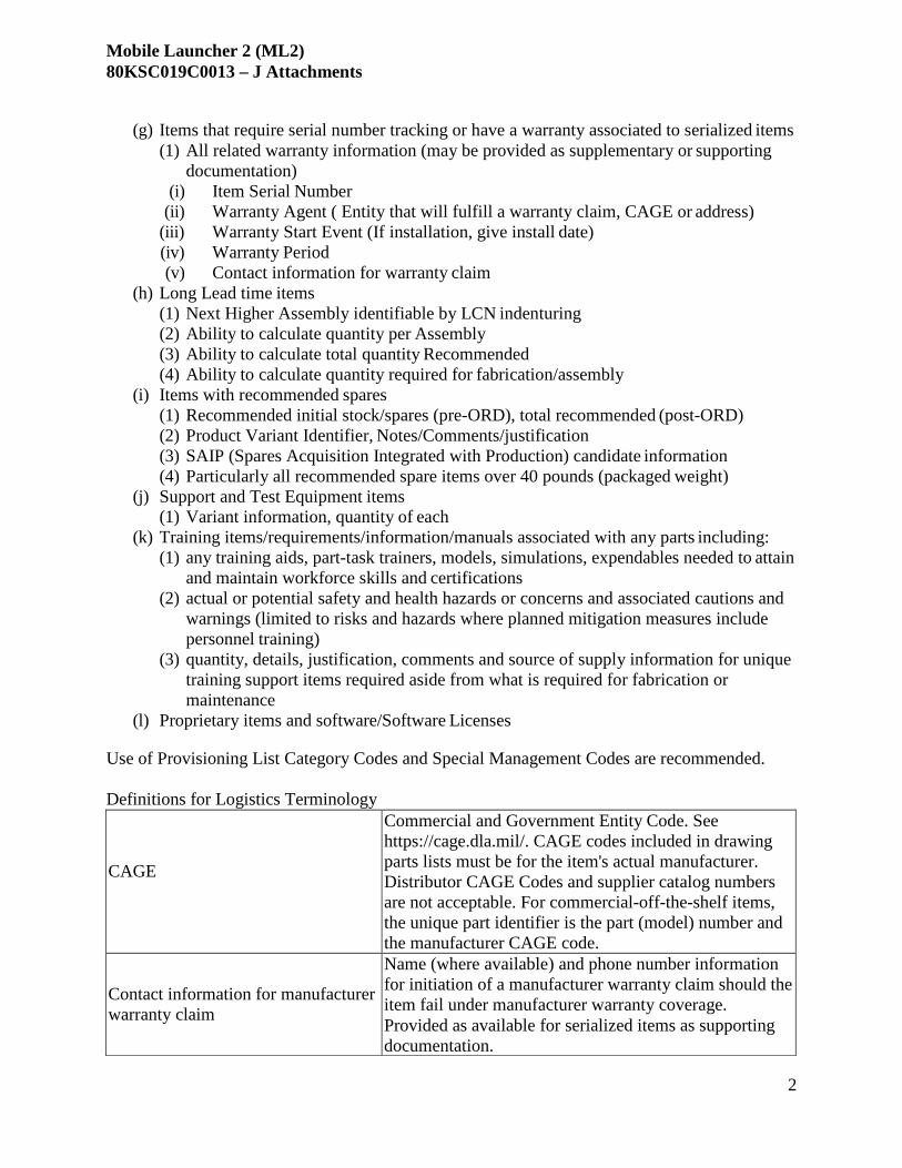
Mobile Launcher 2 (ML2) 80KSC019C0013 – J Attachments
2
(g) Items that require serial number tracking or have a warranty associated to serialized items (1) All related warranty information (may be provided as supplementary or supporting
documentation) (i) Item Serial Number
(ii) Warranty Agent ( Entity that will fulfill a warranty claim, CAGE or address) (iii) Warranty Start Event (If installation, give install date) (iv) Warranty Period (v) Contact information for warranty claim
(h) Long Lead time items (1) Next Higher Assembly identifiable by LCN indenturing (2) Ability to calculate quantity per Assembly (3) Ability to calculate total quantity Recommended (4) Ability to calculate quantity required for fabrication/assembly
(i) Items with recommended spares (1) Recommended initial stock/spares (pre-ORD), total recommended (post-ORD) (2) Product Variant Identifier, Notes/Comments/justification (3) SAIP (Spares Acquisition Integrated with Production) candidate information (4) Particularly all recommended spare items over 40 pounds (packaged weight)
(j) Support and Test Equipment items (1) Variant information, quantity of each
(k) Training items/requirements/information/manuals associated with any parts including: (1) any training aids, part-task trainers, models, simulations, expendables needed to attain
and maintain workforce skills and certifications (2) actual or potential safety and health hazards or concerns and associated cautions and
warnings (limited to risks and hazards where planned mitigation measures include personnel training)
(3) quantity, details, justification, comments and source of supply information for unique training support items required aside from what is required for fabrication or maintenance
(l) Proprietary items and software/Software Licenses Use of Provisioning List Category Codes and Special Management Codes are recommended.
Definitions for Logistics Terminology CAGE
Commercial and Government Entity Code. See https://cage.dla.mil/. CAGE codes included in drawing parts lists must be for the item's actual manufacturer. Distributor CAGE Codes and supplier catalog numbers are not acceptable. For commercial-off-the-shelf items, the unique part identifier is the part (model) number and the manufacturer CAGE code.
Contact information for manufacturer warranty claim
Name (where available) and phone number information for initiation of a manufacturer warranty claim should the item fail under manufacturer warranty coverage. Provided as available for serialized items as supporting documentation.

Mobile Launcher 2 (ML2) 80KSC019C0013 – J Attachments
3
Dimensions (Packaged) The cube information (length, width, height) of the item as it is packaged for storage.
Extended Price (Price for the total recommended quantity)
The estimated purchase price for the entire quantity recommended for purchase.
Hazardous Code
The Chemical Hazard Designation Code applicable to the material or chemical. This code will be included in the transportation environmental considerations narrative. Hazard codes are as follows: A - Radioactive B - Corrosive Basic Material C - Corrosive Acidic Material Da - Oxidizing Material (Acidic) Db - Oxidizing Material (Basic) E - Explosive Material F - Flammable/Combustible Material G - Compressed Gases M - Magnetic Material N - No Storage Hazard Requirements P - Organic Peroxides
Indenturing information
End Item Acronym, use of Logistics Support Analysis Control Number Indenture Code to accurately and comprehensively identify physical product structure at least down to the SRU level. Preferred LCN structure: “1123222221.”
Item Serial Number
A unique alphanumeric number assigned to an individual item that can be used to track the item's location, warranty status etc.
Item Useful Life (if limited)/wearout life
The amount of time a deteriorative item is allowed to remain in service before replacement is required. Also referred to as Limited Operational Life Item (LOLI). Also include relevant units.
Logistics Control Number (LCN)
A code that represents a functional or hardware generation breakdown/disassembly sequence of system/equipment hardware including support equipment, training equipment and installation hardware.
Long Lead Time Item Any item with a procurement or manufacturing lead time over 26 weeks.

Mobile Launcher 2 (ML2) 80KSC019C0013 – J Attachments
4
LRU (Line Replaceable Unit)
LRUs are items which are removed and replaced at the equipment’s location to restore the subsystem to an operationally ready condition in a timely manner. The selection of an LRU is based on the ability to detect the item’s failure, the item’s accessibility for removal/replacement tasks, and the ability to test/confirm the replacement of the item restores the functionality of the subsystem.
Maintenance Significant Item (MSI)
An item whose failure might have serious consequences for the safety and operation of the system. MSIs require corrective maintenance upon failure to return the system to operational condition. These can be designated with essentiality codes.
Part/item Name/Nomenclature An alphanumeric entry used to specify the name, model, or type of equipment being provisioned.
Part/reference Number
The alphanumeric entry assigned as an identifier of a particular part design. Its purpose is to simplify reference to that part. For commercial-off-the-shelf items, the vendor assigned model number is used as the part number.
Product Variant Identifier or Alternate LCN
Where model numbers are used as a part number, product variants are possible. This field is used to provide that information. An example would be a vendor that provides a number of isolation valves under the same base model number. Variant identifier information would be used to denote the specific configuration of that model number that is required.
Production (Procurement) Lead Time The amount of time that is required to either produce
organically or to procure an item and take delivery.
Quantity Per Assembly
The number of an item (part number and variant identifier) that are installed in the Next Higher Assembly by LCN indenturing
Quantity required for fabrication/assembly
The total quantity of an item required to complete fabrication of the end item (top level item) by LCN indenturing
S&TE Item/Part Number
The part number assigned to a specific item of support (S) or test equipment (TE) per appropriate use of support equipment documentation and identification number
SAIP Candidate
This will be appropriately documented for all items that are candidates for Spares Acquisition Integrated with Production
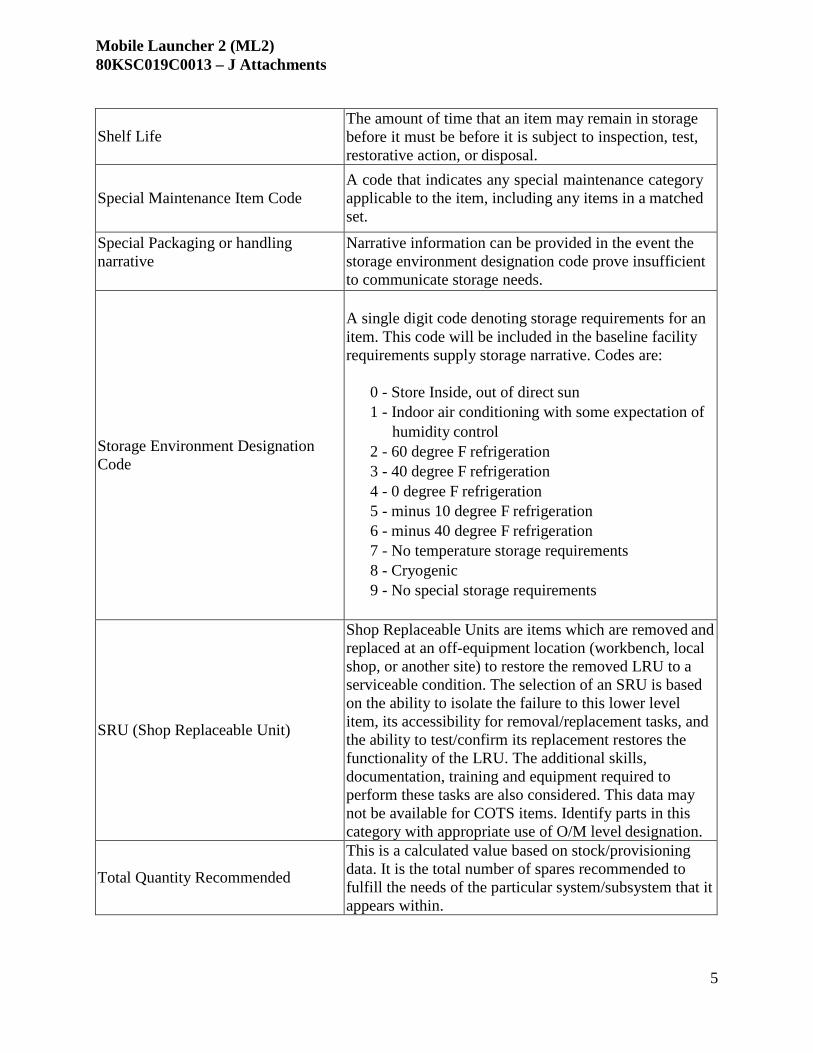
Mobile Launcher 2 (ML2) 80KSC019C0013 – J Attachments
5
Shelf Life
The amount of time that an item may remain in storage before it must be before it is subject to inspection, test, restorative action, or disposal.
Special Maintenance Item Code
A code that indicates any special maintenance category applicable to the item, including any items in a matched set.
Special Packaging or handling narrative
Narrative information can be provided in the event the storage environment designation code prove insufficient to communicate storage needs.
Storage Environment Designation Code
A single digit code denoting storage requirements for an item. This code will be included in the baseline facility requirements supply storage narrative. Codes are:
0 - Store Inside, out of direct sun 1 - Indoor air conditioning with some expectation of
humidity control 2 - 60 degree F refrigeration 3 - 40 degree F refrigeration 4 - 0 degree F refrigeration 5 - minus 10 degree F refrigeration 6 - minus 40 degree F refrigeration 7 - No temperature storage requirements 8 - Cryogenic 9 - No special storage requirements
SRU (Shop Replaceable Unit)
Shop Replaceable Units are items which are removed and replaced at an off-equipment location (workbench, local shop, or another site) to restore the removed LRU to a serviceable condition. The selection of an SRU is based on the ability to isolate the failure to this lower level item, its accessibility for removal/replacement tasks, and the ability to test/confirm its replacement restores the functionality of the LRU. The additional skills, documentation, training and equipment required to perform these tasks are also considered. This data may not be available for COTS items. Identify parts in this category with appropriate use of O/M level designation.
Total Quantity Recommended
This is a calculated value based on stock/provisioning data. It is the total number of spares recommended to fulfill the needs of the particular system/subsystem that it appears within.
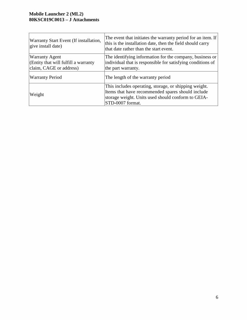
Mobile Launcher 2 (ML2) 80KSC019C0013 – J Attachments
6
Warranty Start Event (If installation, give install date)
The event that initiates the warranty period for an item. If this is the installation date, then the field should carry that date rather than the start event.
Warranty Agent (Entity that will fulfill a warranty claim, CAGE or address)
The identifying information for the company, business or individual that is responsible for satisfying conditions of the part warranty.
Warranty Period The length of the warranty period
Weight
This includes operating, storage, or shipping weight. Items that have recommended spares should include storage weight. Units used should conform to GEIA- STD-0007 format.

Mobile Launcher 2 (ML2) 80KSC019C0013 – J Attachments
1
ATTACHMENT J-6 – DESIGN PRODUCT DEFINITIONS/EXPECTATIONS The following products are required for each subsystem through design, construction, testing and turnover.
Product Maturity Definitions
P- Preliminary Preliminary - an initial version of the document which provides an overview of how the subject will be addressed and incorporated into the design.
U-Updated
Updated - the latest version of the document based on the existing maturity and level of detail in the design at the time of the indicated technical review. If previously baselined, the document should be revised and re-released following the technical review after incorporating any comments accepted during the technical review.
F- Final
Version of the document against which changes may be assessed and tracked. The document is submitted to the government following incorporation of comments from the 90% technical review.
Post Verification Testing
Final updates to affected engineering documentation representing as-built/as-verified/as-accepted subsystem/GSE configuration
Human Factors Assessment The HFEA is an assessment of the human interface aspects a system such as operator interaction, accessibility, work environment (heat, light, noise, etc.), controls and display interface, warning annunciation, and other factors utilized to derive the applicable human factors requirements to a given system based on the Federal Aviation Administration (FAA) Human Factors Design Standard (HFDS). The HFEA documents the relevant human factors criteria based on human interaction with the system and is updated as the project matures to indicate the evidence that each requirement has been verified at SAR/DCR.
MILESTONE MATURITY PRODUCT EXPECTATION
SRR N/A No product is expected.
Preliminary Integrated
Design
P The HFA should utilize the Human Factors Assessment Tool or a tailored version for the particular program or project. Known human/hardware interfaces should be listed, with a description of all associated issues. For each of the identified interface issues, the associated Federal Aviation Administration (FAA) Human Factors Design Standard (HFDS) or NASA-STD-3001/MIL-STD-1472 requirement, the type of activity (e.g. inspection, maintenance, off-nominal, etc.), the type of verification method, the consequence and the likelihood of a human error if not compliant, should be identified.
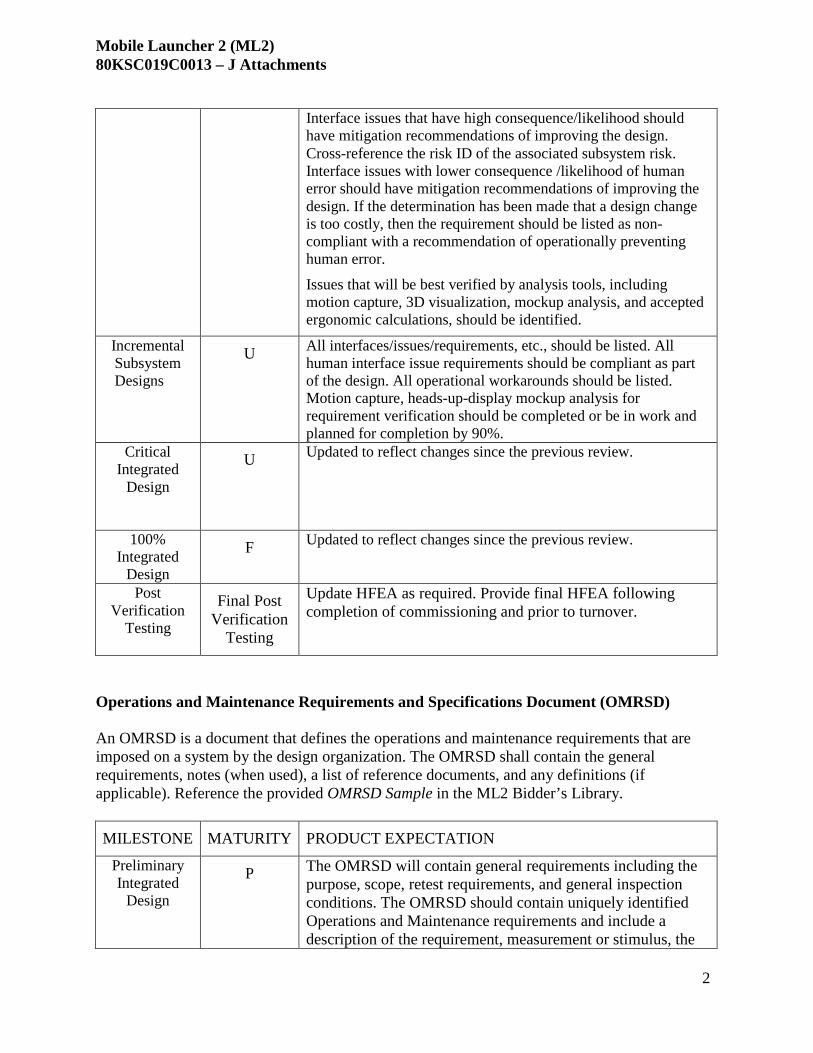
Mobile Launcher 2 (ML2) 80KSC019C0013 – J Attachments
2
Interface issues that have high consequence/likelihood should
have mitigation recommendations of improving the design. Cross-reference the risk ID of the associated subsystem risk. Interface issues with lower consequence /likelihood of human error should have mitigation recommendations of improving the design. If the determination has been made that a design change is too costly, then the requirement should be listed as non- compliant with a recommendation of operationally preventing human error.
Issues that will be best verified by analysis tools, including motion capture, 3D visualization, mockup analysis, and accepted ergonomic calculations, should be identified.
Incremental Subsystem Designs
U All interfaces/issues/requirements, etc., should be listed. All human interface issue requirements should be compliant as part of the design. All operational workarounds should be listed. Motion capture, heads-up-display mockup analysis for requirement verification should be completed or be in work and planned for completion by 90%.
Critical Integrated
Design
U Updated to reflect changes since the previous review.
100% Integrated
Design
F Updated to reflect changes since the previous review.
Post Verification
Testing
Final Post Verification
Testing
Update HFEA as required. Provide final HFEA following completion of commissioning and prior to turnover.
Operations and Maintenance Requirements and Specifications Document (OMRSD) An OMRSD is a document that defines the operations and maintenance requirements that are imposed on a system by the design organization. The OMRSD shall contain the general requirements, notes (when used), a list of reference documents, and any definitions (if applicable). Reference the provided OMRSD Sample in the ML2 Bidder’s Library.
MILESTONE MATURITY PRODUCT EXPECTATION
Preliminary Integrated
Design
P The OMRSD will contain general requirements including the purpose, scope, retest requirements, and general inspection conditions. The OMRSD should contain uniquely identified Operations and Maintenance requirements and include a description of the requirement, measurement or stimulus, the

Mobile Launcher 2 (ML2) 80KSC019C0013 – J Attachments
3
associated specification, interval, constraints and any other
pertinent remarks. The interval must be clearly communicated and contain enough information to determine whether the requirements apply to time periods of mission support, asset maintenance activities, and safe minimum level. The asset maintenance activities should ensure that the system continues to do what the users require in their present operating context. These requirements establish the safe minimum levels of maintenance to increase cost effectiveness. These requirements should address predictive maintenance, preventive restoration or replacement tasks, and detective maintenance tasks.
Incremental Subsystem Designs
U Any changes in the design since the prior technical review that drive changes to the OMRSD should be incorporated prior to the 60%. The asset maintenance activities and safe minimum level of maintenance should be complete at 60%. Comments accepted from the previous technical review should be incorporated prior to the 60%.
Critical Integrated
Design
U Any changes in the design since the prior technical review that drive changes to the OMRSD should be incorporated prior to the Integrated Critical Design Review. The OMRSD should identify all known requirements and be complete. The mission, asset maintenance activities, and safe minimum level of maintenance should be complete. Comments accepted from the previous technical review should be incorporated.
100% Integrated
Design
U Any changes in the design since the Integrated Critical Design review that drive changes to the OMRSD should be incorporated prior to the 100%. The OMRSD should identify all known requirements and be complete at the 100%. The mission, asset maintenance activities, and safe minimum level of maintenance should be complete. Comments accepted from the previous technical review should be incorporated prior to the 100%. Comments accepted from the Integrated Critical Design

Mobile Launcher 2 (ML2) 80KSC019C0013 – J Attachments
4
review should be incorporated. Incorporate into the Design data manual
Design Analysis Report An engineering analysis of a system’s technical characteristics and functional capability (e.g., design for mechanical loads and stress, thermal effects, electrical loads and transients). Design analyses may be performed using hand calculations or analysis software (i.e., finite element analysis). All inputs and groundrules and assumptions must be listed in the formal analysis report. The design analysis will address technical margins and the basis for establishment and acceptability of such margins. Analyses are performed by the design engineer. However, analyses may be delegated to a Lead Analyst. In all cases, an Analysis Summary Letter is due at the first design review and will summarize technical margins.
Content and format of the design analysis report will be in accordance with KSC-STD-Z-0015 and include, but not limited to:
(a) An executive summary, list of references, analysis discussion including problem and assumptions, analysis methods, analysis and supporting calculations (including hand calculations) and a summary
(b) A list of model input boundary conditions (e.g. pressure, temperature, material properties, loads, etc.) including all design, operational, modeling and code assumptions and ground rules
(c) A list of input conditions traceable to a documented reference source (ASME, NASA/KSC, ASCE, NIST, etc.).
(d) Native, or root, file input and output, and an image file (e.g. .pdf).
MILESTONE MATURITY PRODUCT EXPECTATION
Preliminary Integrated
Design
P The DAR will include Structural analysis to determine if structures can carry predicted loads within required factors/margins of safety, including:
• Determination of applicable structural requirements/factors of safety
• Determination of allowable stresses • Determination/calculation of loads (identification of
load cases) • Stress calculations for rough sizing of all components in
the critical load path (i.e., beams, trusses, fasteners, bolted joints, weldments, rollers, pins, etc.)
• Reaction forces at interfaces • Maximum allowable working pressures in vessels and
piping systems

Mobile Launcher 2 (ML2) 80KSC019C0013 – J Attachments
5
(2) Dynamic/kinematic analyses of moving
structures/components (3) System performance analysis to determine if critical performance requirements/criteria can be met, such as:
• Extend/retract times, required torque, actuator sizing, motor sizing
• Egress system speeds and accelerations • Flow rates, pressures, temperatures, fluid quality,
pump performance requirements, fluid system/vehicle interface requirements
The “final” configuration, geometry, loads, requirements, designer calculations, etc. will be locked in. This will serve as the basis for analysis. Analyses will be updated to reflect the final configuration. Designer calculations will be checked. An analysis summary will be written summarizing all analyses performed and all designer calculations checked, and will be incorporated into the design data manual. Analysis Summary:
• Summary Paragraph: brief summary of what was analyzed,
the results, and a statement regarding the ability of the design to meet applicable requirements.
• Analysis Approach: How analysis was done, applicable
requirements, factors of safety used, applicable codes or standards, etc.
• Loads: Brief description of loads and load cases considered
• Materials/Properties
• Design Calculations: Summary of design calculations
reviewed/checked. • Discussion/Results: Discussion of analysis results.
• References
In cases where both structural and fluids analyses will be performed (i.e. ML ECS system) two summaries may be published, one fluids, one structural.
Incremental Subsystem Designs
U Updated to reflect changes since the previous review.

Mobile Launcher 2 (ML2) 80KSC019C0013 – J Attachments
6
Critical Integrated
Design
U Updated to reflect changes since the previous review.
100% Integrated
Design
F Updated to reflect changes since the previous review. DAR will be incorporated into the design data manual
Design Data Manual The Design Data Manual includes historical data assembled during the course of the design work (as applicable). The Design Data Manual should be formatted in accordance with KSC-DF-107 and should include the following, at a minimum:
(a) All hand calculations, sketches, and other manually produced documentation will be scanned for electronic inclusion into the Design Data Manual.
(b) Project Description – Provide a general description of the overall project with a definitive description.
(c) Applicable Documents – List all codes, specifications, technical publications, and other documentation used in the design (many are already covered in the requirements/checklists).
(d) Historical Record – Document the changes/deletions/additions made during the design cycle. Include reference copies of Change Requests, Configuration Control Board Directives, etc.
(e) Design Philosophy – Document the design approach and the reasons for selecting (f) Design Considerations – Provide a description of all significant design parameters
selected. (g) Concept Sketches – Include working sketches of all concepts, whether selected or
not, that depict the functional flow, clearances, and tolerances required (may be in separate trade studies.
(h) Vendor Data – Catalog cuts information including any relevant correspondence with vendors.
(i) Calculations. Calculations maybe contained in a ―stand-alone analysis report that will be referenced in the data manual.
(j) Spares Parts List (may be a separate product).
(k) Investigations, Reports, Studies, Certifications. Long lead procurement items.
(l) Oxygen Compatibility Assessment (Ref. KSC-DE-512-SM, para. 6.3.1.3.2)
(m)Expansion Joint Installation Procedure
(n) Product Acceptance Test Plans

Mobile Launcher 2 (ML2) 80KSC019C0013 – J Attachments
7
(o) Cleaning Plan
(p) Packaging and Transportation Plan
MILESTONE MATURITY PRODUCT EXPECTATION
Preliminary Integrated
Design
P Develop initial preliminary design data manual.
Incremental Subsystem Designs
U Any changes in the design since the prior technical review that drive changes to the Design Data Manual should be incorporated prior to the 60%.
Critical Integrated
Design
U Any changes in the design since the prior technical review that drive changes to the Design Data Manual should be incorporated prior to the 90%.
100% Integrated
Design
F Comments accepted from the technical reviews should be incorporated and the document should be released following the review meeting.
Sneak Circuit Analysis A detailed system analysis to identify any unexpected path or logic flow within a system which, under certain conditions, can initiate an undesired function or inhibit a desired function. The path may consist of hardware, software, operator actions, or combinations of these elements. Sneak circuits are not the result of hardware failure but are latent conditions, inadvertently designed into the system, programmed into the software, or triggered by human error.
MILESTONE MATURITY PRODUCT EXPECTATION
Preliminary Integrated
Design
N/A No product is expected.
Incremental Subsystem Designs
P The submittal will include formal sneak circuit analysis or by demonstrating compliance with KSC-NE-10692, Electrical GSE Sneak Circuit Analysis Checklist and Design Guidelines

Mobile Launcher 2 (ML2) 80KSC019C0013 – J Attachments
8
and by completing form KSC-50-55 NS, Sneak Circuit Design
Checklist.
Critical Integrated
Design
U Updated to reflect changes since the previous review. The submittal will include formal sneak circuit analysis or by demonstrating compliance with KSC-NE-10692, Electrical GSE Sneak Circuit Analysis Checklist and Design Guidelines and by completing form KSC-50-55 NS, Sneak Circuit Design Checklist.
100% Integrated
Design
F Updated to reflect changes since the previous review. The submittal will include formal sneak circuit analysis or by demonstrating compliance with KSC-NE-10692, Electrical GSE Sneak Circuit Analysis Checklist and Design Guidelines and by completing form KSC-50-55 NS, Sneak Circuit Design Checklist.
Incorporate the Sneak Circuit Analysis into the design data manual
Operating Criteria The operating criteria captures all of the operational sequences required to assemble, operate and maintain the system as designed. The operating criteria must include any warning or redline limit values.
REVIEW MATURITY PRODUCT EXPECTATION
Preliminary Integrated
Design
N/A No product is expected.
Incremental Subsystem Designs
P The Operating Criteria should contain preliminary information for operating dependencies, major operations, component operations, control characteristics, reactive safing sequences and hardwire safing sequences.
Critical Integrated
Design
U Update to reflect changes since the previous review.

Mobile Launcher 2 (ML2) 80KSC019C0013 – J Attachments
9
100% Integrated
Design
F The Operating Criteria should contain final information for operating dependencies, major operations, component operations, control characteristics, reactive safing sequences and hardwire safing sequences.
Post Verification
Testing
Final Post Verification
Testing
Update Operating Criteria as required. Provide final Operating Criteria following completion of commissioning and prior to turnover.
Acceptance Data Package The Acceptance Data Package (ADP) consists of all of the engineering documentation required to produce the system. This includes all of the Engineering Products required in this Statement of Work (SOW), vendor catalog cuts, vendor or fabrication certification papers, personnel certifications, SDs, Deviations/Waivers, Open Items lists, and other documentation specifically identified in program requirements.
MILESTONE MATURITY PRODUCT EXPECTATION
Preliminary Integrated
Design
P An outline of all engineering documentation required to produce the system will be provided. Engineering documentation includes all of the Engineering Products that are applicable in this SOW, vendor catalog cuts, vendor or fabrication certification papers, personnel certifications, Material Usage Agreements, Deviations/Waivers, Open Items list, and other documentation specifically identified in this SOW. Components or subassemblies procured from vendors should be received with an ADP for products obtained through contract. This vendor ADP would become part of the overall ADP to be delivered completion of subsystem/GSE verification testing
Incremental Subsystem Designs
U Updated to reflect changes since the previous review.
Critical Integrated
Design
U Updated to reflect changes since the previous review.
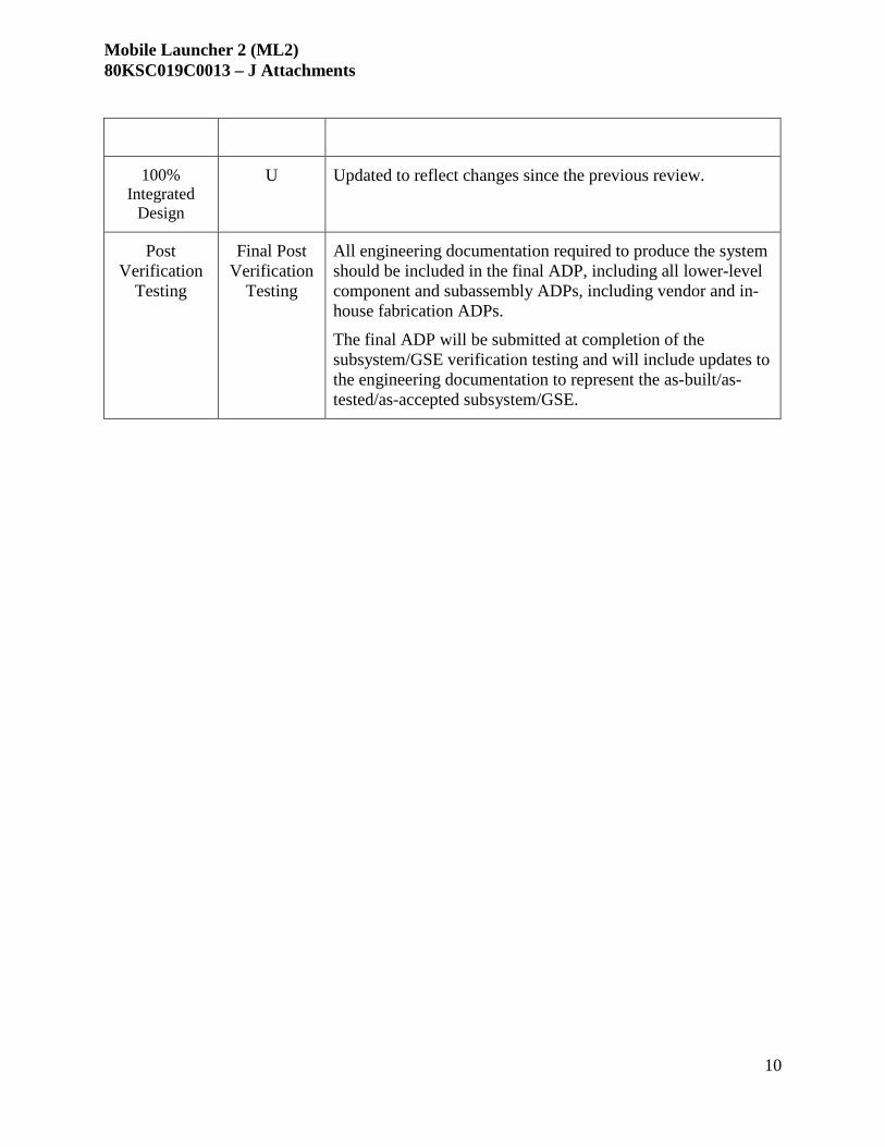
Mobile Launcher 2 (ML2) 80KSC019C0013 – J Attachments
10
100% Integrated
Design
U Updated to reflect changes since the previous review.
Post Verification
Testing
Final Post Verification
Testing
All engineering documentation required to produce the system should be included in the final ADP, including all lower-level component and subassembly ADPs, including vendor and in- house fabrication ADPs. The final ADP will be submitted at completion of the subsystem/GSE verification testing and will include updates to the engineering documentation to represent the as-built/as- tested/as-accepted subsystem/GSE.

Mobile Launcher 2 (ML2) 80KSC019C0013 – J Attachments
1
ATTACHMENT J-7 – GOVERNMENT FURNISHED EQUIPMENT (GFE)
Description Qty. WBS Reference Exploration Upper Stage Umbilical (EUSU) (K0000118209) 1 3.3.9 Vehicle Support Posts (VSP) (K0000093618) 8 3.3.13 KGCS EMSF 34620 (K0000077363) 1 3.5.2 KGCS Ethernet Distributor 37970 (K0000108440) 1 3.5.2 KGCS Fiber Optic Terminal 34610 (K0000072517) 1 3.5.2 KGCS Fiber Optic Terminal 34611 (K0000072523) 1 3.5.2 KGCS Fiber Optic Terminal 34619 (K0000072527) 1 3.5.2 KGCS LCD 34614 (K0000068707) 1 3.5.2 KGCS LCD 34615 (K0000072501) 1 3.5.2 KGCS LCD 34616 (K0000072505) 1 3.5.2 KGCS LCD 34617 (K0000072509) 1 3.5.2 KGCS LCD 34618 (K0000072513) 1 3.5.2 KGCS Primary Comm. Rack 34612 (K0000061139) 1 3.5.2 KGCS Secondary Comm. Rack 34613 (K0000068704) 1 3.5.2 MPDI Interface 34621 (K0000102894) 1 3.5.2

Mobile Launcher 2 (ML2) 80KSC019C0013 – J Attachments
1
ATTACHMENT J-8 - HANDLING AND ACCESS
Handling and Access (H&A) Equipment List (Section 3.3) * Indicates equipment with direct interfaces to the ML
(a) *Core Stage Engine Service Platform - The Core Stage Engine Service Platform (CS
ESP) is located in the exhaust hole and supported by the Mobile Launcher just below the blast shield on zero level. The CS ESP is located under the Core Stage main engines. The CS ESP will provide nominal service operations at the aft section of the Core Stage at the VAB and LC39B. The CS ESP is capable of supporting additional tooling used for nominal operations such as a man lift. Reference K0000110629, Aft Core and Main Engines H&A Equipment Installation, drawing.
(b) *Booster Engine Service Platforms - The Booster Engine Service Platforms (Booster ESPs) are located in the exhaust hole and are supported by the Mobile Launcher (ML) just below the blast shield on zero level. There will be a total of two Booster ESPs, placing one at each Booster location. The Booster ESP will support access needs on the aft end of the Booster at the VAB and LC39B. The Booster ESP will also provide support to other Handling and Access equipment on ML zero deck for vehicle processing. Reference K0000093615, Engine Service Platform, Booster Installation, drawing.
(c) Engine Vertical Installer - The Engine Vertical Installer (EVI) tool is used to remove and install the RS-25 engines in the Core Stage. The tool is used in conjunction with the EVI platform. Engine replacement operations take place while the ML and vehicle are in the Vehicle Assembly Building.
(d) *Engine Vertical Installer Platforms - EVI Platform is used for EVI operations and provides positioning of EVI tool via V-track in the Vertical Assembly Building. Platform is accessed from ML-0 level via ladders. Reference K0000111015, Engine Vertical Installer H&A Equipment Installation, drawing.
(e) *TSMU Access Platforms - The TSMU Access Platforms provide a means of access to the LH2 and LO2 Tail Service Mast Umbilicals for installation and inspection operations. TSMU Access Platforms also provide access to the Core Stage forward looking cameras for inspection and cleaning as well as access to the Core Aft Restraint Z-axis Strut and interface bracket. The TSMU Access Platforms are comprised of two sets of work stands plus a winch and ramp system used to transport the platforms to their designated position on top of the ML blast shields. Reference K0000110686, Tail Service Mast Umbilical H&A Equipment Installation; K0000110695 ML Surface Tie-Down Layout drawings.
(f) Engine Service Platform Transporter - Provides a means to transport the Booster and Core Stage (CS) Engine Service Platforms (ESPs) and related equipment between the Mobile Launcher (ML) and the storage location on the pad slope.
(g) *Vehicle Support Post Access - The Vehicle Support Post (VSP) handling and access will support the installation and removal of the VSP blast shields. Commercial off-the- shelf (COTS) work platforms will be used for worker access to the heat shield on top of the VSP. Jib hoists placed behind the VSP will support handling operations of the VSP

Mobile Launcher 2 (ML2) 80KSC019C0013 – J Attachments
2
blast shield. VSP handling and access operations will be performed at the VAB and LC39B. Reference K0000073862, Vehicle Support Post Access Installation, drawing.
(h) SRB TVC Access Platform - The SRB TVC Access Platform is a portable set of platforms that provide access to the Booster TVC system in the area of the aft skirt. There is a set of platforms for the left and right boosters; each separates into smaller section for ease of transport. The platforms are secured to the Booster ESPs with fasteners that are captive to the TVC access platforms.
(i) RS-25 Man lift - The RS-25 man lift will be operated on the lower level of the Core ESP and will provide a single person access to the interior of the RS-25 engine nozzles for installation and removal of the throat plug and for inspection and repair of the interior surfaces. The man lift is self-propelled and has a powered lift. Upper controls are on a pendent so that the machine can be operated from the basket or from the ground. It will be necessary to operate the machine from the ground due to the low overhead steel of the Core ESP and the low hanging engine nozzles.

Mobile Launcher 2 (ML2) 80KSC019C0013 – J Attachments
1
ATTACHMENT J-9 - GLOSSARY OF TERMS/ACRONYM LIST
Term Definition 1B 1B represents “Block 1B” which is the second version of the SLS vehicle with EUS 3D three-dimensional A2LA American Association for Laboratory Accreditation AASHTO American Association of State Highway and Transportation Officials AC alternating current ACO Administrative Contracting Officer ADP Acceptance Data Package A-E Architect-Engineer AFB Award Fee Board AHJ Authority Having Jurisdiction ANSI American National Standards Institute AOE Area of Emphasis API American Petroleum Institute Ar Argon ASCE American Society of Civil Engineers ASD Accumulation Start Date ASEU Aft Skirt Electrical Umbilical ASME American Society of Mechanical Engineers ASPU Aft Skirt Pneumatic Umbilical ASTM American Society for Testing and Materials ATP Authority to Proceed BAIR Breathing Air BCT Basic Cost Template BOE Basis of Estimate BOLE Booster Obsolescence Life Extension BOM bill of material BOSS Base Operations and Spaceport Services BPVC Boiler and Pressure Vessel Code C&D Construction and Demolition C3 Command, Control and Communications CAA Crew Access Arm CAD Computer Aided Design CAGE Contractor and Government Entity CAIR Compressed Air CAS Certified Accounting System CCAFS Cape Canaveral Air Force Station CCB Change Control Board CDR Critical Design Review CER Cost Estimating Relation CFO Chief Financial Officer C.F.R. Code of Federal Regulations CG center of gravity CGHe Cold Gaseous Helium CIAO Central Industry Assistance Office CM Configuration Management COM Cost of Money COMM Communications ConOps Concept of Operations COR Contracting Officer’s Representative

Mobile Launcher 2 (ML2) 80KSC019C0013 – J Attachments
2
COTS Commercial Off the Shelf CPA Certified Public Accountant CPAF Cost Plus Award Fee CPM Critical Path Method CPR Contract Performance Report CPR Contract Performance Report CQC Contractor Quality Control CRMS Central Radio Monitoring System CS Core Stage CSFSU Core Stage Forward Skirt Umbilical CSI Construction Specification Institute CSITU Core Stage Inter-Tank Umbilical CT Crawler Transporter CUI Compact Unique Identifier CWBS Contract Work Breakdown Structure CxA Commissioning Authority DAR Design Analysis Report DARCY Diverted Aggregate Recycling and Collection Yard DC direct current DCAA Defense Contract Audit Agency DCMA Defense Contract Management Agency DCR Design Certification Review DEP Department of Environmental Protection DOD Department of Defense DOF degrees of freedom DOL Department of Labor DOR Designer of Record DOT Department of Transportation DPAS Defense Priorities and Allocations System DUNS Data Universal Numbering System DVM Design Verification Matrix DW Deviation Waiver EAB Environmental Assurance Branch EAR Export Administration Regulations ECS Environmental Control System EES Emergency Egress System EGS Exploration Ground Systems EIA Electronic Industries Alliance EMCD Electromechanical Control Diagram EMSF Emergency Safing EO Engineering Order EPA Environmental Protection Agency EPCRA Emergency Planning and Community Right-To-Know Act EPOC Environmental Point of Contact ER Eastern Range ESP Engine Service Platform ETXS Ethernet Transmission System EUS Exploration Upper Stage EUSU Exploration Upper Stage Umbilical EVI Engine Vertical Installer EVM Earned Value Management EVMS Earned Value Management System FAA Federal Aviation Administration

Mobile Launcher 2 (ML2) 80KSC019C0013 – J Attachments
3
FAR Federal Acquisition Regulation FDEP Florida Department of Environmental Protection FDO Fee Determination Official FDS Fire Detection System FHX Flight-to-Ground Heat Exchanger FSC Federal Supply Classification FSS Fire Suppression System FSS Flight Safety System FTS Flight Termination System G&A General and Administrative GAO Government Accountability Office GCS Ground Cooling System GFE Government Furnished Equipment GFY Government Fiscal Year GH2 Gaseous Hydrogen GHe Gaseous Helium GIS Ground Interface Schematic GIS Geographical Information System GMPS Ground Main Propulsion System GN2 Gaseous Nitrogen GO2 Gaseous Oxygen GPS Global Positioning System GS Ground Systems GSA Government Services Administration GSDO Ground Systems Development and Operations GSE Ground Support Equipment GSP-GSE Ground Special Power - Ground Support Equipment GSP-VEH Ground Special Power - Vehicle H&A Handling and Access H2 Hydrogen HAASP Hydraulic Arms and Accessories Service Pressure System HBOI Hydrogen Burn-Off Igniters HCU Hydraulic Control Accumulators HD High Definition He Helium HF Human Factors HFDS Human Factors Design Standard HFEA Human Factors Engineering Assessment HGLDS Hazardous Gas Leak Detection Subsystem HMI Human Machine Interface HPU Hydraulic Power Unit HR Hour HVAC Heating Ventilation and Air Conditioning HWDIP Hazardous Waste Determination In Progress Hyper Hypergols Hz Hertz ICD Interface Control Document ICPSU Interim Cryogenic Propulsion Stage Umbilical ICS Industrial Control Systems IDP Interface Detail Products IMS Integrated Master Schedule IOPSS Ignition Overpressure and Sound Suppression IOZ inorganic zinc

Mobile Launcher 2 (ML2) 80KSC019C0013 – J Attachments
4
IPMR Integrated Performance Measurement Report IPO Industrial Property Officer ISC Institutional Support Contract IT Information Technology ITAR International Traffic in Arms Regulations ITD inception-to-date JHA Job Hazard Analysis KCCS Kennedy Complex Control System KGCS Kennedy Ground Control System KITS Kennedy Integrated Transmission System KLXS Kennedy LX Support Services KSC Kennedy Space Center LAS Launch Abort System LC Labor Classification LC39B Launch Complex 39B LCC Launch Control Center LCN Logistics Control Number LCS Launch Control Subsystem LETF Launch Equipment Test Facility LH2 Liquid Hydrogen LISS Lightning Instrumentation Subsystem LMRDAS Land Mobile Radio Distributed Antenna System LN2 Liquid Nitrogen LO2 Liquid Oxygen LOLI Limited Operational Life Item LRS Launch Release System LRU Line Replaceable Unit Major Sub A major subcontractor is defined as having a total proposed value greater than or equal to 10%
of the total proposed cost, excluding subcontractors only providing material and Commercial Off the Shelf (COTS) items.
MIP Mandatory Inspection Point MISS Meteorological Instrumentation Subsystem ML1 Mobile Launcher 1 ML2 Mobile Launcher 2 MLS Mobile Launcher Structure MPDI Mobile Launcher Physical Data Interface MPS Main Propulsion System MSDS Material Safety Data Sheet MSI Maintenance Significant Item MSS Manufacturing Standardization Society N/A non-applicable N2 Nitrogen N2H4 Hydrazine NACE National Association of Corrosion Engineers NAICS North American Industry Classification System NASA National Aeronautics and Space Administration NBIC National Board Inspection Code NCS National Consensus Standard NDIA National Defense Industrial Association NDT Nondestructive Testing NEMA National Electrical Manufacturers Association NESS NF 1018 Electronic Submission System NF NASA Form

Mobile Launcher 2 (ML2) 80KSC019C0013 – J Attachments
5
NFPA National Fire Protection Association NFS NASA FAR Supplement NIIN National Item Identification Number NIST National Institute of Standards and Technology NPD NASA Procedural Directive NPR NASA Procedural Requirement NRACM Non-Regulated Asbestos Containing Materials NSSC NASA Shared Services Center NTP Notice to Proceed NTSC National Television System Committee NVLAP National Voluntary Laboratory Accreditation Program O&M Operations and Maintenance O/T Overtime O2 Oxygen OCE Other Cost Elements ODC Other Direct Costs ODMS Oxygen Deficiency Monitoring System OIS Operational Intercommunication System OIS-M Operational Intercommunication System - Move OMRSD Operations and Maintenance Requirements and Specifications Document ORD Operational Readiness Date OS Organic Solvents OSHA Occupational Safety and Health Administration OSMU Orion Service Module Umbilical OT Operational Technology OTB Over Target Baseline OTN Optical Transport Network OTS Over Target Schedule OV Operational Video PAS Payload Accommodation Subsystem PAWS Paging/Area Warning System PCB Polychlorinated biphenyl PDR Preliminary Design Review PE Professional Engineer PES Performance Evaluation Score PHS&T Packaging, Handling, Storage & Transportation PLC Programmable Logic Controller POC Point of Contact POCS II Photo Optical Control System II PPE Personal Protective Equipment PTC Parametric Technology Corporation PVS Pressure Vessel System PWQ Process Waste Questionnaire QA Quality Assurance QPL Qualified Parts List RC Reporting Category RCRA Resource Conservation and Recovery Act REC Record of Environmental Consideration REPP Relevant Experience and Past Performance RF Radio Frequency RFI Request for Information RFP Request for Proposals RFQ Request for Qualifications

Mobile Launcher 2 (ML2) 80KSC019C0013 – J Attachments
6
RFTS Radio Frequency and Telemetry Subsystem RIO Remote Input/Output RMA Reliability, Maintainability and Availability RSCS Range Safety and Checkout Subsystem RTS Range Tracking System S&TE Support and Test Equipment S/T Sick Time SAA Satellite Waste Accumulation Area SAIP Spares Acquisition Integrated with Production SAM System for Award Management SAR System Acceptance Review SCADA Supervisory Control and Data Acquisition SCAPE Self-Contained Atmospheric Protective Ensemble SCCS Spaceport Command and Control System SD Submittal Documents SDAS Sensor Data Acquisition Subsystem SEMO Supply and Equipment Management Officer SLS Space Launch System SME Subject Matter Expert SMS System Mechanical Schematic SOW Statement of Work SRM Solid Rocket Motor SRU Shop Replaceable Unit SSA Source Selection Authority T&CD Timing and Countdown TAT Threat Assessment Team TBD To Be Determined TCLP Toxicity Characteristic Leaching Procedure TCS Thermal Control Subsystem THSS TVC Hydraulic Servicing System TIM Technical Interchange Meeting TOSC Test Operations and Support Contract TRP Total Recycling Program TSMU Tail Service Mast Umbilical TVC Thrust Vector Control Systems UL Underwriters Laboratories UPS Uninterruptable Power Supply UW Universal Wastes VAB Vehicle Assembly Building VC visually clean VDS Vehicle Damper System VJ Vacuum Jacketed VOC Volatile Organic Compounds VoIP Voice over Internet Protocol VS Vehicle Stabilizer VSP Vehicle Support Posts VSS Vehicle Stabilization Subsystem WAP Wireless Access Point WBS Work Breakdown Structure WDR Wet Dress Rehearsal Working Days Monday through Friday, excluding all Federal Holidays Wx Weather Instrumentation WYE Work Year Equivalent

Mobile Launcher 2 (ML2) 80KSC019C0013 – J Attachments
1
ATTACHMENT J-10 – COMPLIANCE DOCUMENTS
Document Number Document Name Cited Location 29 C.F.R. § 1910 OSHA Laws & Regulations J-1: 1.3,
3.2.1.1, J-3-2
29 C.F.R. § 1926 Safety and Health Regulations for Construction
J-3-2
40 C.F.R. § 260 Hazardous Waste Management System: General
J-3-13
40 C.F.R. § 261 Identification and Listing of Hazardous Waste
J-3-13
40 C.F.R. § 265 Interim Status Standards for Owners and Operators of Hazardous Waste Treatment, Storage, and Disposal Facilities
J-3-13
40 C.F.R. § 268 Land Disposal Restrictions J-3-13 40 C.F.R. § 273 Standards for Universal Waste
Management J-3-13
40 C.F.R. § 279 Standards for the Management of Used Oil
J-3-13 J-3-22
40 C.F.R. § 761 PCB Manufacturing, Processing, Distribution in Commerce, and Use Prohibitions
J-3-13
AC 70/7460-1L FAA Obstruction Marking and Lighting
J-1: 3.6.1, J-3-5
AS9100 Quality Systems-Model for Quality Assurance in Production, Installation, and Serving
E.4
ASHRAE 62.1 Standards for Ventilation and Indoor Air Quality
J-1: 3.6.6
ASME A17.1 Safety Code for Elevators and Escalators
J-1: 3.6.3
ASME A17.2 Guide for Inspection of Elevators, Escalators, and Moving Walks
J-1: 3.6.3
ASME A17.3 Safety Code for Existing Elevators and Escalators
J-1: 3.6.3
ASME B31.3 Process Piping Guide J-1: 3.2.3, 3.2.12, 3.2.13, 3.6.2
ASTM A312 Standard Specification for Seamless, Welded, and Heavily Cold Worked Austenitic Stainless Steel Pipes
J-1: 3.2.3, 3.2.12, 3.2.13
CSA B44 Safety Code for Elevators and Escalators
J-1: 3.6.3
DI-MGMT-81861A Data Item Description Report DRD 1.0-6 ENG-I-MP07 Utility Locate/Excavation Permit
Procedure J-3-1
GEIA-STD-0007 Logistics Product Data J-5 GSDO-ICD-1246 KGCS ICD J-1: 3.5.2 GSDO-ICD-1250 Element to Element ICD J-1: 3.1,

Mobile Launcher 2 (ML2) 80KSC019C0013 – J Attachments
2
3.2.3,
3.2.12, 3.2.13, 3.6.6
GSDO-PLN-1044 Reliability, Maintainability, Availability Requirements
J-1: 3.1.3
GSDO-SPEC-1134 Compact Unique Identifier Definition Specification
J-1: 3.5
IEST-RP-CC034.4 HEPA and ULPA Filter Leak Tests J-1: 3.2.4 ISO 14952 Space Systems – Surface
Cleanliness of Fluid Systems J-1: 3.2.3, 3.2.12, 3.2.13
ISO-14644-3 Cleanrooms and Associated Controlled Environments
J-1: 3.2.4
K00000334071 VS DVM J-1: 3.3.3 K0000058774 CAA Cable Interconnect Diagram J-1: 3.3.8 K0000059132 OSMU Cable Interconnect Diagram J-1: 3.3.11 K0000063242 THSS DVM J-1: 3.2.14 K0000064182 CSITU Block Diagram and
Schematic J-1: 3.3.7
K0000064617 ASEU Cable Interconnect Diagram J-1: 3.3.4 K0000064618 ASEU Cable Interconnect Diagram J-1: 3.3.4 K0000064619 ASEU Cable Interconnect Diagram J-1: 3.3.4 K0000064620 ASEU Cable Interconnect Diagram J-1: 3.3.4 K0000065432 TSMU Installation Drawing J-1: 3.3.12 K0000065434 TSMU Installation Drawing J-1: 3.3.12 K0000067124 TSMU Cable Interconnect Diagram J-1: 3.3.12 K0000067630 CSFSU Cable Interconnect
Diagram J-1: 3.3.6
K0000068960 CSITU Cable Interconnect Diagram J-1: 3.3.7 K0000068962 CSFSU Block Diagram and
Schematic J-1: 3.3.6
K0000073862 Vehicle Support Post Access Installation
J-1: 3.3.10, J-8
K0000074337 Engine Service Platform Hoist Installation
J-1: 3.3.10,
K0000093615 Engine Service Platform, Booster Installation
J-1: 3.3.10, J-8
K0000102252 OSMU Block Diagram and Schematic
J-1: 3.3.11
K0000110629 Aft Core and Main Engines H&A Equipment Installation
J-1: 3.3.10, J-8
K0000110686 Tail Service Mast Umbilical H&A Equipment Installation
J-1: 3.3.10, J-8
K0000110695 ML Surface Tie-Down Layout drawings
J-8
K0000111015 Engine Vertical Installer H&A Equipment Installation
J-1: 3.3.10, J-8
K0000120111 CAA Block Diagram and Schematic
J-1: 3.3.8
K0000120859 ASEU Concept of Operations J-1: 3.3.4 K0000124236 EUSU Cable Interconnect Diagram J-1: 3.3.9 K0000130758 VSP DVM J-1: 3.3.13

Mobile Launcher 2 (ML2) 80KSC019C0013 – J Attachments
3
K0000132285-PLN VSP Concept of Operations J-1: 3.3.13 K0000135886 TSMU Concept of Operations J-1: 3.3.12 K0000136831 CSITU Concept of Operations J-1: 3.3.7 K0000137328 TSMU DVM J-1: 3.3.7 K0000137470 CSITU DVM J-1: 3.3.7 K0000139365 ASEU DVM J-1: 3.3.4 K0000141047 OSMU Cable Interconnect Diagram J-1: 3.3.11 K0000144690-GEN IOPSS DVM J-1: 3.6.7 K0000147452 CSFSU Concept of Operations J-1: 3.3.6 K0000147458 CSFSU DVM J-1: 3.3.6 K0000154241 ASPU Concept of Operations J-1: 3.3.5 K0000175145 ASPU DVM J-1: 3.3.5 K0000244893-GEN H&A DVM J-1: 3.3.10 K0000283895-SPC SLS Mobile Launcher Structure
Random Vibration Environment J-1: 3.1
K0000331775-GEN TCS DVM J-1: 3.4.10 K0000332564-GEN GCS Concept of Operations J-1: 3.2.8 K0000332767 HGLDS DVM J-1: 3.4.4 K0000332788-GEN RSCS DVM J-1: 3.4.8 K0000332933 MLS DVM J-1: 3.3.1 K0000333825-GEN RFTS DVM J-1: 3.4.7 K0000334016 OSMU DVM J-1: 3.3.11 K0000334932 EES Concept of Operations J-1: 3.3.2 K0000335385-PLN LRS Concept of Operations J-1: 3.4.5 K0000335596 GSP-GSE DVM J-1: 3.4.2 K0000335597 GSP-VEH DVM J-1: 3.4.3 K0000335602-GEN LRS DVM J-1: 3.4.5 K0000335615-GEN SDAS DVM J-1: 3.4.9 K0000335816 CAA Concept of Operations J-1: 3.3.8 K0000335821 OSMU Concept of Operations J-1: 3.3.11 K0000336033 EUSU DVM J-1: 3.3.9 K0000336035-GEN CAA DVM J-1: 3.3.8 K0000344876-GEN GCS DVM J-1: 3.2.8 K0000346149-GEN ECS DVM J-1: 3.2.4 K0000346151-GEN BAIR DVM J-1: 3.2.2 K0000346240-GEN GHe DVM J-1: 3.2.5 K0000346250-GEN GN2 DVM J-1: 3.2.6 K0000346252-GEN GO2 DVM J-1: 3.2.7 K0000346351 Hyper DVM J-1: 3.2.11 K0000346839-GEN Wx DVM J-1: 3.4.11 K0000348397-GEN LH2 DVM J-1: 3.2.12 K0000348401-GEN LO2 DVM J-1: 3.2.13 K0000348705-SPC Specification for SLS Mobile
Launcher Design Loads J-1: 3.1.2.1
K0000348800 HAASP DVM J-1: 3.2.10 K0000349423-GEN 60 Hz DVM J-1: 3.6.1 K0000349848-GEN HVAC DVM J-1: 3.6.6 K0000349857-GEN KCCS DVM J-1: 3.6.8 K0000349865-GEN ODMS DVM J-1: 3.6.9 K0000349867-GEN FSS DVM J-1: 3.6.5 K0000349869-GEN FDS DVM J-1: 3.6.4 K0000349871-GEN CAIR DVM J-1: 3.6.2 K0000349873-GEN Potable Water DVM J-1: 3.6.10

Mobile Launcher 2 (ML2) 80KSC019C0013 – J Attachments
4
K0000349875-GEN Elevator DVM J-1: 3.6.3 K0000349877-GEN Septic Wastewater DVM J-1: 3.6.11 K0000349942 EUSU Concept of Operations J-1: 3.3.9 K0000350417-GEN PAS DVM J-1: 3.4.6 K0000352106 EUSU Block Diagram and
Schematic J-1: 3.3.9
K0000352107 EUSU Block Diagram and Schematic
J-1: 3.3.9
K0000355110 GMPS DVM J-1: 3.2.9 K0000363764 KGCS DVM J-1: 3.5.2 K0000369449 EES DVM J-1: 3.3.2 KDP-KSC-P-2402 Award Fee Evaluation Process J-13 DELETED KNPD 1600.3 Use of Alcoholic Beverages on
Kennedy Space Center (KSC) Property
H.5
KNPD 1810.1 KSC Occupational Medicine Program
H.5
KNPR 1600.1 KSC Security Procedural Requirements
H.5
KNPR 1840.19 KSC Industrial Hygiene Programs J-3-1 KNPR 1860.1 KSC Ionizing Radiation Protection
Program H.5
KNPR 1860.2 KSC Nonionizing Radiation Protection Program
H.5
KNPR 4000.1 Supply and Equipment System Manual
G.5, H.5
KNPR 6000.1 KSC Transportation Support System Manual
H.5
KNPR 8500.1 KSC Environmental Management Requirements
H.5, J-3-13, J-3-22, J-10
KNPR 8715.2 Comprehensive Emergency Management Plan (CEMP)
H.5
KNPR 8715.3 KSC Safety Procedural Requirements
H.5, J-10
KNPR 8715.7 KSC Construction Contractor Safety and Health Practices Procedural Requirements
H.5, DRD 1.0-2,
DELETED KNPR 8830.1 Facility Asset Management
Procedural Requirements H.5
KSC-DD-804 KCCS Design Guide J-1: 3.6.8 KSC-DE-512-SM Facility Systems, Ground Support
Systems, and Ground Support Equipment General Design Requirements
J-1: 3.1.2.1, 3.1.2.2, 3.1.4, 3.1.6.2 3.2.1.1, 3.2.3
KSC-DF-107 Technical Documentation Style Guide
J-6, J-10
KSC-GP-435 Engineering Drawing Practices J-1: 3.1.7
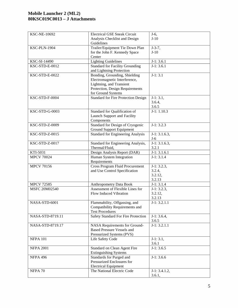
Mobile Launcher 2 (ML2) 80KSC019C0013 – J Attachments
5
KSC-NE-10692 Electrical GSE Sneak Circuit Analysis Checklist and Design Guidelines
J-6, J-10
KSC-PLN-1904 Trailer/Equipment Tie Down Plan for the John F. Kennedy Space Center
J-3-7, J-10
KSC-SI-14490 Lighting Guidelines J-1: 3.6.1 KSC-STD-E-0012 Standard for Facility Grounding
and Lightning Protection J-1: 3.6.1
KSC-STD-E-0022 Bonding, Grounding, Shielding Electromagnetic Interference, Lightning, and Transient Protection, Design Requirements for Ground Systems
J-1: 3.1
KSC-STD-F-0004 Standard for Fire Protection Design J-1: 3.1, 3.6.4, 3.6.5
KSC-STD-G-0003 Standard for Qualification of Launch Support and Facility Components
J-1: 1.10.3
KSC-STD-Z-0009 Standard for Design of Cryogenic Ground Support Equipment
J-1: 3.2.3
KSC-STD-Z-0015 Standard for Engineering Analysis J-1: 3.1.6.3, J-6
KSC-STD-Z-0017 Standard for Engineering Analysis, Thermal/Fluid,
J-1: 3.1.6.3, 3.2.1
KTI-5031 Design Analysis Report (DAR) J-1: 3.1.6.1 MPCV 70024 Human System Integration
Requirements J-1: 3.1.4
MPCV 70156 Cross Program Fluid Procurement and Use Control Specification
J-1: 3.2.3, 3.2.4, 3.2.12, 3.2.13
MPCV 72585 Anthropometry Data Book J-1: 3.1.4 MSFC 20M02540 Assessment of Flexible Lines for
Flow Induced Vibration J-1: 3.2.3, 3.2.12, 3.2.13
NASA-STD-6001 Flammability, Offgassing, and Compatibility Requirements and Test Procedures
J-1: 3.2.1.1
NASA-STD-8719.11 Safety Standard For Fire Protection J-1: 3.6.4, 3.6.5
NASA-STD-8719.17 NASA Requirements for Ground- Based Pressure Vessels and Pressurized Systems (PVS)
J-1: 3.2.1.1
NFPA 101 Life Safety Code J-1: 3.1, 3.6.1
NFPA 2001 Standard on Clean Agent Fire Extinguishing Systems
J-1: 3.6.5
NFPA 496 Standards for Purged and Pressurized Enclosures for Electrical Equipment
J-1: 3.6.6
NFPA 70 The National Electric Code J-1: 3.4.1.2, 3.6.1,

Mobile Launcher 2 (ML2) 80KSC019C0013 – J Attachments
6
3.6.4, NFPA 72 National Fire Alarm and Signaling
Code J-1: 3.6.4
NFPA 780 Standard for the Installation of Lightning Protection Systems
J-1: 3.6.1
NIST 800-53 Recommended Security Controls for Federal Information Systems and Organizations
J-1: 3.5.1
NPD 1600.3 Policy on Prevention of and Response to Workplace Violence
H.5, H.7
NPD 8800.14 Policy for Real Property Management
G.8
NPR 1600.4A Identity and Credential Management
H.5
NPR 2810.1 Security of Information Technology J-1: 3.5.1 NPR 4100.1 NASA Materials Inventory
Management Manual G.5
NPR 4200.1 NASA Equipment Management Procedural Requirements
G.5
NPR 4300.1 NASA Personal Property Disposal Procedural Requirements
G.5
NPR 8831.2 Facility Maintenance Management G.8 DELETED REC-10345 ML2 Record of Environmental
Consideration J-1: 1.4
SLS-ICD-052 Space Launch System Program-to- Ground Systems Development And Operations Program ICD
J-1: 3.1, 3.2.3, 3.4.5,

Mobile Launcher 2 (ML2) 80KSC019C0013 – J Attachments
1
ATTACHMENT J-11 – REFERENCE DOCUMENTS
Document Number Document Name Cited Location 520E1100002 BAIR GIS J-1: 3.2.2 520F3500002 BAIR SMS/EMCD J-1: 3.2.2 620F3500001 GHe SMS/EMCD J-1: 3.2.5 623F3500001 GN2 SMS/EMCD J-1: 3.2.6 624F3500002 GO2 SMS/EMCD J-1: 3.2.7 625E1100001 GSP-GSE GIS J-1: 3.4.2 729E1100001 LH2 GIS J-1: 3.2.12 736E1100001 GMPS GIS J-1: 3.2.9 741E0200001 Arrangement Drawing, Mobile Launcher Physical Data
Interface J-1: 3.5.2
75M05760 Crawler General Arrangement N/A 75M20972 Crawler Chassis Pick Up Casting N/A 79K38815 Fire Alarm/Suppression Standard Drawing Set J-1: 3.6.4,
3.6.5 79K39501 Mobile Launcher Communication Systems Installation
(General) J-1: 3.5.3, 3.5.3.3
79K39502 Mobile Launcher OIS-M J-1: 3.5.3.3 79K39503 Mobile Launcher Paging and Area Warning System J-1: 3.5.3.3 79K39504 Mobile Launcher Land Mobile Radio Distributed Antenna
System J-1: 3.5.3.3
79K39511 POCS II Mobile Launcher High Speed Imagery J-1: 3.5.3.1 79K39512 Mobile Launcher High Speed Imagery Electrical J-1: 3.5.3.1 79K39513 Mobile Launcher High Speed Imagery Mechanical J-1: 3.5.3.1 79K39514 POCS II Mobile Launcher GN2 Purge System J-1: 3.5.3.1 79K39517 Mobile Launcher Operational Video J-1: 3.5.3.1 79K39518 Mobile Launcher Operational Video Electrical J-1: 3.5.3.1 79K39519 Mobile Launcher Operational Video Mechanical J-1: 3.5.3.1 79K39520 Mobile Launcher Timing & Countdown System J-1: 3.5.3.2 79K39530 Mobile Launcher Communication Kits J-1: 3.5.3.2 79K39535 Mobile Launcher Communication System Backbone and
Horizontal Cabling J-1: 3.5.3.2
851E1100001 SDAS GIS J-1: 3.4.9 924MCN00001 Operational Concept Document, IOP/SS System J-1: 3.6.7 925E1100003 Wx GIS J-1: 3.4.11 K0000059190 Launcher Interface Assembly Mobile Launcher J-1: 3.1.g K0000060181 CAA ML Installation J-1:3.3.8 K0000060596 OSMU ML Installation J-1:3.3.11 K0000062850 HGLDS GIS J-1: 3.4.4 K0000063236 THSS Concept of Operations J-1: 3.2.14 K0000063400 HAASP Schematic J-1: 3.2.10 K0000063401 THSS SMS/EMCD J-1: 3.2.14 K0000064121 Hyper SMS J-1: 3.2.11 K0000064318 GO2 GIS J-1: 3.2.7 K0000064320 GHe SMS J-1: 3.2.5 K0000064809 LO2 SMS J-1: 3.2.13 K0000064810 LH2 SMS J-1: 3.2.12 K0000065420 CSITU ML Installation J-1:3.3.7 K0000065432 LO2 TSMU ML Installation J-1:3.3..12 K0000065434 LH2 TSMU ML Installation J-1:3.3.12

Mobile Launcher 2 (ML2) 80KSC019C0013 – J Attachments
2
K0000066235 VS GIS J-1: 3.3.3 K0000068932 HAASP GIS J-1: 3.2.10 K0000069176 THSS GIS J-1: 3.2.14 K0000073565 GMPS SMS/EMCD J-1: 3.2.9 K0000073711 Facility Relationship, ML1 and CT2 at VAB (Part 1 of 2) J-1: 3.1 K0000073711 Facility Relationship, ML1 and CT2 at VAB (Part 2 of 2) J-1: 3.1 K0000074521 ASPU Operations Installation Kit J-1:3.3.5 K0000074544 Facility Relationship, ML1 and CT2 at Park Site 3 J-1: 3.1 K0000074551 Facility Relationship ML1 to CT2 at Pad39B J-1: 3.1 K0000075499 Space Launch System (SLS), Mobile Launcher, Launch
Complex 39 Fluids and Electrical Installation J-1: 3.6.7
K0000079100 GSP-VEH GIS J-1: 3.4.3 K0000079386 SLS ML GSE ECS Installation J-1: 3.1.g K0000081053 CSFSU ML Installation J-1:3.3.6 K0000081844 HBOI Housing Assembly J-1: 3.4.5 K0000082173 Facility Relationship, ML1 to CT2 J-1: 3.1 K0000082368 ECS SMS J-1: 3.2.4 K0000093619 VSP ML Installation J-1:3.3.13 K0000103133 ASPU ML Installation J-1:3.3.5 K0000106470 ASEU Installation Kit J-1:3.3.4 K0000121119-PLN GMPS Concept of Operations J-1: 3.2.9 K0000133526 TCS GIS J-1: 3.4.10 K0000135925 Mobile Launcher Modifications for the Space Launch System
(SLS) J-1: 3.6.7
K0000135927 ML Structure and Support Systems Design Criteria J-1: 3.1 K0000139423 RFTS GIS J-1: 3.4.7 K0000140963-SPC HBOI Cartridge Procurement Specification J-1: 3.4.5 K0000140967 LRS GIS J-1: 3.4.5 K0000143827 VS SMS J-1: 3.3.3.1 K0000149982 ECS GIS J-1: 3.2.4 K0000259790 RSCS GIS J-1: 3.4.8 K0000331777-PLN TCS Concept of Operations J-1: 3.4.10 K0000332092-PLN ECS Concept of Operations J-1: 3.2.4 K0000332550-PLN Cryogenic Subsystems Concept of Operations J-1: 3.2.12,
3.2.13 K0000332784-PLN HGLDS Concept of Operations J-1: 3.4.4 K0000333009-PLN RSCS Concept of Operations J-1: 3.4.8 K0000333824-PLN RFTS Concept of Operations J-1: 3.4.7 K0000335590-PLN GSP-GSE Concept of Operations J-1: 3.4.2 K0000335591-PLN GSP-VEH Concept of Operations J-1: 3.4.3 K0000335614-PLN SDAS Concept of Operations J-1: 3.4.9 K0000335617-PLN Wx Concept of Operations J-1: 3.4.11 K0000335819 VS Concept of Operations J-1: 3.3.3.1 K0000341671-PLN Hyper Concept of Operations J-1: 3.2.11 K0000342302-GEN Vehicle Integration and Launch (VIL) BAIR system EM-2
Concept of operations J-1: 3.2.2
K0000342304-GEN GHe Concept of Operations J-1: 3.2.5 K0000342305-GEN GO2 Concept of Operations J-1: 3.2.7 K0000342306-GEN GN2 Concept of Operations J-1: 3.2.6 K0000347814-GEN HAASP Concept of Operations J-1: 3.2.10 K0000348017-PLN KGCS Concept of Operations J-1: 3.5.2 K0000353470-RPT Payload Accommodation Subsystem (PAS) Study J-1: 3.4.6 K0000353471-RPT Lessons Learned from ML1 N/A

Mobile Launcher 2 (ML2) 80KSC019C0013 – J Attachments
3
K000062956 Mass Spectrometer Leak Detection System SMS J-1: 3.4.4 K732E1100001 LO2 GIS J-1: 3.2.13 KSC-TA-12483 Study of EES for SLS, LC-39B Rev. Basic J-1: 3.3.2 N/A Park Site GIS N/A N/A Electrical QPL N/A
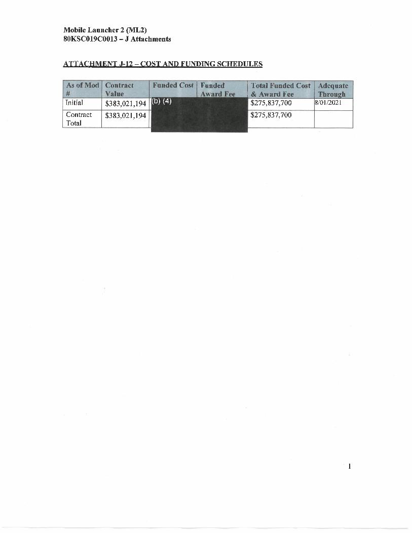

Mobile Launcher 2 (ML2) 80KSC019C0013 – J Attachments
1
ATTACHMENT J-13 – AWARD FEE EVALUATION PLAN (AFEP)
(a) PURPOSE The Award Fee Evaluation Plan (AFEP) defines the evaluation process by which the Government will encourage and reward the Contractor for timely, safe, high-quality, and cost-effective performance. The AFEP complies with FAR 16.401 and NFS 1816.405-2. The process enables the Government to focus on successful outcomes, overall technical, schedule, and cost performance, and to emphasize those aspects of critical milestone achievements essential to reach performance objectives. The process is a subjective assessment by the Government and may include consideration of predetermined objective performance criteria.
(b) END-ITEM AWARD FEE
Since the successful completion of this contract results in an end item deliverable, the true quality of Contractor performance cannot be measured until the end of the contract. Therefore, all award fee determinations prior to the end of the contract are interim and are superseded by the earned fee determination made in the final evaluation at contract completion, in accordance with clause NFS 1852.216-77, “Award Fee for End Item Contracts.” Interim award fee payments will be made based on each interim evaluation and are limited to the lesser of the interim evaluation score or 80 percent of the fee allocated to that period. The final rating will reflect the Government’s evaluation of the Contractor’s position at the end of the contract and success is measured against the end result.
(c) EVALUATION PROCESS
Performance evaluation and award fee will be determined semiannually in accordance with the KDP-KSC-P-2402, Award Fee Evaluation Process.
The Government will establish Areas of Emphasis (AOEs) to identify the performance elements of particular importance which are deserving of special attention during the evaluation period. AOEs will include specific milestone events and items of particular risk anticipated during the award fee evaluation period. Draft AOEs will be coordinated with the Contractor prior to finalizing the AOEs. The Contracting Officer (CO) will establish and formally communicate the final AOEs to the Contractor 15 calendar days prior to the start of a new evaluation period. Changes to AOEs may be made during the current evaluation period with mutual agreement between the Government and the Contractor.
While the goal is to achieve mutual understanding and agreement on the terms in this AFEP through positive communication and collaboration, the Government reserves the right to unilaterally revise the AFEP, if necessary. Final revisions to the plan will be communicated by the CO to the Contractor and will go into effect in the next evaluation period.
The Government technical representatives will assess the Contractor’s performance throughout the evaluation period. The Government will work closely with the Contractor to track performance, and the Contracting Officer Representative (COR) will clearly

Mobile Launcher 2 (ML2) 80KSC019C0013 – J Attachments
2
communicate any Contractor performance levels which require immediate remedial attention at any time during the evaluation period.
Within 30 calendar days following each evaluation period, the COR will prepare a summary report on the evaluation of the Contractor's performance based on the AOE, Government surveillance data, and contractor-furnished data. The Contractor shall be furnished a copy of the evaluation report for the period. Within five working days from receipt of the evaluation report, the Contractor may submit additional data relevant to the performance evaluation in writing to the COR. The Contractor also has the option of making a presentation to the Award Fee Board (AFB) and Fee Determination Official (FDO) on that period’s performance.
In accordance with KDP-KSC-P-2402, the AFB will review and consider the summary evaluation report prepared by the COR, and additional Contractor data, if any. The COR will be the focal point for the accumulation and development of performance evaluation reports, reviews, and presentations, as well as discussions with ML2 management on award fee matters.
(d) EVALUATION FACTORS AND WEIGHTED SCORING
The Government will use four factors – Technical & Management, Schedule, Cost Control, and Small Business Utilization - to determine the Total Award Fee Score for each evaluation period. The Government may apply AOEs and objective metrics to the evaluation factors, as necessary, to assist in the subjective evaluation of contract performance.
Evaluation Factors:
(1) Technical & Management:
The Government will evaluate major elements of the Contractor’s technical and management performance, such as efficiency and effectiveness of design aspects, technical integration, risk management, and construction operations; innovative solutions to design and construction, safety and quality performance; the Contractor’s ability to manage and integrate team members; and managerial and business performance. Of particular importance throughout the life of the project is the Contractor’s ability to communicate and collaborate with the Government, and maintain flexibility to respond to changes in requirements while minimizing the impact to cost and schedule. The Government will use these key aspects to develop a performance evaluation score (PES). AOEs and metrics will be used to assist the Government in the subjective evaluation of contract performance, but they will not encompass the entire spectrum of performance that will be evaluated in determining the performance score. The Government will evaluate the Contractor’s estimate at completion (EAC), variance analysis, and integration of subcontractors performance within the Contractor’s EVMS. Other pertinent factors included under the contract and general factors bearing upon overall Contractor performance will be considered in the evaluation as the facts and circumstances of each period may require.

Mobile Launcher 2 (ML2) 80KSC019C0013 – J Attachments
3
An overall fee rating of unsatisfactory will be assigned for any interim evaluation period in which there is a major breach of safety or security (see 1852.223-75, Major Breach of Safety which is incorporated in Section H.2). To ensure that the final award fee evaluation at contract completion reflects any major breach of safety or security, in an interim period, the overall award fee pool will be reduced by the amount of the fee available for the period in which the major breach occurred if an unsatisfactory fee rating was assigned because of a major breach of safety or security.
(2) Schedule:
The Government will evaluate the Contractor’s project schedule progress toward contract completion considering the totality of circumstances during the rating period. Quantitative measures such as EVM data or milestone completion will be considered but will not form the entirety of the schedule evaluation. The Government will utilize the Contractor’s project schedule and associated commitments as a metric. The Government will also assess the quality and effectiveness of the Contractor’s project schedule, including, but not limited to, the Contractor’s ability to: maintain schedule accuracy and usefulness; clearly demonstrate and understand the critical path activities; and proactively address and mitigate future schedule risks, changes, and conflicts. The Contractor’s ability to manage, preserve, and objectively demonstrate healthy schedule margins will also be evaluated by the Government.
(3) Cost Control:
The predominant consideration of this factor will be a measurement of the Contractor’s performance against the negotiated estimated cost of the contract for the evaluation period. The Government will utilize quantitative measures in assessing cost performance, but it will not form the entirety of the cost performance evaluation. The Contractor’s ability to properly plan, phase, project and present a cost plan will be crucial aspects. The Government will also evaluate the Contractor’s capability to accurately relate and explain cost variances to the cost plan and correlating other key influences like technical and schedule issues. The estimated cost will be adjusted to include the value of changes and may be adjusted to include the value for costs outside of the contractor’s control. Additionally, cost performance will be evaluated for efficiencies, cost reductions achieved through learning curves, process improvements and use of technology. Emphasis on cost control will be balanced against other performance requirement objectives. The Contractor must not pursue cost cutting methods to the point that overall performance is significantly degraded (reference NFS 1816.405-274 (e)).
(4) Small Business Utilization:
The Government will evaluate the Contractor’s success in fostering small business participation in the project, as defined in the Small Business Subcontracting Plan incorporated into the contract pursuant to FAR 52.219-9. The evaluation will include the extent to which subcontracting goals have been met or exceeded, the Contractor’s outreach efforts, timely and accurate progress reporting, and any other objectives

Mobile Launcher 2 (ML2) 80KSC019C0013 – J Attachments
4
included in the Subcontracting Plan. The evaluation of progress against subcontracting goals is subjective rather than objective, and will take into consideration the circumstances in which goals were pursued during the rating period.
Weighted Scoring:
The following adjective ratings, definitions, and numerical score ranges shall be used to define the various levels of performance under the contract, in accordance with FAR 16.401(3)(iv) and NFS 1816.405-275.
Adjectival
Rating Numerical
score Description
Excellent 91 - 100 Contractor has exceeded almost all of the significant award-fee criteria and has met overall cost, schedule, and technical performance requirements of the contract in the aggregate as defined and measured against the criteria in the award-fee plan for the award-fee evaluation period.
Very Good 76 - 90 Contractor has exceeded many of the significant award-fee criteria and has met overall cost, schedule, and technical performance requirements of the contract in the aggregate as defined and measured against the criteria in the award-fee plan for the award-fee evaluation period.
Good 51-75 Contractor has exceeded some of the significant award-fee criteria and has met overall cost, schedule, and technical performance requirements of the contract in the aggregate as defined and measured against the criteria in the award-fee plan for the award-fee evaluation period.
Satisfactory 50 Contractor has met overall cost, schedule, and technical performance requirements of the contract in the aggregate as defined and measured against the criteria in the award-fee plan for the award-fee evaluation period.
Unsatisfactory Less than 50
Contractor has failed to meet overall cost, schedule, and technical performance requirements of the contract in the aggregate as defined and measured against the criteria in the award-fee plan for the award-fee evaluation period.
The Government will score each evaluation factor 0-100 based on the performance evaluation and according to the ratings defined in the table above.
Each evaluation factor score will be weighted based on the following contributions:
Factor Weight Technical & Management: 40% Schedule: 25%

Mobile Launcher 2 (ML2) 80KSC019C0013 – J Attachments
5
Cost Control: 25% Small Business Utilization: 10%
Total: 100%
The Government will utilize the following formula to calculate the Total Award Fee Score. An example is provided below:
Total Award Fee Score = SUM [(Score for each Factor) x (Respective Weight%)]
The Total Award Fee Score, as calculated above, is subject to additional conditions described in NFS 1816.405-274.
(e) AWARD FEE PERFORMANCE DETERMINATION
The FDO will unilaterally determine a performance score and award fee after consulting with the COR and AFB. The FDO for ML2 will be the Program Manager of the KSC Exploration Ground Systems (EGS) Program. Generally, the FDO will make the award fee determination within 40 calendar days from the end of the period being evaluated. The FDO’s unilateral determination will not be subject to the clause of this contract entitled “Disputes” and there are no provisions for additional appeal rights. After receipt of the FDO’s Award Fee Determination Letter, the CO will promptly prepare a contract modification reflecting the award fee adjective rating, weighted evaluation score, and award fee amount.

Mobile Launcher 2 (ML2) 80KSC019C0013 – J Attachments
6
Award Fee Calculation Example The following example provides insight into the Award Fee calculation methodology:
Evaluation Factor Numerical
score Weighting
Technical & Management 90 40% Schedule 85 25% Cost Control 80 25% Small Business 95 10% Therefore, Total Award Fee Score = (90 x 0.40) + (85 x 0.25) + (80 x 0.25) + (95 x 0.10) = 86.75 = 87 Decimal >.49 score rounds up

ML2 Design-Build Areas of Emphasis First Award Fee Period
(a) Within 14 days after award, the Contractor shall:(1) Develop a Site Specific Safety and Health Plan (SSHP) in accordance with
Attachment J-4, DRD 1.0-2.(a) Develop in accordance with KNPR 8715.7, KSC Construction ContractorSafety and Health Practices Procedural Requirements.(b) Collaboration with the Government in development of the SSHP.
(b) Within 30 days after award, the Contractor shall:(1) Develop an integrated project schedule in accordance with Attachment J-4, DRD 1.0-
6 and provide evidence that the necessary processes/tools are in place to ensureaccurate data input for EVM.
(a) Fully coordinated and integrated within the contractor team.(b) Partner the results with the Government.
(2) Develop an Earned Value Management System (EVMS) Implementation Plan inaccordance with Attachment J-4, DRD 1.0-9.
(a) Contractor shall develop and submit an EVMS implementation plan to thegovernment for approval, if the Contractor proposes to use an EVMS that has notbeen determined by NASA or DCMA to be in compliance with the guidelines inthe Electronic Industries Alliance Standard 748, Earned Value ManagementSystems (EIA-748).(b) Partner development of the Earned Value Management System (EVMS)Implementation Plan with the Government.
(3) Establish a document management and collaboration tool and provide Governmentaccess and training (SOW 1.2 (a)).
(a) Develop collaboration tool structure and standard stakeholder distributions.(b) Document decisions, agreements, guidance and assigned actions in meetingminutes or memorandum of records from meetings with Government personnel.(c) Demonstrate accessibility of required stakeholders to information.
(4) Develop an initial Quality Assurance (QA) Plan in accordance with Attachment J-1,Section 4.1.c.
(a) Develop in accordance with AS 9100 and collaborate with the Governmentprior to initial submittal.(b) Ensure compliance with the quality requirements of the Specifications for bothon-site and off-site work.(c) Partner development of the Quality Assurance (QA) Plan with theGovernment.
(c) Within 60 days after award, the Contractor shall:(1) Develop a Configuration Management Plan in accordance with Attachment J-4, DRD
1.0-3.(a) Develop in accordance with ANSI/EIA 649.(b) Identify ML2 Configuration Control Board (CCB) members and defineGovernment stakeholder involvement.

(c) Partner the development of the Configuration Management Plan with the Government.
(d) Within 3 months after award, the Contractor shall place emphasis on the design charrette activities, which will be critical to establishing specific technical/design expectations and gaining early project momentum.
(1) Ensure all key subject matter experts (SME) are participating in the process. (2) Establish connections between contractor and Government SMEs. (3) Substantial completion of design charrettes (SOW Section 3.1).
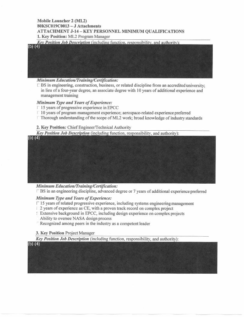


Mobile Launcher 2 (ML2) 80KSC019C0013 – J Attachments ATTACHMENT J-14 – KEY PERSONNEL MINIMUM QUALIFICATIONS
Minimum Type and Years of Experience: 15 years of EPC experience, including 5 years in commissioning and testing 5 years of supervision/management experience Ability to serve as single POC for validation and commissioning activities for complex systems

Mobile Launcher 2 (ML2) 80KSC019C0013 – J Attachments
ATTACHMENT J-15 – CONSTRUCTION WAGE RATE REQUIREMENTS
1

General Decision Number: FL180001 10/05/2018 FL1
Superseded General Decision Number: FL20170001
State: Florida
Construction Types: Building, Heavy and Highway
County: Brevard County in Florida.
**CAPE CANAVERAL AIR STATION, PATRICK AIR FORCE BASE KENNEDY SPACE CENTER AND MALABAR RADAR SITE IN BREVARD COUNTY BUILDING CONSTRUCTION PROJECTS (does not include residential construction consisting of single family homes and partments up to and including 4 stories) HEAVY AND HIGHWAY CONSTRUCTION PROJECTS
Note: Under Executive Order (EO) 13658, an hourly minimum wage of $10.35 for calendar year 2018 applies to all contracts subject to the Davis-Bacon Act for which the contract is awarded (and any solicitation was issued) on or after January 1, 2015. If this contract is covered by the EO, the contractor must pay all workers in any classification listed on this wage determination at least $10.35 per hour (or the applicable wage rate listed on this wage determination, if it is higher) for all hours spent performing on the contract in calendar year 2018. The EO minimum wage rate will be adjusted annually. Please note that this EO applies to the above-mentioned types of contracts entered into by the federal government that are subject to the Davis-Bacon Act itself, but it does not apply to contracts subject only to the Davis-Bacon Related Acts, including those set forth at 29 CFR 5.1(a)(2)-(60). Additional information on contractor requirements and worker protections under the EO is available at www.dol.gov/whd/govcontracts.
Modification Number Publication Date 0 01/05/2018 1 01/12/2018 2 03/16/2018 3 04/20/2018 4 06/01/2018 5 07/06/2018 6 08/17/2018 7 09/21/2018 8 10/05/2018
ASBE0067-001 01/01/2018
Rates Fringes
Asbestos Workers/Insulator (Includes the application of all insulating materials, protective coverings, coatings and finishings to all types of mechanical systems).........................$ 27.89 15.19
222

---------------------------------------------------------------- ASBE0067-002 07/01/2017
Rates Fringes
HAZARDOUS MATERIAL HANDLER (Includes preparation, wetting, stripping, removal, scrapping, vacuuming,bagging, and disposing of all insulation materials from mechanical systems, whether they contain asbestos or not).........$ 16.50 10.90 ---------------------------------------------------------------- BOIL0433-001 03/01/2018
Rates Fringes
BOILERMAKER......................$ 30.07 22.71 ---------------------------------------------------------------- BRFL0008-001 01/01/2018
Rates Fringes
BRICKLAYER (BRICKLAYERS, BLOCKLAYERS, PLASTERERS, TERRAZZO WORKERS, TILE SETTERS AND CEMENT MASONS) COMMERCIAL..................$ 22.68 6.31 INDUSTRIAL..................$ 26.08 6.31
INDUSTRIAL work includes: Bulk plants, power houses, chemical plants, missile sites including all work at Cape Canaveral Air Force Station and Kennedy Space Flight Center.
---------------------------------------------------------------- CARP1000-001 07/01/2014
Rates Fringes
MILLWRIGHT.......................$ 29.48 12.40 ---------------------------------------------------------------- * CARP1905-002 06/01/2017
Rates Fringes
Carpenters: *INDUSTRIAL:CARPENTERS.................$ 25.25 7.55 PILEDRIVERMEN..............$ 21.75 8.65
COMMERCIAL: CARPENTERS.................$ 23.11 9.85 PILEDRIVERMEN..............$ 21.75 8.65
---------------------------------------------------------------- ELEC0222-001 09/01/2016
Rates Fringes
223

Line Construction: CABLE SPLICER...............$ 35.72 5.00+24.5% GROUNDMAN...................$ 19.39 5.00+24.5% LINEMAN; HEAVY EQUIPMENT OPERATOR....................$ 34.02 5.00+24.5% ---------------------------------------------------------------- ELEC0756-001 09/03/2018
Rates Fringes
ELECTRICIAN Cable Splicer...............$ 28.09 3%+12.23 Wireman.....................$ 28.09 3%+12.23 ---------------------------------------------------------------- ELEV0139-001 01/01/2018
Rates Fringes
ELEVATOR MECHANIC................$ 41.40 32.645
FOOTNOTE: A. Employer contributions 8% of regular hourly rate to vacation pay credit for employee who has worked in business more than 5 years; Employer contributions 6% of regular hourly rate to vacation pay credit for employee who has worked in business less than 5 years.
Paid Holidays: New Year's Day; Memorial Day; Independence Day; Labor Day; Thanksgiving Day; The Friday after Thanksgiving Day; and Christmas Day.
---------------------------------------------------------------- ENGI0673-001 05/01/2013
Rates Fringes
Power equipment operators: GROUP 1.....................$ 26.30 10.85 GROUP 2.....................$ 24.14 10.85 GROUP 3.....................$ 23.00 10.85 GROUP 4.....................$ 20.36 10.85
POWER EQUIPMENT OPERATORS
CLASSIFICATIONS GROUP 1: Tower Crane, Locomotive Crane, Crawler Crane, Truck Crane, Hydro Crane, Piledriver (incluidng auger and boring machine)
GROUP 2: Mechanic/Welder and operators of: Gantry Crane, Bridge Crane, Clam Shell, Dragline, Backhoe, Gradeall, Grader, Sideboom Cat, Hulti-Drum Hoist, Highlift (10' or higher), Locomotive Engineer, Tugboat Captain (150 hp or more), Concrete Pump with boom
GROUP 3: Bulddozers, Forklifts, Straddle Buggy, Single Drum Hoist, Winch Truck, Trenching Machine, Concrete Paver, Scraper, Loader, Asphalt Paving Machine, Lubricating Engineer, Fireman, Concrete Breaking Machine, Concrete Mixer
224

GROUP 4: Tractors, Wellpoint System Operator and Installer, Air Compressor, Pulver Mixer, Motor boat, Power Boat, Power Sweeper, Welding Machine, Oiler, Mechanic's Helper, Pump, Conveyor, Roller, Watertruck, Asphalt distributor, Concrete Pump (trailer type), Utility Operator
---------------------------------------------------------------- * IRON0808-001 01/01/2018
Rates Fringes
IRONWORKER.......................$ 26.03 13.95 ---------------------------------------------------------------- LABO0517-001 05/01/2017
Rates Fringes
Laborers: Asbestos Abatement, Hazardous and Toxic Waste Removal Laborers; (On all mechaincal systems: Lead Base Paint Removal;pipes, boilers, ducts, flues, breechings, ect.; that are going to be scrapped, the removal of all insulating materials whether they contain asbestos or not shall be the exclusive work of the laborers;.......$ 19.45 7.85 Carpenter Tender, Cement Mason Tender, Block/ Bricklayer Tender Plasterer Tender............$ 19.20 7.85 Demolition Laborers.........$ 19.20 7.85 General Laborer.............$ 19.20 7.85 Pipelayer Laborer, Laborer engaged in the pouring of concrete, mortar mixers, masonry forklift operator, and operation of power tools.......................$ 19.20 7.85 ---------------------------------------------------------------- PAIN0078-001 08/01/2018
Rates Fringes
GLAZIER..........................$ 24.71 12.95 ---------------------------------------------------------------- PAIN0078-002 08/01/2018
Rates Fringes
PAINTER..........................$ 24.71 12.95 ---------------------------------------------------------------- PLUM0295-001 01/01/2018
Rates Fringes
225

Plumber/Pipefitter/Steamfitter INDUSTRIAL: Bulk Plants, Power-houses, Chemical Plants, Missile Sites, (Including all Work at Cape Canaveral Air Force Station and Kennedy Space Flight Center but excluding work performed at Patrick Air Force Base and Malabar Radar Site), Oil Refineries, etc., and such other work which is related to and considered a part of the above type projects....................$ 34.11 18.78 Schools, Hospitals, Shopping Centers, and work not listed as Industrial....$ 34.11 18.78 ---------------------------------------------------------------- ROOF0136-001 08/01/2016
Rates Fringes
ROOFER...........................$ 19.99 8.16 ---------------------------------------------------------------- SFFL0821-002 07/01/2018
Rates Fringes
SPRINKLER FITTER Commercial..................$ 28.38 18.89 Industrial..................$ 30.73 18.89
Industrial: Jobs covering sugar mills, power plants, trash burning plants, military installations and Cape Kennedy. All other work shall be commercial rate.
---------------------------------------------------------------- SHEE0015-001 12/01/2013
Rates Fringes
SHEET METAL WORKER...............$ 24.12 13.95 ----------------------------------------------------------------
WELDERS - Receive rate prescribed for craft performing operation to which welding is incidental.
================================================================
Note: Executive Order (EO) 13706, Establishing Paid Sick Leave for Federal Contractors applies to all contracts subject to the Davis-Bacon Act for which the contract is awarded (and any solicitation was issued) on or after January 1, 2017. If this contract is covered by the EO, the contractor must provide employees with 1 hour of paid sick leave for every 30 hours
226

they work, up to 56 hours of paid sick leave each year. Employees must be permitted to use paid sick leave for their own illness, injury or other health-related needs, including preventive care; to assist a family member (or person who is like family to the employee) who is ill, injured, or has other health-related needs, including preventive care; or for reasons resulting from, or to assist a family member (or person who is like family to the employee) who is a victim of, domestic violence, sexual assault, or stalking. Additional information on contractor requirements and worker protections under the EO is available at www.dol.gov/whd/govcontracts.
Unlisted classifications needed for work not included within the scope of the classifications listed may be added after award only as provided in the labor standards contract clauses (29CFR 5.5 (a) (1) (ii)).
----------------------------------------------------------------
The body of each wage determination lists the classification and wage rates that have been found to be prevailing for the cited type(s) of construction in the area covered by the wage determination. The classifications are listed in alphabetical order of "identifiers" that indicate whether the particular rate is a union rate (current union negotiated rate for local), a survey rate (weighted average rate) or a union average rate (weighted union average rate).
Union Rate Identifiers
A four letter classification abbreviation identifier enclosed in dotted lines beginning with characters other than "SU" or "UAVG" denotes that the union classification and rate were prevailing for that classification in the survey. Example: PLUM0198-005 07/01/2014. PLUM is an abbreviation identifier of the union which prevailed in the survey for this classification, which in this example would be Plumbers. 0198 indicates the local union number or district council number where applicable, i.e., Plumbers Local 0198. The next number, 005 in the example, is an internal number used in processing the wage determination. 07/01/2014 is the effective date of the most current negotiated rate, which in this example is July 1, 2014.
Union prevailing wage rates are updated to reflect all rate changes in the collective bargaining agreement (CBA) governing this classification and rate.
Survey Rate Identifiers
Classifications listed under the "SU" identifier indicate that no one rate prevailed for this classification in the survey and the published rate is derived by computing a weighted average rate based on all the rates reported in the survey for that classification. As this weighted average rate includes all rates reported in the survey, it may include both union and non-union rates. Example: SULA2012-007 5/13/2014. SU indicates
227

the rates are survey rates based on a weighted average calculation of rates and are not majority rates. LA indicates the State of Louisiana. 2012 is the year of survey on which these classifications and rates are based. The next number, 007 in the example, is an internal number used in producing the wage determination. 5/13/2014 indicates the survey completion date for the classifications and rates under that identifier.
Survey wage rates are not updated and remain in effect until a new survey is conducted.
Union Average Rate Identifiers
Classification(s) listed under the UAVG identifier indicate that no single majority rate prevailed for those classifications; however, 100% of the data reported for the classifications was union data. EXAMPLE: UAVG-OH-0010 08/29/2014. UAVG indicates that the rate is a weighted union average rate. OH indicates the state. The next number, 0010 in the example, is an internal number used in producing the wage determination. 08/29/2014 indicates the survey completion date for the classifications and rates under that identifier.
A UAVG rate will be updated once a year, usually in January of each year, to reflect a weighted average of the current negotiated/CBA rate of the union locals from which the rate is based.
----------------------------------------------------------------
WAGE DETERMINATION APPEALS PROCESS
1.) Has there been an initial decision in the matter? This can be:
* an existing published wage determination * a survey underlying a wage determination * a Wage and Hour Division letter setting forth a position on a wage determination matter * a conformance (additional classification and rate) ruling
On survey related matters, initial contact, including requests for summaries of surveys, should be with the Wage and Hour Regional Office for the area in which the survey was conducted because those Regional Offices have responsibility for the Davis-Bacon survey program. If the response from this initial contact is not satisfactory, then the process described in 2.) and 3.) should be followed.
With regard to any other matter not yet ripe for the formal process described here, initial contact should be with the Branch of Construction Wage Determinations. Write to:
Branch of Construction Wage Determinations Wage and Hour Division U.S. Department of Labor 200 Constitution Avenue, N.W.
228

Washington, DC 20210
2.) If the answer to the question in 1.) is yes, then an interested party (those affected by the action) can request review and reconsideration from the Wage and Hour Administrator (See 29 CFR Part 1.8 and 29 CFR Part 7). Write to:
Wage and Hour Administrator U.S. Department of Labor 200 Constitution Avenue, N.W. Washington, DC 20210
The request should be accompanied by a full statement of the interested party's position and by any information (wage payment data, project description, area practice material, etc.) that the requestor considers relevant to the issue.
3.) If the decision of the Administrator is not favorable, an interested party may appeal directly to the Administrative Review Board (formerly the Wage Appeals Board). Write to:
Administrative Review Board U.S. Department of Labor 200 Constitution Avenue, N.W. Washington, DC 20210
4.) All decisions by the Administrative Review Board are final.
================================================================
END OF GENERAL DECISION
229

80KSC019C0013 - ML2
Page 1 of 1
DATA REQUIREMENT CONTRACT APPLICATION INFORMATION FOR DRL ML2
A. Item No.1.0-1
B. Line Item Title:
Monthly Project Management Status Review
C. Opr.
LX-D
D. Type
3
E. Inspect/Accept
6
F. Freq.
MO
G. Initial Sub.
Contract Effective Date+30 days
H. As Of Date
30/10
J. Remarks:
Type “D”: Electronic submittal followed by a presentation. Product shall be compatible with Microsoft Office suite of software.
K. Distribution
LX-DLX-B1GG-C-E
Totals No. Type
3 D
DATA REQUIREMENT DESCRIPTION 1. Title
Review, Monthly Project Management Status Review
2.Number
1.0-1
3. Use
To provide an overview of the status of the ML2 contract activities to NASA Exploration Ground Systems (EGS) Program Management and other stakeholders.
4. Date
5. Organization
7. Interrelationship 6. References
8. Preparation Information
The Contractor shall present a documented Project Management Status Review to NASA EGS Program Management and otherstakeholders each month. The presentation shall provide an overview of ML2 contract performance including any significant initiatives, issues, and concerns. The contractor shall include cost information in discussions of schedule status, technical performance, and risk using earned value management as an integrating tool. Contractor subject matter experts shall be present at the review to answer questions on topics presented.
The presentation shall address:
1. All areas of the contract with emphasis on project health with regards to meeting cost and schedule objectives.2. Significant cost/schedule technical variances and trends.3. Projected cost and schedule impacts as well as corrective action plans.4. Major accomplishments since last PMR.5. Safety close calls or violations.6. Process improvements and innovations.7. Technical challenges and project risks.8. Any other items of current interest.
KSC FORM 16-246 NS (REV. 02/04) PREVIOUS EDITIONS MAY BE USED
Attachment J-4

80KSC019C0013 - ML2
DATA REQUIREMENT CONTRACT APPLICATION INFORMATION FOR DRL ML2
A. Item No.1.0-2
B. Line Item Title:
Site Specific Safety and Health Plan
C. Opr.
LX-D
D. Type
1
E. Inspect/Accept
3
F. Freq.
AR
G. Initial Sub.
Contract Effective Date + 14 days
H. As Of Date
AR
J. Remarks:
Type “D”: Electronic submittal. Product shall be compatible with Microsoft Office suite of software.
K. Distribution
LX-D
Totals
No. Type
1 D
DATA REQUIREMENT DESCRIPTION 1. Title
Plan, Site Specific Safety and Health
2.Number
1.0-2
3. Use
To document the Contractor’s plan for addressing construction safety and health for the ML2 contract.
4. Date
5. Organization
7. Interrelationship 6. References
8. Preparation Information
Site Specific Safety and Health Plan will be in accordance with KNPR 8715.7, KSC Construction Contractor Safety and HealthPractices Procedural Requirements.
KSC FORM 16-246 NS (REV. 02/04) PREVIOUS EDITIONS MAY BE USED
Attachment J-4

80KSC019C0013 - ML2
Page 1 of 1
DATA REQUIREMENT CONTRACT APPLICATION INFORMATION FOR DRL ML2
A. Item No.1.0-3
B. Line Item Title:
Configuration Management Plan
C. Opr.
LX-D
D. Type
1
E. Inspect/Accept
3
F. Freq.
AR
G. Initial Sub.
Contract Effective Date + 60 days
H. As Of Date
AR
J. Remarks:
Type “D”: Electronic submittal. Product shall be compatible with Microsoft Office suite of software.
K. Distribution
LX-D
Totals No. Type
1 D
DATA REQUIREMENT DESCRIPTION 1. Title
Plan, Configuration Management
2.Number
1.0-3
3. Use
To document the process, procedures, and authority for the ML2 Configuration Management.
4. Date
5. Organization
7. Interrelationship 6. References
8. Preparation Information
The Contractor shall develop and maintain a configuration management plan for the ML2. The plan shall comply with ANSI/EIA 649 and address the Contractor’s plan for review, disposition, and approval authority of proposed Contractor-implemented modifications, proposed Government requirements changes, or work by others resulting in changes to Contractor’s configured documentation (e.g. drawings, specifications, models) including related software and any other configuration related issues.
The Plan shall also address the Contractor’s proposed ML2 Configuration Control Board (CCB) and the proposed members in the CCB. The Plan shall address the process and format for submission of documentation to the ML2 CCB, verification of change, and documentation closure.
The initial CM plan and role and responsibilities shall be partnered with the Government prior to formalizing the document.
KSC FORM 16-246 NS (REV. 02/04) PREVIOUS EDITIONS MAY BE USED
Attachment J-4

80KSC019C0013 - ML2 Attachment J-4
Page 1 of 12
DATA REQUIREMENT CONTRACT APPLICATION INFORMATION FOR DRL ML2
A. Item No.1.0-4
B. Line Item Title:
Financial Management Reports (e533)
C. Opr.
GG-C-E
D. Type
3
E. Inspect/Accept
6
F. Freq.
MO
G. Initial Sub.
See Block J
H. As Of Date
See block J
J. Remarks:
The e533 Flat File is due monthly within 10 working days after the close of the contractor’s accounting period. The contractor shall submit type “D”, electronic copies that are compatible with Microsoft Office software.
K. Distribution
OPR/Mail Code: GG-C-E KSC CFO/Mail Code: GG-AB CO/Mail Code: OP-ES COR/Mail Code: LX-D PP&C/Mail Code: LX-B1
Totals No. Type
5 D
DATA REQUIREMENT DESCRIPTION 1. Title
Flat File, e533
2.Number
3. Use
To provide monthly and cumulative accumulated expenditures and projections of contract costs.
4. Date
5. Organization
KSC7. Interrelationship
WBS, 533, IPMR
6. References
NPR 9501.2
8. Preparation Information
The contractor will provide the e533 Flat File that contains detail information for each Reporting Category (RC). A RC correlates to a task order, delivery order, or Work Breakdown Structure (WBS), and is the level at which cost is reported. Each RC can have Sub-Reporting Category line items (detailed cost elements) that add up to a RC. The contractor shall coordinate with the NASA Resource Analyst assigned to the contract in order to establish and maintain the RC that the contractor shall use to comply with this data requirement. The chart below describes the data elements that shall be included in this section of the flat file (see attached Exhibit A, Agency Defined File Format for specific layout details).
The e533Flat File (see Exhibit A below) must be saved as a text file with no extension (do not include .txt after the file name) and named in strict accordance with the specific format described in the attached Agency Defined File Format document.
KSC FORM 16-246 NS (REV. 02/04) PREVIOUS EDITIONS MAY BE USED

80KSC019C0013 - ML2 Attachment J-4
Page 2 of 12
DATA REQUIREMENT (Continuation Sheet) 8. Preparation Information
Data Element Name Description Reporting Category (RC) Task, Delivery Order, Work Breakdown Structure Cost Incurred for Month (7a) Prior month actual cost incurred for each RC (column 7a
on NF533M) HR/WYE Incurred for Month (7a) Prior month actual HR/WYE incurred for each RC
(column 7a on NF533M) Contract prior month planned cost (7b) Planned cost for prior month for each RC (column 7b on
NF533M) Contract ITD cost (7c) Contract inception-to-date (ITD) cost for each RC
(column 7c on NF533M) Contract planned ITD cost (7d) Contract planned ITD cost for each RC (column 7d on
NF533M) Current month estimated cost (8a) Cost estimate for the current month for each RC (column
8a on NF533M) Current month estimated HR/WYE (8a)
HR/WYE estimate for the current month for each RC (column 8a on NF533M)
Next month estimated cost (8b) Estimated cost for next month for each RC (column 8b on NF533M)
Balance of Contract Balance of contract for the remaining estimate to complete for each RC (column 8c on NF533M)
Contractor Estimate Contractor estimate for the total estimate to complete entire scope of contract for each RC (column 9a on NF533M)
Contract Value Contract value based upon contract modifications for each RC (column 9c on NF533M)
Unfilled orders outstanding Unfilled orders outstanding at the end of the reporting period for each RC (column 10 on NF533M)
Reporting Category level Used by NASA’s accounting system to determine the RC level
Reporting Category Identifier Identifies if the RC is an actual Reporting Category or a Sub-Reporting
KSC FORM 16-246 NS (REV. 02/04) PREVIOUS EDITIONS MAY BE USED

February 8, 2018
Electronic 533 File Format
Page 3 of 12
In order to automate the submittal of the electronic 533 report, contractors must provide a file in the format below. File names must be provided in a specific format. Each file name will begin with the SAP 2 Character center abbreviation listed below. The contract number and date will be included in the file name as well. Below is a sample file name. KE80KSC017C0012_2018_01_30
SAP 2 Charter Center Abbreviations Headquarters HQ Dryden DR Marshall MA Goddard GO Ames AM Stennis ST Glenn GL Johnson JO Langley LA Kennedy KE
Comments The data source for this integration is a 533 electronic submittal data file. It will contain a header record for Contract totals; detail records for Reporting Category totals; and a trailer record for file total record counts. If multiple Contracts are to be sent, then a separate file for each contract will need to be submitted.
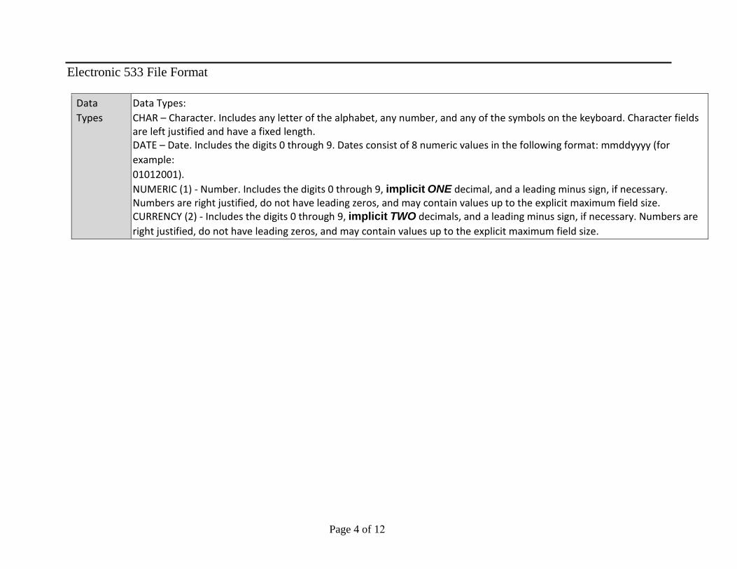
Electronic 533 File Format
Page 4 of 12
Data Types
Data Types: CHAR – Character. Includes any letter of the alphabet, any number, and any of the symbols on the keyboard. Character fields are left justified and have a fixed length. DATE – Date. Includes the digits 0 through 9. Dates consist of 8 numeric values in the following format: mmddyyyy (for example: 01012001). NUMERIC (1) - Number. Includes the digits 0 through 9, implicit ONE decimal, and a leading minus sign, if necessary. Numbers are right justified, do not have leading zeros, and may contain values up to the explicit maximum field size. CURRENCY (2) - Includes the digits 0 through 9, implicit TWO decimals, and a leading minus sign, if necessary. Numbers are right justified, do not have leading zeros, and may contain values up to the explicit maximum field size.

Electronic 533 File Format
Page 5 of 12
Agency Defined File Format Header (Non-Repeating Segment)
CCR Extension
Data Element
Description Contractor Initial Data Mapping
533 Require
d/ Optional
Field Name St Pos
EndP os
Le n
Formt
HEADER:
Record Type Used to determine the record type
‘HD’ for Header Required RECORD_TYPE 1 2 2 CHAR
Contract Number
Contract Number Header field— submitted with CONTRACTOR data or defaulted by interface or extension
Required CONTRACT_NUMBER 3 42 40 CHAR (Left Justified)
Latest definitive Modification Number
MOD_NUMBER 43 48 6 CHAR
Accrual Date
Date the data was generated for.
Accrual Date. MM01YYYY, where MM is the Accrual Month and YYYY is the fiscal year
Required ACCRUAL_DATE 49 56 8 DATE MM01YYYY
Report Period End Date
Report Period End Date
Header field— submitted with CONTRACTOR data or defaulted by interface or extension
Required REP_END_DATE 57 64 8 DATE

Electronic 533 File Format
Page 6 of 12
CCR Extension
Data Element
Description Contractor Initial Data Mapping
533 Require
d/ Optional
Field Name St Pos
EndP os
Le n
Formt
Operating Days
Operating days Header field— submitted with CONTRACTOR data
Required OPER_DAYS 65 70 6 NUMERIC
Date Received
Date Received System Date upon which the cost data is loaded into the CCR Extension
Required DATE_REC 71 78 8 DATE
CCR Format ‘M’ for Monthly and ‘Q’ for Quarterly
Submitted with CONTRACTOR data
Required CCR_FORMAT 79 79 1 CHAR
Cost Unit of Measure
Cost Unit of Measure
Submitted with CONTRACTOR data
Required COST_UOM 80 81 2 CHAR
HR/WYE Unit of Measure
Hour/Work-YearEquivalent Unit of Measure
Submitted with CONTRACTOR data
Required HR_WYE_UOM 82 83 2 CHAR
Authorized Contractor Representative – Name of Contractor Approving Officer
AUTH_SIGNATURE 84 108 25 CHAR

Electronic 533 File Format
Page 7 of 12
Authorized Contractor Representative Date Signed – Date CCR is approved/signed by authorized contractor representative
AUTH_SIGNATURE_DATE 109 116 8 DATE MMDDYYYY
Grand Total Cost Incurred Month (7a)
The Grand Total Contract Prior Month Actual Dollars Column 7a reports actual costs for the prior
Submitted with CONTRACTOR data
Required .
GT_COST_INCUR_MONTH 117 129 13 CURRENCY(2)
CCR Extension
Data Element
Description Contractor Initial Data Mapping
533 Require
d/ Optional
Field Name St Pos
EndP os
Le n
Formt
month.
Grand Total HR/WYE (7a)
The Grand Total Contract Prior Month Actual Hours Column 7a reports actual HR or WYE for the prior month.
Submitted with CONTRACTOR data
Required if detailed line item data is submitte d in monthly batch file.
GT_HRWYE_PRIOR_MONTH 130 139 10 NUMERIC(1)
The Grand Total Contract Prior Month Planned Dollars Column (7b) reports planned costs for the prior month.
GT_COST_PLANNED_MONTH 140 152 13 CURRENCY (2)

Electronic 533 File Format
Page 8 of 12
Grand Total Cost Incurred ITD (7c)
The Grand Total Contract Cost Dollars Column 7c which represents Contract Cost Inception to Date
Submitted with CONTRACTOR data
Required . Does not require detailed line item data if provided from Cost Incurred Month (7a)
GT_ITD_COST 153 165 13 CURRENCY (2)
Grand Total Cotract Planned Cost Dollars Column (7d) which represents Planned Contract Cost Inception to Date
GT_COST_PLANNED_ITD 166 178 13 CURRENCY (2)
Grand Total Estimated Cost (8a)
The Grand Total Contract Estimated Cost for first upcoming
Submitted with CONTRACTOR data
Required GT_EST_COST 179 191 13 CURRENCY (2)
CCR Extension
Data Element
Description Contractor Initial Data Mapping
533 Require
d/ Optional
Field Name St Pos
EndP os
Le n
Formt
month, or Current Month Estimate for cost.
Grand Total HR/WYE (8a)
The Grand Total Contract Estimated Hours for first upcoming month, or Current Month Estimate for
Submitted with CONTRACTOR data
Required if detailed line item data is provided for this column
GT_HRWYE_FIRST_MONTH 192 201 10 NUMERIC (1)

Electronic 533 File Format
Page 9 of 12
HR/WYE.
Grand Total Next Month Estimated Cost (8b)
The Grand Total Contract Estimated Cost for second upcoming month or Next Month Estimate for cost.
Submitted with CONTRACTOR data
Required if detailed line item data is provided for this column
GT_NEXT_MONTH_EST 202 214 13 CURRENCY (2)
Grand Total Balance of Contract for the remaining estimate to complete
GT_BALANCE_CONTRACT 215 227 13 CURRENCY (2)
Grand Total Contractor Estimate for the total estimate to complete entire scope of contract
GT_BALANCE_CONTRACTOR_ESTIMAT E 228 240 13 CURRENCY (2)
Grand Total Contract Value based upon Contract Modifications
GT_CONTRACT_VALUE 241 253 13 CURRENCY (2)
Grand Total Unfilled Orders Outstanding at end of reporting period
ST_UNFILLED ORDERS 254 266 13 CURRENCY (2)
Detail (Repeating Segment )

Electronic 533 File Format
Page 10 of 12
CCR Extension
Data Element
Description Contractor Initial Data Mapping
533 Required/ Optional
Field Name St Pos
End Pos
Len Format
CCR DETAIL LINE ITEMS:
Record Type ‘DM’ for Monthly column 7a Detail; ‘DQ’ for ITD Column 7c Detail
“RD” for Detail Required RECORD_TYPE 1 2 2 CHAR
Reporting Category
Reporting Category Line item field— submitted with CONTRACTOR data
Required SERV_ORD_CAT 3 26 24 CHAR
Cost Incurred Month (7a)
Prior Month incurred costs (ACTUALS) for given category.
Line item field— submitted with CONTRACTOR data
Required if detailed line item data is not provided from Cost Incurred Month (7c)
COST_INCUR_MONTH 27 39 13 CURRENCY (2)
HR/WYE Incurred Month (7a)
Prior month incurred hours worked [Actuals] for given category.
Line item field— submitted with CONTRACTOR data
Optional unless Required by contract for WYE calculation
HRWYE_INCUR_MONTH 40 49 10 NUMERIC (1)
Contract Prior Month Planned Dollars Column (7b) reports planned costs for the prior month
COST_PLANNED_MONTH 50 62 13 CURRENCY (2)
Contract Cost Dollars Column (7c) which represents Contract Cost Inception to Date
CUR_COST_INCUR_ITD 63 75 13 CURRENCY (2)
Contract Planned Cost Dollars Column (7d) which represents Planned Contract Cost Inception to Date
COST_PLANNED_ITD 76 88 13 CURRENCY (2)
Current Month Estimated
Estimated costs for first upcoming month for given category.
Line item field— submitted with CONTRACTOR data
Required. CUR_MONTH_EC 89 101 13 CURRENCY (2)

Electronic 533 File Format
Page 11 of 12
Cost (8a)
HR/WYE Current Month
Estimated hours for first upcoming month for given category. Will only be needed if labor hours are required to be
Line item field— submitted with CONTRACTOR
Optional unless Required by contract for WYE
HRWYE_CUR_MONTH_EST 102 111 10 NUMERIC (1)
CCR Extension
Data Element
Description Contractor Initial Data Mapping
533 Required/ Optional
Field Name St Pos
End Pos
Len Format
Estimate (8a) submitted electronically per contract. data calculation
Next Month Estimated Cost (8b)
Estimated costs for second upcoming month for given category.
Line item field— submitted with CONTRACTOR data
Required unless not part of Contract scope
NEXT_MONTH_EC 112 124 13 CURRENCY (2)
Balance of Contract for the remaining estimate to complete (8c)
BALANCE_CONTRACT 125 137 13 CURRENCY (2)
Contractor Estimate for the total estimate to complete entire scope of contract (9a)
CONTRACTOR_ESTIMATE 138 150 13 CURRENCY (2)
Contract Value based upon Contract Modifications
CONTRACT_VALUE 151 163 13 CURRENCY (2)
Unfilled Orders Outstanding at end of reporting period
UNFILLED ORDERS 164 176 13 CURRENCY (2)
Used by SAP to determine Reporting Category Level (1.1.2.2.1)
REPORTING_LEVEL 177 206 30 CHAR
Fill in an “X” if record is a Reporting Category. Otherwise, leave blank for Sub-Reporting Category Line Items and Element of Cost detail records. This field is used by SAP to determine if the record is a Reporting Category.
REPORTING_CAT_INDICATOR 207 207 1 CHAR

Electronic 533 File Format
Page 12 of 12
Trailer (provides the number of header & detail records sent from the contractor/vendor/center in order to verify the receipt of complete data after transmissi
CCR Extension Data Element
Description Contractor Initial Data Mapping
533 Required/ Optional
Field Name Start Pos
End Pos
Length Format
TRAILER:
Record Type Used by eGate to determine record type
“TL” for Trailer Required RECORD_TYPE 1 2 2 CHAR
Record Count Count of the number of Detail records sent to process (Detail Only)
Trailer field submitted with CONTRACTOR data
Required RECORD_COUNT 3 9 7 NUMERIC
CCR Extension Data Element
Description Contractor Initial Data Mapping
533 Required/ Optional
Field Name Start Pos
End Pos
Length Format
Value of spaces FILLER 10 207 198 CHAR

80KSC019C0013 - ML2
Page 1 of 7
DATA REQUIREMENT CONTRACT APPLICATION INFORMATION FOR DRL ML2
A. Item No.1.0-5
B. Line Item Title:
Financial Management Reports (533)
C. Opr.
GG-C-E
D. Type
3
E. Inspect/Accept
6
F. Freq.
MO
G. Initial Sub.
See Block J
H. As Of Date
See Block J
J. Remarks:
The NASA Form 533M report is due monthly within 10 working days after the close of the contractor’s accounting period. The NASA Form 533Q is waived except for submission of an initial NASA Form 533Q baseline report that is due 30 days after contract start date identifying contract negotiated contract value by element of cost. The contractor shall submit type “D”, electronic copies that are compatible with Microsoft Office software.
K. Distribution
OPR/Mail Code: GG-C-E PP&C/Mail Code: LX-B1
COR/Mail Code: LX-D CO/Mail Code: OP-ES
Totals No. Type
4 D
DATA REQUIREMENT DESCRIPTION 1. Title
Reports, Contractor Financial Management Analysis, NASA Forms 533M & 533Q
3. Use
To provide monthly and cumulative accumulated expenditures and projections of contract costs.
4. Date
5. Organization
KSC7. Interrelationship
WBS, e533, IPMR
6. References
NPR 9501.28. Preparation Information
1.0 Directions for Submittals
1.1 Reporting requirements are for the NASA Form 533M and 533Q. These reports shall be prepared in accordance with instructions in NPR 9501.2, NASA Contractor Financial Management Reporting. Labor Hours and Elements of Cost Data to be reported on the 533Q and 533M reports are to be consistent with the Elements of Cost listed in Attachment 1. The Table of Contents for required NF 533M views and supplemental reports is shown in Attachment 2. Amounts shall be stated to the nearest whole dollar, and productive hours to the nearest whole number.
1.2 The contractor will submit an initial report in the NF 533Q format within 30 days after authorization to proceed has been granted. The initial report shall reflect the original contract value by Contract WBS and will serve as the original contract baseline plan.
1.3 Monthly NF 533M reporting shall begin no later than 30 days after the incurrence of costs.
1.4 At contract award and annually thereafter, the contractor shall furnish an accounting calendar based (reference Format C) on a quarterly reporting cycle of 4/4/5 week months and included in the initial submission of the annual operating plan. This cycle shall start on October 1, and end on September 30 of each fiscal year. The contractor’s accounting calendar shall also identify the number of work hours and non-productive hours in each month of the fiscal year.
KSC FORM 16-246 NS (REV. 02/04) PREVIOUS EDITIONS MAY BE USED
Attachment J-4
2.Number
1.0-5
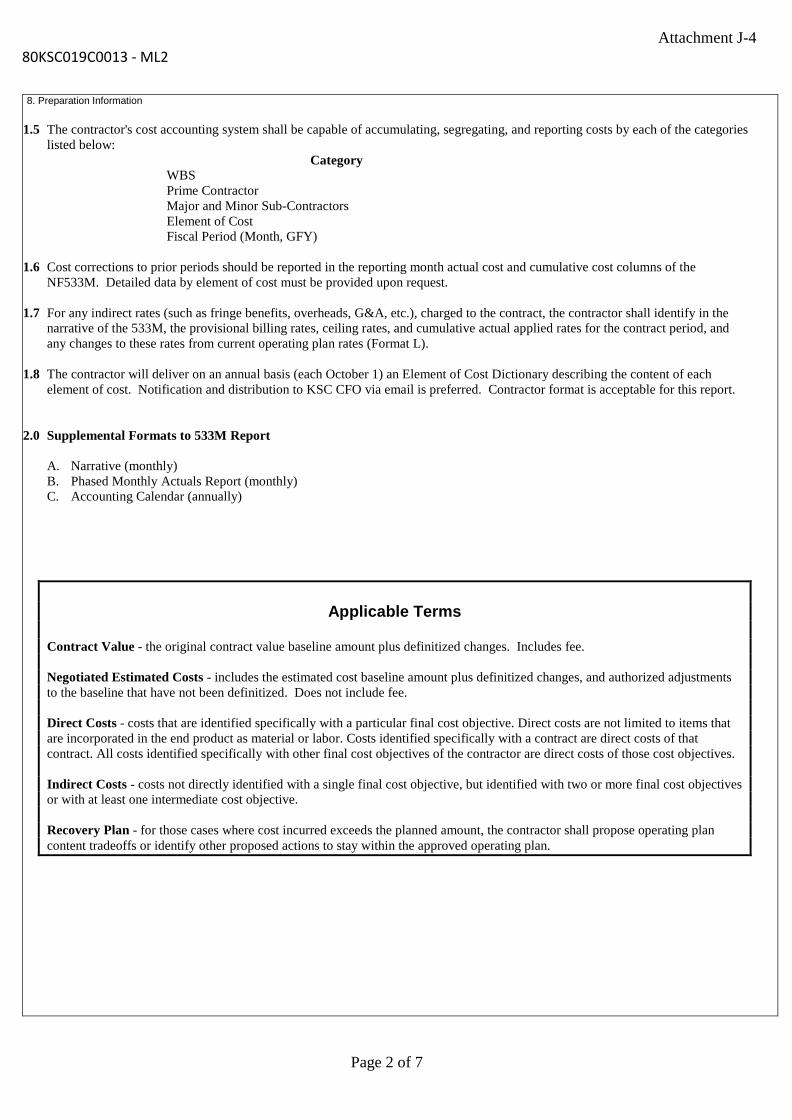
80KSC019C0013 - ML2
Page 2 of 7
8. Preparation Information
1.5 The contractor's cost accounting system shall be capable of accumulating, segregating, and reporting costs by each of the categories listed below:
Category WBS Prime Contractor Major and Minor Sub-Contractors Element of Cost Fiscal Period (Month, GFY)
1.6 Cost corrections to prior periods should be reported in the reporting month actual cost and cumulative cost columns of the NF533M. Detailed data by element of cost must be provided upon request.
1.7 For any indirect rates (such as fringe benefits, overheads, G&A, etc.), charged to the contract, the contractor shall identify in the narrative of the 533M, the provisional billing rates, ceiling rates, and cumulative actual applied rates for the contract period, and any changes to these rates from current operating plan rates (Format L).
1.8 The contractor will deliver on an annual basis (each October 1) an Element of Cost Dictionary describing the content of each element of cost. Notification and distribution to KSC CFO via email is preferred. Contractor format is acceptable for this report.
2.0 Supplemental Formats to 533M Report
A. Narrative (monthly)B. Phased Monthly Actuals Report (monthly)C. Accounting Calendar (annually)
Applicable Terms
Contract Value - the original contract value baseline amount plus definitized changes. Includes fee.
Negotiated Estimated Costs - includes the estimated cost baseline amount plus definitized changes, and authorized adjustments to the baseline that have not been definitized. Does not include fee.
Direct Costs - costs that are identified specifically with a particular final cost objective. Direct costs are not limited to items that are incorporated in the end product as material or labor. Costs identified specifically with a contract are direct costs of that contract. All costs identified specifically with other final cost objectives of the contractor are direct costs of those cost objectives.
Indirect Costs - costs not directly identified with a single final cost objective, but identified with two or more final cost objectives or with at least one intermediate cost objective.
Recovery Plan - for those cases where cost incurred exceeds the planned amount, the contractor shall propose operating plan content tradeoffs or identify other proposed actions to stay within the approved operating plan.
Attachment J-4

80KSC019C0013 - ML2
Page 3 of 7
Attachment 1: Elements of Cost
Cost Elements Definitions
Straight Time (S/T) Labor Hours/Cost
Reported to NASA as hours are incurred for both prime and major subcontractors. Includes full time and part time employees’ time and cost, not to exceed 40 hours/week.
Overtime (O/T) Labor Hours/Cost
Reported to NASA as hours are incurred both prime and major subcontractors. Includes full time, part time and temporary employees’ time and cost, exceeding 40 hours/week.
Premium Labor Cost
Amount paid for cost associated with labor shift premiums. Includes both prime and major subcontractors.
Equipment Generally reported to NASA when received and accepted by the contractor. Cost is greater than or equal to $5,000 per item.
Depreciation Includes all depreciation cost associated with the capitalization of contractor property. Leases Reported to NASA using a proration over the life of the lease and includes capital and
non-capital equipment. Examples are heavy equipment, machinery, cranes, and laboratory.
Training Related costs are registration fees, airfare, lodging, transportation, meals, auto rental, mileage, certifications, and licenses.
Misc Other Direct Costs
Includes other charges such as contract labor obtained through an outside agency, freight, postage, dues, memberships, subscriptions, courier services.
Travel Reported to NASA as costs are incurred. Examples are airfare, lodging, transportation, auto rental, meals, moving expenses and other incidentals associated with specific travel or permanent relocation requirements.
Subcontracts Actual and estimated costs reported by prime contractors must include subcontractors' incurred costs for the same accounting period. The prime contractor must include in the total cost of each subdivision of work the accrued cost (including fee, if any) of related subcontractor effort. Subcontractors should, therefore, be required to report cost to the prime contractor, using the accrual method of accounting. If the G&A and fee reported by a subcontractor are at the total subcontractor level, these costs must be allocated to specific sub- divisions of work. Data submitted by the subcontractor should be structured similar to the prime contractor's NF533M to enable the prime contractor to properly report to NASA. For major subcontracts, the prime contractor is required to uniquely identify the subcontractor costs reported, the WYEs associated with the subcontracts, and provide this information to the Government.
Materials & Supplies
Examples are supplies such as office supplies, toner cartridges, binders, lumber, electrical, plumbing, paint supplies. Cost is less than $5000 per item.
Leased Vehicle Cost
Cost associated with GSA, commercial vehicles, autos, trucks, vans, tankers, other and includes lease costs, mileage, fuel and maintenance.
Overhead Includes indirect costs directly attributable to the contract. These costs are normally distributed on the basis of direct labor dollars (or hours) or material dollars.
Unfilled Orders Reported as the difference between the cumulative cost incurred to date and the amounts obligated to suppliers and subcontractors.
General & Administrative (G&A)
An accumulation of indirect costs applicable to the direction and control of the contractors’ activities as a whole. This category does not include costs classified as overhead. Commonly included under G&A are costs for officers’ salaries, general and corporate offices, legal and auditing staffs, office supplies, insurance, and taxes. Total cost incurred, exclusive of G&A expenses, is usually used as the basis of distribution to the various cost objectives.
Fee Should be accrued as Estimated Fee until it becomes Earned Fee using a consistent and auditable method to determine the amount. For example: an acceptable method would be to allocate Estimated Fee based on plan data for each month of the award fee period, up to the allowable fee for that period. Estimated fee should be categorized as such until it is earned, at which point it should be deducted from the Estimated Fee line and re-categorized as Earned Fee. Fee should be reported on the NF533M following the "Total Cost w/ G&A" line.
Attachment J-4

80KSC019C0013 - ML2
Page 4 of 7
Attachment 2: NASA Form 533M
Attachment 3: NASA Form 533Q
Attachment J-4
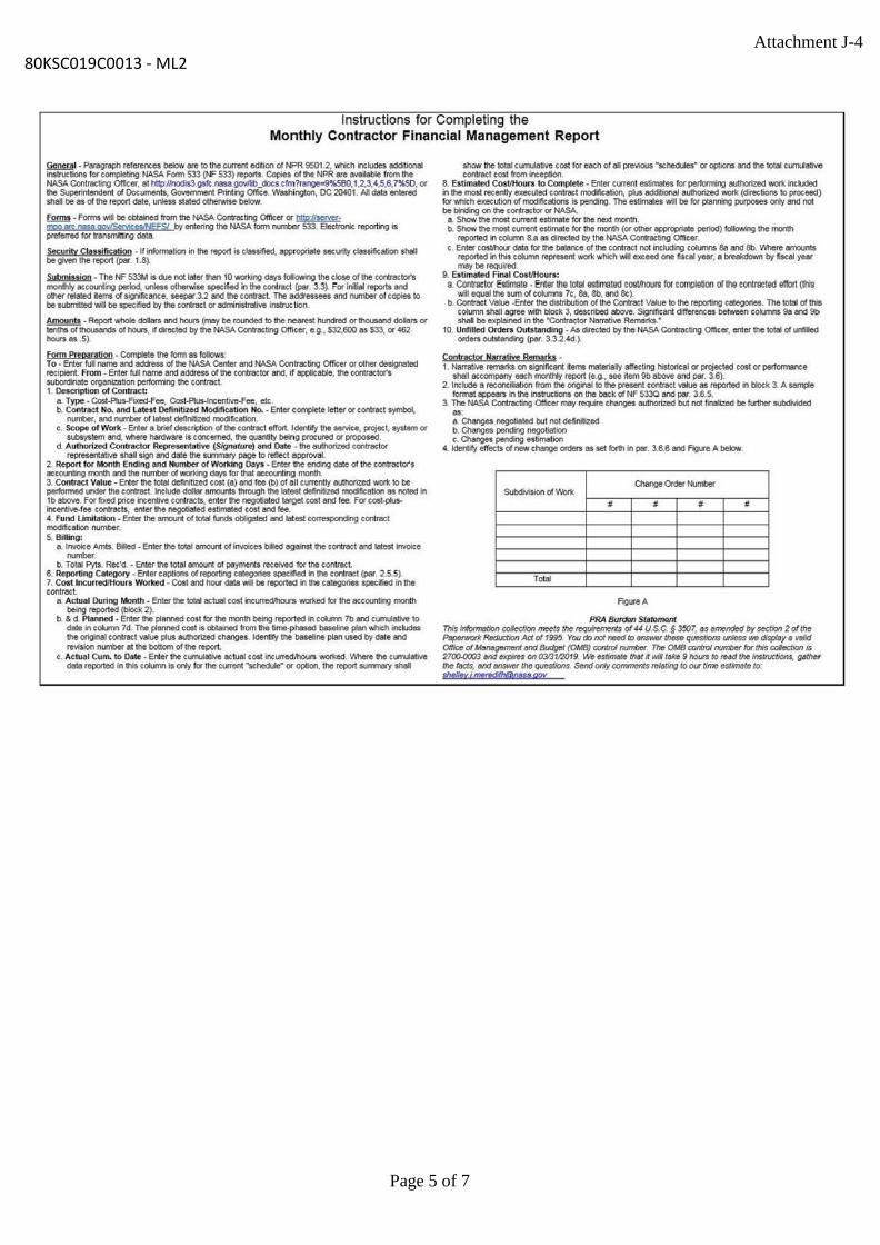
80KSC019C0013 - ML2
Page 5 of 7
Attachment J-4
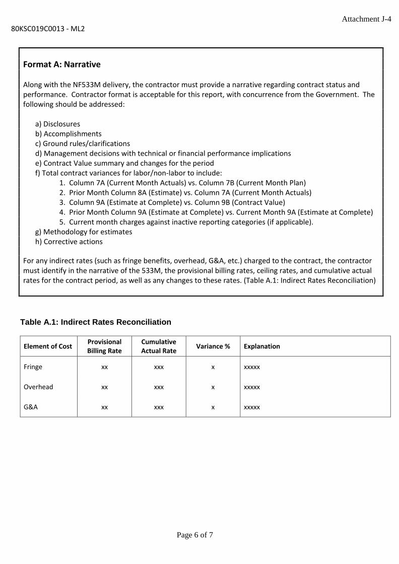
80KSC019C0013 - ML2
Page 6 of 7
Format A: Narrative
Along with the NF533M delivery, the contractor must provide a narrative regarding contract status and performance. Contractor format is acceptable for this report, with concurrence from the Government. The following should be addressed:
a) Disclosuresb) Accomplishmentsc) Ground rules/clarificationsd) Management decisions with technical or financial performance implicationse) Contract Value summary and changes for the periodf) Total contract variances for labor/non-labor to include:
1. Column 7A (Current Month Actuals) vs. Column 7B (Current Month Plan)2. Prior Month Column 8A (Estimate) vs. Column 7A (Current Month Actuals)3. Column 9A (Estimate at Complete) vs. Column 9B (Contract Value)4. Prior Month Column 9A (Estimate at Complete) vs. Current Month 9A (Estimate at Complete)5. Current month charges against inactive reporting categories (if applicable).
g) Methodology for estimatesh) Corrective actions
For any indirect rates (such as fringe benefits, overhead, G&A, etc.) charged to the contract, the contractor must identify in the narrative of the 533M, the provisional billing rates, ceiling rates, and cumulative actual rates for the contract period, as well as any changes to these rates. (Table A.1: Indirect Rates Reconciliation)
Table A.1: Indirect Rates Reconciliation
Element of Cost Provisional Billing Rate
Cumulative Actual Rate Variance % Explanation
Fringe xx xxx x xxxxx
Overhead xx xxx x xxxxx
G&A xx xxx x xxxxx
Attachment J-4

Page 7 of 7
80KSC019C0013 - ML2 Format B: Phased Monthly Actuals Report
Format C: Accounting Calendar
Month Weeks Days Total Hours Non-
Productive Hours
Productive Hours
Oct 4 x xx xxx xxxx Nov 4 x xx xxx xxxx Dec 5 x xx xxx xxxx Jan 4 x xx xxx xxxx Feb 4 x xx xxx xxxx Mar 5 x xx xxx xxxx Apr 4 x xx xxx xxxx May 4 x xx xxx xxxx Jun 5 x xx xxx xxxx Jul 4 x xx xxx xxxx Aug 4 x xx xxx xxxx Sep 5 x xx xxx xxxx
FY Total 52 x xx xxx xxxx
FY Plan/Actual Reporting Category WBS WBS Title Element of Cost Mar Apr May Jun Jul Aug Sep YTD ITD EAC20xx Plan xxxxx xx.xx.xx xxxx Prime S/T Hours x x x x x x x xx xxx xxxx20xx Plan xxxxx xx.xx.xx xxxx Prime O/T Hours x x x x x x x xx xxx xxxx20xx Plan xxxxx xx.xx.xx xxxx Teammate S/T Hours x x x x x x x xx xxx xxxx20xx Plan xxxxx xx.xx.xx xxxx Teammate O/T Hours x x x x x x x xx xxx xxxx20xx Plan xxxxx xx.xx.xx xxxx Total Labor Hours x x x x x x x xx xxx xxxx20xx Plan xxxxx xx.xx.xx xxxx Total WYE x x x x x x x xx xxx xxxx20xx Plan xxxxx xx.xx.xx xxxx Prime S/T Cost x x x x x x x xx xxx xxxx20xx Plan xxxxx xx.xx.xx xxxx Prime O/T Cost x x x x x x x xx xxx xxxx20xx Plan xxxxx xx.xx.xx xxxx Teammate S/T Cost x x x x x x x xx xxx xxxx20xx Plan xxxxx xx.xx.xx xxxx Teammate O/T Cost x x x x x x x xx xxx xxxx20xx Plan xxxxx xx.xx.xx xxxx Fringe x x x x x x x xx xxx xxxx20xx Plan xxxxx xx.xx.xx xxxx Total Labor Cost x x x x x x x xx xxx xxxx20xx Plan xxxxx xx.xx.xx xxxx Minor Subcontractors x x x x x x x xx xxx xxxx20xx Plan xxxxx xx.xx.xx xxxx Materials and Supplies x x x x x x x xx xxx xxxx20xx Plan xxxxx xx.xx.xx xxxx Equipment x x x x x x x xx xxx xxxx20xx Plan xxxxx xx.xx.xx xxxx Travel x x x x x x x xx xxx xxxx20xx Plan xxxxx xx.xx.xx xxxx Training x x x x x x x xx xxx xxxx20xx Plan xxxxx xx.xx.xx xxxx Misc ODCs x x x x x x x xx xxx xxxx20xx Plan xxxxx xx.xx.xx xxxx Total ODCs x x x x x x x xx xxx xxxx20xx Plan xxxxx xx.xx.xx xxxx Overhead x x x x x x x xx xxx xxxx20xx Plan xxxxx xx.xx.xx xxxx G&A x x x x x x x xx xxx xxxx20xx Plan xxxxx xx.xx.xx xxxx Estimated Fee x x x x x x x xx xxx xxxx20xx Plan xxxxx xx.xx.xx xxxx Earned Fee x x x x x x x xx xxx xxxx20xx Plan xxxxx xx.xx.xx xxxx Total Cost Thru G&A x x x x x x x xx xxx xxxx20xx Plan xxxxx xx.xx.xx xxxx Total cost with Fee x x x x x x x xx xxx xxxx
Attachment J-4

80KSC019C0013 - ML2
Page 1 of 2
DATA REQUIREMENT CONTRACT APPLICATION INFORMATION FOR DRL ML2
A. Item No.1.0-6
B. Line Item Title:
Integrated Program Management Report (IPMR)
C. Opr.
LX-B
D. Type
3
E. Inspect/Accept
6
F. Freq.
MO
G. Initial Sub.
See Block J
H. As Of Date
See Block J
J. Remarks:
The first submission (IPMR Formats 1, 3, and 5) is due 10 working days after the end of the second full accounting period following contract award. Initial submission of Format 6 is due 30 days after contract award.
Submission Frequency: Monthly. Formats 1, 3, 5 and 6 by the 10th working day after contractor accounting period closes. Format 7 annually within 10 working days after the contractor's accounting month end for September.
K. Distribution
OPR/Mail Code: LX-B1 CFO/Mail Code: GG-C-E
COR/Mail Code: LX-D CO/Mail Code: OP-ES
Totals No. Type
4 D
DATA REQUIREMENT DESCRIPTION 1. Title
Integrated Program Management Report (IPMR)
3. Use
The IPMR is the primary means of communicating cost and schedule performance and project health information between the contractor and NASA. The IPMR replaces the Contract Performance Report (CPR) and Integrated Master Schedule (IMS).
4. Date
5. Organization
KSC GG-C-E7. Interrelationship
WBS, 533
6. References
DI-MGMT-81861A, EIA-748(current version at time ofaward)
8. Preparation Information
IPMR Formats (Formats 1, 3, and 5-7) are required. The IPMR must include all data pertaining to all authorized contract work, including both priced and unpriced effort that has been authorized at a not-to-exceed amount in accordance with the Contracting Officer's direction. The contractor must provide IPMRs per DI-MGMT-81861A except as modified in this section. Reconciliation between the NF 533M and IPMR Formats 1 and 3 must be included.
Format 1: Provide reporting at WBS level three, except for WBS 1.0 Project Management and WBS 2.0 Concept Phase which will be reported at WBS level one. Include General and Administrative (G&A) as non-add. Include Cost of Money (COM) as add.
Format 3: Significant differences (values exceeding +/-5%) between the PMB at the beginning and end of each specified period must be explained in Format 5. Use quarterly periods for Block 6, columns (10) through (11), yearly periods for columns (12) through (13), and the remainder of the contract for column (14).
Format 5: Variance analysis is required for all reporting WBS elements as defined below. Additional focus WBSs may be identified by the Government.
1. Current cost and schedule variances exceeding +/- $25,000 and +/-10%2. Cumulative cost and schedule variances exceeding +/-$50,000 and +/-5%3. Variance At Completion exceeding +/-$250,000
If there are no changes to the reportable element problem analysis, expected impacts, or corrective action status, then specify "no changes since the last reported analysis" and reference the IPMR data when the narrative was reported.
KSC FORM 16-246 NS (REV. 02/04) PREVIOUS EDITIONS MAY BE USED
Attachment J-4
2.Number
1.0-6

80KSC019C0013 - ML2
Page 2 of 2
Format 6: Format 6 must be prepared in accordance with DRD 1.0-6 Attachment UFGS 01 32 17.00.20 and in conjunction with DI-MGMT-81861 (latest version) in the event of a conflict regarding schedule detail and formatting, the UFGS specification shall govern. Format 6 must be submitted in the contractor's native schedule electronic file format and the UN/CEFACT XML.
Format 7: Format 7 is required at the same reporting level as Format 1.
Subcontractor Reports: All subcontractor IPMR formats must be included with the Prime's IPMR. IPMRs required from subcontractors must also be provided electronically using the same instructions and electronic formats as for the Prime. In addition, IPMR Format 6 must be provided for all subcontracts greater than 10% of the contract value.
Contractor formats can be substituted for IPMR formats as coordinated and agreed upon by the government. The IPMR must be submitted electronically. The UN/CEFACT XML file must be reported at the control account level. Human readable formats of IPMR Formats 1 and 3 are not required. Report Formats 1, 3, 5 and 7 by dollars. The basis for variance analysis is in dollars.
Attachment J-4

SECTION 01 32 17.00 20 Page 1
************************************************************************** USACE / NAVFAC / AFCEC / NASA UFGS-01 32 17.00 20 (May 2018)
----------------------------------- Preparing Activity: NAVFAC Superseding
UFGS-01 32 17.00 20 (February 2015)
UNIFIED FACILITIES GUIDE SPECIFICATIONS **************************************************************************
SECTION TABLE OF CONTENTS
DIVISION 01 - GENERAL REQUIREMENTS
SECTION 01 32 17.00 20
COST-LOADED NETWORK ANALYSIS SCHEDULES (NAS)
05/18
PART 1 GENERAL
1.1 DEFINITIONS 1.2 SCHEDULE REQUIREMENTS PRIOR TO THE START OF WORK
1.2.1 Preliminary Scheduling Meeting 1.2.2 Project Baseline Schedule
1.3 LOOK AHEAD SCHEDULE 1.3.1 Look Ahead Schedule Requirements
1.4 MONTHLY NETWORK ANALYSIS 1.4.1 Monthly Network Analysis Updates 1.4.2 As-Built Schedule
1.5 CORRESPONDENCE AND TEST REPORTS 1.6 ADDITIONAL SCHEDULING REQUIREMENTS 1.7 SUBMITTALS 1.8 SOFTWARE 1.9 DESIGNATED PROJECT SCHEDULER
1.9.1 Qualifications 1.9.2 Duties
1.10 NETWORK SYSTEM FORMAT 1.10.1 Diagrams 1.10.2 Schedule Activity Properties and Level of Detail
1.10.2.1 Design-Build Schedules 1.10.2.2 Activity Identification and Organization 1.10.2.3 Activity Logic 1.10.2.4 Critical and Near Critical Activity Baseline Limitation 1.10.2.5 Assigned Calendars 1.10.2.6 Activity Categories
1.10.2.6.1 Design Activities 1.10.2.6.2 Pre-construction Activities 1.10.2.6.3 Procurement Activities 1.10.2.6.4 Government Activities 1.10.2.6.5 Construction Quality Management (CQM) Activities 1.10.2.6.6 Construction Activities 1.10.2.6.7 Turnover and Closeout Activities 1.10.2.6.8 Commissioning Activities

SECTION 01 32 17.00 20 Page 2
1.10.2.7 Contract Milestones and Constraints 1.10.2.7.1 Project Start Date Milestones 1.10.2.7.2 Substantial Completion Milestone 1.10.2.7.3 DD-250 Finish Milestone1.10.2.7.4 Projected Completion Milestone 1.10.2.7.5 Contract Completion Date (CCD) Milestone
1.10.2.8 Work Breakdown Structure & Activity Code 1.10.2.8.1 Work Breakdown Structure (WBS) 1.10.2.8.2 Responsibility Code 1.10.2.8.3 Activity Category Code 1.10.2.8.4 Construction Specification Institute (CSI) Masterformat Code 1.10.2.8.5 Drawing Code
1.10.2.9 Anticipated Restricted Delays 1.10.2.10 Cost Loading
1.10.2.10.1 Cost Loading Activities 1.10.2.11.2 Partial Payment
1.10.3 Schedule Software Settings and Restrictions 1.10.4 Required Tabular Reports
1.11 CONTRACT MODIFICATION 1.11.1 Time Impact Analysis (TIA) 1.11.2 No Reservation of Rights
1.12 PROJECT FLOAT
PART 2 PRODUCTS
PART 3 EXECUTION
-- End of Section Table of Contents --

SECTION 01 32 17.00 20 Page 3
************************************************************************** USACE / NAVFAC / AFCEC / NASA UFGS-01 32 17.00 20 (May 2018)
----------------------------------- Preparing Activity: NAVFAC Superseding
UFGS-01 32 17.00 20 (February 2015)
UNIFIED FACILITIES GUIDE SPECIFICATIONS **************************************************************************
SECTION 01 32 17.00 20
COST-LOADED NETWORK ANALYSIS SCHEDULES (NAS) 05/18
**************************************************************************
PART 1 GENERAL
1.1 DEFINITIONS
The cost-loaded Network Analysis Schedule (NAS) is a tool to manage the project, both for Contractor and Government activities. The NAS is also used to report progress, evaluate time extensions, and provide the basis for progress payments. The contractor shall work these requirements in conjunction with the EVMS DRD 1.0-6.
For consistency, when scheduling software terminology is used in this section, the terms in Primavera's scheduling programs are used.
1.2 SCHEDULE REQUIREMENTS PRIOR TO THE START OF WORK
1.2.1 Preliminary Scheduling Meeting
Before finalizing the Project Baseline Schedule, and prior to the start of work, meet with the Contracting Officer to discuss the proposed schedule and the requirements of this section.
1.2.2 Project Baseline Schedule
Submit the Construction Baseline in accordance with the EVM DRD 1.0-6. Government review comments on the Contractor's schedule(s) do not relieve the Contractor from compliance with requirements of the Contract Documents.
The acceptance of a Baseline NAS is a condition precedent to:
a. The Contractor starting construction stage(s) of the contract.
b. Processing Contractor's invoices(s) for construction activities/itemsof work.
c. Review of any schedule updates.
Submittal of the Baseline NAS, and subsequent schedule updates, is understood to be the Contractor's certification that the submitted schedule meets the requirements of the Contract Documents, represents the Contractor's plan on how the work will be accomplished, and accurately reflects the work that has been accomplished and how it was sequenced (as-built logic).
SECTION 01 32 17.00 20 Page 4
1.3 THREE-WEEK LOOK AHEAD SCHEDULE -
1.3.1 Look Ahead Schedule Requirements
The Contractor will partner with the Government for post-award schedule look ahead requirements. Expectations are for a 2- or 3-Week Look Ahead schedule to provide a more detailed day-to-day plan of upcoming work identified on the Project Network Analysis Schedule.
1.4 MONTHLY NETWORK ANALYSIS
1.4.1 Monthly Network Analysis Updates
Meet with Government representatives at monthly intervals to review and agree on the information presented in the updated project schedule. This review shall correspond to the EVMS review specified in DRD 1.0-6. Submit an acceptable, updated schedule to the Government monthly. The Contractor and Government must consent to agree on unit quantities of work completed during the update period. Monthly update schedules must incorporate as-built events as they occurred and provide ongoing status of anticipated finish dates.
Provide the following with each Schedule submittal:
a. Time-Scaled Logic Diagram.
b. Reports listed in paragraph REQUIRED TABULAR REPORTS.
c. Data disks containing the project schedule. Include the back-up native.xer program files.
1.4.2 As-Built Schedule
As a condition precedent to the release of retention and making final payment, submit an "As-Built Schedule," as the last schedule update showing all activities at 100 percent completion. This schedule must reflect the exact manner in which the project was actually constructed.
1.5 CORRESPONDENCE AND TEST REPORTS
Reference Schedule activity IDs that are being addressed in each correspondence (e.g., letters, Requests for Information (RFIs), e-mails, meeting minute items, Production and QC Daily Reports, material delivery tickets, photographs) and test report (e.g., concrete, soil compaction, weld, pressure).
1.6 ADDITIONAL SCHEDULING REQUIREMENTS
References to additional scheduling requirements, including systems to be inspected, tested and commissioned, that are located throughout the remainder of the Contract Documents, are subject to the requirements of this section.
1.7 SUBMITTALS
Refer to the SOW for submittal designations. Designations shall be partnered with the Government during the design charrettes.
1.8 SOFTWARE

SECTION 01 32 17.00 20 Page 5
Prepare and maintain project schedules using Primavera P6 software in a version compatible with Government's current version. Importing data into P6 using data conversion techniques or third party software is cause for rejection of the submitted schedule.
1.10.1 Diagrams
If requested for the monthly updates, provide two 11 by 17 inch hard-copy of Time-scaled Logic Diagram in color and landscape-oriented. Clearly show activities on the longest path. Include the following information for each activity and include accompanying Gantt chart:
a. Activity ID
b. Activity Name
c. Original Duration in Work Days
d. Remaining duration in Work Days
e. Physical Percent Complete
f. Start Date
g. Finish Date
h. Total Float
1.10.2 Schedule Activity Properties and Level of Detail
1.10.2.1 Design-Build Schedules
Logically incorporate design and construction for the entire project in a single schedule. Unless otherwise indicated, the Contractor may begin construction when design is signed, stamped and submitted to the Government via the Contractor's quality control organization. If Government approval is required for any portion of a final signed and sealed design package prior to construction, include that review time in the schedule.
1.10.2.2 Activity Identification and Organization
a. Identify design and construction activities planned for the project andother activities that could impact project completion if delayed in theNAS.
b. Identify administrative type activity/milestones, including allpre-construction submittal and permit requirements prior to demolitionor construction stage.
c. Include times for procurement, Contractor quality control andconstruction, acceptance testing and training in the schedule.
d. Include the Government approval time required for the submittals thatrequire Government Approval prior to construction, as indicated inSection 01 33 00 SUBMITTAL PROCEDURES Section 01 33 00.05 20CONSTRUCTION SUBMITTAL PROCEDURES.
e. Create separate activities for each Phase, Area, Floor Level and

SECTION 01 32 17.00 20 Page 6
Location the activity is occurring.
f. Do not use construction category activity to represent non-work typereference (e.g. Serial Letter, Request for Information) in NAS.Place Non-work reference within the P6 activity details notebook.
Activity categories included in the schedule are specified below.
1.10.2.3 Activity Logic
a. With the exception of the Contract Award and Contract CompletionDate (CCD) milestone activities, activity must not be open-ended;each activity must have predecessor and successor ties.
b. Activities must not have open start or open finish (dangling) logic.
c. Do not use lead or lag logic without Contracting Officer prior approval.
d. Minimize redundant logic ties.
e. Once an activity exists on the schedule it must not be deleted orrenamed to change the scope of the activity and must not be removedfrom the schedule logic without approval from the ContractingOfficer.
(1) While an activity cannot be deleted, where said activity isno longer applicable to the schedule, but must remain withinthe logic stream for historical record, change the activityto a milestone and clearly label "NO LONGER REQUIRED" afterthe activity name. Redistribute accordingly any remainingbudget associated with that activity.
(2) Document any such change in the milestone's "Notebook,"including a date and explanation for the change.
(3) The ID number for a "NO LONGER REQUIRED" activity must notbe re-used for another activity.
1.10.2.4 Critical and Near Critical Activity Baseline Limitation
For P6 settings, critical activities are defined as being on the Longest Path. "Near Critical" is defined as having total float, of up to 14 days more, than the greatest float value found on the Longest Path. Longest Path (Critical) and Near Critical Activities must not make up more than 20 percent of all activity within the Baseline Schedule.
1.10.2.5 Assigned Calendars
All NAS activity must be assigned calendars that reflect required and anticipated non-work days.
1.10.2.6 Activity Categories
1.10.2.6.1 Design Activities
Design activities must include design decision points and design submittal packages, including critical path submittals for Fast Tracked Phases. Review times for design development packages must be included in the schedule.

SECTION 01 32 17.00 20 Page 7
1.10.2.6.2 Pre-construction Activities
Examples of pre-construction activities include, but are not limited to, bond approval, permits, pre-construction submittals and approvals.
Include pre-construction activities that are required to be completed prior to the Contractor starting the demolition or construction stage of work.
1.10.2.6.3 Procurement Activities
Examples of procurement activities include, but are not limited to: Material/equipment submittal preparation, submittal and approval of material/equipment; material/equipment fabrication and delivery, and material/equipment on-site. As a minimum, separate procurement activities must be provided for critical items, long lead items, items requiring Government approval and material/equipment procurement for which payment will be requested in advance of installation. Show each delivery with relationship tie to the Construction Activity specifically for the delivery.
1.10.2.6.4 Government Activities
Government and other agency activities that could impact progress must be clearly identified. Government activities include, but are not limited to; Government approved submittal reviews, Government conducted inspections/tests, environmental permit approvals by State regulators, utility outages, Design Start, Construction Start (including Design/Construction Start for each Fast-Track Phase, and delivery of Government Furnished Material/Equipment.
1.10.2.6.5 Construction Quality Management (CQM) Activities
The Preparatory and Initial Phase meetings for each Definable Feature of Work identified in the Contractor's Quality Control Plan must be included in the Three-Week Look Ahead Schedule. Preparatory and Initial phase meetings are not required in the NAS, but can be represented by a start milestone linked to successor parent Construction Activity. The Follow-up Phase must be represented by the Construction Activities themselves in the NAS.
1.10.2.6.6 Construction Activities
No on-site construction activity may have a duration in excess of 20 working days. Contractor activities must be driven by calendars that reflect Saturdays, Sundays and all Federal Holidays as non-work days, unless otherwise defined in this contract.
1.10.2.6.7 Turnover and Closeout Activities
Include activities or milestones for items on the NAVFAC Red Zone Checklist/POAM that are applicable to this project. As a minimum, include required Contractor testing, required Government acceptance inspections on equipment, Pre-Final Inspection, Punch List Completion, Final Inspection and Acceptance. Add an unconstrained start milestone for the initial NAVFAC Red Zone - Facility Turnover Planning Meeting at approximately 75 percent construction contract completion or six months prior to Contract Completion Date (CCD), whichever is sooner.
1.10.2.6.8 Commissioning Activities

SECTION 01 32 17.00 20 Page 8
Include in the baseline schedule activities and milestones associated with Commissioning.
a. Identify the general area or location(s) of systems for CommissioningInspection and Testing
b. Incorporate into the baseline schedule time periods for Governmentsubmittal review
1.10.2.7 Contract Milestones and Constraints
1.10.2.7.1 Project Start Date Milestones
Include as the first activity on the schedule a start milestone titled "Contract Award," which must have a Mandatory Start constraint equal to the Contract Award Date.
1.10.2.7.2 Substantial Completion Milestone
Include an unconstrained finish milestone on the schedule titled "Substantial Completion." Substantial Completion is defined as the point in time the Government would consider the project ready for beneficial occupancy wherein by mutual agreement of the Government and Contractor, Government use of the facility is allowed while construction access continues in order to complete remaining items (e.g. punch list and other close out submittals). Include a separate Substantial Completion Milestone for each phase if the contract requires construction to be completed in phases.
1.10.2.7.3 DD-250 Finish Milestone
Add unconstrained finish milestone, titled "DD-250" and scheduled 30 calendar days prior to Substantial Completion.
1.10.2.7.4 Projected Completion Milestone
Include an unconstrained finish milestone on the schedule titled "Projected Completion." Projected Completion is defined as the point in time all contract requirements are complete and verified by the Government with a successful Final Inspection. This milestone must have the Contract Completion Date (CCD) milestone as its only successor.
1.10.2.7.5 Contract Completion Date (CCD) Milestone
Last schedule entry must be an unconstrained finish milestone titled "Contract Completion (CCD: DD-MM-YY)." DD-MM-YYYY is the current contract completion date at data date, day-month-year corresponding to P6 Must Finish Date. NAS milestone updates of Project Completion finish date for longest path must reflect calculated float as positive or negative based on CCD. Calculation of schedule updates must be such that if the finish ofthe "Projected Completion" milestone falls after the contract completiondate, then negative float is calculated on the longest path. If the finishof the "Projected Completion" milestone falls before the contractcompletion date, the float calculation must reflect positive float on thelongest path.
1.10.2.8 Work Breakdown Structure & Activity Code
At a minimum, establish a lower level Work Breakdown Structure (WBS) as required and provide activity codes identified per the following:
SECTION 01 32 17.00 20 Page 9
1.10.2.8.1 Work Breakdown Structure (WBS)
Group all activities and milestones within appropriate WBS categories.
1.10.2.8.2 Responsibility Code
All activities in the project schedule must be identified with the party responsible for completing the task. Activities must not belong to more than one responsible party.
1.10.2.8.3 Activity Category Code
Provide user defined "CAT" codes for Project Level activity codes. Use the following codes:
a. Assign "Procure" to Procurement type activity
b. Assign "Construct" Construction type activity
c. Assign "Close Out" to dedicated Commissioning, Testing & Close Out typeactivity.
d. Assign "Other" to other activity not otherwise designated.
1.10.2.8.4 Construction Specification Institute (CSI) Masterformat Code
Identify all activities in the project schedule with its respective Specification Section number. Activities must not belong to more than one Section number. If an activity does not have an applicable CSI Code (e.g. Mobilize), the code must be "0000".
1.10.2.8.5 Drawing Code
Identify all activities in the project schedule with its respective Drawing Code. The Drawing Code is the Sheet Number on the primary project drawing which indicates work to be performed. If an activity does not have an applicable Drawing Code (e.g. Mobilize), the code must be "0000".
1.10.2.10 Anticipated Restricted Delays
Down-days and No-dig days specified in the contract shall be included on the schedule.
1.10.2.11 Cost Loading
The Project Network Analysis Schedule (NAS) must be cost-loaded and will provide the basis for progress payments. Earned Value Reports shall be generated per the Contractors established EVM system and as specified in DI-MGMT-81861A. Use the Critical Path Method (CPM) and the PrecedenceDiagram Method (PDM) to satisfy time and cost applications.
1.10.2.11.1 Cost Loading Activities
Assign Material and Equipment Costs, for which payment will be requested in advance of installation, to their respective procurement activity (i.e., the material/equipment on-site activity). Assign cost for material/equipment, paid for after installation; labor; and construction equipment to their respective Construction Activities. Provide breakdown

SECTION 01 32 17.00 20 Page 10
of definable features of work for cost loaded activities comprising Mobilization and De-Mobilization (Lump sum not allowed). Refer to DI-MGMT-81861A for Level of Effort (LOE) line items.
1.10.3 Schedule Software Settings and Restrictions
a. Activity Constraints: Date/time constraint(s), other than thoserequired by the contract, are not allowed unless accepted by theContracting Officer. Identify any constraints proposed and provide anexplanation for the purpose of the constraint in the Narrative Reportas described in paragraph REQUIRED TABULAR REPORTS.
b. Default Progress Data Disallowed: Actual Start and Actual Finish dateson the CPM schedule must match the dates on the Contractor QualityControl and Production Reports.
c. Software Settings: Handle schedule calculations and Out-of-Sequenceprogress (if applicable) through Retained Logic, not Progress Override.
Show all activity durations and float values in days. Show activityprogress using Remaining Duration. Set default activity type to "Task Dependent".
d. At a minimum, include the following settings and parameters in P6Schedule preparation:
(1) General: Define or establish Calendars and Activity Codes at the"Project" level, not the "Global" level.
(2) Admin Drop-Down Menu, Admin Preferences, Time Periods Tab:
(a) Set time periods for P6 to 8.0 Hours/Day, 40.0 Hours/Week,172.0 Hours/Month and 2000.0 Hours/Year.
(b) Use assigned calendar to specify the number of work hours foreach time period: Must be checked.
(3) Admin Drop-Down Menu, Admin Preferences, Earned Value Tab:
(a) Earned Value Calculation: Use "Budgeted values with currentdates".
(4) Project Level, Dates Tab:
(a) Set "Must Finish By" date to "Contract Completion Date", andset "Must Finish By" time to 05:00pm.
(5) Project Level, Defaults Tab:
(a) Duration Type: Set to "Fixed Duration & Units".
(b) Percent Complete Type: Set to "Physical".
(c) Activity Type: Set to "Task Dependent".
(d) Calendar: Set to "Standard 5 Day Workweek". Calendar mustreflect Saturday, Sunday and all Federal holidays as non-work days.
Alternative calendars may be used with Contracting Officer approval.
(6) Project Level, Calculations Tab:

SECTION 01 32 17.00 20 Page 11
(a) Activity percent complete based on activity steps: Must beChecked.
(b) Reset Remaining Duration and Units to Original: Must beChecked.
(c) Subtract Actual from At Completion: Must be Checked.
(d) Recalculate Actual units and Cost when duration percentcomplete changes: Must be Checked.
(e) Link Actual to Date and Actual This Period Units and Cost:Must be Checked.
(f) Price/Unit: Set to "$1/h".
(g) Update units when costs change on resource assignments: Must
Be Unchecked.
(7) Project Level, Settings Tab:
(a) Define Critical Activities: Check "Longest Path".
(8) Work Breakdown Structure Level, Earned Value Tab:
(a) Technique for Computing Performance Percent Complete:"Activity percent complete" is selected.
(b) Technique for Computing Estimate to Complete (ETC): "PF = 1"is selected.
1.10.4 Required Tabular Reports
This section shall be worked in conjunction with the requirements in DRD 1.0-6 and DI-MGMT-81861A. Include the following reports with the Baseline, Monthly Update and any other required schedule submittals:
a. Log Report: P6 Scheduling/Leveling Report.
b. Narrative Report: Identify and justify:
(1) Progress made in each area of the project;
(2) Longest Path;
(3) Date/time constraint(s), other than those required by the contract
(4) Listing of all changes made between the previous schedule andcurrent updated schedule include: added or deleted activities,original and remaining durations for activities that have notstarted, logic (sequence constraint lag/lead), milestones, plannedsequence of operations, longest path, calendars or calendarassignments, and cost loading;
(5) Any decrease in previously reported activity Earned Amount;
(6) Pending items and status thereof, including permits, changesorders, and time extensions;

SECTION 01 32 17.00 20 Page 12
(7) Status of Contract Completion Date and interim milestones;
(8) Current and anticipated delays (describe cause of delay andcorrective actions(s) and mitigation measures to minimize);
(9) Description of current and potential future schedule problem areas.
Each entry in the narrative report must cite the respective Activity ID and Activity Name, the date and reason for the change, and description of the change.
c. Earned Value Report: Derive from and correspond to P6 cost loadedschedule. List all activities having a budget amount cost loaded.Compile total earnings on the project from notice to proceed to currentprogress payment request. Show current budget, previous physicalpercent complete, to-date physical percent complete, previous earnedvalue, to-date earned value and cost to complete on the report for eachactivity.
d. Schedule Variance Control (SVC) Diagram: With each schedulesubmission, provide a SVC diagram showing 1) Cash Flow S-Curvesindicating planned project cost based on projected early and lateactivity finish dates and 2) Earned Value to-date. Revise Cash FlowS-Curves when the contract is modified, or as directed by theContracting Officer.
1.11 CONTRACT MODIFICATION
1.11.1 Time Impact Analysis (TIA)
Submit a Time Impact Analysis with each cost and time proposal for a proposed change. TIA must illustrate the influence of each change or delay on the Contract Completion Date or milestones. No time extensions will be granted nor delay damages paid unless a delay occurs which consumes all available Project Float, and extends the Projected Completion beyond the Contract Completion Date.
a. Each TIA must be in both narrative and schedule form. The narrativemust define the scope and conditions of the change; provide start andfinish dates of impact, successor and predecessor activity to impactperiod, responsible party; describe how it originated, and how itimpacts the schedule. The schedule submission must consist of threenative files:
(1) Fragnet used to define the scope of the changed condition
(2) Most recent accepted schedule update as of the time of theproposal or claim submission that has been updated to show allactivity progress as of the time of the impact start date.
(3) The impacted schedule that has the fragnet inserted in the updatedschedule and the schedule "run" so that the new completion date isdetermined.
b. For claimed as-built project delay, the inserted fragnet TIA methodmust be modified to account for as-built events known to occur afterthe data date of schedule update used.
c. All TIAs must include any mitigation, and must determine theapportionment of the overall delay assignable to each individual delay.Apportionment must provide identification of delay type and
SECTION 01 32 17.00 20 Page 13
classification of delay by compensable and non-compensable events.The associated narrative must clearly describe analysis methodology used, and the findings in a chronological listing beginning with the earliest delay event.
(1) Identify and classify types of delay defined as follows:
(a) Force majeure delay (e.g. weather delay): Any delay eventcaused by something or someone other than the Government or theContractor, or the risk of which has not been assigned solely tothe Government or the Contractor. If the force majeure delay ison the longest path, in absence of other types of concurrentdelays, the Contractor is granted an extension of contract time,classified as a non-compensable event.
(b) A Contractor-delay: Any delay event caused by the Contractor,or the risk of which has been assigned solely to the Contractor. Ifthe contractor-delay is on the longest path, in absence of othertypes of concurrent delays, Contractor is not granted extension ofcontract time, and classified as a non-compensable event. Where absent other types of delays, and having impact to project completion, Contractor must provide to Contracting Officer a Corrective Action Plan identifying plan to mitigate delay.
(c) A Government-delay: Any delay event caused by the Government,or the risk of which has been assigned solely to the Government. Ifthe Government-delay is on the longest path, in absence of othertypes of concurrent delays, the Contractor is granted an extensionof contract time, and classified as a compensable event.
(2) Functional theory must be used to analyze concurrent delays, where:separate delay issues delay project completion, do not
necessarily occur at same time, rather occur within same monthlyschedule update period at minimum, or within same as-built periodunder review. If a combination of functionally concurrent delaytypes occurs, it is considered Concurrent Delay, which is definedin the following combinations:
(a) Government-delay concurrent with contractor-delay: excusabletime extension, classified non-compensable event.
(b) Government-delay concurrent with force majeure delay:excusable time extension, classified non-compensable event.
(c) Contractor-delay concurrent with force majeure delay:excusable time extension, classified non-compensable event.
(3) Pacing delay reacting to another delay (parent delay) equally ormore critical than paced activity must be identified prior topacing. Contracting Officer will notify Contractor prior topacing. Contractor must notify Contracting Officer prior topacing. Notification must include identification of parent delayissue, estimated parent delay time period, paced activity(s)identity, and pacing reason(s). Pacing Concurrency is defined asfollows:
(a) Government-delay concurrent with contractor-pacing: excusabletime extension, classified compensable event.
(b) Contractor-delay concurrent with Government-pacing:

SECTION 01 32 17.00 20 Page 14
inexcusable time extension, classified non-compensable event
d. Submit Data disks containing the narrative and the source schedulefiles used in the time impact analysis.
e. All as-built and known planned activity must be included in NAS. Addcost loading or change Contract Completion Date to NAS in accordance toconformed contract modifications issued prior to Data Date of NASupdate.
1.11.2 No Reservation of Rights
All direct costs, indirect cost, and time extensions will be negotiated and made full, equitable and final at the time of modification issuance.
1.12 PROJECT FLOAT
Project Float is the length of time between the Contractor's Projected Completion Milestone and the Contract Completion Date Milestone. Project Float available in the schedule will not be for the exclusive use of either the Government or the Contractor.
The use of Resource Leveling or other techniques used for the purpose of artificially adjusting activity durations to consume float and influence critical path is prohibited.
PART 2 PRODUCTS
Not used.
PART 3 EXECUTION
Not used.
-- End of Section --

80KSC019C0013 - ML2
DATA REQUIREMENT CONTRACT APPLICATION INFORMATION FOR DRL ML2
A. Item No.1.0-7
B. Line Item Title:
Contract Work Breakdown Structure (CWBS) Dictionary
C. Opr.
LX-B
D. Type
3
E. Inspect/Accept
6
F. Freq.
RT
G. Initial Sub.
At contract start
H. As Of Date
See Block J
J. Remarks:
Work Breakdown Structure (WBS) and WBS Dictionary will be made available to the Government in electronic, on-line format; and must be updated within 30 days after any approved changes to the WBS structure. The contractor shall submit type “D”, electronic copies that are compatible with Microsoft Office software.
K. Distribution
OPR/Mail Code: LX-B1 CFO/Mail Code: GG-C-E
COR/Mail Code: LX-D CO/Mail Code: OP-ES
Totals No. Type
4 D
DATA REQUIREMENT DESCRIPTION 1. Title
Contract Work Breakdown Structure (CWBS) Dictionary
3. Use
To provide insight into the WBS, which serves as the framework for contract planning, budgeting, cost recording and schedule reporting.
4. Date
5. Organization
KSC7. Interrelationship
533, IPMR
6. References
SOW
8. Preparation Information
The contractor must coordinate the establishment of the WBS with the Government for approval. The contractor will update and maintain the WBS. The contractor will develop, update, and maintain a WBS Dictionary that adequately describes the work content being performed within each WBS down to the lowest reportable level. The WBS dictionary must include the following for each WBS element:
a) WBS element numberb) WBS element titlec) WBS element content descriptiond) SOW section number
Contractor format is acceptable.
KSC FORM 16-246 NS (REV. 02/04) PREVIOUS EDITIONS MAY BE USE
Attachment J-4
2.Number
1.0-7

80KSC019C0013 - ML2
DATA REQUIREMENT CONTRACT APPLICATION INFORMATION FOR DRL ML2
A. Item No.1.0-8
B. Line Item Title:
Fixed Price Proposal
C. Opr.
OP
D. Type
1
E. Inspect/Accept
3
F. Freq.
OT
G. Initial Sub.
90% Design Milestone
H. As Of Date
By 3/2/2020
J. Remarks:
Type “A”: Regular
Type “D”: Electronic submittal. Product shall be compatible with Microsoft Office suite of software.
K. Distribution
OP-ES
Totals No. Type
1 A 1 D
DATA REQUIREMENT DESCRIPTION 1. Title
Fixed Price Proposal
2.Number
1.0-8
3. Use
Sole source acquisition for providing certified cost and pricing data outlined in FAR 15.403-4 and none of the exceptions in 15.403-1 apply.
4. Date
5. Organization
7. Interrelationship 6. References
8. Preparation Information
1) Submit in accordance with FAR 15.403-5(b)(1)2) Provide certificate of current cost or pricing data (FAR 15.406-2)3) Proposal must be submitted following the requirements outlined in FAR 15.408, Table 15-2, Instructions for SubmittingCost/Pricing Proposals when Certified Cost or Pricing Data are Required.4) Include subcontractor required certified cost and pricing data as outlined in FAR 15.404-3.
The Government will provide a Model Contract to the Contractor one month prior to the Integrated Critical Design Review.
KSC FORM 16-246 NS (REV. 02/04) PREVIOUS EDITIONS MAY BE USED
Appendix

80KSC019C0013 - ML2
DATA REQUIREMENT CONTRACT APPLICATION INFORMATION FOR DRL ML2
A. Item No.1.0-9
B. Line Item Title:
Earned Value Management System (EVMS) Implementation Plan
C. Opr.
LX-B
D. Type
3
E. Inspect/Accept
2
F. Freq.
OT
G. Initial Sub.
30 days after contract award
H. As Of Date
See Block G
J. Remarks:
The contractor shall submit type “D”, electronic copies that are compatible with Microsoft Office software.K. Distribution
OPR/Mail Code: LX-B1 CFO/Mail Code: GG-C-E
COR/Mail Code: LX-D CO/Mail Code: OP-ES
Totals
No. Type
4 D
DATA REQUIREMENT DESCRIPTION 1. Title
Earned Value Management System (EVMS) Implementation Plan
2.Number
1.0-9
3. Use
The EVMS Plan will be used by the Government to evaluate the contractor’s plan for implementing an Earned Value Management System (EVMS).
4. Date
5. Organization
KSC GG-C-E7. Interrelationship
IPMR
6. References
NFS 1834.201, NFS 1852.234-1, EIA-748 (current version at time of award)
8. Preparation Information
If the contractor proposes to use an EVM system that has not been determined by the cognizant Federal agency (NASA or DCMA) to be in compliance with the guidelines in the Electronic Industries Alliance Standard 748, Earned Value Management Systems (EIA-748), the contractor will submit a plan for compliance to EVMS guidelines to the Government for approval.
The plan shall:
1) Describe the EVMS the contractor intends to use in performance of the contract;2) Distinguish between the contractor’s existing management system and proposed modifications;3) Provide a matrix that correlates each guideline in EIA-748 (current version at time of award) to the corresponding process
in the contractor’s written management procedures;4) Describe the proposed procedure for application of the EVMS requirements to subcontractors;5) Describe how the contractor will ensure EVMS compliance for each subcontractor subject to flowdown requirements in
NFS 1834.201 whose EVMS has not been recognized by the cognizant Federal agency (NASA or DCMA) as compliant;6) Provide documentation describing the process and results, including Government participation, of any third-party or self-
evaluation of the system’s compliance with the EVMS guidelines; and7) If the contractor’s proposal, including options is valued at $100 million or more, provide a schedule of events leading up to
formal compliance/validation review and Government acceptance of the Contractor’s EVMS. Guidance can be found inthe Department of Defense Earned Value Management Interpretation Guide as well as in the National Defense IndustrialAssociation (NDIA) Integrated Program Management Division (IPMD) Earned Value Management System AcceptanceGuide.
KSC FORM 16-246 NS (REV. 02/04) PREVIOUS EDITIONS MAY BE USED
Attachment J-4

80KSC019C0013 - ML2
Page 1 of 1
DATA REQUIREMENT CONTRACT APPLICATION INFORMATION FOR DRL ML2 A. Item No.
1.0-10B. Line Item Title:
Phased Negotiated Estimated Cost Report
C. Opr.
GG-C-E
D. Type
3
E. Inspect/Accept
6
F. Freq.
SA
G. Initial Sub.
See Block J
H. As Of Date
See Block J
J. Remarks:
The Phased Negotiated Estimated Cost (NEC) Report is due 10 working days after the close of each award fee period of performance. The Report shall be compatible with Microsoft Excel software.
K. Distribution
OPR/Mail Code: GG-C-E PP&C/Mail Code: LX-B1
COR/Mail Code: LX-D CO/Mail Code: OP-ES
Totals No. Type
4 D
DATA REQUIREMENT DESCRIPTION 1. Title
Phased Negotiated Estimated Cost Report
3. Use
To establish NEC and to compare NEC to actual contract cost performance for Award Fee evaluation.
4. Date
5. Organization
KSC7. Interrelationship
WBS, 533, IPMR
6. References
8. Preparation Information
The NEC report shall:1. Include all contract modifications and any undefinitized contract actions (UCAs) that increase or decrease the NEC.2. Provide plan, actual, and variance data for all elements of cost identified in DRD 1.0-5, Financial Management Reports
(533).3. Provide explanations for each element of cost with a variance exceeding +/-5%.4. Provide explanations for any CWBS with a variance exceeding +/- $50,000 and +/-5%.5. Include a classification of within or not within the contractor’s control for each variance explanation provided.
Contractor format is acceptable, as coordinated and agreed upon by the government.
KSC FORM 16-246 NS (REV. 02/04) PREVIOUS EDITIONS MAY BE USED
Attachment J-4
2.Number
1.0-10