mode-i metal-composite interface fracture testing for
TRANSCRIPT
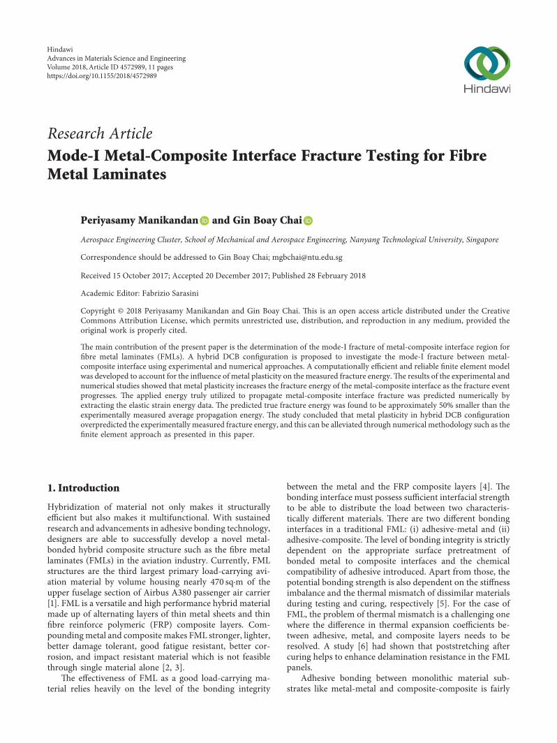
Research ArticleMode-I Metal-Composite Interface Fracture Testing for FibreMetal Laminates
Periyasamy Manikandan and Gin Boay Chai
Aerospace Engineering Cluster School of Mechanical and Aerospace Engineering Nanyang Technological University Singapore
Correspondence should be addressed to Gin Boay Chai mgbchaintuedusg
Received 15 October 2017 Accepted 20 December 2017 Published 28 February 2018
Academic Editor Fabrizio Sarasini
Copyright copy 2018 Periyasamy Manikandan and Gin Boay Chai -is is an open access article distributed under the CreativeCommons Attribution License which permits unrestricted use distribution and reproduction in any medium provided theoriginal work is properly cited
-e main contribution of the present paper is the determination of the mode-I fracture of metal-composite interface region forfibre metal laminates (FMLs) A hybrid DCB configuration is proposed to investigate the mode-I fracture between metal-composite interface using experimental and numerical approaches A computationally efficient and reliable finite element modelwas developed to account for the influence of metal plasticity on the measured fracture energy-e results of the experimental andnumerical studies showed that metal plasticity increases the fracture energy of the metal-composite interface as the fracture eventprogresses -e applied energy truly utilized to propagate metal-composite interface fracture was predicted numerically byextracting the elastic strain energy data -e predicted true fracture energy was found to be approximately 50 smaller than theexperimentally measured average propagation energy -e study concluded that metal plasticity in hybrid DCB configurationoverpredicted the experimentally measured fracture energy and this can be alleviated through numerical methodology such as thefinite element approach as presented in this paper
1 Introduction
Hybridization of material not only makes it structurallyefficient but also makes it multifunctional With sustainedresearch and advancements in adhesive bonding technologydesigners are able to successfully develop a novel metal-bonded hybrid composite structure such as the fibre metallaminates (FMLs) in the aviation industry Currently FMLstructures are the third largest primary load-carrying avi-ation material by volume housing nearly 470 sqmiddotm of theupper fuselage section of Airbus A380 passenger air carrier[1] FML is a versatile and high performance hybrid materialmade up of alternating layers of thin metal sheets and thinfibre reinforce polymeric (FRP) composite layers Com-poundingmetal and composite makes FML stronger lighterbetter damage tolerant good fatigue resistant better cor-rosion and impact resistant material which is not feasiblethrough single material alone [2 3]
-e effectiveness of FML as a good load-carrying ma-terial relies heavily on the level of the bonding integrity
between the metal and the FRP composite layers [4] -ebonding interface must possess sufficient interfacial strengthto be able to distribute the load between two characteris-tically different materials -ere are two different bondinginterfaces in a traditional FML (i) adhesive-metal and (ii)adhesive-composite -e level of bonding integrity is strictlydependent on the appropriate surface pretreatment ofbonded metal to composite interfaces and the chemicalcompatibility of adhesive introduced Apart from those thepotential bonding strength is also dependent on the stiffnessimbalance and the thermal mismatch of dissimilar materialsduring testing and curing respectively [5] For the case ofFML the problem of thermal mismatch is a challenging onewhere the difference in thermal expansion coefficients be-tween adhesive metal and composite layers needs to beresolved A study [6] had shown that poststretching aftercuring helps to enhance delamination resistance in the FMLpanels
Adhesive bonding between monolithic material sub-strates like metal-metal and composite-composite is fairly
HindawiAdvances in Materials Science and EngineeringVolume 2018 Article ID 4572989 11 pageshttpsdoiorg10115520184572989
well understood and the testing procedures to evaluate theirfracture properties are fairly standardized However this isnot the case for evaluating dissimilar material joints likemetal-composite interface Furthermore plastic yielding ispredominately sensitive in the DCB sample having thinmetal adherent and may attenuate the crack propagation infracture test thereafter [7] Such plasticity can result inabnormally high values of fracture toughness and it isnecessary to account for its influence in order to obtain thetrue magnitude of the fracture energy So far in literatureresearchers had employed three different approaches toaccount for the plasticity effects (i) experimental approachusing thick metal doublers to attenuate plastic flow [6 8] (ii)theoretical approach [9] and (iii) finite element approach[7] In the last two approaches efforts were made to estimatethe fraction of plastically absorbed energy from the overallinternal strain energy
Reeder et al [8] portrayed the method of bondingdoublers to thin substrates in a manner to avoid plasticdeformation or premature adherent failure due to bendingbefore the interface delamination initiate -e standardIrwinndashKies fracture energy equation was revised for thesamples having bonded doublers for all three modesof fracture Vlot and Van Ingen [6] utilized a similarconcept to evaluate the delamination fracture energy ofmetal-composite interface of FML To achieve stable de-lamination propagation in the mode-I test using thedouble cantilever beam (DCB) geometry the transversedisplacement of loading platen was stopped at every in-terval when there exists a delamination growth and stayeduntil the load magnitude leveled off Lawcock et al [10]followed the standard testing procedure of metallic jointsto evaluate mode-I fracture energy of FML assuming thatthe volume fraction of the composite in the consideredDCB geometry is negligibly small compared to the metalvolume
Reyes et al [11] evaluated the mode-I mode-II andmixed-mode fracture energy of metal-composite interface ofFML using a single cantilever beam (SCB) a double endnotched flexure and a modified mixed-mode flexure ge-ometry respectively Using the SCB geometry stable in-terface crack propagation without causing plastic yielding ofmetal sheet would become feasible However if the fractureenergy of the adhesive material is far larger than the yieldingstress of the metal sheet this method could enforce morechallenge to initiate interface crack growth
-e aim of the present paper is to investigate the mode-Ifracture energy evaluation of metal-composite joints inorder to understand the interface crack growth in FML thatinvolves the influence of the plastic yielding in thin metalsheets Finite element approach was utilized to estimate theamount of energy dissipated through plastic deformation-e robustness of the developed numerical model wasvalidated by comparing the fracture test results of mono-lithic composite-composite sample with those obtained fromthe numerical study Such comparison also explores theinfluence of plasticity effects and allows one to quantitativelyestimate how far the fracture energy magnitude has beenaltered due to such additional irreversible deformation
2 Materials and Test Methodology
In this section the mode-I fracture test geometry and themethodology used in the study are described Subsequentlythe investigation of mode-I fracture behavior of composite-composite and metal-composite joints are presented andsome conclusive remarks are narrated in the final section
21 Materials Aluminum alloy Al 2024-0 L-530 8-harnesssatin weave 7781 glass epoxy prepreg and Redux 335Kadhesive film are the materials used to fabricate the adhe-sively bonded fibre-metal laminated samples investigated inthis study Before bonding the aluminum alloy bondedsurfaces were abraded using 320 grit size sand paper cleanedwith acetone solvent and appropriately surface treated ina motive to promote good chemical linkage betweenaluminum-adhesive-composite interface
Metal-composite layers of designated stacking werelaminated and bonded with the single layer of adhesive filmStacked laminates were cured in accordance with thecomposite manufacturer data sheet using an autoclavechamber under 3 bar and 120degC in the presence of vacuum-e cured laminates were cut to the required dimensionwithout disturbing the adhesively bonded interface usinga high-speed water jet cutter and quality checks werecarefully carried out under the optical microscope
22 Experimental Tests In total three different configura-tions of DCB tests were experimented to investigate themode-I fracture behavior of metal-composite adhesive in-terface fracture growth -ey are as follows
(i) -ick metal doublers bonded with thin compositeadherent M-C-M configuration
(ii) Monolithic composite adherents with in situ epoxymatrix adhesive interface C-C configuration
(iii) Hybrid geometry with firmly bonded metal-composite adherent as one arm and monolithiccomposite adherent as another arm C-M-Cconfiguration
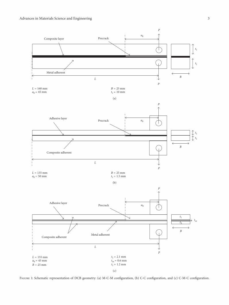
Schematic representation of above listed configurationsand relevant dimensions are shown in Figures 1(a)ndash1(c)respectively Samples were tested at a rate of 3mmminusing a universal testingmachine Magnitude of load P crosshead displacement δ and crack length a were recordedduring both crack initiation and instant propagation
-e fracture energy for M-C-M configuration is evalu-ated using the following guidelines of ASTM D3833 as-suming that the composite layer is very thin compared tothick aluminum doublers [10] -e equation of mode-Ifracture energy GI is given by
GI 4P2
EB2t213a
2o + t
211113960 1113961 (1)
where E B and t1 are Youngrsquos modulus width andthickness of the aluminum adherends
2 Advances in Materials Science and Engineering
L = 160 mma0 = 45 mm
B = 25 mmt1 = 10 mm
Composite layer
Metal adherent
a0
L
P
P
Precrack
t1
t1
B
(a)
a0
t1t1
L
P
P
Adhesive layerPrecrack
Composite adherent
B
L = 135 mma0 = 50 mm
B = 25 mmt1 = 15 mm
(b)
a0
t1t2
tm
L
P
P
Adhesive layerPrecrack
Composite adherent
B
L = 155 mma0 = 45 mmB = 25 mm
t1 = 21 mmtm = 06 mmt1 = 12 mm
Metal adherent
(c)
Figure 1 Schematic representation of DCB geometry (a) M-C-M conguration (b) C-C conguration and (c) C-M-C conguration
Advances in Materials Science and Engineering 3
While for the C-C and C-M-C congurations the valueof fracture energy is ascertained using the IrwinndashKiesequation [12] given by
GI P2
2BmiddotdC
da (2)
where C δP is the specimen compliance and a is thecorresponding crack length for a given displacement of δ
23 Finite Element Simulation e simulation of interfacecrack initiation and propagation was performed usingcohesive element in the commercial nite element plat-form ABAQUSStandard e constitutive formulation ofcohesive element is modeled based on the traction (t)-separation (δ) law that relates the crack opening displacementin the process zone to the resisting tractions [13]ematerialmodel of cohesive element is dened by an initial elasticstiness K peak traction which causes crack initiation t0αand critical energy release rate equal to area under traction-separation curve responsible to cause crack-propagation rateGcαe schematic of the bilinear traction-separation law usedto simulate the progressive interface crack of DCB congu-ration in this paper is shown in Figure 2
e input parameters required to model the cohesiveelements are determined based on Turonrsquos methodology[14] e methodology provides a systematic procedure tocalculate the length of the cohesive zone lcz size of thecohesive element le and number of cohesive elements Nerequired to model the fracture growth accurately emethodology also allows us to relax the requirement ofextremely ne meshes through articially increasing the
length of cohesive zone by reducing the peak traction t0αmagnitude e mathematical derivations to obtain adjustedtraction strength taα and the optimum mesh parametersusing Turonrsquos methodology are summarized in the Ap-pendix Both metal and composite adherents are modeledusing isotropic and orthotropic elastic material propertiesrespectively ese layers are discretized using anincompatible-mode eight-node brick element C3D8I andthe interface region using three-dimensional cohesive ele-ment COH3D8
e material properties used in the nite element modelfor the substrates and interface region are provided in Table 1e FE model was validated by comparing the predictedload-displacement results with the experimental resultsUsing this curve fracture energy data are calculated byemploying the area method given by [15]
GI ΔUBΔa
(3)
where ΔU is the area under numerical P-δ curve betweenconsecutive crack growth intervals and Δa is the corre-sponding crack length increment as shown in Figure 3
3 Results and Discussion
31 Selection of DCB Conguration e initial emphasis todetermine the metal-composite fracture behavior was ana-lyzed through the experimental study of the M-C-M con-guration Enhanced resistance to bending because of thickaluminum adherends resulting in multiple interfacial andinterlaminar crack propagation was observed between M-Cand C-C regions respectively as shown in Figure 4(a)
Ne
lcz
le
δδ fαδ0
α
t0α
t
O
B
AGcαK
C
D E
le
Clamped boundary
δ
δ
Cohesive element to modeladhesive interface
Figure 2 Bilinear traction-separation law for cohesive elements in the DCB model
4 Advances in Materials Science and Engineering
Despite such multiple crack nucleation scenarios the loadvariations associated with those multiple interface crackpropagation do not show any discrete load drops as illus-trated in Figure 4(b) is behavior indicates that thepresence of thick aluminum adherends desensitized thesemultiple surface nucleation Only the initiation fracture
energy is feasible from this experiment using (1) whichamounted to about 0656Nmm
e DCB geometry with dissimilar adherends havingbimaterial metal-composite adherent as one arm andmonolithic composite as another arm (C-M-C congura-tion) was found to be a feasible design that allows the
Table 1 Material properties used in the FE model
Response Property Value
MetalDensity ρ 2780 kgm3
Youngrsquos modulus E 70GPaPoissonrsquos ratio ] 03
Composite
Density ρ 1900 kgm3
In-plane tensile Youngrsquos modulus E1+E2+ 24GPaIn-plane compression Youngrsquos modulus E1minusE2minus 24GPa
Shear modulus G12 36GPaPoissonrsquos ratio ]12 01
Adhesive Penalty stiness KnnKssKtt 1e15Nm3
Interface strength tn0 ts0 tt0 50MPa
Load
P
Displacement δ
a1
a2a3
a0
a4a5
Δa1
Δa2Δa3
Δa4ΔU1ΔU2
ΔU3ΔU4
0
Figure 3 Area method of fracture energy determination
Interfacial crack
Interlaminar crack
(a)
0
200
400
600
800
1000
1200
0 2 4 6 8
Load
(N)
Cross head displacement (mm)
(b)
Figure 4 M-C-M DCB conguration (a) multiple interface crack surfaces and (b) typical load-displacement curve
Advances in Materials Science and Engineering 5
evaluation of the fracture energy not only in the crackinitiation phase but also throughout crack propagation path-in adherends admit the arm to bend freely and facilitatethe preimitated crack front propagation along metal-composite interface in stable manner even though thereexist a significant amount of plastic deformation in the thinmetal layer
For the case of the hybrid configuration of DCB armsthe bending centroids of the two arms are generally differentand this difference results in unsymmetric flexure and in-herently induces the mixed-mode loading state on theprecrack front instead of pure mode-I loading state Suchmixed-mode inference was attenuated by selecting appro-priate thickness for two DCB arms in a manner to have equalbending rigidity EI for both adherent arms -e derivedgeometric dimensions of the C-M-C configured DCB designis given in Figure 1(c)
32 DCB Results of C-C Configuration -e DCB test usingthe C-C configuration is performed to obtain an accuratefracture energy of adhesive interface where the adherentsundergo only elastic deformation -is study primarilyserves as a benchmark that allows one to understand themetal sheet plastic deformation influence on GI magnitudein the C-M-C configuration test Moreover it also providesopportunity to check the reliability of developed finite el-ement model by ensuring that the internal energy utilized todelete the cohesive interface elements is the same as that ofthe experimentally predicted GI
-e experimental and predicted mode-I fracture crackinterface between composite adherends is shown in Figures 5(a)and 5(b) respectively No visible fibre bridging patternswere found along the cracked interface -is is because theweave pattern of the woven composite adherends completelyhindered the fibre pullout failure Figure 6 illustrates thecomparison plots of the load P versus deflection δ and thefracture energy GI versus crack extension Δa -e smoothexperimental load variation with no discrete load drops andchange in fracture energy attributed in propagation phaseconfirms that the crack growth surfaces are pure cohesivein nature as shown in Figure 5(a) -e average experi-mental fracture energy to cause crack initiation is foundto be about 02 Nmm and it increased to about 065Nmmand maintained constant throughout the crack propagationphase -e latter propagation phase GI is used as a damageevolution material data input for cohesive elements in finiteelement simulation
33 Selection of Optimum Mesh Parameters -e optimummesh parameters required to simulate DCB mode-I fracturewere found using the equations presented in the Appendix-e minimum cohesive zone length required to modelmode-I fracture based on the experimental fracture energyfor the C-C configuration is estimated about 029mm using(A1) and the material properties used are listed in Table 1Based on that magnitude parametric studies for three levelsof mesh le(ge lcz) were conducted for four different Ne in thecohesive zone length -e corresponding magnitude of
adjusted traction strengths and artificially increased cohesivezone length for crack propagation was found using (A3) and(A1) respectively and these are tabulated in Table 2
-e predicted load-deflection response for differentlevels of mesh refinement is shown in Figure 7 Irrespectiveof le the response predicted by the adjusted interfacialstrength t
a
α with Ne 1 did not converge and no numericalsolution exists For all other cases the predicted softeningcrack propagation response is almost similar compared tothe experimental measurement with some minor variations
For the mesh size of le 1mm the softening responseshows spurious oscillations for smaller Ne which means themesh size is too coarse to accurately predict the crackpropagation Take note that the amplitude of the spuriousoscillation is found to be attenuated with increase in Ne Itcan be seen that the responses obtained with the finer meshsize of le 05mm and le 03mm overpredicted the peakload Meanwhile for this mesh size the softening responseexhibited smooth crack propagation On comparing thenumber of iterations required to complete the solutionmesh sizes with more Ne in its artificially increased cohesivezone length lcz have shown to be computationally efficient
-e above comparative study confirms that the interfacestrength t
0α required to initiate crack propagation does not
have a significant influence on the overall response-us theinterface strength modification and the artificial cohesivezone length increment strategy initially proposed by Turon[14] can be used to model accurate crack propagation usingcohesive elements at coarse mesh level For the present DCBsimulation results obtained using lowest adjusted interfacialstrength t
a
α with larger Ne (le 1mm and Ne 8) yieldcomputationally efficient solution All finite element sim-ulations presented in the current paper are based on theabovementioned optimum mesh size
It can be seen in Figure 6 that the numerical solutionobtained for the C-C configuration model having artificiallyincreased cohesive length and adjusted traction strengthshows good agreement with the experimental results Co-hesive element deletion replicating mode-I crack growthhappened approximately around the stated fracture energymaterial input of 065Nmm
34 DCB Results of C-M-C Configuration Having validatedthe reliability of the developed finite element model tosimulate mode-I crack growth the fracture of adhesiveinterface between plastically deformed metal adherent andcomposite adherent was investigated using numerical ap-proach Experimental observation confirmed that no stiff-ness imbalance exists between the two dissimilar DCB armsand complete crack growth is caused strictly by the openingmode of fracture Figure 8 shows the load-displacementplots and the final permanently deformed shape of thefractured C-M-C configuration sample obtained from theexperiments and the finite element model With an increasein crack opening displacement the nature of crack growth inexperiments was found to change from stable to unstablemanner -e continuous cumulative effect of plastic flow inmetal layers makes the crack growth in a stick-slip manner in
6 Advances in Materials Science and Engineering
the form of periodic short bursts and crack arrest isscenario leaves a combined cohesive and adhesive kind offracture surface along the bonded adherent surfaces Figure 9(a)shows the variation of the measured fracture energy GI using(2) against crack extension Δa it can be seen that theplasticity eect causes GI to increase with increase in cracklength It seems that the peak propagation fracture energyincreases nearly by 35 times more than the initiationfracture energy (ie GI at Δa 0)
e absence of a single value ofGI from the experimentalstudy makes the selection of an appropriate GI input datarequired for numerical simulation a very dicopycult one efact that the magnitude of the fracture energy of the ad-hesives is constant and independent of the adherent materialand geometry when their failure surface along the adher-ent interface is completely cohesive [16] Assuming thatthe simulated fracture surface of the C-M-C model ispresumably cohesive a propagation GI magnitude of
Initial crackfront
Cohesive failureno visible fibre bridging
Delaminated cohesive interface
Bonded interface
using cohesive
elementsPrecrack
region
(a) (b)
Figure 5 Mode-I fracture of C-C conguration (a) experimental and (b) numerical
0
10
20
30
40
50
0 30 60 90 120
Load
P (N
)
Displacement δ (mm)
ExperimentNumerical
(a)
0
01
02
03
04
05
06
07
08
09
1
0 20 3010 40 50 60
Frac
ture
ener
gy G
I (N
mm
)
Crack extension ∆a (mm)
ExperimentNumerical
(b)
Figure 6 Finite element validation of the C-C conguration (a) load-displacement curve and (b) fracture energy-crack extension
Table 2 Adjusted normal interfacial strength with respect to dierent mesh sizes
Nele 1mm le 05mm le 03mm
taα (MPa) lcz (mm) taα (MPa) lcz (mm) taα (MPa) lcz (mm)1 255 10 361 05 458 033 147 30 208 15 264 095 114 50 161 25 205 158 90 80 128 40 162 24
Advances in Materials Science and Engineering 7
065Nmm obtained in the monolithic C-C DCB sample isused instead Two dierent numerical cases were simulatedwith the distinct material model denition for thin metalsheets (i) pure elastic (El) and (ii) combined elastic-plastic(El-Pl) to investigate the inordfuence of plastic eects ematerial data required tomodel plastic response ofmetal layerwere obtained from the standard tensile test as given in [17]
From Figure 8(a) it appears that the predicted initialelastic responses of both cases are correlated well with theexperimental load-displacement curve After reaching theplastic state only the case with metal plasticity inclusioncoincides with the experimental crack propagation phaseuntil the stable crack region Numerically the plasticityeects were found to increase the propagation fractureenergy nearly by an average of 15 times compared to thepure elastic model as shown in Figure 9(a)
e true fracture energy value was calculated byextracting the elastic strain energy magnitude from thefractured elastic-plastic numerical model and substitutedinto (4) which is similar to (3)
GI( )Tr ΔURBΔa
(4)
whereUR is the recoverable (or elastic) strain energy obtainedusing ABAQUS output variable ALLSE in postprocessing
By plotting UR versus a as shown in Figure 9(b) andtaking the derivative the average true propagation fractureenergy (GI)Tr can be found using (4) e values of thefracture energy obtained from the dierent cases are sum-marized in Table 3 e obtained (GI)Tr values are ap-proximately equal to the initiation fracture energy (GI)Inpredicted from experiment while it is 50 smaller than theaverage propagation fracture energy (GI)Pr Such hugedierences are ultimately caused by the inordfuence of theplasticity eect in the thin metal layer and its inducedunstable nature of crack propagation
4 Conclusion
e eect of adhesion between metal and composite layerson the mode-I fracture energy GI was investigated in the
0
10
20
30
40
0 5 10 15 20
Load
(N)
Displacement (mm)
Ne = 5 (6104)Ne = 1 (minus)
Ne = 8 (1273)Ne = 3 (6884)
Experiment
(a)
Experiment
Ne = 5 (3552)
Ne = 1 (minus)Ne = 8 (2467)
0
10
20
30
40
0 5 10 15 20
Load
(N)
Displacement (mm)
(b)
Ne = 5 (3683)
Ne = 1 (minus)Ne = 3 (minus)
Ne = 8 (2074)
0
10
20
30
40
0 5 10 15 20
Load
(N)
Displacement (mm)
Experiment
(c)
Figure 7 Load-displacement curve of C-C conguration for dierent cohesive element sizes (a) le 1mm (b) le 05mm and(c) le 03mm
8 Advances in Materials Science and Engineering
bre metal laminates (FMLs) using experimental and niteelement study A robust numerical approach was proposedto calculate the true fracture energy of the interfacecrack propagation between the plastically deformed metaland elastic composite surfaces Dierent hybrid DCB con-gurations based on the type of adherends were used in the
experimental study to observe metal-composite interfacefracture not only in initiation phase but also in the completepropagation phase e M-C-M conguration containingthick metal adherent resulted in highly unstable crackgrowth via nucleating multiple interfacial and interlaminarcracks and no reliable fracture data can be extracted
0
5
10
15
20
25
30
35
40
0 10 20 30 40 50
Load
(N)
Displacement (mm)
ExperimentNumerical elasticNumerical elastic-plastic
Stable Unstable
(a)
Before test
Aer test
Experiment
Numerical
(b)
Figure 8 Mode-I fracture of the C-M-C conguration (a) load-displacement curve and (b) permanent plastic deformation
0
02
04
06
08
1
0 10 20 30 40 50
Frac
ture
ener
gy (N
mm
)
Crack extension ∆a (mm)ExperimentNumerical elasticNumerical elastic-plastic
(a)
UR = 6625x minus 00055
015
025
035
045
004 005 006 007 008
Reco
vera
ble s
trai
n en
ergy
(J)
Crack length (m)
(b)
Figure 9 Mode-I fracture of C-M-C conguration (a) fracture energy-crack extension and (b) recoverable elastic strain energy-cracklength variation
Table 3 Summary of fracture energy determined using C-M-C conguration
Method Experiment using (1) Numerical elastic (3) Numerical elastic-plastic (3) Numerical elastic-plastic (4)
Fracture energy (Nmm) (GI)In 0257 (GI)El 0529 (GI)ElminusPl 0796 (GI)Tr 0265(GI)Pr 0595
Advances in Materials Science and Engineering 9
An accurate fracture energy GI of the adhesive used wasfound using monolithic woven composite C-C configura-tion -e crack propagation surfaces observed in the testwere predominantly cohesive in nature and no sign of fibrebridging was apparent -e obtained GI was used as a ma-terial input data in the developed finite element model tosimulate damage evolution of interface cohesive elementGood correlation was found with the developed finite ele-ment model and this ensured the reliability in modelingmode-I fracture in the interface of dissimilar layers
Finally the influence of the plastic deformation on GIwas studied employing the C-M-C configuration where onearm of DCB adherent was designed to be metal-compositehybrid and the other with only composite material -isexperimental study indicated that the plastic flow in thinmetal layer continuously increases the measured GI by up to35 times as the metal-composite interface fracture prog-resses Similar response was also predicted in finite elementstudy where the inclusion of the plastic constitutive modelfor metal layer increases the average propagation energy by15 times compared to the pure elastic numerical model Atrue fracture energy (GI)Tr was obtained using the nu-merically predicted internal elastic energy in the finite el-ement model -e predicted result indicated that (GI)Tr wasnearly equal to experimentally measured initiation fractureenergy (GI)In and 50 smaller than the average propagationfracture energy (GI)Pr -is difference indicated the influ-ence of metal plasticity effects on the measured GI magni-tude through experiments
Appendix
Cohesive zone length lcz defined as distance from crackfront to the integration point of specified peak traction t0α isexpressed as
lcz MEGcα
t0α( 11138572 (A1)
and the number of cohesive elements Ne corresponding togiven lcz is expressed as
Ne lcz
le (A2)
where E is Youngrsquos modulus of the interfacematerial le is thecohesive element size and M is the constant cohesive pa-rameter ranges between 02 and 1 In the present work thevalue of M has been taken as 1 [18]
-e minimum requirement of Ne in lcz in order toaccurately simulate the interface crack growth is not wellestablished and ranges widely from 1 to 8 depending on thekind of bonded substrate material (DaVilla Falk) For thecase of FRP composite substrates typical range of lcz isnormally smaller than 1mm and requires extremely finemesh to simulate delamination By combining (A1) and(A2) Turon [14] adjusted the magnitude of peak interfacestrength t0α by changing the size and number of cohesiveelement -e equation for adjusted interface strength ta
α isshown in the following equation
taα
EGc
αNele
1113971
(A3)
Conflicts of Interest
-e authors declare that they have no conflicts of interest
Acknowledgments
-e financial support in the form of a research studentscholarship provided by the School of Mechanical andAerospace Engineering Nanyang Technological Universityand the permission to use the laboratory and computingfacilities at the School of Mechanical and Aerospace Engi-neering are truly acknowledged It must also be mentionedthat the fabrication and testing of the specimens by final yearundergraduate students and postgraduate interns areacknowledged
References
[1] A Vlot and J W Gunnink Fibre Metal Laminates An In-troduction Kluwer Academic Publishers Norwell USA 2001
[2] G B Chai and P Manikandan ldquoLow velocity impact responseof fibre-metal laminatesmdashA reviewrdquo Composite Structuresvol 107 pp 363ndash381 2014
[3] M Sadighi R C Alderliesten and R Benedictus ldquoImpactresistance of fiber-metal laminates a reviewrdquo InternationalJournal of Impact Engineering vol 49 pp 77ndash90 2012
[4] T Sinmazccedilelik E Avcu M O Bora and O Ccediloban ldquoA reviewfibre metal laminates background bonding types and appliedtest methodsrdquo Materials amp Design vol 32 no 7 pp 3671ndash3685 2011
[5] L J Hart Smith ldquoAdhesive joints for composites-phenomenological considerationsrdquo in Proceedings ofConference on Composite Technology EI Segundo CAUSA September 1978
[6] A Vlot and J W Van Ingen ldquoDelamination resistance ofpost-stretched fibre metal laminatesrdquo Journal of CompositeMaterials vol 32 no 19 pp 1784ndash1805 1998
[7] B A Huppe High Reliability Adhesive Joining of Metal andComposite Components Department of Aeronautics andAstronautics Massachusetts Institute of TechnologyCambridge MA USA 2001
[8] J R Reeder K Demarco and K S Whitley ldquo-e use ofdoubler reinforcement in delamination toughness testingrdquoComposites Part A Applied Science and Manufacturingvol 35 no 11 pp 1337ndash1344 2004
[9] M D -ouless J L Adams M S Kafkalidis S M WardR A Dickie and G L Westerbeek ldquoDetermining thetoughness of plastically deforming jointsrdquo Journal of MaterialsScience vol 33 no 1 pp 189ndash197 1998
[10] G Lawcock L Ye Y W Mai and C T Sun ldquo-e effect ofadhesive bonding between aluminum and composite prepregon the mechanical properties of carbon-fiber-reinforced metallaminatesrdquo Composites Science and Technology vol 57 no 1pp 35ndash45 1997
[11] G V Reyes andW J Cantwell ldquo-e mechanical properties offiber-metal laminates glass fibre reinforced polypropylenerdquoComposites Science and Technology vol 60 no 7 pp 1085ndash1094 2000
10 Advances in Materials Science and Engineering
[12] S Mostovoy E J Ripling and C F Bersch ldquoFracturetoughness of adhesive jointsrdquo Journal of Adhesion vol 3no 2 pp 125ndash144 1971
[13] K Song K C G Davila and C A Rose ldquoGuidelines andparameter selection for the simulation of progressive de-laminationrdquo in Proceedings of Abaqus User ConferenceNewport RI USA May 2008
[14] A Turon C G Davila P P Camanho and J Costa ldquoAnengineering solution for mesh size effects in the simulation ofdelamination using cohesive zone modelsrdquo EngineeringFracture Mechanics vol 74 no 10 pp 1665ndash1682 2007
[15] B R K Blackman J P Dear A J Kinloch and S Osiyemildquo-e calculation of adhesive fracture energies from double-cantilever beam test specimensrdquo Journal of Materials ScienceLetters vol 10 no 5 pp 253ndash256 1991
[16] B R K Blackman A J Kinloch F S Rodriguez-Sanchez andW S Teo ldquo-e fracture behaviour of adhesively-bondedcomposite joints effects of rate of test and mode of load-ingrdquo International Journal of Solids and Structures vol 49no 13 pp 1434ndash1452 2012
[17] P Manikandan and G B Chai ldquoA layer-wise behavioral studyof metal based interply hybrid composites under low velocityimpact loadrdquo Composite Structures vol 117 pp 17ndash31 2014
[18] A Hillerborg M Modeer and P E Petersson ldquoAnalysis ofcrack formation and crack growth in concrete by means offracture mechanics and finite elementsrdquo Cement and ConcreteResearch vol 6 no 6 pp 773ndash781 1976
Advances in Materials Science and Engineering 11
CorrosionInternational Journal of
Hindawiwwwhindawicom Volume 2018
Advances in
Materials Science and EngineeringHindawiwwwhindawicom Volume 2018
Hindawiwwwhindawicom Volume 2018
Journal of
Chemistry
Analytical ChemistryInternational Journal of
Hindawiwwwhindawicom Volume 2018
ScienticaHindawiwwwhindawicom Volume 2018
Polymer ScienceInternational Journal of
Hindawiwwwhindawicom Volume 2018
Hindawiwwwhindawicom Volume 2018
Advances in Condensed Matter Physics
Hindawiwwwhindawicom Volume 2018
International Journal of
BiomaterialsHindawiwwwhindawicom
Journal ofEngineeringVolume 2018
Applied ChemistryJournal of
Hindawiwwwhindawicom Volume 2018
NanotechnologyHindawiwwwhindawicom Volume 2018
Journal of
Hindawiwwwhindawicom Volume 2018
High Energy PhysicsAdvances in
Hindawi Publishing Corporation httpwwwhindawicom Volume 2013Hindawiwwwhindawicom
The Scientific World Journal
Volume 2018
TribologyAdvances in
Hindawiwwwhindawicom Volume 2018
Hindawiwwwhindawicom Volume 2018
ChemistryAdvances in
Hindawiwwwhindawicom Volume 2018
Advances inPhysical Chemistry
Hindawiwwwhindawicom Volume 2018
BioMed Research InternationalMaterials
Journal of
Hindawiwwwhindawicom Volume 2018
Na
nom
ate
ria
ls
Hindawiwwwhindawicom Volume 2018
Journal ofNanomaterials
Submit your manuscripts atwwwhindawicom
well understood and the testing procedures to evaluate theirfracture properties are fairly standardized However this isnot the case for evaluating dissimilar material joints likemetal-composite interface Furthermore plastic yielding ispredominately sensitive in the DCB sample having thinmetal adherent and may attenuate the crack propagation infracture test thereafter [7] Such plasticity can result inabnormally high values of fracture toughness and it isnecessary to account for its influence in order to obtain thetrue magnitude of the fracture energy So far in literatureresearchers had employed three different approaches toaccount for the plasticity effects (i) experimental approachusing thick metal doublers to attenuate plastic flow [6 8] (ii)theoretical approach [9] and (iii) finite element approach[7] In the last two approaches efforts were made to estimatethe fraction of plastically absorbed energy from the overallinternal strain energy
Reeder et al [8] portrayed the method of bondingdoublers to thin substrates in a manner to avoid plasticdeformation or premature adherent failure due to bendingbefore the interface delamination initiate -e standardIrwinndashKies fracture energy equation was revised for thesamples having bonded doublers for all three modesof fracture Vlot and Van Ingen [6] utilized a similarconcept to evaluate the delamination fracture energy ofmetal-composite interface of FML To achieve stable de-lamination propagation in the mode-I test using thedouble cantilever beam (DCB) geometry the transversedisplacement of loading platen was stopped at every in-terval when there exists a delamination growth and stayeduntil the load magnitude leveled off Lawcock et al [10]followed the standard testing procedure of metallic jointsto evaluate mode-I fracture energy of FML assuming thatthe volume fraction of the composite in the consideredDCB geometry is negligibly small compared to the metalvolume
Reyes et al [11] evaluated the mode-I mode-II andmixed-mode fracture energy of metal-composite interface ofFML using a single cantilever beam (SCB) a double endnotched flexure and a modified mixed-mode flexure ge-ometry respectively Using the SCB geometry stable in-terface crack propagation without causing plastic yielding ofmetal sheet would become feasible However if the fractureenergy of the adhesive material is far larger than the yieldingstress of the metal sheet this method could enforce morechallenge to initiate interface crack growth
-e aim of the present paper is to investigate the mode-Ifracture energy evaluation of metal-composite joints inorder to understand the interface crack growth in FML thatinvolves the influence of the plastic yielding in thin metalsheets Finite element approach was utilized to estimate theamount of energy dissipated through plastic deformation-e robustness of the developed numerical model wasvalidated by comparing the fracture test results of mono-lithic composite-composite sample with those obtained fromthe numerical study Such comparison also explores theinfluence of plasticity effects and allows one to quantitativelyestimate how far the fracture energy magnitude has beenaltered due to such additional irreversible deformation
2 Materials and Test Methodology
In this section the mode-I fracture test geometry and themethodology used in the study are described Subsequentlythe investigation of mode-I fracture behavior of composite-composite and metal-composite joints are presented andsome conclusive remarks are narrated in the final section
21 Materials Aluminum alloy Al 2024-0 L-530 8-harnesssatin weave 7781 glass epoxy prepreg and Redux 335Kadhesive film are the materials used to fabricate the adhe-sively bonded fibre-metal laminated samples investigated inthis study Before bonding the aluminum alloy bondedsurfaces were abraded using 320 grit size sand paper cleanedwith acetone solvent and appropriately surface treated ina motive to promote good chemical linkage betweenaluminum-adhesive-composite interface
Metal-composite layers of designated stacking werelaminated and bonded with the single layer of adhesive filmStacked laminates were cured in accordance with thecomposite manufacturer data sheet using an autoclavechamber under 3 bar and 120degC in the presence of vacuum-e cured laminates were cut to the required dimensionwithout disturbing the adhesively bonded interface usinga high-speed water jet cutter and quality checks werecarefully carried out under the optical microscope
22 Experimental Tests In total three different configura-tions of DCB tests were experimented to investigate themode-I fracture behavior of metal-composite adhesive in-terface fracture growth -ey are as follows
(i) -ick metal doublers bonded with thin compositeadherent M-C-M configuration
(ii) Monolithic composite adherents with in situ epoxymatrix adhesive interface C-C configuration
(iii) Hybrid geometry with firmly bonded metal-composite adherent as one arm and monolithiccomposite adherent as another arm C-M-Cconfiguration
Schematic representation of above listed configurationsand relevant dimensions are shown in Figures 1(a)ndash1(c)respectively Samples were tested at a rate of 3mmminusing a universal testingmachine Magnitude of load P crosshead displacement δ and crack length a were recordedduring both crack initiation and instant propagation
-e fracture energy for M-C-M configuration is evalu-ated using the following guidelines of ASTM D3833 as-suming that the composite layer is very thin compared tothick aluminum doublers [10] -e equation of mode-Ifracture energy GI is given by
GI 4P2
EB2t213a
2o + t
211113960 1113961 (1)
where E B and t1 are Youngrsquos modulus width andthickness of the aluminum adherends
2 Advances in Materials Science and Engineering
L = 160 mma0 = 45 mm
B = 25 mmt1 = 10 mm
Composite layer
Metal adherent
a0
L
P
P
Precrack
t1
t1
B
(a)
a0
t1t1
L
P
P
Adhesive layerPrecrack
Composite adherent
B
L = 135 mma0 = 50 mm
B = 25 mmt1 = 15 mm
(b)
a0
t1t2
tm
L
P
P
Adhesive layerPrecrack
Composite adherent
B
L = 155 mma0 = 45 mmB = 25 mm
t1 = 21 mmtm = 06 mmt1 = 12 mm
Metal adherent
(c)
Figure 1 Schematic representation of DCB geometry (a) M-C-M conguration (b) C-C conguration and (c) C-M-C conguration
Advances in Materials Science and Engineering 3
While for the C-C and C-M-C congurations the valueof fracture energy is ascertained using the IrwinndashKiesequation [12] given by
GI P2
2BmiddotdC
da (2)
where C δP is the specimen compliance and a is thecorresponding crack length for a given displacement of δ
23 Finite Element Simulation e simulation of interfacecrack initiation and propagation was performed usingcohesive element in the commercial nite element plat-form ABAQUSStandard e constitutive formulation ofcohesive element is modeled based on the traction (t)-separation (δ) law that relates the crack opening displacementin the process zone to the resisting tractions [13]ematerialmodel of cohesive element is dened by an initial elasticstiness K peak traction which causes crack initiation t0αand critical energy release rate equal to area under traction-separation curve responsible to cause crack-propagation rateGcαe schematic of the bilinear traction-separation law usedto simulate the progressive interface crack of DCB congu-ration in this paper is shown in Figure 2
e input parameters required to model the cohesiveelements are determined based on Turonrsquos methodology[14] e methodology provides a systematic procedure tocalculate the length of the cohesive zone lcz size of thecohesive element le and number of cohesive elements Nerequired to model the fracture growth accurately emethodology also allows us to relax the requirement ofextremely ne meshes through articially increasing the
length of cohesive zone by reducing the peak traction t0αmagnitude e mathematical derivations to obtain adjustedtraction strength taα and the optimum mesh parametersusing Turonrsquos methodology are summarized in the Ap-pendix Both metal and composite adherents are modeledusing isotropic and orthotropic elastic material propertiesrespectively ese layers are discretized using anincompatible-mode eight-node brick element C3D8I andthe interface region using three-dimensional cohesive ele-ment COH3D8
e material properties used in the nite element modelfor the substrates and interface region are provided in Table 1e FE model was validated by comparing the predictedload-displacement results with the experimental resultsUsing this curve fracture energy data are calculated byemploying the area method given by [15]
GI ΔUBΔa
(3)
where ΔU is the area under numerical P-δ curve betweenconsecutive crack growth intervals and Δa is the corre-sponding crack length increment as shown in Figure 3
3 Results and Discussion
31 Selection of DCB Conguration e initial emphasis todetermine the metal-composite fracture behavior was ana-lyzed through the experimental study of the M-C-M con-guration Enhanced resistance to bending because of thickaluminum adherends resulting in multiple interfacial andinterlaminar crack propagation was observed between M-Cand C-C regions respectively as shown in Figure 4(a)
Ne
lcz
le
δδ fαδ0
α
t0α
t
O
B
AGcαK
C
D E
le
Clamped boundary
δ
δ
Cohesive element to modeladhesive interface
Figure 2 Bilinear traction-separation law for cohesive elements in the DCB model
4 Advances in Materials Science and Engineering
Despite such multiple crack nucleation scenarios the loadvariations associated with those multiple interface crackpropagation do not show any discrete load drops as illus-trated in Figure 4(b) is behavior indicates that thepresence of thick aluminum adherends desensitized thesemultiple surface nucleation Only the initiation fracture
energy is feasible from this experiment using (1) whichamounted to about 0656Nmm
e DCB geometry with dissimilar adherends havingbimaterial metal-composite adherent as one arm andmonolithic composite as another arm (C-M-C congura-tion) was found to be a feasible design that allows the
Table 1 Material properties used in the FE model
Response Property Value
MetalDensity ρ 2780 kgm3
Youngrsquos modulus E 70GPaPoissonrsquos ratio ] 03
Composite
Density ρ 1900 kgm3
In-plane tensile Youngrsquos modulus E1+E2+ 24GPaIn-plane compression Youngrsquos modulus E1minusE2minus 24GPa
Shear modulus G12 36GPaPoissonrsquos ratio ]12 01
Adhesive Penalty stiness KnnKssKtt 1e15Nm3
Interface strength tn0 ts0 tt0 50MPa
Load
P
Displacement δ
a1
a2a3
a0
a4a5
Δa1
Δa2Δa3
Δa4ΔU1ΔU2
ΔU3ΔU4
0
Figure 3 Area method of fracture energy determination
Interfacial crack
Interlaminar crack
(a)
0
200
400
600
800
1000
1200
0 2 4 6 8
Load
(N)
Cross head displacement (mm)
(b)
Figure 4 M-C-M DCB conguration (a) multiple interface crack surfaces and (b) typical load-displacement curve
Advances in Materials Science and Engineering 5
evaluation of the fracture energy not only in the crackinitiation phase but also throughout crack propagation path-in adherends admit the arm to bend freely and facilitatethe preimitated crack front propagation along metal-composite interface in stable manner even though thereexist a significant amount of plastic deformation in the thinmetal layer
For the case of the hybrid configuration of DCB armsthe bending centroids of the two arms are generally differentand this difference results in unsymmetric flexure and in-herently induces the mixed-mode loading state on theprecrack front instead of pure mode-I loading state Suchmixed-mode inference was attenuated by selecting appro-priate thickness for two DCB arms in a manner to have equalbending rigidity EI for both adherent arms -e derivedgeometric dimensions of the C-M-C configured DCB designis given in Figure 1(c)
32 DCB Results of C-C Configuration -e DCB test usingthe C-C configuration is performed to obtain an accuratefracture energy of adhesive interface where the adherentsundergo only elastic deformation -is study primarilyserves as a benchmark that allows one to understand themetal sheet plastic deformation influence on GI magnitudein the C-M-C configuration test Moreover it also providesopportunity to check the reliability of developed finite el-ement model by ensuring that the internal energy utilized todelete the cohesive interface elements is the same as that ofthe experimentally predicted GI
-e experimental and predicted mode-I fracture crackinterface between composite adherends is shown in Figures 5(a)and 5(b) respectively No visible fibre bridging patternswere found along the cracked interface -is is because theweave pattern of the woven composite adherends completelyhindered the fibre pullout failure Figure 6 illustrates thecomparison plots of the load P versus deflection δ and thefracture energy GI versus crack extension Δa -e smoothexperimental load variation with no discrete load drops andchange in fracture energy attributed in propagation phaseconfirms that the crack growth surfaces are pure cohesivein nature as shown in Figure 5(a) -e average experi-mental fracture energy to cause crack initiation is foundto be about 02 Nmm and it increased to about 065Nmmand maintained constant throughout the crack propagationphase -e latter propagation phase GI is used as a damageevolution material data input for cohesive elements in finiteelement simulation
33 Selection of Optimum Mesh Parameters -e optimummesh parameters required to simulate DCB mode-I fracturewere found using the equations presented in the Appendix-e minimum cohesive zone length required to modelmode-I fracture based on the experimental fracture energyfor the C-C configuration is estimated about 029mm using(A1) and the material properties used are listed in Table 1Based on that magnitude parametric studies for three levelsof mesh le(ge lcz) were conducted for four different Ne in thecohesive zone length -e corresponding magnitude of
adjusted traction strengths and artificially increased cohesivezone length for crack propagation was found using (A3) and(A1) respectively and these are tabulated in Table 2
-e predicted load-deflection response for differentlevels of mesh refinement is shown in Figure 7 Irrespectiveof le the response predicted by the adjusted interfacialstrength t
a
α with Ne 1 did not converge and no numericalsolution exists For all other cases the predicted softeningcrack propagation response is almost similar compared tothe experimental measurement with some minor variations
For the mesh size of le 1mm the softening responseshows spurious oscillations for smaller Ne which means themesh size is too coarse to accurately predict the crackpropagation Take note that the amplitude of the spuriousoscillation is found to be attenuated with increase in Ne Itcan be seen that the responses obtained with the finer meshsize of le 05mm and le 03mm overpredicted the peakload Meanwhile for this mesh size the softening responseexhibited smooth crack propagation On comparing thenumber of iterations required to complete the solutionmesh sizes with more Ne in its artificially increased cohesivezone length lcz have shown to be computationally efficient
-e above comparative study confirms that the interfacestrength t
0α required to initiate crack propagation does not
have a significant influence on the overall response-us theinterface strength modification and the artificial cohesivezone length increment strategy initially proposed by Turon[14] can be used to model accurate crack propagation usingcohesive elements at coarse mesh level For the present DCBsimulation results obtained using lowest adjusted interfacialstrength t
a
α with larger Ne (le 1mm and Ne 8) yieldcomputationally efficient solution All finite element sim-ulations presented in the current paper are based on theabovementioned optimum mesh size
It can be seen in Figure 6 that the numerical solutionobtained for the C-C configuration model having artificiallyincreased cohesive length and adjusted traction strengthshows good agreement with the experimental results Co-hesive element deletion replicating mode-I crack growthhappened approximately around the stated fracture energymaterial input of 065Nmm
34 DCB Results of C-M-C Configuration Having validatedthe reliability of the developed finite element model tosimulate mode-I crack growth the fracture of adhesiveinterface between plastically deformed metal adherent andcomposite adherent was investigated using numerical ap-proach Experimental observation confirmed that no stiff-ness imbalance exists between the two dissimilar DCB armsand complete crack growth is caused strictly by the openingmode of fracture Figure 8 shows the load-displacementplots and the final permanently deformed shape of thefractured C-M-C configuration sample obtained from theexperiments and the finite element model With an increasein crack opening displacement the nature of crack growth inexperiments was found to change from stable to unstablemanner -e continuous cumulative effect of plastic flow inmetal layers makes the crack growth in a stick-slip manner in
6 Advances in Materials Science and Engineering
the form of periodic short bursts and crack arrest isscenario leaves a combined cohesive and adhesive kind offracture surface along the bonded adherent surfaces Figure 9(a)shows the variation of the measured fracture energy GI using(2) against crack extension Δa it can be seen that theplasticity eect causes GI to increase with increase in cracklength It seems that the peak propagation fracture energyincreases nearly by 35 times more than the initiationfracture energy (ie GI at Δa 0)
e absence of a single value ofGI from the experimentalstudy makes the selection of an appropriate GI input datarequired for numerical simulation a very dicopycult one efact that the magnitude of the fracture energy of the ad-hesives is constant and independent of the adherent materialand geometry when their failure surface along the adher-ent interface is completely cohesive [16] Assuming thatthe simulated fracture surface of the C-M-C model ispresumably cohesive a propagation GI magnitude of
Initial crackfront
Cohesive failureno visible fibre bridging
Delaminated cohesive interface
Bonded interface
using cohesive
elementsPrecrack
region
(a) (b)
Figure 5 Mode-I fracture of C-C conguration (a) experimental and (b) numerical
0
10
20
30
40
50
0 30 60 90 120
Load
P (N
)
Displacement δ (mm)
ExperimentNumerical
(a)
0
01
02
03
04
05
06
07
08
09
1
0 20 3010 40 50 60
Frac
ture
ener
gy G
I (N
mm
)
Crack extension ∆a (mm)
ExperimentNumerical
(b)
Figure 6 Finite element validation of the C-C conguration (a) load-displacement curve and (b) fracture energy-crack extension
Table 2 Adjusted normal interfacial strength with respect to dierent mesh sizes
Nele 1mm le 05mm le 03mm
taα (MPa) lcz (mm) taα (MPa) lcz (mm) taα (MPa) lcz (mm)1 255 10 361 05 458 033 147 30 208 15 264 095 114 50 161 25 205 158 90 80 128 40 162 24
Advances in Materials Science and Engineering 7
065Nmm obtained in the monolithic C-C DCB sample isused instead Two dierent numerical cases were simulatedwith the distinct material model denition for thin metalsheets (i) pure elastic (El) and (ii) combined elastic-plastic(El-Pl) to investigate the inordfuence of plastic eects ematerial data required tomodel plastic response ofmetal layerwere obtained from the standard tensile test as given in [17]
From Figure 8(a) it appears that the predicted initialelastic responses of both cases are correlated well with theexperimental load-displacement curve After reaching theplastic state only the case with metal plasticity inclusioncoincides with the experimental crack propagation phaseuntil the stable crack region Numerically the plasticityeects were found to increase the propagation fractureenergy nearly by an average of 15 times compared to thepure elastic model as shown in Figure 9(a)
e true fracture energy value was calculated byextracting the elastic strain energy magnitude from thefractured elastic-plastic numerical model and substitutedinto (4) which is similar to (3)
GI( )Tr ΔURBΔa
(4)
whereUR is the recoverable (or elastic) strain energy obtainedusing ABAQUS output variable ALLSE in postprocessing
By plotting UR versus a as shown in Figure 9(b) andtaking the derivative the average true propagation fractureenergy (GI)Tr can be found using (4) e values of thefracture energy obtained from the dierent cases are sum-marized in Table 3 e obtained (GI)Tr values are ap-proximately equal to the initiation fracture energy (GI)Inpredicted from experiment while it is 50 smaller than theaverage propagation fracture energy (GI)Pr Such hugedierences are ultimately caused by the inordfuence of theplasticity eect in the thin metal layer and its inducedunstable nature of crack propagation
4 Conclusion
e eect of adhesion between metal and composite layerson the mode-I fracture energy GI was investigated in the
0
10
20
30
40
0 5 10 15 20
Load
(N)
Displacement (mm)
Ne = 5 (6104)Ne = 1 (minus)
Ne = 8 (1273)Ne = 3 (6884)
Experiment
(a)
Experiment
Ne = 5 (3552)
Ne = 1 (minus)Ne = 8 (2467)
0
10
20
30
40
0 5 10 15 20
Load
(N)
Displacement (mm)
(b)
Ne = 5 (3683)
Ne = 1 (minus)Ne = 3 (minus)
Ne = 8 (2074)
0
10
20
30
40
0 5 10 15 20
Load
(N)
Displacement (mm)
Experiment
(c)
Figure 7 Load-displacement curve of C-C conguration for dierent cohesive element sizes (a) le 1mm (b) le 05mm and(c) le 03mm
8 Advances in Materials Science and Engineering
bre metal laminates (FMLs) using experimental and niteelement study A robust numerical approach was proposedto calculate the true fracture energy of the interfacecrack propagation between the plastically deformed metaland elastic composite surfaces Dierent hybrid DCB con-gurations based on the type of adherends were used in the
experimental study to observe metal-composite interfacefracture not only in initiation phase but also in the completepropagation phase e M-C-M conguration containingthick metal adherent resulted in highly unstable crackgrowth via nucleating multiple interfacial and interlaminarcracks and no reliable fracture data can be extracted
0
5
10
15
20
25
30
35
40
0 10 20 30 40 50
Load
(N)
Displacement (mm)
ExperimentNumerical elasticNumerical elastic-plastic
Stable Unstable
(a)
Before test
Aer test
Experiment
Numerical
(b)
Figure 8 Mode-I fracture of the C-M-C conguration (a) load-displacement curve and (b) permanent plastic deformation
0
02
04
06
08
1
0 10 20 30 40 50
Frac
ture
ener
gy (N
mm
)
Crack extension ∆a (mm)ExperimentNumerical elasticNumerical elastic-plastic
(a)
UR = 6625x minus 00055
015
025
035
045
004 005 006 007 008
Reco
vera
ble s
trai
n en
ergy
(J)
Crack length (m)
(b)
Figure 9 Mode-I fracture of C-M-C conguration (a) fracture energy-crack extension and (b) recoverable elastic strain energy-cracklength variation
Table 3 Summary of fracture energy determined using C-M-C conguration
Method Experiment using (1) Numerical elastic (3) Numerical elastic-plastic (3) Numerical elastic-plastic (4)
Fracture energy (Nmm) (GI)In 0257 (GI)El 0529 (GI)ElminusPl 0796 (GI)Tr 0265(GI)Pr 0595
Advances in Materials Science and Engineering 9
An accurate fracture energy GI of the adhesive used wasfound using monolithic woven composite C-C configura-tion -e crack propagation surfaces observed in the testwere predominantly cohesive in nature and no sign of fibrebridging was apparent -e obtained GI was used as a ma-terial input data in the developed finite element model tosimulate damage evolution of interface cohesive elementGood correlation was found with the developed finite ele-ment model and this ensured the reliability in modelingmode-I fracture in the interface of dissimilar layers
Finally the influence of the plastic deformation on GIwas studied employing the C-M-C configuration where onearm of DCB adherent was designed to be metal-compositehybrid and the other with only composite material -isexperimental study indicated that the plastic flow in thinmetal layer continuously increases the measured GI by up to35 times as the metal-composite interface fracture prog-resses Similar response was also predicted in finite elementstudy where the inclusion of the plastic constitutive modelfor metal layer increases the average propagation energy by15 times compared to the pure elastic numerical model Atrue fracture energy (GI)Tr was obtained using the nu-merically predicted internal elastic energy in the finite el-ement model -e predicted result indicated that (GI)Tr wasnearly equal to experimentally measured initiation fractureenergy (GI)In and 50 smaller than the average propagationfracture energy (GI)Pr -is difference indicated the influ-ence of metal plasticity effects on the measured GI magni-tude through experiments
Appendix
Cohesive zone length lcz defined as distance from crackfront to the integration point of specified peak traction t0α isexpressed as
lcz MEGcα
t0α( 11138572 (A1)
and the number of cohesive elements Ne corresponding togiven lcz is expressed as
Ne lcz
le (A2)
where E is Youngrsquos modulus of the interfacematerial le is thecohesive element size and M is the constant cohesive pa-rameter ranges between 02 and 1 In the present work thevalue of M has been taken as 1 [18]
-e minimum requirement of Ne in lcz in order toaccurately simulate the interface crack growth is not wellestablished and ranges widely from 1 to 8 depending on thekind of bonded substrate material (DaVilla Falk) For thecase of FRP composite substrates typical range of lcz isnormally smaller than 1mm and requires extremely finemesh to simulate delamination By combining (A1) and(A2) Turon [14] adjusted the magnitude of peak interfacestrength t0α by changing the size and number of cohesiveelement -e equation for adjusted interface strength ta
α isshown in the following equation
taα
EGc
αNele
1113971
(A3)
Conflicts of Interest
-e authors declare that they have no conflicts of interest
Acknowledgments
-e financial support in the form of a research studentscholarship provided by the School of Mechanical andAerospace Engineering Nanyang Technological Universityand the permission to use the laboratory and computingfacilities at the School of Mechanical and Aerospace Engi-neering are truly acknowledged It must also be mentionedthat the fabrication and testing of the specimens by final yearundergraduate students and postgraduate interns areacknowledged
References
[1] A Vlot and J W Gunnink Fibre Metal Laminates An In-troduction Kluwer Academic Publishers Norwell USA 2001
[2] G B Chai and P Manikandan ldquoLow velocity impact responseof fibre-metal laminatesmdashA reviewrdquo Composite Structuresvol 107 pp 363ndash381 2014
[3] M Sadighi R C Alderliesten and R Benedictus ldquoImpactresistance of fiber-metal laminates a reviewrdquo InternationalJournal of Impact Engineering vol 49 pp 77ndash90 2012
[4] T Sinmazccedilelik E Avcu M O Bora and O Ccediloban ldquoA reviewfibre metal laminates background bonding types and appliedtest methodsrdquo Materials amp Design vol 32 no 7 pp 3671ndash3685 2011
[5] L J Hart Smith ldquoAdhesive joints for composites-phenomenological considerationsrdquo in Proceedings ofConference on Composite Technology EI Segundo CAUSA September 1978
[6] A Vlot and J W Van Ingen ldquoDelamination resistance ofpost-stretched fibre metal laminatesrdquo Journal of CompositeMaterials vol 32 no 19 pp 1784ndash1805 1998
[7] B A Huppe High Reliability Adhesive Joining of Metal andComposite Components Department of Aeronautics andAstronautics Massachusetts Institute of TechnologyCambridge MA USA 2001
[8] J R Reeder K Demarco and K S Whitley ldquo-e use ofdoubler reinforcement in delamination toughness testingrdquoComposites Part A Applied Science and Manufacturingvol 35 no 11 pp 1337ndash1344 2004
[9] M D -ouless J L Adams M S Kafkalidis S M WardR A Dickie and G L Westerbeek ldquoDetermining thetoughness of plastically deforming jointsrdquo Journal of MaterialsScience vol 33 no 1 pp 189ndash197 1998
[10] G Lawcock L Ye Y W Mai and C T Sun ldquo-e effect ofadhesive bonding between aluminum and composite prepregon the mechanical properties of carbon-fiber-reinforced metallaminatesrdquo Composites Science and Technology vol 57 no 1pp 35ndash45 1997
[11] G V Reyes andW J Cantwell ldquo-e mechanical properties offiber-metal laminates glass fibre reinforced polypropylenerdquoComposites Science and Technology vol 60 no 7 pp 1085ndash1094 2000
10 Advances in Materials Science and Engineering
[12] S Mostovoy E J Ripling and C F Bersch ldquoFracturetoughness of adhesive jointsrdquo Journal of Adhesion vol 3no 2 pp 125ndash144 1971
[13] K Song K C G Davila and C A Rose ldquoGuidelines andparameter selection for the simulation of progressive de-laminationrdquo in Proceedings of Abaqus User ConferenceNewport RI USA May 2008
[14] A Turon C G Davila P P Camanho and J Costa ldquoAnengineering solution for mesh size effects in the simulation ofdelamination using cohesive zone modelsrdquo EngineeringFracture Mechanics vol 74 no 10 pp 1665ndash1682 2007
[15] B R K Blackman J P Dear A J Kinloch and S Osiyemildquo-e calculation of adhesive fracture energies from double-cantilever beam test specimensrdquo Journal of Materials ScienceLetters vol 10 no 5 pp 253ndash256 1991
[16] B R K Blackman A J Kinloch F S Rodriguez-Sanchez andW S Teo ldquo-e fracture behaviour of adhesively-bondedcomposite joints effects of rate of test and mode of load-ingrdquo International Journal of Solids and Structures vol 49no 13 pp 1434ndash1452 2012
[17] P Manikandan and G B Chai ldquoA layer-wise behavioral studyof metal based interply hybrid composites under low velocityimpact loadrdquo Composite Structures vol 117 pp 17ndash31 2014
[18] A Hillerborg M Modeer and P E Petersson ldquoAnalysis ofcrack formation and crack growth in concrete by means offracture mechanics and finite elementsrdquo Cement and ConcreteResearch vol 6 no 6 pp 773ndash781 1976
Advances in Materials Science and Engineering 11
CorrosionInternational Journal of
Hindawiwwwhindawicom Volume 2018
Advances in
Materials Science and EngineeringHindawiwwwhindawicom Volume 2018
Hindawiwwwhindawicom Volume 2018
Journal of
Chemistry
Analytical ChemistryInternational Journal of
Hindawiwwwhindawicom Volume 2018
ScienticaHindawiwwwhindawicom Volume 2018
Polymer ScienceInternational Journal of
Hindawiwwwhindawicom Volume 2018
Hindawiwwwhindawicom Volume 2018
Advances in Condensed Matter Physics
Hindawiwwwhindawicom Volume 2018
International Journal of
BiomaterialsHindawiwwwhindawicom
Journal ofEngineeringVolume 2018
Applied ChemistryJournal of
Hindawiwwwhindawicom Volume 2018
NanotechnologyHindawiwwwhindawicom Volume 2018
Journal of
Hindawiwwwhindawicom Volume 2018
High Energy PhysicsAdvances in
Hindawi Publishing Corporation httpwwwhindawicom Volume 2013Hindawiwwwhindawicom
The Scientific World Journal
Volume 2018
TribologyAdvances in
Hindawiwwwhindawicom Volume 2018
Hindawiwwwhindawicom Volume 2018
ChemistryAdvances in
Hindawiwwwhindawicom Volume 2018
Advances inPhysical Chemistry
Hindawiwwwhindawicom Volume 2018
BioMed Research InternationalMaterials
Journal of
Hindawiwwwhindawicom Volume 2018
Na
nom
ate
ria
ls
Hindawiwwwhindawicom Volume 2018
Journal ofNanomaterials
Submit your manuscripts atwwwhindawicom
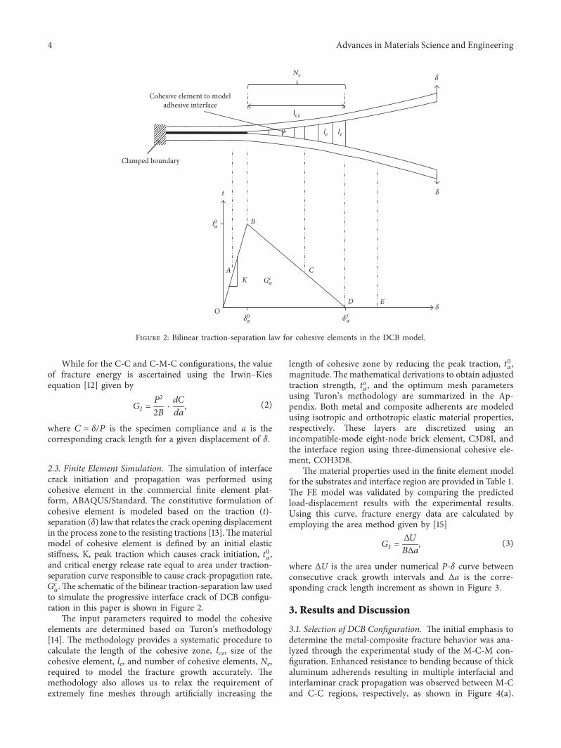
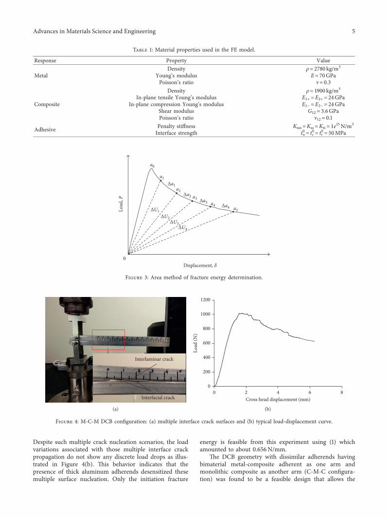
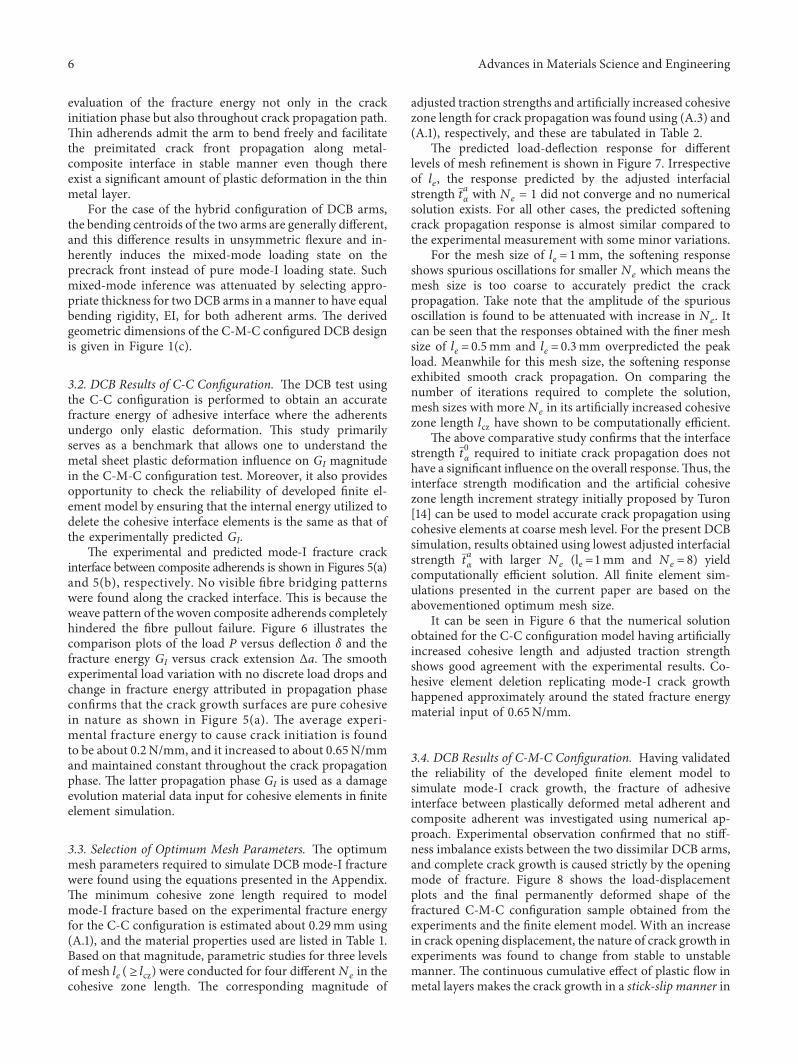
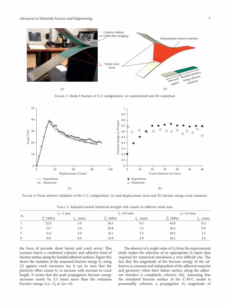
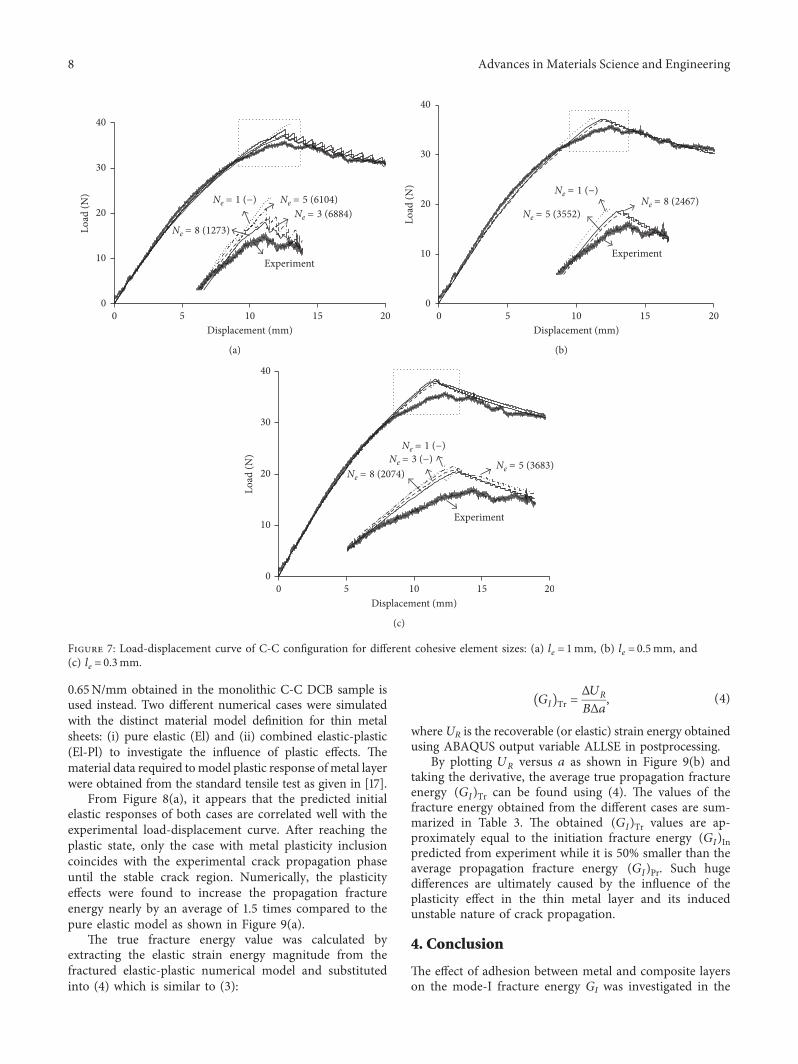
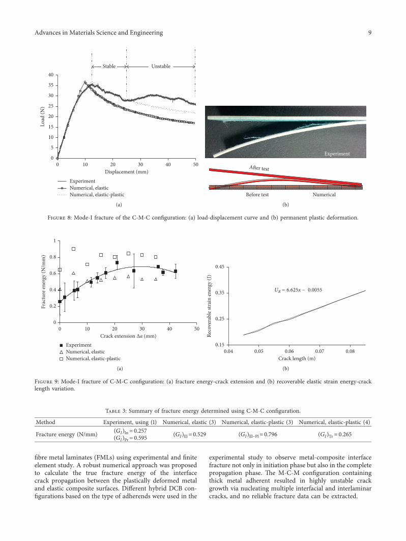
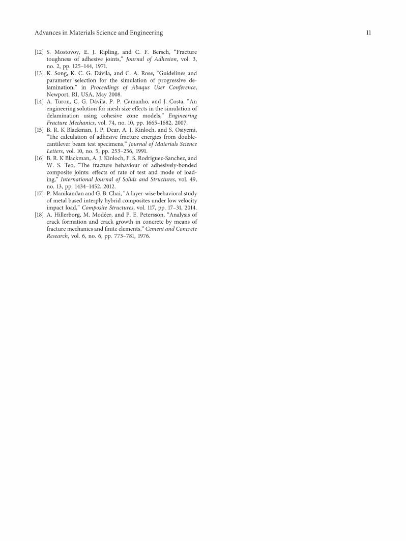