model 15s - incremental shaft encoderencoder.com/literature/datasheet-15s.pdf · 1-800-366-5412 •...
TRANSCRIPT
1-800-366-5412 • www.encoder.com • [email protected] Rev. 04/06/18
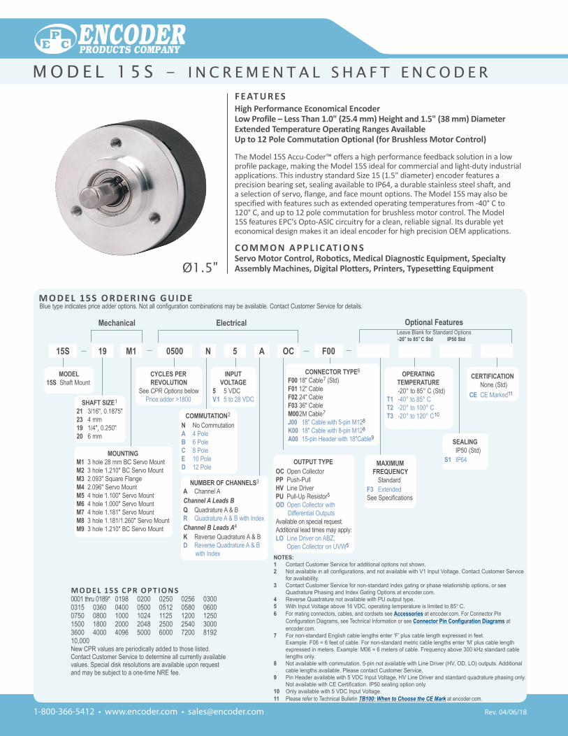
Ø1.5"
F eat u r es High Performance economical encoderLow Profile – Less than 1.0" (25.4 mm) Height and 1.5" (38 mm) Diameterextended temperature Operating ranges availableup to 12 Pole Commutation Optional (for Brushless Motor Control)
The Model 15S Accu-Coder™ offers a high performance feedback solution in a low profile package, making the Model 15S ideal for commercial and light-duty industrial applications. This industry standard Size 15 (1.5" diameter) encoder features a precision bearing set, sealing available to IP64, a durable stainless steel shaft, and a selection of servo, flange, and face mount options. The Model 15S may also be specified with features such as extended operating temperatures from -40° C to 120° C, and up to 12 pole commutation for brushless motor control. The Model 15S features EPC's Opto-ASIC circuitry for a clean, reliable signal. Its durable yet economical design makes it an ideal encoder for high precision OEM applications.
CO M M O n a P P L i C at i O n s Servo Motor Control, Robotics, Medical Diagnostic Equipment, Specialty Assembly Machines, Digital Plotters, Printers, Typesetting Equipment
Mechanical Electrical
NOTES:1 Contact Customer Service for additional options not shown.2 Not available in all configurations, and not available with V1 Input Voltage. Contact Customer Service
for availability.3 Contact Customer Service for non-standard index gating or phase relationship options, or see
Quadrature Phasing and Index Gating Options at encoder.com. 4 Reverse Quadrature not available with PU output type.5 With Input Voltage above 16 VDC, operating temperature is limited to 85° C.6 For mating connectors, cables, and cordsets see Accessories at encoder.com. For Connector Pin
Configuration Diagrams, see Technical Information or see Connector Pin Configuration Diagrams at encoder.com.
7 For non-standard English cable lengths enter ‘F’ plus cable length expressed in feet. Example: F06 = 6 feet of cable. For non-standard metric cable lengths enter ‘M’ plus cable length expressed in meters. Example: M06 = 6 meters of cable. Frequency above 300 kHz standard cable lengths only.
8 Not available with commutation. 5-pin not available with Line Driver (HV, OD, LO) outputs. Additional cable lengths available. Please contact Customer Service.
9 Pin Header available with 5 VDC Input Voltage, HV Line Driver and standard quadrature phasing only. Not available with CE Certification. IP50 sealing option only.
10 Only available with 5 VDC Input Voltage.11 Please refer to Technical Bulletin TB100: When to Choose the CE Mark at encoder.com.
M O D e L 15s O r D e r i n g g u i D eBlue type indicates price adder options. Not all configuration combinations may be available. Contact Customer Service for details.
-20° to 85° C Std IP50 Std
OUTPUT TYPE OC Open CollectorPP Push-PullHV Line DriverPU Pull-Up Resistor5OD Open Collector with
Differential OutputsAvailable on special request.Additional lead times may apply:LO Line Driver on ABZ, Open Collector on UVW5
M O D e L 15s C P r O P t i O n s0001 thru 0189* 0198 0200 0250 0256 0300 0315 0360 0400 0500 0512 0580 0600 0750 0800 1000 1024 1125 1200 1250 1500 1800 2000 2048 2500 2540 3000 3600 4000 4096 5000 6000 7200 8192 10,000New CPR values are periodically added to those listed.Contact Customer Service to determine all currently available values. Special disk resolutions are available upon request and may be subject to a one-time NRE fee.
MAXIMUM FREQUENCY
StandardF3 ExtendedSee Specifications
CONNECTOR TYPE6
F00 18" Cable7 (Std)F01 12" CableF02 24" CableF03 36" CableM00 2M Cable7
J00 18" Cable with 5-pin M128
K00 18" Cable with 8-pin M128
A00 15-pin Header with 18"Cable9
INPUT VOLTAgE
5 5 VDCV1 5 to 28 VDC
COMMUTATION2
N No CommutationA 4 PoleB 6 PoleC 8 PoleE 10 PoleD 12 Pole
CYCLES PER REVOLUTION
See CPR Options belowPrice adder >1800SHAFT SIZE1
21 3/16", 0.1875"23 4 mm19 1/4", 0.250"20 6 mm
NUMBER OF CHANNELS3
A Channel AChannel A Leads BQ Quadrature A & BR Quadrature A & B with Index Channel B Leads A4
K Reverse Quadrature A & BD Reverse Quadrature A & B
with Index
CERTIFICATION None (Std)CE CE Marked11
Optional FeaturesLeave Blank for Standard Options
MODEL15S Shaft Mount
MOUNTINgM1 3 hole 28 mm BC Servo MountM2 3 hole 1.210" BC Servo MountM3 2.093" Square FlangeM4 2.096" Servo MountM5 4 hole 1.100" Servo MountM6 4 hole 1.000" Servo MountM7 4 hole 1.181" Servo MountM8 3 hole 1.181/1.260" Servo MountM9 3 hole 1.210" BC Servo Mount
15S M1 OC19 50500 A F00N
OPERATINg TEMPERATURE
-20° to 85° C (Std)T1 -40° to 85° CT2 -20° to 100° CT3 -20° to 120° C10
SEALINg IP50 (Std)S1 IP64
M o d e l 1 5 s - i n c r e M e n t a l s h a f t e n c o d e r
1-800-366-5412 • www.encoder.com • [email protected]
0.040 [1.02]
0.547 +0.000-0.001
[ 13.89 +0.00-0.03 ]
0.079 [2.01]
0.062 [1.57]0.055 [1.40]0.93 [23.6]
1.375 +0.000-0.001
[ 34.92 +0.00-0.03 ]
Ø1.625 [Ø41.28]
4-40 UNC-2B 0.25 [6.35] DEEP3X 120° Ø1.210 [30.73] B.C.
1.5 [38]
Ø0.2498 +0.0000-0.0004
[ 6.34 +0.00-0.01 ]
0.60 [15.2]CABLE LENGTH18" [457] STANDARD
15-serv2
PTOLERANCEISSUE DATE ENCODER PRODUCTS COMPANY
electricalInput Voltage ............5 VDC +10% Fixed Voltage
4.75 to 28 VDC max for temperatures up to 85° C 4.75 to 24 VDC for temperatures between 85° to 100° C
Input Current .................140 mA max (65 mA typical for most configurations) with no output load
Output Format ......... Incremental – Two square waves in quadrature with channel A leading B for clockwise shaft rotation, as viewed from the encoder mounting face. See Waveform Diagrams.
Output Types............Open Collector – 20 mA max per channel Push-Pull – 20 mA max per channel Pull-Up – Open Collector with 2.2K ohm internal resistor, 20 mA max per channel Line Driver – 20 mA max per channel (Meets RS 422 at 5 VDC supply.)
Index .........................Once per revolution. 1 to 189 CPR: Ungated 190 to 10,000 CPR: Gated to output A See Waveform Diagrams.
Max. Frequency .......Standard Frequency Response is 200 kHz for CPR 1 to 2540 500 kHz for CPR 2541 to 5000 1 MHz for CPR 5001 to 10,000 Extended Frequency Response (optional) is 300 kHz for CPR 2000, 2048, 2500, and 2540.
Electrical Protection ..Reverse voltage and output short circuit protected. NOTE: Sustained reverse voltage may result in permanent damage.
Noise Immunity ......... Tested to BS EN61000-6-2; BS EN50081-2; BS EN61000-4-2; BS EN61000-4-3; BS EN61000-4-6; BS EN500811
Quadrature ...............67.5° electrical or better is typical, Edge Separation 54° electrical minimum at temperatures > 99° C
Waveform Symmetry ..180° (±18°) electrical (single channel encoder)Accuracy ...................Within 0.017° mechanical or 1 arc-minute
from true position (for CPR >189).Commutation ...........Up to 12 pole. Contact Customer Service for
availability.Comm. Accuracy ......1° mechanical
MechanicalMax Shaft Speed ......8000 RPM. Higher speeds may be
achievable, contact Customer Service.Shaft Material .........Stainless SteelRadial Shaft Load ....5 lb max. Rated load of 2 to 3 lb for bearing
life of 1.2 x 10¹⁰ revolutionsAxial Shaft Load .......5 lb max. Rated load of 2 to 3 lb for bearing
life of 1.2 x 10¹⁰ revolutionsStarting Torque ........ IP50- 0.05 oz-in
IP64- 0.4 oz-inMoment of Inertia ...6.7 x 10-5 oz-in-sec2 (4.8 gm-cm2)Weight ......................3 oz typical
environmentalStorage Temp ........... -25° to 85° C Humidity...................98% RH non-condensing Vibration...................10 g @ 58 to 500 Hz Shock ........................80 g @ 11 ms durationSealing ...................... IP50 standard; IP64 available
M O D e L 15s s P eC i F i C at i O n s
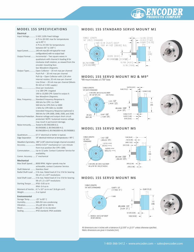
M O D e L 15s s e rvO M O u n t M2 & M9*
M O D e L 15s s e rvO M O u n t M5
M O D e L 15s s e rvO M O u n t M6
*M9 mount includes a 0.750" boss
All dimensions are in inches with a tolerance of +0.005" or +0.01" unless otherwise specified.Metric dimensions are given in brackets [mm].
4-40 UNC-2B .300 [7.62] DEEP4X @ 90° Ø1.100 [27.94] B.C.
.50 [12.8]
1.5 [38]
1.04 [26.4]
.040 [1.02]
.132 [3.36]
.093 [2.36]
.078 [1.98]15-serv5
CABLE LENGTH18" [457] STANDARD
1.3115 ±0.0005
[33.312 ±0.013]
0.8745 ±0.0005
[Ø22.212 ±0.013]
1.437 +0.000-0.005
[ Ø36.50 +0.00-0.13 ]
Ø0.2498 +0.0000-0.0004
[ Ø6.345 +0.000-0.010 ]
PTOLERANCEISSUE DATE ENCODER PRODUCTS COMPANY
M O D e L 15s sta n Da r D s e rvO M O u n t M1
0.120 [3.04]
1.5 [38]
0.60 [15.2]
Ø0.2498 +0.0000-0.0004
[ 6.34 +0.00-0.01 ]
CABLE LENGTH18" [457] STANDARD
15-serv6
M3X0.5 -6H 0.187 DEEP4X Ø1.000 B.C.
0.6875 +0.000-0.001
[ 17.462 +0.00-0.03 ]
1.500
0.82 [20.8]
1-800-366-5412 • www.encoder.com • [email protected]
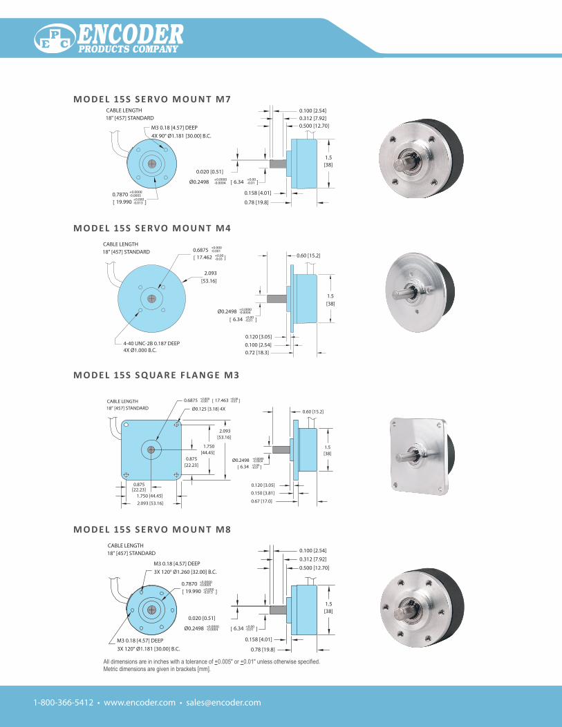
M O D e L 15s s e rvO M O u n t M4
M O D e L 15s s q ua r e F L a n g e M3
M O D e L 15s s e rvO M O u n t M7
M O D e L 15s s e rvO M O u n t M8
All dimensions are in inches with a tolerance of +0.005" or +0.01" unless otherwise specified.Metric dimensions are given in brackets [mm].
Ø0.2498 +0.0000-0.0004 [ 6.34 +0.00
-0.01 ]
0.500 [12.70]
0.158 [4.01]
0.78 [19.8]
CABLE LENGTH18" [457] STANDARD
15-SERV7
1.5 [38]
0.7870 +0.0000-0.0005
[ 19.990 +0.000-0.013 ]
M3 0.18 [4.57] DEEP4X 90° Ø1.181 [30.00] B.C.
0.100 [2.54]0.312 [7.92]
0.020 [0.51]
PTOLERANCEISSUE DATE ENCODER PRODUCTS COMPANY
Ø0.2498 +0.0000-0.0004 [ 6.34 +0.00
-0.01 ]
0.500 [12.70]
0.158 [4.01]
0.78 [19.8]
CABLE LENGTH18" [457] STANDARD
15-SERV8
1.5 [38]
0.7870 +0.0000-0.0005
[ 19.990 +0.000-0.013 ]
M3 0.18 [4.57] DEEP3X 120° Ø1.260 [32.00] B.C.
0.100 [2.54]
0.312 [7.92]
0.020 [0.51]
M3 0.18 [4.57] DEEP3X 120° Ø1.181 [30.00] B.C.
DATE NAME AND TITLE
EP
INITIALDECIMAL
TOLERANCENEXT ASSEMBLY
ISSUE DATEC ENCODER PRODUCTS COMPANY
PTOLERANCEISSUE DATE ENCODER PRODUCTS COMPANY
0.72 [18.3]0.100 [2.54]
1.5 [38]
0.60 [15.2]
0.120 [3.05]
Ø0.2498 +0.0000-0.0004
[ 6.34 +0.00-0.01 ]
CABLE LENGTH18" [457] STANDARD
15-serv4
4-40 UNC-2B 0.187 DEEP4X Ø1.000 B.C.
2.093 [53.16]
0.6875 +0.000-0.001
[ 17.462 +0.00-0.03 ]
Ø0.125 [3.18] 4X
0.6875 +0.000-0.001 [ 17.463 +0.00
-0.03 ]
1.5 [38]
0.875 [22.23]
0.875 [22.23]
0.60 [15.2]
0.120 [3.05]
0.150 [3.81]
0.67 [17.0]
1.750 [44.45]
2.093 [53.16]
1.750 [44.45]2.093 [53.16]
Ø0.2498 +0.0000-0.0004
[ 6.34 +0.00-0.01 ]
CABLE LENGTH18" [457] STANDARD
15-serv3
PTOLERANCEISSUE DATE ENCODER PRODUCTS COMPANY
1-800-366-5412 • www.encoder.com • [email protected]
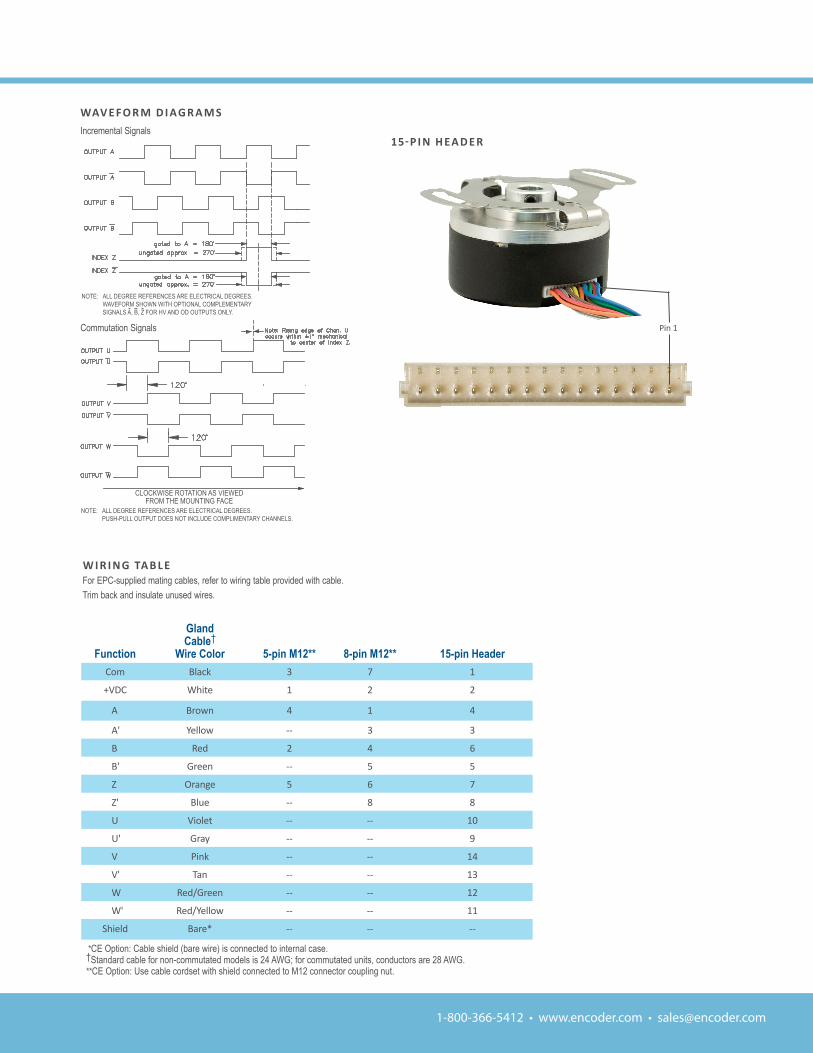
15-P i n H EA D E R
Pin 1
Function
glandCable†
Wire Color 5-pin M12** 8-pin M12** 15-pin HeaderCom Black 3 7 1
+VDC White 1 2 2
A Brown 4 1 4
A' Yellow -- 3 3
B Red 2 4 6
B' Green -- 5 5
Z Orange 5 6 7
Z' Blue -- 8 8
U Violet -- -- 10
U' Gray -- -- 9
V Pink -- -- 14
V' Tan -- -- 13
W Red/Green -- -- 12
W' Red/Yellow -- -- 11
Shield Bare* -- -- --
*CE Option: Cable shield (bare wire) is connected to internal case.†Standard cable for non-commutated models is 24 AWG; for commutated units, conductors are 28 AWG.**CE Option: Use cable cordset with shield connected to M12 connector coupling nut.
Commutation Signals
NOTE: ALL DEGREE REFERENCES ARE ELECTRICAL DEGREES. PUSH-PULL OUTPUT DOES NOT INCLUDE COMPLIMENTARY CHANNELS.
Wav e FO r M D i ag r a M sIncremental Signals
NOTE: ALL DEGREE REFERENCES ARE ELECTRICAL DEGREES. WAVEFORM SHOWN WITH OPTIONAL COMPLEMENTARY SIGNALS A, B, Z FOR HV AND OD OUTPUTS ONLY.
W i r i n g ta B L eFor EPC-supplied mating cables, refer to wiring table provided with cable.Trim back and insulate unused wires.
CLOCKWISE ROTATION AS VIEWED FROM THE MOUNTING FACE