model 3440 surface moisture-density gauge · (shallow depth) and astm d-3017: standard test method...
TRANSCRIPT

Manual of Operation and Instruction
TTrrooxxlleerr RRooaaddRReeaaddeerr™™ MMooddeell 33444400 SSuurrffaaccee
MMooiissttuurree--DDeennssiittyy GGaauuggee
Troxler Electronic Laboratories, Inc.
3008 Cornwallis Rd. x P.O. Box 12057 Research Triangle Park, NC 27709
Phone: 1.877.TROXLER Outside the USA: +1.919.549.8661
Fax: +1.919.549.0761 www.troxlerlabs.com

viii
TABLE OF CONTENTS
CHAPTER 1: INTRODUCTION ................................... 1–1
Introduction .............................................................................................. 1–2
Gauge Parts and Accessories .............................................................. 1–5
Unpacking and Inspection .................................................................... 1–7
CHAPTER 2: THEORY OF OPERATION .................. 2–1 Density........................................................................................................ 2–2
Moisture ..................................................................................................... 2–5
Calibration ................................................................................................. 2–7
CHAPTER 3: GAUGE SETUP ...................................... 3–1
Gauge Illustration .................................................................................... 3–2
Control Panel............................................................................................ 3–3
Source Rod Positions ............................................................................. 3–5
Daily Inspection ....................................................................................... 3–6
Turning the Gauge On .......................................................................... 3–6
Gauge Setup ............................................................................................. 3–8
CHAPTER 4: USING THE GAUGE ............................ 4–15
Taking the Standard Count ................................................................ 4–16
Site Preparation ..................................................................................... 4–22
Taking Measurements.......................................................................... 4–25
Recall ........................................................................................................ 4–31
CHAPTER 5: SETUP MENU ....................................... 5–1
Setup Menu .............................................................................................. 5–2
Stat Test ..................................................................................................... 5–3
Model 3440 ix
Drift Test .................................................................................................... 5–6
Nomograph .............................................................................................. 5–9
Precision .................................................................................................. 5–14
Options .................................................................................................... 5–16
Percent Air Voids (Soil Mode) ........................................................... 5–18
CHAPTER 6: TARGET MENU ..................................... 6–1
Target Menu ............................................................................................. 6–2
Target Values ........................................................................................... 6–3
CHAPTER 7: CALIBRATION OFFSETS ........................ 7–1
About Offsets ........................................................................................... 7–2
Density Offset ........................................................................................... 7–4
Moisture Offset ........................................................................................ 7–5
Trench Offset ............................................................................................ 7–9
CHAPTER 8: PROJECT DATA .................................... 8–1
Project Menu ............................................................................................ 8–2
Select a Project ........................................................................................ 8–3
View Project Data .................................................................................... 8–4
Create a Project ....................................................................................... 8–5
Erase Projects ........................................................................................... 8–6
Output Project ......................................................................................... 8–7
Set Output Destination ........................................................................ 8–11
Deactivate a Project.............................................................................. 8–11
Auto-Store .............................................................................................. 8–12
Manual Store .......................................................................................... 8–14
CHAPTER 9: EXTENDED MENU ................................ 9–1

x
Extended Menu ....................................................................................... 9–2
Clock/Calendar ........................................................................................ 9–3
User ID ........................................................................................................ 9–3
Customer Name ...................................................................................... 9–3
Language................................................................................................... 9–4
Source Decay ........................................................................................... 9–4
Erase Standard Counts .......................................................................... 9–5
Low Battery Warning .............................................................................. 9–6
Software Reset ......................................................................................... 9–7
Test Menu ................................................................................................. 9–7
APPENDIX A : MAINTENANCE & TROUBLESHOOTING .. A-1
Troubleshooting ...................................................................................... A-2
Display Contrast .................................................................................... A-10
Batteries ................................................................................................... A-11
Battery Charging ................................................................................... A-13
Mechanical Maintenance .................................................................... A-16
Replacement Parts ................................................................................ A-20
Returning the Gauge for Service ...................................................... A-22
APPENDIX B : SPECIFICATIONS ...................................... B-1
Measurement Specifications ................................................................. B-2
Radiological Specifications .................................................................... B-4
Electrical Specifications ........................................................................... B-4
Mechanical Specifications ...................................................................... B-6
APPENDIX C : TRANSPORTING & SHIPPING .................. C-1
U.S. Shipping Requirements ................................................................. C-2

Model 3440 xi
Canadian Shipping Requirements ...................................................... C-4
APPENDIX D : RADIATION THEORY & SAFETY ............... D-1
Radiation Theory ..................................................................................... D-2
Radiation Safety ....................................................................................... D-5
Regulatory Requirements ...................................................................D-13
Gauge Use Precautions .......................................................................D-16
Radiation Profile ....................................................................................D-17
APPENDIX E : UNIT CONVERSION .................................. E-1
Measurement Units ................................................................................. E-2
Radiological Units ..................................................................................... E-2
APPENDIX F : STANDARD COUNT LOG .......................... F-1
APPENDIX G : SPECIAL EUROPEAN CONSIDERATIONS . G-1
Declaration of Conformity .................................................................... G-2
Safety Warnings ....................................................................................... G-3
APPENDIX H : GLOBAL POSITIONING SYSTEM (GPS) ..... H-1
GPS Accuracy ........................................................................................... H-2
INDEX
WARRANTY

xii
LIST OF FIGURES
Figure 1. Model 3440 Gauge and Accessories ............................... 1–6
Figure 2. Direct Transmission Geometry .......................................... 2–3
Figure 3. Backscatter Geometry .......................................................... 2–3
Figure 4. Backscatter Surface Density Effects .................................. 2–4
Figure 5. Effect of Moisture on Depth of Measurement .............. 2–6
Figure 6. Gauge Illustration .................................................................. 3–2
Figure 7. Model 3440 Keypad ............................................................. 3–3
Figure 8. Source Rod Positions ........................................................... 3–5
Figure 9. Standard Count Position ................................................... 4–18
Figure 10. Drill Rod Positioning ......................................................... 4–23
Figure 11. Marking the Test Area ..................................................... 4–24
Figure 12. Adjusting the Display Contrast ...................................... A-10
Figure 13. NiMH Battery Pack and AA Batteries .......................... A-12
Figure 14. Diagram of an Atom .......................................................... D-2
Figure 15. Effect of Distance on Exposure ....................................... D-6
Figure 16. Cleaning the Tungsten Sliding Block .......................... D-11
Figure 17. Model 3440 Gauge and Transport Case ................... D-17

Model 3440 xiii
LIST OF TABLES
Table 1. Model 3440 Keypad Functions ........................................... 3–4
Table 2. Spreadsheet Column Definitions ...................................... 8–10
Table 3. Error Messages ........................................................................ A-7
Table 4. Typical Battery Operating Life ........................................... A-12
Table 5. Radiation Profile for Model 3440 Gauge ...................... D-18
Table 6. GPS Position Accuracy .......................................................... H-4

xiv
ATTENTION MODEL 3440 GAUGE OWNER
This unit contains functions that require an Access Code to be entered. This allows some control over the access to these functions. If you would like management to
retain this control, remove this page upon receipt of the gauge and file it somewhere safe.
THE ACCESS CODE IS FOR THIS GAUGE IS:
4708

Model 3440 1–1
CChhaapptteerr 11:: IInnttrroodduuccttiioonn
This chapter covers the following topics and tasks:
9 An introduction to your new Model 3440 gauge 9 Inspecting and unpacking 9 Included parts and accessories

1–2
IInnttrroodduuccttiioonn The Model 3440 Surface Moisture-Density Gauges have become the industry standard for measuring the moisture content and density of construction materials. With the new Model 3440 gauge, Troxler has added a number of features to the proven technology of the company’s earlier products to provide increased performance, flexibility, ease of use, and operator safety. Using the Model 3440 gauge, you can quickly and precisely measure the moisture content and density of construction materials. The gauge features: i Two measurement modes (Soil and Asphalt) for precise
compaction control readings in most construction materials: Use Soil Mode for moisture/density determinations in soil and soil-stone materials in layers of four inches or greater. Use Asphalt Mode for density determinations in asphalt or hardened concrete layers of four inches or greater.
i A Nomograph function for density determinations in asphalt layers of fewer than four inches.
i Calibration offsets (density, moisture, and trench) to expand measurement possibilities, and to enhance gauge readings on materials that may fall outside the range of factory calibration.
i Over 30 functions to facilitate all phases of testing compaction on construction materials.
i A backlit LCD screen to help you read the display during night construction.
i Easy-to-use keypad and user-friendly menus to reduce training time to increase productivity. A backlit keypad is available as an upgrade (see page 5–17 for more information).
i An internally mounted beeper, which emits a short tone in response to a valid keystroke on the keypad. The beeper sounds a longer tone if you press an invalid key, if the gauge

Model 3440 1–3
displays an error message, or to signal the conclusion of a measurement.
i A USB port that can be used to output data to a USB printer or flash drive. A list of compatible USB devices is available at: www.troxlerlabs.com/documents
i A serial port used to connect the gauge to a computer or printer for data transfer and printing.
i An optional remote keypad, including a ¢START² and ¢ESC² key, at the top of its source rod housing. See page 5–16 for more information.
i In addition to the internal beeper, a louder external beeper is available (see page 5–16). The external beeper performs the same functions as the internal one, and can be enabled or disabled as required.
The Model 3440 can also be equipped with an optional global
positioning system (GPS) receiver. The GPS receiver enables the gauge to store precise GPS coordinates, along with the standard date and time stamp, for each measurement. For more information on the GPS option, refer to page 5–17.
ASTM Standards The Model 3440 gauges meet or exceed all applicable American Society of Testing and Materials (ASTM) standards (or corresponding equivalent), including: i ASTM D-2950: Standard Test Method for Density of
Bituminous Concrete in Place by Nuclear Method. i ASTM D-6938: Standard Test Methods for In-Place Density
and Water Content of Soil and Soil-Aggregate by Nuclear Methods (Shallow Depth)

1–4
NOTE
As of November 2006, ASTM D-6938 replaces ASTM D-2922: Standard Test Methods for Density of Soil and Soil-Aggregate in Place by Nuclear Methods (Shallow Depth) and ASTM D-3017: Standard Test Method for Water Content of Soil and Rock in Place by Nuclear Methods (Shallow Depth).
Any licensing issues discussed in this manual are for the United States. To purchase a Model 3440 in Canada, owners must obtain a radioisotope license from the Canadian Nuclear Safety Commission (CNSC). The owner should obtain copies of the CNSC Regulations and the Transportation of Dangerous Goods
Act and Regulations (TDG). For other countries, please consult your local regulatory agency. Owners are encouraged to require study of this manual before allowing anyone to use the gauge. A potential hazard does exist if improperly used. Appendix C and Appendix D, which cover radiological safety and transportation requirements, should be required reading for all users and potential users. If these appendices are not completely understood, users should seek assistance from Troxler, an appointed Troxler representative, or others designated within the user's organization. Additional radiation safety information is available by completing a Troxler Nuclear Gauge Safety Training Course. For pricing and availability of these in-person and online courses, visit the Troxler website at www.troxlerlabs.com/training or contact your Troxler representative. Before operating the gauge, users in European countries must refer to : Special European Considerations for special considerations, additional safety warnings, and the Declaration of Conformity. Because changes are made to local, state, and federal regulations on a continuing basis, the owner/operator must maintain awareness of current requirements. The responsibility
for compliance ultimately falls on the owner. An owner in the United States may also wish to purchase and subscribe to Titles

Model 3440 1–5
10 and 49 of the Code of Federal Regulations (CFR) in addition to applicable local/state regulations.
GGaauuggee PPaarrttss aanndd AAcccceessssoorriieess Use Figure 1 and the list below to identify the gauge and parts as they are unpacked. i The gauge is the portable instrument containing all
electronic modules, the rechargeable battery pack, detectors, and the radioactive sources.
i The Reference Standard Block provides a measurement standard for standard counts and is used during stat and drift tests.
i The Drill Rod is used to drill holes for direct transmission measurements. Do not use the source rod of the gauge to drill holes.
i The Scraper Plate / Drill Rod Guide is used to prepare the test site and to guide the drill rod when preparing the site for direct transmission measurements.
i The Extraction Tool provides leverage to remove the drill rod from soil materials.
i The AC charger and DC adapter are used to charge the gauge batteries. The AC charger accepts 90 – 220 V AC, 50/60 Hz and supplies 12 V DC. The DC adapter allows recharging from an automobile accessory power outlet.
i The Transport Case provided with the gauge has been approved as a Type A package and should not be altered. Always use this transport case when transporting or shipping the gauge.
i The Manual of Operation and Instruction details how to use the gauge.

1–6
Figure 1. Model 3440 Gauge and Accessories

Model 3440 1–7
UUnnppaacckkiinngg aanndd IInnssppeeccttiioonn Troxler recommends that all operators wear a dosimeter while working with the gauge. Upon receipt of the gauge from the factory, perform a complete inspection and inventory. If the shipping case and/or any other part or accessory appears damaged, notify the carrier and your Troxler Representative immediately. Save the box and any packing material for shipping to another location or back to the factory Check the shipping case for the following: i Gauge i Reference Standard Block i Drill Rod i Scraper Plate/Drill Rod Guide i Extraction Tool i AC charger i DC adapter (for a vehicle cigarette lighter) i Manual of Operation and Instruction
i Gauge warranty i Source Certificate i Transportation Guide (This guide refers to U.S. standards. All
other countries please refer to local regulations. In the absence of local regulations, please use this guide as a reference only.)
NOTE
Charge the batteries for three hours prior to initial use.

1–8
Complete the unpacking and inspection by following these steps: 11.. Lift the gauge from the transport case and inspect the
outside surface for damage. 22.. Check the lock on the source rod handle and make sure the
keys fit. 33.. Remove the lock, release the trigger, and check the source
rod operation. It should move up and down with minimal effort.
44.. Replace the handle lock and return the gauge to the transport case.
NOTES

Model 3440 2–1
CChhaapptteerr 22:: TThheeoorryy ooff OOppeerraattiioonn
This chapter covers the following topics and tasks:
9 Theory of operation 9 Direct transmission and backscatter modes 9 Overview of density and moisture measurements 9 Explanation of the sources and detector geometry

2–2
DDeennssiittyy The Model 3440 gauge utilizes two modes of operation: direct
transmission mode (with the source rod extended into the material) and backscatter mode. Figure 2 and Figure 3 illustrate these two modes of operation.
WARNING!
The source rod should always be locked in the SAFE position when the gauge is not in use.
Source rod positions are described on page 3–5. In direct transmission mode, the rod containing the Cesium-137 (8 mCi/0.3 GBq) source is lowered to the desired depth. The detectors in the gauge base measure the radiation emitted by the source rod. Gamma photons reaching the detectors must first pass through the material, colliding with electrons present in the material. Generally, the lower the number of photons that reach the detectors, the more dense the material is. In backscatter mode, the gamma photons that enter the material must be scattered (or reflected) to reach the detectors. With the rod locked in the first notch, the source and detectors are in the same plane, referred to as the backscatter position. Photons emitted from the source penetrate the material and the detectors measure the scattered photons. While the direct transmission geometry measures the average density of the material from the source to the surface, the backscatter geometry yields an average heavily weighted by the density close to the surface. Figure 4 shows two normalized top layer effect curves, illustrating the percentages of photons at the detectors for various depths. The two curves can be used to compute the gauge response to layered material of different densities. For example, the density of the top inch of a surface layer accounts for about 52% of the backscatter density measurement.

Model 3440 2–3
Figure 2. Direct Transmission Geometry
Figure 3. Backscatter Geometry

2–4
Figure 4. Backscatter Surface Density Effects
(Top Layer Effect Curves)
Model 3440 2–5
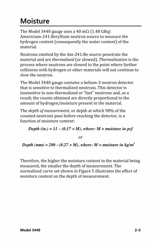
MMooiissttuurree The Model 3440 gauge uses a 40 mCi (1.48 GBq) Americium-241:Beryllium neutron source to measure the hydrogen content (consequently the water content) of the material. Neutrons emitted by the Am-241:Be source penetrate the material and are thermalized (or slowed). Thermalization is the process where neutrons are slowed to the point where further collisions with hydrogen or other materials will not continue to slow the neutron. The Model 3440 gauge contains a helium-3 neutron detector that is sensitive to thermalized neutrons. This detector is insensitive to non-thermalized or “fast” neutrons and, as a result, the counts obtained are directly proportional to the amount of hydrogen/moisture present in the material. The depth of measurement, or depth at which 98% of the counted neutrons pass before reaching the detector, is a function of moisture content:
Depth (in.) = 11 – (0.17 u M), where: M = moisture in pcf
or Depth (mm) = 280 - (0.27 u M), where: M = moisture in kg/m3
Therefore, the higher the moisture content in the material being measured, the smaller the depth of measurement. The normalized curve set shown in Figure 5 illustrates the effect of moisture content on the depth of measurement.

2–6
Figure 5. Effect of Moisture on Depth of Measurement
Model 3440 2–7
CCaalliibbrraattiioonn Troxler calibrates the gauge at the factory and recommends that it always be calibrated by an authorized Troxler service center. For a list of Troxler and authorized Troxler service centers, refer to page ii of this manual or visit the Troxler website at: www.troxlerlabs.com/services
Offsets The factory calibration provides accurate results for the majority of materials encountered in construction. If the gauge is to be used to test materials not covered by the factory calibration, the readings can be adjusted using an offset. Perform a density offset if the test material is outside the density range for average soil or if the material composition varies from average soil/asphalt. Perform a moisture offset if the test material contains hydrogenous materials (other than water) or materials that absorb neutrons. Materials such as cement, gypsum, coal, mica, and lime all contain chemically bound hydrogen that will cause the gauge to display a moisture content that is higher than it actual. Material such as boron and cadmium are neutron absorbers and will cause the gauge to display a moisture count that is lower than actual. Vertical structures scatter neutrons and gamma photons back to the gauge. This could result in inaccurate moisture and density readings. To take readings in a trench or within 0.6 m (2 ft.) of a large vertical structure, perform a trench offset.

Model 3440 3–1
CChhaapptteerr 33:: GGaauuggee SSeettuupp
This chapter covers the following topics and tasks:
9 Overview of the control panel 9 Source rod positions 9 Daily inspection 9 Turning the gauge on 9 Using the Setup menu
3–2
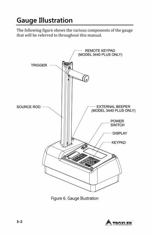
GGaauuggee IIlllluussttrraattiioonn The following figure shows the various components of the gauge that will be referred to throughout this manual.
Figure 6. Gauge Illustration

Model 3440 3–3
CCoonnttrrooll PPaanneell The gauge’s control panel contains the keypad, power switch, display, and USB port, battery charging indicator, charger connector, and the RS-232 port. The gauge is equipped with an internal beeper to verify keystrokes. If a beep is not heard when a key is pressed, the keystroke was not recognized and should be repeated. Table 1 on page 3–4 provides a description of each key.
NOTE
The gauge will automatically turn off after five hours if no keys are pressed.
���������5LHK`������������������$ 03�Q��752?/(5���3�L� � ��6 7$ 57!
POWER SWITCH
BATTERYCHARGINGINDICATOR
CHARGERCONNECTOR
RS-232 PORT
USB PORT*
Figure 7. Model 3440 Keypad

3–4
Table 1. Model 3440 Keypad Functions
KEY FUNCTION
¢STORE² Store the most recent data in the current project file.
¢RECALL² Display the most recent data.
¢PROJ² Select or create a project file and view, output, or erase project data file.
¢STATUS² Display gauge status information.
¢SETUP² Display the gauge Setup menu.
¢OFFSET² Enable, disable, or change a density, moisture, or trench offset.
¢TARGET² Select, enter, or disable a Gmb (Marshall), Proctor, or Gmm (Voidless density) value.
¢MODE² Select Asphalt or Soil measurement mode.
¢STD² Take a standard count.
¢SPACE² Enter a space.
¢LIGHT² Manually toggle the LCD and keypad backlights on and off.
¢YES² Respond yes to yes/no questions.
¢NO² Respond no to yes/no questions.
¢ESC² Return the display to the Ready screen without storing or updating the data.
¢0² .. ¢9² Enter numbers and access menu options.
¢BACK SPACE² Moves cursor back one space.
¢n², ¢p² Scroll through menu options or view screens.
¢ . ² Enter a decimal point.
¢ALPHA LOCK² Access the letters.
¢A² .. ¢Z² Enter letters. Access these keys by first pressing ¢ALPHA LOCK².
¢ENTER/START² Accept data entry or begin a measurement.

Model 3440 3–5
SSoouurrccee RRoodd PPoossiittiioonnss As shown in Figure 8, the source rod can be placed in the SAFE, backscatter, or direct transmission positions. When not taking measurements, keep the source rod in the SAFE position. When measuring thin layer or other materials through which you cannot drill a hole, use the backscatter position. In the direct transmission positions, the source rod extends into a pre-drilled hole.
BS
2"50mm
3"75mm
4"100mm
5"125mm
6"150mm
7"175mm
8"200mm
9"225mm
10"250mm
11"275mm
12"300mm
Figure 8. Source Rod Positions
(Maximum Depth of 300 mm in Increments of 50 mm)

3–6
DDaaiillyy IInnssppeeccttiioonn The gauge should be inspected daily before use to ensure proper operation of all safety features. Refer to page D-9 for the inspection procedure.
TTuurrnniinngg tthhee GGaauuggee OOnn The gauge uses rechargeable NiMH batteries (included) as a power source. When first turned on, the control panel displays test characters before proceeding to the self-test. To turn the gauge on, toggle the on/off switch located to the left of the gauge’s display. Upon turning the gauge on, the gauge displays:
-Model 3440-
Vx.xx SN: xxx
The gauge then performs a test of its LCD (liquid crystal display):
Testing LCD 123456789ABCDEF
After the gauge performs a 300-second self-test, the gauge enters the Ready mode. In this state any of the gauge functions may be accessed. The Ready mode display is:
-READY- g 01-08-2014 12:21 PM
Prj: TROXLER Press <START>

Model 3440 3–7
NOTE
The symbol g in the upper right of the display indicates that the GPS option (see page 5–17) is installed, the option is enabled, and the gauge is receiving GPS satellite signals.
NOTE
If the gauge display is difficult to read in bright light, adjust the contrast as described in the Display Contrast section on page A-10.
After five hours of no activity, the gauge automatically performs a total power shutdown.
NOTE
If the charge calibration (see page A-14) is BAD, the gauge will not perform an automatic shutdown.
3–8
GGaauuggee SSeettuupp After turning the gauge on, you can set several parameters, including measurement units and count time. These parameters do not usually change once they are set. The gauge offers a Status function that enables you to view selected information about the current gauge status and setup. To access this function, press the ¢STATUS² key. The gauge displays two screens of information, including the measurement units, count time, measurement mode, battery status, Gmb (Marshall) value, Proctor value, Gmm (Voidless density) value, and measurement depth. Use the arrow keys to scroll between the two screens. To begin, press the ¢SETUP² key. For information on all of the functions available from the Setup menu, see Chapter 5: Setup Menu.
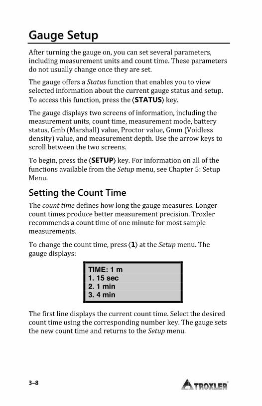
Setting the Count Time The count time defines how long the gauge measures. Longer count times produce better measurement precision. Troxler recommends a count time of one minute for most sample measurements. To change the count time, press ¢1² at the Setup menu. The gauge displays:
TIME: 1 m 1. 15 sec 2. 1 min 3. 4 min
The first line displays the current count time. Select the desired count time using the corresponding number key. The gauge sets the new count time and returns to the Setup menu.

Model 3440 3–9
Setting Measurement Units The gauge can display measurement results in either U.S. units (pcf) or metric (SI) units (kg/m3 or g/cm3). To select the units, press ¢2² at the Setup menu. The gauge displays:
- UNITS – 1. pcf 2. kg/m3 3. g/cm3
Select the new units using the corresponding number key. The gauge sets the new units and returns to the Setup menu.
Setting the Depth The Model 3440 gauge offers two depth modes: Automatic and Manual. In the Automatic mode, the gauge software determines the source rod depth automatically. In the Manual mode, the operator must enter the source rod depth at a gauge prompt whenever taking a measurement. The Depth Mode function allows you to set the depth mode. To access this function, press ¢2² at the Setup menu .The gauge displays:
Mode: Manual 1. Manual 2. Auto
Press # to Select
Select the desired depth mode using the corresponding number key. After the depth mode is selected, the gauge sets the mode and returns to the Setup menu.

3–10
Extended Menu The gauge is shipped with the current date and time (Eastern Standard Time) stored in its memory. In addition, the gauge can store a user ID and customer name. These settings are accessed from the Extended menu. This menu includes functions that are intended for use by authorized personnel only, and requires the use of the access
code shown at the front of this book. To access the Extended menu, press ¢.² ¢9² at the Setup menu. The gauge requests an access code:
Input Access Code _
Press <ENTER>
After entering the access code (see page xiv), the gauge displays the Extended menu. After setting the date and time, user ID, and/or customer name as described in the following sections, press ¢ESC² to return to the Setup menu. For information on all of the functions available from the Extended menu, refer to Chapter 9: Extended Menu. Clock/Calendar The Clock/Calendar function allows the operator to change the date and time, and to select the display format for each. To access the Clock/Calendar menu, press ¢1² at the Extended menu. The gauge displays:
- Clock/Calendar ↨ 1. Change Time 2. Change Date 3. Time Format
Model 3440 3–11
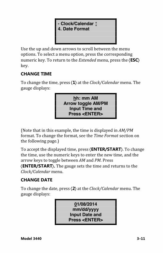
- Clock/Calendar ↨ 4. Date Format
Use the up and down arrows to scroll between the menu options. To select a menu option, press the corresponding numeric key. To return to the Extended menu, press the ¢ESC² key. CHANGE TIME
To change the time, press ¢1² at the Clock/Calendar menu. The gauge displays:
hh: mm AM Arrow toggle AM/PM
Input Time and Press <ENTER>
(Note that in this example, the time is displayed in AM/PM
format. To change the format, see the Time Format section on the following page.) To accept the displayed time, press ¢ENTER/START². To change the time, use the numeric keys to enter the new time, and the arrow keys to toggle between AM and PM. Press ¢ENTER/START². The gauge sets the time and returns to the Clock/Calendar menu. CHANGE DATE
To change the date, press ¢2² at the Clock/Calendar menu. The gauge displays:
01/08/2014 mm/dd/yyyy
Input Date and Press <ENTER>

3–12
(Note that in this example, the time is displayed in mm/dd/yyyy
format. To change the date format, refer to the Date Format section below.) To accept the displayed date, press ¢ENTER/START². To change the date, use the numeric keys to enter the new date. When finished, press ¢ENTER/START². The gauge sets the date and returns to the Clock/Calendar menu. TIME FORMAT
The gauge can display the time in either AM/PM or 24-hour
format. To select the desired time format, press ¢3² at the Clock/Calendar menu. The gauge displays:
-Time Format- 1. AM/PM 2. 24-Hour
Use the numeric keys to select the desired time format. The gauge sets the time format and returns to the Clock/Calendar
menu. DATE FORMAT
The gauge can display the date in either mm/dd/yyyy or dd/mm/yyyy format, where mm is the month, dd is the day, and yyyy is the year. To change the date format, press ¢4² at the Clock/Calendar menu. The gauge displays:
-Date Format- 1. mm/dd/yyyy 2. dd/mm/yyyy
Use the numeric keys to select the desired format. The gauge sets the date format and returns to the Clock/Calendar menu.
Model 3440 3–13
User ID The gauge can store a three-character alphanumeric user ID
with each measurement. To enter or change the user ID, press ¢2² at the Extended menu. The gauge displays:
User ID is: XXX
Change ID? <YES> or <NO>
To change the user ID, press ¢YES². The gauge displays:
User ID: A
Input ID and Press <ENTER>
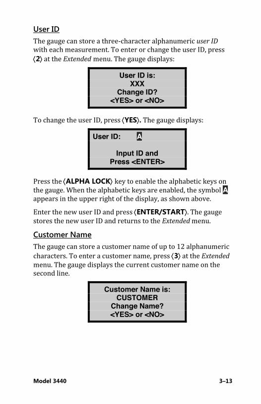
Press the ¢ALPHA LOCK² key to enable the alphabetic keys on the gauge. When the alphabetic keys are enabled, the symbol A appears in the upper right of the display, as shown above. Enter the new user ID and press ¢ENTER/START². The gauge stores the new user ID and returns to the Extended menu. Customer Name The gauge can store a customer name of up to 12 alphanumeric characters. To enter a customer name, press ¢3² at the Extended menu. The gauge displays the current customer name on the second line.
Customer Name is: CUSTOMER
Change Name? <YES> or <NO>

3–14
To change the customer name, press ¢YES². The gauge displays:
Customer Name: A
Input Name and Press <ENTER>
Press the ¢ALPHA LOCK² key to enable the alphabetic keys on the gauge. When the alphabetic keys are enabled, the symbol A appears in the upper right of the display, as shown above. Enter the new name and press the ¢ENTER/START² key. The gauge stores the new customer name, then returns to the Extended menu. Press ¢ESC² twice to return to the Ready screen.
Setting the Measurement Mode The gauge provides two measurement modes (Soil and Asphalt) for precise readings on base asphalt, concrete, soil, soil-stone aggregate, and similar materials. The gauge can also be used to determine the density of thin-layer overlays using the Nomograph function described on page 5–9. Before taking a measurement, select the appropriate measurement mode by pressing the ¢MODE² key. The gauge displays:
Mode: Asphalt 1. Asphalt 2. Soil
Press # to Select
NOTE
The ¢MODE² key is active only when the Ready screen is displayed.

Model 3440 4–15
CChhaapptteerr 44:: UUssiinngg tthhee GGaauuggee
This chapter covers the following topics and tasks:
9 Taking a standard count 9 Preparing a test site 9 Taking measurements 9 Using the Recall function

4–16
TTaakkiinngg tthhee SSttaannddaarrdd CCoouunntt The Model 3440 gauge uses a Cesium-137 and an Americium-241:Beryllium source for taking measurements. These radioactive sources undergo a natural decay process, resulting in a gradual loss in the intensity of their radiation. The time required for the source strength to diminish by 50% is referred to as the half-life. To compensate for the source decay and to check proper operation of the gauge, a daily reference standard count should be performed. To ensure the highest accuracy possible with the gauge, it is important to take a daily standard count. The gauge is equipped with a reference standard block for taking the standard count. Site Requirements Choose a standard count site that meets the following criteria: i A smooth, dry surface such that the reference standard
block does not rock. i At least 3 meters (10 ft.) from any large vertical surface. i At least 10 meters (33 ft.) from any other radioactive source. i On asphalt, concrete, or compacted soil at least 10
centimeters (4 in.) thick and with a density of at least 1600 kg/m3 (100 pcf).
NOTE
Always take standard counts using the reference standard block provided with the gauge.

Model 3440 4–17
To take a standard count: 11.. Ensure that the gauge base and reference standard block are
dry and free of debris. 22.. Place the reference standard block on the standard count
site. 33.. Ensure the source rod is in the SAFE position. 44.. As shown in Figure 9, place the gauge on the reference
standard block, with the right side (keypad side) of the gauge against the metal butt plate.
55.. From the Ready screen, press ¢STD². The gauge displays standard counts for density (DS) and moisture (MS):
Standard Count DS= #### MS= ####
Take New Count?
f To take a new standard count, press ¢YES² and follow the instructions starting at step 6 below.
f To view the last four standard counts, press ¢NO² and follow the instructions in the Viewing Standard Counts section on page 4–21.
66.. When taking a new standard count, the gauge displays:
Place Gauge on Std. Block & Source Rod in SAFE Pos. Press <ENTER>

4–18
Figure 9. Standard Count Position
77.. Begin the standard count by pressing the ¢ENTER/START² key. The gauge displays:
Taking Standard Count
### s Remaining
88.. After taking the standard count, the gauge displays the results:
DS= #### ##.#% P MS= #### ##.#% P
Do You Want to Use the New Std?

Model 3440 4–19
Recording the Standard Count Troxler recommends keeping a daily log of the moisture and density standard counts (see Appendix E for a sample log). To verify gauge stability, compare the daily standard count to a reliable reference as follows: i During the first four days of operation of a new or
recalibrated gauge, compare the daily standard count to the factory-calibrated values.
i After the first four days of operation (or after taking four standard counts), compare the daily standard count to the average of the last four counts. Acceptable standard count limits are: r1% each day for DS (density standard) and r2% each day for MS (moisture standard).
After recording the standard counts, press ¢YES² to return to the Ready mode.
NOTE
The factory standard count values should be used as a reference if the daily standard counts are ever in question. Be sure to refer to the most recent calibration report for the gauge in question.
4–20
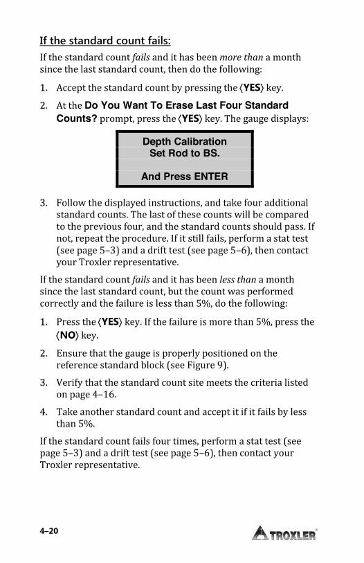
If the standard count fails: If the standard count fails and it has been more than a month since the last standard count, then do the following: 11.. Accept the standard count by pressing the ¢YES² key. 22.. At the Do You Want To Erase Last Four Standard
Counts? prompt, press the ¢YES² key. The gauge displays:
Depth Calibration Set Rod to BS.
And Press ENTER
33.. Follow the displayed instructions, and take four additional standard counts. The last of these counts will be compared to the previous four, and the standard counts should pass. If not, repeat the procedure. If it still fails, perform a stat test (see page 5–3) and a drift test (see page 5–6), then contact your Troxler representative.
If the standard count fails and it has been less than a month since the last standard count, but the count was performed correctly and the failure is less than 5%, do the following: 11.. Press the ¢YES² key. If the failure is more than 5%, press the
¢NO² key. 22.. Ensure that the gauge is properly positioned on the
reference standard block (see Figure 9). 33.. Verify that the standard count site meets the criteria listed
on page 4–16. 44.. Take another standard count and accept it if it fails by less
than 5%. If the standard count fails four times, perform a stat test (see page 5–3) and a drift test (see page 5–6), then contact your Troxler representative.
Model 3440 4–21
After the standard count passes, the operator can take measurements with the gauge. When not taking readings, always keep the source rod in the SAFE position. For added user safety, the source rod automatically retracts to the SAFE position when the gauge is lifted using the handle.
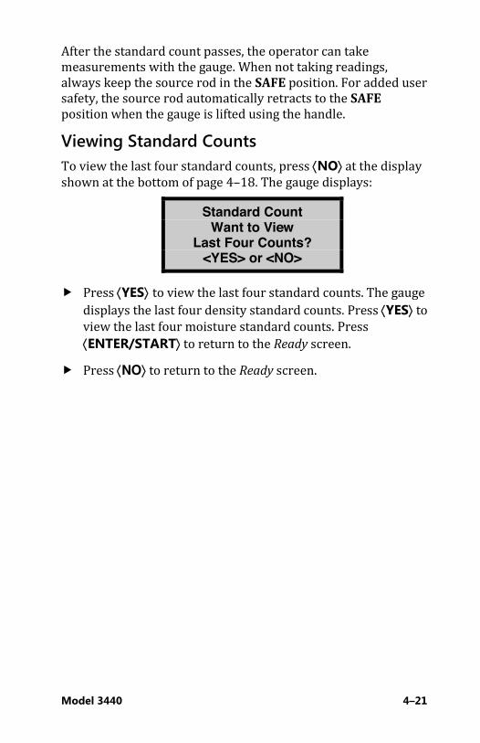
Viewing Standard Counts To view the last four standard counts, press ¢NO² at the display shown at the bottom of page 4–18. The gauge displays:
Standard Count Want to View
Last Four Counts? <YES> or <NO>
f Press ¢YES² to view the last four standard counts. The gauge displays the last four density standard counts. Press ¢YES² to view the last four moisture standard counts. Press ¢ENTER/START² to return to the Ready screen.
f Press ¢NO² to return to the Ready screen.
4–22
SSiittee PPrreeppaarraattiioonn Preparation of the test site surface is critical to gauge performance. This section provides site preparation procedures for both soils and base courses and asphalt surfaces. To ensure the most accurate gauge readings, the appropriate preparation procedure should be followed.
Soil and Base Course Preparation
11.. Locate a level site free from any large holes, cracks, or debris (soil surface conditions are critical to accurate measurements).
22.. Smooth the surface by moving the scraper plate in a back and forth motion. Filler such as fine sand may be used to fill in the surface voids.
CAUTION
Use only enough filler to fill the voids. Too much filler will cause an error in the measurement.
33.. For direct transmission measurements, put the drill rod through the extraction tool and then through one of the guides on the plate (see Figure 10).
WARNING!
Under no circumstances should you use the source rod of the gauge to drill holes.
44.. Wearing a radiation badge and safety glasses (or other locally approved safety devices), step on the plate and hammer the drill rod at least 50 mm (2 in.) deeper than the desired test depth. The drill rod increments include the additional depth.

Model 3440 4–23
Figure 10. Drill Rod Positioning
55.. Remove the drill rod by pulling straight up and twisting the extraction tool. Do not loosen the drill rod by tapping from side to side with a hammer. This will distort the hole or cause loose material to fall into the hole.
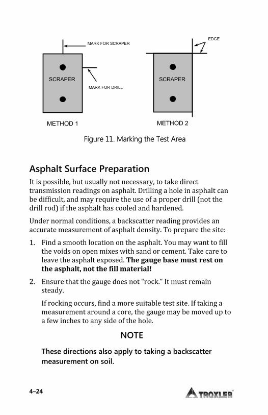
66.. To ensure accurate placement of the gauge, before removing the scraper plate, mark the test area using the drill rod as shown in Figure 11.
77.. Carefully pick up the scraper plate and place the gauge on the surface prepared by the plate. Insert the source rod into the hole made by the drill rod. Use care when inserting the source rod; do not to disturb the soil around the hole.
88.. Lower the source rod into the hole. Release the trigger and lock the source rod into the correct position. A click should be heard when the source rod is locked into position.
99.. Gently slide the gauge toward the keypad so the source rod makes contact with the wall of the hole.
4–24
Asphalt Surface Preparation It is possible, but usually not necessary, to take direct transmission readings on asphalt. Drilling a hole in asphalt can be difficult, and may require the use of a proper drill (not the drill rod) if the asphalt has cooled and hardened. Under normal conditions, a backscatter reading provides an accurate measurement of asphalt density. To prepare the site: 11.. Find a smooth location on the asphalt. You may want to fill
the voids on open mixes with sand or cement. Take care to leave the asphalt exposed. The gauge base must rest on the asphalt, not the fill material!
22.. Ensure that the gauge does not “rock.” It must remain steady. If rocking occurs, find a more suitable test site. If taking a measurement around a core, the gauge may be moved up to a few inches to any side of the hole.
NOTE
These directions also apply to taking a backscatter measurement on soil.
MARK FOR SCRAPER
PLATE CENTER
MARK FOR DRILL
ROD CENTER
METHOD 1
EDGE
MARKS
METHOD 2
SCRAPER
PLATE
SCRAPER
PLATE
Figure 11. Marking the Test Area
Model 3440 4–25
TTaakkiinngg MMeeaassuurreemmeennttss Soil Mode The Soil mode is automatically selected when a Proctor value is enabled (see page 3–9).
CAUTION
When not taking measurements, always keep the source rod in the SAFE position. For added operator safety, the source rod on the gauge automatically retracts to the SAFE position when the gauge is lifted by the handle.
If you do not hear a click when the gauge is raised to the SAFE position, look at the bottom of the gauge to verify that the tungsten sliding block is completely closed. If the gauge base opening is not completely closed by the sliding block, the block may require cleaning. Refer to page D-10 for cleaning instructions.
WARNING!
Do not store or transport the gauge unless the sliding block is completely closed. Increased radiation levels may violate transportation regulations and cause excessive personnel exposure.
The Status function (see page 3–8) allows you to view selected information concerning the current gauge status and setup. To access the Status function, press the ¢STATUS² key. Check the gauge’s current status before taking measurements. Remember to take a standard count at least once each day the gauge is to be used (see page 4–16). Note that some states may require that a standard count be taken more frequently than once per day.
4–26
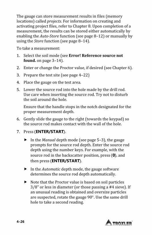
The gauge can store measurement results in files (memory locations) called projects. For information on creating and activating project files, refer to Chapter 8. Upon completion of a measurement, the results can be stored either automatically by enabling the Auto-Store function (see page 8–12) or manually by using the Store function (see page 8–14). To take a measurement: 11.. Select the soil mode (see Error! Reference source not
found. on page 3–14). 22.. Enter or change the Proctor value, if desired (see Chapter 6). 33.. Prepare the test site (see page 4–22) 44.. Place the gauge on the test area. 55.. Lower the source rod into the hole made by the drill rod.
Use care when inserting the source rod. Try not to disturb the soil around the hole. Ensure that the handle stops in the notch designated for the proper measurement depth.
66.. Gently slide the gauge to the right (towards the keypad) so the source rod makes contact with the wall of the hole.
77.. Press ¢ENTER/START². f In the Manual depth mode (see page 5–3), the gauge
prompts for the source rod depth. Enter the source rod depth using the number keys. For example, with the source rod in the backscatter position, press ¢0², and then press ¢ENTER/START².
f In the Automatic depth mode, the gauge software determines the source rod depth automatically.
f Note that the Proctor value is based on soil particles 3/8” or less in diameter (or those passing a #4 sieve). If an unusual reading is obtained and oversize particles are suspected, rotate the gauge 90q. Use the same drill hole to take a second reading.
Model 3440 4–27
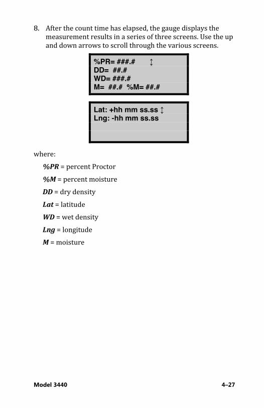
88.. After the count time has elapsed, the gauge displays the measurement results in a series of three screens. Use the up and down arrows to scroll through the various screens.
%PR= ###.# ↨ DD= ##.# WD= ###.# M= ##.# %M= ##.#
Lat: +hh mm ss.ss ↨ Lng: -hh mm ss.ss
where: %PR = percent Proctor %M = percent moisture DD = dry density Lat = latitude WD = wet density Lng = longitude M = moisture
4–28
NOTE
The latitude and longitude display, showing the location of the measurement, is available only on Model 3440 gauges equipped with the optional GPS and is shown only when it is enabled.
The latitude and longitude values denote the quality of the location fix. If WAAS information is available during a gauge measurement, the latitude and longitude will be displayed to the nearest hundredth (1/100) of a second.
If a GPS location is determined, but the WAAS information is unavailable, the latitude and longitude will be displayed to the nearest tenth (1/10) of a second.
If the GPS receiver cannot determine a location, the latitude and longitude will be denoted as 0. For more information on GPS accuracy, see Appendix H.
If a project is active and the Auto-Store function (see page 8–12) is enabled, press ¢ESC² or ¢ENTER/START² to continue. For each measurement, the gauge can store a location description of up to 12 characters, as well as a note of up to 15 characters. Follow the prompts to enter location information and/or a note. If a project is active but the Auto-Store function is not enabled:
f Press ¢STORE² to store the results. Follow the prompts to enter location information and/or notes. For more information on storing results manually, see page 8–14.
f Press ¢ESC² to return to the Ready screen without storing the results. Note that, until another measurement has been taken, the results can be recalled as described on page 4–31 and stored later.
Model 3440 4–29
99.. Lift the gauge from the test site by the source rod handle. This returns the source rod to the SAFE position, where it should stay when not taking readings.
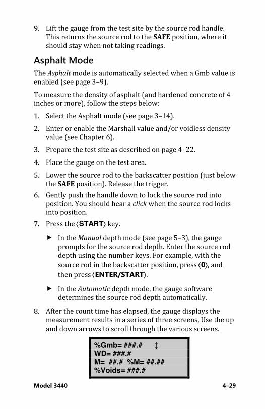
Asphalt Mode The Asphalt mode is automatically selected when a Gmb value is enabled (see page 3–9). To measure the density of asphalt (and hardened concrete of 4 inches or more), follow the steps below: 11.. Select the Asphalt mode (see page 3–14). 22.. Enter or enable the Marshall value and/or voidless density
value (see Chapter 6). 33.. Prepare the test site as described on page 4–22. 44.. Place the gauge on the test area. 55.. Lower the source rod to the backscatter position (just below
the SAFE position). Release the trigger. 66.. Gently push the handle down to lock the source rod into
position. You should hear a click when the source rod locks into position.
77.. Press the ¢START² key. f In the Manual depth mode (see page 5–3), the gauge
prompts for the source rod depth. Enter the source rod depth using the number keys. For example, with the source rod in the backscatter position, press ¢0², and then press ¢ENTER/START².
f In the Automatic depth mode, the gauge software determines the source rod depth automatically.
88.. After the count time has elapsed, the gauge displays the measurement results in a series of three screens, Use the up and down arrows to scroll through the various screens.
%Gmb= ###.# ↨ WD= ###.# M= ##.# %M= ##.## %Voids= ###.#
4–30
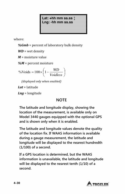
Lat: +hh mm ss.ss ↨ Lng: -hh mm ss.ss
where: %Gmb = percent of laboratory bulk density WD = wet density M = moisture value %M = percent moisture
¸¹·
¨©§ �u
VoidlessWD1100%Voids
(displayed only when enabled)
Lat = latitude Lng = longitude
NOTE
The latitude and longitude display, showing the location of the measurement, is available only on Model 3440 gauges equipped with the optional GPS and is shown only when it is enabled.
The latitude and longitude values denote the quality of the location fix. If WAAS information is available during a gauge measurement, the latitude and longitude will be displayed to the nearest hundredth (1/100) of a second.
If a GPS location is determined, but the WAAS information is unavailable, the latitude and longitude will be displayed to the nearest tenth (1/10) of a second.

Model 3440 4–31
If the GPS receiver cannot determine a location, the latitude and longitude will be denoted as 0. For more information on GPS accuracy, see Appendix H.
If a project is active (see Error! Reference source not found.) and the Auto-Store function (see page 8–12) is enabled, press ¢ESC² or ¢ENTER/START² to continue. For each measurement, the gauge can store a location description of up to 12 characters, as well as a note of up to 15 characters. Follow the prompts to enter location information and/or a note. If a project is active but the Auto-Store function is not enabled:
f Press ¢STORE² to store the results. Follow the prompts to enter location information and/or notes. For more information on storing results manually, see page 8–14.
f Press ¢ESC² to return to the Ready screen without storing the results. Note that, until another measurement has been taken, the results can be recalled as described on page 4–31 and stored later.
99.. Lift the gauge from the test site by the source rod handle. This returns the source rod to the SAFE position. When not taking readings, always keep the source rod in the SAFE position.
RReeccaallll To view the results of the most recent measurement, press the ¢RECALL² key from the Ready screen. The Recall function can also be used to view the gauge counts from the most recent measurement. To return to the Ready screen, press the ¢ENTER/START² key.
NOTE
The ¢RECALL² key is active only when the Ready screen is displayed.
Model 3440 5–1
CChhaapptteerr 55:: SSeettuupp MMeennuu
This chapter covers the following topics and tasks:
9 Overview of the Setup menu 9 Taking a stat test 9 Taking a drift test 9 Using the Nomograph function 9 Using the Precision function 9 Overview of optional features

5–2
SSeettuupp MMeennuu The gauge software groups most of the setup features into one menu. To access the Setup menu, press the ¢SETUP² key. The gauge displays:
-Setup- ↨ 1. Count Time 2. Set Units 3. Depth Mode
-Setup- ↨ 4. Stat Test 5. Drift Test 6. Nomograph
-Setup- ↨ 7. Precision 8. Options 9. Battery Status
-Setup- ↨ .0-% Voids (soil)
NOTE
The ¢SETUP² key is active only when the Ready screen is displayed.
Use the arrows keys to scroll through the menu screens. To select a menu option, use the number key that corresponds to that option. The remainder of this section provides details on the functions available from the Setup menu.

Model 3440 5–3
Count Time The gauge provides three different count times for taking measurements. To change the count time, see page 3–8.
Set Units The gauge can display measurement results in either U.S. units (pcf) or metric (SI) units (kg/m3 or g/cm3). To change the units, see page 3–9.
Depth Mode The Model 3440 gauge offers two depth modes: Automatic and Manual. The Depth Mode function allows the operator to set the depth mode, as described on page 3–9.
SSttaatt TTeesstt Erratic readings, or readings that seem to fluctuate, may indicate a problem with the gauge. If the readings are suspect, perform a stat test, or statistical stability test, to validate the normal operation of the gauge. A stat test consists of twenty 1-minute counts. From the twenty counts, the gauge calculates the standard deviation. This standard deviation is compared to a theoretical standard deviation value. Ideally, this ratio should be 0.25, with acceptable limits from 0.17 to 0.33. The gauge is considered unstable if the ratio is outside these limits and the stat test will fail. If the stat test fails, ensure that the gauge setup and testing was conducted correctly, and take an additional test. If the second test fails, contact the nearest Troxler service center for assistance. For a list of Troxler and authorized Troxler service centers, refer to page ii of this manual or visit the Troxler website at: www.troxlerlabs.com/services.
5–4
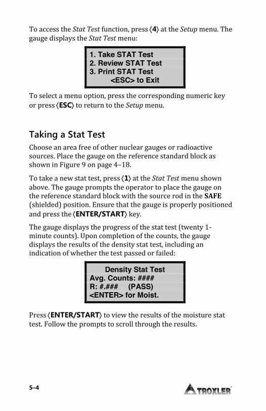
To access the Stat Test function, press ¢4² at the Setup menu. The gauge displays the Stat Test menu:
1. Take STAT Test 2. Review STAT Test 3. Print STAT Test
<ESC> to Exit
To select a menu option, press the corresponding numeric key or press ¢ESC² to return to the Setup menu.
Taking a Stat Test Choose an area free of other nuclear gauges or radioactive sources. Place the gauge on the reference standard block as shown in Figure 9 on page 4–18. To take a new stat test, press ¢1² at the Stat Test menu shown above. The gauge prompts the operator to place the gauge on the reference standard block with the source rod in the SAFE (shielded) position. Ensure that the gauge is properly positioned and press the ¢ENTER/START² key. The gauge displays the progress of the stat test (twenty 1-minute counts). Upon completion of the counts, the gauge displays the results of the density stat test, including an indication of whether the test passed or failed:
Density Stat Test Avg. Counts: #### R: #.### (PASS) <ENTER> for Moist.
Press ¢ENTER/START² to view the results of the moisture stat test. Follow the prompts to scroll through the results.
Model 3440 5–5
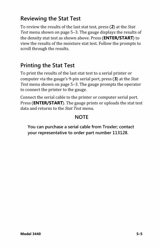
Reviewing the Stat Test To review the results of the last stat test, press ¢2² at the Stat
Test menu shown on page 5–3. The gauge displays the results of the density stat test as shown above. Press ¢ENTER/START² to view the results of the moisture stat test. Follow the prompts to scroll through the results.
Printing the Stat Test To print the results of the last stat test to a serial printer or computer via the gauge’s 9-pin serial port, press ¢3² at the Stat
Test menu shown on page 5–3. The gauge prompts the operator to connect the printer to the gauge. Connect the serial cable to the printer or computer serial port. Press ¢ENTER/START². The gauge prints or uploads the stat test data and returns to the Stat Test menu.
NOTE
You can purchase a serial cable from Troxler; contact your representative to order part number 113128.

5–6
DDrriifftt TTeesstt If the gauge passes the stat test, but shows long-term drift between measurements, perform a drift test to check the long-term drift of the gauge. A drift test consists of five counts taken three to eight hours after a stat test with no movement of the gauge between tests. The gauge sets the pass/fail limits based on the percent difference between the average of the stat test and drift test results. If the percent difference exceeds 0.5 percent for density counts or 1 percent for moisture counts, then the drift test fails. If the drift test fails, ensure that the gauge setup and testing were conducted correctly, and take an additional test. If the second test fails, contact the nearest Troxler service center for assistance. For a list of Troxler and authorized Troxler service centers, refer to page ii of this manual or visit the Troxler website at: www.troxlerlabs.com/services.
NOTE
The drift test consists of five 4-minute counts, whereas the stat test consists of twenty 1-minute counts. Therefore, each test takes approximately 20 minutes to conduct.
DO NOT turn the gauge off between a stat test and a drift test.
DO NOT move the gauge between the stat and drift tests to eliminate possible failure due to positioning changes.
Model 3440 5–7
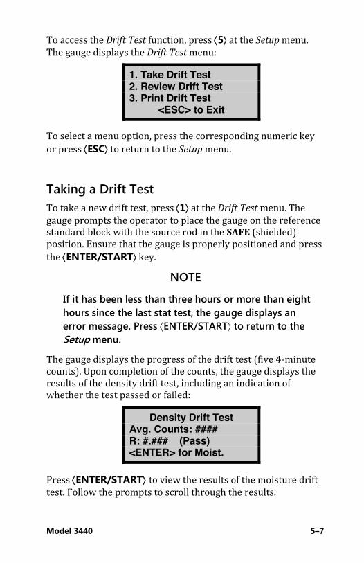
To access the Drift Test function, press ¢5² at the Setup menu. The gauge displays the Drift Test menu:
1. Take Drift Test 2. Review Drift Test 3. Print Drift Test
<ESC> to Exit
To select a menu option, press the corresponding numeric key or press ¢ESC² to return to the Setup menu.
Taking a Drift Test To take a new drift test, press ¢1² at the Drift Test menu. The gauge prompts the operator to place the gauge on the reference standard block with the source rod in the SAFE (shielded) position. Ensure that the gauge is properly positioned and press the ¢ENTER/START² key.
NOTE
If it has been less than three hours or more than eight hours since the last stat test, the gauge displays an error message. Press ¢ENTER/START² to return to the Setup menu.
The gauge displays the progress of the drift test (five 4-minute counts). Upon completion of the counts, the gauge displays the results of the density drift test, including an indication of whether the test passed or failed:
Density Drift Test Avg. Counts: #### R: #.### (Pass) <ENTER> for Moist.
Press ¢ENTER/START² to view the results of the moisture drift test. Follow the prompts to scroll through the results.
5–8
Reviewing the Drift Test To review the results of the drift stat test, press ¢2² at the Drift
Test menu. The gauge displays the results of the density drift test. Press ¢ENTER/START² to view the results of the moisture drift test. Follow the prompts to scroll through the results.
Printing the Drift Test To print the results of the last drift test to a serial printer or computer via the gauge’s 9-pin serial port, press ¢3² at the Drift
Test menu. The gauge prompts the operator to connect the printer to the gauge. Connect the serial cable to the printer or computer serial port. Press ¢ENTER/START². The gauge prints or uploads the drift test data and returns to the Drift Test menu.
NOTE
You can purchase a serial cable from Troxler; contact your representative to order part number 113128.

Model 3440 5–9
NNoommooggrraapphh In some cases, the gauge may be used to determine the density of thin asphalt overlays. This measurement may be performed with the gauge in backscatter mode and using the Nomograph method of density measurement. It should be noted that this method is not as accurate as a true thin-layer gauge. However, this method may produce satisfactory results under many conditions. When a nuclear gauge is used in backscatter mode on overlays under 3 in. (7.5 cm), several effects must be overcome to produce an accurate reading. With most gauges, the primary problem is the result of photons from the source penetrating deeper than 3 in. (7.5 cm) and scattering back to the gauge. These backscattered photons from the underlying material will adversely influence the reading. Obtaining an accurate overlay density with the Nomograph method requires that the density of the bottom layer and the thickness of the top layer be determined. The simplest method of determining the density of the bottom layer is to take a nuclear gauge measurement prior to applying the top layer or overlay. With the overlay applied and compacted, the depth of the layer should be determined. At this time, the gauge may be used to calculate the overlay layer density. To access the Nomograph function, press ¢6² at the Setup menu. The gauge displays:
Nomograph: OFF 1. Enable 2. Disable 3. Chg/View Data
From this menu, the operator may enable, disable, or change the Nomograph function, as described in the following sections.
5–10
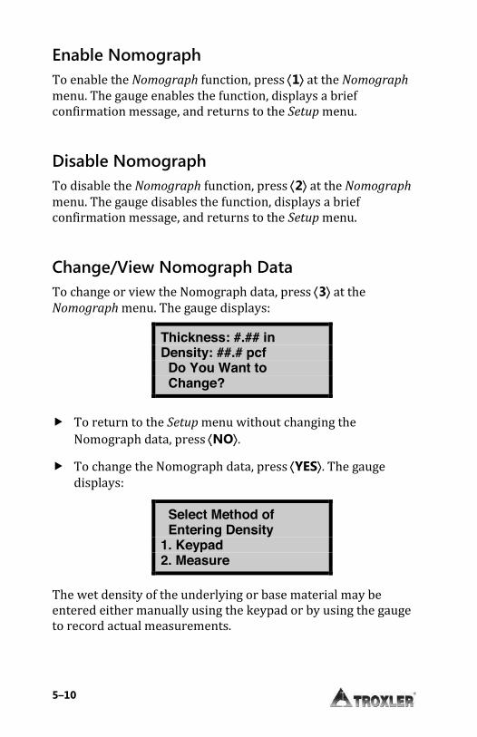
Enable Nomograph To enable the Nomograph function, press ¢1² at the Nomograph menu. The gauge enables the function, displays a brief confirmation message, and returns to the Setup menu.
Disable Nomograph To disable the Nomograph function, press ¢2² at the Nomograph menu. The gauge disables the function, displays a brief confirmation message, and returns to the Setup menu.
Change/View Nomograph Data To change or view the Nomograph data, press ¢3² at the Nomograph menu. The gauge displays:
Thickness: #.## in Density: ##.# pcf Do You Want to Change?
f To return to the Setup menu without changing the Nomograph data, press ¢NO².
f To change the Nomograph data, press ¢YES². The gauge displays:
Select Method of Entering Density 1. Keypad 2. Measure
The wet density of the underlying or base material may be entered either manually using the keypad or by using the gauge to record actual measurements.

Model 3440 5–11
Entering Density Using the Keypad To enter the density using the keypad, press ¢1² at the Select Method of Entering Density display. The gauge displays:
Overlay Thickness #.## in
Input and <ENTER>
Enter the thickness of the overlay (0–10 in.) and press ¢ENTER/START². The gauge displays:
Bottom Density #.# pcf
Input and <ENTER>
Enter the wet density of the bottom layer. The gauge enables the Nomograph function using the entered values, displays a brief confirmation message, and returns to the Setup menu. Entering Density Using Gauge Measurements Bottom density values may be obtained by using the gauge to record up to 20 actual measurements. To enter the density using this method, press ¢2² at the Select Method of Entering
Density menu. The gauge displays:
# of Readings to Average (1-20)?
# Input and <ENTER>

5–12
Enter the number of readings to be taken and averaged, then press ¢ENTER/START². The gauge displays:
Readings: # Time: # m
Place Rod to BS & Press <START>
Prepare the site for measurement as described on page 4–22. Position the gauge and press ¢ENTER/START². The gauge displays:
Nomograph Reading: 1 Depth: BS Time: ## s
After counting down to zero, the gauge displays:
Reading: 1 WD= ### pcf
Move Gauge and Press <START>
If more than one reading is to be taken, move the gauge to the next location and press ¢ENTER/START². The gauge will repeat the above sequence for each reading. When all the readings are completed, the display will be:
Average of # Redings ### pcf
Press <ENTER>
Press ¢ENTER/START² to continue. The gauge enables the Nomograph function, displays a brief confirmation message, and returns to the Setup menu.
Model 3440 5–13
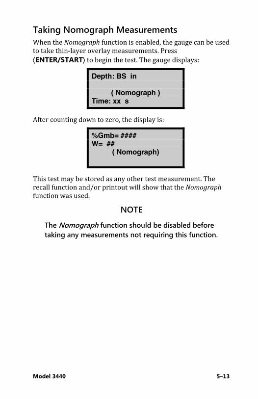
Taking Nomograph Measurements When the Nomograph function is enabled, the gauge can be used to take thin-layer overlay measurements. Press ¢ENTER/START² to begin the test. The gauge displays:
Depth: BS in
( Nomograph ) Time: xx s
After counting down to zero, the display is:
%Gmb= #### W= ##
( Nomograph)
This test may be stored as any other test measurement. The recall function and/or printout will show that the Nomograph function was used.
NOTE
The Nomograph function should be disabled before taking any measurements not requiring this function.
5–14
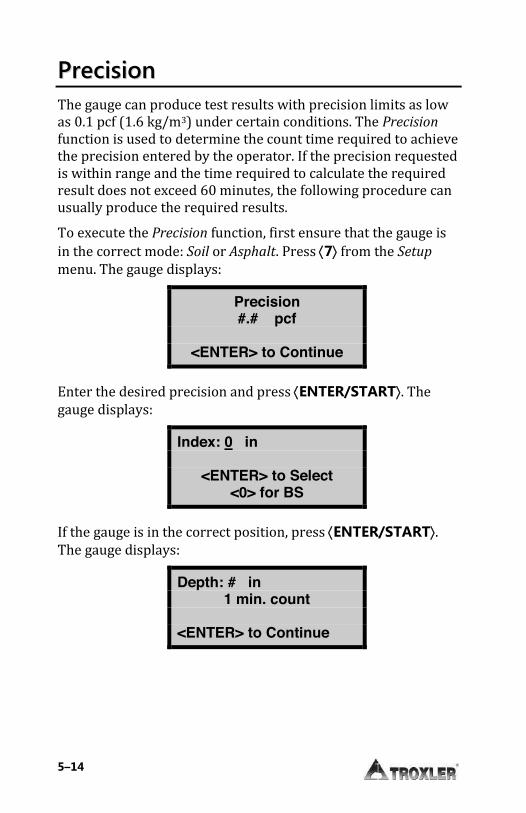
PPrreecciissiioonn The gauge can produce test results with precision limits as low as 0.1 pcf (1.6 kg/m3) under certain conditions. The Precision
function is used to determine the count time required to achieve the precision entered by the operator. If the precision requested is within range and the time required to calculate the required result does not exceed 60 minutes, the following procedure can usually produce the required results. To execute the Precision function, first ensure that the gauge is in the correct mode: Soil or Asphalt. Press ¢7² from the Setup menu. The gauge displays:
Precision #.# pcf
<ENTER> to Continue
Enter the desired precision and press ¢ENTER/START². The gauge displays:
Index: 0 in
<ENTER> to Select <0> for BS
If the gauge is in the correct position, press ¢ENTER/START². The gauge displays:
Depth: # in 1 min. count
<ENTER> to Continue

Model 3440 5–15
Press ¢ENTER/START². The gauge displays:
Precision Mode Depth: # in Time: ## s
# min. count
After counting down to zero, the display is:
## min. to Reach precision. <ESC> to Abort
<ENTER> to Continue
To abort this operation and return to the Setup menu, press ¢ESC². To continue with the Precision function, press ¢ENTER/START². After counting down, the display is: (For Soil mode)
%PR= ###.# DD= ###.# WD= ###.# M= ##.# %M= ##.#
(For Asphalt mode)
%Gmb= ###.# WD= ###.# M= ##.# %M= ##.# %Voids= ###.#
NOTE
If the required precision cannot be reached in 60 minutes, the gauge halts the count and displays a warning message.
5–16
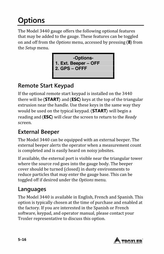
OOppttiioonnss The Model 3440 gauge offers the following optional features that may be added to the gauge. These features can be toggled on and off from the Options menu, accessed by pressing ¢8² from the Setup menu.
-Options- 1. Ext. Beeper – OFF 2. GPS – OFFF
Remote Start Keypad If the optional remote start keypad is installed on the 3440 there will be ¢START² and ¢ESC² keys at the top of the triangular extrusion near the handle. Use these keys in the same way they would be used on the typical keypad. ¢START² will begin a reading and ¢ESC² will clear the screen to return to the Ready screen.
External Beeper The Model 3440 can be equipped with an external beeper. The external beeper alerts the operator when a measurement count is completed and is easily heard on noisy jobsites. If available, the external port is visible near the triangular tower where the source rod goes into the gauge body. The beeper cover should be turned (closed) in dusty environments to reduce particles that may enter the gauge base. This can be toggled off if desired under the Options menu.
Languages The Model 3440 is available in English, French and Spanish. This option is typically chosen at the time of purchase and enabled at the factory. If you are interested in the Spanish or French software, keypad, and operator manual, please contact your Troxler representative to discuss this option.
Model 3440 5–17
Backlit Keypad
This option allows the keypad to be seen more easily in dimly lit environments. To activate the keypad backlight, press the ¢Light² key. Using the backlight reduces battery life, so it is important to turn it when not in use.
GPS Option The Model 3440 gauge can also be equipped with an optional global positioning system (GPS) receiver. The GPS receiver enables the gauge to store precise GPS coordinates, along with the standard date and time stamp, for each measurement. To toggle the GPS function on or off, press ¢2² on the Options menu shown above.
NOTE
When the GPS option is installed and enabled, the symbol g appears in the upper right of the Ready screen when the gauge is receiving GPS satellite signals.
NOTE
If a Model 3440 equipped with the GPS option is moved a long distance between uses, the GPS system must be allowed to initialize. In some instances, initialization may take as long as 30 to 45 minutes from the time the gauge is powered on with the GPS enabled. Note also that the gauge must be positioned such that the GPS receiver can receive signals from the GPS satellites (see Appendix H for more information). If the GPS does not initialize within 45 minutes, contact your Troxler representative.

5–18
Battery Status The Battery Status function displays the voltage of the NiMH batteries. To access this function, press ¢9² at the Setup menu. For more information, see the Battery Status section on page C–11.
PPeerrcceenntt AAiirr VVooiiddss ((SSooiill MMooddee)) The gauge uses the specific gravity function to calculate percent air voids and void ratio in Soil mode only. The % Voids function allows the operator to enter the specific gravity of a material and disable or enable the percent air voids display.
NOTE
To display percent air voids in Asphalt mode, enter a voidless density target value (see the Target Values section on page 6–3).
To access the % Voids function, press ¢.² ¢0² at the Setup menu. The gauge displays:
%Voids (soil): OFF SG: #.## 1. Enable 2. Disable 3. Change Target
The current specific gravity (default 2.70) is shown on the second line of the display. For optimum results, use a specific gravity value that is appropriate for the material being measured.
f To enable the current specific gravity value, press ¢1². The gauge enables the value, displays a brief confirmation message, and returns to the Setup menu.
f To disable the current specific gravity, press ¢2². The gauge disables the value, displays a brief confirmation message, and then returns to the Setup menu.

Model 3440 5–19
f To enter a new specific gravity value, press ¢3². The gauge prompts the operator for a new specific gravity. If the displayed specific gravity is acceptable, press the ¢ENTER/START² key. To change the value, use the numeric keys to do so, then press the ¢ENTER/START² key. In either case, the gauge enables the value, displays a brief confirmation message, and then returns to the Setup menu.
Model 3440 6–1
CChhaapptteerr 66:: TTaarrggeett MMeennuu
This chapter covers the following topics and tasks:
9 Overview of the Target menu 9 Enabling and disabling the target value 9 Storing a new target value
6–2
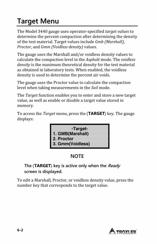
TTaarrggeett MMeennuu The Model 3440 gauge uses operator-specified target values to determine the percent compaction after determining the density of the test material. Target values include Gmb (Marshall), Proctor, and Gmm (Voidless density) values. The gauge uses the Marshall and/or voidless density values to calculate the compaction level in the Asphalt mode. The voidless
density is the maximum theoretical density for the test material as obtained in laboratory tests. When enabled, the voidless density is used to determine the percent air voids. The gauge uses the Proctor value to calculate the compaction level when taking measurements in the Soil mode. The Target function enables you to enter and store a new target value, as well as enable or disable a target value stored in memory. To access the Target menu, press the ¢TARGET² key. The gauge displays:
-Target- 1. GMB(Marshall) 2. Proctor 3. Gmm(Voidless)
NOTE
The ¢TARGET² key is active only when the Ready screen is displayed.
To edit a Marshall, Proctor, or voidless density value, press the number key that corresponds to the target value.
Model 3440 6–3
TTaarrggeett VVaalluueess NOTE
Because the menus for managing the Gmb (Marshall), Proctor, and Gmm (Voidless density) values are essentially the same, the following sections describe only the Gmb (Marshall) menu.
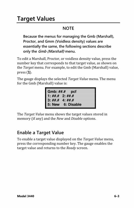
To edit a Marshall, Proctor, or voidless density value, press the number key that corresponds to that target value, as shown on the Target menu. For example, to edit the Gmb (Marshall) value, press ¢1². The gauge displays the selected Target Value menu. The menu for the Gmb (Marshall) value is:
Gmb: ##.# pcf 1: ##.# 2: ##.# 3: ##.# 4: ##.# 5: New 6: Disable
The Target Value menu shows the target values stored in memory (if any) and the New and Disable options.
Enable a Target Value To enable a target value displayed on the Target Value menu, press the corresponding number key. The gauge enables the target value and returns to the Ready screen.
6–4
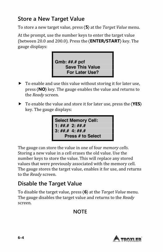
Store a New Target Value To store a new target value, press ¢5² at the Target Value menu. At the prompt, use the number keys to enter the target value (between 20.0 and 200.0). Press the ¢ENTER/START² key. The gauge displays:
Gmb: ##.# pcf
Save This Value For Later Use?
f To enable and use this value without storing it for later use, press ¢NO² key. The gauge enables the value and returns to the Ready screen.
f To enable the value and store it for later use, press the ¢YES² key. The gauge displays:
Select Memory Cell: 1: ##.# 2: ##.# 3: ##.# 4: ##.#
Press # to Select
The gauge can store the value in one of four memory cells. Storing a new value in a cell erases the old value. Use the number keys to store the value. This will replace any stored values that were previously associated with the memory cell. The gauge stores the target value, enables it for use, and returns to the Ready screen.
Disable the Target Value To disable the target value, press ¢6² at the Target Value menu. The gauge disables the target value and returns to the Ready screen.
NOTE

Model 3440 6–5
The gauge can be used with the target value disabled. In this case, no percent compaction value will be displayed.
Model 3440 7–1
CChhaapptteerr 77:: CCaalliibbrraattiioonn OOffffsseettss
This chapter covers the following topics and tasks:
9 Overview of the offset menu 9 Enabling density, moisture, and trench offsets

7–2
AAbboouutt OOffffsseettss The Model 3440 is factory-calibrated for soils, asphalt, and concrete with an approximate density range of 1100 to 2700 kg/m3 (70 to 170 pcf). With an offset, you can adjust the gauge readings to correlate to traditional laboratory methods, such as core samples. The Model 3440 gauge provides three offsets: density, moisture, and trench.
NOTE
When an offset has been enabled, all future readings will automatically be adjusted with the offset factor regardless of the test site. It is very important that you disable the offset function prior to taking readings on materials that do not require an offset. Offsets are disabled if the gauge is turned off for more than 10 seconds.
Density offsets are common when the material being measured is outside the range of 70 to 170 pcf (1121 to 2723 kg/m3) or if the material composition varies from average soil/asphalt on which the factory calibration is based. Moisture offsets are required for accurate measurements if the material to be measured contains elements that can cause the gauge to yield erroneous results. A negative offset is required if the material to be measured is high in hydrogenous components such as cement, gypsum, coal, or lime. A positive offset is required if the material is high in neutron-absorbing material such as boron or cadmium. The Model 3440 gauge requires a trench offset if measurements are to be taken inside a trench or close to vertical structures. Vertical structures can scatter neutrons and gamma photons back to the gauge, increasing the possibility of moisture or density errors due to high counts.
NOTE
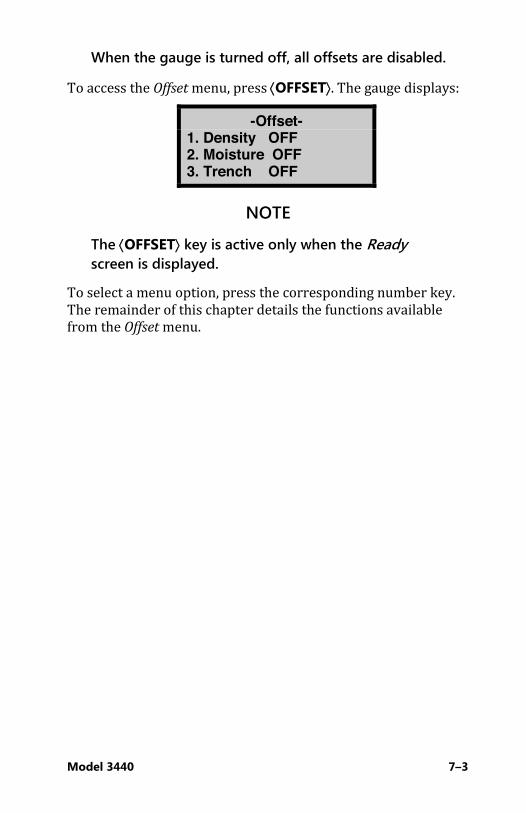
Model 3440 7–3
When the gauge is turned off, all offsets are disabled.
To access the Offset menu, press ¢OFFSET². The gauge displays:
-Offset- 1. Density OFF 2. Moisture OFF 3. Trench OFF
NOTE
The ¢OFFSET² key is active only when the Ready screen is displayed.
To select a menu option, press the corresponding number key. The remainder of this chapter details the functions available from the Offset menu.
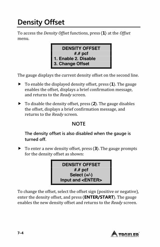
7–4
DDeennssiittyy OOffffsseett To access the Density Offset functions, press ¢1² at the Offset menu.
DENSITY OFFSET #.# pcf
1. Enable 2. Disable 3. Change Offset
The gauge displays the current density offset on the second line.
f To enable the displayed density offset, press ¢1². The gauge enables the offset, displays a brief confirmation message, and returns to the Ready screen.
f To disable the density offset, press ¢2². The gauge disables the offset, displays a brief confirmation message, and returns to the Ready screen.
NOTE
The density offset is also disabled when the gauge is turned off.
f To enter a new density offset, press ¢3². The gauge prompts for the density offset as shown:
DENSITY OFFSET #.# pcf
Select (+/-) Input and <ENTER>
To change the offset, select the offset sign (positive or negative), enter the density offset, and press ¢ENTER/START². The gauge enables the new density offset and returns to the Ready screen.
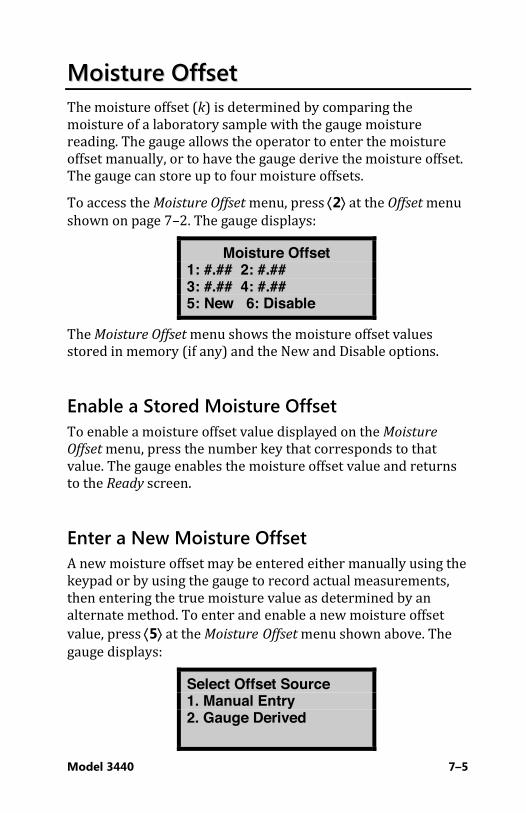
Model 3440 7–5
MMooiissttuurree OOffffsseett The moisture offset (k) is determined by comparing the moisture of a laboratory sample with the gauge moisture reading. The gauge allows the operator to enter the moisture offset manually, or to have the gauge derive the moisture offset. The gauge can store up to four moisture offsets. To access the Moisture Offset menu, press ¢2² at the Offset menu shown on page 7–2. The gauge displays:
Moisture Offset 1: #.## 2: #.## 3: #.## 4: #.## 5: New 6: Disable
The Moisture Offset menu shows the moisture offset values stored in memory (if any) and the New and Disable options.
Enable a Stored Moisture Offset To enable a moisture offset value displayed on the Moisture
Offset menu, press the number key that corresponds to that value. The gauge enables the moisture offset value and returns to the Ready screen.
Enter a New Moisture Offset A new moisture offset may be entered either manually using the keypad or by using the gauge to record actual measurements, then entering the true moisture value as determined by an alternate method. To enter and enable a new moisture offset value, press ¢5² at the Moisture Offset menu shown above. The gauge displays:
Select Offset Source 1. Manual Entry 2. Gauge Derived

7–6
Enter a Moisture Offset (Manual Entry) To enter a new moisture value manually via the keypad, first determine the true moisture content of a sample taken at the measurement site using standard laboratory methods (for example, oven drying, and so on). Take multiple readings at or near the location where the sample was removed and record the moisture measurements. Calculate the average moisture of the readings to determine the gauge
moisture content. To enter the moisture offset manually, press ¢1² at the Select Offset Source menu shown on page 7–5. The gauge request the true moisture value as shown:
True Moisture % #.##
Press <ENTER>
Enter the true moisture value and press ¢ENTER/START². The gauge requests the gauge moisture value as shown:
Gauge Moisture % #.##
Press <ENTER>
Enter the gauge moisture value and press ¢ENTER/START². The gauge calculates and displays the moisture offset (k) as shown:
K: #.## Save This Value For Later Use?
f To enable and use this moisture offset without storing it for later use, press ¢NO². The gauge enables the offset and returns to the Ready screen.

Model 3440 7–7
f To enable the moisture offset and store it for later use, press ¢YES². The gauge displays:
Select Memory Cell: 1: #.## 2: #.## 3: #.## 4: #.##
Press # to Select
The gauge can store the value in one of four memory cells. Storing a new value in a cell erases the old value. Use the number keys to store the value. This will replace any stored values that were previously associated with the memory cell. The gauge stores the moisture offset, enables it for use, and returns to the Ready screen. Gauge-Derived Moisture Offset To allow the gauge to derive the moisture offset, you must determine the true moisture content of a sample taken at the measurement site using standard laboratory methods (for example, oven drying, and so on), then take readings with the gauge. To use this method of determining the moisture offset, press ¢2² at the Select Offset Source menu shown on page 7–5. The gauge request the true moisture value as shown:
True Moisture % ##.#
Press <ENTER>
Enter the true moisture value and press ¢ENTER/START². The gauge displays:
Place gauge on soil, lower rod and press any key

7–8
As prompted, place the gauge on the measurement site and press any key. The gauge takes a 240-second count, during which it displays the progress of the count. Upon completion, the gauge calculates and displays the moisture offset (k) as shown:
K: ##.## Save This Value For Later Use?
f To enable and use this moisture offset without storing it for later use, press ¢NO². The gauge enables the offset and returns to the Ready screen.
f To enable the moisture offset and store it for later use, press ¢YES². The gauge displays:
Select Memory Cell: 1: #.## 2: #.## 3: #.## 4: #.##
Press # to Select
The gauge can store the value in one of four memory cells. Storing a new value in a cell erases the old value. Use the number keys to store the value. This will replace any stored values that were previously associated with the memory cell. The gauge stores the moisture offset, enables it for use, and returns to the Ready screen.
Disable the Moisture Offset To disable the moisture offset value, press ¢6² at the Moisture Offset menu. The gauge disables the moisture offset and returns to the Ready screen.
NOTE
The moisture offset is also disabled when the gauge is turned off.

Model 3440 7–9
TTrreenncchh OOffffsseett To use the gauge in a trench or within 0.6 m (2 ft.) of a large vertical surface, first perform a trench offset. The trench offset adjusts all moisture measurements and density measurements from backscatter to 4 inches. For direct transmission measurements over 4 inches deep, the gauge will only adjust the moisture measurements. In the displays shown below, M refers to trench moisture offset; D refers to trench density offset values.
NOTE
Before determining a new trench offset, ensure that a standard count has been performed recently outside the trench.
To access the Trench Offset menu, press ¢3² at the Offset menu. The gauge displays:
Trench Offset M: # D: #
1. Enable 2. Disable 3. Change Offset
The gauge displays the current offset values on the second line.
f To enable the displayed trench offset, press ¢1². The gauge enables the offset, displays a brief confirmation message, and returns to the Ready screen.
f To disable the trench offset, press ¢2². The gauge disables the offset, displays a brief confirmation message, and returns to the Ready screen.
NOTE
The trench offset is also disabled when the gauge is turned off.

7–10
f To enter a new trench offset, press ¢3². The gauge displays:
Place Gauge in trench on Std.
block in SAFE Pos. Press <START>
Select a position inside the trench and the same distance from the wall as the test measurements. Place the gauge on the standard block in this position, set the source rod to the SAFE position, and press ¢ENTER/START². The gauge performs a trench count, calculates the trench moisture and density offset values, enables the trench offset, and returns to the Ready screen.
Model 3440 8–1
CChhaapptteerr 88:: PPrroojjeecctt DDaattaa
This chapter covers the following topics and tasks:
9 Overview of the Project menu 9 Selecting and viewing projects 9 Creating new projects 9 Erasing projects 9 Outputting and printing projects 9 Deactivating projects 9 Using the Auto-Store feature 9 Using the Manual Store feature
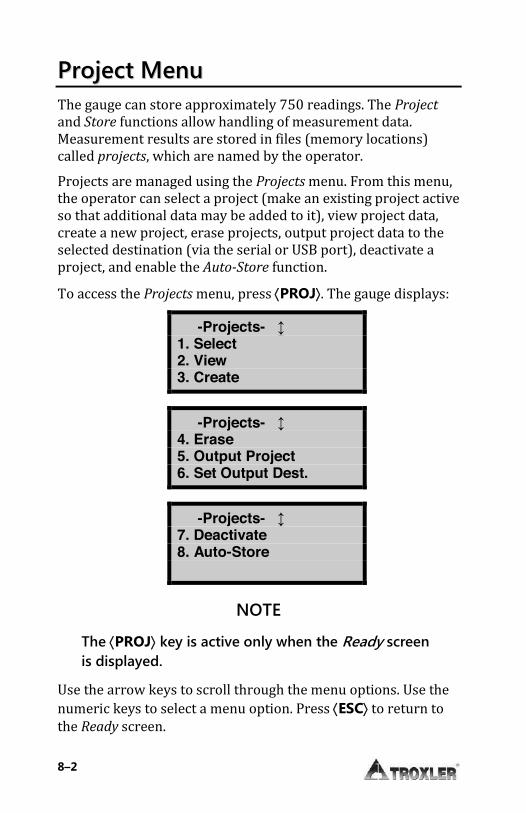
8–2
PPrroojjeecctt MMeennuu The gauge can store approximately 750 readings. The Project and Store functions allow handling of measurement data. Measurement results are stored in files (memory locations) called projects, which are named by the operator. Projects are managed using the Projects menu. From this menu, the operator can select a project (make an existing project active so that additional data may be added to it), view project data, create a new project, erase projects, output project data to the selected destination (via the serial or USB port), deactivate a project, and enable the Auto-Store function. To access the Projects menu, press ¢PROJ². The gauge displays:
-Projects- ↨ 1. Select 2. View 3. Create
-Projects- ↨ 4. Erase 5. Output Project 6. Set Output Dest.
-Projects- ↨ 7. Deactivate 8. Auto-Store
NOTE
The ¢PROJ² key is active only when the Ready screen is displayed.
Use the arrow keys to scroll through the menu options. Use the numeric keys to select a menu option. Press ¢ESC² to return to the Ready screen.
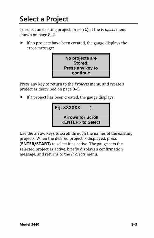
Model 3440 8–3
SSeelleecctt aa PPrroojjeecctt To select an existing project, press ¢1² at the Projects menu shown on page 8–2. f If no projects have been created, the gauge displays the
error message:
No projects are Stored.
Press any key to continue
Press any key to return to the Projects menu, and create a project as described on page 8–5. f If a project has been created, the gauge displays:
Prj: XXXXXX ↨
Arrows for Scroll <ENTER> to Select
Use the arrow keys to scroll through the names of the existing projects. When the desired project is displayed, press ¢ENTER/START² to select it as active. The gauge sets the selected project as active, briefly displays a confirmation message, and returns to the Projects menu.
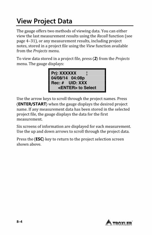
8–4
VViieeww PPrroojjeecctt DDaattaa The gauge offers two methods of viewing data. You can either view the last measurement results using the Recall function (see page 4–31), or any measurement results, including project notes, stored in a project file using the View function available from the Projects menu. To view data stored in a project file, press ¢2² from the Projects menu. The gauge displays:
Prj: XXXXXX ↨ 04/08/14 04:08p Rec: # UID: XXX
<ENTER> to Select
Use the arrow keys to scroll through the project names. Press ¢ENTER/START² when the gauge displays the desired project name. If any measurement data has been stored in the selected project file, the gauge displays the data for the first measurement. Six screens of information are displayed for each measurement. Use the up and down arrows to scroll through the project data. Press the ¢ESC² key to return to the project selection screen shown above.
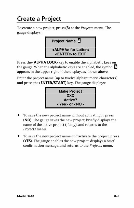
Model 3440 8–5
CCrreeaattee aa PPrroojjeecctt To create a new project, press ¢3² at the Projects menu. The gauge displays:
Project Name A _
<ALPHA> for Letters <ENTER> to EXIT
Press the ¢ALPHA LOCK² key to enable the alphabetic keys on the gauge. When the alphabetic keys are enabled, the symbol A appears in the upper right of the display, as shown above. Enter the project name (up to twelve alphanumeric characters) and press the ¢ENTER/START² key. The gauge displays:
Make Project XXX
Active? <Yes> or <NO>
f To save the new project name without activating it, press ¢NO². The gauge saves the new project, briefly displays the name of the active project (if any), and returns to the Projects menu.
f To save the new project name and activate the project, press ¢YES². The gauge enables the new project, displays a brief confirmation message, and returns to the Projects menu.

8–6
EErraassee PPrroojjeeccttss To erase either a selected project file or all project files, press ¢4² at the Projects menu. The gauge displays the Erase menu:
Erase: 1. One Project 2. All Projects
Press # to Select
f To erase a single project, press ¢1². If more than one project has been created, the gauge displays:
Prj: XXXXXX ↨
Arrows for Scroll <ENTER> to Select
Use the arrow keys to scroll through the project names displayed on the first line. When the gauge displays the desired project, press ¢ENTER/START². At the Are you sure? prompt, press the ¢YES² key. The gauge erases the project and returns to the Projects menu.
f To erase all projects, press ¢2² at the Erase menu. At the Are You Sure? prompt, press the ¢YES² key. The gauge erases all the projects and returns to the Projects menu.

Model 3440 8–7
OOuuttppuutt PPrroojjeecctt The Output Project function within the Projects menu allows the operator to print or upload project data stored in the gauge to a computer or serial printer connected to the serial port, or to a USB printer or flash drive connected to the USB port. To select the output destination, see page 8–11.
NOTE
The USB port is included only on Model 3440 gauges.
Uploading or Printing Project Data You can upload project data to a computer via the serial port using Troxler’s Gauge Download Program, available at: www.troxlerlabs.com/downloads/software/gaugedownload.zip You can also upload the data using Windows® HyperTerminal or TerraTerm. See the “Downloading Data” procedure at www.troxlerlabs.com/documents for HyperTerminal instructions. To output project data via the 9-pin serial port, connect a serial cable to the port. An optional serial cable, P/N 113128, is available from Troxler. Connect the serial cable to the computer’s COM port (or a printer’s serial port). To output project data to a USB printer via the USB port, connect a USB cable to the USB port and connect the cable to the USB printer. To output project data to a USB flash drive, connect the flash drive directly to the USB port.
NOTE
The opening for the USB port will accept a device with maximum dimensions of 10 mm (0.40 in.) high by 29 mm (0.79 in.) wide.
A list of compatible USB devices is available at: www.troxlerlabs.com/documents

8–8
At the Projects menu, press ¢5². The gauge request the output format as shown:
Output: 1. 32 Column Report 2. Spreadsheet
Press # to Select
The 32 Column Report option is formatted for a standard printer width. This format is recommended when outputting the data to a printer. The Spreadsheet option is sent in a comma-delimited format, which can then be imported easily into a spreadsheet program, such as Microsoft Excel�. Table 2 on page 8–10 defines the information contained in each column of the spreadsheet. Press ¢1² or ¢2² to select the desired output format. The gauge displays:
Output: 1. One Project 2. All Projects
Press # to Select
From this menu, the gauge can print (or upload) either a single project or all projects.
f To output a single project, press ¢1². The gauge displays:
Prj: XXXXXX ↨
Arrows for Scroll <ENTER> to Select
Use the arrow keys to scroll through the project names displayed on the first line. When the gauge displays the desired project, press ¢ENTER/START².
f To output the data from all projects, press ¢2².

Model 3440 8–9
The gauge prints (or uploads) the selected project(s) and returns to the Projects menu. Press the ¢ESC² key to return to the Ready screen.
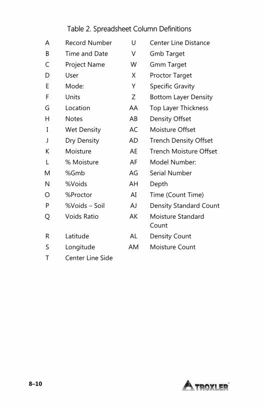
8–10
Table 2. Spreadsheet Column Definitions
A Record Number U Center Line Distance
B Time and Date V Gmb Target
C Project Name W Gmm Target
D User X Proctor Target
E Mode: Y Specific Gravity
F Units Z Bottom Layer Density
G Location AA Top Layer Thickness
H Notes AB Density Offset
I Wet Density AC Moisture Offset
J Dry Density AD Trench Density Offset
K Moisture AE Trench Moisture Offset
L % Moisture AF Model Number:
M %Gmb AG Serial Number
N %Voids AH Depth
O %Proctor AI Time (Count Time)
P %Voids – Soil AJ Density Standard Count
Q Voids Ratio AK Moisture Standard Count
R Latitude AL Density Count
S Longitude AM Moisture Count
T Center Line Side
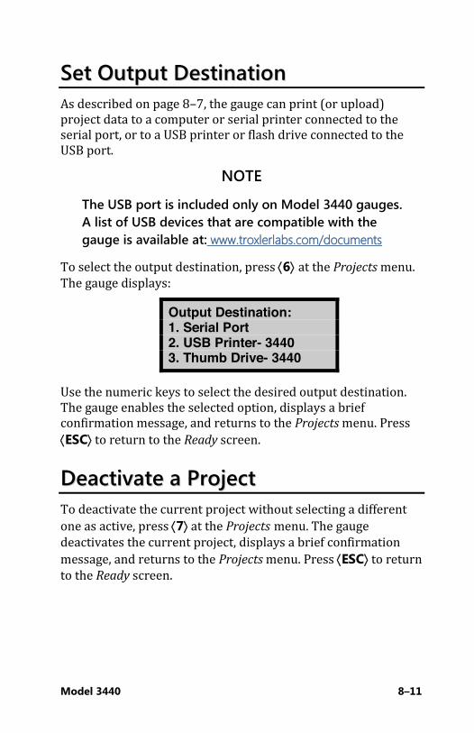
Model 3440 8–11
SSeett OOuuttppuutt DDeessttiinnaattiioonn As described on page 8–7, the gauge can print (or upload) project data to a computer or serial printer connected to the serial port, or to a USB printer or flash drive connected to the USB port.
NOTE
The USB port is included only on Model 3440 gauges. A list of USB devices that are compatible with the gauge is available at: www.troxlerlabs.com/documents
To select the output destination, press ¢6² at the Projects menu. The gauge displays:
Output Destination: 1. Serial Port 2. USB Printer- 3440 3. Thumb Drive- 3440
Use the numeric keys to select the desired output destination. The gauge enables the selected option, displays a brief confirmation message, and returns to the Projects menu. Press ¢ESC² to return to the Ready screen.
DDeeaaccttiivvaattee aa PPrroojjeecctt To deactivate the current project without selecting a different one as active, press ¢7² at the Projects menu. The gauge deactivates the current project, displays a brief confirmation message, and returns to the Projects menu. Press ¢ESC² to return to the Ready screen.
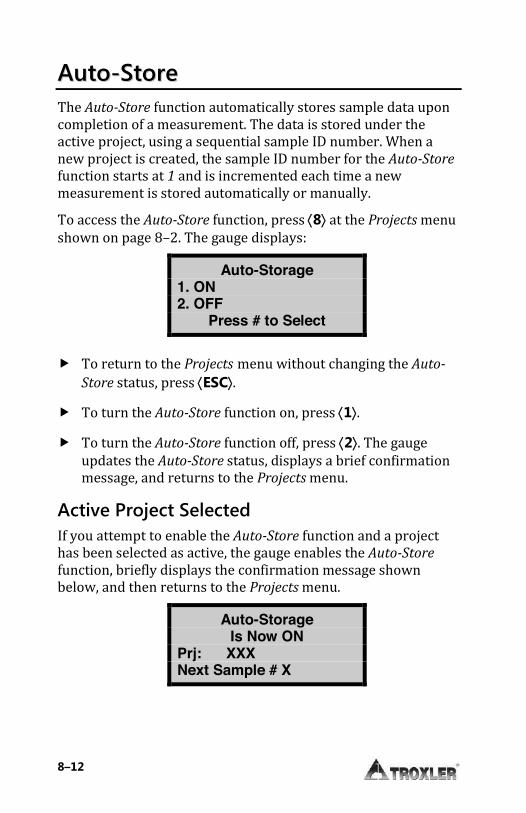
8–12
AAuuttoo--SSttoorree The Auto-Store function automatically stores sample data upon completion of a measurement. The data is stored under the active project, using a sequential sample ID number. When a new project is created, the sample ID number for the Auto-Store
function starts at 1 and is incremented each time a new measurement is stored automatically or manually. To access the Auto-Store function, press ¢8² at the Projects menu shown on page 8–2. The gauge displays:
Auto-Storage 1. ON 2. OFF
Press # to Select
f To return to the Projects menu without changing the Auto-
Store status, press ¢ESC².
f To turn the Auto-Store function on, press ¢1².
f To turn the Auto-Store function off, press ¢2². The gauge updates the Auto-Store status, displays a brief confirmation message, and returns to the Projects menu.
Active Project Selected If you attempt to enable the Auto-Store function and a project has been selected as active, the gauge enables the Auto-Store function, briefly displays the confirmation message shown below, and then returns to the Projects menu.
Auto-Storage Is Now ON
Prj: XXX Next Sample # X
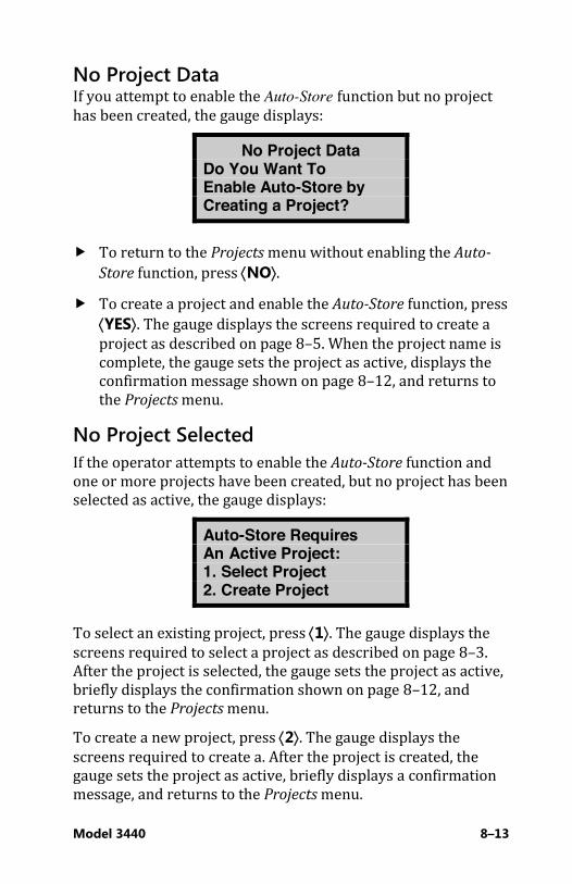
Model 3440 8–13
No Project Data If you attempt to enable the Auto-Store function but no project has been created, the gauge displays:
No Project Data Do You Want To Enable Auto-Store by Creating a Project?
f To return to the Projects menu without enabling the Auto-
Store function, press ¢NO². f To create a project and enable the Auto-Store function, press
¢YES². The gauge displays the screens required to create a project as described on page 8–5. When the project name is complete, the gauge sets the project as active, displays the confirmation message shown on page 8–12, and returns to the Projects menu.
No Project Selected If the operator attempts to enable the Auto-Store function and one or more projects have been created, but no project has been selected as active, the gauge displays:
Auto-Store Requires An Active Project: 1. Select Project 2. Create Project
To select an existing project, press ¢1². The gauge displays the screens required to select a project as described on page 8–3. After the project is selected, the gauge sets the project as active, briefly displays the confirmation shown on page 8–12, and returns to the Projects menu. To create a new project, press ¢2². The gauge displays the screens required to create a. After the project is created, the gauge sets the project as active, briefly displays a confirmation message, and returns to the Projects menu.

8–14
MMaannuuaall SSttoorree After completing a measurement and before taking another one, sample data can be stored manually under the active project. Refer to pages 8–3 through 8–5 for instructions on creating and selecting the active project. To manually store measurement data, press the ¢STORE² key while data is being displayed. If no project is active when the ¢STORE² key is pressed, the gauge displays the error message No active project!, then returns to the Ready screen.
NOTE
The ¢STORE² key is active only when measurement data is displayed. Measurement data is displayed at the end of a reading, or the most recent test results can be displayed using the ¢RECALL² key (see page 4–31).
For each measurement, the gauge can store a location description of up to 12 characters, as well as a note of up to 15 characters. For an Asphalt mode measurement, the gauge can also store the location with respect to the centerline (left, right, or neither), and the distance from the centerline. Follow the prompts to enter location information and/or a note.
Model 3440 9–1
CChhaapptteerr 99:: EExxtteennddeedd MMeennuu
This chapter covers the following topics and tasks:
9 Setting the date and time 9 Setting a user ID and customer name 9 Viewing source decay information 9 Erasing standard counts 9 Setting the Low Battery Warning display options 9 Resetting the software

9–2
EExxtteennddeedd MMeennuu To access the Extended menu, press ¢SETUP² to display the Setup menu, then press ¢.² ¢9². The gauge requests an access code:
Input Access Code _
Press <ENTER> Enter the access code shown on page xiv and press the ¢ENTER/START² key. The gauge displays the Extended menu:
-Extended- ↨ 1. Clock/Calendar 2. User ID 3. Customer Name
-Extended- ↨ 4. Language 5. Source Decay 6. Erase Stnd. Cnt.
-Extended- ↨ 7. Low Batt Warning 8. Software Reset 9. Test Menu
Use the up and down arrows to scroll between the menu options. To select a menu option, press the corresponding numeric key. To return to the Setup menu, press the ¢ESC² key.
Model 3440 9–3
CClloocckk//CCaalleennddaarr The Clock/Calendar function allows the operator to change the date and time, and to select the display format for each. This function is described on page 3–10.
UUsseerr IIDD The gauge can store a three-character user ID with each measurement. To enter or change the user ID, refer to page 3–13.
CCuussttoommeerr NNaammee The gauge can store a customer name of up to 12 characters. To enter or change the customer name, refer to page 3–13.

9–4
LLaanngguuaaggee The language feature is an optional upgrade (see page 5–16). If your gauge is enabled with this option, you can access the language function by pressing ¢3² at the Extended menu. The gauge displays:
-Language- ↨ 1. English 2. Espanole 3. Deutsch
-Language- ↨ 4. Francaise
Use the up and down arrows to scroll between the menu options. To select the desired language, press the corresponding number key. To return to the Extended menu, press the ¢ENTER/START² or ¢ESC² key.
SSoouurrccee DDeeccaayy The strength of radioactive material is measured by its activity, or rate of decay. This activity decreases with time. The length of time it takes a given amount of radioactive material to decay to half of its original strength is referred to as the half-life. The half-life of the Am-241:Be source is 432 years. The half-life of the Cs-137 source is 30 years. The Source Decay function allows the operator to view how the decrease in the radiation intensity of the source affects gauge density measurements. It displays the actual density standard count, the predicted standard count, and the percent difference between the two sets of counts. The gauge calculates the predicted standard count based upon the density standard
Model 3440 9–5
count at the time the gauge was calibrated and the number of days that have elapsed since calibration. To access the Source Decay function, press ¢5² at the Extended menu. The gauge displays:
Standard After Decay Current: ### Predicted: ### %Diff: ###
To return to the Extended menu, press the ¢ENTER/START² or ¢ESC² key.
EErraassee SSttaannddaarrdd CCoouunnttss The Erase Standard Counts function allows the operator or service technician to remove all (four) standard counts from gauge memory. To execute the Erase Standard Counts function, press ¢6² at the Extended menu. The gauge displays:
Erase Standard Storage Bank
<YES> or <NO>
f To return to the Extended menu without erasing the standard counts stored in memory, press ¢NO².
f To erase all the standard counts, press ¢YES². The gauge erases the standard counts stored in memory and returns to the Extended menu.

9–6
LLooww BBaatttteerryy WWaarrnniinngg The gauge constantly monitors the voltage and charge status of the NiMH batteries. The Battery Status function enables the operator to view the status of the NiMH batteries. In addition, if the battery voltage falls below a pre-determined threshold, the gauge displays a low-battery warning symbol (�) in the upper right corner of the Ready display. By default (Normal setting), the low-battery warning is displayed when the battery voltage falls below 6.2 V dc. At that point, the gauge has approximately three hours of battery operating life left, or less if the backlight is used. If the gauge is equipped with a GPS, the remaining battery operating life will be approximately one hour. The Low Battery Warning function enables the operator to select how early or late the low-battery warning is displayed. An early setting provides more time between when the warning is displayed and when the gauge shuts down. A later setting provides less warning time. To access this function, press ¢7² at the Extended menu. The gauge displays:
-Low Batt Warning- ↨ 1. Earliest 2. Early 3. Normal
-Low Batt Warning- ↨ 4. Later 5. Latest

Model 3440 9–7
Use the up and down arrows to scroll between the menu options. To select the desired low battery warning option, press the corresponding numeric key. To return to the Extended menu, press the ¢ESC² key.
SSooffttwwaarree RReesseett The Software Reset function sets selected user setup values (count time, measurement units, depth mode, user ID, customer name, etc.) to their factory default values.
NOTE
The Software Reset function does not affect the calibration constants, gauge serial number, clock and calendar settings, or projects stored in the gauge memory.
To access this function, press ¢7² at the Extended menu. The gauge displays:
System Reset Sets System Variables to Defaults! Continue?
<YES> or <NO>
f To return to the Extended menu without resetting system variables, press ¢NO².
f To reset system variables to default values, press ¢YES². The gauge resets the system variables and returns to the Extended menu.
TTeesstt MMeennuu NOTE
The functions available from the Test Menu are to be used by qualified service personnel only!

Model 3440 Appendix A–1
AAppppeennddiixx AA:: MMaaiinntteennaannccee && TTrroouubblleesshhoooottiinngg
This appendix covers the following topics and tasks:
9 Troubleshooting and error messages 9 Changing the display contrast 9 Maintaining and servicing your gauge 9 Charging and replacing the battery 9 Replacement parts list 9 Cleaning the gauge 9 Lubricating the source rod 9 Replacing the gasket and O-Ring 9 Returning the gauge for service

Appendix A–2
TTrroouubblleesshhoooottiinngg
Gauge Fails Standard Counts 11.. Ensure that the source rod opening on the gauge bottom is
completely closed or covered by the tungsten sliding block. If any opening is visible, the sliding block should be cleaned by the Radiation Safety Officer as described in Appendix D. If the sliding block still does not close completely, contact the nearest Troxler Service Center.
22.. Ensure that the guidelines for performing the standard count listed on page 4–16 are followed.
33.. Perform the standard count again. If it still fails, contact your nearest Troxler service center or representative.
No Density Readings The most likely reason for no density readings is an electronic problem, such as a failure of the detector preamplifier.
CAUTION
Also, the gauge may have gotten wet. The Model 3440 and 3440 gauges are not waterproof and should not be used in the rain. If the gauge gets wet make sure it is completely dry before sealing it in the case for storage. If you suspect that moisture may be inside the gauge open the keypad panel and run a fan or hairdryer (on low) in the gauge for 15 minutes to an hour in a clean environment. .
As a precaution, ensure that the tip of the source rod is intact and undamaged. Use a radiation survey meter to check the radiation levels at the surface of the gauge base where the source rod exits (without extending the source rod). A maximum reading of 10-20 mrem/hr is normal, and indicates the source is present. If the maximum reading is less than 1 mrem/hr or if a survey meter is not available, perform a visual
Model 3440 Appendix A–3
inspection of the source rod tip as follows to confirm its integrity. Extend the source rod just far enough to see the source rod tip. The tip should appear flat to slightly rounded and smooth. Complete the inspection as quickly as possible and stay at least 1 meter from the rod tip to minimize exposure (the dose rate at 1 meter from the unshielded source is about 2.7 mrem/hr). If the visual inspection indicates that the source rod tip is broken off (source is missing): 11.. Immediately contact your Radiation Safety Officer (RSO). 22.. Initiate a search for the source starting at the location where
the gauge was last used. 33.. Report lost or missing radioactive sources to your state or
federal radiation control agency in accordance with applicable regulatory requirements.
44.. Contact the Troxler Radiation Safety Department for further advice.
Gauge Readings Appear Erratic 11.. Ensure that the source rod is properly positioned in the
desired measurement position. For backscatter readings, do not allow the source rod to contact the material.
22.. Erratic density readings may be caused by a dirty sliding block. Clean the sliding block as instructed on page D-10 and then take readings again.
33.. Check the inside of the gauge for moisture. To dry the gauge interior, remove the keypad. If necessary, use a hair dryer (on low heat) to circulate warm air for 15 minutes to 1 hour.
44.. Remove any foreign objects from inside the gauge. 55.. Ensure the hardware mounting screws are tight and in
place. 66.. Check count time – a four-minute count will give the highest
precision with a repeatability of r1 pcf.
Appendix A–4
77.. Perform a statistical stability (stat) test. f If test passes, proceed with job. f If test fails, repeat two more times. If test fails two out of
three times, contact the nearest Troxler Service Center.
NOTE
To aid in verifying gauge readings, after a gauge has been calibrated, mark a test area on a concrete floor, sidewalk, or equivalent and measure the density (WD). This measurement can then be used as a reference to verify later gauge readings.
Unreadable, XXXX or ++++ is Displayed 11.. Check the standard counts in memory. If the standard
counts are suspect, perform new standard counts. If counts equal zero for both systems, replace high voltage board. Contact the nearest Troxler Service.
22.. Ensure that the measurement depth (depth of the source rod handle) is the same as the depth displayed on the display before starting a measurement.
33.. Check gauge for water damage. If the gauge is wet, dry the gauge interior with hairdryer (on low heat) for 15 minutes to 1 hour.
44.. Check that the calibration constants are valid. 55.. If necessary, perform a statistical stability (stat) test, record
the results and contact the nearest Troxler Service Center. Gauge Turns off after it is Turned On 11.. The gauge automatically turns off after five hours if no keys
are pressed. Try to turn the gauge on again. 22.. The gauge may be wet. Do not turn the gauge on until
moisture is removed from gauge interior! Component damage may result.
33.. If the battery is below 5.5 volts, recharge or replace the batteries.
Model 3440 Appendix A–5
44.. The front panel assembly may be defective. To test, replace the suspect front panel assembly with a good front panel assembly.
Short Battery Life after Recharging 11.. Check that you are using the correct charger. 22.. Ensure the charging indicator light (red LED) is illuminated
when the gauge is plugged in. 33.. NiMH batteries may be charged up to 500 full charge-
discharge cycles. The batteries may be reaching end of life cycle - replace.
CAUTION
All information stored in the gauge except the calibration constants and the chosen language is lost when the batteries are disconnected.
44.. Remove any loose screws or foreign objects from the gauge interior that may cause an electrical short to ground.
55.. The AC charger may be defective. Check voltage output of charge with a voltmeter, or use the dc charger to charge the batteries.
Satisfactory Counts, but Results are in Error i Ensure that the handle is seated in bottom of notch. i Ensure the measurement depth on the display screen
corresponds to the actual source rod handle depth. i Check to see if an offset (density, moisture, trench or
special) is enabled. i Ensure that the standard counts are correct. i Check calibration constants.
Appendix A–6
Possible Malfunction Indicators
Symptom Possible Malfunction
Batteries discharge prematurely HV Board Batteries do not charge CPU Board,
Preamp Board Battery low indicator does not function correctly
CPU Board
Beeper stops (or is erratic) CPU Board Display malfunctions CPU Board Display test Fails CPU Board Fails stability or drift tests Preamp board Gauge does not turn on when charger is connected
CPU Board
Gauge doesn't turn off CPU Board Gauge fails stat or drift tests HV Board Gauge fails tube test Preamp board Moisture or density counts are unstable
HV Board
No keypad response CPU Board No moisture or density counts Preamp Board,
HV Board

Model 3440 Appendix A–7
Error Messages The following table displays a list of the gauge error messages, as well as the possible causes and recommended solutions for each message.
Table 3. Error Messages
Error Message Possible Causes Solution
Bad Checksum! Default Settings Restored
Gauge settings and/or project data stored in memory have been corrupted and default (factory) settings have been restored.
Set up user preferences (such as measurement mode, count time, and so on) as described in Chapter 3.
Cannot Close File after Writing.
An error occurred when attempting to store data to a USB flash drive.
Try to store the data again. If error recurs, try a different USB flash drive.
Cannot Initialize Media
An error occurred when trying to access the USB flash drive.
Check that the USB flash drive is installed properly. If error recurs, try a different USB flash drive.
Cannot Open Printer
An error occurred when trying to communicate with a USB printer.
Check that the printer is powered on and is properly connected to the USB port. Ensure that the printer is compatible with the gauge. A list of compatible USB devices is available at: www.troxlerlabs.com/products
Cannot Write to the File
An error occurred when attempting to store data to a USB flash drive.
Try to store the data again. If error recurs, try a different USB flash drive.
Cannot Write to the Printer
An error occurred when trying to communicate with a USB printer.
Check that the printer is powered on and is properly connected to the USB port. Ensure that the printer is compatible with the gauge. A list of compatible USB devices is available at:

Appendix A–8
www.troxlerlabs.com/documents
Depth Sensor Error. Enable Manual Mode
A hardware problem has occurred with the depth strip.
To continue using the gauge, enable Manual depth mode. Contact the nearest Troxler Service Center.
Error Writing to the File
An error occurred when attempting to store data to a USB flash drive.
Try to store the data again. If error recurs, try a different USB flash drive.
Error! Stat Test Not Valid
Operator has tried to run a drift test without having a valid stat test.
Perform a stat test, and then run a drift test.
Gauge Requires Re-calibration! Contact Tech Support
The calibration constants stored in the gauge have become corrupted.
Contact the nearest Troxler Service Center.
Gmb Target Exceeds Limits!
The target value must be between 20.0 and 200.0 pcf. The operator has entered a value outside this range.
Enter a target value between 20.0 and 200.0 pcf.
Gmm Target Exceeds Limits!
The target value must be between 20.0 and 200.0 pcf. The operator has entered a value outside this range.
Enter a target value between 20.0 and 200.0 pcf.
Invalid Access Code
Operator entered an invalid access code.
Enter the correct access code (see the front of this manual).
Invalid Depth The source rod is not at a valid depth when starting a measurement.
Ensure the source rod position is at a valid depth when starting a measurement. Contact the nearest Troxler Service Center.
Low Battery. Gauge Shutting Down. Turn off & Charge
The following three items are all true: the charger is not connected, the NiMH batteries are low, and
Charge the NiMH batteries and replace the alkaline batteries.

Model 3440 Appendix A–9
the alkaline batteries need replacing.
Moisture Offset Exceeds Limits!
The moisture offset (k) value must be between –200 and 200. When performing a moisture offset, the resulting k value was outside of these limits.
Enter a new moisture offset.
No active project! Operator tried to store measurement data, but no project is active.
Select an existing project or create a new project and select as active.
Proctor Target Exceeds Limits!
The target value must be between 20.0 and 200.0 pcf. The operator has entered a value outside this range.
Enter a target value between 20.0 and 200.0 pcf.
Project has No Data!
Operator attempted to view a project with no data.
Select the correct project when attempting to view.
Overlay Thickness Exceeds Limits!
When using the Nomograph function, the overlay thickness value must be between 0 and 10 in. The operator has entered a value outside this range.
Enter an overlay thickness value between 0 and 10 in.
Warning!! Time to Reach Precision too high
When using the Precision function, the time required to reach the selected precision value exceeds 60 minutes.
Enter a different precision value or disable the Precision function.

Appendix A–10
DDiissppllaayy CCoonnttrraasstt The gauge display may be difficult to read when viewed in bright light. If so, adjust the display contrast as follows: 11.. Loosen the four captive screws located in the corners of the
keypad. 22.. Gently lift the control unit from the gauge and tilt it forward. 33.. As shown in the image below, an adjustment potentiometer
for the display contrast is located inside an access hole in the back panel of the control unit.
44.. Using a small screwdriver, adjust the potentiometer to obtain the desired display contrast.
55.. Gently place the control unit inside the gauge and tighten the four captive screws in the corners of the keypad.
Figure 12. Adjusting the Display Contrast
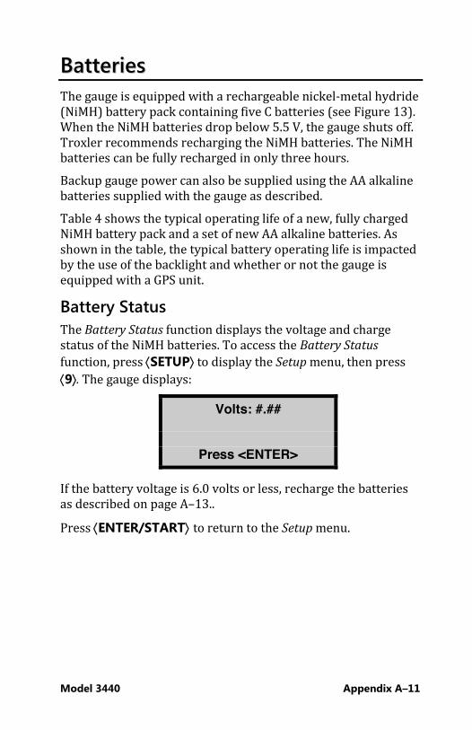
Model 3440 Appendix A–11
BBaatttteerriieess The gauge is equipped with a rechargeable nickel-metal hydride (NiMH) battery pack containing five C batteries (see Figure 13). When the NiMH batteries drop below 5.5 V, the gauge shuts off. Troxler recommends recharging the NiMH batteries. The NiMH batteries can be fully recharged in only three hours. Backup gauge power can also be supplied using the AA alkaline batteries supplied with the gauge as described. Table 4 shows the typical operating life of a new, fully charged NiMH battery pack and a set of new AA alkaline batteries. As shown in the table, the typical battery operating life is impacted by the use of the backlight and whether or not the gauge is equipped with a GPS unit.
Battery Status The Battery Status function displays the voltage and charge status of the NiMH batteries. To access the Battery Status function, press ¢SETUP² to display the Setup menu, then press ¢9². The gauge displays:
Volts: #.##
Press <ENTER>
If the battery voltage is 6.0 volts or less, recharge the batteries as described on page A–13.. Press ¢ENTER/START² to return to the Setup menu.
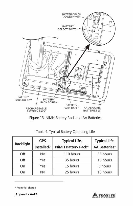
Appendix A–12
BATTERY PACKCONNECTOR
BATTERYSELECT SWITCH
AA ALKALINEBATTERIES (5)
BATTERYPACK SCREW
BATTERYPACK CABLE
BATTERYPACK SCREW
RECHARGEABLEBATTERY PACK
Figure 13. NiMH Battery Pack and AA Batteries
Table 4. Typical Battery Operating Life
Backlight GPS
Installed?
Typical Life,
NiMH Battery Pack*
Typical Life,
AA Batteries*
Off No 110 hours 55 hours Off Yes 35 hours 18 hours On Yes 15 hours 8 hours On No 25 hours 13 hours
* From full charge
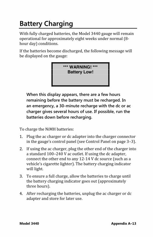
Model 3440 Appendix A–13
BBaatttteerryy CChhaarrggiinngg With fully charged batteries, the Model 3440 gauge will remain operational for approximately eight weeks under normal (8-hour day) conditions. If the batteries become discharged, the following message will be displayed on the gauge:
*** WARNING! *** Battery Low!
When this display appears, there are a few hours remaining before the battery must be recharged. In an emergency, a 30-minute recharge with the dc or ac charger gives several hours of use. If possible, run the batteries down before recharging.
To charge the NiMH batteries: 11.. Plug the ac charger or dc adapter into the charger connector
in the gauge’s control panel (see Control Panel on page 3–3). 22.. If using the ac charger, plug the other end of the charger into
a standard 100–240 V ac outlet. If using the dc adapter, connect the other end to any 12-14 V dc source (such as a vehicle's cigarette lighter). The battery charging indicator will light.
33.. To ensure a full charge, allow the batteries to charge until the battery charging indicator goes out (approximately three hours).
44.. After recharging the batteries, unplug the ac charger or dc adapter and store for later use.

Appendix A–14
NOTE
The battery select switch must be in the RECHARGEABLE position to charge the NiMH batteries.
Replacing the NiMH Battery Pack To replace the NiMH battery pack (P/N 110374): 11.. Turn the gauge off. 22.. Using a 7/64-inch Allen wrench, remove the six screws that
hold the top shell to the gauge base. 33.. Clean the screws and set them aside. 44.. Carefully remove the gauge top shell and slide it up, out of
the way. To keep the top shell out of the way, tie it to the handle.
55.. Unplug the battery cable from the battery connection on the top circuit board. Gently squeeze the connector to disconnect.
66.. Remove the two battery pack screws and set them aside. 77.. Remove the old NiMH battery pack and install the
replacement pack. 88.. Replace the two screws. 99.. Plug the battery cable into the battery connection on the top
circuit board. 1100.. Re-assemble the gauge top shell.
Model 3440 Appendix A–15
Installing and Using Alkaline Batteries If your Model 3440 gauge is installed with the alkaline battery backup, you can power the gauge using five AA alkaline batteries. To install the batteries: 11.. Turn the gauge off. 22.. Loosen the four captive screws on the control unit. 33.. Carefully lift the control unit from the gauge. 44.. Unplug the ribbon cable from the control unit by pushing
the levers on either side of the ribbon down. 55.. Install five standard AA alkaline batteries into the battery
holder. 66.. Set the battery select switch to the ALKALINE position. 77.. Plug the ribbon cable into the control unit. 88.. Attach the control unit to the gauge with the four captive
screws.

Appendix A–16
MMeecchhaanniiccaall MMaaiinntteennaannccee The following procedures should be performed to keep the Model 3440 gauge in good working order. If a serious problem with the gauge arises, contact the nearest Troxler Service Center or representative for instructions. For a list of Troxler and authorized Troxler service centers, refer to the front of this manual or visit the Troxler website at www.troxlerlabs.com
CAUTION
Personnel should wear a dosimeter to monitor radiation exposure while performing maintenance on the gauge if it is required by their radioactive materials license or local regulations.
CAUTION – EUROPEAN COUNTRIES
Do not separate the control unit from the base. Doing so will result in non-compliance with EMC directive. Call your Troxler representative for additional information.
Cleaning the Base and Topshell If the Model 3440 gauge is to provide precise and accurate measurements over a long period of time the gauge should be kept as clean as possible. Monitor the outside surfaces of the instrument for accumulations of dirt, oil, asphalt, or any other foreign matter. If a build-up of material is visible on the gauge base or topshell, use the following procedures for cleaning: To clean the gauge base, use a putty knife to scrape away any built-up accumulations of soil or asphalt. Be careful not to damage the gauge base! After removing any large accumulations, wipe the gauge base with a cloth soaked in BindOff, WD-40 or similar non-corrosive cleaner to remove the remaining debris.
Model 3440 Appendix A–17
CAUTION
Cleaners and lubricants can damage the keypad. Do not allow these chemicals to make contact with the keypad!
Currently, the Model 3440 gauge topshell is manufactured from an engineering thermoplastic designed specifically to provide high impact strength and to offer excellent compatibility with many industrial solvents and petrochemicals. The topshell may be cleaned with mild (low alkaline) soap and water. Other approved cleaning substances include methyl, isopropyl, or isobutyl alcohols.
CAUTION
The use of any unapproved cleaning agents such as methyl-ethyl-ketones, amines, and methylene chloride will damage the topshell and void the warranty.
Source Rod Lubrication If the source rod does not slide up and down freely, the source rod bearing may require cleaning and lubrication. 11.. Remove the control panel assembly from the gauge by
loosening the four captive screws that secure it to the topshell. Lift the control unit and disconnect the ribbon cable. Set control unit aside.
22.. Locate the grease fitting at the base of the source rod tower.
NOTE
The vent valve was not installed on earlier gauges. Instead, an Allen-head screw was located beneath the grease fitting. On the gauges, remove the Allen-head screw before applying lubricant to allow the old grease to be ejected. Failure to remove the Allen screw may result in severe mechanical damage to the base assembly.

Appendix A–18
33.. Using a standard 16-ounce grease gun loaded with a Magnalube-G cartridge, apply five shots of lubricant or enough to eject all dirty grease until clean grease is visible.
44.. Re-assemble the gauge. Do not apply more than 6 in-lb. torque to the topshell screws.
Lubricating the Source Rod If the source rod does not slide up and down freely, the source rod bearing may require lubrication. A grease fitting is located beneath the top shell at the base of the source rod tower. 11.. Remove the control unit from the gauge by loosening the
four captive screws that secure the control unit to the top shell. Lift the control unit out of the gauge and disconnect the ribbon cable.
22.. Locate the grease fitting at the bottom of the source rod tower.
33.. Using a standard 16-oz grease gun loaded with a Magnalube�-G cartridge, apply five shots of lubricant to the grease fitting.
44.. Re-assemble the control unit.
Gasket Replacement Four gaskets seal the gauge from moisture, dirt, and debris. Condensation may form inside the gauge if the gauge has been out in extremely wet weather or in high humidity, or if it is used in the heat and stored in an air conditioned building. In this case, remove the topshell and allow the gauge to dry. If necessary, use a hairdryer (on low heat) to remove any built-up moisture. If moisture continues to be a problem or debris is present inside the gauge base, the gaskets may need replacing. To replace the control panel gasket (P/N 110841), loosen the four screws in the corners of the panel, and remove the panel from the gauge topshell. Use care in removing the panel and disconnecting the ribbon cable. Gently peel the old gasket from the panel and replace with a new gasket. Reconnect the ribbon cable and replace the control panel.
Model 3440 Appendix A–19
To replace the two post gaskets and the topshell gasket, remove the screws that hold the topshell to the gauge base. Remove the screws from the metal triangle around the base of the triangle extrusion and raise this piece. Then lift the topshell from the base. Gently peel the gaskets away from the topshell and gauge base and replace. Tighten topshell screws to 6 in-lb. If replacing the post gaskets, slide up and over the source rod handle. A light coating of talcum powder on the inside of the new post gasket will aid in reassembly.
Replacing Gasket and O-Ring The gauge uses a gasket and O-rings to protect its electronics from moisture, dirt, and debris. However, if the gauge has been exposed to extremely wet weather or high humidity, or if the gauge was used in the cold and stored in a warm building, condensation may form inside the gauge. If this happens, remove the control unit to allow the gauge to dry. Use a hair dryer (on low heat) if necessary to remove any built-up moisture. If moisture continues to be a problem or debris is present inside the gauge base, the control panel gasket or top shell O-ring may need replacing. To replace the control panel gasket (P/N 110841), loosen the four captive screws that attach the control unit (keypad) to the top shell. Carefully lift the control unit from the top shell and detach the ribbon cable. Gently peel the old gasket from the panel and replace it with a new gasket. Reconnect the ribbon cable and reinstall the control unit. To replace the top shell O-ring (P/N 110899), remove the six screws that hold the top shell to the gauge base. Lift the top shell from the gauge base to expose the O-ring. Peel the old O-ring from the groove in the gauge base. Place the replacement O-ring in the groove, and run your finger around its circumference to ensure it is properly seated in the groove. If the O-ring is too long, cut it to length, ensuring that the two ends butt against each other. Reassemble the top shell to the base.

Appendix A–20
RReeppllaacceemmeenntt PPaarrttss This section provides a list for replacing the major parts of the gauge and purchasing accessories. Many parts can be ordered from our e-commerce site at www.troxlerlabs.com.
PART NO. DESCRIPTION
110821 3440 Gauge Topshell O-ring/Gasket
110013 3440 Bottomplate
110016 3440 Battery Assembly (with case)
110821 3440 Topshell
110848.0040 3440 Nameplate
007158 O-ring for Triangle Tower
Maintenance Supplies PART NO. DESCRIPTION
012784 Lubricant, Magnalube-G paste 1.5 oz. tube
012786 Lubricant, Magnalube-G paste 1 lb. can
012789 Lubricant, Magnalube-G 14.5 oz.
100761 Source rod pig
018141 BindOff (1 gallon)
Accessories PART NO. DESCRIPTION
110017 3440P/3440 Shipping Case
100421 Drill Rod
102111 Scraper Plate

Model 3440 Appendix A–21
103680.1000 Extraction Tool
110403 AC Adapter, 12 V CE
110867 AC Adapter, International, 6 pc
104156 DC Charger
110991 3440 Operator’s Manual
113128 RS-232 Cable
102876.0005 Leak Test Kit (4 units)
109661 TroxAlert Survey Meter
104661.4000 Printer Package
107480 Concrete Adapter
021140 Radiation Sign Kit
109661 TroxAlert Survey Meter with beeper
105817 Emergency Response Kit
104661.4000 Printer Package
Appendix A–22
RReettuurrnniinngg tthhee GGaauuggee ffoorr SSeerrvviiccee All shipments within the United States to the factory must be accompanied by an RGA (Returned Goods Authorization) number, and a description of the instrument and its problem. Send a completed RGA form, found on the Downloads page at www.troxlerlabs.com, with each item returned for service. This information is used by Troxler shipping and service personnel to expedite the repair work. To obtain an RGA number, please call or fax the factory or branch office with your request. Please have the following information available when contacting Troxler for an RGA number: i Is the gauge still under warranty? i Model and Serial number i Will estimate be required before performing any work on
the gauge? i Problem or difficulty you are having with the instrument. i Shipment method to Troxler and for return shipment. i Shipping and billing address (not P.O. Box): street address
and zip code. i Telephone number and contact (for questions from Troxler). i Payment method: credit card, account number, or purchase
order number. All U.S. government agencies (city, county, state and federal) must send purchase orders.

Model 3440 B–1
AAppppeennddiixx BB:: SSppeecciiffiiccaattiioonnss
This appendix provides the measurement specifications for Model 3440 gauges.

B–2
MMeeaassuurreemmeenntt SSppeecciiffiiccaattiioonnss
Density at 2000 kg/m3 Direct Transmission (150 mm)
.25 min 1 min 4 min
Precision (kg/m3) r6.8 r3.40 r1.70 Composition error (kg/m3) r20.0 r20.0 r20.0 Surface error (kg/m3) (100% Void)
–17.0 –17.0 –17.0
Backscatter (98%, 100 mm)
.25 min 1 min 4 min
Precision (kg/m3) r16.0 r8.00 r4.00 Composition error (kg/m3) r40.0 r40.0 r40.0 Surface error (kg/m3) (100% Void)
–75.0 –75.0 –75.0
Moisture at 240 kg/m3 .25 min 1 min 4 min
Precision (kg/m3) r10.3 r5.1 r2.6 Surface error (kg/m3) (1.25 mm, 100% void, kg/m3)
–18.0 –18.0 –18.0
Precision is defined as rone (1) standard deviation in density readings. This number is calculated by the ratio of the standard deviation in the counting rate and the slope of the calibration curve at a given density.

Model 3440 B–3
U.S. Customary Units Density at 125 PCF Direct Transmission (6 inches)
.25 min 1 min 4 min
Precision (pcf) r0.42 r0.21 r0.11 Composition error (pcf) r1.25 r1.25 r1.25 Surface error (pcf) (100% Void)
–1.06 –1.06 –1.06
Backscatter (98%, 4 inches)
.25 min 1 min 4 min
Precision (pcf) r1.00 r0.50 r0.25 Composition error (pcf) r2.50 r2.50 r2.50
Surface error (pcf) (100% Void)
–4.68 –4.68 –4.68
Moisture at 15 PCF .25 min 1 min 4 min
Precision (pcf) r0.64 r0.32 r0.16 Surface error (pcf) (0.05 in., 100% void, pcf)
–1.12 –1.12 –1.12

B–4
RRaaddiioollooggiiccaall SSppeecciiffiiccaattiioonnss Gamma Source 0.30 GBq (8 mCi) r 10%
Cs-137 Neutron Source 1.48 GBq (40 mCi) r 10%
Am-241:Be Source Type Sealed Source – Special
Form Source Housing Stainless Steel,
Encapsulated
Shielding Lead, Tungsten
Surface Dose Rate See Radiation Profile on page D-17
Shipping Case Type A, Yellow II, TI = 0.3
EElleeccttrriiccaall SSppeecciiffiiccaattiioonnss Stored Power 4 ampere hours
Average Current Consumption
Normal 35 mA With backlight on 140 mA With GPS on 105 mA With backlight and GPS on 210 mA Time Before Automatic Shutdown
5 hours of complete inactivity
Power Source(s): Main 5 C NiMH (Rechargeable

Model 3440 B–5
Pack) batteries Backup (optional)
5 AA alkaline batteries
Charge Source
12 V dc, 2A
Battery Recharge Time
3 hours maximum, automatic cutoff (may be charged incrementally without damaging the batteries)
Liquid Crystal Display
Alphanumeric, 4 line u 20 character, backlit
Keypad
30-key sealed membrane
Serial Data Format
9600 baud 1 stop bit No parity 8 data bits Xon-Xoff flow control
Gauge-to-PC Computer Cable (Null Modem Serial Cable, P/N 113128)
9 pin FEMALE 9 pin FEMALE
Rx (pin 2) Tx (pin 3)
Tx (pin 3) Rx (pin 2)
Gnd (pin 5) Gnd (pin 5)
USB Port (optional) A list of compatible USB devices is available at www.troxlerlabs.com/documents
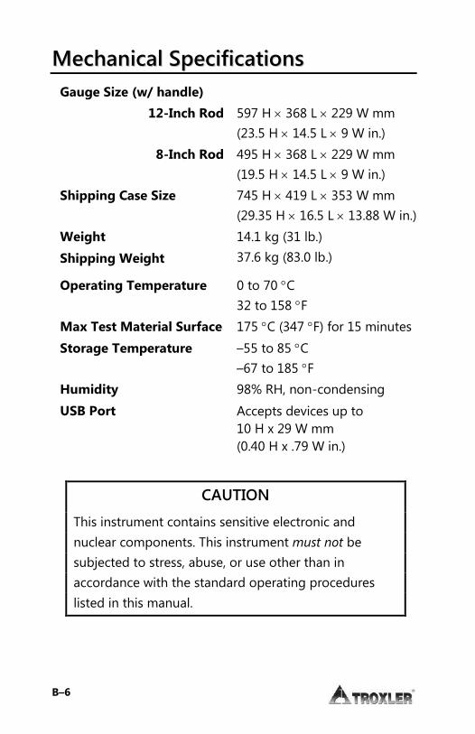
B–6
MMeecchhaanniiccaall SSppeecciiffiiccaattiioonnss Gauge Size (w/ handle)
12-Inch Rod 597 H u 368 L u 229 W mm (23.5 H u 14.5 L u 9 W in.)
8-Inch Rod 495 H u 368 L u 229 W mm (19.5 H u 14.5 L u 9 W in.)
Shipping Case Size 745 H u 419 L u 353 W mm (29.35 H u 16.5 L u 13.88 W in.)
Weight 14.1 kg (31 lb.)
Shipping Weight 37.6 kg (83.0 lb.)
Operating Temperature 0 to 70 qC 32 to 158 qF
Max Test Material Surface 175 qC (347 qF) for 15 minutes
Storage Temperature –55 to 85 qC –67 to 185 qF
Humidity 98% RH, non-condensing
USB Port Accepts devices up to 10 H x 29 W mm (0.40 H x .79 W in.)
CAUTION
This instrument contains sensitive electronic and nuclear components. This instrument must not be subjected to stress, abuse, or use other than in accordance with the standard operating procedures listed in this manual.

Model 3440 C–1
AAppppeennddiixx CC:: TTrraannssppoorrttiinngg && SShhiippppiinngg
Devices containing radioactive materials must be transported in accordance with the rules of the U.S. Department of Transportation (DOT) and the International Atomic Energy Agency (IAEA).
The IAEA recommendations have been codified in the International Air Transport Association (IATA) Dangerous Goods Regulations. International customers should consult their local government or licensing authority for applicable regulations.

C–2
UU..SS.. SShhiippppiinngg RReeqquuiirreemmeennttss The U.S. DOT hazmat regulations (49 CFR, Parts 100–185) apply any time a nuclear device is transported by motor vehicle on a public highway or by other means of transport (rail, air, ship). The major requirements for transporting a nuclear gauge in the United States are listed below. For more detailed information about these requirements, please refer to the Troxler
Transportation Guide. i A copy of the current IAEA Certificate of Competent
Authority for each source in the gauge (Special Form Certificate) must be kept on file. Current versions can be downloaded from the Troxler website, www.troxlerlabs.com.
i A copy of the results of the Type A package testing must be kept on file.
i Hazmat employee training records must be kept on file. i An Emergency Response Information document must be in
the vehicle and immediately accessible to the driver. i A properly completed bill of lading must be in the vehicle
and immediately accessible to the driver. The shipping papers must include a 24-hr emergency response phone number.
i If shipping by air, a Shipper's Declaration for Dangerous
Goods must accompany the air waybill. i The package must be properly marked and labeled in
accordance with hazmat regulations. i The package must have a tamper-evident seal. i The package must be inspected prior to each shipment. i The package must be securely blocked and braced in the
vehicle to prevent shifting during transport.

Model 3440 C–3
Accident Notification Requirements In the event of a reportable incident involving radioactive material, notify the licensing agency as soon as practical. The operator is also required to notify, at the earliest practical moment, the U.S. DOT at 1-800-424-8802 of an accident that occurs during the course of transportation (including loading, unloading, and temporary storage) in which fire, breakage, spillage, or suspected contamination occurs involving shipment of radioactive materials.
Hazmat Training The U.S. DOT regulations require every hazmat employer to train, test, certify, and maintain records for each hazmat employee. Hazmat training applies to anyone who transports or prepares for transport radioactive materials. Refresher training is required every three years for shipment / transport by roadway in the US. Shipment by air requires training every 2 years under IATA Dangerous Goods regulations.

C–4
CCaannaaddiiaann SShhiippppiinngg RReeqquuiirreemmeennttss The Transportation of Dangerous Goods Act and Regulations (TDG) and Transport Packaging of Radioactive Materials
Regulations (TPRM) apply any time a nuclear device used in commerce is transported by any means in Canada. For training and accident notification requirements, consult the Transportation of Dangerous Goods Regulations. For further information on transporting a nuclear device, contact the transportation section of the Canadian Nuclear Safety Commission (CNSC).

Model 3440 D-1
AAppppeennddiixx DD:: RRaaddiiaattiioonn TThheeoorryy && SSaaffeettyy
This appendix is required reading for anyone who will operate the Model 3440 Surface Moisture-Density Gauges.
This appendix covers topics related to radiation theory and the safe operation of the gauge. A brief overview of the regulatory requirements related to the ownership and use of the gauge, as wel l as a listing of radiation safety-related warnings and cautions, is included.

D–2
RRaaddiiaattiioonn TThheeoorryy A more detailed discussion of radiological theory can be found in the Troxler Nuclear Gauge Safety Training Program manual, provided at the Troxler Safety Class.
Atomic Structure All matter is made up of atoms. For example, water has two atoms of hydrogen (H) and one atom of oxygen (O), which in chemical notation is written H2O. An atom is made up of a dense nucleus, consisting of positively charged protons and uncharged neutrons, surrounded by a cloud of negatively charged electrons. Under normal circumstances, the number of electrons in an atom equals the number of protons. The number of protons in the atom is called the atomic number (Z). A chemical element consists of all atoms having the same atomic number. The number of protons plus neutrons in the nucleus is called the atomic mass (A). Atoms of a given chemical element can exist in slightly different variants called isotopes that have different atomic masses. For example, carbon-12 (C-12) is non-radioactive and carbon-14 (C-14) is radioactive. Isotopes that are radioactive are termed radioisotopes or radionuclides. Figure 14 depicts a helium atom consisting of two protons and two neutrons in the nucleus and two orbiting electrons. ELECTRONS
NEUTRON PROTON
Figure 14. Diagram of an Atom

Model 3440 D-3
Radioactivity Radioactivity is the spontaneous transformation (or disintegration) of an unstable nucleus into a more stable configuration accompanied by the emission of radiation. The quantity of a radioactive material is measured in terms of the average number of nuclear disintegrations per unit time. The traditional unit of measure for radioactivity (or activity) is the curie (Ci), which is defined as 3.7 u 1010 disintegrations per second. The activities of the radioactive sources in nuclear gauges are so small that they are typically measured in millicuries (mCi), which is one-thousandth of a curie, or microcuries (PCi), which is one-millionth of a curie. In the Standard International (SI) (or metric) system, the unit of activity is the becquerel (Bq), which equals one disintegration per second. Because the becquerel is such an extremely small unit, the activity of sources in nuclear gauges is normally expressed in megabecquerel (MBq), which is one million becquerels, or gigabecquerel (GBq), which is one billion Bq. The radioactivity of a source is not constant, but decreases with time as the source decays. The time it takes for one-half of the original atoms to disintegrate is called the half-life. In successive half-lives, the activity decreases to 1/2, 1/4, 1/8 and so on of the initial value. After seven half-lives, less than 1% of the original radioactive atoms remain. Each radioisotope has a characteristic half-life, which can range from seconds to billions of years. The half-lives for the typical radioisotopes used in nuclear gauges are:
Radioisotope Half-life
Cs-137 30 years
Am-241 432 years

D–4
Types of Radiation The radioactive sources in the gauge produce four types of radiation:
Alpha particles Beta particles Gamma rays (photons) Neutrons
The alpha and beta particles are stopped by the source capsule. Therefore, they present no external hazard to personnel. Only the gamma and neutron radiation from sealed sources contribute to any occupational radiation exposure. Gamma rays (photons) are a type of electromagnetic radiation, like X rays, radio waves, and visible light. Photons have no mass or electrical charge, and travel at the speed of light. Gamma rays are energetic and penetrating. Dense materials (such as lead, tungsten, and so on) provide the best shielding against gamma radiation. Neutrons are a form of particulate radiation but, unlike alpha and beta particles, they have no electrical charge. This makes neutron radiation very penetrating. Fast neutrons lose energy primarily by so-called “billiard ball” elastic collisions with the nuclei of low atomic number atoms, especially hydrogen. The best shielding materials for fast neutrons are those with a high hydrogen content, such as water, concrete, and polyethylene.

Model 3440 D-5
RRaaddiiaattiioonn SSaaffeettyy This section discusses the principles of general radiation safety. This information includes specific procedures for operating, inspecting, cleaning, and leak testing the gauge to ensure safe operation.
Radiation Dose Radiation cannot be detected by any of the human senses (sight, touch, hearing, smell). However, using appropriate instruments and devices, radiation can be detected and measured at levels far below those that significantly affect health. For purposes of radiation protection, the basic unit of radiation dose is the rem. The SI unit is the sievert (Sv), where 1 Sv = 100 rem. The rem is a relatively large unit, so often radiation dose is expressed in smaller units called millirem (mrem), where 1 rem = 1000 mrem. The risk of injury from radiation is generally related to the total radiation dose received over a period of time. It is also related to the dose rate, which is the amount of dose received per unit time. The same amount of radiation received over a long period (months to years) is much less hazardous than if received over a very short period (hours). This has to do with the body’s ability to repair cell damage caused by the radiation. The U.S. Nuclear Regulatory Commission (NRC) has established the following limits on the amount of whole body radiation exposure that individuals may safely receive from licensed radioactive materials.
Type of Individual Dose Limit
Adult worker 5000 mrem per year
Minor (under 18 years old) 500 mrem per year
Member of the public 100 mrem per year
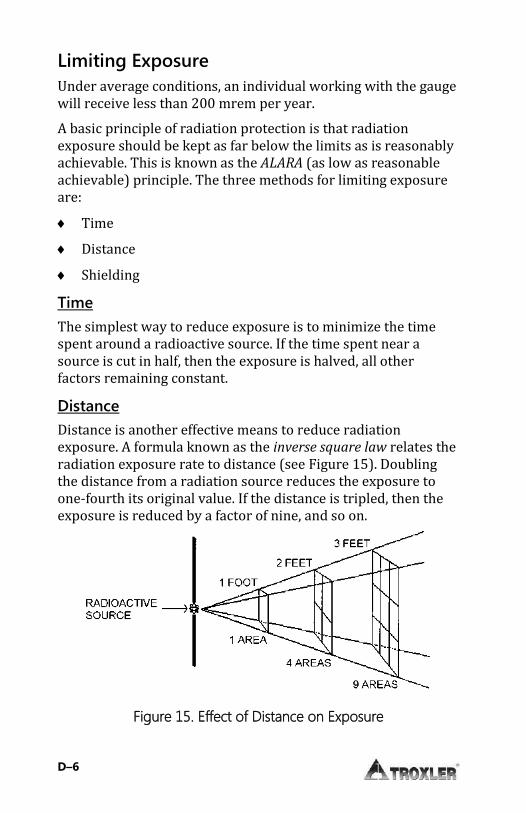
D–6
Limiting Exposure Under average conditions, an individual working with the gauge will receive less than 200 mrem per year. A basic principle of radiation protection is that radiation exposure should be kept as far below the limits as is reasonably achievable. This is known as the ALARA (as low as reasonable achievable) principle. The three methods for limiting exposure are: i Time i Distance i Shielding Time The simplest way to reduce exposure is to minimize the time spent around a radioactive source. If the time spent near a source is cut in half, then the exposure is halved, all other factors remaining constant. Distance Distance is another effective means to reduce radiation exposure. A formula known as the inverse square law relates the radiation exposure rate to distance (see Figure 15). Doubling the distance from a radiation source reduces the exposure to one-fourth its original value. If the distance is tripled, then the exposure is reduced by a factor of nine, and so on.
Figure 15. Effect of Distance on Exposure

Model 3440 D-7
Shielding Shielding is any material used to reduce the radiation exposure rate from a radioactive source. The gauge has some built-in shielding, which reduces the exposure rate. When gauges are in storage, additional shielding may be necessary to keep exposure to personnel in adjacent areas below the dose limits for members of the public. The thickness of any material that reduces the incident radiation intensity by one-half is known as the half-value layer
(HVL). The HVL of a material varies with the type and energy of radiation. The HVL values of certain common shielding materials are shown below for gamma and fast neutron radiation.
Material Cs-137 Gamma Half-Value Layer
Am-241:Be Neutrons Half-Value Layer
Concrete 1.9 in. 4.3 in.
Lead 0.3 in. †
Personnel Monitoring In the United States, anyone working with or near radioactive materials is subject to occupational dose limits. Individual monitoring of each authorized user is recommended in order to demonstrate compliance with these dose limits. The most common types of individual monitoring devices used by licensees are film badges and thermoluminescent dosimeter (TLD) badges. Film badges are typically exchanged and processed monthly due to concerns about film fading. TLD badges are usually exchanged quarterly. Troxler offers NVLAP-certified personnel monitoring services using TLD badges. In Canada, nuclear gauge users are not normally classified as Atomic Radiation Workers. In such cases, the general public
† Lead does not provide any effective shielding of fast neutrons.
D–8
dose limit of 500 mrem/year applies. Users may not be required to wear a dosimeter. To establish the personnel monitoring requirements for your application, consult the conditions of your radioisotope license and the CNSC regulatory document R91: Monitoring and Dose Recording for the Individual.
Source Encapsulation The neutron (americium-241:beryllium in the Model 3440 and photon (cesium-137) source materials are welded inside stainless steel capsules. These sealed sources meet U.S. and international regulatory requirements for classification as “Special Form” radioactive material for purposes of transportation. The sealed sources are designed to prevent leakage of radioactive material under severe accident conditions. They are also designed to comply with applicable ANSI classification requirements for sealed sources used in portable gauges.
Source Rod Inspection To ensure the integrity of the source rod, Troxler recommends that a qualified Troxler service person inspect the gauge and the source rod at least once every five years. This inspection includes checking for excessive wear, corrosion, or damage that could affect the safety of gauge operation. However, as a precaution if the gauge is ever damaged or dropped, ensure that the tip of the source rod is intact and undamaged (that is, ensure that the source is not missing) as described on page D-9. Contact the Troxler Radiation Safety Department for further advice.
Model 3440 D-9
Daily Inspection The gauge should be inspected daily before use to ensure proper operation of all safety features as follows: i The source rod opening in the bottom of the gauge is
equipped with a spring-loaded tungsten sliding block that shuts when the source rod is in the SAFE (shielded) position. To check the operation of the sliding block, push the source rod down into the backscatter position (see Figure on page 3–5), and then raise it back to the SAFE position. You should hear a click as the sliding block snaps shut. Turn the gauge over and verify that the sliding block is completely shut. If any portion of the opening is uncovered, the sliding block should be cleaned before using, transporting, or storing the gauge. Refer to page D–10 for instructions on cleaning the tungsten sliding block.
WARNING!
Do not store or transport the gauge unless the sliding block is closed. Increased radiation levels may cause excessive personnel radiation exposure and may violate transportation regulations.
If a radiation survey instrument is available, verify that the radioactive gamma source is in place by measuring the exposure rate at the surface of the gauge. The exposure rate should be approximately 10 – 20 mrem per hour. A reading of about 1 mrem or less indicates either that the survey instrument is not working properly or that the cesium-137 source may be missing. Refer to the Troubleshooting section of Appendix A for further instructions.

D–10
Cleaning the Tungsten Sliding Block If the tungsten sliding block is not kept clean, it may stick partially or completely open when the source rod is raised to the SAFE (shielded) position. This will result in high radiation levels near or in line with the source rod opening on the bottom of the gauge. After cleaning and reassembling the gauge as described below, check the operation of the sliding block by pushing the source rod into the backscatter position, then returning it to the SAFE position. You should hear a click as the sliding block snaps shut. Inspect the opening on the base of the gauge to confirm that the sliding block is closed. If not, check that the sliding block spring was properly installed after cleaning. If the sliding block still does not close properly, immediately contact the nearest Troxler Service Center. For a list of Troxler and authorized Troxler service centers, refer to the front of this manual or visit the Troxler website AT: www.troxlerlabs.com/services The tungsten sliding block may require cleaning if the source rod becomes difficult to lower into the “measure” position, or if a click is not heard when the source rod is raised to the SAFE (shielded) position. An improperly operating sliding block may also result in erratic or incorrect density readings and increased radiation levels.
WARNING!
Removal of the sliding block results in dose rates of up to one rem per hour in the path of the beam. Stand clear of the gauge bottom while performing this procedure and proceed as quickly as possible while working in the cavity to minimize exposure to your extremities.
11.. With the source rod in the SAFE (shielded) position, place the gauge on its side.
22.. Clean the heads of the four corner screws that hold the bottom plate to the gauge base (see Figure 16). Using a
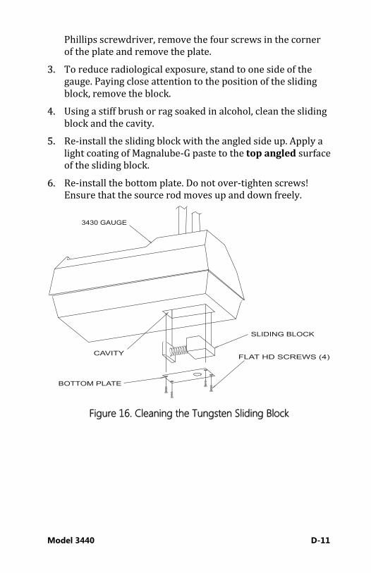
Model 3440 D-11
Phillips screwdriver, remove the four screws in the corner of the plate and remove the plate.
33.. To reduce radiological exposure, stand to one side of the gauge. Paying close attention to the position of the sliding block, remove the block.
44.. Using a stiff brush or rag soaked in alcohol, clean the sliding block and the cavity.
55.. Re-install the sliding block with the angled side up. Apply a light coating of Magnalube-G paste to the top angled surface of the sliding block.
66.. Re-install the bottom plate. Do not over-tighten screws! Ensure that the source rod moves up and down freely.
Figure 16. Cleaning the Tungsten Sliding Block
D–12
Leak Testing Unless specified otherwise by your license or state regulations, the gauge must be leak tested at intervals not exceeding 12 months to ensure the integrity of the radioactive source encapsulation. Sample analysis must be performed by a licensed laboratory only. Using the Troxler Model 3880 Leak Test Kit (PN 102868) and accompanying instructions, perform the following procedure:
WARNING!
Ensure that the source rod is in the SAFE position (see Figure 8 on page 3–5).
11.. Write the date, gauge model number, and serial number on the sample form and label.
22.. Remove the control panel from the gauge topshell. Locate the yellow radiation label on the top surface of the base.
33.. Holding the wipe disk with the tongs, wipe the radiation label.
44.. Turn the gauge on its side and locate the opening where the source rod extends through the gauge base.
55.. Holding the wipe disk with tongs, wipe the area around and inside the opening where the source rod extends from the gauge base.
66.. Pack the disk, as instructed, in the envelope and mail to Troxler Electronic Laboratories, Inc. for analysis.
77.. Secure the gauge properly.

Model 3440 D-13
RReegguullaattoorryy RReeqquuiirreemmeennttss This section summarizes the licensing and training requirements that pertain to ownership or operation of a nuclear gauge. This section also provides information on the proper disposal of the gauge, as well as emergency procedures to follow if the gauge is lost, stolen, or damaged.
Licensing In the United States, possession and use of the radioactive materials in a nuclear gauge require a license issued by the U.S. Nuclear Regulatory Commission (NRC) or an Agreement State licensing agency. Detailed information on obtaining a license is contained in the Troxler Licensing Guide. Copies of this guide are available from Troxler, or can be downloaded from the Troxler website: www.troxlerlabs.com. To purchase a nuclear gauge in Canada, an owner must obtain a radioisotope license from the Canadian Nuclear Safety Commission (CNSC). The owner should obtain copies of the CNSC Regulations and the Transportation of Dangerous Goods Act and Regulations. For other countries, please consult your local regulatory agency.
Training In the United States, anyone working with or near radioactive materials must complete a radiation safety training course to be designated an authorized user. Authorized users must be trained in the precautions and procedures to minimize radiation exposure; applicable regulatory requirements; and the operating, emergency, maintenance, and transportation procedures for the gauge. Troxler offers training classes designed to meet regulatory agency training requirements for nuclear gauge users.

D–14
Disposal A nuclear gauge contains licensed radioactive material. At the end of a gauge’s service life, it must not be discarded as ordinary trash, recycled as scrap material, or abandoned. Instead, a nuclear gauge must be transferred to an authorized recipient licensed by the NRC or an Agreement State. For further information on gauge disposal, contact Troxler.
Emergency Procedures If the nuclear gauge is lost or stolen, then immediately notify the gauge owner’s Radiation Safety Officer (RSO). The gauge owner should complete the emergency contact information on the lines furnished below. (Note that company refers to the gauge owner’s company, not Troxler Electronic Laboratories.) This information should be readily available to the gauge operator at all times. The company RSO is _________________________________________________ Call the RSO at The regulatory agency is ____________________________________________ Call the agency at If a gauge is damaged, then follow the steps below: 11.. Locate the gauge and/or sources. 22.. Do not touch or move the gauge. 33.. Immediately rope off an area around the nuclear gauge
and/or sources. A radius of 15 ft. (5 m) is sufficient. Do not leave the area unattended.
44.. Keep all unauthorized personnel from the nuclear gauge. 55.. If a vehicle is involved, it must be stopped until the extent of
contamination, if any, can be established.
Model 3440 D-15
66.. The gauge user should perform a visual inspection of the nuclear gauge to determine if the source housing or shielding has been damaged.
77.. Use a survey meter (such as the TroxAlert Survey Meter) to measure the dose rate at a distance of 1 m (3 ft.) from the gauge.
88.. Contact the company RSO (name and number given at the beginning of this section). Provide the RSO with the following: a. The date, time, and location of the accident b. The gauge model and serial number c. The nature of the accident d. The location and condition of the gauge and/or source e. The dose rate at 1 m (3 ft.) from the gauge
99.. If you are unable to reach the RSO, then call your regulatory agency (name and number given at the beginning of this section).
1100.. Follow the instructions of the RSO. The RSO may need to report the incident to the regulatory agency. The RSO may also be required to notify the USDOT of accidents during transport.
1111.. Before shipping a damaged gauge to Troxler, obtain an RGA (Returned Goods Authorization) number from the Troxler Customer Service Department, as described in the Returning
the Gauge for Service section on page A–22.
D–16
GGaauuggee UUssee PPrreeccaauuttiioonnss The following precautions should be observed when transporting, storing, maintaining, or operating the gauge. i Never touch the unshielded tip of the source rod with your
bare hands. The dose rates on contact with the source rod tip can result in exposures exceeding the annual dose limits to the skin of the extremities within a short time period (about 1 hour).
i When not taking readings, always keep the source rod in the SAFE (shielded) position. For added user safety, the source rod automatically retracts to the SAFE position when the gauge is lifted by the handle.
i If you do not hear a click when the gauge is raised to the SAFE position, look at the bottom of the gauge to verify that the tungsten sliding block is completely closed. If the gauge base opening is not completely closed by the sliding block, the sliding block may require cleaning. Refer to page D–10 for cleaning instructions.
i Do not store or transport the gauge unless the sliding block is completely closed. Increased radiation levels may cause excessive personnel radiation exposure and may violate transportation regulations.
i When preparing a test site, use the drill rod assembly to drill the test hole. Under no circumstances should the source rod of the gauge be used to drill holes.
i Do not tamper with or modify the gauge. Also, do not remove the sealed source from the gauge. Tampering with or modifying the gauge or removing the sealed source can be dangerous. Such actions are illegal unless authorized by your radioactive materials license.
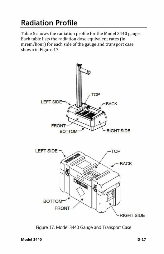
Model 3440 D-17
RRaaddiiaattiioonn PPrrooffiillee Table 5 shows the radiation profile for the Model 3440 gauge. Each table lists the radiation dose equivalent rates (in mrem/hour) for each side of the gauge and transport case shown in Figure 17.
Figure 17. Model 3440 Gauge and Transport Case

D–18
Table 5. Radiation Profile for Model 3440 Gauge
(Exposure rate in mrem/hour)
Surface 5 cm 30 cm 100 cm
Gam
ma
Neu
tron
Gam
ma
Neu
tron
Gam
ma
Neu
tron
Gam
ma
Neu
tron
GAUGE
Top 30.0 1.0 20.0 1.0 2.0 0.2 § §
Bottom 19.0 3.0 9.0 2.0 0.6 0.6 § §
Left Side 25.0 0.6 10.0 0.4 1.2 0.2 0.2 §
Right Side 8.0 1.2 3.0 0.4 1.0 0.2 0.2 §
Front 16.0 1.0 9.0 0.6 1.7 0.2 0.3 §
Back 25.0 1.0 13.0 0.8 2.0 0.3 0.4 §
GAUGE IN TRANSPORT CASE
Top 17.0 0.2 8.0 0.2 1.2 § 0.2 §
Bottom 6.0 0.2 4.0 0.2 1.0 0.2 0.4 §
Left Side 1.0 § 0.8 § 0.3 § § §
Right Side 9.0 2.0 4.0 1.6 0.5 1.0 § §
Front 9.0 0.4 6.5 0.2 2.0 § 0.2 §
Back 7.0 0.2 5.0 0.2 2.0 § 0.2 §
Model 3440 D-19
NOTES:
1. Radiation measurements were of a gauge containing a nominal 8 millicuries Cesium-137 gamma source and a nominal 40 millicuries Americium-241: Beryllium neutron source.
2. Gamma measurements were taken with a Bicron Micro Rem survey meter, Serial Number B464Y calibrated in January 2011.
3. Neutron measurements were taken with a Ludlum Model 12-4 survey meter, Serial Number 140077 calibrated in September 2011.
4. The symbol § denotes a radiation measurement of less than 0.2 millirem per hour.
5. Measurement position nomenclature for the gauge and transport case is shown in Figures 1 and 2.
6. Orientation of the gauge in the transport case is as follows: a. Back of the gauge to the front of the case b. Bottom of the gauge to the right side of the case, and c. Top of the gauge to the left side of the case.
Model 3440 E–1
AAppppeennddiixx EE:: UUnniitt CCoonnvveerrssiioonn
This chapter contains the following topics and tasks:
9 Measurement units 9 Radiological units

E–2
The Model 3440 gauges can display measurement results in either SI (metric) units or English units. Also, HM-181 of 49 CFR changes the standard units of radioactivity in the United States from the English unit of curies (Ci) to the SI unit of becquerel (Bq). This requires the shipper to convert the activity on the Bill of Lading from curies to becquerels (GBq). Until everyone is accustomed to the SI units, it is permitted to follow the SI units with the English units in parentheses to clarify the description [for example: 1.48 GBq (40 mCi)]. To help you convert from English units to SI units, the following provides SI conversion factors for common English units relevant to the gauge.
MMeeaassuurreemmeenntt UUnniittss 1 in. = 25.4 mm 1 in. = 2.54 cm
1 ft. = 30.48 cm 1 ft. = 0.3048 m
1 pcf = 16.02 kg/m3 1 pcf = 1.6 u 10-2 g/cm3
RRaaddiioollooggiiccaall UUnniittss 1 rem = 0.01 Sv
1 Ci = 37 GBq
1 mCi = 37 MBq 1 PCi = 37 kBq
The following table is provided to assist in converting from millicuries to gigabequerels:
mCi to GBq
8.0 0.30
40 1.48
Model 3440 F-1
AAppppeennddiixx FF:: SSttaannddaarrdd CCoouunntt LLoogg
Use the form in this appendix as a guide when recording the daily standard counts. To verify gauge stability, compare the daily standard count to the average of the last four recorded standard counts.

F–2
STANDARD COUNT LOG Gauge Serial Number _____________
Date MS DS Date MS DS

Model 3440 G-1
AAppppeennddiixx GG:: SSppeecciiaall EEuurrooppeeaann CCoonnssiiddeerraattiioonnss
This appendix covers the following topics:
9 Declaration of Conformity 9 Safety Warnings
This section applies only to those Troxler Model 3440 Surface Moisture-Density Gauges with the CE mark that are to be used in European countries.

G–2
DDeeccllaarraattiioonn ooff CCoonnffoorrmmiittyy Application of Council EMC Directive 89/336/EEC.
NOTE
The Low Voltage Directive 73/23/EEC does not apply to the Model 3440 Surface Moisture-Density Gauges because there are no voltages greater than 75 V dc that are accessible by the operator.
Standards to Which Conformity is Declared:
Guidance Documents:
Emissions: EN 61326-2:2006 Immunity: EN 61326-2:2006
Test Methods:
Emissions: EN 55011:1997 + A1:1999 + A2:2002, EN 61000-3-2:2006 +A1:2009 + A2:2009 EN 61000-3-3:1995 +A1:2001
Immunity: EN 61000-4-2:1995 + A1:1998 + A2:2001, EN 61000-4-3:2002, EN 61000-4-4:2004, EN 61000-4-5:1995 +A1:2001, EN 61000-4-6:1996 +A1:2001, EN 61000-4-8:1993 + A1:2001, EN61000-4-11:2004
Manufacturer: Troxler Electronic Laboratories, Inc. P.O. Box 12057 3008 Cornwallis Road Research Triangle Park, North Carolina 27709 U.S.A.
Apparatus: Model 3440 Surface Moisture-Density Gauges
Type of Equipment: Measurement, Control, and Laboratory Use
Class of Equipment: Class A

Model 3440 G-3
Year of Declaration: 2013
SSaaffeettyy WWaarrnniinnggss Owners are encouraged to require study of this manual before allowing anyone to use the gauge. A potential hazard does exist if improperly used. The sections of the manual covering radiological safety should be required reading for all users and potential users. If these sections are not completely understood, users should seek assistance from Troxler, an appointed Troxler representative, or others designated within the user's organization. The following list of safety warnings applies to gauges with the CE mark and that are to be used in European countries. In addition to these safety warnings, all other safety warnings and cautions throughout this manual apply to gauges with the CE mark. i There are no user-serviceable parts — only qualified service
personnel should remove shields or covers to attempt repairs.
i Do not remove any shields or covers. A high-voltage hazard is located under the baseboard cover.
i The dc adapter shall be used on properly fused vehicle cigarette lighters only.
i European countries shall use a proper IEC input cord to the European charger (specified by local laws and practices).
i Do not throw batteries into fires. There is a risk of explosion. i Use caution when lifting, moving, and/or carrying the gauge
— it is heavy. See Appendix D for radiation safety instructions

Model 3440 H-1
AAppppeennddiixx HH:: GGlloobbaall PPoossiittiioonniinngg SSyysstteemm ((GGPPSS))
This appendix covers the following topics:
9 GPS Accuracy

H–2
The Model 3440 Surface Moisture-Density Gauge can be equipped with an optional GPS (Global Positioning System) receiver that provides accurate information on the location (latitude and longitude) of the gauge.
GGPPSS AAccccuurraaccyy As described earlier, the Model 3440 gauge can be equipped with an optional GPS receiver that determines the location (latitude and longitude) of the gauge. This information is stored with each gauge measurement. The GPS receiver used in the Model 3440 has Wide Area Augmentation System (WAAS) capabilities, which provides accuracy to within 3 m (10 ft.). However, the accuracy is dependent upon the user’s location and other factors as described below. The global positioning system is a satellite-based navigation system that consists of 24 satellites and a network of ground stations that monitor and control those satellites. The satellites orbit the earth at an altitude of approximately 11,000 miles and constantly transmit signal information back to earth. A GPS receiver uses this information to determine its location. To determine its latitude and longitude, a GPS receiver must receive the signals from at least three satellites. On average, the receiver used in the gauge is accurate to within 15 m (approximately 50 ft.) when receiving GPS data alone. However, the WAAS capabilities can increase the accuracy to within 3 m (10 ft.), as shown in Table 6. The accuracy of GPS information can be affected by a number of atmospheric forces and other conditions. The Wide Area Augmentation System (WAAS) corrects for these factors by placing GPS receivers at 25 known, precisely surveyed locations, called reference stations, across the United States. The reference stations determined a measured distance to each satellite using the signals received from the satellites. For each satellite, the stations compare the measured distance to the actual range (as calculated from its known position) to determine a differential
correction for each satellite
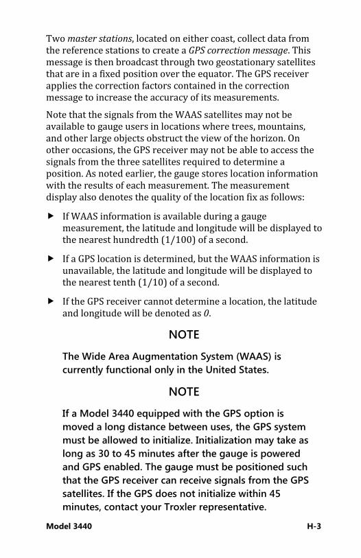
Model 3440 H-3
Two master stations, located on either coast, collect data from the reference stations to create a GPS correction message. This message is then broadcast through two geostationary satellites that are in a fixed position over the equator. The GPS receiver applies the correction factors contained in the correction message to increase the accuracy of its measurements. Note that the signals from the WAAS satellites may not be available to gauge users in locations where trees, mountains, and other large objects obstruct the view of the horizon. On other occasions, the GPS receiver may not be able to access the signals from the three satellites required to determine a position. As noted earlier, the gauge stores location information with the results of each measurement. The measurement display also denotes the quality of the location fix as follows: f If WAAS information is available during a gauge
measurement, the latitude and longitude will be displayed to the nearest hundredth (1/100) of a second.
f If a GPS location is determined, but the WAAS information is unavailable, the latitude and longitude will be displayed to the nearest tenth (1/10) of a second.
f If the GPS receiver cannot determine a location, the latitude and longitude will be denoted as 0.
NOTE
The Wide Area Augmentation System (WAAS) is currently functional only in the United States.
NOTE
If a Model 3440 equipped with the GPS option is moved a long distance between uses, the GPS system must be allowed to initialize. Initialization may take as long as 30 to 45 minutes after the gauge is powered and GPS enabled. The gauge must be positioned such that the GPS receiver can receive signals from the GPS satellites. If the GPS does not initialize within 45 minutes, contact your Troxler representative.

H–4
Table 6. GPS Position Accuracy
Quality of GPS Data Accuracy Fix Quality
GPS reading with WAAS
Within 3 m (10 ft.)
Latitude and longitude displayed to nearest 1/100 second
GPS reading without WAAS
Within 15 m (50 ft.)
Latitude and longitude displayed to nearest 1/10 second
No GPS reading N/A Latitude and longitude displayed as 0.

Warranty
INDEX
AC charger ............................................................................................... 1–5 Access code ................................................................................................ xv Accessories .............................................................................................. 1–5 Accident notification ............................................................................ C–3 Adapter, dc .............................................................................................. 1–5 Alkaline batteries ................................................................................ A–16 Alpha particles ....................................................................................... D–4 Americium-241
beryllium ........................................................................................................... 2–5 Americium-241:beryllium ...................................................... 4–16, D–8 Asphalt
Mode setup.................................................................................................... 3–14 Asphalt mode ....................................................................................... 4–29 ASTM) standards ................................................................................... 1–3 Atomic structure ................................................................................... D–2 Automatic
Depth mode .................................................................................................... 3–9 Shutdown ................................................................................................ 3–7, B–4
Automatic shutdown ........................................................................... 3–3 Auto-Store ............................................................................................. 8–12 Backscatter
Geometry .......................................................................................................... 2–3 Mode .................................................................................................................. 2–2
Battery .................................................................................................... A–11 Alkaline use ................................................................................................... A–16 Charge ................................................................................................... B–5, A–13 Charging ........................................................................................................ A–13 Low warning .................................................................................................... 9–6 Replace NiMH battery pack ................................................................... A–14 Specifications ........................................................................................ B–6, B–5 Status................................................................................................... 5–18, A–11
Becquerel ................................................................................................. D–3 Beeper, external ................................................................................... 5–16
Warranty
Beta particles.......................................................................................... D–4 Bottom density ....................................................................................... 5–9 Cable pinouts .......................................................................................... B–5 Calibration ................................................................................................ 2–7
Trench ................................................................................................................. 7–9 Canadian Nuclear Safety Commission (CNSC) .....1–4, D–13, C–4 Canadian shipping requirements .................................................... C–4 Cesium-137 ............................................................. 2–2, 4–16, D–9, D-8 Charge
Batteries .......................................................................................................... A–13 Charger, ac ............................................................................................... 1–5 Charging battery ................................................................................ A–13 Cleaning
Base and top shell ...................................................................................... A–17 Sliding block ................................................................................................. D–10
Clock/Calendar ........................................................................... 3–10, 9–3 Code of Federal Regulations (CFR) ................................................. 1–5 Contrast, display ................................................................................. A–10 Convert units ........................................................................................... E–2 Count
Standard ..........................................................................................................4–16 Time .................................................................................................................... 3–8
Count time ............................................................................................... 5–3 Create project ......................................................................................... 8–5 Curie .......................................................................................................... D–3 Customer name ......................................................................... 3–13, 9–3 Date
Format ..............................................................................................................3–12 Date, changing ..................................................................................... 3–11 DC adapter ............................................................................................... 1–5 Deactivate project ............................................................................... 8–11 Declaration of Conformity ....................................................... 1–4, G–2 Density .......................................................................................... 2–7, 4–29
Bottom ............................................................................................................... 5–9 Measurement theory .................................................................................... 2–2
Warranty
Offset ......................................................................................................... 2–7, 7–2 Offset enable ................................................................................................... 7–4
Department of Transportation (DOT) ............................................ C–1 Depth
Mode .................................................................................................................. 5–3 Of measurement ............................................................................................ 2–5
Detectors .................................................................................................. 1–5 Direct transmission
Geometry .......................................................................................................... 2–3 Mode .................................................................................................................. 2–2
Disable Moisture offset ............................................................................................... 7–8 Target value ..................................................................................................... 6–4
Display Contrast .......................................................................................................... A–10 Specifications .................................................................................................. B–5
Disposal ................................................................................................. D–14 Drift test .................................................................................................... 5–6 Drill rod ..................................................................................................... 1–5 Drill rod guide ........................................................................................ 1–5 Effect of top layer .................................................................................. 2–2 Emergency procedures .................................................................... D–14 Enable
Density offset .................................................................................................. 7–4 Moisture offset ............................................................................................... 7–5 Target value ..................................................................................................... 6–3
Encapsulation......................................................................................... D–8 Erase
Project ................................................................................................................ 8–6 Standard counts ............................................................................................. 9–5
Erratic readings ...................................................................................... 5–3 European considerations ................................................................... G–1 Exposure, limiting ................................................................................. D–6 Extraction tool ........................................................................................ 1–5 Fix quality (GPS) .................................................................................... H–3 Format

Warranty
Project output ................................................................................................. 8–8 Serial data ......................................................................................................... B–5
Gamma rays ........................................................................................... D–4 Gasket, replacing .................................................................... A–20, A–19 Gauge
Measurement geometry ............................................................................. 2–3 Source rod positions .................................................................................... 3–5
Geiger-Mueller (G-M) detectors ...................................................... 2–2 Geometry, gauge measurement ...................................................... 2–3 Global positioning system (GPS) ........................................ 5–17, H–1
Initialization ......................................................................................... 5–17, H–3 Half-life...................................................................................................... 9–4 Half-value layer (HVL) ......................................................................... D–7 Hazmat training ..................................................................................... C–3 Humidity ................................................................................................... F–6 ID number, sample ............................................................................. 8–12 Index rod positions ............................................................................... 3–5 Inspection
Daily .......................................................................................................... 3–6, D–9 Source rod ....................................................................................................... D–8 Upon receipt .................................................................................................... 1–7
International Air Transport Association (IATA) .......................... C–1 International Atomic Energy Agency (IAEA) ............................... C–1 K value (moisture offset) .................................................................... 7–5 Keypad............................................................................................. 3–3, B–5 Leak test ................................................................................................. D–12 Licensing ...................................................................................... 1–4, D–13 Liquid crystal display (LCD) ............................................................... B–5 Log, standard count ............................................................................. F–1 Low battery warning ............................................................................ 9–6 Lubricating source rod ..................................................................... A–19 Maintenance
Gasket .............................................................................................................. A–19 Mechanical .................................................................................................... A–17 Sliding block ................................................................................................. D–10

Warranty
Source rod bearing .................................................................................... A–18 Malfunction indicators ........................................................................ A–6 Manual
Depth mode .................................................................................................... 3–9 Store ................................................................................................................. 8–14
Measurement Asphalt mode ................................................................................................ 4–29 Mode ................................................................................................................ 3–14 Site preparation ........................................................................................... 4–22 Soil mode........................................................................................................ 4–25 Source rod positions .................................................................................... 3–5 Specifications .................................................................................................. B–2
Mechanical Maintenance ................................................................................................. A–17
Menu Target ................................................................................................................. 6–2
Mode Asphalt ............................................................................................................. 3–14 Backscatter ....................................................................................................... 2–2 Depth.................................................................................................................. 5–3 Direct transmission ....................................................................................... 2–2 Measurement ................................................................................................ 3–14 Nomograph ................................................................................................... 3–14 Ready .................................................................................................................. 3–6 Soil ..................................................................................................................... 3–14
Moisture Measurement theory ................................................................................... 2–5 New offset ........................................................................................................ 7–5 Offset ......................................................................................................... 2–7, 7–2 Offset disable .................................................................................................. 7–8 Offset enable ................................................................................................... 7–5 Offset, gauge-derived.................................................................................. 7–7 Offset, manual entry ..................................................................................... 7–6
Monitoring personnel......................................................................... D–7 Neutrons .................................................................................................. D–4 NiMH battery pack ............................................................................ A–14 Nomograph function ........................................................................... 5–9 Offset ................................................................................................ 2–7, 7–2

Warranty
Density ..................................................................................................... 2–7, 7–2 Menu ................................................................................................................... 7–3 Moisture .................................................................................................. 2–7, 7–2 Trench .............................................................................................. 2–7, 7–2, 7–9
Options ................................................................................................... 5–16 O-ring, replacing ................................................................................ A–20 Output project ........................................................................................ 8–7
Destination .....................................................................................................8–11 Parameter setup .................................................................................... 3–8 Parts
Gauge ................................................................................................................. 1–5 Replacement ................................................................................................. A–21
Percent air voids .................................................................................. 5–18 Photons .................................................................................................... D–4 Port
Serial ....................................................................................................... 8–7, 8–11 USB ................................................................................................ 8–7, 8–11, B–5
Position Safe ...................................................................................................................... 3–5 Source rod ........................................................................................................ 3–5
Precautions ........................................................................................... D–16 Precision ................................................................................................... B–2
Function ...........................................................................................................5–14 Print
Drift test ............................................................................................................. 5–8 Stat test .............................................................................................................. 5–5
Profile, radiation ................................................................................... D–17 Project
Create ................................................................................................................. 8–5 Deactivate .......................................................................................................8–11 Erase .................................................................................................................... 8–6 Menu ................................................................................................................... 8–2 Output data...................................................................................................... 8–7 Output destination ......................................................................................8–11 Output format ................................................................................................. 8–8 Print data ........................................................................................................... 8–7 Select .................................................................................................................. 8–3
Warranty
View .................................................................................................................... 8–4 Radiation
Converting units ............................................................................................ E–2 Dose .................................................................................................................... D–5 Exposure ............................................................................................................ D–6 Monitoring ....................................................................................................... D–7 Profile .............................................................................................................. D–17 Safety .................................................................................................................. D–5 Specifications .................................................................................................. B–4 Theory ................................................................................................................ D–2 Types .................................................................................................................. D–4
Radioactivity ........................................................................................... D–3 Reading
Asphalt mode ................................................................................................ 4–29 Soil mode........................................................................................................ 4–25
Ready mode ............................................................................................ 3–6 Recall data.............................................................................................. 4–31 Recharge time ........................................................................................ B–5 Reference standard block ...................................................... 1–5, 4–16 Regulations ................................................................................. 1–4, D–13
Canadian shipping ........................................................................................ C–4 U.S. shipping.................................................................................................... C–2
Replace Gasket and O-ring ...................................................................................... A–20 NiMH battery pack..................................................................................... A–14
Replacement Gaskets ........................................................................................................... A–19 Parts ................................................................................................................. A–21
Safe position ........................................................................................... 3–5 Safety warnings (European countries) .......................................... G–3 Sample identification (ID) number ............................................... 8–12 Scraper plate ........................................................................................... 1–5 Self-test ..................................................................................................... 3–6 Serial
Data format ...................................................................................................... B–5 Port .......................................................................................................... 8–7, 8–11
Service .................................................................................................... A–23

Warranty
Service Centers ............................................................................................ ii Set units .................................................................................................... 5–3 Setup
Depth .................................................................................................................. 3–9 First-time ........................................................................................................... 3–8 Measurement Units....................................................................................... 3–9 Menu ................................................................................................................... 5–2
Shielding .................................................................................................. D–7 Shipper's Declaration for Dangerous Goods .............................. C–2 Shipping ................................................................................................... D–1
Canadian requirements ............................................................................... C–4 Case ..................................................................................................................... F–6 U.S. requirements .......................................................................................... C–2
Shutdown, automatic ........................................................ 3–3, 3–7, B–4 Site
Asphalt measurement ................................................................................4–24 Preparation .....................................................................................................4–22 Soil and base course measurement .....................................................4–22 Standard count .............................................................................................4–16
Sliding block, cleaning ..................................................................... D–10 Software reset ......................................................................................... 9–7 Soil
Mode setup ....................................................................................................3–14 Source
Americium-241:beryllium (Am-241:Be) ................................................. 9–4 Cesium-137 (Cs-137) .................................................................................... 9–4 Decay .................................................................................................................. 9–4 Encapsulation ................................................................................................. D–8 Rod inspection ............................................................................................... D–8 Rod lubrication ............................................................................................ A–19 Shielding .......................................................................................................... D–7
Source rod Bearing maintenance ................................................................................ A–18 Positions ............................................................................................................ 3–5
Special European considerations ................................................... G–1 Specifications .......................................................................................... B–1
Measurement .................................................................................................. B–2

Warranty
Standard count .................................................................................... 4–16 Log ....................................................................................................................... F–1 View .................................................................................................................. 4–21
Stat test ..................................................................................................... 5–3 Status
Battery ................................................................................................. 5–18, A–11 Store
Auto .................................................................................................................. 8–12 Manual ............................................................................................................. 8–14 Measurements .................................................................................. 4–28, 4–31 Target value ..................................................................................................... 6–4
Taking a measurement Asphalt mode ................................................................................................ 4–29 Soil mode........................................................................................................ 4–25
Target Menu .................................................................................................................. 6–2
Target value Disable ............................................................................................................... 6–4 Edit ...................................................................................................................... 6–3 Enable................................................................................................................. 6–3 Store ................................................................................................................... 6–4
TDG ............................................................................................................. 1–4 Temperature ............................................................................................ F–6 Test
Drift ..................................................................................................................... 5–6 Stat ...................................................................................................................... 5–3
Theory Density measurement .................................................................................. 2–2 Moisture measurement ............................................................................... 2–5 Offset .................................................................................................................. 2–7 Radiation ........................................................................................................... D–2
Thermoluminescent dosimeter (TLD) ........................................... D–7 Time
Count .................................................................................................................. 5–3 Format .............................................................................................................. 3–12
Time, changing ..................................................................................... 3–11 Time, count .............................................................................................. 3–8

Warranty
Top layer effect ...................................................................................... 2–2 Training ........................................................................................ 1–4, D–13
Hazmat ............................................................................................................... C–3 Transport case ............................................................................... 1–5, F–6 Transport Packaging of Radioactive Materials Regulations
(TPRM) .................................................................................................. C–4 Transportation
Canadian requirements ............................................................................... C–4 U.S. requirements .......................................................................................... C–2
Transportation Guide ........................................................................... 1–7 Transportation of Dangerous Goods Act and Regulations
(TDG) ..................................................................................................... C–4 Trench offset ........................................................................ 2–7, 7–2, 7–9 Troubleshooting .................................................................................... A–2 U.S. shipping requirements ............................................................... C–2 Unit conversion ...................................................................................... E–2 Units, measurement ............................................................................. 5–3 Unpacking ................................................................................................ 1–7 USB port.............................................................................. 8–7, 8–11, B–5
Compatible devices........................................................................... 8–11, B–5 User ID ........................................................................................... 3–13, 9–3 Vertical structure offset ....................................................................... 7–9 View
Drift test ............................................................................................................. 5–8 Project ................................................................................................................ 8–4 Standard counts ...........................................................................................4–21 Stat test .............................................................................................................. 5–5
Void ratio ................................................................................................ 5–18 Wide Area Augmentation System (WAAS) ................................. H–2
TROXLER ELECTRONIC LABORATORIES, INC.
LIMITED WARRANTY TROXLER ELECTRONIC LABORATORIES, INC., and subsidiary, TROXLER

Warranty
INTERNATIONAL, LTD., hereinafter referred to as “TROXLER,” warrants this instrument, Model _______, Serial Number __________, against defects in material and workmanship for a period of twelve (12) months from date of shipment. For products sold through authorized TROXLER representatives, the date of shipment will be as of the transfer from representative to purchaser. During the applicable warranty period, TROXLER’s obligation under this warranty shall be limited exclusively to the repair at a TROXLER facility at no charge, except for shipping to and from TROXLER’S plant, of any instrument which may prove defective under normal use and which TROXLER’s examination shall disclose to its satisfaction to be thus defective. Normal use is defined for the purpose of this warranty as operation under normal load, usage, and conditions with proper care and maintenance and competent supervision. In no event shall TROXLER be held liable for damages, delays, or losses consequential, incidental, or otherwise attributable to the failure of this instrument. TROXLER’s liability being specifically limited to repair as stated hereinabove. This warranty is automatically initiated except where modified by contractual or other written and signed agreement.
THERE ARE NO WARRANTIES WHICH EXTEND BEYOND THE DESCRIPTION ON THE FACE HEREOF, AND THIS WARRANTY IS EXPRESSLY IN LIEU OF ALL OTHER WARRANTIES, EXPRESSED OR IMPLIED, AND TROXLER NEITHER ASSUMES, NOR AUTHORIZES ANYONE TO ASSUME FOR IT ANY OTHER LIABILITY IN CONNECTION WITH THE SALE OF THE INSTRUMENT. THIS WARRANTY SHALL NOT APPLY TO THE INSTRUMENT OR ANY PART THEREOF, WHICH HAS BEEN SUBJECTED TO DAMAGE BY ACCIDENT, NEGLIGENCE, ALTERATION, ABUSE, MISUSE, OR SERVICE NOT AUTHORIZED IN WRITING BY TROXLER. SUCH DAMAGE TO INCLUDE BUT NOT BE LIMITED TO BURNING OF CIRCUIT BOARDS AND HARNESS FROM IMPROPER SOLDERING TECHNIQUES AND DAMAGE TO THE INSTRUMENT DUE TO PURCHASER’S FAILURE TO PERFORM MAINTENANCE AS OUTLINED IN THE AUTHORIZED OPERATOR’S MANUAL. DUE TO THE NATURE OF THEIR USE, MECHANICAL ACCESSORY PARTS AND BATTERIES ARE WARRANTED FOR 90 DAYS ONLY FROM DATE OF SHIPMENT.
TROXLER ELECTRONIC LABORATORIES, INC. 3008 E. Cornwallis Road Post Office Box 12057
Research Triangle Park, NC 27709 USA
NOTICE TO CONSUMERS Any disclaimer or limitation on the remedies expressed above shall not be effective to the extent prohibited by state or federal law.
NOTE: THIS WARRANTY EXCLUDES DAMAGE INCURRED IN SHIPMENT. IF THIS INSTRUMENT IS RECEIVED IN DAMAGED CONDITION, THE CARRIER SHOULD BE CONTACTED IMMEDIATELY. ALL CLAIMS FOR DAMAGE IN TRANSIT SHOULD BE FILED WITH THE CARRIER. IF REQUESTED, TROXLER WILL AID IN FILING OF CLAIMS AND/OR LOCATING PRODUCTS LOST IN TRANSIT.

#2, 1540 Hastings Cres. S.E. Calgary,AB. T2G 4E1
+1-866-300-9012
GlobalTroxler
w w w . g l o b a l t r o x l e r . c a