model bi evinrude etec series 25-30 hp - outboard … · model bi evinrude etec series 25-30 hp ......
TRANSCRIPT

MODEL BI EVINRUDE ETEC SERIES 25-30 HP ASSEMBLY INSTRUCTIONS
2 CYLINDER, 2 STROKE, 35.1 CU. IN. STARTING 2010
1
1. Place the motor on the transom of your boat so that it is mounted vertically, in the normal fashion. Remove
the two screws and water inlet screens from the gearbox. Remove the upper bolt from the shift rod coupling. Remove the six bolts holding the gear box and lower the gearbox.
2. The shift rod, which now hangs below the exhaust housing mounting face, would interfere with the jet drive
and must be shortened. CAUTION: Using a hacksaw, cut exactly 3 inches off of the end. This is more easily done by placing a small wooden block between the rod and the exhaust housing and using a “C” clamp to hold the rod steady against the block and exhaust housing. Do not throw away the end cut off (see instruction number 3). Using a file, bevel the sharp edges of the rod, which will later slide up and dowin in a guide hole in the jet drive bearing housing.
3. If you wish to change back to the propeller drive at a later date, we have available a threading die kit and
threaded coupling with instructions for threading the cut off ends of the shift rod. This will make it easy to switch back and forth between prop and jet. The stainless steel coupling costs extra and the cost of the threading kit is refundable after return in good condition. Tool #465, Coupling #464.
4. Next, install the jet pump driveshaft assembly into the spiral pump housing, locking it in place with two #10-
24 fil head screws and spring lock washers. 5. Remove the water pump assembly from the gear box, including the drive key, stainless pump plate, and
gasket. Install this assembly in the jet drive using six 1/4-20 x 1 hex head bolts – no washers. Be sure the pump is in good condition and that the rubber impeller fingers are all pointing backwards when turning the driveshaft in a clockwise direction looking down from above. Don’t forget the impeller drive key. Remove the rubber sealing sleeve from the top of the water pump. Install this sleeve in the brass water tube extension. Apply some grease to the o-ring and inside the rubber sleeve. Slide the brass tube inside the water pump.
6. A 3/4 inch adapter plate is attached to the exhaust housing to hold the jet drive. Install the adapter plate using
the six bolts from the gearbox. Tighten to 12 ft-lbs. No flat washers are used. Use blue loctite. 7. Next, attach the jet drive to the motor. Using four 5/16-18 x 2 3/4 bolts with lock washers from below and
one 3/8-16 x 1 1/4 bolt from above rear with lock washer. Grease the bolt threads, driveshaft spline, and shift rod. Tighten the 5/16 bolts to 12 ft-lbs and the 3/8 bolts to 18 ft-lbs.
8. Next, install the impeller. Grease the shaft threads, key and impeller bore. Place the plastic sleeve inside the
impeller; hold the key in the nose of the impeller with your forefinger and slide onto the driveshaft. Install the shim washers, torsional damper and nut retainer on the shaft, and bring the nut up snug by hand.
Place the liner wear ring in position and observe the clearance between the impeller blade edge and the intake
liner. When, after use in sand and gravel, the blade clearance becomes more than about 1/32” between the
impeller edge and the water intake liner, one or more of the shim washers can be transferred from the bottom stack to the top of the impeller, which moves the impeller down into the tapered casing to reduce the clearance.
Shims should not be used above the impeller on new installations where no wear has occurred unless the
blade clearance exceeds 1/32 inch. Insufficient blade clearance will do more harm than good from any performance gains it might provide.

MODEL BI EVINRUDE ETEC SERIES 25-30 HP ASSEMBLY INSTRUCTIONS
2 CYLINDER, 2 STROKE, 35.1 CU. IN. STARTING 2010
2
When the impeller clearance is satisfactory, bump the nut up tight with a wrench. If the ears of the retainer do not line up with the flats on the nut, spin the nut off, turn the retainer over, and tighten the nut again. In one of these two positions you will have alignment and can fold the ears up against the nut to retain it. The flat in the retainer is angled to the ears to allow this.
9. Place the intake casing in position with the lower end at the rear and tighten the six 1/4-20 fiber lock nuts. No
lock washers are used. Grease the threads. See the diagram on page 3. 10. If your jet drive was ordered for use with a steering tiller handle, see the attached shift cable assembly
instruction page for installing shift cable #2054. 11. For remote control steering, attach the shift cable and the cable anchor bracket to the jet drive. On E-TEC
motors, move the neutral switch inside the cowling to the forward position. To winterize the motor, temporarily move the switch to the neutral position.
12. With the shift handle in forward and the reverse gate in forward, with the cam roller at the end of the slot,
adjust the cable and/or cable anchor position to this condition. Shift to reverse and back to forward. The roller should be at the end of the cam slot such that the gate cannot be forcibly rotated toward reverse. Pull on the gate by hand to verify this. If this forward lock condition is not met, readjust the cable positions.
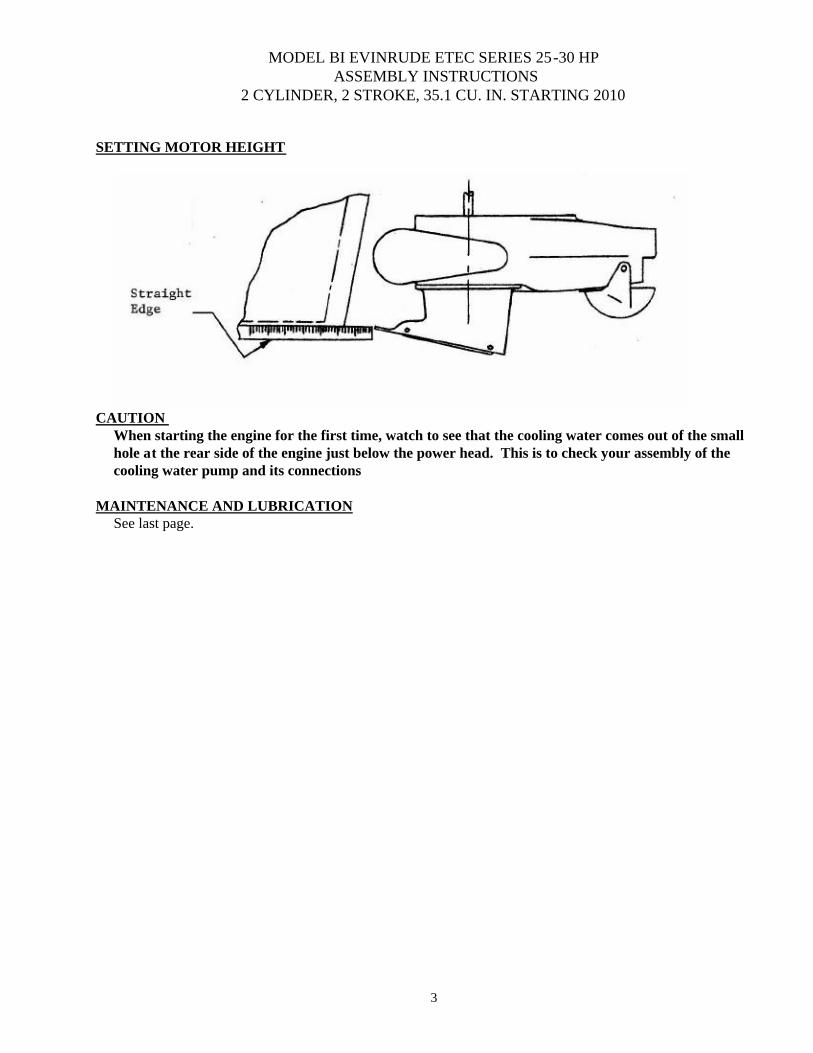
13. When converting to jet drive, your motor will have to be raised to height shown in the diagram below,
using a straight edge under the boat. Test run the boat and then raise or lower the motor 5/16 inch at a time to obtain the best results.
The motor has four sets of upper mounting holes. You will use one set to begin with. Mark pencil lines on
the boat transom through the other sets. Then if you wish to go up or down 5/16 inch, you can drill one alternate set of holes 5/16 inch up or down from the pencil marks. By alternating between these two sets of transom holes and the four sets of motor holes, the motor can be moved in 5/16 inch increments over almost one inch. The transom height should be about 21 ” measured vertically from the boat bottom for short shaft motors, and 26" for long shaft motors.
If you raise it too much it will suck air and cavitate, either on start up or when banking on turns. When
cavitating, the motor over speeds in spurts and shakes considerably i n the motor mount. This is not a normal condition and should be avoided by proper adjustment of motor height on each individual boat. If you lower it too much you will have excessive drag, therefore mount the motor as high as possible without allowing cavitation.
The cooling system can be flushed by removing the hex bolt next to the grease fitting. A hose coupling,
24789A1, is available from a Mercury dealer. Turn on the water gently, and start the motor set to idle. Watch for cooling water at the tell tale. Adjust the water pressure if needed. Be sure to replace the bolt after flushing.
MODEL BI EVINRUDE ETEC SERIES 25-30 HP ASSEMBLY INSTRUCTIONS
2 CYLINDER, 2 STROKE, 35.1 CU. IN. STARTING 2010
3
SETTING MOTOR HEIGHT
CAUTION
When starting the engine for the first time, watch to see that the cooling water comes out of the small hole at the rear side of the engine just below the power head. This is to check your assembly of the cooling water pump and its connections.
MAINTENANCE AND LUBRICATION
See last page.

MAINTENANCE AND LUBRICATION OUTBOARD JET DRIVE
3
BEARING LUBRICATION
A grease gun and tube of grease is supplied with your jet drive. We recommend greasing the bearing every 10 hours. Make greasing a part of your cleanup after the days use. Pump in just enough grease to fill the lube hose. Then reconnect the lube hose coupling to the zerk grease fitting. Every 30-40 hours, pump in extra grease so as to purge any moisture. The texture of the grease coming out gives an indication of conditions inside the bearing housing. A gradual increase in moisture content indicates seal wear. If the grease begins to turn dark, dirty gray, the bearing and seals should be inspected and replaced if necessary. Some discoloration of the grease is normal during the break in period on new sets of seals. We have selected a water resistant grease of the proper consistency for this application. If you use a substitute grease, be sure it is water resistant and of the same consistency. IMPELLER Your jet drive is equipped with a key to protect the unit in the event of a rock jam. This can be reached by removing the water intake, and then the driveshaft nut, similar to a propeller drive. After replacing the key, pull the shaft nut up tight to remove any play between the impeller and shaft. Note the position of the impeller shim washers, and replace them in the same order. REVERSE GATE MECHANISM Occasionally check adjustment of the gate shifting linkage. In “forward” the gate should be firmly locked in position. Pull on the gate by hand to verify this. This will prevent wave action from accidentally shifting the gate into reverse as the boat is violently maneuvered GENERAL Check all mounting bolts, intake screws, linkage connections, etc., occasionally to be sure they are tight. SALT WATER USE Aluminum and stainless steel have been used in the construction of your jet drive. These materials have either been treated or are inherently resistant to corrosion. It is recommended, however, that when not in use the motor be tipped up so that the jet unit is out of the water. When used in salt water more than in fresh water, remove mounting hardware, grease, and reassemble once a year. Failure to do this may result in hardware that is difficult if not impossible to remove at a later date. GUARANTEE Due to inflexible government regulation, we do not have a written warranty. We have, however, a good reputation for fairness with our customers which we intend to maintain. If you think you have a warranty situation, regarding material, workmanship, call us before making repairs. Specialty Manufacturing Company Outboard Jets 2035 Edison Avenue San Leandro, CA 94577

EVINRUDE SHIFT ROD MODIFICATION FOR MODEL BI 25-30 HP, 2 CYLINDER, 2 STROKE, 35.1 CU. IN. STARTING 2010
1
1. To install the jet drive, it is necessary to cut the shift rod which extends below the engine exhaust
housing mounting flange. The cut ends of the rod can then be threaded to receive a coupling so that the gearbox can be remounted on the engine when desired.
2. Caution: Using a hacksaw, cut exactly 3 inches off the end of the shift rod. Use the rod
clamping block, #1478, to support the rod. Tighten the rod bolts firmly. Using a felt pen, mark a line along the rod so you can observe that the rod does not twist while being threaded. Using a file, bevel the cut edges of each piece to allow starting the threading die.
3. Use oil on the rod and die. Thread the upper rod (in the engine) back ½ inch. Be gentle when
turning the die with a wrench so as not to twist the rod and possibly break it off up in the engine. File off any burrs on the rod where the thread ends.
4. Grip the lower end of the cut off rod in a vise and thread it back 1/2 inch. Again, holding the rod in
a vise, slide the drilled end of the coupling over the rod and thread it into place, jamming the ends of the threads to lock the coupling permanently to the rod. Install the rod in the gearbox, leaving the clamp bolt loose so that the rod and coupling can be turned to engage the upper shift rod threads when installing the gearbox.
5. When mounting the gearbox, slide the gearbox into place while threading the coupling onto the
upper shift rod. Do not over tighten. Lock the clamp bolt which secures the rod from turning.


MODEL BI ETEC EVINRUDE 25-30HP STARTING 2010
REF QTY PART DESCRIPTION REF QTY PART DESCRIPTIONNO. NO.
1 6 576 BOLT HEX HD 1/4-20 X 1 50 4 517 SPIROLOX RR-150S2 6 591 BOLT HEX HD M8-1.25 X 30MM 51 2 506 SEAL INNER3 1 2053 WATER TUBE EXT BI W/O-RING 52 2 507 SEAL OUTTER 6324-S4 1 532.2 O RING 10MM X 2MM 53 2 526 O RING 568-1355 1 636 WASHER SPRING LOCK M10 54 1 1472 BEARING CARRIER W/SEALS & O RINGS AM, BI7 1 2049 ADAPTER PLATE BI 55 3 521 O RING 568-011 1/16X5/16X7/168 10 640 WASHER SPRING LOCK 5/16 56 2 637 WASHER SPRING LOCK 1/49 4 599 BOLT HEX HD 5/16-18 X 2 3/4 57 2 561 FIL HD SLOTTED 10-24 X 5/8
10 1 606 BOLT HEX HD 3/8-16 X 1 1/4 58 1 8.21 IMPELLER 5 7/8, ALUM/ ZINC, W/36.1 SLEEVE 2048 VOLUTE WITH GATE BI CAM 59 1 36.1 SHAFT SLEEVE PLASTIC MED.
11 1 2047 VOLUTE WITH EXHAUST TUBE BI 60 1 1705 IMPELLER TEE KEY - 1/2 ROUND 12 1 80 EXHAUST TUBE ASSY MEDIUM 2 61 7 21 SHIM WASHER MEDIUM13 1 846 CLIP EXHAUST TUBE 1 62 1 805 NUT KEEPER MED/PKG 2 PER BAG14 2 621 NYLOC 10-32 63 1 22.1 SHAFT NUT 5/8-18 BRASS15 1 975 LUBE HOSE ASSY 1448 INTAKE ASSY 5 7/8 FLANGED W\ GRILL & LINER16 1 539 ZIRC FITTING 1/4-28 64 1 1678 LINER 5 7/8 FLANGED17 1 550 GREASE GUN 65 6 1300 STUD - INTAKE MEDIUM18 1 552 GREASE TUBE NO 630-AA 66 6 623 NYLOC 1/4-2019 1 1175 REVERSE GATE, MEDIUM 67 1 1326 INTAKE PAINTED ONLY MED FLANGED20 2 535 NYLINER 3/8 1D X 11/16 68 2 14 GILL ROD21 1 1177 SPRING GATE PIVOT 3/8 69 9 16 GILL BAR MEDIUM22 2 822 PIN GATE PIVOT 3/8 MEDIUM 170 BRACKET ASSY OMC W/CLIP & HARDWARE23 1 1043 SHAFT ROLLER 71 1 156 BRACKET CABLE SUPT OMC, MORSE24 3 624 NYLOC 1/4-28 72 1 546 CLIP OMC 30573625 1 1042 ROLLER ASSY 73 2 562 PAN HD PHILLIPS 10-32 X 1/226 8 635 1/4 WASHER AN960C416 74 2 635 1/4 WASHER AN960C41627 1 1035 SHIFT CAM MEDIUM 75 2 572 BOLT HEX HD 1/4-20 X 5/828 1 62 NUT HEX JAM 1/4-28 76 2 621 NYLOC 10-3229 1 1199 PIVOT - CABLE END 77 1 1718 TORSIONAL DAMPER 5/830 1 638 WASHER SPRING LOCK 1/431 1 622 NUT HEX 1/4-2832 1 1037 BUSHING CAM33 1 1038 WASHER CAM34 2 1039 SHIM - CAM35 1 1036 CAM ECCENTRIC DRILLED36 1 574.1 BOLT HEX HD 1/4-20 X 1 PATCH37 2 574 BOLT HEX HD 1/4-20 X 3/4 PATCH38 1 1170 SPRING GATE BUMPER39 1 1169 GATE BUMPER40 1 559.2 FIL HD SLOTTED 10-32 X 1 1/4 PATCH41 1 2051 SHAFT ONLY, BI SHORT, 14T 24 1/4 LG
1 2052 SHAFT ASSY COMPLETE, BI SHORT, 14T41 1 2056 SHAFT ONLY, BI LONG, 14T 29 1/4 LG
1 2057 SHAFT ASSY COMPLETE, BI LONG, 14T42 1 41 SHAFT BEARING THRUST RING 43 1 477 COLLAR BACKFIT 720544 1 1536 THRUST WASHER45 1 504 BEARING 7205B-UA46 1 511 TRUARC 5100-9847 1 1535 SPACER48 1 512 TRUARC N5002-212ZD49 1 433 UPPER SEAL CARRIER W/SEALS & O RINGS
SIZE TORQUE
1 /4-20 (M6) 8-9 FT-LBS 5 /16-18 (M 8) 12 FT-LBS 3/8-16 (M10) 22 FT-LBS
TILLER STEERING: SHIFT CABLE ASSY 2054, SEE PG. 34.8 BEARING, SEAL, SNAP & “O” RING KIT 803.1
- 67 -

BI TILLER SHIFT CABLE ASSY 2010 EVINRUDE 25-30 HP ETEC
2054
1. Remove the lower cover from the tiller handle. Remove the clamp holding the control cables to provide access inside the handle. 2. Carefully cut out and align the drilling template, holding it in place with masking tape. Center punch and drill the two 3/16 holes. 3. Install the two slotted 10-24 x 5/8 screws, from the inside to secure the cable clamp #1869 with the two 10-24 fiber lock nuts. See the photo for to position the clamp direction. 4. Replace the cable clamp and lower cover. 5. Remove the screw holding the hand grip on the shift handle. Carefully drill through the grip and the handle with an F (.257) drill for a 2 ¾ long ¼-20 through bolt. Start the drill from both ends to minimize drill drift. 6. Install the bolt with a flat washer and plain nut. Tighten the nut to draw the bolt hex head into the plastic handle until it bottoms and is tight. 7. Screw the ball rod ends on the 4 foot cable until they bottom. The cable support bracket on the jet drive should be slid all the way forward and locked. 8. The jet kits come with BRP cable type fittings for remote controls. The tiller sift cable kit is Morse and has the appropriate fittings which can be substituted. 9. Route the cable as shown in the photos and secure the hardware. No further cable adjustments need to be made as there is ample travel in the shift handle to reach reverse and lock in forward. The lower hole on the cable anchor bracket on the jet drive is slotted to allow rotating the clip to align the cable for free travel. CAUTION: You must return the throttle to idle before shifting.

BI TILLER SHIFT CABLE ASSY 2010 EVINRUDE 25-30 HP ETEC
2054 SHIFT CABLE ROUTING

SHIFT CABLE ASSEMBLYBRP MODEL BI E-TEC
TILLER STEERING2054
REF QTY PART NO. DESCRIPTION1 1 547 CABLE 4 FT MOR 33C SUPREME3 1 542 SHIM MORSE A0357774 1 543 CLAMP CHRYS 1543175 4 561 FIL HD SLOTTED 10-24 X 5/86 1 635 1/4 WASHER AN960C4167 1 628 NUT HEX 1/4-208 4 619 NYLOC 10-249 2 621.1 NUT HEX 10-32
10 2 553.2 BALL END 1/4 X 10-32 CABLE11 1 573 BOLT HEX HD 1/4-20 X 3/412 2 623 NYLOC 1/4-2013 1 1869 CABLE ANCHOR MORSE FORMED14 1 582 BOLT HEX HD 1/4-20 X 2 3/4 FULL THREAD
