model cflc - waterloo...
TRANSCRIPT

Model CFLCClearFire
Condensing Boiler
Operation and Maintenance Manual
750-36311/2013
4,000 - 12,000 MBTU

ii
Do not use this boiler if any part has been underwater. Immediately call your Cleaver-Brooks ser-vice representative to inspect the boiler and to re-place any part of the control system and any gascontrol which has been under water.
! DANGERWARNING
! DANGERWARNINGIf the information in this manual is not fol-lowed exactly, a fire or explosion may re-sult causing property damage, personalinjury or loss of life.
— Do not store or use gasoline or otherflammable vapors and liquids in the vicin-ity of this or any other appliance.— WHAT TO DO IF YOU SMELL GAS• Do not try to light any appliance.• Do not touch any electrical switch; do not use
any phone in your building.• Immediately call your gas supplier from a
neighbor's phone. Follow the gas supplier's instructions.
• If you cannot reach your gas supplier, call the fire department.
— Installation and service must be performed by a qualified Cleaver-Brooks, service agency or the gas supplier.
Improper installation, adjustment, ser-vice, or maintenance can cause equip-ment damage, personal injury, or death.Refer to the Operation and Maintenancemanual provided with the boiler. Installa-tion and service must be performed by aqualified Cleaver-Brooks service provid-
! DANGERWARNING
! DANGERWARNING
Be sure the fuel supply which the boilerwas designed to operate on is the sametype as specified on the boiler nameplate.
! DANGERWARNING
Should overheating occur or the gas sup-ply valve fail to shut off, do not turn off ordisconnect the electrical supply to theboiler. Instead turn off the gas supply at alocation external to the boiler.
! DANGERWARNING
To minimize the possibility of serious personal in-jury, fire or damage to the equipment, never vio-late the following safety rules. — Always keep the area around the boiler free of combustible materials, gasoline, and other flam-mable liquids and vapors— Never cover the boiler, lean anything against it, stand on it, or in any way block the flow of fresh air to the boiler.
This manual must be maintained in legible condi-tion and kept adjacent to the boiler or in a safeplace for future reference. Contact your localCleaver-Brooks representative if additional manu-als are required.
Notice
Where required by the authority having jurisdic-tion, the installation must conform to the Standardfor Controls and Safety Devices for AutomaticallyFired Boilers, ANSI/ASME CSD-1.
Notice
The boiler and its individual shutoff valve must bedisconnected from the gas supply piping systemduring any pressure testing of that system at testpressures in excess of 1/2 psi (3.5 kPa).
! DANGERWARNING
The installation must conform to the requirementsof the authority having jurisdiction or, in the ab-sence of such requirements, to UL 795 Commer-cial-Industrial Gas Heating Equipment and/or theNational Fuel Gas Code, ANSI Z223.1
! DANGERWARNING

iii
Please direct purchase orders for replacement manuals to your local Cleaver-Brooks authorized representative.
Manual Part No. 750-363
11/2013 Printed in U.S.A.
Cleaver-Brooks 2013
CLEAVER-BROOKSModel CFLC
ClearFire Packaged Boiler
Condensing BoilerOperation and Maintenance Manual
iv
TO: Owners, Operators and/or Maintenance Personnel
This operating manual presents information that will help to properly operate and care for the equipment. Study its con-tents carefully. The unit will provide good service and continued operation if proper operating and maintenance instruc-tions are followed. No attempt should be made to operate the unit until the principles of operation and all of thecomponents are thoroughly understood. Failure to follow all applicable instructions and warnings may result in severepersonal injury or death.
It is the responsibility of the owner to train and advise not only his or her personnel, but the contractors' personnel whoare servicing, repairing or operating the equipment, in all safety aspects.
Cleaver-Brooks equipment is designed and engineered to give long life and excellent service on the job. The electricaland mechanical devices supplied as part of the unit were chosen because of their known ability to perform; however,proper operating techniques and maintenance procedures must be followed at all times. Although these components af-ford a high degree of protection and safety, operation of equipment is not to be considered free from all dangers andhazards inherent in handling and firing of fuel.
Any "automatic" features included in the design do not relieve the attendant of any responsibility. Such features merelyfree him of certain repetitive chores and give him more time to devote to the proper upkeep of equipment.
It is solely the operator’s responsibility to properly operate and maintain the equipment. No amount of written instructionscan replace intelligent thinking and reasoning and this manual is not intended to relieve the operating personnel of theresponsibility for proper operation. On the other hand, a thorough understanding of this manual is required before at-tempting to operate, maintain, service, or repair this equipment.
Because of state, local, or other applicable codes, there are a variety of electric controls and safety devices which varyconsiderably from one boiler to another. This manual contains information designed to show how a basic burner operates.
Operating controls will normally function for long periods of time and we have found that some operators become lax intheir daily or monthly testing, assuming that normal operation will continue indefinitely. Malfunctions of controls lead touneconomical operation and damage and, in most cases, these conditions can be traced directly to carelessness anddeficiencies in testing and maintenance.
It is recommended that a boiler room log or record be maintained. Recording of daily, weekly, monthly and yearly main-tenance activities and recording of any unusual operation will serve as a valuable guide to any necessary investigation.Most instances of major boiler damage are the result of operation with low water. We cannot emphasize too strongly theneed for the operator to periodically check his low water controls and to follow good maintenance and testing practices.Cross-connecting piping to low water devices must be internally inspected periodically to guard against any stoppageswhich could obstruct the free flow of water to the low water devices. Float bowls of these controls must be inspectedfrequently to check for the presence of foreign substances that would impede float ball movement.
The waterside condition of the pressure vessel is of extreme importance. Waterside surfaces should be inspected fre-quently to check for the presence of any mud, sludge, scale or corrosion.
It is essential to obtain the services of a qualified water treating company or a water consultant to recommend the properboiler water treating practices.
The operation of this equipment by the owner and his or her operating personnel must comply with all requirements orregulations of his insurance company and/or other authority having jurisdiction. In the event of any conflict or inconsis-tency between such requirements and the warnings or instructions contained herein, please contact Cleaver-Brooks be-fore proceeding.
DO NOT OPERATE, SERVICE, OR REPAIR THIS EQUIPMENT UNLESS YOU FULLY UNDERSTAND ALL APPLICABLE SECTIONS OF THIS MANUAL.
DO NOT ALLOW OTHERS TO OPERATE, SERVICE, OR REPAIR THIS EQUIPMENT UNLESS THEY FULLY UNDERSTAND ALL APPLICABLE SECTIONS OF THIS MANUAL.
FAILURE TO FOLLOW ALL APPLICABLE WARNINGS AND INSTRUCTIONS MAY RESULT IN SEVEREPERSONAL INJURY OR DEATH.
! DANGERWARNING

TABLE OF CONTENTS
Section 1 IntroductionCFLC Features and Benefits . . . . . . . . . . . . . . . . . . . . . . . . . . . . . . . . 1-2Standard Equipment . . . . . . . . . . . . . . . . . . . . . . . . . . . . . . . . . . . . . 1-2
Section 2 InstallationAssembly . . . . . . . . . . . . . . . . . . . . . . . . . . . . . . . . . . . . . . . . . . . . 2-3Flue Gas / Combustion Air Connections . . . . . . . . . . . . . . . . . . . . . . . . 2-4Water Treatment . . . . . . . . . . . . . . . . . . . . . . . . . . . . . . . . . . . . . . . 2-4Using Glycol . . . . . . . . . . . . . . . . . . . . . . . . . . . . . . . . . . . . . . . . . . 2-5Boiler Room . . . . . . . . . . . . . . . . . . . . . . . . . . . . . . . . . . . . . . . . . . 2-7Gas Connections . . . . . . . . . . . . . . . . . . . . . . . . . . . . . . . . . . . . . . . 2-8Boiler Water Piping . . . . . . . . . . . . . . . . . . . . . . . . . . . . . . . . . . . . 2-14Condensate Removal and Treatment . . . . . . . . . . . . . . . . . . . . . . . . . 2-17Electrical Connections . . . . . . . . . . . . . . . . . . . . . . . . . . . . . . . . . . . 2-20Wiring Diagram . . . . . . . . . . . . . . . . . . . . . . . . . . . . . . . . . . . . . . . 2-22
Section 3 Stack and Intake Vent Sizing and InstallationVenting Connections - General . . . . . . . . . . . . . . . . . . . . . . . . . . . . . . 3-2Vertical Venting / Inside Combustion Air . . . . . . . . . . . . . . . . . . . . . . . 3-6Vertical Venting / Direct Vent Combustion Air . . . . . . . . . . . . . . . . . . . . 3-7Venting for Multiple Units . . . . . . . . . . . . . . . . . . . . . . . . . . . . . . . . . 3-8Combustion Air / Boiler Room Ventilation Requirements . . . . . . . . . . . 3-10
Section 4 CommissioningOperating Conditions . . . . . . . . . . . . . . . . . . . . . . . . . . . . . . . . . . . . 4-2Filling Boiler . . . . . . . . . . . . . . . . . . . . . . . . . . . . . . . . . . . . . . . . . . 4-2Control Setpoints . . . . . . . . . . . . . . . . . . . . . . . . . . . . . . . . . . . . . . . 4-2Model CFLC Boiler / Burner Controller . . . . . . . . . . . . . . . . . . . . . . . . 4-3Falcon Display/Operator Interface . . . . . . . . . . . . . . . . . . . . . . . . . . . . 4-4Controller Configuration . . . . . . . . . . . . . . . . . . . . . . . . . . . . . . . . . . 4-7Burner Sequence . . . . . . . . . . . . . . . . . . . . . . . . . . . . . . . . . . . . . . 4-18Fan Speed Settings . . . . . . . . . . . . . . . . . . . . . . . . . . . . . . . . . . . . . 4-19Initial Start-up Procedure . . . . . . . . . . . . . . . . . . . . . . . . . . . . . . . . 4-19Post Start-up Checkout Procedure . . . . . . . . . . . . . . . . . . . . . . . . . . 4-26Falcon Control Functions and Customer Interface . . . . . . . . . . . . . . . . 4-26
Section 5 Service and Maintenance
Disassembly for Inspection . . . . . . . . . . . . . . . . . . . . . . . . . . . 5-2Reassembly . . . . . . . . . . . . . . . . . . . . . . . . . . . . . . . . . . . . . 5-3Ignition and Flame Detection Systems . . . . . . . . . . . . . . . . . . . 5-3Troubleshooting . . . . . . . . . . . . . . . . . . . . . . . . . . . . . . . . . . 5-4Extended Shutdown . . . . . . . . . . . . . . . . . . . . . . . . . . . . . . . . 5-6Emergency Shutdown . . . . . . . . . . . . . . . . . . . . . . . . . . . . . . . 5-6
Section 6 Parts
v

vi

www.cleaverbrooks.com
Section 1Introduction
CFLC Features and Benefits . . . . . . . . . . . . . . . . . . . . . . . . . . . . . . . 1-2Standard Equipment . . . . . . . . . . . . . . . . . . . . . . . . . . . . . . . . . . . . 1-2
The Boiler . . . . . . . . . . . . . . . . . . . . . . . . . . . . . . . . . . . . . . . . . 1-2The Burner . . . . . . . . . . . . . . . . . . . . . . . . . . . . . . . . . . . . . . . . 1-3Burner Gas Train . . . . . . . . . . . . . . . . . . . . . . . . . . . . . . . . . . . . 1-4Control . . . . . . . . . . . . . . . . . . . . . . . . . . . . . . . . . . . . . . . . . . . 1-4Component/Connection Locations . . . . . . . . . . . . . . . . . . . . . . . . . 1-4Optional Equipment . . . . . . . . . . . . . . . . . . . . . . . . . . . . . . . . . . 1-7

Section 1 — Introduction
A. CFLC FEATURES AND BENEFITSCompact Firetube Design
The CFLC boiler is a two pass horizontally fired durable Firetube boiler. The extended heating surface tubesprovide for very high levels of performance in a compact space. The boiler is designed to fire natural gas.
High Efficiency
With the extended heating surface tubes the boiler can produce fuel to water efficiency of up to 99%depending upon operating conditions.
Advanced Construction
Constructed to ASME standards, the CFLC Boiler will provide many years of trouble free service.
First pass tubes are made from SA178A Carbon Steel and are of rifle design for maximum heat transfer.
Second pass tubes are made from UNS S32101 Duplex Stainless Steel with AluFer extended heatingsurface inserts for maximum heat transfer.
Dual Temperature Return
Two return pipes - high and low temperature - allow condensing performance with as little as 10% returnwater at condensing temperature.
Ease of Maintenance
The steel enclosures are readily removable for access to all key components. A hinged burner providesaccess for burner maintenance and fireside inspection.
Quality Construction
ASME construction ensures high quality design, safety, and reliability.
ISO 9001 certified manufacturing process ensures the highest degree of manufacturing standards is alwaysfollowed.
Full Modulation
The burner and combustion fan modulate to provide only the amount of heat required, providing quiet andefficient operation under all conditions.
Premix Technology
The CFLC boiler utilizes "Premix" technology to mix both fuel and combustion air prior to entering the firingchamber. This technology provides clean, efficient combustion with very low emission levels.
Designed For Heating Applications
The pressure vessel is constructed of durable ASTM Grade Steel and Stainless Steel materials to providemany years of operating life.
For vessel stress protection, the vessel is designed to prevent hot spots and has no minimum flowrequirements.
B.STANDARD EQUIPMENT
1. The BoilerThe boiler is designed for a Maximum Allowable Working Pressure (MAWP) of 160 psig (11 Bar) inaccordance with the ASME Code for Low Pressure Section IV Hot Water Boilers and is stamped accordingly.Operating pressure shall be less than 144 psig (9.9 Bar).
1-2 Part No. 750-363

Section 1 — Introduction
The vessel is mounted on a steel base with insulation & casing provided including trim and controls. Trimand controls include safety relief valve, pressure and temperature gauges, probe type low water control, andFalcon hydronic boiler control with associated sensors.
2. The BurnerIncorporating "premix" technology, the burner utilizesa venturi, dual safety shutoff gas valve, variable speedblower, and Fecralloy metal fiber burner head.Variable speed combustion air fan provides 5:1turndown.Combustion canister of the burner is constructed of aFecralloy-metal fiber for solid body radiation of theburner flame, which provides low emissions.At maximum firing rate, the sound level of the burneris less than 85 dBA, measured in front of the boiler ata distance of 3 feet.Provision for direct vent combustion is furnished.
3. Burner Gas TrainThe gas train assembly is provided in accordance with UL certification and complies with ASME CSD-1.The gas train assembly is factory assembled and wired, consisting of the following components:
A. Low Gas Pressure Switch - manual resetB. High Gas Pressure Switch - manual resetC. Gas valve with regulating actuator and safety shutoffD. Manual Shutoff Ball ValveE. Regulator (optional)
Figure 1-2 Gas Train
CAPSHAPS
VENTURI
BURNER CANISTER
BLOWER ASSEMBLY
Figure 1-1 Burner Assembly
A
B
C
D
D
E
Part No. 750-363 1-3

Section 1 — Introduction
4. ControlThe Falcon hydronic control is an integrated burner management and modulation control with a touch-screen display/operator interface.
The controller is capable of the following functions:
• Two (2) heating loops with PID load control.• Burner sequencing with safe start check, pre-purge, pilot ignition, and post purge.• Electronic ignition.• Flame Supervision.• Safety shutdown with time-stamped display of lockout condition.• Variable speed control of the combustion fan.• Supervision of low and high gas pressure, air proving, stack back pressure, high limit, and low water.• First-out annunciator.• Real-time data trending.• (3) pump/auxiliary relay outputs.• Modbus communication capability.• Outdoor temperature reset.• Remote firing rate or setpoint control• Setback/time-of-day setpoint• Lead/Lag for up to 8 boilers
5. Variable Speed DriveFan speed is controlled by a Variable Speed Drive mounted inside thefront casing below the Falcon control panel.
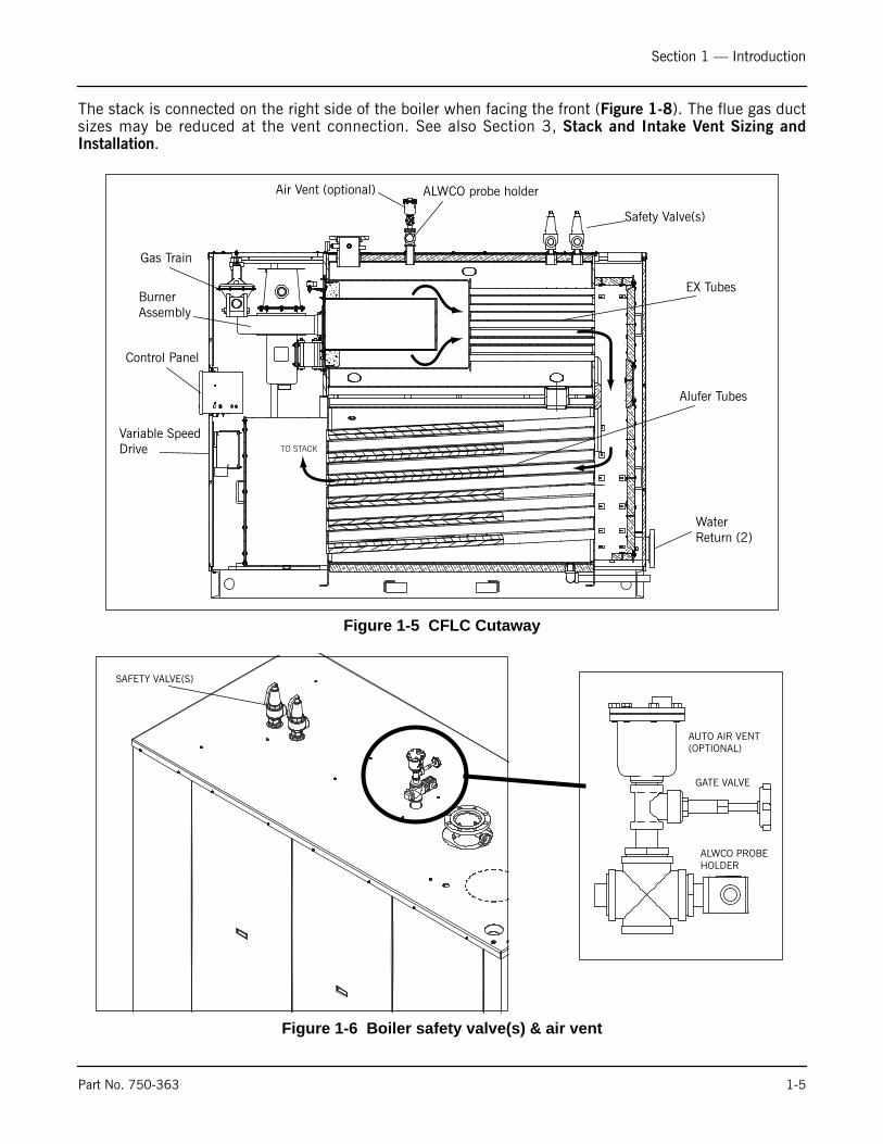
6. Component/Connection LocationsFigure 1-5 shows the CFLC component orientation and heat flowpath. The return water connections are at the lower vessel and thehot water outlet is at the top of the boiler.
Figure 1-6 shows the locations of the safety valve and air ventconnections. Figure 1-7 shows the location of the return watertemperature sensor.
Figure 1-3 Control panel interior
IGNITION TRANSFORMER
FALCON CONTROLLER, HYDRONICCONTROLLER, LWCO
TRANSFORMER, 115v/25v
TRANSFORMER, 460/230/208V PRI, 350VA, FUSED TOP
TERMINAL TRACKFUSE, BLOWER
Figure 1-4 VSD (lower front casing removed)
1-4 Part No. 750-363
Section 1 — Introduction
The stack is connected on the right side of the boiler when facing the front (Figure 1-8). The flue gas ductsizes may be reduced at the vent connection. See also Section 3, Stack and Intake Vent Sizing andInstallation.
Figure 1-5 CFLC Cutaway
Figure 1-6 Boiler safety valve(s) & air vent
TO STACK
Air Vent (optional) ALWCO probe holder
Safety Valve(s)
EX Tubes
Alufer Tubes
Control Panel
Variable Speed Drive
Gas Train
BurnerAssembly
Water Return (2)
ALWCO PROBEHOLDER
GATE VALVE
AUTO AIR VENT(OPTIONAL)
SAFETY VALVE(S)
Part No. 750-363 1-5

Section 1 — Introduction
Figure 1-7 Return temperature sensor (rear casing & insulation not shown)
Figure 1-8 Stack Outlet
STACK OUTLET
COMBUSTION AIR FILTER
W OUT
1-6 Part No. 750-363
Section 1 — Introduction
7. Optional EquipmentCertain project-specific options may have been supplied with the boiler if these options were specified atthe time of order entry. In addition, some options may have been provided (by others) that are not part ofCleaver-Brooks’ scope of supply. In either case, the Cleaver-Brooks authorized representative should beconsulted for project specifics.
These are the options that are available for the CFLC boiler from Cleaver-Brooks:
A. Condensate neutralization tank assembly - consists of neutralizing media, filter, and PVCcondensate holding tank. This assembly is further described in Chapter 2.
B. Outside air intake for direct vent combustion.C. Outdoor temperature sensor for outdoor reset, frost protection, and warm weather shutdown.D. Header temperature sensor for multiple boiler Lead/Lag operation.E. Alarm Horn for safety shutdown.F. Relays for output signal for burner on, fuel valve open.G. Stack Thermometer.H. Stack temperature limit-sensor.I. Auto air vent.J. Boiler drain valve.
For options not listed, consult your authorized CB representative.
Part No. 750-363 1-7

Section 1 — Introduction
1-8 Part No. 750-363

Section 2
Installation
Assembly . . . . . . . . . . . . . . . . . . . . . . . . . . . . . . . . . . . . . . . . . . . . 2-3Packaging . . . . . . . . . . . . . . . . . . . . . . . . . . . . . . . . . . . . . . . . . . 2-3Boiler placement . . . . . . . . . . . . . . . . . . . . . . . . . . . . . . . . . . . . . 2-3
Flue gas / combustion air connections . . . . . . . . . . . . . . . . . . . . . . . . 2-4Water treatment . . . . . . . . . . . . . . . . . . . . . . . . . . . . . . . . . . . . . . . 2-4Using glycol . . . . . . . . . . . . . . . . . . . . . . . . . . . . . . . . . . . . . . . . . . 2-5Boiler room . . . . . . . . . . . . . . . . . . . . . . . . . . . . . . . . . . . . . . . . . . . 2-7Gas connections . . . . . . . . . . . . . . . . . . . . . . . . . . . . . . . . . . . . . . . 2-8
General . . . . . . . . . . . . . . . . . . . . . . . . . . . . . . . . . . . . . . . . . . . . 2-8Gas train components . . . . . . . . . . . . . . . . . . . . . . . . . . . . . . . . 2-8Gas pressure requirements . . . . . . . . . . . . . . . . . . . . . . . . . . . . 2-6Gas Piping . . . . . . . . . . . . . . . . . . . . . . . . . . . . . . . . . . . . . . . . 2-9Gas supply pipe sizing . . . . . . . . . . . . . . . . . . . . . . . . . . . . . . 2-11Gas Header . . . . . . . . . . . . . . . . . . . . . . . . . . . . . . . . . . . . . . 2-13
Boiler water piping . . . . . . . . . . . . . . . . . . . . . . . . . . . . . . . . . . . . . 2-14General . . . . . . . . . . . . . . . . . . . . . . . . . . . . . . . . . . . . . . . . . . . 2-14
Safety valve . . . . . . . . . . . . . . . . . . . . . . . . . . . . . . . . . . . . . . 2-14Dual return design . . . . . . . . . . . . . . . . . . . . . . . . . . . . . . . . . 2-14Pressure drop curves . . . . . . . . . . . . . . . . . . . . . . . . . . . . . . . 2-15
Condensate removal and treatment . . . . . . . . . . . . . . . . . . . . . . . . . 2-17Condensate tank setup options . . . . . . . . . . . . . . . . . . . . . . . . . . 2-18
Electrical connections . . . . . . . . . . . . . . . . . . . . . . . . . . . . . . . . . . 2-20wiring diagram . . . . . . . . . . . . . . . . . . . . . . . . . . . . . . . . . . . . . . . 2-22
www.cleaverbrooks.com

Section 2 — Installation
Provisions for combustion and ventilation air mustbe in accordance with the National Fuel GasCode, ANSI Z223.1, or the CAN/CSA B149Installation Codes, or applicable provisions of thelocal building codes. Failure to follow this warningcould result in personal injury or death.
The boiler must be installed such that the gasignition system components are protected fromwater (dripping, spraying, rain, etc.) duringappliance operation and sevice. Failure to followthis warning could result in equipment failure.
Caution
The installation must conform to the require-ments of the authority having jurisdiction, or inthe absence of such requirements, to theNational Fuel Gas Code, ANSI Z223.1 and/orCAN/CSA B149 Installation Codes.
If an external electrical source is utilized, the boilerwhen installed must be electrically bonded toground in accordance with the requrements of theauthority having jurisdiction, or in the absence ofsuch requirements with the National ElectricalCode ANSI/NFPA 70 and/or the CanadianElectrical Code Part I CSA C22.1.
! Warning
! Warning! Warning
2-2 Part No. 750-363

Section 2 — Installation
A. ASSEMBLY
1. PackagingThe Cleaver-Brooks Model CFLC boiler is shipped fully assembled, ready for installation.
2. Boiler placementThe boiler or boilers should be mounted in accordance with Figure 2-1 below. Required front, rear, and sideclearances are shown.
NOTE
The boiler assemblies are intended for installation in accordance with the appropriate standards of the National Fire Protection Association and the building code recommended by the American Insurance Association. Local codes may differ. Installation should provide clearances to unprotected combustible material not less than those indicated in the following:Clearances to adjacent combustible construction not less than 36 inches from control panel front, 24 inches from sides, and 36 inches above and rear. The floor beneath these units may be combustible. In all cases, the flue pipe shall not pass through any floor or ceiling or any combustible wall or partition unless suitably guarded.
Figure 2-1 Clearance Required (inches)
Top Clearance = 36”
Part No. 750-363 2-3

Section 2 — Installation
B.FLUE GAS / COMBUSTION AIR CONNECTIONSThe flue gases from the Model CFLC boiler should be removed via a gas-tight, temperature and corrosionresistant flue gas pipeline. Only flue gas systems approved and tested by the relevant region or province areto be connected to the boiler. Refer to flue piping manufacturer for proper installation and sealinginstructions. See also Chapter 3 of this manual for combustion air and flue gas venting requirements.
C. WATER TREATMENTCleaver-Brooks ClearFire condensing boilers are suitable for heating systems without significant oxygenationcapacity. Systems with continuous oxygenation capacity due to unknown or unseen leaks must be equippedwith a system separation or pretreatment device.
Clean, soft water is generally the best heating medium for filling and make-up water in systems utilizing theModel CFLC. If the water available from the main system is not suitable for use, then demineralization and/or treatment with inhibitors is necessary. Treated filling and make-up water must be checked at least oncea year or more frequently if so specified in the application guidelines from the inhibitor manufacturer.
Those parts of the boiler in contact with water are manufactured with both ferrous materials and corrosion-resistant stainless steel. The chloride content of the heating water must not exceed 30 ppm and the pHlevel should be between 8.3 to 9.5 after six weeks of operation.
To maintain the boiler's efficiency and prevent overheating of the heating surfaces, the values in Table 2-1should not be exceeded. Water make-up during the lifetime of the boiler should not be greater than 3 timesthe system volume. A water meter should be installed on the feed line to monitor makeup water volume.
Following production of the pressure vessel, the interior surfaces are cleaned and therefore a pre-start boilout of the vessel is not needed. Should the system require boil out or cleaning after installation of the CFLC,take care that no particulate matter reaches the boiler during the cleaning process. A removable filter shouldbe used for this purpose.
D.USING GLYCOLThe Model CFLC boiler may be operated with a solution of glycol and water. Where glycols are added, thesystem must first be cleaned and flushed. Correct glycol selection and regular monitoring of the in-use
Note: Corrosion and sludge deposits in old systems must be removedprior to installation of a new boiler.
Table 2-1 Model CFLC Water ChemistryParameter Limit
pH 8.3 - 9.5Chloride 30 ppmNitrates 50 ppm
Sulphates 50 ppmOxygen 0.1 ppm
Specific Conductivity 3500 mmho/cmTotal Hardness <10 ppm
Table 2-2 Model CFLC Water Temperature Data (Non-Glycol)
Minimum inlet temp. 33oFMaximum operating temp. 230oFMaximum design temp. 250oF
2-4 Part No. 750-363

Section 2 — Installation
concentration and its stability is essential to ensure adequate, long-term freeze protection, includingprotection from the effects of glycol-derived corrosion resulting from glycol degradation.
Typically, ethylene glycol is used for freeze protection, but other alternatives exist, such as propylene glycol.Glycol reduces the water-side heat capacity (lower specific heat than 100% water) and can reduce theeffective heat transfer to the system. Because of this, design flow rates and pump selections should be sizedwith this in mind.
Generally, corrosion inhibitors are added to glycol systems. However, all glycols tend to oxidize over time inthe presence of oxygen, and when heated, form aldehydes, acids, and other oxidation products. Wheneverinadequate levels of water treatment buffers and corrosion inhibitors are used, the resulting water glycolmixture pH may be reduced to below 7.0 (frequently reaching 5) and acid corrosion results. Thus, whenpH levels drop below 7.0 due to glycol degradation the only alternative is to drain, flush, repassivate, andrefill with a new inhibited glycol solution.
The following recommendations should be adhered to in applying ClearFire model CFLC boilers to hydronicsystems using glycol:
1) Maximum allowable antifreeze proportion (% volume): 50% antifreeze (glycol)50% water
2) Glycol minimum temperature rating 300 deg F (149 deg C).3) The glycol concentration determines the maximum allowable firing rate and output of the boiler(s). Please refer
to the firing rate limitation and corresponding high fire speed settings vs. glycol% in the charts below.4) Maximum allowable boiler outlet/supply temperature: 200 deg F (93 deg C).5) Minimum water circulation through the boiler:
a) The minimum water circulation must be defined in such a way that the temperature differencebetween the boiler outlet/supply and inlet/return is a maximum of 40 deg F (22 deg C), defined as DT
(Delta T). A DT Limit algorithm should be enabled in the boiler controller.
b) Independent from the hydraulics of the heating system, constant water circulation through each boileris required while the boiler is operating (requires a dedicated boiler pump if in a primary/secondaryloop arrangement). Refer to table below for minimum boiler circulation rates.
6) Minimum over-pressure at the boiler:For outlet temperatures up to the maximum of 200 deg F (93 deg C), a minimum operating pressure of 30 psig(2.1 bar) is required.
7) pH level should be maintained between 8.3 and 9.5
Part No. 750-363 2-5

Section 2 — Installation
Glycol Application Guidelines — ClearFire Model CFLC
Minimum required boiler circulation rate (gpm) at maximum firing rateClearFireModel-Size
System ΔT (˚F) ΔT = 10˚ ΔT = 20˚ ΔT = 30˚ ΔT = 40˚
CFLC-4000 920 460 307 230CFLC-5000 1150 575 383 287CFLC-6000 1380 690 460 345CFLC-8000 1840 920 613 460CFLC-10000 2299 1150 766 575CFLC-12000 2759 1380 920 690
Notes/Limitations:1. Maximum firing rate determined by ClearFire CFLC - Glycol Firing Rate Limitation chart (below). Maximum high fire blower speed should be set according to chart.2. Glycol concentration limit of 25%-50%. Minimum required system operating pressure is 30 psig.3. Maximum system operating temperature of 200 ˚F. Maximum ΔT of 40˚.4. Circulation rates correlate with boiler output based on 92% nominal efficiency.5. Standard altitude (<2000' ASL). Contact C-B for high altitude applications.6. Pumps should be sized based on system design ΔT and minimum required flow rates.7. At minimum firing rate, the minimum circulation rate should correspond to the boiler's turndown.
2-6 Part No. 750-363
Section 2 — Installation
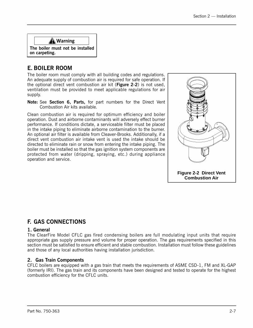
E. BOILER ROOMThe boiler room must comply with all building codes and regulations.An adequate supply of combustion air is required for safe operation. Ifthe optional direct vent combustion air kit (Figure 2-2) is not used,ventilation must be provided to meet applicable regulations for airsupply.
Note: See Section 6, Parts, for part numbers for the Direct VentCombustion Air kits available.
Clean combustion air is required for optimum efficiency and boileroperation. Dust and airborne contaminants will adversely effect burnerperformance. If conditions dictate, a serviceable filter must be placedin the intake piping to eliminate airborne contamination to the burner.An optional air filter is available from Cleaver-Brooks. Additionally, if adirect vent combustion air intake vent is used the intake should bedirected to eliminate rain or snow from entering the intake piping. Theboiler must be installed so that the gas ignition system components areprotected from water (dripping, spraying, etc.) during applianceoperation and service.
F. GAS CONNECTIONS
1. GeneralThe ClearFire Model CFLC gas fired condensing boilers are full modulating input units that requireappropriate gas supply pressure and volume for proper operation. The gas requirements specified in thissection must be satisfied to ensure efficient and stable combustion. Installation must follow these guidelinesand those of any local authorities having installation jurisdiction.
2. Gas Train ComponentsCFLC boilers are equipped with a gas train that meets the requirements of ASME CSD-1, FM and XL-GAP(formerly IRI). The gas train and its components have been designed and tested to operate for the highestcombustion efficiency for the CFLC units.
! Warning
The boiler must not be installedon carpeting.
Figure 2-2 Direct Vent Combustion Air
Part No. 750-363 2-7

Section 2 — Installation
3. Gas Pressure RequirementsFor proper and safe operation, each CFLC Series boiler requires a stable gas supply pressure. See Table 2-3 for pressure requirements. Refer also to APPENDIX D - GAS VALVE.
*Higher gas pressures will require an upstream high pressure step down regulator
Actual gas pressure should be measured when the burner is firing using a manometer at the upstream testport connection on the main gas valve. For a multiple unit installation, gas pressure should be set for asingle unit first, then the remaining units should be staged on to ensure that gas supply pressure drop isnot more than 1" w.c. and never below the required pressure. Fluctuating gas pressure readings could be
Table 2-3 Model CFLC Gas Pressure Requirements
Boiler Model
Minimum pressure required at gas train connection
Max. pressure*
4000 14” WC 1.2 PSI5000 14” WC 1.2 PSI6000 28” WC 2 PSI8000 28” WC 2 PSI10000 31” WC 2 PSI12000 31” WC 2 PSI
High PressureRegulator
Manual shutoffvalve (MSOV)
MSOV
RegulatingActuator
Gas valve bodyLow gas press.switch
High gas press.switch
Leak testcocks
TOP VIEW
(optional)
Figure 2-3 CFLC Gas Train (typical)
2-8 Part No. 750-363

Section 2 — Installation
indicative of a faulty supply regulator or improper gas train size to the boiler. Refer to tables 2-4 and 2-5for gas piping recommendations.
To measure pilot gas pressure, use the test port on the pilot solenoid valve.
4. Gas Piping
If a regulator is required, do not use a common regulator to regulate pressure for a multiple unit installation.Use one high pressure regulator for each CFLC boiler.
The regulator for each boiler must be installed outside the boiler enclosure with at least 2 feet of pipebetween the regulator and the boiler gas valve connection. The discharge range of the regulator must be ableto maintain gas pressures as noted in Table 2-3.
For buildings or boiler rooms with gas supply pressure exceeding 1.2 psi (CFLC 4000/5000) or 2 psi forCFLC 6000-12000 a "full lock-up" type regulator is required as well as overpressure protection (e.g. reliefvalve).
In addition to the regulator, a plug type or "butterball” type gas shutoff valve must be installed upstream ofthe regulator for use as a service valve. This is also required to provide positive shutoff and isolate the unitduring gas piping tests.
If necessary a strainer should be installed upstream of the regulator to remove debris from the gas supply.
Drip legs are required on any vertical piping at the gas supply to each boiler so that any dirt, weld slag, ordebris can deposit in the drip leg rather than into the boiler gas train. The bottom of the drip leg shouldremovable without disassembling any gas piping. The connected piping to the boiler should be supportedfrom pipe supports and not supported by the boiler gas train or the bottom of the drip leg.
All gas piping and components to the boiler gas train connection must comply with NFPA 54, local codes,and utility requirements as a minimum. Only gas approved fittings, valves, or pipe should be used. Standardindustry practice for gas piping is normally Schedule 40 black iron pipe and fittings.
Figure 2-4 Pilot train
VALVESOLENOID PILOT
COCKGAS SERVICE
Test Port
Part No. 750-363 2-9

Section 2 — Installation
Before starting the unit(s) all piping must be cleaned of all debris to prevent its entrance into the boiler gastrain. Piping should be tested as noted in NFPA 54 and the boiler must be isolated during any tests.
After initial startup, the inlet screen to the gas valve should be checked and cleaned of any debris buildupthat may have resulted from installation.
See Figure 2-5 for a typical piping configuration.
Figure 2-5 Gas Piping
The boiler and its individual shutoff valve must be disconnected from the gas supply piping system duringany pressure testing of that system at test pressures in excess of 1/2 psi (3.5 kPa).The boiler must be isolated from the gas supply piping system by closing its individual manual shutoffvalve during any pressure testing of the gas supply piping system at test pressures equal to or less than 1/2 psi (3.5 kPa).
! Caution
Same or larger than boiler gas connectionsize
Drip leg required for any vertical run ofpiping
As required
Gas header - size for boiler roomcapacity and to minimize pressure loss
As requiredTO GAS TRAIN
As required
2-10 Part No. 750-363

Section 2 — Installation
5. Gas Supply Pipe SizingFor proper operation of a single unit or a multiple unit installation, CB recommends that the gas piping besized to allow no more than 0.3" w.c. pressure drop from the source (gas header or utility meter) to the finalunit location. Higher supply pressure systems may allow for a greater pressure drop. In ALL cases, minimumsupply pressures must be met for proper operation of the boiler(s). The gas supplier (utility) should beconsulted to confirm that sufficient volume and normal pressure are provided to the building at thedischarge side of the gas meter or supply pipe.
For installations of new boilers into an existing building, gas pressure should be measured with amanometer to ensure sufficient pressure is available. A survey of all connected gas-using devices should bemade. If appliances other than the boiler or boilers are connected to the gas supply line, then adetermination must be made of how much flow volume (cfh) will be demanded at one time and the pressuredrop requirement when all appliances are firing.
The total length of gas piping and all fittings must be considered when sizing the gas piping. Total equivalentlength should be calculated from the utility meter or source to the final unit connection. As a minimumguideline, see gas piping Tables 2-4 and 2-5. The data in these tables is from the NFPA 54 source book,2006 edition.
To verify the input of each device that is connected to the gas piping, obtain the btu/hr input and divide thisinput by the calorific value of the gas that will be utilized. For instance, a unit with 4,000,000 btu/hr inputdivided by a gas calorific value of 1060 will result in a flow of 3774 cfh. The single boiler is approximately20 feet from the gas supply header source. And with a measured gas supply pressure of 10" w.c. we findfrom Table 2-4 that a supply pipe size of 3" should be used as a minimum.
Part No. 750-363 2-11

Section 2 — Installation
Table 2-4: Gas Line Capacity - Schedule 40 Metallic Pipe
Pipe SizeNominal 2-1/2" 3" 4"Actual I.D. 2.469" 3.068" 4.026"Length in feet **Maximum Capacity in Cubic Feet of Gas per Hour (cfh)10 4,860 8,580 17,50020 5,900 12,00030 9,66040 8,29050 7,33060 6,64070 6,11080 5,68090 5,330100 5,040125 4,460150 4,050175200**Fuel: Natural Gas**Inlet Pressure: Less than 2.0 psi**Pressure Drop: 0.30" w.c.
**Specific Gravity: 0.60
Table 2-5: Gas Line Capacity - Schedule 40 Metallic Pipe
Pipe SizeNominal 2" 2-1/2" 3" 4"Actual I.D. 2.067" 2.469" 3.068" 4.026"Length in feet **Maximum Capacity in Cubic Feet of Gas per Hour (cfh)10 4,020 6,400 11,300 23,10020 4,400 7,780 15,90030 6,250 12,70040 5,350 10,90050 4,740 9,60060 4,290 8,76070 8,05080 7,49090 7,030100 6,640125 5,890150 5,330175 4,910200 4,560**Fuel: Natural Gas**Inlet Pressure: Less than 2.0 psi**Pressure Drop: 0.50" w.c.
**Specific Gravity: 0.60
2-12 Part No. 750-363

Section 2 — Installation
6. Gas Header
Design of a single common gas header with individual takeoffs for a multiple unit installation isrecommended. Boiler gas manifold piping should be sized based on the volume requirements and lengthsbetween boilers and the fuel main header.
For installations with a mixed sized use, determine the flow of each unit and total the input. With the totalinput, determine length of run from the source and determine what size header will be needed for the flowof all units firing.
Figure 2-6 Gas header piping
Regulator
Header Pipe
MeterFrom
Gas Header Piping, Typical
Gas Strainer
Relief ValveSee Note 5
Manual Shut Off
See Note 1
NOTES:1. Dedicated gas pressure regulator required for each boiler if gas supply greater than max. pressure in Table 142. Refer to local fuel gas codes when applicable.3. Header to be sized for room capacity.4. Provision required for measuring gas supply pressure at boiler.5. Overpressure protection required if gas supply pressure > 5 psig.
Part No. 750-363 2-13

Section 2 — Installation
G.BOILER WATER PIPING
1. GeneralAll boiler hot water outlet and return piping is connected at the rear of the boiler. Piping is to be installedper local codes and regulations.The pipelines for the hot water outlet and return may be connected in theusual manner without removing the cladding elements. Unused connectors must be safely blanked off.
2. Safety valve
The pressure relief valve (safety valve) should be piped from the coupling on top of the boiler (see Figure2-7). Use pipe sealing compound and a flat sided wrench when securing the Safety relief valve. Do not usea pipe wrench and do not over tighten the relief valve. The safety valve must be mounted in a verticalposition so that discharge piping and code-required drains can be properly piped to prevent buildup of backpressure and accumulation of foreign material around the valve seat area. Apply only a moderate amountof pipe compound to male threads and avoid overtightening, which can distort the seats. Use only flat-jawed wrenches on the flats provided.
3. Dual return design
The Model CFLC features separate high and low temperature return water connections, allowing forcondensing performance within high temperature hydronic systems. With as little as 10% return water ator below 120 deg F, the Model CFLC will achieve condensing performance, with associated gains inefficiency.
Figure 2-7 Pressure relief valve piped to safe point of discharge
! Warning
Only properly certified personnel such as the safety valvemanufacturer’s certified representative should adjust or repair theboiler safety valve. Failure to follow this warning could result inserious personal injury or death.
2-14 Part No. 750-363

Section 2 — Installation
If using only a single (common) return, the low temperature connection should be used. The lowtemperature connection is on the left when facing the rear of the boiler.
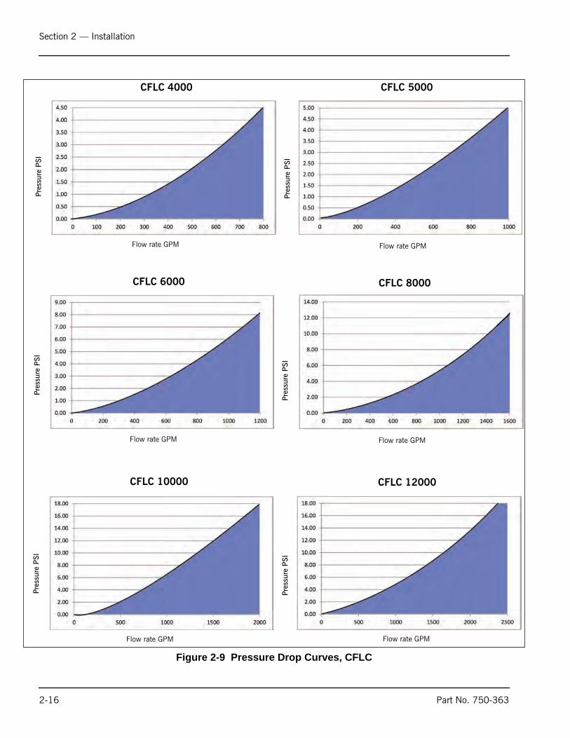
4. Pressure drop curves
The information in Figure 2-8 and in Tables 2-6 and 2-7 can help in determining pump requirements forModel CFLC installations.
Figure 2-8 Dual returns
Low Temp.Return
High Temp.
Return
Part No. 750-363 2-15
Section 2 — Installation
Figure 2-9 Pressure Drop Curves, CFLC
CFLC 4000 CFLC 5000
CFLC 6000 CFLC 8000
CFLC 10000 CFLC 12000
Pres
sure
PSI
Pres
sure
PSI
Pres
sure
PSI
Pres
sure
PSI
Pres
sure
PSI
Pres
sure
PSI
Flow rate GPM Flow rate GPM
Flow rate GPM Flow rate GPM
Flow rate GPM Flow rate GPM
2-16 Part No. 750-363

Section 2 — Installation
Table 2-6: CFLC flow rates
Table 2-7: CFLC flow rates (metric)
H.CONDENSATE REMOVAL AND TREATMENTThe condensate generated during normal boiler operation must be removed in accordance with local codesand regulations. The condensate can be piped to a local treatment system or run into the optionalcondensate treatment assembly.
The water trap must be filled with water prior to commissioning and checked or refilled at each requiredmaintenance interval.
System Temperature Drop Deg F
Boiler Size10 20 40 60 80 100
Flow Rate GPM
4000 752 376 188 125 94 75
5000 940 470 235 157 117 94
6000 1128 564 282 188 141 113
8000 1504 752 376 251 188 150
10000 1880 940 470 313 235 188
12000 2255 1128 564 376 282 226
Flow rates relative to temperature drop so as not to exceed boiler output.Based on 94% nominal efficiency.
System Temperature Drop Deg C
Boiler Size6 11 22 33 44 56
Flow Rate m3/hr
4000 171 85 43 28 21 17
5000 213 107 53 36 27 21
6000 256 128 64 43 32 26
8000 341 171 85 57 43 34
10000 427 213 107 71 53 43
12000 512 256 128 85 64 51
Flow rates relative to temperature drop so as not to exceed boiler output.Based on 94% nominal efficiency.
Part No. 750-363 2-17

Section 2 — Installation
Notice
The condensate occurring during operation in both the boiler and the flue gas pipeline has to be neutralized and pipedto a safe drain. The conditions for the discharge of condensates into public drain systems are determined by the localauthorities and municipalities.
Condensate leaving the boiler normally has a pH of 4-6. The responsible authority will inform you if a higherpH value is required for condensate piped to drain. The CFLC neutralization system contains the granulateNEUTRALAT, a natural compound which acts to increase the pH of the condensate flowing through it. Theneutralization system comprises the plastic neutralization tank with condensate inlet, granulate chamberand condensate outlet. The system is installed per Figure 2-11.
1. Condensate tank setup options
(1) Condensate direct to drain - The condensate is piped directly to a drain through the piping and watertrap supplied during installation (see Figure 2-10). Piping is to be a minimum of 1-1/4” NPT.
(2) Condensate to treatment tank - The condensate is held in a condensate tank near the boiler. Thecondensate is neutralized as it passes through the granular bed. The neutralized condensate is then pipedto the drain.
• To install the system, assemble the tank and fittings per instructions supplied with tank. Neutralization media are already installed in tank.
• Install the condensate tank cover and connect tank to boiler condensate discharge.
Pipe to an appropriate drain.
Figure 2-10 Condensate Piped Direct to Drain
Note: To ensure compliance with regulations, it is important to contact the responsible authorities priorto the planning and execution of the boiler installation. Condensate flow of 20 to 80 GPH can beexpected depending on boiler size and return water temperature.
COLD WATER RETURN
CONDENSATE DRAIN
DRAIN
WARM WATER RETURN
BOILER REAR
A CONDENSATE TRAPIS PIPED WITHIN THEBOILER.
2-18 Part No. 750-363

Section 2 — Installation
The neutralization media will require periodic replacement, to be determined by pH analysis of condensate.If condensate is too acidic (pH is below acceptable value) the neutralization media should be replaced.
The neutralizing media should be gently agitated periodically to ensure even distribution and to avoidchanneling of the condensate.
The number of condensate treatment tanks required depends on the total amount of condensate producedby the system. As a general rule, CB recommends one tank per boiler (sizes 4,000 - 8,000) and two tanks(sizes 10,000 - 12,000).
Figure 2-11 Condensate Treatment Tank
CFLC Model BTU/hr Max. Condensation
GPH4000 4,000,000 275000 5,000,000 346000 6,000,000 418000 8,000,000 54
10000 10,000,000 6812000 12,000,000 82
SIZES 4000-8000 SIZES 10,000-12,000
Part No. 750-363 2-19

Section 2 — Installation
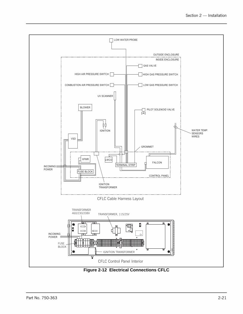
I. ELECTRICAL CONNECTIONSA qualified electrician or service technician must make the electrical connections to the boiler.
For specific information on your boiler electrical system refer to the Cleaver-Brooks wiring diagram providedwith the boiler.
Power is to be run from the top left corner of the boiler to the control panel (see Figure 2-12). AC power isto be connected to the incoming power terminals.
Note: The following temperature sensor cables should not be run near the high voltage incoming powerwiring.
• Hot water outlet temperature sensor.
• Hot water return temperature sensor.
• Stack temperature sensor (optional).
• Outdoor temperature sensor (optional).
! Warning
Ensure ignition cables are properly connected and not in direct contact with any sharp metal edges.
2-20 Part No. 750-363
Section 2 — Installation
Figure 2-12 Electrical Connections CFLC
BLOWER
CONTROL PANEL
LOW WATER PROBE
INSIDE ENCLOSURE
OUTSIDE ENCLOSURE
GAS VALVE
HIGH GAS PRESSURE SWITCH
LOW GAS PRESSURE SWITCH
IGNITION
UV SCANNER
HIGH AIR PRESSURE SWITCH
COMBUSTION AIR PRESSURE SWITCH
LWCO
TERMINAL STRIPFALCON
GROMMET
WATER TEMP.SENSORSWIRES
IGNITIONTRANSFORMER
PILOT SOLENOID VALVE
FUSE BLOCK
XFMR
VSD
INCOMINGPOWER
INCOMINGPOWER
CFLC Control Panel Interior
CFLC Cable Harness Layout
TRANSFORMER, 115/25V
TRANSFORMER460/230/208V
IGNITION TRANSFORMER
FUSEBLOCK
Part No. 750-363 2-21

Section 2 — Installation
J. WIRING DIAGRAM
Figure 2-13 CFLC Wiring Diagram, single fuel (typical)
Note: Wiring diagrams shown are examples only.Installations may vary. For specific installationsconsult the wiring diagram provided with the boiler.
2-22 Part No. 750-363

www.cleaverbrooks.com
Section 3Stack and Intake Vent Sizing and Installation
Venting Connections - General . . . . . . . . . . . . . . . . . . . . . . . . . . . . . . 3-2Appliance Categories . . . . . . . . . . . . . . . . . . . . . . . . . . . . . . . . . . 3-2Vent Stack . . . . . . . . . . . . . . . . . . . . . . . . . . . . . . . . . . . . . . . . . . 3-2Vent Terminal Location . . . . . . . . . . . . . . . . . . . . . . . . . . . . . . . . . 3-3Draft Tolerances . . . . . . . . . . . . . . . . . . . . . . . . . . . . . . . . . . . . . . 3-5
Vertical Venting / Inside Combustion Air . . . . . . . . . . . . . . . . . . . . . . . 3-6Vertical Venting / Direct Vent Combustion Air . . . . . . . . . . . . . . . . . . . 3-7Venting for multiple units . . . . . . . . . . . . . . . . . . . . . . . . . . . . . . . . . 3-8Combustion Air / Boiler Room Ventilation Requirements . . . . . . . . . . . 3-10
Air Supply - Unconfined Spaces . . . . . . . . . . . . . . . . . . . . . . . . . . 3-10Air Supply - Engineered Method . . . . . . . . . . . . . . . . . . . . . . . . . . 3-13

Section 3 — Stack and Intake Vent Sizing and Installation
Notice
A. VENTING CONNECTIONS - GENERAL
1. Appliance CategoriesProper installation of flue gas exhaust venting is critical for theefficient and safe operation of the CFLC boiler. The boiler ’sappliance category is a major factor determining venting systemdesign.
Definitions:
Boilers are divided into four categories based on the pressure andtemperature produced in the exhaust stack and the likelihood ofcondensate production in the vent.
• Category I. A boiler which operates with a non-positive vent static pressure and with a vent gas temperature that avoids excessive condensate production in the vent.
• Category II. A boiler which operates with a non-positive vent static pressure and with a vent gas temperature that may cause excessive condensate production in the vent.
• Category III. A boiler which operates with a positive vent pressure and with a vent gas temperature that avoids excessive condensate production in the vent.
• Category IV. A boiler which operates with a positive vent pressure and with a vent gas temperature that may cause excessive condensate production in the vent.
Depending on the application, the Model CFLC may be consideredCategory II, III, or IV. The specifying engineer should dictate flueventing as appropriate to the installation.
For additional information on boilercategorization, see appropriateANSI Z21 Standard and the latestedition Standard of National FuelGas Code or in Canada, the latestedition of CSA Standard B149Installation Code for Gas BurningAppliances and Equipment, orapplicable provisions of localbuilding codes.
Notice
During winter months check the vent cap and make sure noblockage occurs from build up of snow. Condensate can freeze onthe vent cap. Frozen condensate on the vent cap can result in ablocked flue condition.
2. Vent StackThe vent should be supported to maintain proper clearances fromcombustible materials.
! Warning
Contact the manufacturer of the vent material if there is anyquestion about the boiler categorization and suitability of a ventmaterial for application on a Category II, III or IV vent system.Using improper venting materials can result in personal injury,death or property damage.
3-2 Part No. 750-363

Section 3 — Stack and Intake Vent Sizing and Installation
Use insulated vent pipe spacers where the vent passes throughcombustible roofs and walls.
Vent material should be appropriate for the Appliance Category.Application-specific information will further determine the materialselected.
3. Vent Terminal LocationGive special attention to the location of the vent termination to avoidpossibility of property damage or personal injury.
1. Combustion gases can form a white vapor plume in the winter. The plume could obstruct a window view if the termination is installed in close proximity to windows.
2. Prevailing winds could cause freezing of condensate and water/ice buildup on building, plants or roof.
3. The bottom of the vent terminal and the air intake shall belocated at least 24 inches above grade, including normal snowline.
4. Un-insulated single-wall metal vent pipe shall not be usedoutside in cold climates for venting combustion gas.
5. Through-the-wall vents for Category II and IV appliances andnon-categorized condensing appliances shall not terminate overpublic walkways or over an area where condensate or vaporcould create a nuisance or hazard or could be detrimental to theoperation of other equipment. Where local experience indicatesthat condensate is a problem with Category III appliances, thisprovision shall also apply.
6. Locate and guard vent termination to prevent accidental contactby people and pets.
7. DO NOT terminate vent in window well, alcove, stairwell or otherrecessed area, unless previously approved by local authority.
8. DO NOT terminate above any door, window, or gravity air intake.Condensate can freeze causing ice formations.
9. Locate or guard vent to prevent condensate from damagingexterior finishes. Use a 2' x 2' rust resistant sheet metal backingplate against brick or masonry surfaces.
10. DO NOT extend exposed stack pipe outside of building. Inwinter conditions condensate could freeze and block stackpipe.
U.S. Installations- Refer to latest edition of the National Fuel GasCode.
Part No. 750-363 3-3

Section 3 — Stack and Intake Vent Sizing and Installation
Vent termination requirements are as follows: 1. Vent must terminate at least four (4) feet below, four (4) feet
horizontally, or one (1) foot above any door, window or gravity air inlet to the building.
2. The vent must not be less than seven (7) feet above grade whenlocated adjacent to public walkways.
3. Terminate vent at least three (3) feet above any forced air inletlocated within ten (10) feet.
4. Vent must terminate at least four (4) feet horizontally, and in nocase above or below unless four (4) feet horizontal distance ismaintained, from electric meters, gas meters, regulators, andrelief equipment.
5. Terminate vent at least six (6) feet away from adjacent walls. 6. DO NOT terminate vent closer than five (5) feet below roof
overhang.Canada Installations- Refer to the latest edition of CAN/CSA-B149.1 and B149.2
A vent shall not terminate:
1. Directly above a paved sidewalk or driveway which is located between two single family dwellings and serves both dwellings.
2. Less than 7 ft. (2.13m) above a paved sidewalk or paveddriveway located on public property.
3. Within 6 ft. (1.8m) of a mechanical air supply inlet to anybuilding.
4. Above a meter/regulator assembly within 3 ft. (900mm)horizontally of the vertical center-line of the regulator.
5. Within 6 ft. (1.8m) if any gas service regulator vent outlet. 6. Less than 1 ft. (300mm) above grade level. 7. Within 3 ft. (1m) of a window or door which can be opened in
any building, any non-mechanical air supply inlet to any buildingto the combustion air inlet of any other appliance.
8. Underneath a verandah, porch or deck, unless: • The verandah, porch or deck is fully open on a minimum
of two sides beneath the floor.
• The distance between the top of the vent termination and the underside of the verandah, porch or deck is greater than 1 ft. (30cm)
Note: For direct vent installations where the air is piped infrom outside, a protective screen on the air inlettermination elbow must be used to act as an inletscreen.
! Warning
Examine the venting system at least once a year. Check all jointsand vent pipe connections for tightness, corrosion or deterioration.
3-4 Part No. 750-363

Section 3 — Stack and Intake Vent Sizing and Installation
! Caution
Follow items listed below to avoid personal injury or propertydamage.
• Cut nonmetallic vent pipe with fine-toothed hacksaw (34 teeth per inch).
• Do not use nonmetallic vent pipe or fittings that are cracked or damaged.
• Do not use nonmetallic vent fittings if they are cut or altered.• Do not drill holes, or use screws or rivets, in nonmetallic vent pipe
or fittings.
4. Draft Tolerances
Maximum allowed pressure at vent connection is plus or minus 0.25inches WC.
Recommended maximum design pressure at vent connection is 0.10inches WC.
Venting Installation Tips
Support piping:• Horizontal runs- at least every five (5) feet.• Vertical runs - use braces.• Under or near elbows
Part No. 750-363 3-5

Section 3 — Stack and Intake Vent Sizing and Installation
B.VERTICAL VENTING / INSIDE COMBUSTION AIR
These installations utilize the boiler-mounted blower to vent thecombustion products to the outside. Combustion air is taken frominside the room and the vent is installed vertically through the roofto the outside. Adequate combustion and ventilation air must besupplied to the boiler room in accordance with the National FuelGas Code or, in Canada, the latest edition of CAN/CSA-B 149.1 and149.2 Installation Code for Gas Burning Appliances andEquipment.
To prevent accumulation of condensation in the vent, it is requiredto install the horizontal portion of vent with a slight slope of at least1/4” per foot of horizontal run, pitched either back to the boiler orto a low point equipped with suitable condensate trap and drain.
Figure 3-1 Vertical Stack with Inside Combustion Air
Flue Gas Vent
24"Minimum
10'-0" or Less
48"Minimum
Termination
3-6 Part No. 750-363

Section 3 — Stack and Intake Vent Sizing and Installation
! Warning
No substitutions of flue pipe or vent cap material are allowed.Such substitutions would jeopardize the safety and health ofinhabitants.
C. VERTICAL VENTING / DIRECT VENT COMBUSTION AIR
These installations utilize the boiler-mounted blower to drawcombustion air from outside and vent combustion products to theoutside.
To prevent accumulation of condensation in the vent, it is requiredto install the horizontal portion of vent with a slight slope of at least1/4” per foot of horizontal run, pitched either back to the boiler orto a low point equipped with suitable condensate trap and drain.
Figure 3-2 Vertical Stack with Direct Vent Combustion Air
Vent TerminationAir Intake (w/Screen)
48" Minimum48" Minimum
12" Minimumabove roofor snow line
Vent Termination
Air Intake (w/Screen)
48" Minimum
12" Minimumabove parapetor snow line
36" Minimumabove intak
24" Minimum
With parapet wall
Part No. 750-363 3-7
Section 3 — Stack and Intake Vent Sizing and Installation
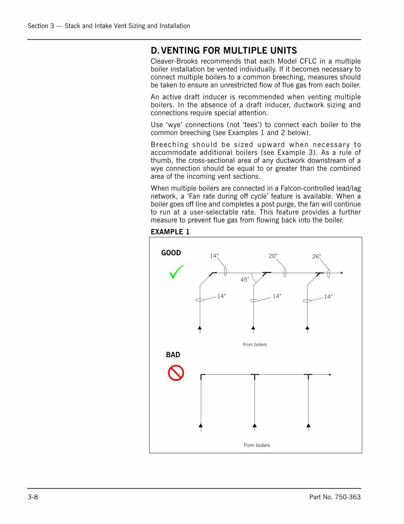
D.VENTING FOR MULTIPLE UNITSCleaver-Brooks recommends that each Model CFLC in a multipleboiler installation be vented individually. If it becomes necessary toconnect multiple boilers to a common breeching, measures shouldbe taken to ensure an unrestricted flow of flue gas from each boiler.
An active draft inducer is recommended when venting multipleboilers. In the absence of a draft inducer, ductwork sizing andconnections require special attention.
Use ‘wye’ connections (not ‘tees’) to connect each boiler to thecommon breeching (see Examples 1 and 2 below).
Breech ing shou ld be s i zed upward when necessar y toaccommodate additional boilers (see Example 3). As a rule ofthumb, the cross-sectional area of any ductwork downstream of awye connection should be equal to or greater than the combinedarea of the incoming vent sections.
When multiple boilers are connected in a Falcon-controlled lead/lagnetwork, a ‘Fan rate during off cycle’ feature is available. When aboiler goes off line and completes a post purge, the fan will continueto run at a user-selectable rate. This feature provides a furthermeasure to prevent flue gas from flowing back into the boiler.
EXAMPLE 1
�
From boilers
45o
14” 20” 26”
14” 14” 14”
�
From boilers
GOOD
BAD
3-8 Part No. 750-363

Section 3 — Stack and Intake Vent Sizing and Installation
EXAMPLE 2
EXAMPLE 3
�
From boilers
14”
20”
45o
14”
�
From boilers
GOOD
BAD
14”
14” 14” 14”
From Boilers
14” 14”
�16” 24” 30”
16” 16” 16”
From Boilers
�
45o
14” 20” 26”
14” 14” 14”
�
From boilers
GOOD
BAD
GOOD
Part No. 750-363 3-9

Section 3 — Stack and Intake Vent Sizing and Installation
E. COMBUSTI0N AIR/BOILER ROOM VENTILATION REQUIREMENTS
The boiler(s) must be supplied with adequate quantities ofuncontaminated air to support proper combustion and equipmentventilation. Air shall be free of chlorides, halogens, fluorocarbons,construction dust or other contaminants that are detrimental to theburner/boiler. If these contaminants are present, we recommend theuse of direct vent combustion provided the outside air source isuncontaminated.
Combustion air can be supplied by means of conventional venting,where combustion air is drawn from the area immediatelysurrounding the boiler (boiler room must be positive pressure), orwith direct vent (direct vent combustion) where air is drawn directlyfrom the outside. All installations must comply with local Codes andwith NFPA 54 (the National Fuel Gas Code - NFGC) for the U.S. andfor Canada, CAN/CGA B 149.1 and B 149.2.
Note: A boiler room exhaust fan is not recommended as this type of device can cause a negative pressure in the boiler room if using a conventional air intake.
In accordance with NFPA54, the required volume of indoor air shallbe determined in accordance with the "Standard Method" or "KnownAir Infiltration Rate Method. Where the air infiltration rate is knownto be less than 0.40 Air Changes per Hour, the Known Air InfiltrationRate Method shall be used (see Section 8.3 in the NFPA54Handbook for additional information).
1. Air Supply - Unconfined Spaces (For U.S. Installations Only)
A. All Air From Inside the Building - If all combustion air isdrawn from inside the building (the mechanical equipmentroom does not receive air from outside via louvers or ventopenings and the boiler is not equipped with direct ventcombustion) and the boiler is located in an unconfinedspace, use the following guidelines:
1. The mechanical equipment room must be provided with two permanent openings linked directly with additional room (s) of sufficient volume so that the combined volume of all spaces meet the criteria for an unconfined space. Note: An "unconfined space" is defined as a space whose volume is more than 50 cubic feet per 1,000 Btu per hour of aggregate input rating of all appliances installed in that space.
2. Each opening must have a minimum free area of one square inch per 1,000 Btu per hour of the total input rating of all gas utilizing equipment in the mechanical room.
3-10 Part No. 750-363

Section 3 — Stack and Intake Vent Sizing and Installation
3. One opening must terminate within twelve inches of the top, and one opening must terminate within twelve inches of the bottom of the room.
4. Refer to the NFGC, Section 8.3 for additional information.
B. All Air From Outdoors - If all combustion air will be received from outside the building (themechanical room equipment is linked with the outdoors), the following methods can be used:
1. Two Opening Method - The mechanical equipment room must be provided with two permanent openings, one terminating within twelve inches from the top, and one opening terminating within twelve inches of the bottom of the room.
2. The openings must be linked directly (Figure 3-5) or by ducts (Figure 3-6) with the outdoors.
3. Each opening must have a minimum free area of one square inch per 4,000 Btu per hour of total input rating of all equipment in the room, when the opening is directly linked to the outdoors or through vertical ducts.
4. The minimum free area required for horizontal ducts is one square inch per 2,000 Btu per hour of total input rating of all the equipment in the room.
Figure 3-5 Two Opening Outside Wall Method
GASVENT
WATERHEATER
GASVENT
INTERIOR WALL
FRESH AIR OPENING
FRESH AIR OPENING
12" MINIMUM
12" MINIMUM
CLEARFIREBOILER
Part No. 750-363 3-11
Section 3 — Stack and Intake Vent Sizing and Installation
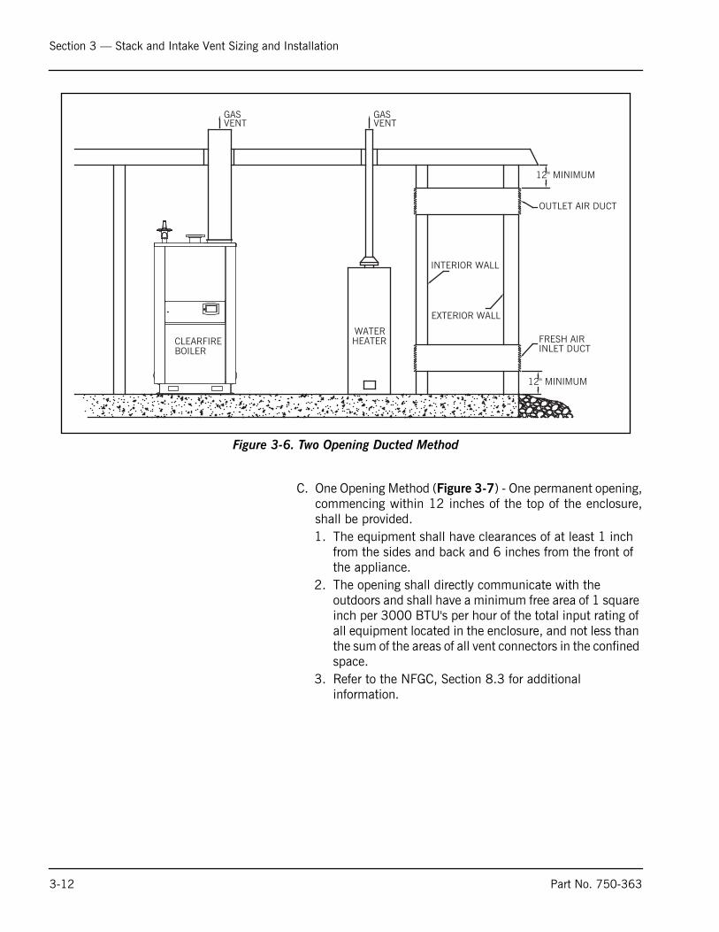
Figure 3-6. Two Opening Ducted Method
C. One Opening Method (Figure 3-7) - One permanent opening,commencing within 12 inches of the top of the enclosure,shall be provided. 1. The equipment shall have clearances of at least 1 inch
from the sides and back and 6 inches from the front of the appliance.
2. The opening shall directly communicate with the outdoors and shall have a minimum free area of 1 square inch per 3000 BTU's per hour of the total input rating of all equipment located in the enclosure, and not less than the sum of the areas of all vent connectors in the confined space.
3. Refer to the NFGC, Section 8.3 for additional information.
GASVENT
CLEARFIREBOILER
WATERHEATER
GASVENT
EXTERIOR WALL
INTERIOR WALL
FRESH AIRINLET DUCT
OUTLET AIR DUCT
12" MINIMUM
12" MINIMUM
3-12 Part No. 750-363

Section 3 — Stack and Intake Vent Sizing and Installation
Figure 3-7. One Opening Method
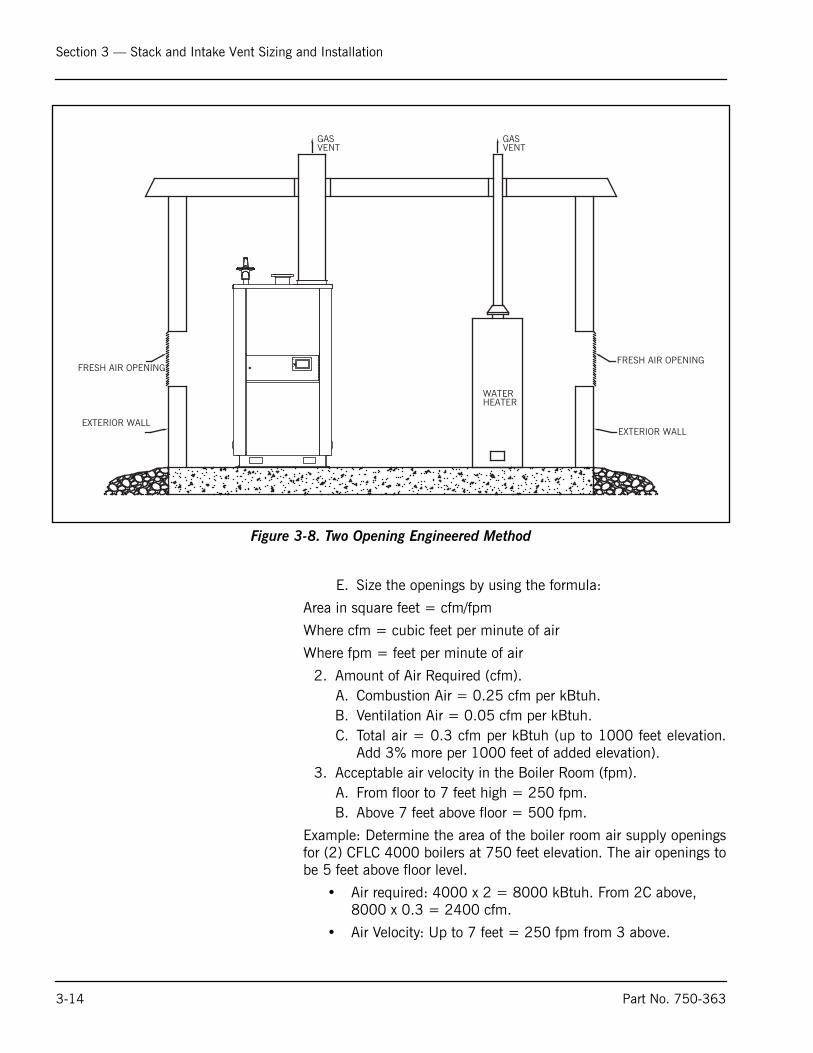
2. Air Supply - Engineered MethodWhen determining boiler room air requirements for an unconfinedspace, the size of the room, airflow, and velocity of air must bereviewed as follows:
1. Size (area) and location of air supply openings in the boiler room.A. Two permanent air supply openings in the outer walls of the
boiler room are recommended. Locate one at each end of theboiler room, preferably below a height of 7 feet. This allowsair to sweep the length of the boiler. See Figure 3-8.
B. Air supply openings can be louvered for weather protection,but they should not be covered with fine mesh wire, as thistype of covering has poor air flow qualities and is subject toclogging with dirt and dust.
C. A vent fan in the boiler room is not recommended, as it couldcreate a slight vacuum under certain conditions and causevariations in the quantity of combustion air. This can resultin unsafe burner performance.
D. Under no condition should the total area of the air supplyopenings be less than one square foot.
GASVENT
WATERHEATER
GASVENT
EXTERIOR WALL
FRESH AIR OPENING
12" MINIMUM
Part No. 750-363 3-13
Section 3 — Stack and Intake Vent Sizing and Installation
Figure 3-8. Two Opening Engineered Method
E. Size the openings by using the formula:
Area in square feet = cfm/fpm
Where cfm = cubic feet per minute of air
Where fpm = feet per minute of air
2. Amount of Air Required (cfm).A. Combustion Air = 0.25 cfm per kBtuh.B. Ventilation Air = 0.05 cfm per kBtuh. C. Total air = 0.3 cfm per kBtuh (up to 1000 feet elevation.
Add 3% more per 1000 feet of added elevation).3. Acceptable air velocity in the Boiler Room (fpm).
A. From floor to 7 feet high = 250 fpm.B. Above 7 feet above floor = 500 fpm.
Example: Determine the area of the boiler room air supply openingsfor (2) CFLC 4000 boilers at 750 feet elevation. The air openings tobe 5 feet above floor level.
• Air required: 4000 x 2 = 8000 kBtuh. From 2C above, 8000 x 0.3 = 2400 cfm.
• Air Velocity: Up to 7 feet = 250 fpm from 3 above.
GASVENT
WATERHEATER
GASVENT
EXTERIOR WALL
FRESH AIR OPENING
EXTERIOR WALL
FRESH AIR OPENING
3-14 Part No. 750-363

Section 3 — Stack and Intake Vent Sizing and Installation
• Area required: Area = cfm/fpm = 2400/250 = 9.6 square feet total.
• Area/Opening: 9.6/2 = 4.8 sq-ft/opening (2 required).
Notice
Consult local codes, which may supersede these requirements.
Direct Vent Combustion
If combustion air will be drawn directly from the outside by means ofa duct connected to the burner air intake, use the following as aguide:
1. Install combustion air vent (direct vent combustion) in accordance with the boiler's Operating and Maintenance manual.
2. Provide for adequate ventilation of the boiler room or mechanical equipment room.
3. In cold climates, and to mitigate potential freeze-up of the intake pipe, it is highly recommended that a motorized sealed damper be used to prevent the circulation of cold air through the boiler during non-operating hours.
4. Refer to Figure 3-2 and Figure 3-4 for suggested piping of direct vent combustion installations. Figure 3-9 shows the optional direct vent combustion kit providing easy adaptation of the contractor supplied air duct to boiler connection. Refer to Table 3-2 for sizing the direct vent combustion air pipe.
Figure 3-9. Optional Direct Vent Combustion Kit
Note: Direct vent ductwork should be securely attached to theboiler casing. No weight should be supported by theventuri. Venting should be installed to allow easydisconnection for burner service. For best results, theCleaver-Brooks direct vent kit is recommended. SeeTable 3-2 for kit part numbers.
Part No. 750-363 3-15

Section 3 — Stack and Intake Vent Sizing and Installation
3-16 Part No. 750-363

www.cleaverbrooks.com
Section 48
Section 4Commissioning
Operating Conditions . . . . . . . . . . . . . . . . . . . . . . . . . . . . . . . . . . . . 4-2Filling Boiler . . . . . . . . . . . . . . . . . . . . . . . . . . . . . . . . . . . . . . . . . . 4-2Control Setpoints . . . . . . . . . . . . . . . . . . . . . . . . . . . . . . . . . . . . . . . 4-2Model CFLC Boiler / Burner Controller . . . . . . . . . . . . . . . . . . . . . . . . 4-3Falcon Display/Operator Interface . . . . . . . . . . . . . . . . . . . . . . . . . . . 4-4Controller Configuration . . . . . . . . . . . . . . . . . . . . . . . . . . . . . . . . . . 4-7Burner Sequence . . . . . . . . . . . . . . . . . . . . . . . . . . . . . . . . . . . . . . 4-18Fan Speed Settings . . . . . . . . . . . . . . . . . . . . . . . . . . . . . . . . . . . . 4-19Initial start-up procedure . . . . . . . . . . . . . . . . . . . . . . . . . . . . . . . . 4-19Post start-up checkout procedure . . . . . . . . . . . . . . . . . . . . . . . . . . 4-26Falcon Control Functions and Customer Interface . . . . . . . . . . . . . . . 4-26
The boiler and its gas connection must beleak tested before placing the boiler inoperation.
! Warning

Section 4 — Commissioning
A. OPERATING CONDITIONS• The installation site should be as free as possible from vibration, dust, and corrosive media
• The controllers should be located as far as possible from sources of electromagnetic fields, such as frequency converters or high-voltage ignition transformers
• Control panel must be connected to earth ground.
• Refer to Section 3 in this manual for combustion air requirements.
B.FILLING BOILERFill the boiler and/or hydronic system. Water should be circulated through the system to allow entrappedair to escape at appropriate air venting provisions. Check to ensure that no leaks appear at any pipeconnections and correct if water leaks are noticed. When no air remains in the boiler, it will be possible toreset the low water cutoff. If the low water cutoff can not be reset, it is likely that some air remains in theboiler.
C. CONTROL SETPOINTS
Preliminary settings of the burner/boiler safety controls are necessary for the initial starting of the boiler.After the burner has been properly set, minor adjustments to these controls may be necessary for theparticular installation. For initial starting, set the following controls accordingly:
1. Combustion Air Proving Switch - Set the dial @ minimum.2. Low Gas Pressure Switch - Set the dial @ minimum.3. High Gas Pressure Switch - Set the dial @ maximum.4. High Air Pressure Switch - Set the dial @ maximum.Depress all manual reset buttons for all controls prior to starting.
Boiler room ambient conditions
Relative humidity < 85% non-condensingAmbient temperature range 0 oC to 50 oC / 32oF to 122oFStorage temperature range -40 oC to 60 oC / -40oF to 140oFCombustion air temperature 0 oC to 50 oC / 32oF to 122oF
! WarningWhen us ing d i r ec t ven tcombustion in cold climates,special care must be taken toobse r ve combus t i on a i rtemperature limits. Failure tofollow this precaution may leadto equipment damage or unsafeoperation.
4-2 Part No. 750-363

Section 4 — Commissioning
D.MODEL CFLC BOILER / BURNER CONTROLLER
The Model CFLC boiler uses the Falcon hydronic boilercontrol system. Primary controller functions include:
• Flame supervision• Burner sequencing• Heating/modulation control• Hot water system pump control• High Limit temperature control
• Thermowell-mounted NTC temperature sensors to provide measured process variable signals to the controller.
Additional features include:
• User-friendly touchscreen interface• Modbus communication capability• Alarm/lockout messaging with history (last 15 messages)• Annunciation• Outdoor reset• Central Heating and Domestic Hot Water loop control• Password protection of configurable parameters• Time of Day (dual setpoint) control
• High Stack Temperature limit• Remote reset• Lead/Lag sequencing• (3) configurable pump relays• Remote modulation/remote setpoint• Frost protection
Figure 4-2 Controller status LEDs and reset button
Figure 4-1 Opening control panel
Part No. 750-363 4-3

Section 4 — Commissioning
Please review the tables within this Commissioning section to familiarize yourself with the functions andparameters of the Controller. Also see Appendices A and B for details on control configuration and operation.
E. FALCON DISPLAY/OPERATOR INTERFACEThe Falcon display/operator interface is mounted at the left side of the control panel for convenient accessto all operating controls.
1. Home PageApply power to the boiler. The Home page will appear on the Falcon display.
Each Falcon in the hydronic system is represented on the Home page by an icon and name.
2. Status PagePressing the Falcon icon takes the user to the Status page, which summarizes boiler status and allowsnavigation to the configuration, operational, and diagnostic areas of the Falcon interface.
! WarningThe Model CFLC is factory tested. Nevertheless, all burner safetycontrols should be checked upon installation, prior to initial firing.Failure to verify burner control functioning could result in severebodily injury or death.
Figure 4-3 Falcon Display/Operator Interface
4-4 Part No. 750-363

Section 4 — Commissioning
The Demand display will show one of the following:
Burner enable offOff (burner switch on but no demand)Central HeatDomestic Hot Water (if configured)
Burner state shows the currently active step in the burner operating sequence.
The central portion of the display can be toggled between the following:
Pumps shows the on/off status of boiler and system pumps.Modulation shows fan speed RPM settings for Demand, Limited, and Override ratesSetpoints shows the ON, Modulation, and OFF temperature setpoints.
3. Operation PageThe operation page (Figure 4-4) displays the Falcon running operation, including setpoint and firing ratevalues. From this page the user can change setpoints, manually control the boiler’s firing rate, manuallyturn pumps on, view annunciation information, and switch between heating loops (Central Heat andDomestic Hot Water). If a password is required to change any of the settings on this page, the user canpress the Login button to enter the password.
The burner is enabled from this page by turning the <Burner switch> screen button ON.
Home page Status page
Part No. 750-363 4-5

Section 4 — Commissioning
Figure 4-5 Falcon Display/Interface page flow
4. Lockouts, Holds, and AlertsTo assist in monitoring boiler operation, the Falcon control system employs messages of three types:Lockouts, Holds, and Alerts.
• Lockouts and Holds indicate interruptions in boiler operation, whether occurring as part of the normal operating sequence or due to an abnormal condition. Lockouts require a manual reset to continue operation, while Holds do not. A Hold will automatically clear when the hold condition is removed or satisfied.
Figure 4-4 Operation Page
4-6 Part No. 750-363

Section 4 — Commissioning
The most recent Lockouts are stored in Falcon memory and may be accessed through the Lockout History.Holds are not logged in memory.
Note: Before attempting to restart the boiler after a Lockout, identify and correct the Lockout condition.
• Alerts indicate conditions or events which, while not preventing boiler operation, may nevertheless be of interest in evaluating boiler performance or operating conditions. Examples include certain operator actions, out-of-range configuration data, controller internal status reports (e.g. timers, counters, memory read/write activity), and recycle events. Alerts require no operator acknowledgment and are for informational purposes only.
The most recently occurring message (Lockout, Hold, or Alert) is displayed in the alarm banner on theStatus screen (see Figure 4-6). Press this banner to access the Alert or Lockout History, where a list of themost recently occurring Alerts/Lockouts can be viewed.
To obtain more information for a particular message, press that item in the respective history list. For Alerts,burner cycle and hours of operation at the time of occurrence will be displayed. For Lockouts, in additionto cycle and hours the screen will show on/off status of all interlocks at the time of the lockout. Thisinformation can be used to help pinpoint the cause of a particular Lockout.
See also Section 5 - Service and Maintenance, Subsection E - Troubleshooting.
F. CONTROLLER CONFIGURATIONThe Falcon controller should be factory configured for the specific CFLC boiler model. Prior to starting theboiler, verify that the factory default settings are correct for your application. Please refer to CB defaultsettings, Table 4-1, and make any changes at this time if needed.
Falcon configuration is organized into the following functional groups:
• System Identification & Access• CH - Central Heat ConfigurCation• Outdoor Reset Configuration• DHW - Domestic Hot Water Configuration• Modulation Configuration• Pump Configuration• Statistics Configuration• High Limits• Stack Limit• Other Limits• Anti-condensation Configuration• Frost Protection Configuration• Annunciation Configuration• Burner Control Interlocks
Figure 4-6 Alarm Banner
Alarm Banner
Part No. 750-363 4-7

Section 4 — Commissioning
• Burner Control Timings & Rates• Burner Control Ignition• Burner Control Flame Failure• System Configuration• Fan Configuration• Lead Lag Configuration
Table 4-1 CFLC Falcon Parameters Parameter Group Parameter Name Access* Min
rangeDefault Setting Max.
RangeParameter
UnitsModbus
Register (dec)
System ID & Access Boiler name Service BOILER 1 183System ID & Access Installation data Service SERIAL NUMBER 184System ID & Access OEM identification Read
OnlyFALCON 833-04097 185
System ID & Access Installer Password Service 9220 190System ID & Access Factory Data Read
Only191
System ID & Access Modbus Address Service 0 1 250Central Heat Configuration CH enable User Enabled 208Central Heat Configuration CH demand switch Service B:STAT terminal 209Central Heat Configuration CH modulation sensor Service A:Modulation from Outlet (S3S4)
sensor210
Central Heat Configuration CH setpoint User 130 150 230 oF 211Central Heat Configuration CH TOD setpoint User 130 130 230 oF 212Central Heat Configuration CH on hysteresis Service 5 60 oF 213Central Heat Configuration CH off hysteresis Service 15 60 oF 214Central Heat Configuration CH outdoor reset enable Service Disabled 215Central Heat Configuration CH P gain Service 25 216Central Heat Configuration CH I gain Service 10 217Central Heat Configuration CH D gain Service 0 218Central Heat Configuration CH hysteresis step time Service 0m 0s mmm ss 219Central Heat Configuration CH setpoint source Service A:Local setpoint is used 578Central Heat Configuration CH modulation rate source User A:Local modulation (PID) is used 580Central Heat Configuration CH has priority over LL Service No/False/Off 582Central Heat Configuration CH 4 mA water temperature Service 130 194 oF 583Central Heat Configuration CH 20 mA water temperature Service 210 230 oF 584Outdoor Reset Configuration CH ODR max outdoor temperature Service 80 oF 512Outdoor Reset Configuration CH ODR min outdoor temperature Service 0 oF 513Outdoor Reset Configuration CH ODR low water temperature Service 80 oF 514Outdoor Reset Configuration CH ODR boost time Service 30m 0s mmm ss 515Outdoor Reset Configuration CH ODR boost maximum off point Service 180 230 oF 516Outdoor Reset Configuration CH ODR boost step Service 0°F (0°C) oF 522Outdoor Reset Configuration Minimum boiler water
temperatureService 130 130 oF 526
Domestic HW Configuration DHW enable User Disabled 448Domestic HW Configuration DHW demand switch User A:Modulation sensor only 449Domestic HW Configuration DHW has priority over CH Service Yes/True/On 450Domestic HW Configuration DHW has priority over LL Service Yes/True/On 451Domestic HW Configuration DHW priority override time Service 30m 0s mmm ss 452Domestic HW Configuration DHW setpoint User 130 180 230 oF 453Domestic HW Configuration DHW TOD setpoint User 130 130 230 oF 454Domestic HW Configuration DHW on hysteresis Service 5 80 oF 455Domestic HW Configuration DHW off hysteresis Service 15 80 oF 456Domestic HW Configuration DHW P gain Service 25 457Domestic HW Configuration DHW I gain Service 10 458Domestic HW Configuration DHW D gain Service 0 459Domestic HW Configuration DHW hysteresis step time Service 1m 0s mmm ss 460Domestic HW Configuration DHW modulation sensor Service F:Auto Mod from DHW (S6)or
Outlet (S3S4)461
Domestic HW Configuration DHW priority source Service B:DHW heat demand 463Domestic HW Configuration DHW storage enable Service Disabled 504Domestic HW Configuration DHW priority method Service B:Drop DHW after priority time
expires509
Domestic HW Configuration DHW demand ON temperature User NoValue 510
4-8 Part No. 750-363

Section 4 — Commissioning
Domestic HW Configuration DHW demand OFF temperature User NoValue 511Modulation Configuration Modulation output Read
OnlyC:Analog 4-20mA 192
Modulation Configuration CH maximum modulation rate Service 0 100% 100% % 193Modulation Configuration DHW maximum modulation rate Service 0 100% 100% % 194Modulation Configuration Minimum modulation rate Service 0 10% 100% % 195Modulation Configuration CH forced rate Service 0 35% 100% % 199Modulation Configuration CH forced rate time Service 1m 0s mmm ss 200Modulation Configuration DHW forced rate Service 0 35% 100% % 201Modulation Configuration DHW forced rate time Service 0m 0s mmm ss 202Modulation Configuration Firing rate control User A:Automatic firing 204Modulation Configuration Manual firing rate User 0 30% 100% % 205Modulation Configuration CH slow start enable Service Enabled 477Modulation Configuration DHW slow start enable Service Disabled 478Modulation Configuration Slow start ramp Service 0 5% 100% % per min 479Modulation Configuration Slow start degrees Service 20 oF 480Modulation Configuration Rate assigned to 0V/4mA (Min
mod > 80%)User 100% 0 to
100%534
Modulation Configuration Analog input hysteresis Service .2 mA 543Modulation Configuration Analog rate tracking User A:Analog rate tracking disabled 667Pump Configuration CH pump output Service A:No pump assignment 272Pump Configuration CH pump control Service A:Automatic pump control 273Pump Configuration CH pump overrun time Service 5m 0s mmm ss 274Pump Configuration CH pump frost protection overrun
timeService 60m 0s mmm ss 275
Pump Configuration DHW pump output Service A:No pump assignment 276Pump Configuration DHW pump control Service A:Automatic pump control 277Pump Configuration DHW pump overrun time Service 1m 0s mmm ss 278Pump Configuration DHW pump frost protection
overrun timeService 60m 0s mmm ss 279
Pump Configuration DHW pump start delay Service 1m 0s mmm ss 280Pump Configuration Boiler pump output Service C:Pump assigned to terminal B 281Pump Configuration Boiler pump control Service A:Automatic pump control 282Pump Configuration Boiler pump overrun time Service 5m 0s mmm ss 283Pump Configuration Auxiliary 1 pump output Service D:Pump assigned to terminal C 284Pump Configuration Auxiliary 1 pump control Service A:Automatic pump control 285Pump Configuration System pump output Service A:No pump assignment 287Pump Configuration System pump control Service A:Automatic pump control 288Pump Configuration System pump overrun time Service 15m 0s mmm ss 289Pump Configuration Pump exercise interval Service 0 Days 290Pump Configuration Pump exercise time Service 0m 0s mmm ss 291Pump Configuration CH pump start delay Service 0m 10s mmm ss 292Pump Configuration Boiler pump start delay Service 0m 10s mmm ss 293Pump Configuration System pump start delay Service 0m 0s mmm ss 294Pump Configuration Auxiliary 1 pump start delay Service 0m 20s mmm ss 295Pump Configuration CH pump options 1 Service 0x0324 296Pump Configuration CH pump options 2 Service 0xC048 297Pump Configuration DHW pump options 1 Service 0x0048 298Pump Configuration DHW pump options 2 Service 0x4190 299Pump Configuration Boiler pump options 1 Service 0x0002 300Pump Configuration Boiler pump options 2 Service 0x4009 301Pump Configuration System pump options 1 Service 0x0360 302Pump Configuration System pump options 2 Service 0x8009 303Pump Configuration Auxiliary 1 pump overrun time Service 5m 30s mmm ss 752Pump Configuration Auxiliary 1 pump options 1 Service 0x0262 753Pump Configuration Auxiliary 1 pump options 2 Service 0x4019 754Pump Configuration Auxiliary 2 pump output Service B:Pump assigned to terminal A 755Pump Configuration Auxiliary 2 pump control Service A:Automatic pump control 756Pump Configuration Auxiliary 2 pump start delay Service 0m 0s mmm ss 757Pump Configuration Auxiliary 2 pump overrun time Service 3m 0s mmm ss 758Pump Configuration Auxiliary 2 pump options 1 Service 0x0003 759Pump Configuration Auxiliary 2 pump options 2 Service 0x4000 760
Table 4-1 CFLC Falcon Parameters (Continued)Parameter Group Parameter Name Access* Min
rangeDefault Setting Max.
RangeParameter
UnitsModbus
Register (dec)
Part No. 750-363 4-9

Section 4 — Commissioning
Statistics Configuration Burner cycle count Read Only
0 Cycles 128
Statistics Configuration Burner run time Read Only
0 Hours 130
Statistics Configuration CH pump cycle count Service 0 Cycles 132Statistics Configuration DHW pump cycle count Service 0 Cycles 134Statistics Configuration System pump cycle count Service 0 Cycles 136Statistics Configuration Boiler pump cycle count Service 0 Cycles 138Statistics Configuration Auxiliary 1 pump cycle count Service 0 Cycles 140Statistics Configuration Auxiliary 2 pump cycle count Service 0 Cycles 146High Limits Outlet high limit setpoint Service 32 240 250 oF 464High Limits Outlet high limit response Read
OnlyA:Lockout 465
High Limits DHW high limit enable Service A:No high limit 474High Limits DHW high limit setpoint Service 32 NoValue 250 oF 475High Limits DHW high limit response Service B:Recycle && hold 476High Limits Outlet high limit enable Read
OnlyB:Dual sensor safety high limit 484
Stack Limit Stack limit enable Service A:No stack high limit 466Stack Limit Stack limit setpoint Service 250 266 oF 467Stack Limit Stack limit response Service A:Lockout 468Stack Limit Stack limit delay Service 5m 0s mmm ss 469Delta-T Limits Delta-T inlet/outlet enable Service D:Enable both Delta-T and
inversion470
Delta-T Limits Delta-T inlet/outlet degrees Service 50 oF 471Delta-T Limits Delta-T response Service C:Recycle && delay with retry limit 472Delta-T Limits Delta-T delay Service 5m 0s mmm ss 473Delta-T Limits Delta-T retry limit Service 3 100 485Delta-T Limits Delta-T rate limit enable Service Enabled 486Delta-T Limits Delta-T inverse limit time Service 5m 0s 30m
0smmm ss 487
Delta-T Limits Delta-T inverse limit response Service C:Recycle && delay with retry limit 488T-rise Limit Outlet T-rise enable Service Disabled 481T-rise Limit T-rise degrees Service 10 oF 482T-rise Limit T-rise delay Service 3m 0s mmm ss 483T-rise Limit T-rise response Service C:Recycle && delay with retry limit 492T-rise Limit T-rise retry limit Service 10 493Anticondensation Configuration
CH anticondensation enable Service Disabled 496
Anticondensation Configuration
CH anticondensation setpoint Service 130 230 oF 497
Anticondensation Configuration
DHW anticondensation enable Service Enabled 499
Anticondensation Configuration
DHW anticondensation setpoint Service 130 230 oF 500
Anticondensation Configuration
Anticondensation > Forced rate User Yes/True/On 502
Anticondensation Configuration
Anticondensation > Slow start User Yes/True/On 502
Anticondensation Configuration
Anticondensation > Outlet limit User No/False/Off 502
Anticondensation Configuration
Anticondensation > Stack limit User No/False/Off 502
Anticondensation Configuration
Anticondensation priority Service 502
Anticondensation Configuration
Anticondensation > Delta-T User No/False/Off 502
Anticondensation Configuration
Frost protect anticondensation enable
Service Disabled 503
Frost Protection Configuration CH frost protection enable Service Disabled 528Frost Protection Configuration DHW frost protection enable Service Disabled 529Frost Protection Configuration Outdoor frost protection setpoint Service 32 oF 530Frost Protection Configuration LL frost protection enable Service Disabled 532Frost Protection Configuration LL frost protection rate Service 0 20% 100% % 533Annunciation Configuration Annunciation enable Read
OnlyEnabled 304
Annunciation Configuration Annunciator 1 location OEM E:Other annunciation 306
Table 4-1 CFLC Falcon Parameters (Continued)Parameter Group Parameter Name Access* Min
rangeDefault Setting Max.
RangeParameter
UnitsModbus
Register (dec)
4-10 Part No. 750-363

Section 4 — Commissioning
Annunciation Configuration Annunciator1 short name OEM A1 307Annunciation Configuration Annunciator 1 long name OEM AIR SWITCH 309Annunciation Configuration Annunciator 2 location Service A:No annunciation for this terminal 319Annunciation Configuration Annunciator2 short name Service A2 320Annunciation Configuration Annunciator 2 long name Service AUX LOW WATER 322Annunciation Configuration Annunciator 3 location OEM D:Interlock circuit 332Annunciation Configuration Annunciator3 short name OEM A3 333Annunciation Configuration Annunciator 3 long name OEM LOW WATER 335Annunciation Configuration Annunciator 4 location OEM D:Interlock circuit 345Annunciation Configuration Annunciator4 short name OEM A4 346Annunciation Configuration Annunciator 4 long name OEM HIGH AIR PRESSURE 348Annunciation Configuration Annunciator 5 location OEM D:Interlock circuit 358Annunciation Configuration Annunciator5 short name OEM A5 359Annunciation Configuration Annunciator 5 long name OEM HIGH GAS PRESSURE 361Annunciation Configuration Annunciator 6 location OEM D:Interlock circuit 371Annunciation Configuration Annunciator6 short name OEM A6 372Annunciation Configuration Annunciator 6 long name OEM LOW GAS PRESSURE 374Annunciation Configuration Annunciator 7 location Service A:No annunciation for this terminal 384Annunciation Configuration Annunciator7 short name Service HFS 385Annunciation Configuration Annunciator 7 long name Service HIGH FIRE SWITCH 387Annunciation Configuration Annunciator 8 location Service A:No annunciation for this terminal 397Annunciation Configuration Annunciator8 short name Service LFS 398Annunciation Configuration Annunciator 8 long name Service LOW FIRE SWITCH 400Annunciation Configuration PII short name OEM PII 410Annunciation Configuration PII long name OEM Pre-Ignition ILK 412Annunciation Configuration LCI short name OEM LCI 422Annunciation Configuration LCI long name OEM Limit Circuit Input 424Annunciation Configuration ILK short name OEM ILK 434Annunciation Configuration ILK long name OEM Lockout Interlocks 436Interlocks Purge rate proving Service B:Prove via HFS terminal 229Interlocks Lightoff rate proving Service B:Prove via LFS terminal 230Interlocks Interlock open response Read
OnlyA:Lockout 238
Interlocks Interrupted air switch enable OEM { xBCx }
C:Enable IAS during purge && ignition
246
Interlocks LCI enable Read Only
Enabled 248
Interlocks PII enable OEM Enabled 249Interlocks ILK bounce detection enable Service Enabled 253Safetey Timing Prepurge rate Service 60 65% 100% % 196Safetey Timing Postpurge rate Service 40 50% % 198Safetey Timing Standby rate Service 0 35% 100% % 207Safetey Timing Prepurge time Service 0m
30s0m 30s mmm ss 231
Safetey Timing Run stabilization time Service 0m 10s mmm ss 235Safetey Timing Postpurge time Service 0m
15s0m 15s mmm ss 236
Ignition Configuration Lightoff rate Service 0 25% 50% % 197Ignition Configuration Ignition source Read
OnlyB:External ignition 224
Ignition Configuration Igniter on during Read Only
B:On in first half of PFEP 226
Ignition Configuration Pilot type Read Only
A:Interrupted (off during Run) 227
Ignition Configuration Preignition time Service 0m 0s mmm ss 232Ignition Configuration PFEP Read
OnlyC:10 seconds 233
Ignition Configuration MFEP OEM B:5 seconds 234Ignition Configuration Flame threshold OEM .5 .8 5 10ths (V
or uA)250
Flame Failure Ignite failure response Service A:Lockout 239Flame Failure Ignite failure retries Service D:Retry 1 time 240Flame Failure Ignite failure delay Service 0m 30s 60m
0smmm ss 241
Table 4-1 CFLC Falcon Parameters (Continued)Parameter Group Parameter Name Access* Min
rangeDefault Setting Max.
RangeParameter
UnitsModbus
Register (dec)
Part No. 750-363 4-11

Section 4 — Commissioning
Flame Failure Run flame failure response Read Only
A:Lockout 243
System Configuration Temperature units Service A:Fahrenheit 178System Configuration Antishort cycle time Service 0m 0s mmm ss 179System Configuration Power up with lockout OEM Enabled 181System Configuration Burner switch User No/False/Off 203System Configuration BLR HSI function Read
OnlyA:Blower motor 225
System Configuration Flame sensor type Service D:UV power tube, ignore ignitor UV 228System Configuration Forced recycle interval time Service 0h 0m min 254System Configuration Fan speed error response Service A:Lockout 255System Configuration Inlet connector type Read
OnlyD:10K single non-safety 608
System Configuration S2 connector type OEM H:4_20_MA 609System Configuration Outlet connector type Read
OnlyC:10K dual safety 610
System Configuration S5 connector type Service D:10K single non-safety 611System Configuration DHW connector type Service D:10K single non-safety 612System Configuration Stack connector type Service A:connector unconfigured 613System Configuration Outdoor temperature correction
offsetUser 0 615
System Configuration Low fire cutoff time User 0m 30s mmm ss 617System Configuration Outdoor temperature source Service A:unconfigured 626System Configuration Warm weather shutdown enable Service A:Warm weather shutdown
disabled627
System Configuration Warm weather shutdown setpoint Service 100 oF 628System Configuration Line frequency Service C:auto detect 48 through 63 Hz 630System Configuration Safety configuration options OEM 0x0001 631System Configuration Burner off inhibit time User NoValue mmm ss 639Fan Configuratiosn Fan min duty cycle Service 10 0-100% 264Lead Lag Configuration Lead lag master enable Service A:no Lead Lag master 545Lead Lag Configuration Lead lag CH setpoint User 130 150 230 546Lead Lag Configuration Lead lag CH TOD setpoint User 130 130 230 547Lead Lag Configuration Lead lag on hysteresis Service 5 oF 549Lead Lag Configuration Lead lag off hysteresis Service 15 oF 550Lead Lag Configuration Lead lag hysteresis step time Service 0m 0s mmm ss 551Lead Lag Configuration Lead lag P gain Service 20 552Lead Lag Configuration Lead lag I gain Service 15 553Lead Lag Configuration Lead lag D gain Service 0 554Lead Lag Configuration Lead lag operation switch User No/False/Off 555Lead Lag Configuration Lead lag CH demand switch Service B:STAT terminal 556Lead Lag Configuration Lead lag CH setpoint source Service A:Local setpoint is used 557Lead Lag Configuration Lead lag modulation backup
sensorService B:Use Outlet sensor from lead
boiler559
Lead Lag Configuration Lead lag CH 4 mA water temperature
Service 80 oF 560
Lead Lag Configuration Lead lag CH 20 mA water temperature
Service 180 oF 561
Lead Lag Configuration Lead Lag Modbus port Service C:Use MB2 port for Lead Lag messaging
569
Lead Lag Configuration Base load common Service 45% 0 to 100%
572
Lead Lag Configuration Lead selection method Service A:rotate in sequence order 574Lead Lag Configuration Lag selection method Service A:rotate in sequence order 575Lead Lag Configuration Lead lag DHW demand switch User A:DHW loop is disabled 704Lead Lag Configuration Lead lag DHW setpoint User 180 oF 705Lead Lag Configuration Lead lag DHW has priority over CH User Yes/True/On 706Lead Lag Configuration Lead lag add stage method 1 Service C:Use firing rate threshold to add
stage714
Lead Lag Configuration Lead lag add stage detection time 1
Service 1m 0s 3m 0s mmm ss 716
Lead Lag Configuration Lead lag add stage error threshold Service 5 oF 718Lead Lag Configuration Lead lag add stage rate offset Service 0% -100% to
100%719
Lead Lag Configuration Lead lag add stage interstage delay
Service 3m 0s 10m 0s mmm ss 722
Table 4-1 CFLC Falcon Parameters (Continued)Parameter Group Parameter Name Access* Min
rangeDefault Setting Max.
RangeParameter
UnitsModbus
Register (dec)
4-12 Part No. 750-363

Section 4 — Commissioning
*Access Levels:Read Only = parameter not configurableOEM = manufacturer onlyService = password required (default password is 9220)User = no password required
Lead Lag Configuration Lead lag drop stage method 1 Service C:Use firing rate to drop stage 723Lead Lag Configuration Lead lag drop stage detection time
1Service 1m 0s 3m 0s mmm ss 725
Lead Lag Configuration Lead lag drop stage error threshold Service 10 oF 727Lead Lag Configuration Lead lag drop stage rate offset Service -3% -100% to
100%728
Lead Lag Configuration Lead lag drop stage interstage delay
Service 3m 0s 10m 0s mmm ss 731
Lead Lag Configuration Lead rotation time Service 120h 0m min 733Lead Lag Configuration Force lead rotation time Service 168h 0m min 734Lead Lag Configuration Lead lag DHW TOD setpoint User 130 170 oF 735Lead Lag Configuration Boiler off options Service A:boiler off options disabled 736Lead Lag Configuration All boilers off threshold Service 210 oF 737Lead Lag Configuration Lead lag slave enable Service A:Disabled 544Lead Lag Configuration Slave mode Service B:Equalize runtime 564Lead Lag Configuration Fan during off cycle rate Service 0% % 567Lead Lag Configuration Slave sequence order Service 0 1 to 8 568Lead Lag Configuration Lead lag slave demand to firing
delayService 1m 0s 3m 0s mmm ss 570
Lead Lag Configuration LL CH ODR max outdoor temperature
Service 80 140 oF 517
Lead Lag Configuration LL CH ODR min outdoor temperature
Service 0 140 oF 518
Lead Lag Configuration LL CH ODR low water temperature Service 80 230 oF 519Lead Lag Configuration LL CH ODR boost time Service 0m 0s mmm ss 520Lead Lag Configuration LL CH ODR boost maximum off
pointService 180 oF 521
Lead Lag Configuration LL CH ODR boost step Service 0 oF 524Lead Lag Configuration LL CH ODR minimum water
temperatureService 80 230 oF 527
Lead Lag Configuration Lead lag CH outdoor reset enable Service Disabled 548
Table 4-2 CFLC Variable Speed Drive (PF 400) Parameters Par. No. Parameter Name Default Value W/ CFLC
Basic Display
b1 Output Freq Read Only
b2 Commanded Freq Read Only
b3 Output Current Read Only
b4 Output Voltage Read Only
b5 DC Bus Voltage Read Only
b6 Drive Status Read Only
b7 Fault 1 Code Read Only
b8 Process Display Read Only
b9 Not Used
b10 Output Power Read Only
b11 Elapsed MWh Read Only
b12 Elapsed Run Time Read Only
b13 Torque Current Read Only
b14 Drive Temp Read Only
Basic Program
Table 4-1 CFLC Falcon Parameters (Continued)Parameter Group Parameter Name Access* Min
rangeDefault Setting Max.
RangeParameter
UnitsModbus
Register (dec)
Part No. 750-363 4-13

Section 4 — Commissioning
P31 Motor NP Volts Rated Volts Motor NPL Volts
P32 Motor NP Hertz 60 Hz Motor NPL Hertz
P33 Motor OL Current Rated Amps Motor NPL F.L. Amps x 1.15
P34 Minimum Freq 0.0 Hz OK
P35 Maximum Freq 60 Hz 66 Hz
P36 Start Source 2-W Lvl Sens 2 Wire, 002
P37 Stop Mode Coast,CF COAST,CF
P38 Speed Reference Analog In1 OK
P39 Accel Time 1 20.00 Secs OK
P40 Decel Time 1 20.00 Secs OK
P41 Reset to Defaults Ready/Idle OK
P42 Auto Mode Hnd-Off-Auto No Funtion - 000
Terminal Block
T51 Digital In 1 Sel Purge OK
T52 Digital In 2 Sel Local OK
T53 Digital In 3 Sel Clear Fault OK
T54 Digital In 4 Sel Comm Port OK
T55 Relay Out 1 Sel Ready/Fault Above Freq, 006
T56 Relay Out 1 Level 0.0 15
T57 Not Used
T58 Relay 1 On Time 0.0 Secs OK
T59 Relay 1 Off Time 0.0 Secs OK
T60 Relay Out 2 Select Motor Running Above Freq, 006
T61 Relay Out 2 Level 0.0 40
T62 Not Used
T63 Relay 2 On Time 0.0 Secs OK
T64 Relay 2 Off Time 0.0 Secs OK
T65 Opto Out Sel At Frequency OK
T66 Opto Out Level 0.0 OK
T67 Not Used
T68 Opto Out Logic 0 OK
T69 Analog In 1 Sel 2 4-20 mA, 001
T70 Analog In 1 Lo 0.0% OK
T71 Analog In 1 Hi 100.0% OK
T72 Analog In 1 Loss Disabled OK
T73 Analog In 2 Sel 2 OK
T74 Analog In 2 Lo 0.0% OK
T75 Analog In 2 Hi 100.0% OK
T76 Analog In 2 Loss Disabled OK
T77 Sleep-Wake Sel Disabled OK
T78 Sleep Level 10.0% OK
T79 Sleep Time 0.0 Secs OK
T80 Wake Level 15.0% OK
T81 Wake Time 0.0 Secs OK
T82 Analog Out1 Sel 0 OK
T83 Analog Out1 High 100.0% OK
T84 Analog Out1 Setpt 0.0% OK
T85 Analog Out2 Sel 1 OK
T86 Analog Out2 High 100.0% OK
T87 Analog Out2 Setpt 0.0% OK
Communications
C101 Language English OK
C102 Comm Format RTU 8-N-1 OK
Table 4-2 CFLC Variable Speed Drive (PF 400) Parameters (Continued)Par. No. Parameter Name Default Value W/ CFLC
4-14 Part No. 750-363

Section 4 — Commissioning
C103 Comm Data Rate 9600 OK
C104 Comm Node Addr 100 OK
C105 Comm Loss Action Fault OK
C106 Comm Loss Time 5.0 Secs OK
C107 Comm Write Mode Save OK
Advanced Program
A141 Purge Frequency 5.0 Hz OK
A142 Internal Freq 60.00 Hz OK
A143 Preset Freq 0 0.0 Hz OK
A144 Preset Freq 1 5.0 Hz OK
A145 Preset Freq 2 10.0 Hz OK
A146 Preset Freq 3 20.0 Hz OK
A147 Accel Time 2 30.00 Secs OK
A148 Decel Time 2 30.00 Secs OK
A149 S Curve % 20% Disabled OK
A150 PID Trim Hi 60.00 Hz OK
A151 PID Trim Lo 0.0 Hz OK
A152 PID Ref Sel PID Disabled OK
A153 PID Feedback Sel Analog In 1 OK
A154 PID Prop Gain 1 OK
A155 PID Integ Time 2.0 Secs OK
A156 PID Diff Rate 0.00 OK
A157 PID Setpoint 0.0% OK
A158 PID Deadband 0.0% OK
A159 PID Preload 0.0 Hz OK
A160 Process Factor 30.0 OK
A161 Not Used
A162 Not Used
A163 Auto Restart Tries 0 2
A164 Auto Restart Delay 1.0 Secs 2
A165 Start At Power Up Disabled OK
A166 Reverse Disable Rev Disabled OK
A167 Flying Start Enable Disabled Enabled, 001
A168 PWM Frequency 4.0 kHz OK
A169 PWM Mode 2-Phase OK
A170 Boost Select 45.0, VT OK
A171 Start Boost 2.5% OK
A172 Break Voltage 25.0% OK
A173 Break Frequency 15.0 Hz OK
A174 Maximum Voltage Rated Volts OK
A175 Slip Hertz @ FLA 2.0 Hz OK
A176 DC Brake Time 0.0 Secs OK
A177 DC Brake Level Rated Amps x 0.05 OK
A178 DC Brk Time @Strt 0.0 Secs OK
A179 Current Limit 1 Rated Amps x 1.1 OK
A180 Current Limit 2 Rated Amps x 1.1 OK
A181 Motor OL Select No Derate OK
A182 Drive OL Mode Both-PWM 1st OK
A183 SW Current Trip 0.0 Disabled OK
A184 Load Loss Level 0.0 Disabled OK
A185 Load Loss Time 0 Secs OK
A186 Stall Fault Time 60 Seconds OK
A187 Bus Reg Mode Enabled OK
A188 Skip Frequency 1 0 Hz OK
A189 Skip Freq Band 1 0.0 Hz OK
Table 4-2 CFLC Variable Speed Drive (PF 400) Parameters (Continued)Par. No. Parameter Name Default Value W/ CFLC
Part No. 750-363 4-15

Section 4 — Commissioning
A190 Skip Frequency 2 0 Hz OK
A191 Skip Freq Band 2 0.0 Hz OK
A192 Skip Frequency 3 0 Hz OK
A193 Skip Freq Band 3 0.0 Hz OK
A194 Compensation Electrical Disable, 000
A195 Reset Meters Ready/Idle OK
A196 Testpoint Select 1024 OK
A197 Fault Clear Ready/Idle OK
A198 Program Lock Unlocked OK
A199 Motor NP Poles 4 2
A200 Motor NP Amps Drive Rated Amps SAME AS P-33
Advanced Display
d301 Control Source Read Only
d302 Contrl In Status Read Only
d303 Comm Status Read Only
d304 PID Setpnt Displ 0.0%
d305 Analog In 1 0.0%
d306 Analog In 2 0.0%
d307 Fault 1 Code Read Only
d308 Fault 2 Code Read Only
d309 Fault 3 Code Read Only
d310 Fault 1 Time-hr Read Only
d311 Fault 1 Time-min Read Only
d312 Fault 2 Time-hr Read Only
d313 Fault 2 Time-min Read Only
d314 Fault 3 Time-hr Read Only
d315 Fault 3 Time-min Read Only
d316 Elapsed Time-hr Read Only
d317 Elapsed Time-min Read Only
d318 Output Powr Fctr Read Only
d319 Testpoint Data Read Only
d320 Control SW Ver Read Only
d321 Drive Type Read Only
d322 Output Speed Read Only
d323 Output RPM Read Only
Table 4-2 CFLC Variable Speed Drive (PF 400) Parameters (Continued)Par. No. Parameter Name Default Value W/ CFLC
4-16 Part No. 750-363

Section 4 — Commissioning
1. Changing Parameter SettingsTo access the Falcon configuration menu, press <Configure> on the Status page.
Some parameters require a password entry before allowing changes. The <Login> button will appear whenany password-protected parameter is displayed on the screen. Default service level password is 9220.
Press <Login> to display the alphanumeric keyboard. Enter password and press <OK>
Change parameter settings by selecting the parameter on the page. A dialog box appears with controlsallowing the user to change the selected value. Press <Clear> to clear the current value. Enter the newvalue and press <OK> (press <Cancel> to leave the parameter unchanged).
Safety Parameters
When configuring safety parameters an additional verification step is required to confirm the changes.
1. When a safety parameter is changed, the Safety Parameter Verification page will appear. Press <Begin> to continue.2. The affected parameter group will be displayed, showing current parameter values and a prompt, “Are these
parameters set to proper values?”. Press <Yes> to continue.3. The screen will indicate RESET DEVICE NOW. Open the control panel and press the RESET button on the Falcon
controller (press and hold for 3 seconds).
RESET must be pressed within 30 seconds to save changes.
Note: When changing multiple safety parameters, the verification steps do not need to be completed immediately.
Figure 4-7 Configuration Menu
Part No. 750-363 4-17

Section 4 — Commissioning
2. Program ModuleFalcon parameter information (non-safety parameters only) can be uploaded/downloaded using the optional Program Module (PIM). When the ProgramModule is installed, its features are accessible from the Falcon Setup page.Starting from the Home page, press <SETUP>, then <PROGRAM MODULE>.
G.BURNER SEQUENCEIn addition to providing modulation control, the Falcon is responsible for flamesupervision and burner sequencing.
Basic burner sequencing (Central Heat):
1. Heat request detected (Setpoint minus On Hysteresis); LCI limits and demand detected (terminals J6 3 and J8 3).2. The CH pump is switched on.3. After a system Safe Start Check, the Blower (fan) is switched on after a dynamic ILK switch test (if enabled).4. After the ILK input is energized, 10 sec. allowed for IAS input (combustion air proving) to energize, and purge rate
proving fan RPM is achieved - prepurge time is started. 5. When 30 sec. purge time is complete, the purge fan RPM is changed to the lightoff speed.6. As soon as the fan-rpm is equal to the light-off RPM, the Trial for Ignition (4 sec.) or Pre-Ignition Time is started
(depending on configuration).7. Pre-Ignition Time will energize the ignitor and check for flame.8. Trial for Ignition.
1. Press <Begin>
2. Press <Yes>
3. Reset Falcon
Confirming Safety Parameter changes
Figure 4-8 PIM
4-18 Part No. 750-363

Section 4 — Commissioning
9. The ignition and the gas valve are switched on.10.The ignition is turned off 5 seconds into pilot ignition. 11.The fan is kept at the lightoff rate during the stabilization timer, if any.12.Before the release to modulation, the fan is switched to minimum RPM for the CH Forced Rate and Slow Start Enable,
if the water is colder than the threshold.13.Release to modulation.14.At the end of the CH-heat request the burner is switched off and the fan stays on until post purge is complete.15.A new CH-request is blocked for the forced off time set by the Anti Short Cycle (if enabled).16.The pump stays on during the pump overrun time (if enabled).17.At the end of the pump overrun time the pump will be switched off.
H.FAN SPEED SETTINGSBecause the input is determined by the fan speed, fan speed settings may have to be modified for theparticular application, for high altitudes, or when using direct vent combustion. The default fan speedsettings are intended for typical applications for the various boiler sizes. Please contact your authorizedCleaver-Brooks representative for proper settings in high altitude and direct vent combustion applications.
I. INITIAL START-UP PROCEDURENOTE: For LP gas-fired units or boilers with optional dual-fuel gas train, see section K - Procedures for LPgas.
1. Gas Train and PipingThe ClearFire burner is equipped with a combination servo-regulated gas valve and venturi mixing unit. Thegas valve consists of a single body and regulating actuator with safety shutoff. The blower speed iscontrolled by the Falcon with airflow directly proportional to the speed of the fan. The airflow creates a dropin pressure due to the venturi effect. The modulating controller of the valve actuator senses air pressurechange and accordingly brings about a change in the gas flow proportional to the air pressure. The gasfollows the airflow in a set ratio, so that fuel always matches the air as the burner firing rate increases ordecreases.
1. Check the gas delivery system to be sure it is properly piped and wired. 2. Review available gas supply pressure to ensure that it is compatible with the ClearFire’s gas train and
regulator. Refer to Table 4-3 for minimum required supply pressure and maximum allowable supplypressure.
3. To bleed air from the supply pipe, open the manual gas shut off valve upstream of the burner gas trainand bleed air from the piping by loosening the union in the upstream piping.
4. The burner and its gas connection must be leak tested before placing the boiler into operation.
Before initial startup, check for blockages in the flue venting or vent terminations. Inspect the burner and furnace for any contamination or blockages.
! Warning
Part No. 750-363 4-19

Section 4 — Commissioning
5. Gas Pressure Regulator - Using the adjusting screw on the main gas regulator, adjust the gas valve inletpressure to within the recommended levels in Table 4-3.
Table 4-3 CFLC Gas Pressure Requirements
2. Power-Up1. Ensure the boiler is properly wired for the available power supply. Refer to the wiring diagram provided
with the boiler or to the appropriate wiring diagram in Section 2 - Installation.
2. Verify the voltage (control voltage is 115V-1Ph) to ensure it is within specifications.
3. Operation Check: Gas Valve, Gas Pressure Switches, Combustion Air Proving Switch, Ignition Fail
Before initial firing of the burner, the gas valve, Low Gas Pressure Switch (LGPS), High Gas Pressure Switch(HGPS), and Combustion Air Proving Switch (CAPS) should be checked for proper operation.
• Before proceeding, review Section C - Control Setpoints for initial LGPS, HGPS, and CAPS settings.
Note: Close the downstream manual gas shut-off valve before checking pressure switches andCAPS.
While performing the following safety checks, use the Falcon Annunciation screen to monitor the status ofthe circuits involved. Press <Annunciation> on the Operation page to access this screen.
Figure 4-9 Premix Burner Technology - Full Modulation
Boiler Model
Minimum pressure required at gas train connection
Max. pressure*
4000 14” WC 1.2 PSI5000 14” WC 1.2 PSI6000 28” WC 2 PSI8000 28” WC 2 PSI10000 31” WC 2 PSI12000 31” WC 2 PSI
4-20 Part No. 750-363

Section 4 — Commissioning
LGPS
1. To check the Low Gas Pressure Switch, first close the upstream manual shutoff valve (both manualshutoff valves should now be closed).
2. Start the burner and wait 10 seconds during purge for CAPS to be made.3. Turn the LGPS setting to maximum.4. Open the test cock to bleed the gas line.5. The controller should lock out. The screen will indicate Lockout 67 ILK OFF.6. Reset the controller and change the LGPS setting back to minimum to proceed.
CAPS
1. Initiate burner sequence. 2. During purge cycle, set Combustion Air Proving Switch to its maximum setting. 3. The Falcon should lock out on an airflow failure. The display will show Lockout 65 Interrupted Airflow
Switch OFF.
Note: If the CAPS fails to open even when set to maximum, test by disconnecting the low-pressure line to the switch and initiating burner sequence. The switch should now break during the purge cycle. Reconnect low-pressure side after a successful CAPS check.
Figure 4-10 Annunciation Screen
CAPS low pressure connection
Part No. 750-363 4-21

Section 4 — Commissioning
4. Following a successful CAPS check, dial the CAPS back to its minimum setting and reset the Falcon.
HGPS and GAS VALVE
1. Open the upstream manual shutoff valve and wait a few moments for gas pressure to rise.2. Lower the switch setting to minimum.3. Initiate burner sequence. During the main flame establishing period, verify gas valve LEDs energize, indi-
cating both safety shutoff valves open.4. The Falcon should lock out on an interlock failure (Lockout 67).5. Reset Falcon.6. Open the downstream manual shutoff valve to clear the lockout condition.7. Dial the HGPS back to its maximum setting and reset.
IGNITION FAILURE CHECK
1. A test of the flame rod circuit can also be performed at this time. Disconnect the flame rod cable andattempt to start the burner. The Falcon should lock out, indicating Lockout 109 Ignition Failure.
2. Replace flame rod electrode and grounding tab.
After verifying proper operation of LGPS, HGPS, CAPS, and Gas Valve, re-open the downstream manual shut-off valve.
4. PILOT TESTSPILOT FAIL CHECK
Close the gas pilot shutoff valve. Also shut off main fuel supply. Attempt to start the burner. There should bean ignition spark, but no pilot flame. The Falcon will lock out, indicating pilot failure.
Reset the Falcon, open the pilot shutoff valve, and re-establish fuel supply before continuing.
PILOT HOLD TEST
On the Falcon display, go to Configure>Ignition and turn <Pilot Hold> to ON. Open the manual valve on thepilot gas train, keeping the downstream main gas valve closed. Initiate the burner sequence. The burner willgo through prepurge and will go to trial for pilot ignition. Once the pilot is lit, check for flame signal on theFalcon display and visually inspect the pilot flame through the sight port on top of the boiler. Once a good pilotflame has been established, open the downstream main gas shutoff valve and turn the Pilot Hold setting toOFF. The Falcon will proceed to main flame trial for ignition.
5. LOW WATER CUTOFF Check1. Hold down the LOW WATER RESET-TEST switch for 3 seconds.2. Check Annunciation screen. The ILK section (Interlock circuit) should show A3 LOW WATER: OFF 3. Press RESET-TEST switch once to reset.
4-22 Part No. 750-363

Section 4 — Commissioning
6. Low and High Fire Adjustments
All CFLC boilers are factory tested firing natural gas at analtitude of 1000 ft ASL. Operating under differentconditions may require re-adjustment of the gas valve.
Refer to Appendix A for further information on gas valvesetup, operation, and testing.
7. Modulation OFF pointPrior to setting combustion, the Modulation OFF pointshould be adjusted upward to avoid nuisance shutdownswhile the burner is under manual control.
8. Setting CombustionNote: A Combustion Analyzer is required to properly set up the Model CFLC burner. Do not attempt to fire
and adjust the burner without this equipment.
Note: Ensure boiler is filled with water prior to burner startup.
The burner does not have need of linkages for fuel/air adjustment, nor is a separate manual-auto switchprovided for burner positioning. All firing rate adjustments are accomplished via the Falcon Control. Settingcombustion will require manually modulating the burner via the Falcon from low fire to high fire two or moretimes to ensure a consistent air/fuel ratio.
Figure 4-11 Gas valve actuator - adjusting screws
NOTE: Install the combustion analyzer probe as close as possible to the boiler vent connection. Sampling too far from the boiler vent can produce false readings due to air diluting the flue gas.
Part No. 750-363 4-23

Section 4 — Commissioning
1. On the Falcon Operation screen, press the Fir-ing rate display.
2. A numeric keypad will appear, showing the current firing rate.
3. Press <Clear> to clear the current value.4. Enter the desired RPM setting using the numeric keypad (refer to Table 4-2, Fan Speed Settings).5. Press <OK>. The display will return to the Opera-tion screen and the burner will modulate to the cho-sen firing rate.
Manual Modulation - use the procedure below to change the burner firing rate manually.
4-24 Part No. 750-363

Section 4 — Commissioning
To set combustion:
1. Check inlet gas pressure and reset low gas pressure switch.
2. At Operation screen set firing rate to low fire. Review burner sequence before proceeding.
3. Turn LOCAL/REMOTE switch to LOCAL.
4. Initiate burner firing sequence. The burner switch is accessed via the Falcon Operation page (Figure 4-12). If the burner does not ignite, adjust choke counterclockwise slightly until you can see a slight yellowflame at the burner during ignition. Clockwise adjustments to the low-fire offset screw may also be tried.Check that gas pressure to gas valve inlet is sufficient to fire burner (see Table 4-3 for gas pressurerequirements).
5. After burner lights, maintain in low fire position. At low fire, using main choke on gas valve and acombustion analyzer set O2 level within 3-8% O2.
6. Manually modulate the burner to high fire. Adjust the gas choke if necessary to obtain desired O2% (6%- 7%).
7. Modulate to low fire and fine tune offset screw to obtain desired O2% (6% - 7%).
Verify adjustments by modulating back and forth between low and high fire.
While setting combustion observe gas pressure at low fire and at high fire. Ensure pressure is within limitsshown in Table 4-3.
Figure 4-12 Operation screen
Part No. 750-363 4-25

Section 4 — Commissioning
9. Limit Controls CheckThe Modulation Off (operating limit) and High Limit functions can be tested while the boiler is operating byadjusting the respective setting downward and allowing the boiler outlet temperature to rise. TheModulation Off point is the sum of the Modulating setpoint and the Hysteresis Off value. The ModulationOn point is the setpoint minus the Hysteresis On value.
When the boiler’s outlet temperature exceeds either of these settings, the boiler will shut down. When theoperating limit is exceeded, the boiler will automatically recycle upon the outlet temperature dropping belowthe on point. When the High Limit is exceeded, a lockout should result requiring a manual reset of thecontrol after the temperature has dropped below the high limit setting.
Before testing the High Limit, temporarily set the Modulation OFF point higher than the High Limit setting.
Restore Modulation OFF and High Limit to operational settings after testing.
Specific settings are determined by application. Maximum High Limit for Model CFLC is 210 deg F.
The High Limit setting is considered a safety parameter. Any changes made will require a password loginand reset of the Falcon.
J. POST START-UP CHECKOUT PROCEDURE1. Ensure proper air venting to expansion tank.
2. Set high gas pressure switch to 50% higher than operating gas pressure at low fire. Set low gas pressureswitch to 50% lower than operating gas pressure at low fire.
3. Check the draft on the outlet stack on each boiler, compare to acceptable limits (-.25 to +.25” W.C.)and record in start up form. Operating outside of acceptable limits could result in light off and flamefailure problems.
4. Switch to automatic operation and monitor flue gas to ensure consistent excess air.5. Reassemble all panels and covers that were removed and replace any plugs that were removed to check
gas pressure.6. Verify HAPS switch operation by simulating a blocked flue condition.
7. Verify gas pressures remain within limits shown in Table 4-3.
8. Provide instructions to owner and operators on operation, safety and maintenance of the equipment. 9. Provide instructions to owner and operators on proper water treatment guidelines and procedures.
K.FALCON CONTROL FUNCTIONS AND CUSTOMER INTERFACE
Following is a brief overview of the Falcon control features on ClearFire boilers. Please refer to the FalconControl operating instructions in Appendix A for more detailed explanations.
• Set Point• Time-of-Day (TOD) Set Point• Hysteresis On and Hysteresis Off• PID modulation control• Remote Enable and Remote 4-20mA Input• Remote Modulation• Remote Set Point• Rate Limiting/Override• Configurable pump/auxiliary relay contacts• Annunciator• Diagnostics• Lockout/Alarm History
4-26 Part No. 750-363
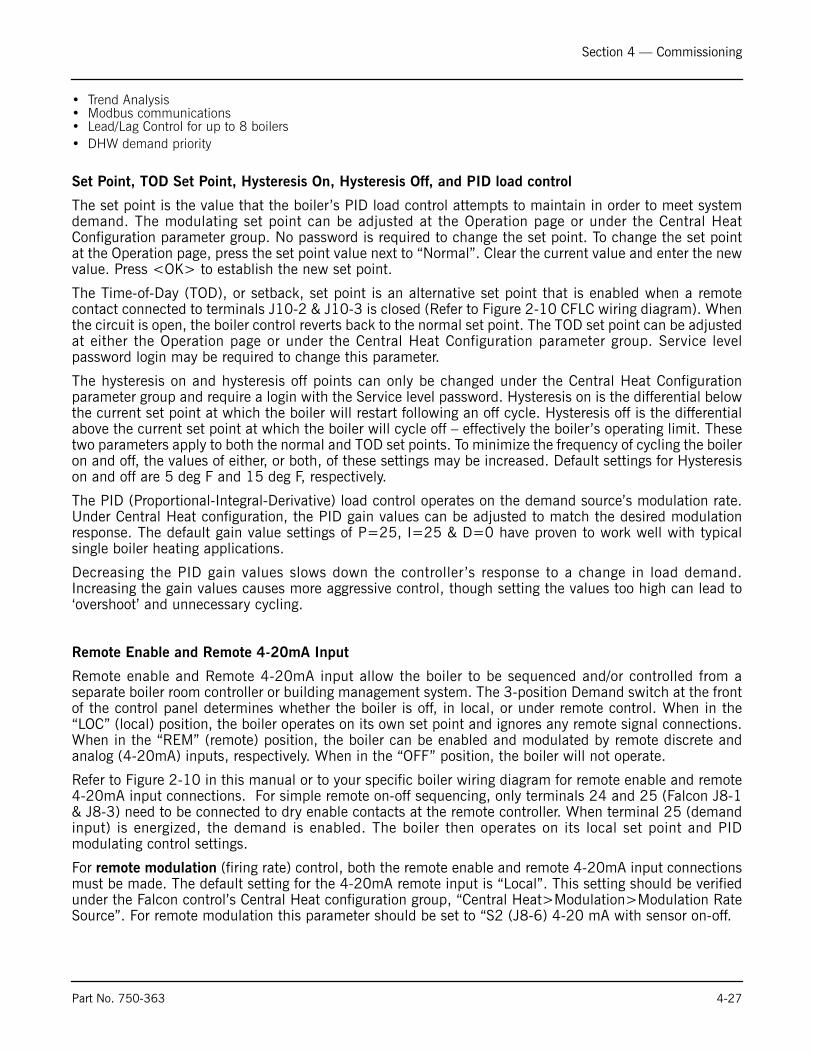
Section 4 — Commissioning
• Trend Analysis• Modbus communications• Lead/Lag Control for up to 8 boilers• DHW demand priority
Set Point, TOD Set Point, Hysteresis On, Hysteresis Off, and PID load control
The set point is the value that the boiler’s PID load control attempts to maintain in order to meet systemdemand. The modulating set point can be adjusted at the Operation page or under the Central HeatConfiguration parameter group. No password is required to change the set point. To change the set pointat the Operation page, press the set point value next to “Normal”. Clear the current value and enter the newvalue. Press <OK> to establish the new set point.
The Time-of-Day (TOD), or setback, set point is an alternative set point that is enabled when a remotecontact connected to terminals J10-2 & J10-3 is closed (Refer to Figure 2-10 CFLC wiring diagram). Whenthe circuit is open, the boiler control reverts back to the normal set point. The TOD set point can be adjustedat either the Operation page or under the Central Heat Configuration parameter group. Service levelpassword login may be required to change this parameter.
The hysteresis on and hysteresis off points can only be changed under the Central Heat Configurationparameter group and require a login with the Service level password. Hysteresis on is the differential belowthe current set point at which the boiler will restart following an off cycle. Hysteresis off is the differentialabove the current set point at which the boiler will cycle off – effectively the boiler’s operating limit. Thesetwo parameters apply to both the normal and TOD set points. To minimize the frequency of cycling the boileron and off, the values of either, or both, of these settings may be increased. Default settings for Hysteresison and off are 5 deg F and 15 deg F, respectively.
The PID (Proportional-Integral-Derivative) load control operates on the demand source’s modulation rate.Under Central Heat configuration, the PID gain values can be adjusted to match the desired modulationresponse. The default gain value settings of P=25, I=25 & D=0 have proven to work well with typicalsingle boiler heating applications.
Decreasing the PID gain values slows down the controller ’s response to a change in load demand.Increasing the gain values causes more aggressive control, though setting the values too high can lead to‘overshoot’ and unnecessary cycling.
Remote Enable and Remote 4-20mA Input
Remote enable and Remote 4-20mA input allow the boiler to be sequenced and/or controlled from aseparate boiler room controller or building management system. The 3-position Demand switch at the frontof the control panel determines whether the boiler is off, in local, or under remote control. When in the“LOC” (local) position, the boiler operates on its own set point and ignores any remote signal connections.When in the “REM” (remote) position, the boiler can be enabled and modulated by remote discrete andanalog (4-20mA) inputs, respectively. When in the “OFF” position, the boiler will not operate.
Refer to Figure 2-10 in this manual or to your specific boiler wiring diagram for remote enable and remote4-20mA input connections. For simple remote on-off sequencing, only terminals 24 and 25 (Falcon J8-1& J8-3) need to be connected to dry enable contacts at the remote controller. When terminal 25 (demandinput) is energized, the demand is enabled. The boiler then operates on its local set point and PIDmodulating control settings.
For remote modulation (firing rate) control, both the remote enable and remote 4-20mA input connectionsmust be made. The default setting for the 4-20mA remote input is “Local”. This setting should be verifiedunder the Falcon control’s Central Heat configuration group, “Central Heat>Modulation>Modulation RateSource”. For remote modulation this parameter should be set to “S2 (J8-6) 4-20 mA with sensor on-off.
Part No. 750-363 4-27

Section 4 — Commissioning
To avoid nuisance operating limit shut downs of the boiler, the Falcon’s normal operating set point shouldbe adjusted to a value that is greater than the system header set point.
With demand present and completion of a successful trial for ignition sequence, the boiler will modulateaccording to the 4-20mA input signal provided: 4mA = minimum modulation rate (low fire); 20mA =maximum modulation rate (high fire). The boiler will continue to modulate until the demand is removed,the operating limit is reached, LCI is opened (e.g. low water condition), or a Falcon lockout alarm occurs(e.g. ILK opens on a High Limit trip).
To configure the boiler for remote set point control, navigate to the Falcon control’s Central Heatconfiguration group. Change the setting of “Central Heat Configuration>Set Point>Set Point Source” to “S2(J8-6) 4-20mA”. Next, the span of the 4-20mA needs to be established. The “20mA water temperature”parameter determines the value for 20mA; “4mA water temperature” determines the value for 4mA.
Depending on the quality of the remote input signal, the modulation rate or operating set point may fluctuateslightly because of small changes in the measured current signal or because of induced noise. Under theModulation configuration group, the “4-20mA input Hysteresis” setting may need to be adjusted to avoidundesired fluctuations in the either the modulation rate or operating set point. The default setting is 0.2mAand can be increased to essentially filter out small fluctuations of the input signal. It may take some trialand error to establish the optimum input hysteresis setting for a particular system.
If at any time the remote 4-20mA input signal is disconnected, the Falcon control will indicate “OPEN” or“LOCAL” under the 4-20mA input value at the operation screen. The boiler will then operate on its local setpoint and PID modulation control. Once the 4-20mA signal is reestablished, the boiler will resumeoperation under remote control.
Rate Limiting/Override
For safety reasons or to accommodate special operating conditions, the Falcon incorporates a number ofcontrol functions that either limit the modulation range or set the firing rate to a specific value. Thesefunctions include Delta T limiting, Slow Start, and Forced Rate. See Appendix A for a complete listing ofcontrol functions with detailed descriptions and parametrization instructions.
Delta T limiting is designed to reduce the firing rate in case of an excessive difference between the inlet andoutlet temperatures caused by a mismatch between water flow rate and boiler firing rate. Sensorconnections to the Falcon are at J8-4 and -5 (inlet temperature) and J8-8,-9, and -10 (outlet temperature).Delta T limiting includes an Inversion Detection mode which when enabled becomes active in case the inlettemperature is higher than the outlet temperature (indicating reverse water flow through the boiler).
Forced Rate limiting causes the burner to stay at a fixed firing rate for a fixed time period immediately afterlightoff, following the Run Stabilization period (if any). The forced rate period is optionally followed by aSlow Start function that limits the ramp-up speed of the firing rate whenever the water is colder than a user-specifiable threshold. Slow Start can help reduce set point overshoot, high limit trips, and frequent cycling.
Configurable Pump/Aux Relay Contacts
The Falcon Pump/Aux Relay outputs are configurable by means of six pre-configured Pump Control Blocks.Each control block is configured for a specific application:
1. Central Heat Pump2. Boiler Pump (for primary/secondary pumping)3. DHW pump4. System Pump5. “Aux 1 Pump” - used for a boiler isolation valve6. “Aux 2 Pump” - used for a boiler Start Permissive Interlock
4-28 Part No. 750-363
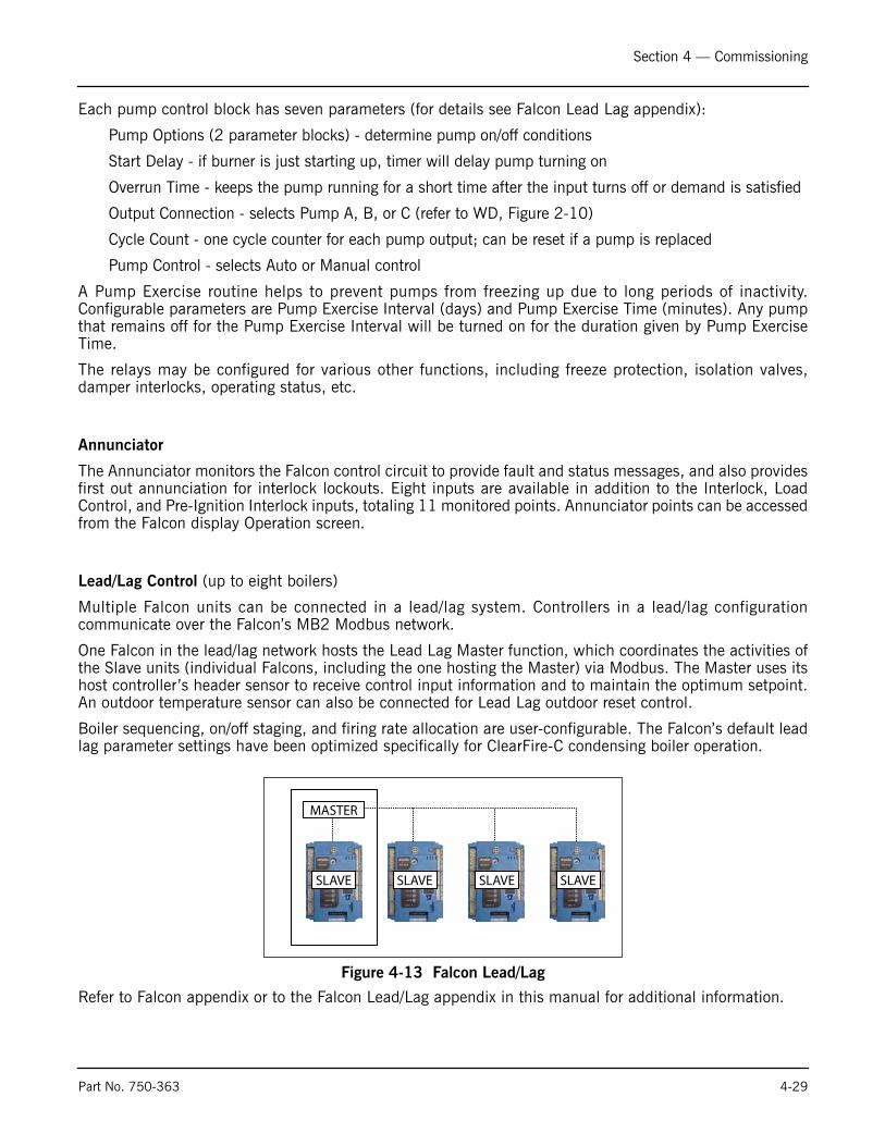
Section 4 — Commissioning
Each pump control block has seven parameters (for details see Falcon Lead Lag appendix):
Pump Options (2 parameter blocks) - determine pump on/off conditions
Start Delay - if burner is just starting up, timer will delay pump turning on
Overrun Time - keeps the pump running for a short time after the input turns off or demand is satisfied
Output Connection - selects Pump A, B, or C (refer to WD, Figure 2-10)
Cycle Count - one cycle counter for each pump output; can be reset if a pump is replaced
Pump Control - selects Auto or Manual control
A Pump Exercise routine helps to prevent pumps from freezing up due to long periods of inactivity.Configurable parameters are Pump Exercise Interval (days) and Pump Exercise Time (minutes). Any pumpthat remains off for the Pump Exercise Interval will be turned on for the duration given by Pump ExerciseTime.
The relays may be configured for various other functions, including freeze protection, isolation valves,damper interlocks, operating status, etc.
Annunciator
The Annunciator monitors the Falcon control circuit to provide fault and status messages, and also providesfirst out annunciation for interlock lockouts. Eight inputs are available in addition to the Interlock, LoadControl, and Pre-Ignition Interlock inputs, totaling 11 monitored points. Annunciator points can be accessedfrom the Falcon display Operation screen.
Lead/Lag Control (up to eight boilers)
Multiple Falcon units can be connected in a lead/lag system. Controllers in a lead/lag configurationcommunicate over the Falcon’s MB2 Modbus network.
One Falcon in the lead/lag network hosts the Lead Lag Master function, which coordinates the activities ofthe Slave units (individual Falcons, including the one hosting the Master) via Modbus. The Master uses itshost controller’s header sensor to receive control input information and to maintain the optimum setpoint.An outdoor temperature sensor can also be connected for Lead Lag outdoor reset control.
Boiler sequencing, on/off staging, and firing rate allocation are user-configurable. The Falcon’s default leadlag parameter settings have been optimized specifically for ClearFire-C condensing boiler operation.
Refer to Falcon appendix or to the Falcon Lead/Lag appendix in this manual for additional information.
Figure 4-13 Falcon Lead/Lag
SLAVE SLAVE SLAVE SLAVE
MASTER
Part No. 750-363 4-29

Section 4 — Commissioning
Modbus Communication
For remote enable / remote setpoint (see above) and for remote monitoring through a building EMS, theFalcon uses the Modbus communication protocol. For more information on Modbus setup andimplementation, see the Falcon Modbus appendix in this manual.
4-30 Part No. 750-363

www.cleaverbrooks.com
Section 5Service and Maintenance
Disassembly for Inspection ...................................................... 5-2Reassembly .......................................................................... 5-3Ignition and Flame Detection Systems ...................................... 5-3Troubleshooting ..................................................................... 5-4Extended Shutdown................................................................ 5-6Emergency Shutdown ............................................................. 5-6
! Caution Label all wires prior to disconnection when
servicing controls. Wiring errors can cause
improper and dangerous operation.Failure to
do so may result in equipment failure.
! CautionVerify proper operation after servicing.
Failure to do so may result in equipment
failure.

Section 5 — Service and Maintenance
On an annual basis the boiler vessel and burner combustion system must be checked and cleaned. Thiswork is to be carried out by an authorized Cleaver-Brooks Service Technician.
A. DISASSEMBLY FOR INSPECTION1. Close off the gas supply to the boiler and disconnect electrical power at the primary switch box.2. Remove the front upper and front left side casing panels.3. Remove the gas train and set aside.4. Disconnect the electrical connections to the blower assembly.5. Disconnect scanner, ignition, and pilot cables.6. Remove air filter (or direct vent coupling if supplied).7. Remove the vent section between the flue collection chamber and the casing roof.8. Remove the nuts securing the blower to the adapter plate.9. The blower will swing out and to the left on its hinge.10. The burner head can be separated by removing the nuts and washers holding the adapter plate to the dry
oven.
Check the burner head for any damage, burn marks or perforations. If damage is found replace the damagedparts. If the canister is in good condition clean out any dirt and contaminates with a vacuum cleaner insideand out, alternating with compressed air to dislodge any debris.
With the burner head and blower removed the combustion chamber can be accessed for all servicerequirements.
Check ignition electrodes for deposits and proper gap. Clean or replace as needed.
Inspect the pressure vessel and combustion chamber area for any damage or contamination. If dirt orcontaminates are found it is recommended that the tubes be washed with a high-pressure power washer.
! Caution
Label all wires prior to disconnection when servicing controls.
Wiring errors can cause improper and dangerous operation.
Verify proper operation after servicing.
5-2 Part No. 750-363

Section 5 — Service and Maintenance
B.REASSEMBLY1. Assembly is the reverse of the above instructions.2. Burner gaskets should be replaced; see recommended spare parts list.3. Replace combustion air filter if dirty. Remove filter retaining rod and install new CB approved filter media;
see recommended spare parts list. Replace rod to hold filter in place.
C. IGNITION AND FLAME DETECTION SYSTEMS
Ignition Electrode
The ignition electrode should be replaced annually, or more frequently if conditions require. Inspect theelectrode periodically for signs of fouling, displacement, or other damage.
Observe the dimensions below when replacing:
1/8” gap between ignitor electrode and ground electrode.
1” from ignitor electrode to the burner canister.
Pilot and UV Scanner
Maintenance of the UV scanner consists of periodic inspection and cleaning. To inspect, unscrew the UV flame detector from the bracket. Check to ensure that the flame viewing lens is clear and free of dust or debris. Wipe with a clean rag if necessary.When replacing the scanner, verify an unobstructed line of sight through the scanner bracket to the burnercanister.
Figure 5-1 Electrode spacing CFLC
1/8” 1”E1/16”
Part No. 750-363 5-3
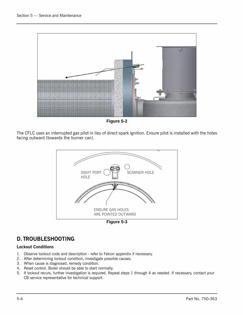
Section 5 — Service and Maintenance
The CFLC uses an interrupted gas pilot in lieu of direct spark ignition. Ensure pilot is installed with the holesfacing outward (towards the burner can).
D.TROUBLESHOOTING
Lockout Conditions
1. Observe lockout code and description - refer to Falcon appendix if necessary.2. After determining lockout condition, investigate possible causes.3. When cause is diagnosed, remedy condition.4. Reset control. Boiler should be able to start normally.5. If lockout recurs, further investigation is required. Repeat steps 1 through 4 as needed. If necessary, contact your
CB service representative for technical support.
Figure 5-2
Figure 5-3
ENSURE GAS HOLESARE POINTED OUTWARD
SCANNER HOLESIGHT PORTHOLE
5-4 Part No. 750-363

Section 5 — Service and Maintenance
EXAMPLE: Lockout 79 Outlet Temperature High Limit
1. Before resetting control to clear lockout, check for sufficient water flow through boiler. Possible sources of insuffi-cient flow include closed water valves, insufficient pump speed, air trapped in boiler (inadequate air venting), or modulation set point and off point close to outlet high limit setting.
The Falcon system display/interface provides extensive boiler diagnostic data at the time of lockout that can help in determining the source of a problem. This information is accessed through the Lockout History.
2. Remedy condition that caused lockout to occur.3. Reset control by pressing <Clear Lockout> from the Lockout History screen.
Light-off Problems
Check electrode positioning according to Section C above.
The dimensions on the ignition electrodes are not easily adjustable - bending the rods can cause damageto the insulation material. In addition, a bent electrode will return to its original shape when heated. If anignitor or flame rod is out of specification, replacement is generally required. Clean or replace as necessary.
Also see Troubleshooting Chart below.
Troubleshooting Chart
Symptom/Fault Indication Possible Causes
Erratic display/controller behavior Faulty electrical ground - Check ground terminals in control panel. System should be grounded firmly to metal casing. External ground wiring may be necessary.
Touch screen not working properly Screen out of calibration - from Falcon home page, go to Setup/Advanced Setup/Diagnostics. Under “Touch Screen” press <Calibrate> and follow instructions on screen.
Burner can failure;High Gas Pressure lockouts
Incorrect gas pressure:
• Check regulated gas pressure and ensure it agrees with Table 4-3. Check other equipment connected to gas main - regulator and gas supply piping sizings should be based on all appliances being ON.
• A dedicated, properly sized gas pressure regulator is required for each boiler.
• Customer connection should reduce to boiler gas train.
Lightoff problems • Wrong gas pressure. Check regulated gas pressure and ensure it agrees with Table 4-3. Check other equipment connected to gas main - regulator and gas supply piping sizings should be based on all appliances being ON.
• Incorrect fan speed settings - increase fan speed by 100 RPM increments until successful lightoff occurs.
• Bad cable connections (ignition or flame rod)
• Electrodes fouled or improperly spaced - electrodes should be cleaned or replaced and spacing adjusted.
• Debris on burner canister. To clean the unit, remove the burner can and blow compressed air from the outside in. Vacuum up the residue.
• Electrical ground problem
Part No. 750-363 5-5

Section 5 — Service and Maintenance
E. EXTENDED SHUTDOWNWhen shutting down the boiler for an extended period of time, use the following general guidelines:
1. Turn the demand switch to the OFF position.2. Close all main fuel valves.3. If the boiler operates in a damp environment, cover electrical components in plastic to protect from moisture.
To restart after an extended period, follow the initial startup instructions in Chapter 4.
F. EMERGENCY SHUTDOWNIn case of emergency, shut down the boiler by turning the demand switch to the OFF position. Shut off themain manual fuel shutoff valves on the fuel supply line. The unit can also be shut down with the mainelectrical power disconnect. Inspect and troubleshoot the boiler before attempting to restart. Followinstructions in Chapter 4 for restart and continued operation.
Outlet Temperature High Limit lockout • Insufficient water flow through boiler - closed water valves, insufficient pump speed
• Air trapped in boiler
• Modulation set point and off point too close to outlet high limit setting
Interrupted Air Switch lockout • Blower not running
• Blocked blower inlet
• CAPS switch defective or improperly wired
Loss of flame • Debris on burner
• Blocked condensate drain
• Combustion improperly set
• Flame scanner soiled, obstructed, or out of position
Symptom/Fault Indication Possible Causes
5-6 Part No. 750-363

Section 6Parts
Recommended Spare Parts List . . . . . . . . . . . . . . . . . . . . . . . . . . . . . . . . . . . . . . . . . . . . . . . . . . . . . . . . . 6-1Boiler Mechanical Assembly CFLC 4000-5000 . . . . . . . . . . . . . . . . . . . . . . . . . . . . . . . . . . . . . . . . . . . . . . 6-2Burner Assembly CFLC 4000/5000 . . . . . . . . . . . . . . . . . . . . . . . . . . . . . . . . . . . . . . . . . . . . . . . . . . . . . . 6-3Gas Train CFLC 4000/5000 . . . . . . . . . . . . . . . . . . . . . . . . . . . . . . . . . . . . . . . . . . . . . . . . . . . . . . . . . . . 6-4Gas Train (9 ppm) CFLC 4000/5000 . . . . . . . . . . . . . . . . . . . . . . . . . . . . . . . . . . . . . . . . . . . . . . . . . . . . . 6-5Control Panel . . . . . . . . . . . . . . . . . . . . . . . . . . . . . . . . . . . . . . . . . . . . . . . . . . . . . . . . . . . . . . . . . . . . . . 6-6Cables and Cable Harness . . . . . . . . . . . . . . . . . . . . . . . . . . . . . . . . . . . . . . . . . . . . . . . . . . . . . . . . . . . . . 6-7
Recommended Spare Parts List Model CFLC
Boiler Size
Item Qty 4000 / 5000
Falcon Controller, Hydronic 1 833-04097Display/Operator Interface, Falcon System 1 833-05105UV Scanner 1 817-01743Dual Electrode, Sparking 1 380-01061Electrode Gasket 3 380-01032Burner Canister 1 380-01130Water Side Gaskets 5 853-00934Transformer, 115V/25V 1 832-00235Relay, DPDT, 115VAC Coil 1 833-03532Gasket, Burner Canister 2 380-01118Gasket, Adapter to Blower 1 380-01121Cable, Gas Pilot 1 826-00262Ignition Cable (2) 1 826-00298Burner Sight Glass 1 851-00026Retainer, Sight Glass 1 952-00498Gasket, Sight Glass 2 853-00213Filter Media 332-00091
Blower Fuse (9A) 3 832-01885Fuse (5A), Control Circuit 2 832-01811Fuse (4A), Control Circuit 1 832-01810Fuse (2A), 24VAC Secondary 1 832-02051
www.cleaverbrooks.com

Section 6 — Parts
Figure 6-1. Boiler Mechanical Assembly CFLC 4000-5000
DRY OVEN DETAIL
ITEM QTY CFLC 4000 CFLC 5000 DESCRIPTION1 1 270-03748-000 PRESSURE VESSEL ASSEMBLY2 1 853-00996-000 ROPE, 1/2" DIA. X 80" LG.3 1 429-01882-000 BURNER ASSEMBLY6 1 465-02772-000 INSULATION & LAGGING ASSEMBLY7 1 426-03299-000 DUCT, STACK STARTER SECTION, 14" DIA.8 1 426-03300-000 DUCT, STACK REMOVABLE SECTION, 14" DIA. W/BANDS9 1 426-03301-000 DUCT, STACK SUPPORT, 14" DIA.11 1 872-00622-000 ROPE, 1/2" DIA. x 45" LG.16 1 185-01263-000 GAS TRAIN, MAIN GAS17 1 185-01264-000 PIPING, PILOT GAS TRAIN22 1 833-03362-000 DRIVE, VARIABLE SPEED
30 1 507-09839-000 PIPING, AIR VENT AND LWCO PROBE HOLDER31 1 656-10183-000 INSTALLATION, PRESSURE GAUGE & THERMOMETER32 1 283-03650-000 CONTROL PANEL, CFLC33 1 189-01425-000 PIPING, CONDENSATE DRAIN36 1 817-00405-000 WELL, SEPARABLE, 1/2" NPT. W/CLAMP41 1 826-00296-000 CABLE HARNESS, MALE END42 1 090-04682-000 TUBING, AIR SENSING LINE45 1 940-05199-000 VALVE RELIEF, 160 PSI. 1" x 1-1/4" (STANDARD, SHIP LOOSE)46 1 940-00601-000 VALVE RELIEF, 125 PSI. 1" x 1-1/4" (OPTIONAL, SHIP LOOSE)47 1 940-00566-000 VALVE RELIEF, 60 PSI. 1-1/2" x 2" (OPTIONAL, SHIP LOOSE)48 1 940-00962-000 VALVE RELIEF, 30 PSI. 2" x 2-1/2" (OPTIONAL, SHIP LOOSE)50 1 880-02711-000 KIT, AIR FILTER, CFLC51 1 462-00243-000 HINGE ASSEMBLY, BLOWER
3
4
5
2
FRONT PLATE
FURNACE
1
6
11
161716
18
22
22
30
33
45464748
DRY OVEN
7
8
9
42
51
31
31
31
32
270-03739-000853-00996-000429-01809-000465-02772-000426-03299-000426-03300-000426-03301-000872-00622-000185-01263-000185-01264-000833-03362-000
507-09839-000656-10183-000283-03650-000189-01425-000817-00405-000826-00296-000090-04682-000940-05199-000940-00601-000940-00566-000940-00962-000880-02711-000462-00243-000
6-2 Part No. 750-363

Section 6 — Parts
Figure 6-2. Burner Assembly CFLC 4000/5000
SECTION C-C
DESCRIPTIONCFLC 4000 CFLC 5000QTYITEMDRY OVEN ASSEMBLY279-00749-00011GASKET, BURNER CANISTER380-01118-00022ADAPTER PLATE, BURNER TO BLOWER380-01119-00013SIGHT GLASS GASKET853-00213-00024SIGHT GLASS851-00026-00015ELECTRODE, DUAL, CLEARFIRE IGNITION380-01061-00018GASKET, ELECTRODE380-01032-000212TUBE, GAS PILOT090-04464-000113BURNER CAN380-01130-000116BLOWER, COMBUSTION AIR894-05502-000117VENTURI ASSEMBLY048-00859-000118GASKET, BLOWER INLET & OUTLET380-01121-000219COMBUSTION AIR PROVING SWITCH817-03468-000122PRESSURE SWITCH, 3-21"WC RANGE, MR, 1/4" NPT MOUNT817-02420-000128
A
SCANNERHOLE
SIGHT PORTHOLE
ENSURE GAS HOLES AREPOINTED OUTWARD
161
2
16
2
19
17
19
18
14
3
12
13
4 5
128
16
18
27
CAPSHAPS
1 116"
1316
8
DETAIL A22
2830
TO FRONT OFGAS ACTUATOR
894-05372-000
279-00749-000380-01118-000380-01119-000853-00213-000851-00026-000380-01061-000380-01032-000090-04464-000380-01130-000
048-00859-000380-01121-000817-03468-000817-02420-000
SCANNER ASSEMBLY - UV817-01743-000129CONNECTOR, STRAIGHT, 3/8"848-00003-000130BUSHING, ANTI-SHORT, GREENFIELD, 3/8"848-00100-000231CONDUIT, FLEX, GREENFIELD, 3/8" x 60" LG.827-00006-000132
32313029
Part No. 750-363 6-3

Section 6 — Parts
6-4
Figure 6-3 Gas train CFLC 4000/5000
DESCRIPTIONPART NOQTYITEMBALL VALVE, 1-1/2" NPT.941-01946-00015VALVE BODY, 1-1/2" NPT, MOTORIZED, GAS949-00461-00017ACTUATOR, SIEMENS SKP75.011U1797-07871-00018REGULATOR, GAS PRESSURE, MAXITROL #210E, 2"NPT, 15"-30" WC918-00161-000116VALVE, BUTTERBALL, 2" NPT.941-01947-000119LEAKAGE TEST COCK, 1/8" NPT.825-00239-000221LGPS, 3-21"WC RANGE, MR, 1/4" NPT MOUNT817-02416-000124PRESSURE SWITCH, 3-21"WC RANGE, MR, 1/4" NPT MOUNT817-02420-000127CONNECTOR, COMP, BRASS, 1/4" NPT. x 3/8" ODC845-00022-000228TUBING, ALUMINUM, 3/8" O.D. x .035" WALL x 21" LG.939-00413-000129ORIFICE, 20PPM NATURAL GAS048-00871-000131
TO VENTURI
5
7
1619
7
21
21
24
27
25
26
25
28
16
TO PILOT LINE
29
28
2928
8
8
8
7
30
30
31
Part No. 750-363

Section 6 — Parts
Figure 6-4. Gas Train (9 ppm) CFLC 4000/5000
ITEM QTY PART NO DESCRIPTION5 1 941-01946-000 BALL VALVE, 1-1/2" NPT.7 1 949-00461-000 VALVE BODY, 1-1/2" NPT, MOTORIZED, GAS8 1 797-07871-000 ACTUATOR16 1 918-00161-000 REGULATOR, GAS PRESSURE (OPTIONAL)19 1 941-01947-000 VALVE, BUTTERBALL, 2" NPT.21 2 825-00239-000 LEAKAGE TEST COCK, 1/8" NPT.22 2 858-00088-000 PIPE PLUG, SQ. HD. 1/8" NPT 150# M.I., B16.1424 1 817-02416-000 LGPS, 3-21"WC RANGE, MR, 1/4" NPT MOUNT27 1 817-02420-000 PRESSURE SWITCH, 3-21"WC RANGE, MR, 1/4" NPT MOUNT28 2 845-00022-000 CONNECTOR, COMP, BRASS, 1/4" NPT. x 3/8" ODC29 1 939-00413-000 TUBING, ALUMINUM, 3/8" O.D. x .035" WALL x 14" LG.31 1 048-00872-000 ORIFICE, 9PPM NATURAL GAS32 1 048-00873-000 ORIFICE ASSEMBLY, NATURAL GAS SENSING LINE, 9 PPM35 1 235-00091-000 VALVE, SOLENOID, GAS PILOT, 1/4" NPT.36 1 845-00468-000 CONNECTOR, .125" MPT. x .25" ODC37 1 939-00642-000 BULK TUBING, ALUMINUM, 1/4" ODC x .035" WALL x 14" LG.
TO VENTURI
5
7
1619
7
21
22
20
21 22
24
27
28
16
TO PILOT LINE
29
28
88
8
7
30
30
31
32
35
3337
36
3233
Part No. 750-363 6-5
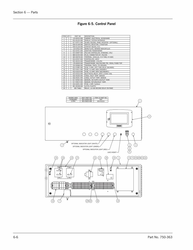
Section 6 — Parts
6
Figure 6-5. Control Panel
DESCRIPTIONPART NOQTYITEMCABINET, ELECTRICAL, W/SUB-BASE119-00433-00011DISPLAY, SYSTEM INTERFACE833-05105-00012ALARM, BUZZER, PANEL MOUNTED (OPTIONAL)817-03571-00013SWITCH, SELECTOR, 3 POSITION836-01148-00014CONTACT BLOCK, N.O.836-01136-00055NAME PLATE, DEMAND REM/OFF/LOC118-03922-00016IGNITION TRANSFORMER832-02451-00017FALCON CONTROLLER, HYDRONIC, CFLC833-04097-00018PLUG, CONNECTOR KIT, FALCON880-02343-00019TERMINAL, SCRULUG, #14 THRU #4 AWG884-00078-000210CONTROLLER, LWCO833-03547-000111TRANSFORMER, 115v/25v832-00235-000112TRANSFORMER, 460/230/208V PRI, 350VA, FUSED TOP178-00049-000113TERMINAL TRACK, CFx BOILERS434-00088-000114FUSE, 9 AMP, LPCC TIME DELAY (BLOWER)832-01885-000315FUSE, 5.0 AMP, 600V (PRIMARY)832-01811-000216FUSE, 4.0 AMP, 600V (SECONDARY)832-01810-000117ELECTRICAL-RELAY, DPDT,115VAC COIL833-03532-000118CABLE, INLET TEMP. SENSOR826-00200-000119CABLE, OUTLET TEMP. SENSOR826-00201-000120SENSOR, HW SUPPLY/OUTLET TEMP.817-04403-000121SENSOR, RETURN/INLET TEMP.817-04814-000122FUSE, 2 AMP, 5x20mm832-02051-000123LATCH, PLASTIC881-00348-000124RELAY, 1.8-180 SECOND DELAY ON MAKESEE TABLE125
34
5
6
2
LWCO RESET
OPTIONAL INDICATOR LIGHT (RED)
OPTIONAL INDICATOR LIGHT (GREEN)
OPTIONAL INDICATOR LIGHT (WHITE)7
1
1 8 9 19 20 21 2211121310 10
14715
16 17
182324
WHERE USED ASSY PART NO. ITEM 25 PART NO.STANDARD 283-03650-000 N/A
9 PPM 283-03653-000 833-01223
25
-6 Part No. 750-363

Section 6 — Parts
Figure 6-6. Cables and Cable Harness
BLOWER
CONTROL PANEL
LOW WATER PROBE
INSIDE ENCLOSURE
OUTSIDE ENCLOSURE
GAS VALVE
HIGH GAS PRESSURE SWITCH
LOW GAS PRESSURE SWITCH
IGNITION
UV SCANNER
HIGH AIR PRESSURE SWITCH
COMBUSTION AIR PRESSURE SWITCH
LWCO
TERMINAL STRIPFALCON
GROMMET
WATER TEMP.SENSORSWIRES
IGNITIONTRANSFORMER
CABLE HARNESS LAYOUT
PILOT SOLENOID VALVE
30
31
FUSE BLOCK
32
33
37
XFMR
VSD
INCOMINGPOWER
DESCRIPTIONPART NOQTYITEMCABLE, IGNITION826-00298-000230CABLE HARNESS, FEMALE END826-00297-000131CABLE, UV SCANNER TO FALCON J1826-00211-000132SCANNER ASSEMBLY - UV817-01743-000133CONNECTOR, STRAIGHT, 3/8"848-00003-000134BUSHING, ANTI-SHORT, GREENFIELD, 3/8"848-00100-000235CONDUIT, FLEX, GREENFIELD, 3/8" x 60" LG.827-00006-000136CABLE, GAS PILOT SOLENOID826-00262-000137CABLE HARNESS, MALE END826-00296-000138
38
34
35
36
Part No. 750-363 6-7

Section 6 — Parts
6-8 Part No. 750-363