premium monitoring system - waterloo...
TRANSCRIPT

Premium Monitoring System
Operation and Maintenance Manual
750-352

Premium Monitoring System 750-352
2

750-352 Premium Monitoring System
S1.
2.
3.
4.
5.
6.
TABLE OF CONTENTS
Specifications . . . . . . . . . . . . . . . . . . . . . . . . . . . . . . . . . 3
Introduction . . . . . . . . . . . . . . . . . . . . . . . . . . . . . . . . . . 4
Wiring . . . . . . . . . . . . . . . . . . . . . . . . . . . . . . . . . . . . . . 4
Installation . . . . . . . . . . . . . . . . . . . . . . . . . . . . . . . . . . . 5
Configuration . . . . . . . . . . . . . . . . . . . . . . . . . . . . . . . . . 7
Parts . . . . . . . . . . . . . . . . . . . . . . . . . . . . . . . . . . . . . . . 15
PECIFICATIONS POWER : 24 VDC ± 10% 200 mA min., without expansion card1 Amp maximum with expansion card fittedMust use Class 2 or SELV rated power supply.
COMMUNICATIONS :USB/PG Port : Adheres to USB specification 1.1. Device only using Type B
connection.
Serial Ports : Format and Baud Rates for each port are individually softwareprogrammable up to 115,200 baud.
RS232/PG Port : RS232 port via RJ12COMMS Ports : RS422/485 port via RJ45, and RS232 port via RJ12DH485 TXEN : Transmit enable; open collector, VOH = 15 VDC,
V OL = 0.5 V @ 25 mA max.Ethernet Port : 10 BASE-T / 100 BASE-TX
RJ45 jack is wired as a NIC (Network Interface Card). LEDs :STS – Status LED indicates condition of Data Station.TX/RX – Transmit/Receive LEDs show serial activity.Ethernet – Link and activity LEDs.CF – CompactFlash LED indicates card status and read/write activity
MEMORY :On-board User Memory: 4 Mbytes of non-volatile Flash memory.On-board SDRAM:
833-03717: 2 Mbytes833-03718: 8 Mbytes
Memory Card: CompactFlash Type II slot for Type I and Type II cards. REAL-TIME CLOCK : Typical accuracy is less than one minute per monthdrift. CB Configurator’s SNTP facility allows synchronization with externalservers.Battery: Lithium Coin Cell. Typical lifetime of 10 years at 25 ºC.
A “Battery Low” system variable is available so that the programmer canchoose specific action(s) to occur when the battery voltage drops belowits nominal voltage.
ENVIRONMENTAL CONDITIONS :Operating Temperature Range: 0 to 50°CStorage Temperature Range: -30 to +70°COperating and Storage Humidity: 80% max relative humidity,
non-condensing, from 0 to 50°CVibration According to IEC 68-2-6: Operational 5 to 150 Hz, in X, Y, Z
direction for 1.5 hours, 2 g’s.Shock According to IEC 68-2-27: Operational 30 g, 11 msec in 3 directions.Altitude: Up to 2000 meters
7. CONSTRUCTION : Case body is burgundy high impact plastic andstainless steel. Installation Category I, Pollution Degree 2.
8. POWER CONNECTION : Removable wire clamp screw terminal block.Wire Gage Capacity: 24 AWG to 12 AWGTorque: 4.45 to 5.34 in/lb (0.5 to 0.6 N-m)
9. MOUNTING : Snaps onto standard DIN style top hat (T) profile mountingrails according to EN50022 -35 x 7.5 and -35 x 15.
10. CERTIFICATIONS AND COMPLIANCES : SAFETYUL Listed, File #E302106, UL508, CSA 22.2 No. 14-M05
LISTED by Und. Lab. Inc. to U.S. and Canadian safety standardsUL Listed, File #E317425, ANSI/ISA 12.12.01-2007, CSA 22.2 No. 213-M1987
LISTED by Und. Lab. Inc. to U.S. and Canadian safety standardsIEC 61010-1, EN 61010-1: Safety requirements for electrical equipment for
measurement, control, and laboratory use, Part 1.ELECTROMAGNETIC COMPATIBILITY
Emissions and Immunity to EN 61326: Electrical Equipment forMeasurement, Control and Laboratory use.
Notes:1. Criterion A: Normal operation within specified limits.2. This device was designed for installation in an enclosure. To avoid
electrostatic discharge to the unit in environments with static levels above4 kV precautions should be taken when the device is mounted outside anenclosure. When working in an enclosure (ex. making adjustments, settingjumpers etc.) typical anti-static precautions should be observed beforetouching the unit.
11. WEIGHT : 15.1 oz (456.4 g)
Immunity to Industrial Locations :
Electrostatic discharge EN 61000-4-2 Criterion A 2
4 kV contact discharge
8 kV air discharge
Electromagnetic RF fields EN 61000-4-3 Criterion A
10 V/m
Fast transients (burst) EN 61000-4-4 Criterion A
2 kV power
2 kV signal
Surge EN 61000-4-5 Criterion A
1kV L-L,2 kV L&N-E power
RF conducted interference EN 61000-4-6 Criterion A
3 V/rms
Emissions:Emissions EN 55011 Class A
WARNING - DO NOT CONNECT OR DISCONNECT CABLESWHILE POWER IS APPLIED UNLESS AREA IS KNOWN TO BENON-HAZARDOUS. USB PORT IS FOR SYSTEM SET-UP ANDDIAGNOSTICS AND IS NOT INTENDED FOR PERMANENTCONNECTION.
WARNING - EXPLOSION HAZARD - DO NOT DISCONNECTEQUIPMENT UNLESS POWER HAS BEEN SWITCHED OFF ORAREA IS KNOWN TO BE NON-HAZARDOUS.
3
Premium Monitoring System 750-352
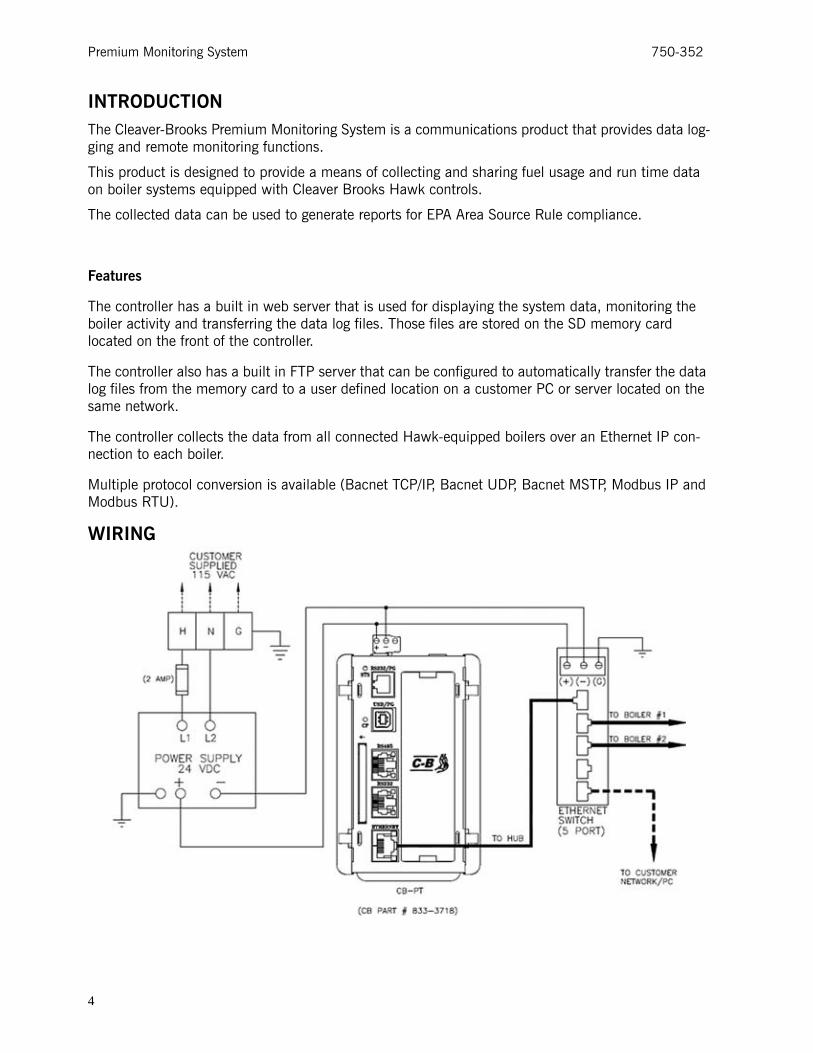
INTRODUCTIONThe Cleaver-Brooks Premium Monitoring System is a communications product that provides data log-ging and remote monitoring functions.
This product is designed to provide a means of collecting and sharing fuel usage and run time data on boiler systems equipped with Cleaver Brooks Hawk controls.
The collected data can be used to generate reports for EPA Area Source Rule compliance.
Features
The controller has a built in web server that is used for displaying the system data, monitoring the boiler activity and transferring the data log files. Those files are stored on the SD memory card located on the front of the controller.
The controller also has a built in FTP server that can be configured to automatically transfer the data log files from the memory card to a user defined location on a customer PC or server located on the same network.
The controller collects the data from all connected Hawk-equipped boilers over an Ethernet IP con-nection to each boiler.
Multiple protocol conversion is available (Bacnet TCP/IP, Bacnet UDP, Bacnet MSTP, Modbus IP and Modbus RTU).
WIRING
4

750-352 Premium Monitoring System
INSTALLATION Transmitters
Note that the transmitters required to capture the data are to be connected to the Hawk boiler con-trols. Refer to the O&M manuals for those products as to how to connect and configure those con-trols.
The data tags that transfer the transmitter values, totalized values and other boiler information exist in the Hawk software and are automatically picked up and displayed / logged to the web server.
Displayed Data
Typical values displayed on the boiler overview screen:
Analog Values Eng Units Min-Max
Flame Strength Honeywell Volts 0-5
Combustion Air Fan Speed RPM 0-3600
Blower Motor Kw Kilowatts 0-100
Boiler Efficiency % 0-100
Firing Rate % 0-100
O2 Level % 0-25
Set Point Steam Pressure/Water Temp PSI or Deg F 0-1000
Water Level Inches WC 0-6
Steam Pressure or HW Temp PSI or Deg F 0-1000
Stack Temperature Before Econ. Deg F 0-1000
Combustion Air Temperature Deg F 0-1000
Water Temperature Shell/Outdoor Temp Deg F 0-1000
Feedwater Temperature/Econ Water Out Temp Deg F 0-1000
Stack Temp. After Econ./Return HW Deg F 0-1000
Economizer Water In Temp Deg F 0-1000
5

Premium Monitoring System 750-352
Data Logs
Typical values written to the data logs shown below. There are 3 log files per boiler.
All data log files are in CSV format and are time and date stamped.
BxUsrIn where x = the boiler number. It contains the values for the Analog User Inputs.
Analog Values Eng Units Min-Max
AR16-Analog Input User Defined #0 Input User Def User Def
AR17-Analog Input User Defined #1 Input User Def User Def
AR18-Analog Input User Defined #2 Input User Def User Def
AR19-Analog Input User Defined #3 Input User Def User Def
BxSystem where x = the boiler number. It contains the operating values.
Analog Values Eng Units Min-Max
AR0-Flame Strength Honeywell Volts 0-5
AR4-Firing Rate % 0-100
AR5-O2 Level % 0-25
AR8-Steam Pressure or HW Temp PSI or Deg F 0-1000
AR10-Stack Temperature Before Econ. Deg F 0-1000
Totalized values for the User Analog Inputs, defined for flow are available as well.
Total Run Time for each fuel is also included You can also see these values on the RUN DATA display.
BxFlwTot where x = the boiler number.
Analog Values Eng Units
Fuel1min Minutes
Fuel1hr Hours
Fuel2min Minutes
Fuel2hr Hours
N202_12 Elapsed Time Hours
F250_204 Analog Input User Defined #0 Input Totalized User Defined
F250_205 Analog Input User Defined #1 Input Totalized User Defined
F250_206 Analog Input User Defined #2 Input Totalized User Defined
F250_207 Analog Input User Defined #3 Input Totalized User Defined
6
750-352 Premium Monitoring System
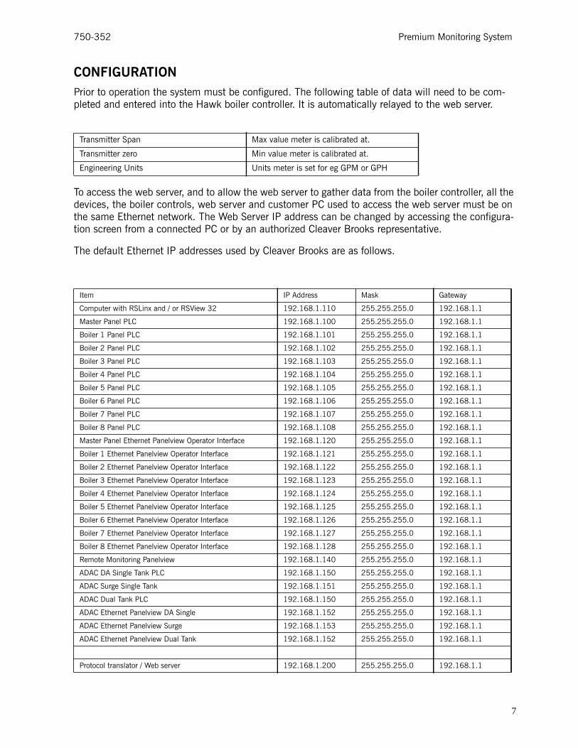
CONFIGURATIONPrior to operation the system must be configured. The following table of data will need to be com-pleted and entered into the Hawk boiler controller. It is automatically relayed to the web server.
To access the web server, and to allow the web server to gather data from the boiler controller, all the devices, the boiler controls, web server and customer PC used to access the web server must be on the same Ethernet network. The Web Server IP address can be changed by accessing the configura-tion screen from a connected PC or by an authorized Cleaver Brooks representative.
The default Ethernet IP addresses used by Cleaver Brooks are as follows.
Transmitter Span Max value meter is calibrated at.
Transmitter zero Min value meter is calibrated at.
Engineering Units Units meter is set for eg GPM or GPH
Item IP Address Mask Gateway
Computer with RSLinx and / or RSView 32 192.168.1.110 255.255.255.0 192.168.1.1
Master Panel PLC 192.168.1.100 255.255.255.0 192.168.1.1
Boiler 1 Panel PLC 192.168.1.101 255.255.255.0 192.168.1.1
Boiler 2 Panel PLC 192.168.1.102 255.255.255.0 192.168.1.1
Boiler 3 Panel PLC 192.168.1.103 255.255.255.0 192.168.1.1
Boiler 4 Panel PLC 192.168.1.104 255.255.255.0 192.168.1.1
Boiler 5 Panel PLC 192.168.1.105 255.255.255.0 192.168.1.1
Boiler 6 Panel PLC 192.168.1.106 255.255.255.0 192.168.1.1
Boiler 7 Panel PLC 192.168.1.107 255.255.255.0 192.168.1.1
Boiler 8 Panel PLC 192.168.1.108 255.255.255.0 192.168.1.1
Master Panel Ethernet Panelview Operator Interface 192.168.1.120 255.255.255.0 192.168.1.1
Boiler 1 Ethernet Panelview Operator Interface 192.168.1.121 255.255.255.0 192.168.1.1
Boiler 2 Ethernet Panelview Operator Interface 192.168.1.122 255.255.255.0 192.168.1.1
Boiler 3 Ethernet Panelview Operator Interface 192.168.1.123 255.255.255.0 192.168.1.1
Boiler 4 Ethernet Panelview Operator Interface 192.168.1.124 255.255.255.0 192.168.1.1
Boiler 5 Ethernet Panelview Operator Interface 192.168.1.125 255.255.255.0 192.168.1.1
Boiler 6 Ethernet Panelview Operator Interface 192.168.1.126 255.255.255.0 192.168.1.1
Boiler 7 Ethernet Panelview Operator Interface 192.168.1.127 255.255.255.0 192.168.1.1
Boiler 8 Ethernet Panelview Operator Interface 192.168.1.128 255.255.255.0 192.168.1.1
Remote Monitoring Panelview 192.168.1.140 255.255.255.0 192.168.1.1
ADAC DA Single Tank PLC 192.168.1.150 255.255.255.0 192.168.1.1
ADAC Surge Single Tank 192.168.1.151 255.255.255.0 192.168.1.1
ADAC Dual Tank PLC 192.168.1.150 255.255.255.0 192.168.1.1
ADAC Ethernet Panelview DA Single 192.168.1.152 255.255.255.0 192.168.1.1
ADAC Ethernet Panelview Surge 192.168.1.153 255.255.255.0 192.168.1.1
ADAC Ethernet Panelview Dual Tank 192.168.1.152 255.255.255.0 192.168.1.1
Protocol translator / Web server 192.168.1.200 255.255.255.0 192.168.1.1
7

Premium Monitoring System 750-352
To change the IP address, use the pop up key pad to input ALL the data required then click on the "Set IP Address" button. Note you will lose communications with the web server until you have your PC set up on the same IP Address range again. Note ALL devices on a network MUST have unique IP addresses.
For email, you need to get your email server information from your IT department.
A pop up keypad will allow you to input the information into the different cells. When complete, you can use the "Test E-Mail" button to send a test email to the accounts you have set up.
Data Log Screen
When you first access the web server, you will see this screen. To return to this screen at any time, click on the BACK button in your web browser.
Sample Screens
Display Screen Menu
This screen allows you to navigate to the various displays.
8
750-352 Premium Monitoring System
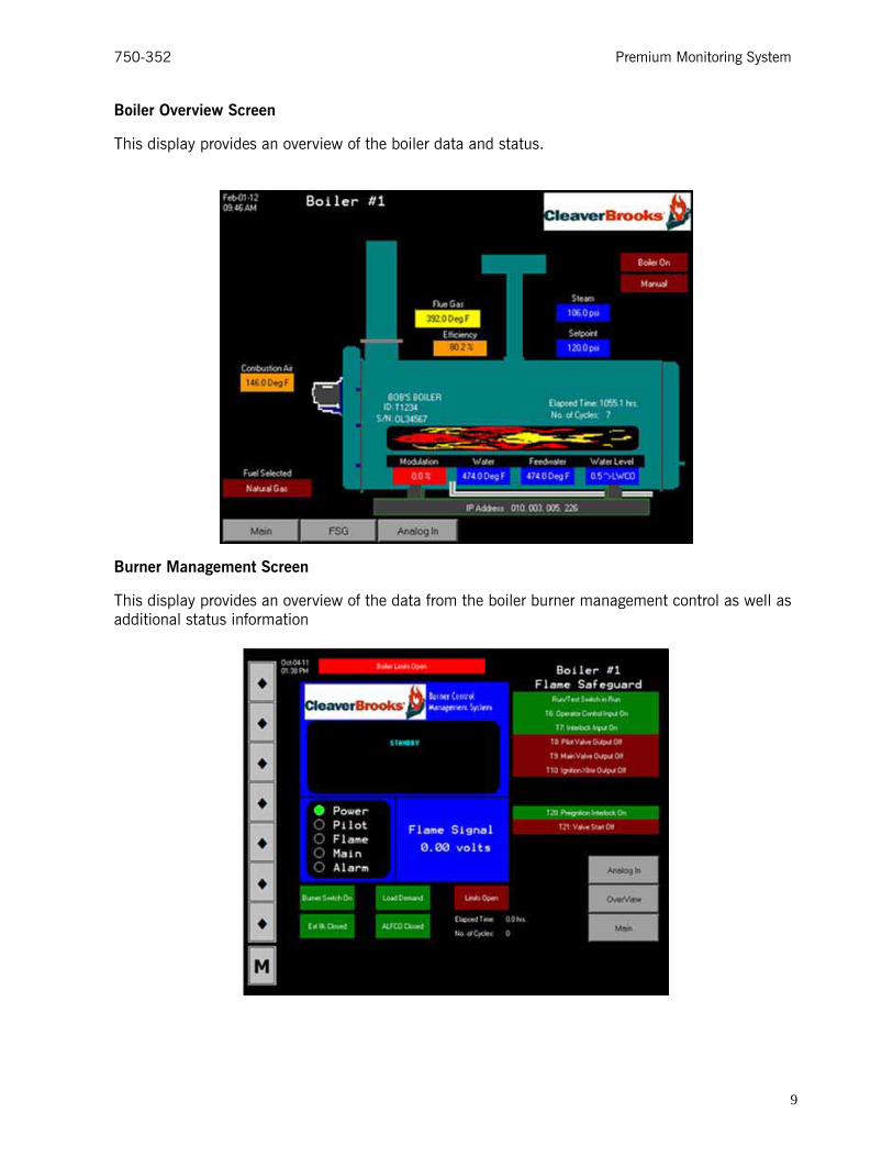
Boiler Overview Screen
This display provides an overview of the boiler data and status.
Burner Management Screen
This display provides an overview of the data from the boiler burner management control as well as additional status information
9

Premium Monitoring System 750-352
Analog Input Screen
This display provides instantaneous and totalized values of any configured user analog inputs if avail-able on your Hawk boiler control.
Alarm History Screen
This display provides a history of all the alarms with time and date stamps and an English text description of the alarm itself. The <Clear> button permanently erases the alarm history. The <Next> and <Previous> buttons allow you to move forward and backward through the alarm history one page at a time.
10

750-352 Premium Monitoring System
IP Address and Email Set up Display
This display is password protected and is used in the initial set up of the system to define the IP address, Subnet Mask, and Gateway, as well as setting up the email addresses that you wish to send the alarm messages to (optional).
To set the date and time, click on the item you wish to change. A pop up will appear allowing you to select the item to change; the up and down arrows increment or decrement the value
The user ID and password are available from your local Cleaver Brooks representative.
To change the IP address, use the pop up key pad to input ALL the data required then click on the "Set IP Address" button. Note: you will lose communications with the web server until you have your PC set up on the same IP Address range again. ALL devices on a network MUST have unique IP addresses.
For email, you need to get your email server information from your IT department.
A pop up keypad will allow you to input the information into the different cells. When finished, you can use the "Test E-Mail" button to send a test email to the accounts you have set up.
11
Premium Monitoring System 750-352
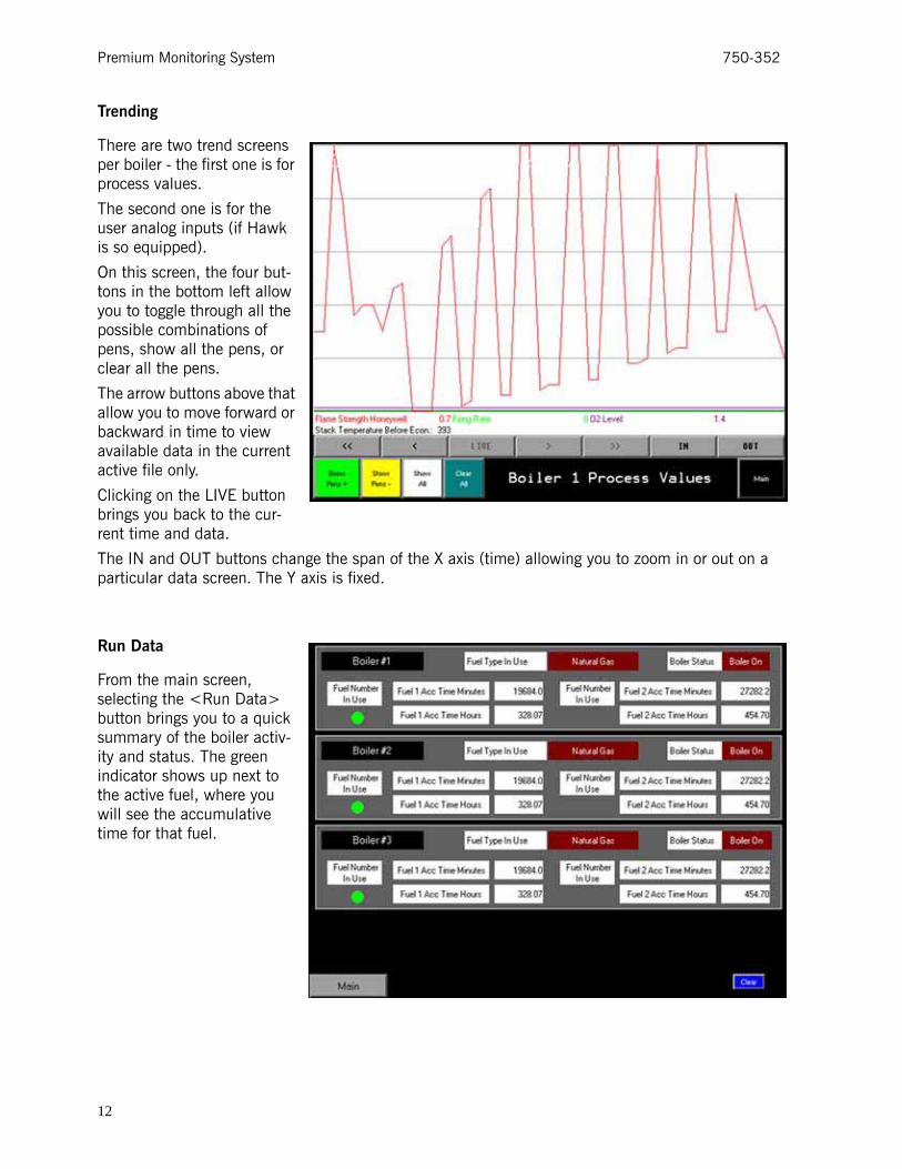
Trending
There are two trend screens per boiler - the first one is for process values.
The second one is for the user analog inputs (if Hawk is so equipped).
On this screen, the four but-tons in the bottom left allow you to toggle through all the possible combinations of pens, show all the pens, or clear all the pens.
The arrow buttons above that allow you to move forward or backward in time to view available data in the current active file only.
Clicking on the LIVE button brings you back to the cur-rent time and data.
The IN and OUT buttons change the span of the X axis (time) allowing you to zoom in or out on a particular data screen. The Y axis is fixed.
Run Data
From the main screen, selecting the <Run Data> button brings you to a quick summary of the boiler activ-ity and status. The green indicator shows up next to the active fuel, where you will see the accumulative time for that fuel.
12

750-352 Premium Monitoring System
Data Log Screen
When you first access the web server, you will see this screen. To return to this screen at any time, click on the BACK button in your web browser.
View Logs
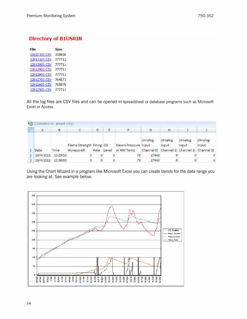
This display allows you to select and download a log file as a CSV file that can be reviewed and mod-ified in a program like Microsoft Excel. The directory provides a listing of all the available types of logs. The available data logs that have been set up for each boiler are User Analog inputs, System Data, and Flow Total Data.
Once you click on a folder in that directory, you will see all the available files for that type of log. Note they are all identified by time and date. For example 12020100 means 12th year, second month, first day starting at midnight.
13
Premium Monitoring System 750-352
All the log files are CSV files and can be opened in spreadsheet or database programs such as Microsoft Excel or Access.
Using the Chart Wizard in a program like Microsoft Excel you can create trends for the data range you are looking at. See example below.
14

750-352 Premium Monitoring System
PARTS
CB-PTWS 833-05000-000
Qty Part Description CB PN
2 Terminal Block, 832-02247-000
2 Terminal Block, End Anchor, 832-02248-000
1 Enclosure, 20"x20"x6" 848-00482-000
1 24V DC Power Supply 832-02037-000
1 Use this hub for 2-3 Boilers (4 port) 833-02862-000
0 Use this hub if 4 or more boilers are used. (8 port) 833-02857-000
1 CB Web Server 833-03718-000
15

Premium Monitoring System 750-352
www.cleaverbrooks.com
16