model computations on the differential scattering of circularly polarized light (cids) by dense...
TRANSCRIPT
Model Computations on the Differential Scattering of Circularly Polarized Light (CIDS)
by Dense Macromolecular Particles
DAVID KELLER, Department of Chemistry, University of California, Berkeley, California 94720; CARLOS BUSTAMANTE, Department of
Chemistry, University of New Mexico, Albuquerque, New Mexico 87131 ; MARCOS F. MAESTRE, Lawrence Berkeley Laboratory,
Biology and Medicine Division, University of California, Berkeley, California 94720; and IGNACIO TINOCO, JR., Department of Chemistry, University of California, Berkeley, California 94720
Synopsis
Circular intensity differential scattering (CIDS) patterns have been calculated for two general types of chiral arrangements. The calculations were done using the second Born approximation. The geometries considered are (a) a linear array of anisotropic scattering groups with a spiraling orientation (a twisted ladder) and (b) a helical array of scattering groups with arbitrary anisotropy and orientation. The CIDS expressions for the first of these models (twisted ladder) reduces to a simple analytical form and clearly illustrates many properties of CIDS patterns. The second geometry (helix) is more general. Cal- culations were done for oriented scatterers and for rotationally averaged scatterers as would be found in solution.
INTRODUCTION
Circular dichroism and optical rotatory dispersion (ORD) are two techniques that have frequently been used to obtain structural infor- mation in biological systems. Both of these techniques are forms of optical activity, that is, they both depend on the ability of chiral mol- ecules to interact preferentially with either right- or left-circularly polarized light. CD and ORD depend on the relation between the chiral structure of the sample and the handedness of circularly polarized light. This is what gives optically active techniques their sensitivity to the conformation of biological macromolecules.
In CD and ORD, we measure the difference in the ability of the sample to attenuate or refract right- and left-circularly polarized light. If the sample is a large biological aggregate, like a chromosome or bacteriophage, light will be scattered significantly as well as absorbed and refracted. In particular, if the sample is chiral, it will preferen- tially scatter right- or left-circularly polarized light. This scattering optical activity has been termed circular intensity differential scat- tering (CIDS).'
Biopolymers, Vol. 24, 783-797 (1985) @ 1985 John Wiley & Sons, Inc. CCC 0006-3525/85/050783-15$04.00
784 KELLER ET AL.
In a CIDS experiment the scattering intensity in a given direction is measured when right- and left-circularly polarized light are incident on the sample. The CIDS is defined as the difference in these two intensities divided by their sum:
where 8 and + are the polar and azimuthal angles that define the direction of the detector with respect to the direction of the incident light.
The CIDS pattern generated in this manner is sensitive to the chiral structure of the sample, with dimensions similar to the wavelength of the incident light.= If visible or uv wavelengths are used, this means that the CIDS pattern reflects structure on the order of several thou- sand angstroms. This sensitivity to long-range structure is unlike CD, which is sensitive mainly to structure on the molecular level,6 and makes CIDS well suited to the study of large biological systems. Re- cently, the CIDS patterns of the helical sperm cell of the Mediterra- nean octopus Eledone cirrhosa have been 0btained.I The CIDS patterns of T2 and T4 bacteriophages have also been measured.8
THEORY
A very general theory of the scattering of arbitrarily polarized light by a randomly oriented polymer solution has been presented by Harris, McClain, and S10an.~ They consider all components of the Stokes vec- tors of the incident and scattered beams. We have explicitly derived expressions for the CIDS of chiral molecules in the second Born ap- proximation.1° The theory is similar to that of Harris and McClain but begins from a somewhat different starting point and makes dif- ferent approximation~.*-~J~J~ In this theory, the scattering system is considered to be a collection of small polarizable scattering groups that are allowed to interact with each other. The interactions between scattering groups are (1) a short-ranged coupling between dipole mo- ments induced in the groups by the action of the incident light and (2) multiple scattering, which is effectively a long-range radiation cou- pling effect. The second Born approximation is therefore necessary for systems whose individual scattering groups are closely spaced or whose group polarizabilities are large enough to introduce significant mul- tiple scattering contributions.
The addition of the second Born approximation has revealed several properties of the CIDS patterns that did not appear in earlier calcu- l a t i o n ~ , ~ ~ J ~ where coupling between groups was not taken into account. Some of the new properties are:
1. CIDS is present in the forward direction (parallel to the incident

DIFFERENTIAL SCATTERING OF LIGHT 785
light). This forward CIDS can be shown to be due to phase shifts introduced in the forward scattering amplitudes by the coupling.%"
2. Systems composed entirely of isotropic scattering groups exhibit CIDS. In the absence of coupling, a necessary condition for CIDS to exist is that the polarizable groups have a n intrinsic anisotropy. In the present case, however, the coupling provides the anisotropy nec- essary for CIDS.SJo
3. When the coupling between the scattering groups is neglected, it is possible to find certain orientations of the scatterer for which the CIDS patterns are symmetric with respect to the incident beam, despite the intrinsic asymmetry of the chiral object. No such symmetry can be found when the coupling is included in the calculations.1°
These results should be useful in the interpretation of experimental CIDS measurements.
To obtain a more complete picture of the CIDS behavior, it is useful to carry out detailed calculations for particular model geometries. Recently, McClain et a1.12 made model calculations for point polariz- abilities, which do not include interaction between scattering groups, for a variety of scattering geometries. In this paper, we consider first a linear array of polarizable point groups whose polarizability axes twist as one proceeds down the axis of the array (a twisted ladder). This geometry can be considered a model for the CIDS of a cholesteric liquid ~rysta1. l~ The calculated CIDS expression for this model has a simple analytical form that shows various properties of the CIDS pat- terns clearly. We then consider a general helical array that allows us to investigate questions that cannot be addressed by the first model. Finally, we consider the CIDS of an arbitrary helix that has been averaged over all orientations. This can be considered as a rough model for the CIDS of a helical chromosome in solution.
The general CIDS expressions for systems composed of collections of small, polarizable groups in any geometry may be found in Refs. 2 and 5, for the CIDS of systems of noninteracting groups and in Ref. 10 for systems made of interacting groups.
Twisted Ladder
Consider the array shown in Fig. l(a). In this structure the scattering points have been arranged on a line parallel to the z-axis, and the principal axes of the polarizabilities of the groups are arranged in a spiral fashion. For the nth group of this system, the polarizability is
^ ^
a, = at,t, with
in = c o s ( p ) f 27rn Az + sin(,-jj. 27rnAz
786 KELLER ET AL.
a
/
b
Y
/ X X
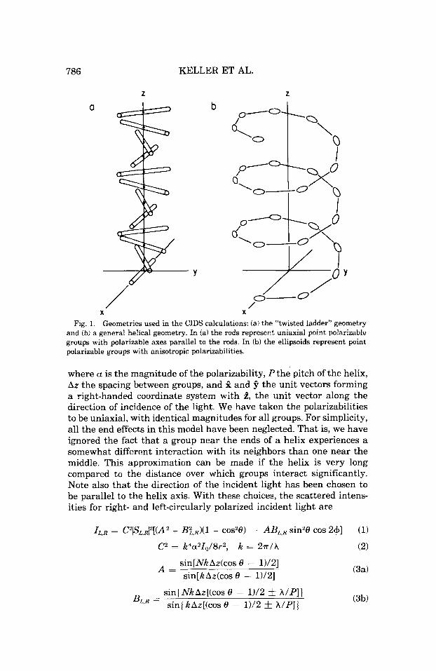
Fig. 1. Geometries used in the CIDS calculations: (a) the “twisted ladder” geometry and (b) a general helical geometry. In fa) the rods represent uniaxial point polarizable groups with polarizable axes parallel to the rods. In 6) the ellipsoids represent point polarizable groups with anisotropic polarizabilities.
where a is the magnitude of the polarizability, P the pitch of the helix, Az the spacing between groups, and f and 4 the unit vectors forming a right-handed coordinate system with 2, the unit vector along the direction of incidence of the light. We have taken the polarizabilities to be uniaxial, with identical magnitudes for all groups. For simplicity, all the end effects in this model have been neglected. That is, we have ignored the fact that a group near the ends of a helix experiences a somewhat different interaction with its neighbors than one near the middle. This approximation can be made if the helix is very long compared to the distance over which groups interact significantly. Note also that the direction of the incident light has been chosen to be parallel to the helix axis. With these choices, the scattered intens- ities for right- and left-circularly polarized incident light are
sin[NkAz(cos 8 - 11/21 sin[kAz(cos 8 - 11/21
A =
sin{NkAz[(cos 8 - 1112 f WP]) sinjkAz[(cos 8 - 1Y2 L- A/P]I BL,R =
(3a)
(3b)
DIFFERENTIAL SCATTERING OF LIGHT 787
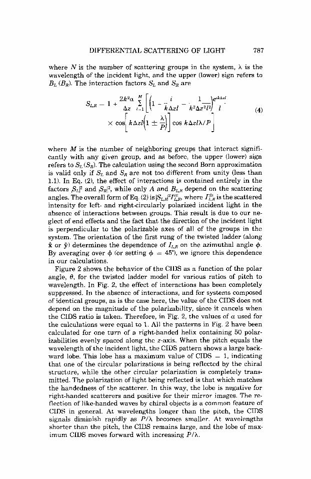
where N is the number of scattering groups in the system, A is the wavelength of the incident light, and the upper (lower) sign refers to B L ( B R ) . The interaction factors S, and SR are
i 1 eikAzl
‘L.R = + 2K2a c [ ( l + - khzl - G ) T - - - (4) Az i = i
1 where M is the number of neighboring groups that interact signifi- cantly with any given group, and as before, the upper (lower) sign refers to SL (S,). The calculation using the second Born approximation is valid only if SL and SR are not too different from unity (less than 1.1). In Eq. (21, the effect of interactions is contained entirely in the factors (SLI2 and 1SRI2, while only A and B L , R depend on the scattering angles. The overall form of Eq. (2) is IS,,l21f,k, where 1:’ is the scattered intensity for left- and right-circularly polarized incident light in the absence of interactions between groups. This result is due to our ne- glect of end effects and the fact that the direction of the incident light is perpendicular to the polarizable axes of all of the groups in the system. The orientation of the first rung of the twisted ladder (along 2 or 3) determines the dependence of IL,R on the azimuthal angle 4. By averaging over 4 (or setting 4 = 45”), we ignore this dependence in our calculations.
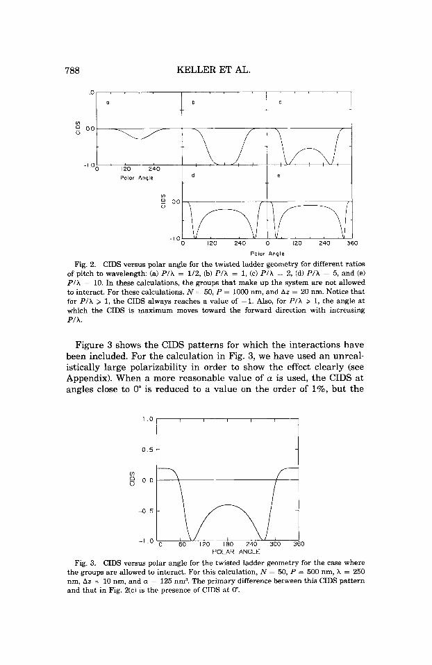
Figure 2 shows the behavior of the CIDS as a function of the polar angle, 8, for the twisted ladder model for various ratios of pitch to wavelength. In Fig. 2, the effect of interactions has been completely suppressed. In the absence of interactions, and for systems composed of identical groups, as is the case here, the value of the CIDS does not depend on the magnitude of the polarizability, since it cancels when the CIDS ratio is taken. Therefore, in Fig. 2, the values of a used for the calculations were equal to 1. All the patterns in Fig. 2 have been calculated for one turn of a right-handed helix containing 50 polar- izabilities evenly spaced along the z-axis. When the pitch equals the wavelength of the incident light, the CIDS pattern shows a large back- ward lobe. This lobe has a maximum value of CIDS = 1, indicating that one of the circular polarizations is being reflected by the chiral structure, while the other circular polarization is completely trans- mitted. The polarization of light being reflected is that which matches the handedness of the scatterer. In this way, the lobe is negative for right-handed scatterers and positive €or their mirror images. The re- flection of like-handed waves by chiral objects is a common feature of CIDS in general. At wavelengths longer than the pitch, the CIDS signals diminish rapidly as P / h becomes smaller. At wavelengths shorter than the pitch, the CIDS remains large, and the lobe of max- imum CIDS moves forward with increasing PIA.
788 KELLER ET AL.
Polar Angle
0 120 240 0 120 240 360
Polar Angle
Fig. 2. CIDS versus polar angle for the twisted ladder geometry for different ratios of pitch to wavelength: (a) PlA = 1/2, (b) P/A = 1, (c) PIA = 2, (d) PlA = 5, and (e) P/A = 10. In these calculations, the groups that make up the system are not allowed to interact. For these calculations, N = 50, P = 1000 nm, and Az = 20 nm. Notice that for P/A > 1, the CIDS always reaches a value of -1. Also, for PlA > 1, the angle at which the CIDS is maximum moves toward the forward direction with increasing PIA.
Figure 3 shows the CIDS patterns for which the interactions have been included. For the calculation in Fig. 3, we have used an unreal- istically large polarizability in order to show the effect clearly (see Appendix). When a more reasonable value of a is used, the CIDS at angles close to 0" is reduced to a value on the order of 1%, but the
0.5 t
0 60 120 180 240 300 360 POLAR ANGLE
CIDS versus polar angle for the twisted ladder geometry for the case where the groups are allowed to interact. For this calculation, N = 50, P = 500 nm, A = 250 nm, Az = 10 nm, and a = 125 nm3. The primary difference between this CIDS pattern and that in Fig. 2(c) is the presence of CIDS a t 0".
Fig. 3.

DIFFERENTIAL SCATTERING OF LIGHT 789
pattern a t other angles remains unchanged. For this geometry and direction of incidence, the effect of interactions is very simple. Using Eq. (2), we obtain
where If,& is the scattered intensity when there is no interaction be- tween groups. The approximate expression on the right in Eq. (5) holds only when (lSLi2 - IS,lz)/(lSL12 + IS$) and (I?) - Ig))/(If') + 1%)) are both small. Since S, and S, do not vary with scattering angle, Eq. (5) tells us that within this approximation, the effect of interactions is merely to add a baseline shift wherever the CIDS is small. In particular, the CIDS without interactions (19) - I '#)/(If) + 19)) is zero in the forward direction (0 = 0); therefore, the quantity (IsLiz - IS,l)/(lSLlz + IS,12) is responsible for the CIDS in the forward direction. It was suggested earlier that this twisted ladder geometry might make an approximate model for the CIDS of a cholesteric liquid crystal. Recently, the CIDS of liquid crystals of several cholesteric mixtures of methylbutyl-p- cyanobiphenyl from BDH CB-15 and ZLI-1612 from Merck, have been measured as a function of the scattering angle and for different ratios of pitch/~avelength.~* It was found that the CIDS calculated using a continuous twisted ladder model in the second Born approximation, similar to the model presented here, shows good agreement with the measured CIDS values in the forward and backward scattering angles as a function of the ratio of pitch/wavelength.
General Helix
In the previous section, we considered a twisted ladderlike helix of anisotropic polarizabilities, for light incident parallel to the helix axis. In this section, we consider a more general arrangement where the helix may have a nonzero radius. We have also allowed the groups on the helix to have general, triaxial polarizabilities and have considered directions of incidence other than parallel to the helix axis. The CIDS of a general helix can be computed by straightforward applications of Eq. (2) of Ref. 10. It has not been possible to simplify the expressions significantly, and we will not present any new equations here. In performing calculations with finite helices, we have not neglected end effects. The geometry of a general helix also provides the possibility of investigating the CIDS of a system composed entirely of isotropic scattering groups, a case for which the CIDS is zero for the geometry in the previous section.
790 KELLER ET AL.
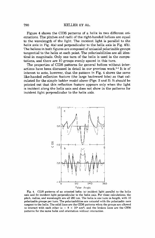
Figure 4 shows the CIDS patterns of a helix in two different ori- entations. The pitches and radii of the right-handed helices are equal to the wavelength of the light. The incident light is parallel to the helix axis in Fig. 4(a) and perpendicular to the helix axis in Fig. 4@). The helices in both figures are composed of uniaxial polarizable groups tangential to the helix a t each point. The polarizabilities are all iden- tical in magnitude. Only one turn of the helix is used in the compu- tations, and there are 10 groups evenly spaced in this turn.
The properties of CIDS patterns for general helices without inter- actions have been discussed in detail in our previous It is of interest to note, however, that the pattern in Fig. 4 shows the same like-handed reflection feature (the large backward lobe) as that cal- culated for the simple ladder model above (Figs. 2 and 3). It should be pointed out that this reflection feature appears only when the light is incident along the helix axis and does not show in the patterns for incident light perpendicular to the helix axis.
0 120 240 360
Polar Angle
-1.0
Fig. 4. CIDS patterns of an oriented helix: (a) incident light parallel to the helix axis and (b) incident light perpendicular to the helix axis. For these calculations, the pitch, radius, and wavelength are all 250 nm. The helix is one turn in length, with 10 polarizable groups per turn. The polarizabilities are uniaxial with the polarizable axes tangent to the helix. The solid lines are the CIDS patterns when the groups are allowed to interact with each other (a = 8 x lo4 nm?, and the broken lines are the CIDS patterns for the same helix and orientation without interaction.
DIFFERENTIAL SCATTERING OF LIGHT 791
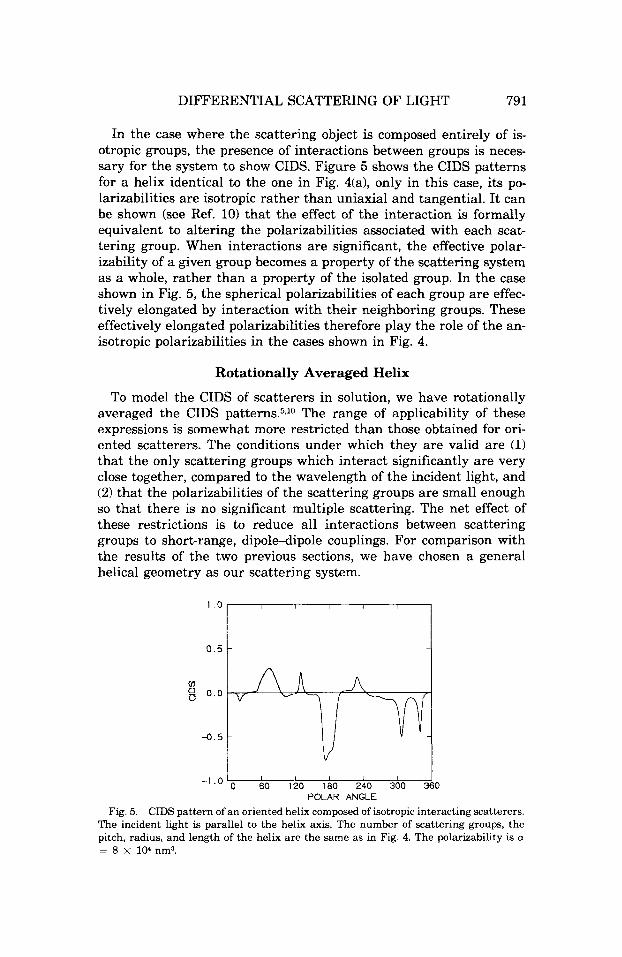
In the case where the scattering object is composed entirely of is- otropic groups, the presence of interactions between groups is neces- sary for the system to show CIDS. Figure 5 shows the CIDS patterns for a helix identical to the one in Fig. 4(a), only in this case, its po- larizabilities are isotropic rather than uniaxial and tangential. It can be shown (see Ref. 10) that the effect of the interaction is formally equivalent to altering the polarizabilities associated with each scat- tering group. When interactions are significant, the effective polar- izability of a given group becomes a property of the scattering system as a whole, rather than a property of the isolated group. In the case shown in Fig. 5, the spherical polarizabilities of each group are effec- tively elongated by interaction with their neighboring groups. These effectively elongated polarizabilities therefore play the role of the an- isotropic polarizabilities in the cases shown in Fig. 4.
Rotationally Averaged Helix
To model the CIDS of scatterers in solution, we have rotationally averaged the CIDS pattern~.~JO The range of applicability of these expressions is somewhat more restricted than those obtained for ori- ented scatterers. The conditions under which they are valid are (1) that the only scattering groups which interact significantly are very close together, compared to the wavelength of the incident light, and (2) that the polarizabilities of the scattering groups are small enough so that there is no significant multiple scattering. The net effect of these restrictions is to reduce all interactions between scattering groups to short-range, dipole-dipole couplings. For comparison with the results of the two previous sections, we have chosen a general helical geometry as our scattering system.
I I I I I I 0 60 120 180 240 300 360
CIDS pattern of an oriented helix composed of isotropic interacting scatterers. The incident light is parallel to the helix axis. The number of scattering groups, the pitch, radius, and length of the helix are the same as in Fig. 4. The polarizability is a = 8 x lo4 nm3.
- 1 .o ' POLAR ANGLE
Fig. 5.

792 KELLER ET AL.
Figure 6 shows the rotationally averaged CIDS patterns of a helix with pitch and radius identical to that in Fig. 4. The helix in Fig. 6 is 20 turns in length. For the oriented helices in Fig. 4, the length has no appreciable effect on the CIDS, and the patterns of Figs. 4 and 6 can therefore be compared (see Section VII of Ref. 10). For rotationally averaged structures, the scattering is independent of the azimuthal angle, +, and depends only on the polar angle, 8. The dashed lines in Fig. 6 show the CIDS patterns with no interaction effects. The solid lines show the CIDS patterns with interactions. As in Fig. 3, we have used unrealistically large polarizabilities in order to show the effects of interactions clearly. When reasonable polarizability magnitudes are used, the difference between CIDS patterns with and without inter- actions is smaller (a change of about 5% is caused by the presence of interactions), but the patterns are otherwise very similar. The effect of interactions appears as a marked decrease in the magnitude of the CIDS but little change in the shape of the pattern. This is the opposite to the effect that interactions between groups had on the helix com- posed of isotropic groups in Fig. 5. In the latter case, the groups were initially completely isotropic, and the effect of interactions was to make them appear somewhat anisotropic. In the present case, the groups are initially completely anisotropic and the effect of interac- tions is to make them appear more spherical. This reduction in the anisotropy of the groups is also visible in the CIDS patterns of the oriented helices in Fig. 4.
A comparison of the patterns in Fig. 6 with the corresponding pat- terns in Fig. 4 shows little resemblance between the CIDS of a rota- tionally disordered system and the CIDS of the same system in a
0.5 l-----7
-0 .5 t i ~
0 60 120 180 240 300 360 -1 . o POLAR ANGLE
Fig. 6. Rotationally averaged CIDS pattern of a helix. Broken lines indicate the CIDS pattern when no interactions are present and solid lines indicate the CIDS pattern with interactions. The pitch and radius are the same as in Fig. 4. The polarizabiiities are uniaxial and tangent to the helix. For the pattern where interactions are present, a = 1.25 x lo6 nm3. The helix is 20 turns in length, 10 groups per turn.
DIFFERENTIAL SCATTERING OF LIGHT 793
particular orientation. This is not surprising, since the averaged CIDS patterns are superpositions of the CIDS patterns from all possible orientations of the scattering system and need not resemble any one orientation. The averaged CIDS patterns are generally smaller in mag- nitude and have more zeros, maxima, and minima than the CIDS patterns for oriented systems. Both of these results are a consequence of the fact that the differential intensity, IL - I,, can be both positive and negative. The superposition of many patterns will tend to diminish the overall magnitude of the CIDS and break up any smooth regions in the patterns. There does not seem to be any tendency for rotationally averaged helices to preferentially scatter circularly polarized light of like-handedness in the back direction (see the previous discussion), and therefore, the “reflection” lobes present in Figs. 14(a) and 5 are absent in Fig. 6.
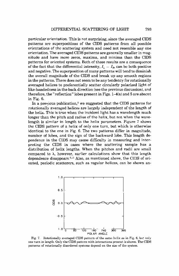
In a previous p~bl icat ion,~ we suggested that the CIDS patterns for rotationally averaged helices are largely independent of the length of the helix. This is true when the incident light has a wavelength much longer than the pitch and radius of the helix, but not when the wave- length is similar in length to the helix parameters. Figure 7 shows the CIDS pattern of a helix of only one turn, but which is otherwise identical to the one in Fig. 6. The two patterns differ in magnitude, number of lobes, and the sign of the backward lobe. This length de- pendence in the CIDS may cause difficulty in measuring and inter- preting the CIDS in cases where the scattering sample has a distribution of helix lengths. When the pitches and radii are small compared to A, however, earlier calculations show that this length dependence d i s a p ~ e a r s . ~ J ~ Also, as mentioned above, the CIDS of ori- ented, periodic scatterers, such as regular helices, can be shown an-
0.5
0 60 120 180 240 300 360 - I . o POLAR ANGLE
Rotationally averaged CIDS pattern of the same helix as in Fig. 6, but only one turn in length. Only the CIDS pattern with interactions present is shown. The CIDS
Fig. 7.
patterns of rotationally disordered systems depend on the size of the system

794 KELLER ET AL.
alytically to be largely independent of the number of repeated unit cells (helical turns) if the interactions between scattering groups in the system are not too long-ranged.
Recently, Zietz et al.15 have published calculated CIDS patterns of the solenoidal model of chromatin.16J7 These authors assume spherical polarizabilities for the histone-DNA complex and obtain the rotation- ally averaged CIDS of the solenoid, taking into account all orders of interaction of the induced dipoles. They use the method of Purcell and Pennypacker,lB which uses a lattice of interacting spherical dipole oscillators to approximate the scattering cross sections of an irregu- larly shaped object. Unfortunately, the authors do not present the magnitudes of the CIDS ratios. We have done an equivalent calculation using Purcell and Pennypacker's method for oriented chromatin so- lenoids. We have found that the CIDS ratio expected from these sys- tems is of the order of a number that could possibly be measured with the current available instrumentation.
DISCUSSION AND CONCLUSIONS
We have presented the CIDS patterns calculated for (a) a twisted ladder, (b) oriented helices made up of point polarizable groups with two different orientations with respect to the incident light, and (c) rotationally disordered helices with parameters as in (b).
For oriented systems, when the incident light propagates down the ladder or the helix axis, and the pitch of the helix is close to the wavelength of light, only one of the circular polarizations of the light is reflected, giving rise to a large backward lobe in the CIDS. The polarization reflected matches the handedness of the helix, so that the CIDS in the backward direction is close to - 1 for a right-handed helix and +1 for a left-handed helix. This reflection effect attains a maxi- mum when PIA = 1. This behavior has been observed experimentally in the light scattered by cholesteric liquid crystals and has been found theoretically in macroscopic models of the optical properties of liquid ~rysta1s.l~ In the case of the ladder model at wavelengths longer than the pitch, the CIDS signals diminish rapidly as Plh becomes smaller. At wavelengths shorter than the pitch, the CIDS remains large and the lobe of maximum CIDS moves forward with increasing P/A.
When multiple scattering effects and interactions between the groups in the scatterer are taken into account, forward differential scattering intensities are calculated. In the context of the approxi- mations used in this paper (see also Ref. lo), this forward CIDS appears only for oriented systems. Less severe approximations would result in forward CIDS for rotationally averaged systems as well. In principle, it should be possible to differentiate the forward CIDS signals (which are independent of the concentration of the sample) from the differ- ential transmission (CD) by varying the sample concentration and

DIFFERENTIAL SCATTERING OF LIGHT 795
extrapolating to zero con~entration. '~ The presence or absence of for- ward CIDS in an experimental measurement should therefore be an important clue to the interpretation of the CIDS signals by theoretical models.
If the scatterer is composed entirely of isotropic groups, then there can be no CIDS unless the groups interact with each other.%" When the groups do interact with each other, the net effect is to add some anisotropy to the polarizabilities. The CIDS patterns of systems of interacting isotropic groups are quite similar to the CIDS patterns of systems of noninteracting anisotropic groups.
For rotationally averaged systems, the averaging process tends to decrease the magnitude of the differential intensity while increasing the number of lobes of alternating sign in the patterns. This decrease in magnitude and increase in structure results from the superposition of patterns of different positive and negative differential intensity distribution, corresponding to different orientations of the system with respect to the incident light. Within the approximations used in these calculations, rotationally averaged scatterers made up of spherically symmetric polarizabilities will not show CIDS. This defect can also be remedied by the use of less severe approximation^.^
In rotationally averaged systems, the CIDS is approximately inde- pendent of the length of the helix when the wavelength of light is much larger than the pitch and radius of the helix, i.e., larger than the chiral unit cell of the scattering system. However, if the dimensions of the chiral unit cell are larger than, or similar to, the wavelength of light, this insensitivity to the total size of the particle is lost.
In general, for both oriented and rotationally disordered systems, the effect of the interaction between the groups in the scatterer is to modify (increase or decrease) the anisotropy of the effective polariz- ability of the scattering groups in the molecule. So far, relatively few systems have been studied using the CIDS technique, but the results of these studies are encouraging. The CIDS measurements made on cholesteric liquid crystals have been quantitatively matched by cal- culations using a model similar to the twisted ladder model presented here,l4pZ0 at least for scattering angles close to 0" and 180". Preliminary calculations have also been made for the helical sperm cell of the mediterranean octopus, Eledona cirrhosa, and these show at least qual- itative agreement with the measured CIDS7 for the same system.
These results, together with the calculations presented here, indicate that circular differential scattering is a technique specially suited to give information about the long-range structure of chiral scatterem when the incident radiation falls in the uv or visible range of the spectrum. This sensitivity to long-range structure makes CIDS a useful method to follow conformational changes such as those undergone by chromatin along the cell cycle. Although in a system as complex as the superorganization of chromatin the information obtained will nec-
KELLER ET AL.
essarily be of a qualitative nature, a number of features of the CIDS patterns can be understood quite simply in terms of the structure of the scattering particle. In principle, the available CIDS theory allows the fitting of models of chiral scatterers to the differential scattering data and provides structural information about the chiral particle.
APPENDIX
In order to obtain reasonable estimates of polarizability magnitudes, we have used the Clausius-Mosotti formula
( E - U / ( E + 2) = 47rNa/3
Here, E is the effective dielectric constant of the scatterer relative to the solvent, N the number of scatterers per unit volume, and a the effective polarizability of the scatterer. For a sphere of radius r and volume N-l , its polarizability is
a = ( E - l ) r 3 / ( ~ + 2)
Thus, for an effective dielectric constant of c = 1.4, and a radius of 88 nm, an effective polarizability of a = 8 X lo4 nm3 is obtained.
This work was supported in part by National Institutes of Health Grants GM 10840 (I.T.), A1 08247 (M.F.M.), and GM 32543 (C.B.), and by the US. Department of Energy, Office of Energy Research Contract DEAT03-82-ER60090. This work was also supported in part by a 1984 Searle Scholarship granted to one of the authors (C.B.).
References 1. Barron, L. D. & Buckingham, A. D. (1971) Mol. Phys. 20, 1111-1119. 2. Bustamante, C., Maestre, M. F. & Tinoco, Jr . , I. (1980) J. Chem. Phys. 73, 4273-
4281. 3. Bustamante, C., Maestre, M. F. & Tinoco, Jr., I. (1980) J. Chem. Phys. 73, 6046-
6055. 4. Bustamante, C., Tinoco, Jr., I. & Maestre, M. F. (1981) J. Chem. Phys. 74, 4839-
4850. 5. Bustamante, C., Tinoco, Jr., I. & Maestre, M. F. (1982) J. Chem. Phys. 76, 3440-
3446. 6. Tinoco, Jr., I., Bustamante, C. & Maestre, M. F. (1980) Annu. Rev. Biophys. Bioeng.
9, 107-141. 7. Maestre, M. F., Bustamante, C., Hayes, T. L., Subirana, J. A. & Tinoco, Jr., I.
(1982) Nature 298, 773-774. 8. Tinoco, Jr., I., Bustamante, C. & Maestre, M. F. (1982) in Structural Molecular
Biology: Methods and Applications, Davies, D. B., Saenger, W. & Danyluk, S. S., Eds., Plenum Press, New York.
9. Harris, R. A,, McClain, W. M. & Sloane, C. F. (1974) Mol. Phys. 28, 381-398. 10. Bustamante, C., Maestre, M. F., Keller, D. & Tinoco, Jr., I. (1984) J. Chem. Phys.
11. Bustamante, C. (1980) Ph.D. Thesis, Chemistry Department, University of Cali- 80, 48174823.
fornia, Berkeley.
DIFFERENTIAL SCATTERING OF LIGHT 797
12. McClain, W. M., Schauerte, J . A. & Harris, R. A. (1984) J. Chem. Phys. 80, 606- 616.
13. Chandrasekhar, S. (1977) Liquid Crystah, Cambridge University Press, Cambridge, Chap. 4.
14. Bustamante, C., Wells, K. S., Keller, D., Samori, B., Maestre, M. F. & Tinoco, Jr., I. (1984) Mol. Cryst. Liq. Cryst. 111, 79-102.
15. Zietz, S., Belmont, A. & Nicolini, C. (1983) Cell Biophys. 5, 163-187. 16. Finch, J . & Klug, A. (1976) Proc. Natl. Acad. Sci. USA 73, 1897. 17. Igo-Kemenes, Horz, W. & Zachau, H. (1982) Annu. Rev. Biochem. 51, 89-121. 18. Purcell, E. M. & Pennypacker, C. R. (1973) Astrophys. J . 186, 705-714. 19. Bustamante, C., Tinoco, Jr., I. & Maestre, M. F. (1983) Roc. Natl. Acad. Sci. USA
80, 3568-3572. 20. Hall, K., Wells, K. S., Keller, D., Samori, B., Maestre, M. F., Tinoco, Jr., I. &
Bustamante, C. (1985) Applications of Circularly Polarized Radiation, Allen, F. & Bus- tamante, C., Eds., Plenum Press, New York.
Received June 21, 1984 Accepted October 16, 1984