model oi-6000 sensor assembly - brandt … · introduction this document is an operation manual...
TRANSCRIPT

Model OI-6000 Sensor Assembly___________________________________
Operation ManualRevision 2.3.1w
______________________________________________________

Product Overview
The Otis Instruments, Inc. Model OI-6000 GenII ambient air gas sensor assembly is a wired, WireFree, or “Notis” sensor assembly that uses a Catalytic Bead, Electro-Chemical, PID, or Infrared sensor element to detect a variety of gases. The device comes standard with a 102 x 64 graphical LCD screen, Otis Instruments standard three-button interface, Otis-blue custom explosion-proof enclosure, and non-intrusive magnetic switches.
The OI-6000 Sensor Assembly is an innovative wired or wireless gas detection system designed to monitor gas in hostile environments without the use of wires or conduit from the controller to the sensor. The OI-6000 features 4-20mA (3-wire) or RS-485 Modbus output, and can be customized to offer relay and radio (900MHz or 2.4GHz) options.
The OI-6000 Sensor Assembly's key feature is non-intrusive calibration and configuration. With all adjustments made at the sensor assembly, one-man non-intrusive calibration is quick, easy, and allows the sensor housing and enclosure to remain Class I, Division 1, Group C and D certified while in the field. Non-intrusive calibration is made possible by using an Otis Instruments, Inc. distributed magnet to activate the MENU, ADD, and SUB buttons.
The device has been designed to reject EMI and other forms of interference in order to avoid false gas readings.
Features such as the auto-setting Null, relay/alarm tests, and system diagnostics make this device a truly remarkable gas detection system.
2

Table of ContentsProduct Overview.......................................................................................................................................2Introduction................................................................................................................................................ 5Warnings..................................................................................................................................................... 5Complete System Diagram........................................................................................................................ 6
Complete System (External)...............................................................................................................................................6Complete System (Internal)............................................................................................................................................... 7
Wiring Configurations...............................................................................................................................8Power Supply Configuration............................................................................................................................................. 8Relays/Alarms Configurations.........................................................................................................................................11
DC Relays/Alarms Configuration – Preparation Steps.................................................................................................12DC Relay Configurations – Relay 1 Power.................................................................................................................. 12DC Alarm Configurations – Alarm 1 to Relay 1.......................................................................................................... 13DC Relay Configurations – Relay 2 Power.................................................................................................................. 13DC Alarm Configurations – Alarm 2 to Relay 2.......................................................................................................... 14DC Relays/Alarms Configurations – Completion Steps...............................................................................................14AC Relays/Alarms Configuration – Preparation Steps.................................................................................................15AC Relay/Alarm Configurations – Relay/Alarm 1.......................................................................................................16AC Relay/Alarm Configurations – Relay/Alarm 2.......................................................................................................17AC Relays/Alarms Configurations – Completion Steps...............................................................................................18Connecting 4-20mA .....................................................................................................................................................19Connecting Modbus .....................................................................................................................................................20Using Modbus Sensors with Otis Instruments, Inc. Monitors......................................................................................21
Power On (from Power Off Mode)......................................................................................................... 24Power Off ................................................................................................................................................. 26Basic Menu Mode ....................................................................................................................................28
Nulling the Sensor............................................................................................................................................................28Calibration........................................................................................................................................................................31Setting Low Alarm............................................................................................................................................................34Setting High Alarm.......................................................................................................................................................... 36Setting Radio Address...................................................................................................................................................... 37
Advanced Menu Mode.............................................................................................................................38Relays/Alarms Test Setting ..............................................................................................................................................38Setting Network ID ..........................................................................................................................................................39Diagnostics....................................................................................................................................................................... 40Unit Info........................................................................................................................................................................... 41Background Gas Setting ................................................................................................................................................ 42Relay 1: Latching/Unlatching......................................................................................................................................... 43Relay 2: Latching/Unlatching......................................................................................................................................... 44Setting Modbus Address...................................................................................................................................................45Setting Baud..................................................................................................................................................................... 45Set 4-20mA Offset?...........................................................................................................................................................46Set 4-20mA Offset (Low).................................................................................................................................................. 47Set 4-20mA Offset (High).................................................................................................................................................48Setting LCD Contrast....................................................................................................................................................... 49Restore to Factory Default...............................................................................................................................................50
Antenna Replacement (WireFree Applications Only).......................................................................... 52Appendix A: O2 Sensor Information.....................................................................................................54
Null................................................................................................................................................................................... 55Background Gas Setting.................................................................................................................................................. 55Relay Settings................................................................................................................................................................... 55
3

Exiting Menu Mode......................................................................................................................................................... 55Response Time..................................................................................................................................................................55O2 Percentile Range.........................................................................................................................................................55
Appendix B: OI-6000 Troubleshooting Guide......................................................................................56Appendix C: Sensor Temperature Ranges............................................................................................58Appendix D: 4-20mA Current Loop Information................................................................................60
Overview........................................................................................................................................................................... 61Calculations......................................................................................................................................................................61Measuring Current...........................................................................................................................................................62
Specifications............................................................................................................................................ 63
4

Introduction
This document is an Operation Manual containing diagrams and step-by-step instruction for proper operation of the Otis Instruments, Inc. WireFree Model OI-6000 Sensor Assembly. This document should be read before initial operation of the product.
Should a question arise during the use of the product, this document will serve as a first reference for consultation. If further questions arise, or if the device is not working properly, please contact the sales representative of this product.
Warnings
• CAUTION: FOR SAFETY REASONS THIS EQUIPMENT MUST BE OPERATED AND SERVICED BY QUALIFIED PERSONNEL ONLY. READ AND UNDERSTAND INSTRUCTION MANUAL COMPLETELY BEFORE OPERATING OR SERVICING.
• ATTENTION : POUR DES RAISONS DE SÉCURITÉ, CET ÉQUIPEMENT DOIT ÉTRE UTILISÉ ENTRETENU ET RÉPARÉ UNIQUEMENT PAR UN PERSONNEL QUALIFIÉ. ÉTUDIER LE MANUEL D'INSTRUCTIONS EN ENTIER AVANT D'UTILISER, D'ENTERETENIR OU DE RÉPARER L'ÉQUIPEMENT.
• CAUTION: THIS AREA MUST BE FREE OF FLAMMABLE GASES DURING CALIBRATION IF CALIBRATION IS PERFORMED USING THE PUSH-BUTTONS WHILE THE EXPLOSION-PROOF CONTAINER IS OPEN.
• ATTENTION : CETTE ZONE DOIT ÉTRE EXEMPTE DE GAZ INFLAMMABLES PENDANT L'ÉTALONAGE.
• CAUTION: HIGH OFF-SCALE READINGS MAY INDICATE AN EXPLOSIVE CONCENTRATION.
• ONLY THE COMBUSTIBLE GAS DETECTION PORTION OF THIS INSTRUMENT HAS BEEN ASSESSED FOR PERFORMANCE.
• CAUTION: RELAYS ARE USER-SETTABLE TO LACTCHING OR UNLATCHING.
5

Complete System DiagramThe following diagrams should be consulted for identification of the system and all parts that may be referred to in this Operation Manual.
NOTE: Not all applications include relays and/or a radio (antenna).
Complete System (External)
6

Complete System (Internal)
7

Wiring ConfigurationsTo ensure full-functionality—and to maintain certification of the product—complete ALL of the following wiring configurations before installing the device in the field (a non-classified area).
Power Supply Configuration
If it is necessary to attach a new power cord to the OI-6000, the following instructions should be consulted.
NOTE: Verify that there is no power being sent from the power supply while wiring the power supply.
1. Unscrew, remove and set aside the explosion-proof Moore lid.
2. Using your thumb and forefinger, firmly grip the Front Panel Thumb-Screws and lift it out of the Moore enclosure.
NOTE: Do not use any metal object to remove the Terminal Board.
3. Lay the components on the enclosure rim so that the internal components are exposed.
4. Run the power supply cord through the hole on the upper left side (hub) of the enclosure.
5. Connect the positive wire (red) to the power supply terminal block labeled “+12-35 VDC”.
6. Connect the neutral wire (black) to the power supply terminal block labeled “GND”.
8

Power Supply Configuration cont...
7. Replace the unit back in the Moore enclosure by matching each mounting post to its corresponding eyelet inside the enclosure.
8. Verify that each mounting post is properly fitted in its corresponding eyelet inside the Moore enclosure.
9. Verify that the sealing ring (located on the threads of the open Moore enclosure) is still in place.
10. Place the Moore enclosure lid on top of the Moore enclosure base.
11. Rotate the lid until it is tightly screwed in place (approximately 20 rotations).
12. Apply +12-35 Volts DC power from the controller/monitor to the unit.
9

Power Supply Configuration cont...
13. The device will then count down from 60 to 0.
From 60 to 30, the Display Screen will show the Otis Instruments, Inc. logo.
From 30 to 0, the Display Screen will show:
14. When “0” is displayed, the device is in Normal Operating Mode and ready to operate.
NOTE: If the device is in Fault (in this example, Fault 14), the Display Screen will resemble the following illustrations:
For additional information regarding system faults, see the OI-6000 Troubleshooting Guide on page 26.
10

Relays/Alarms Configurations
The following information and instructions should be consulted for proper relay-wiring procedures.
NOTE: Not all applications include relays.
● Verify that there is no power being sent from the power supply while wiring the relays.
● The OI-6000 is DC Powered only. If AC powered alarms are desired, the user must provide their own outside AC power supply to power the relays.
● Otis Instruments, Inc. recommends wiring the relays as “NO” for most applications. With a “NO” relay, the relay will only be triggered if gas is seen.
● The user may choose to wire the relays as “NC” if desired. To do so, connect the neutral wire from the power supply to the terminal labeled “NC” (Normally Closed) instead of the terminal labeled “NO” (Normally Open).
● The wire colors used in the following drawings are used for ease of displaying which wires go where. Although the wire colors used in these drawings are standard colors, not all applications will use the same wire colors.
11

DC Relays/Alarms Configuration – Preparation Steps
1. Unscrew, remove and set aside the explosion-proof Moore lid.
2. Using your thumb and forefinger, firmly grip the Front Panel Thumb-Screws and lift it out of the Moore enclosure.
NOTE: Do not use any metal object to remove the Terminal Board
3. Lay the components on the enclosure rim so that the internal components are exposed.
DC Relay Configurations – Relay 1 Power
1. Bring the two conductor cables from the Relay 1 Alarm (light/horn) to the OI-6000 using the proper certified 3/4” NPT cable gland or conduit fitting.
2. Run the two conductor cables for Relay 1 from the Relay 1 Alarm (light/horn) through the hole (hub) on the upper left side of the OI-6000 Enclosure.
3. Connect a positive wire (red) from the terminal labeled “+12-35 VDC” on the Power Supply Terminal Block to the terminal labeled “COM” on the Relay 1 Terminal Block.
12

DC Alarm Configurations – Alarm 1 to Relay 1
1. Connect a positive wire (red) from the Relay 1 Alarm (light/horn) to the terminal labeled “NO” on the Relay 1 Terminal Block.
2. Connect a neutral wire (black) from the Relay 1 Alarm (light/horn) to the terminal labeled “GND” on the Power Supply Terminal Block.
DC Relay Configurations – Relay 2 Power
1. Bring the two conductor cables from the Relay 2 Alarm (light/horn) to the OI-6000 using the proper certified 3/4” NPT cable gland or conduit fitting.
2. Run the two conductor cables for Relay 2 from the Relay 2 Alarm (light/horn) through the hole (hub) on the upper left side of the OI-6000 Enclosure.
3. Connect a jumper wire (blue) from the terminal labeled “COM” on the Relay 1 Terminal Block to the terminal labeled “COM” on the Relay 2 Terminal Block.
13

DC Alarm Configurations – Alarm 2 to Relay 2
1. Connect a positive wire (red) from the Relay 2 Alarm (light/horn) to the terminal labeled “NO” on the Relay 2 Terminal Block.
2. Connect a neutral wire (black) from the Relay 2 Alarm (light/horn) to the terminal labeled “GND” on the Power Supply Terminal Block.
NOTE: The “Neutral” wires from Alarm 1 and Alarm 2 should be connected to occupy the same “GND” terminal on the Power Supply Terminal Block.
DC Relays/Alarms Configurations – Completion Steps
1. Replace the unit back in the Moore enclosure by matching each mounting post to its corresponding eyelet inside the enclosure.
2. Verify that each mounting post is properly fitted in its corresponding eyelet inside the Moore enclosure.
14

DC Relays/Alarms Configurations – Completion Steps
3. Verify that the sealing ring (located on the threads of the open Moore enclosure) is still in place.
4. Place the Moore enclosure lid on top of the Moore enclosure base.
5. Rotate the lid until it is tightly screwed in place (approximately 20 rotations).
AC Relays/Alarms Configuration – Preparation Steps
NOTE: The OI-6000 is DC Powered only. If AC powered alarms are desired, the user must provide their own outside AC power supply to power the relays.
1. Unscrew, remove and set aside the explosion-proof Moore lid.
2. Using your thumb and forefinger, firmly grip the Front Panel Thumb-Screws and lift it out of the Moore enclosure.
NOTE: Do not use any metal object to remove the Terminal Board
3. Lay the components on the enclosure rim so that the internal components are exposed.
15

AC Relay/Alarm Configurations – Relay/Alarm 1
1. Bring the two conductor cables from the Relay 1 Alarm (light/horn) to the Front Panel of the Radio/Relay Board using the proper certified 3/4” NPT cable gland or conduit fitting.
2. Run the two conductor cables for Relay 1 from the Relay 1 Alarm (light/horn) through the hole (hub) on the upper left side of the OI-6000 Enclosure.
3. Connect a positive wire (red) from the Relay 1 Alarm (light/horn) to the terminal labeled “NO” on the Relay 1 Terminal Block.
4. Connect a neutral wire (black) from the Relay 1 Alarm (light/horn) to the AC power supply Neutral.
5. Connect a positive wire (red) from the AC power supply to the terminal labeled “COM” on the Relay 1 Terminal Block.
16

AC Relay/Alarm Configurations – Relay/Alarm 2
1. Bring the two conductor cables from the Relay 2 Alarm (light/horn) to the Front Panel of the Radio/Relay Board using the proper certified 3/4” NPT cable gland or conduit fitting.
2. Run the two conductor cables for Relay 2 from the Relay 2 Alarm (light/horn) through the hole (hub) on the upper left side of the OI-6000 Enclosure.
3. Connect a jumper wire (blue) from the terminal labeled “COM” on the Relay 1 Terminal Block to the terminal labeled “COM” on the Relay 2 Terminal Block.
4. Connect a positive wire (red) from the Relay 2 Alarm (light/horn) to the terminal labeled “NO” on the Relay 2 Terminal Block.
5. Connect a neutral wire (black) from the Relay 2 Alarm (light/horn) to the AC power supply Neutral.
17

AC Relays/Alarms Configurations – Completion Steps
1. Replace the unit back in the Moore enclosure by matching each Back Panel mounting post to its corresponding eyelet inside the enclosure.
2. Verify that each mounting post is properly fitted in its corresponding eyelet inside the Moore enclosure.
3. Verify that the sealing ring (located on the threads of the open Moore enclosure) is still in place.
4. Place the Moore enclosure lid on top of the Moore enclosure base.
5. Rotate the lid until it is tightly screwed in place (approximately 20 rotations).
18

Connecting 4-20mA
The OI-6000 is capable of communicating as a WireFree and/or Wired sensor assembly. For wired applications, 4-20mA and/or Modbus communication will be used.
1. Locate the Power Supply Terminal Block on the Terminal Board.
2. Connect a wire (green) from the 4-20mA monitor to the terminal labeled “4-20mA” on the Power Supply Terminal Block.
19

Connecting Modbus
The OI-6000 is capable of communicating as a WireFree and/or Wired sensor assembly. For wired applications, 4-20mA and/or Modbus communication will be used.
1. Locate the Modbus Terminal Block on the Terminal Board.
2. Connect a wire (red) from the monitoring device to the terminal labeled “A” (left terminal).
3. Connect a ground (black) wire from the monitoring device to the terminal labeled “GND” (center terminal).
4. Connect a wire (green) from the monitoring device to the terminal labeled “B” (right terminal).
20
Using Modbus Sensors with Otis Instruments, Inc. Monitors
Certain monitors sold by Otis Instruments, Inc. have the capability of accepting Modbus sensor inputs. Modbus is a communication protocol that uses an RS-485 serial connection, and can accept a number of different devices.
Based on the type of circuit used, there is a limit on how many devices can be connected to a Modbus sensor network. Currently at Otis Instruments, there is a limit of 32 devices on a single network. The data is transferred along the Modbus network at a specified rate, which means that there will be a small delay proportional to the number of connections.
Proper Connection
The physical length of a Modbus connection from the monitor to the last sensor cannot exceed 4000 feet. Twisted pair is required for connections, and shielded twisted pair is recommended if there will be any additional noise in the area of operation (such as motors, switching relays, etc.). Also, with distances greater than 100ft, 18-20 gauge wire is recommended, where 22-24 gauge wire will be sufficient for short distances.
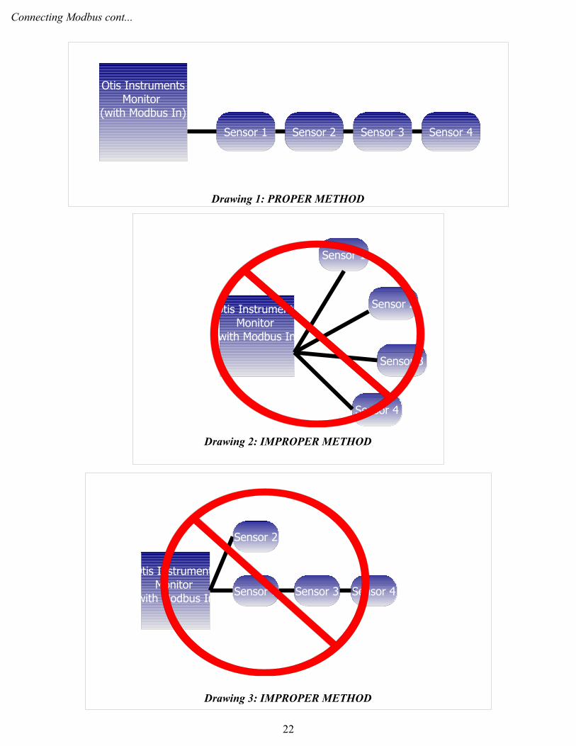
The proper way to connect a Modbus network is to “daisy-chain” the devices. This means that the signal of each sensor is run to the signal of the following sensor and so on. Each sensor is connected to the previous sensor via the signal wire, therefore the first sensor is connected directly to the monitor.
Terminating resistors should also be taken into consideration for long distances, while short and medium lengths can function normally without the resistor. Short lengths are generally less than 100ft, medium lengths range from 100-1000ft, and long lengths can be considered any distance greater than 1000ft. In the daisy-chained network, if the terminating resistor is required it should be placed at the last device in the chain.
Consult the following diagrams for proper (and improper) daisy-chain wiring methods.
21
Connecting Modbus cont...
22
Drawing 1: PROPER METHOD
Drawing 3: IMPROPER METHOD
Otis InstrumentsMonitor
(with Modbus In)Sensor 1 Sensor 3 Sensor 4
Sensor 2
Otis InstrumentsMonitor
(with Modbus In)
Sensor 1 Sensor 2 Sensor 3 Sensor 4
Drawing 2: IMPROPER METHOD
Otis InstrumentsMonitor
(with Modbus In)
Sensor 1
Sensor 2
Sensor 3
Sensor 4

Connecting Modbus cont...
Requirements Summary
Short Distances:
• Less than 100 feet
• 22-24 gauge wire
• Twisted Pairs (shielded if in area of high noise)
Medium Distances
• 101 – 1000 feet
• 18-20 gauge wire
• Twisted Pairs (shielded if in area of high noise)
Long Distances
• 1001 – 4000 feet
• 18-20 gauge wire
• Twisted Pairs (shielded if in area of high noise).
• Terminating resistors may be required (on last device in chain)
23

Power On (from Power Off Mode)Powering on the device activates its functions. When powered on, the device is fully functional and access to system and settings menus is allowed.
NOTE: If the OI-6000 is using wired power, the sensor assembly will automatically turn on when power is applied.
1. Locate ADD on the Front Panel.
2. Touch an Otis Instruments, Inc. distributed magnet to the left side of the device to activate ADD (and turn on the device).
NOTE: When the magnet touches the device and a connection has been made a trapezoid will appear.
24
Power On cont...
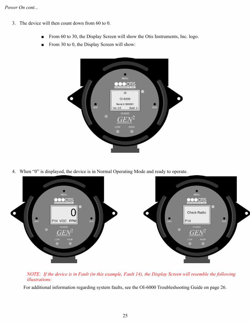
3. The device will then count down from 60 to 0.
From 60 to 30, the Display Screen will show the Otis Instruments, Inc. logo.
From 30 to 0, the Display Screen will show:
4. When “0” is displayed, the device is in Normal Operating Mode and ready to operate.
NOTE: If the device is in Fault (in this example, Fault 14), the Display Screen will resemble the following illustrations:
For additional information regarding system faults, see the OI-6000 Troubleshooting Guide on page 26.
25

Power Off Powering off the device shuts down the system. When powered off, the device is no longer transmitting signals so the receiving controller will display “FAU” for that sensor channel.
1. Locate SUB on the Front Panel.
2. Touch and hold an Otis Instruments, Inc. distributed magnet against the right side of the device for four seconds to activate the SUB button (which turns the device off).
NOTE: When the magnet touches the device and a connection is made, a trapezoid will appear on the display screen.
26

Power off cont...
3. When powering off, the display screen will switch from showing “0” to “OFF”. The display will continue to show “OFF” (when power is being supplied to the unit) until the device is powered on.
27

Basic Menu Mode The Basic Menu Mode should be used to set the basic settings of the OI-6000 before initial use, and/or to adjust the basic settings to accommodate use. Basic Menu Mode options include: Null, Calibration, Set Low Alarm, Set High Alarm, and Radio Address.
NOTE: All Basic Menu Mode options may not apply to your application (ex: radio address will not apply to applications without a radio).
Nulling the Sensor
NOTE: When using an O2 sensor, the nulled reading will be 20.9.
1. Touch an Otis Instruments, Inc. distributed magnet to the top side of the device to activate the MENU button.
2. The display screen will show:
NOTE: A message will be sent to the receiving controller indicating that the sensor is in Null Mode.
28

Nulling the Sensor cont...
3. As the Display Screen instructs, touch the magnet to ADD to auto null.
4. The Display Screen will then show:
5. Touch the magnet to ADD for “Yes” or SUB for “No”.
NOTE: If too much time elapses between when ADD is pressed and when the question regarding clean air is answered, the device will default back to the primary Null screen. If this occurs, simply touch the magnet to the ADD button again.
6. The Display Screen will show (counting down from 6-0):
29

Nulling the Sensor cont...
7. Once the sensor has been Nulled, the Display Screen will show:
8. Auto Null is complete, proceed to the next step.
30

Calibration
1. After Auto Null is complete (see above), touch an Otis Instruments, Inc. distributed magnet to the top side of the device to activate the MENU button.
2. The display screen will show:
31

Calibration cont...
3. Unscrew and remove the sensor rainguard from the sensor housing.
4. Replace the sensor rainguard with an Otis OI-410 Calibration Cup.
5. Apply a known calibration gas to the OI-410 Calibration Cup that is attached to the sensor housing.
6. The sensor's detection of gas will begin to climb in value as shown on the display screen.
7. Watch the display screen until the displayed number stops increasing (or after approximately 90 seconds).
32

Calibration cont...
8. Touch the magnet to ADD (increase) or SUB (decrease) to manipulate the reading on the display screen to match that of the calibration gas.
EXAMPLE: If the calibration gas is 25 PPM (or %) and the number on the display screen is 22 PPM (or %), touch the magnet to ADD until the screen reads 25 PPM (or %)
9. The device is now calibrated.
10. Unscrew the OI-410 Calibration Cup.
11. Reattach (screw on) the sensor rainguard to the sensor housing.
12. Once Calibration is complete, proceed to the next step.
33

Setting Low Alarm
NOTE: The maximum value that can be set for either relay is 60% of full scale concentration.
NOTE: When using an O2 sensor two relays will be available, however: Relay 1 will trigger when the reading is below the Low Alarm Set Point; Relay 2 will trigger when the reading is above the High Alarm Set Point.
1. After Calibration is complete (see above), touch an Otis Instruments, Inc. distributed magnet to the top side of the device to activate the MENU button.
2. The display screen will show:
34

Setting Low Alarm cont...
3. Touch the magnet to ADD to increase, or SUB to decrease the Low Alarm setting.
4. Once the Low Alarm is set, proceed to the next step.
35

Setting High Alarm
1. After the Low Alarm is set (see above), touch an Otis Instruments, Inc. distributed magnet to the top side of the device to activate the MENU button.
2. The display screen will show:
3. Touch the magnet to ADD to increase, or SUB to decrease the High Alarm setting.4. Once the High Alarm is set, proceed to the next step.
36
Setting Radio Address
1. After the High Alarm is set (see above), touch an Otis Instruments, Inc. distributed magnet to the top side of the device to activate the MENU button.
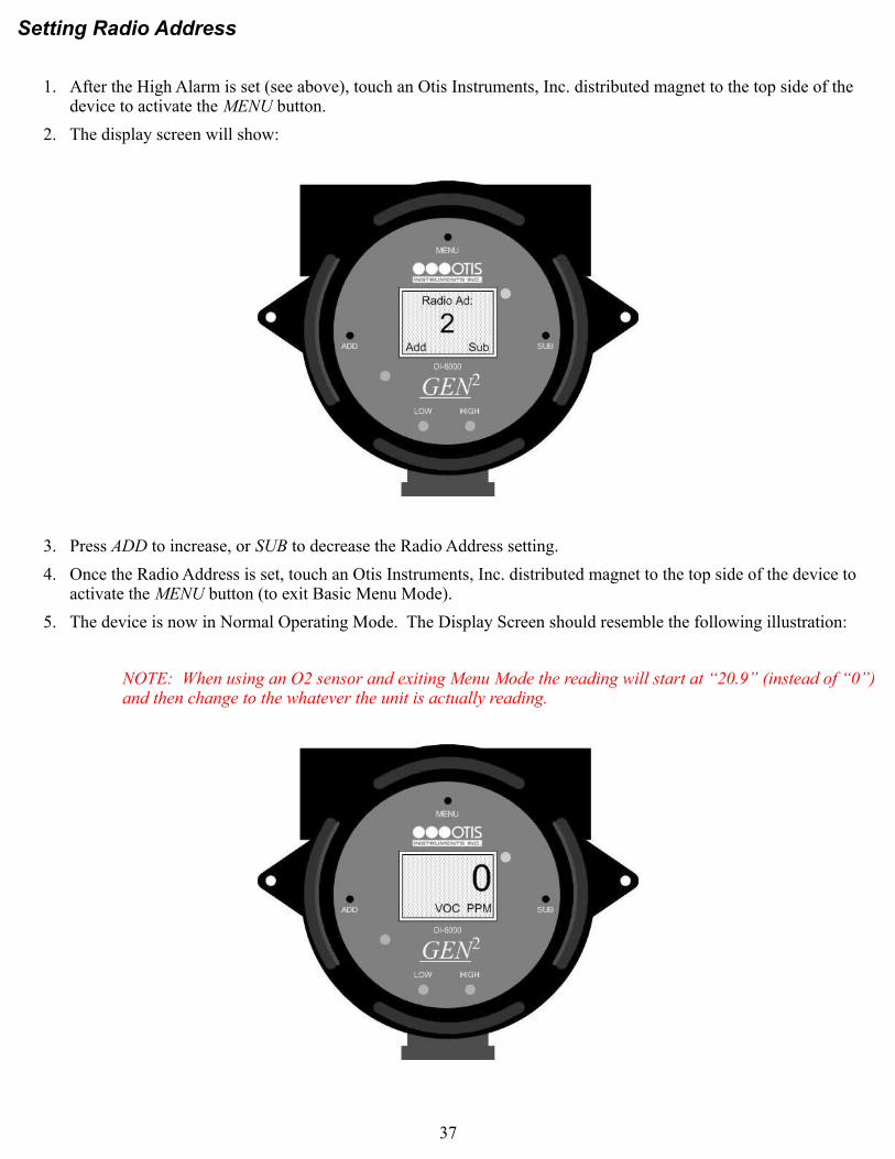
2. The display screen will show:
3. Press ADD to increase, or SUB to decrease the Radio Address setting.
4. Once the Radio Address is set, touch an Otis Instruments, Inc. distributed magnet to the top side of the device to activate the MENU button (to exit Basic Menu Mode).
5. The device is now in Normal Operating Mode. The Display Screen should resemble the following illustration:
NOTE: When using an O2 sensor and exiting Menu Mode the reading will start at “20.9” (instead of “0”) and then change to the whatever the unit is actually reading.
37

Advanced Menu ModeThe Advanced Menu Mode allows the user to: Test Relays/Alarms, set the Network ID, view Diagnostics, view Unit Info, Set Background, Set Relay 1 (Latching or Unlatching), Set Relay 2 (Latching or Unlatching), Set Modbus Address, Set Baud, Set 4-20mA Offset (Low), Set 4-20mA Offset (High), Set Contrast, and opt to (or not to) return the unit to Factory Default Settings.
Relays/Alarms Test Setting
The relays/alarms test should be completed periodically to ensure full functionality of the relays/alarms, and accurate transmission of radio waves from the device to the transmission controller.
1. While the device is in Normal Operating Mode, Touch and hold an Otis Instruments, Inc. distributed magnet against the top side of the device for approximately six seconds to active MENU and enter the Advanced Menu Mode.
2. The Display Screen will show:
38

Relays/Alarms Test Setting cont...
3. Touch the magnet to ADD to increase the reading by 5 PPM (or %). Continue touching the magnet to ADD until the increasing number reaches the pre-set level to trigger the relay/alarms.
4. Once the Relay/Alarm Test is complete (both LEDs and Alarms have been triggered), continue to the next step.
Setting Network ID
To ensure proper communication with the receiving monitor, set the Network ID to match the one assigned to the monitor.
NOTE: This setting only applies to sensor assemblies that contain a radio.
1. After the Relay/Alarms Test is complete (see above), touch an Otis Instruments, Inc. distributed magnet to the top side of the device to activate the MENU button.
2. The display screen will show:
39

Setting Network ID cont...
3. Touch the magnet to ADD (increase) or SUB (decrease) until the desired Network ID is displayed—this value will be a number from 1-78.
4. Once the Network ID is set, continue to the next step.
Diagnostics
The diagnostics screen allows the user to view the Radio, Scale, Battery Voltage (Power), and Sensor Voltage.
1. After the Network ID is set (see above), touch an Otis Instruments, Inc. distributed magnet to the top side of the device to activate the MENU button.
2. The display screen will show:
40
Diagnostics cont...
3. Once the Diagnostics have been viewed, continue to the next step.
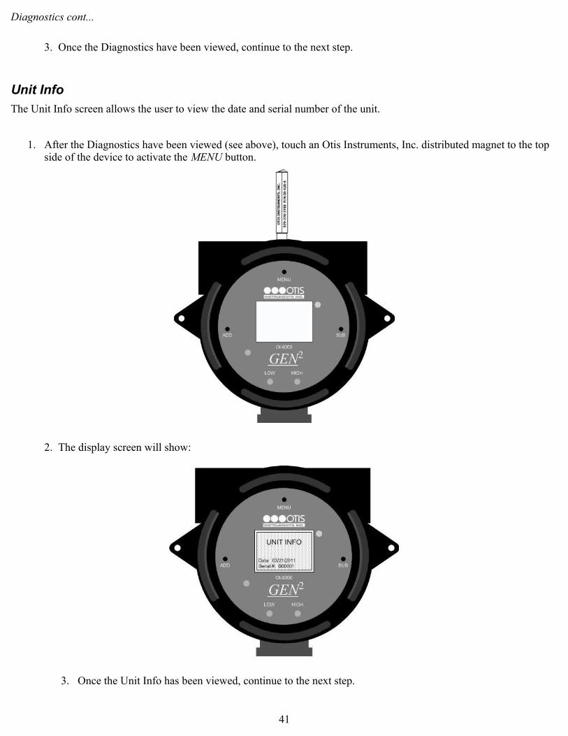
Unit Info
The Unit Info screen allows the user to view the date and serial number of the unit.
1. After the Diagnostics have been viewed (see above), touch an Otis Instruments, Inc. distributed magnet to the top side of the device to activate the MENU button.
2. The display screen will show:
3. Once the Unit Info has been viewed, continue to the next step.
41

Background Gas Setting
NOTE: When using an O2 sensor, two background setting modes will be available—Low and High. When in these modes, the Background Low will be called “BackgroundL”; the Background High will be called “BackgroundH”. When the background reading is below the Background Low setting—or above Background High setting—the unit will transmit every five seconds.
1. After the Unit Info has been viewed (see above), touch an Otis Instruments, Inc. distributed magnet to the top side of the device to activate the MENU button.
2. The display screen will show:
3. Touch the magnet to ADD (increase) or SUB (decrease) to adjust the Background Gas Setting.
NOTE: The maximum background level that can be set is 10% of full scale.
4. Once the Background Gas Setting has been set, continue to the next step.
42

Relay 1: Latching/Unlatching
1. After the Background Gas Setting has been set (see above), touch an Otis Instruments, Inc. distributed magnet to the top side of the device to activate the MENU button.
2. The display screen will show:
3. Touch the magnet to ADD or SUB to toggle between “Latch” and “UnLatch”.
4. Once the Relay 1: Latching/Unlatching has been set, continue to the next step.
43

Relay 2: Latching/Unlatching
1. After Relay 1: Latching/Unlatching has been set (see above), touch an Otis Instruments, Inc. distributed magnet to the top side of the device to activate the MENU button.
2. The display screen will show:
3. Touch the magnet to ADD or SUB to toggle between “Latch” and “UnLatch”.
4. Once the Relay 2: Latching/Unlatching has been set, continue to the next step.
44

Setting Modbus Address
1. After the Relay 2: Latching/Unlatching has been set (see above), touch an Otis Instruments, Inc. distributed magnet to the top side of the device to activate the MENU button.
2. The display screen will show:
3. Touch the magnet to ADD (increase) or SUB (decrease) until the desired Modbus Address is displayed (between 1-247).
4. Once the Modbus Address has been set, continue to the next step.
Setting Baud
1. After the Modbus Address has been set (see above), touch an Otis Instruments, Inc. distributed magnet to the top side of the device to activate the MENU button.
2. The display screen will show:
45
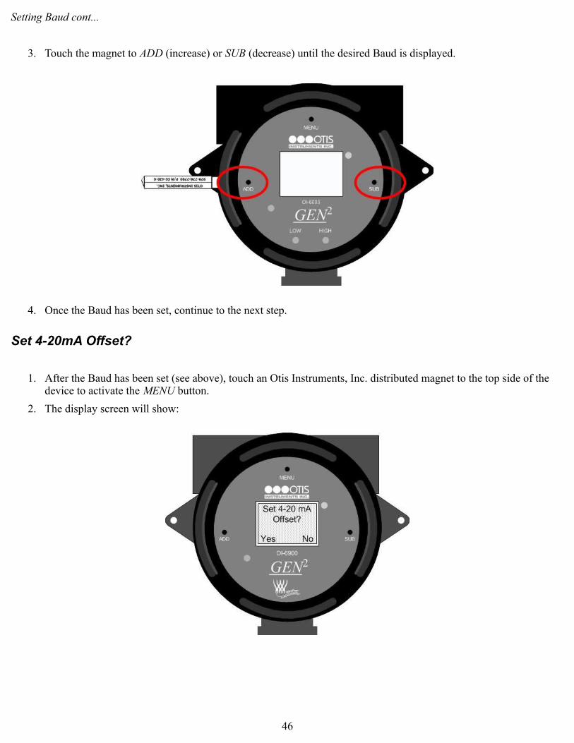
Setting Baud cont...
3. Touch the magnet to ADD (increase) or SUB (decrease) until the desired Baud is displayed.
4. Once the Baud has been set, continue to the next step.
Set 4-20mA Offset?
1. After the Baud has been set (see above), touch an Otis Instruments, Inc. distributed magnet to the top side of the device to activate the MENU button.
2. The display screen will show:
46

Set 4-20mA Offset? cont...
3. Touch the magnet to ADD for Yes, or SUB for no.
NOTE: If “Yes” is selected, proceed to the next step. If “No” is selected, continue to the step titled “Setting LCD Contrast”.
4. Once the 4-20mA Offset (Low) has been set, continue to the next step.
Set 4-20mA Offset (Low)
1. If “Yes” was chosen in the previous step, touch an Otis Instruments, Inc. distributed magnet to the top side of the device to activate the MENU button and the display screen will show:
NOTE: If there is a device connected to the 4-20mA output, proceed with calibration. If there is nothing connected to the 4-20mA output, proceed to the next step.
47

Set 4-20mA Offset (Low) cont...
3. While setting up the 4-20mA, the 4-20 will output a 4mA—this is the equivalent of a zero reading of PPM (or %). On the device connected to the 4-20, make sure it indicates the low end of the desired scale. Touch the magnet to ADD (increase) or SUB (decrease) until the correct value is displayed on the connected device.
4. Once the 4-20mA Offset (Low) has been set, continue to the next step.
Set 4-20mA Offset (High)
1. After the 4-20mA Offset (Low) has been set (see above), touch an Otis Instruments, Inc. distributed magnet to the top side of the device to activate the MENU
2. The display screen will show:
NOTE: If there is a device connected to the 4-20mA output, proceed with calibration. If there is nothing connected to the 4-20mA output, proceed to the next step.
48

Set 4-20mA Offset (High) cont...
3. While setting up the 4-20mA, the 4-20 will output a 20mA—this is the equivalent of a full scale reading of PPM (or %). On the device connected to the 4-20, make sure it indicates the high end of the desired scale. Touch the magnet to ADD (increase) or SUB (decrease) until the correct value is displayed on the connected controller.
4. Once the 4-20mA Offset (High) has been set, continue to the next step.
Setting LCD Contrast
1. After the 4-20mA has been set, or if “No” was selected for the option that allows the 4-20mA to be set (see above), touch an Otis Instruments, Inc. distributed magnet to the top side of the device to activate MENU.
2. The display screen will show:
3. Touch the magnet to ADD (increase) or SUB (decrease) until the contrast is at the desired setting.
4. Once the Contrast has been set, continue to the next step
49
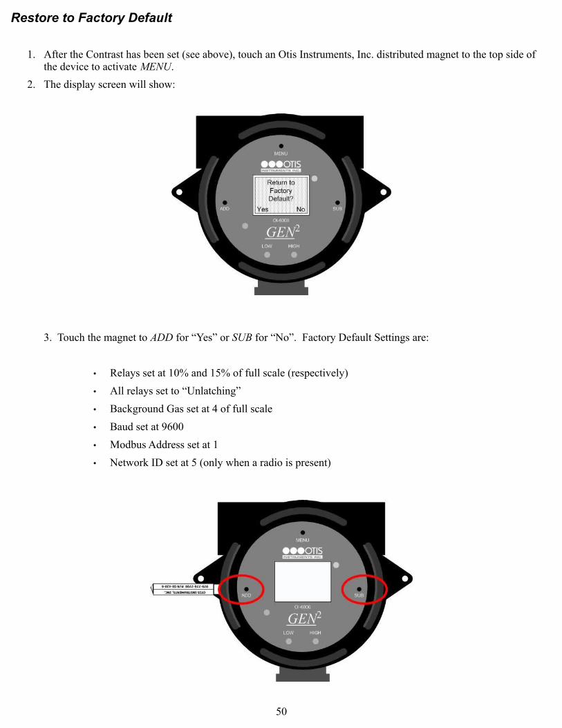
Restore to Factory Default
1. After the Contrast has been set (see above), touch an Otis Instruments, Inc. distributed magnet to the top side of the device to activate MENU.
2. The display screen will show:
3. Touch the magnet to ADD for “Yes” or SUB for “No”. Factory Default Settings are:
• Relays set at 10% and 15% of full scale (respectively)
• All relays set to “Unlatching”
• Background Gas set at 4 of full scale
• Baud set at 9600
• Modbus Address set at 1
• Network ID set at 5 (only when a radio is present)
50

Restore to Factory Default cont...
4. If “No” is selected, the device will return to Normal Operating Mode. If “Yes” is selected, the display screen will show:
5. Touch the magnet to ADD for “Yes” or SUB for “No”.
6. The device is now in Normal Operating Mode.
51

Antenna Replacement (WireFree Applications Only)The antenna is used to aid in sending clear and reliable radio signals to the transmission controller. If necessary, the current antenna can be replaced by an appropriate Otis Instruments, Inc. approved 2.4 GHz or 900 MHz antenna.
1. Power off the device by touching and holding an Otis Instruments, Inc. distributed magnet against the right side of the device for four to six seconds to activate SUB (which turns off device).
2. Locate the Antenna and Antenna Fitting.
3. Unscrew the current Antenna from the Antenna Fitting.
52

Antenna Replacement cont...
3. Screw the new Antenna onto the Antenna Fitting.
4. Power on the device by touching the magnet to ADD.
NOTE: When the magnet touches the device and a connection has been made a trapezoid will appear.
53

Appendix A: O2 Sensor Information
54

O2 Sensor Information
OI-6000 Sensor Assemblies for sensing O2 gas will perform differently than other OI-6000 Sensor Assemblies. The following items are variance that OI-6000 Sensor Assemblies for sensing O2 gas will have from other OI-6000 Sensor Assemblies.
Null
When Nulled, the reading will be 20.9.
Background Gas Setting
Two background setting modes will be available—Low and High. When in these modes, the Background Low will be called “BackgroundL”; the Background High will be called “BackgroundH”.
When the background reading is below the Background Low setting—or above Background High setting—the unit will transmit every five seconds.
Relay Settings
There will still be two available relays when using an O2 sensor, however: Relay 1 will trigger when the reading is below the Low Alarm Set Point; Relay 2 will trigger when the reading is above the High Alarm Set Point.
Exiting Menu Mode
When using an O2 sensor and exiting Menu Mode the reading will start at “20.9” (instead of “0”) and then change to the whatever the unit is actually reading.
Response Time
When sent out with a flame arrestor, the unit is slower to respond than GenI O2. This is because a different flame arrestor (than GenI) is being used.
O2 Percentile Range
The unit is designed for detecting O2 levels ranging from 10-25%.
55

Appendix B: OI-6000 Troubleshooting Guide
56
OI-6000 Troubleshooting Guide
• Fault 1
Indication: Sensor Timeout
Reason: OI-6000 digital sensor board problem
Solution: Check connections; replace sensor housing if still in Fault
Applies to: Setups that use a GenII sensor assembly
__________________________________________________________________________________________________
• Fault 4
Indication: ADC Not Responding
Reason: OI-6000, OI-6900 or OI-6975 analog sensor board not responding
Solution: Ensure that the analog board is properly connected; replace analog sensor board if still in Fault
Applies to: Setups that use a GenII sensor assembly
__________________________________________________________________________________________________
• Fault 14
Indication: Check Radio
Reason: No primary monitor
Solution: Ensure that a monitor is on. Ensure that the sensor assembly and monitor are set to the same radio address and Network ID.
Applies to: Setups that use a GenI and/or GenII sensor assemblies
57

Appendix C: Sensor Temperature Ranges
58
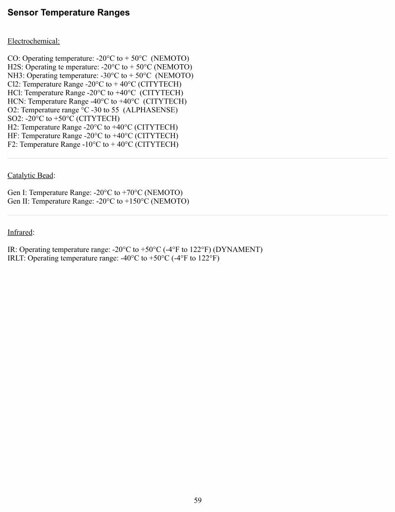
Sensor Temperature Ranges
Electrochemical:
CO: Operating temperature: -20°C to + 50°C (NEMOTO)H2S: Operating te mperature: -20°C to + 50°C (NEMOTO)NH3: Operating temperature: -30°C to + 50°C (NEMOTO)Cl2: Temperature Range -20°C to + 40°C (CITYTECH)HCl: Temperature Range -20°C to +40°C (CITYTECH)HCN: Temperature Range -40°C to +40°C (CITYTECH)O2: Temperature range °C -30 to 55 (ALPHASENSE)SO2: -20°C to +50°C (CITYTECH)H2: Temperature Range -20°C to +40°C (CITYTECH)HF: Temperature Range -20°C to +40°C (CITYTECH)F2: Temperature Range -10°C to + 40°C (CITYTECH)
Catalytic Bead:
Gen I: Temperature Range: -20°C to +70°C (NEMOTO)Gen II: Temperature Range: -20°C to +150°C (NEMOTO)
Infrared:
IR: Operating temperature range: -20°C to +50°C (-4°F to 122°F) (DYNAMENT)IRLT: Operating temperature range: -40°C to +50°C (-4°F to 122°F)
59

Appendix D: 4-20mA Current Loop Information
60

4-20mA Current Loop Introduction
This appendix in only an introduction. The information should serve as a brief overview of 4-20mA, and should not be considered a complete reference for proper implementation or use.
Prior knowledge of industry standards pertaining to 4-20mA specifically, and other aspects of electronics, are assumed to be known by the technician. For proper connection to a monitor or PLC, refer to the manufacturer's specific manual or instructions for that particular piece of hardware.
Overview
4-20mA ("four to twenty”), is an analog electrical transmission standard used by Otis Instruments for some of its ambient gas sensors and monitors. The signal is a current loop where 4mA represents zero percent signal, and 20mA represents 100 percent signal (full scale of the sensor assembly). The relationship between the current loop and the gas value is linear.
The 4mA allows the receiving monitor/PLC to distinguish between a zero signal, a broken wire, or a dead instrument. Benefits of 4-20mA convention are that it is: an industry standard, low-cost to implement, can reject some forms of electrical noise, and the signal does not change value around the “loop” (as apposed to a voltage). Only one current level can be present at any time; each device which operates via 4-20mA must to wired directly to the monitoring device.
Calculations
I 4−20= 16⋅value scale 4
I 4−20 : current of loop, measured in mA
value : PPM or %, of gas concentration
scale : full scale of sensor (see below for usual ranges)
Table – Gas Sensor Details
Actual ranges may vary with our product. If unsure, confirm with the actual gas sensor assembly distributor, Otis Instruments sales representative, or call the main Otis Instruments office for more details.
61
Target Gas Range Temp.H2S = Hydrogen Sulphide 0-100 ppm -20 to 50C
O2 = Oxygen 0-25 % -30 to 55CSO2 = Sulfur Dioxide 0-20 ppm -20 to 50CCL2 = Chlorine 0-10 ppm -20 to 50CH2 = Hydrogen 0-4 % -20 to 40C
NH3 = Ammonia 0-100 ppm -40 to 40CCO = Carbon Monoxide 0-999 ppm -20 to 50CF2 = Florine 0-1 ppm -10 to 40CHF = Hydrogen Fluoride 0-10 ppm -10 to 40C
H2S-2 = Hydrogen Sulphide 0-100 ppm -40 to 50C(extended temp)

Measuring Current
If the value measured is 0mA, then: the loop wires are broken, the sensor assembly is not powered up, the sensor assembly is malfunctioning, or the monitor is malfunctioning. A DMM (digital multi meter) or Current Meter may be used to test a 4-20mA signal. Place the DMM or Current Meter in line with the loop and measure current. The DMM/Current Meter may be used in conjunction with the normal monitoring device.
62

Specifications
Sensor Type: Catalytic Bead, Electro-Chemical, PID, or Infrared
Power: +12-35 Volts DC
Current Draw: 100 mA (max); actual draw depends on options & sensor type
Display: Graphical LCD (102x64), transflective, sunlight readable, LED backlight
Relays: Two Dry Contact (5 Amp) w/ 4 Amp Fuses
Protection: Power EMI filter, surge suppression, 4-20mA and RS-485 surge suppression
Output: 4-20mA (3-wire); RS-485 Modbus
Unit Radio Address: 1 to 255
Unit Modbus Address: 1-247
Radio Options: · 2.4 GHz ISM, 100mW· 900 MHz, 200mW
Interface: Three push buttons (MENU, ADD, SUB); three corresponding magnetic,
non-intrusive switches; non-intrusive calibration
Enclosure: Otis-Blue explosion/flame-proof
Certifications: CSA certified, Class 1, Div I, Groups C and D
Ex d IIB, Zone 1 Aex d IIb
Warranty: Hardware: One year (limited)
Sensor: One year (varies with sensor type)
63

Warranty Statement for WireFree Model OI-6000
Hardware
Otis Instruments, Inc. (Manufacturer) warrants its products to be free of defects in workmanship and materials—under normal use and service—from the date of purchase from the manufacturer or from the product's authorized reseller. The hardware for this device is under a one-year limited warranty.
The manufacturer is not liable (under this warranty) if its testing and examination disclose that the alleged defect in the product does not exist or was caused by the purchaser's (or any third party's) misuse, neglect, or improper installation, testing or calibrations. Any unauthorized attempt to repair or modify the product, or any other cause of damage beyond the range of the intended use, including damage by fire, lightening, water damage or other hazard, voids liability of the manufacturer.
In the event that a product should fail to perform up to manufacturer specifications during the applicable warranty period, contact the product's authorized reseller or return the product directly to the manufacturer with a Return Material Authorization (RMA). This number will be assigned upon contacting customer service at 979.776.7700 or [email protected]. The manufacturer will--at its option and expense--repair or replace the product, or deliver an equivalent product or part to the purchaser at no additional charge.
Any replaced or repaired product or part has either a 90-day warranty or the remainder of the initial warranty period (whichever is longer).
Sensor
The sensor contained in the device is covered under a one-year limited warranty (varies with sensor type).
64

Otis Instruments, Inc.
Corporate Office2200 E. Villa Maria Dr.
Bryan, TX 77802979.776.7700
www.otisinstruments.com
65