operation manual - otisinstruments.com · introduction this document is an operation manual...
TRANSCRIPT

Model OI-7010-X-X-X-3232-Channel Hybrid Monitor
_____________________________________________________Operation Manual
Revision 2.8w
_____________________________________________________________________________________

Product Overview
The Otis Instruments, Inc. Gen II OI-7010-X-X-X-32 is a Hybrid Monitor that supports up to 32 WireFree sensor assemblies, and up to four wired (4-20mA) sensors (when only 28 channels are setup as WireFree).
The OI-7010-X-X-X-32 is backward compatible with Gen I WireFree sensor assemblies, and also supports Gen II WireFree sensor assemblies (configurable).
For additional information regarding this OI-7010-X-X-X-32, see the Appendices at the end of this Operation Manual.
2
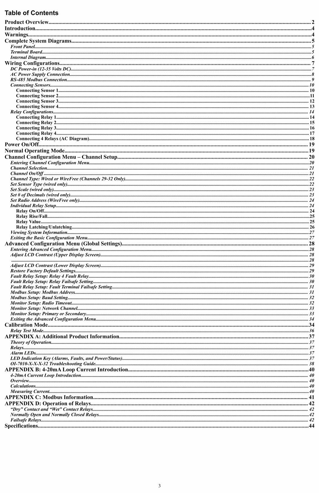
Table of ContentsProduct Overview.......................................................................................................................................................................................... 2Introduction....................................................................................................................................................................................................4Warnings.........................................................................................................................................................................................................4Complete System Diagrams..........................................................................................................................................................................5
Front Panel.....................................................................................................................................................................................................................................5Terminal Board...............................................................................................................................................................................................................................5Internal Diagram............................................................................................................................................................................................................................6
Wiring Configurations.................................................................................................................................................................................. 7DC Power-in (12-35 Volts DC).......................................................................................................................................................................................................7AC Power Supply Connection........................................................................................................................................................................................................8RS-485 Modbus Connection.......................................................................................................................................................................................................... 9Connecting Sensors......................................................................................................................................................................................................................10
Connecting Sensor 1............................................................................................................................................................................................................... 10Connecting Sensor 2................................................................................................................................................................................................................11Connecting Sensor 3............................................................................................................................................................................................................... 12Connecting Sensor 4............................................................................................................................................................................................................... 13
Relay Configurations................................................................................................................................................................................................................... 14Connecting Relay 1................................................................................................................................................................................................................. 14Connecting Relay 2................................................................................................................................................................................................................. 15Connecting Relay 3................................................................................................................................................................................................................. 16Connecting Relay 4................................................................................................................................................................................................................. 17Connecting 4 Relays (AC Diagram)...................................................................................................................................................................................... 18
Power On/Off............................................................................................................................................................................................... 19Normal Operating Mode.............................................................................................................................................................................19Channel Configuration Menu – Channel Setup....................................................................................................................................... 20
Entering Channel Configuration Menu......................................................................................................................................................................................20Channel Selection........................................................................................................................................................................................................................ 21Channel On/Off ...........................................................................................................................................................................................................................21Channel Type: Wired or WireFree (Channels 29-32 Only)........................................................................................................................................................22Set Sensor Type (wired only)........................................................................................................................................................................................................22Set Scale (wired only)...................................................................................................................................................................................................................23Set # of Decimals (wired only)..................................................................................................................................................................................................... 23Set Radio Address (WireFree only)............................................................................................................................................................................................. 24Individual Relay Setup................................................................................................................................................................................................................. 24
Relay On/Off........................................................................................................................................................................................................................... 24Relay Rise/Fall.........................................................................................................................................................................................................................25Relay Value.............................................................................................................................................................................................................................. 25Relay Latching/Unlatching.................................................................................................................................................................................................... 26
Viewing System Information........................................................................................................................................................................................................27Exiting the Basic Configuration Menu....................................................................................................................................................................................... 27
Advanced Configuration Menu (Global Settings).................................................................................................................................... 28Entering Advanced Configuration Menu....................................................................................................................................................................................28Adjust LCD Contrast (Upper Display Screen)............................................................................................................................................................................ 28 ......................................................................................................................................................................................................................................................28Adjust LCD Contrast (Lower Display Screen)............................................................................................................................................................................ 29Restore Factory Default Settings.................................................................................................................................................................................................29Fault Relay Setup: Relay 4 Fault Relay......................................................................................................................................................................................30Fault Relay Setup: Relay Failsafe Setting.................................................................................................................................................................................. 30Fault Relay Setup: Fault Terminal Failsafe Setting.................................................................................................................................................................. 31Modbus Setup: Modbus Address................................................................................................................................................................................................. 31Modbus Setup: Baud Setting....................................................................................................................................................................................................... 32Monitor Setup: Radio Timeout.................................................................................................................................................................................................... 32Monitor Setup: Network Channel............................................................................................................................................................................................... 33Monitor Setup: Primary or Secondary........................................................................................................................................................................................ 33Exiting the Advanced Configuration Menu................................................................................................................................................................................ 34
Calibration Mode.........................................................................................................................................................................................34Relay Test Mode............................................................................................................................................................................................................................36
APPENDIX A: Additional Product Information...................................................................................................................................... 37Theory of Operation..................................................................................................................................................................................................................... 37Relays............................................................................................................................................................................................................................................37Alarm LEDs..................................................................................................................................................................................................................................37LED Indication Key (Alarms, Faults, and Power/Status).......................................................................................................................................................... 37OI-7010-X-X-X-32 Troubleshooting Guide................................................................................................................................................................................ 38
APPENDIX B: 4-20mA Loop Current Introduction................................................................................................................................404-20mA Current Loop Introduction............................................................................................................................................................................................ 40Overview....................................................................................................................................................................................................................................... 40Calculations..................................................................................................................................................................................................................................40Measuring Current.......................................................................................................................................................................................................................40
APPENDIX C: Modbus Information........................................................................................................................................................ 41APPENDIX D: Operation of Relays.......................................................................................................................................................... 42
“Dry” Contact and “Wet” Contact Relays.................................................................................................................................................................................. 42Normally Open and Normally Closed Relays..............................................................................................................................................................................42Failsafe Relays............................................................................................................................................................................................................................. 42
Specifications................................................................................................................................................................................................44
3

Introduction
This document is an Operation Manual containing diagrams and step-by-step instruction for proper operation of the Otis Instruments, Inc. Gen II OI-7010-X-X-X-32. This document should be read before initial operation of the product.
Should a question arise during the use of the product, this document will serve as a first reference for consultation. If further questions arise, or if the device is not working properly, please contact the sales representative of this product.
Warnings
Even when the Power switch is in the off position, the AC and DC terminals are still hot—regardless of if the device is wired as DC.
CAUTION: THE INTERNAL COMPONENTS CAN BE STATIC SENSITIVE. USE CAUTION WHEN OPENING THE ENCLOSURE AND HANDLING INTERNAL COMPONENTS.
4

Complete System Diagrams
The following diagrams should be consulted for identification of Panels, Boards, and any other system part that may be referred to in this Operation Manual.
Front Panel
Terminal Board
5

Internal Diagram
6

Wiring Configurations
The following Wiring Configurations must be completed before initial operation of the product.
CAUTION: THE INTERNAL COMPONENTS CAN BE STATIC SENSITIVE. USE CAUTION WHEN OPENING THE ENCLOSURE AND HANDLING INTERNAL COMPONENTS.
▪
DC Power-in (12-35 Volts DC)
NOTE: The unit will be wired for the power-type that is requested by the purchaser when shipped from Otis Instruments..
● Provide a clean and stable 12-35 Volts DC voltage. Failure to to do so may cause the unit (and any wired sensors that are connected to the unit) to not operate properly.
● Voltage spikes higher than 35 Volts may damage the unit.
● Solar Panel power (with battery backup): This options may be used to power the unit, however, care must be taken to ensure the proper voltage and wattage is used.
NOTE: The size that the solar panel should be (10, 30, 50, or 100 watts, for example) depends on several factors, including: geographical area, line-of-sight access to the sun, number of wired sensors connected, and weather conditions.
Please consult a solar panel manufacture for specific details. Otis Instruments may also be contacted to provide guidance and recommendations.
1. Open the enclosure box to expose the Front Panel.
2. Unscrew the two thumb screws on the Front Panel.
3. Open the Front Panel so that the Terminal Board is exposed (reverse of Front Panel).
4. Locate the Power Terminal (on the lower right side of the Back Panel) and connect the DC-live wire (red) to the terminal marked “+12-35 VDC”.
5. Connect the DC-ground wire (black) to the terminal marked “GND”.
6. If desired, connect an Earth Ground wire (green) to the terminal marked “EGND” (required for surge suppression).
7. Close the Front Panel.
8. Screw in the thumb-screws.
9. Close the enclosure box.
10.Clamp down the enclosure latches.
7

AC Power Supply Connection
For AC Power applications, the Delta Power Supply (located inside the enclosure box) should be used.
NOTE: The unit will be wired for the power-type that is requested by the purchaser when shipped from Otis Instruments.
1. Open the enclosure box to expose the Front Panel.
2. Unscrew the two thumb-screws on the Front Panel.
3. Open the Front Panel so that the AC (Delta) Power Supply is exposed.
4. Connect a positive (red) wire to the Power Terminal terminal labeled “+12-35 VDC” on the Terminal Board.
5. Connect the other end of that same positive (red) wire from the Terminal Board to the terminal labeled “+V” on the Delta power supply.
6. Connect a negative (black) wire from the Power Terminal terminal labeled “GND” on the Terminal Board.
7. Connect the other end of that same negative (black) wire from the Terminal Board to the terminal labeled “-V” on the Delta power supply.
8. There will be three wires (black, white and green) pre-wired from the Delta power supply terminals “L” (AC Load IN), “N” (AC Neutral IN), and “EG” (Chassis GND or Earth GND). This set of wires will be used to plug into an AC power outlet ONCE ALL WIRING CONFIGURATIONS ARE COMPLETE.
9. Close the Front Panel.
10.Screw in the thumb-screws.
11.Close the enclosure box.
12.Clamp down the enclosure latches.
8
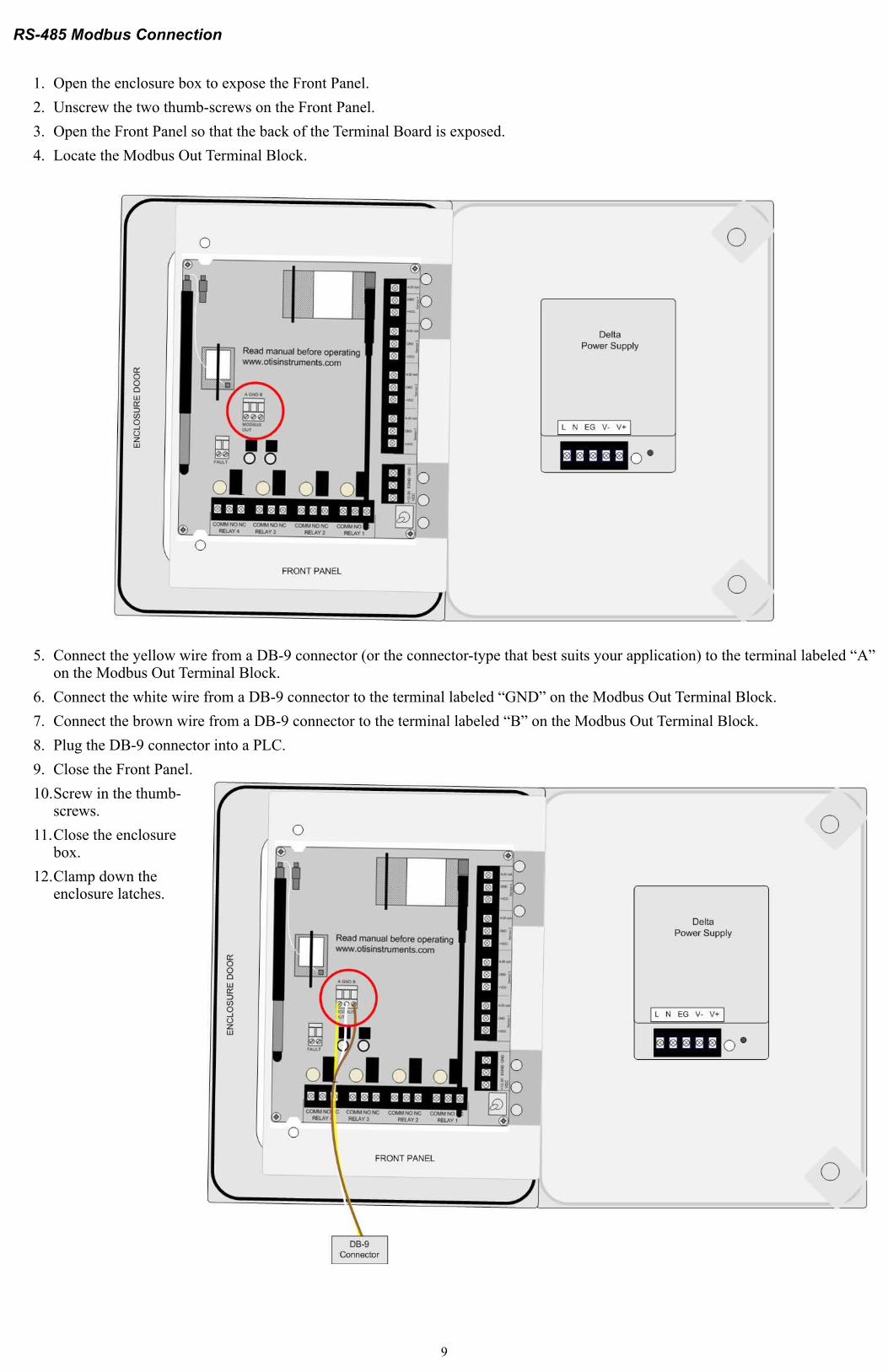
RS-485 Modbus Connection
1. Open the enclosure box to expose the Front Panel.
2. Unscrew the two thumb-screws on the Front Panel.
3. Open the Front Panel so that the back of the Terminal Board is exposed.
4. Locate the Modbus Out Terminal Block.
5. Connect the yellow wire from a DB-9 connector (or the connector-type that best suits your application) to the terminal labeled “A” on the Modbus Out Terminal Block.
6. Connect the white wire from a DB-9 connector to the terminal labeled “GND” on the Modbus Out Terminal Block.
7. Connect the brown wire from a DB-9 connector to the terminal labeled “B” on the Modbus Out Terminal Block.
8. Plug the DB-9 connector into a PLC.
9. Close the Front Panel.
10.Screw in the thumb-screws.
11.Close the enclosure box.
12.Clamp down the enclosure latches.
9
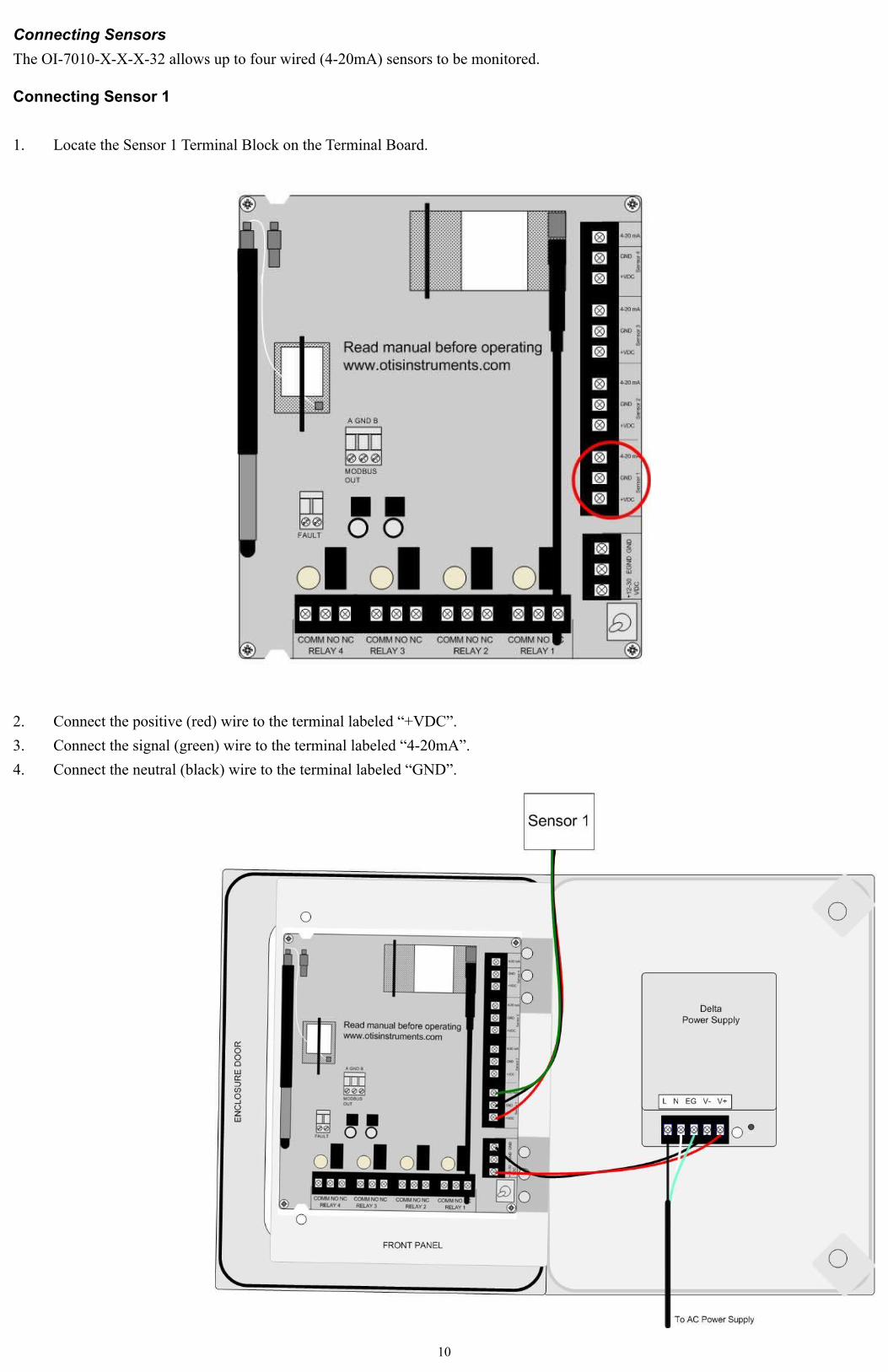
Connecting Sensors
The OI-7010-X-X-X-32 allows up to four wired (4-20mA) sensors to be monitored.
Connecting Sensor 1
1. Locate the Sensor 1 Terminal Block on the Terminal Board.
2. Connect the positive (red) wire to the terminal labeled “+VDC”.
3. Connect the signal (green) wire to the terminal labeled “4-20mA”.
4. Connect the neutral (black) wire to the terminal labeled “GND”.
10

Connecting Sensor 2
1. Locate the Sensor 2 Terminal Block on the Terminal Board.
2. Connect the positive (red) wire to the terminal labeled “+VDC”.
3. Connect the signal (green) wire to the terminal labeled “4-20mA”.
4. Connect the neutral (black) wire to the terminal labeled “GND”.
11
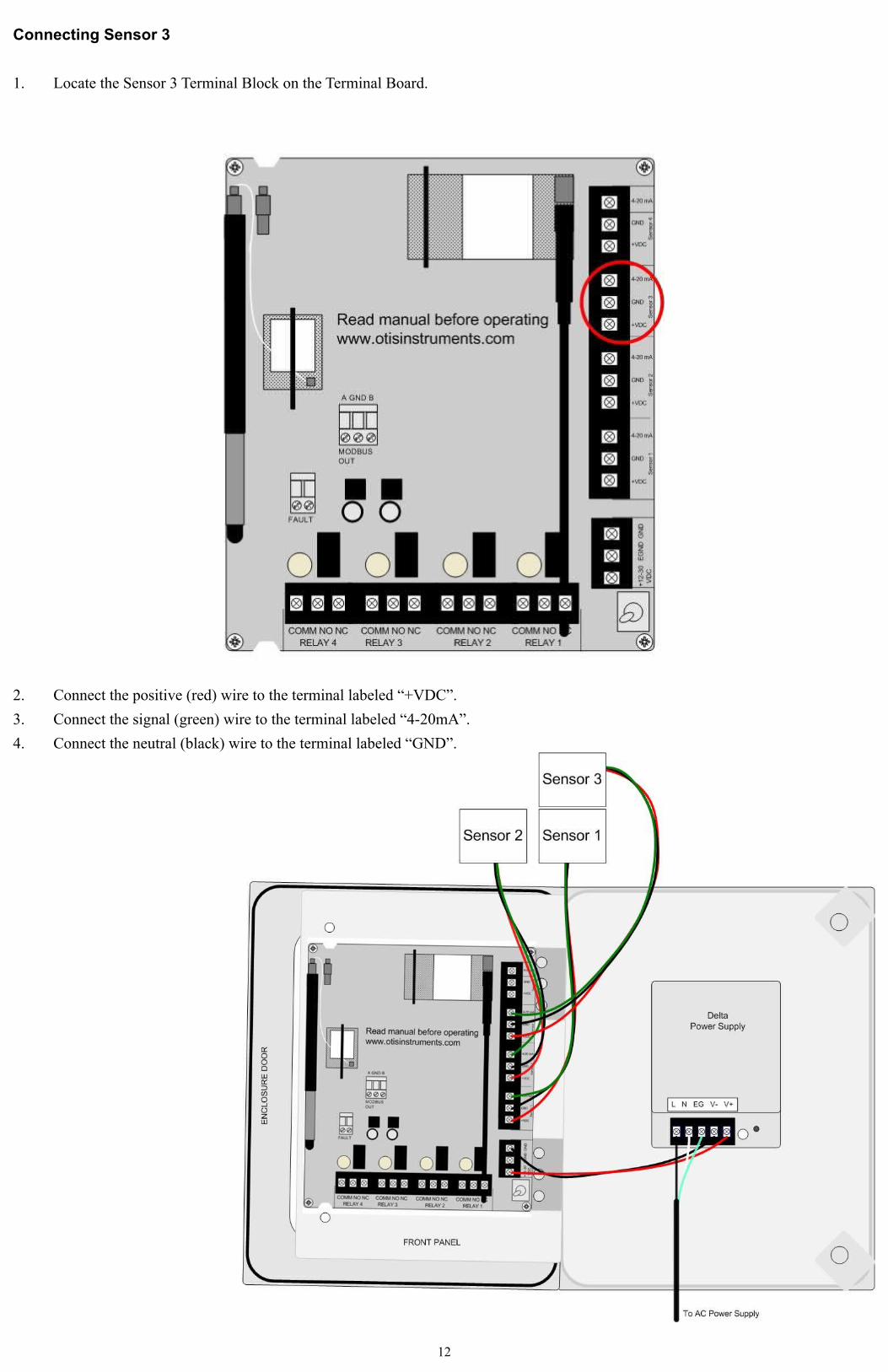
Connecting Sensor 3
1. Locate the Sensor 3 Terminal Block on the Terminal Board.
2. Connect the positive (red) wire to the terminal labeled “+VDC”.
3. Connect the signal (green) wire to the terminal labeled “4-20mA”.
4. Connect the neutral (black) wire to the terminal labeled “GND”.
12

Connecting Sensor 4
1. Locate the Sensor 4 Terminal Block on the Terminal Board.
2. Connect the positive (red) wire to the terminal labeled “+VDC”.
3. Connect the signal (green) wire to the terminal labeled “4-20mA”.
4. Connect the neutral (black) wire to the terminal labeled “GND”.
13

Relay Configurations
The OI-7010-X-X-X-32 offers four relays to be setup. Each of the four relays may be setup as Normally Open (NO) or Normally Closed (NC).
Connecting Relay 1
1. Locate the Relay 1 Terminal Block on the Terminal Board.
2. Connect the live wire (red) from the Relay 1 Alarm (light/horn) to the terminal labeled “NO” (or “NC”) on the Relay 1 Terminal Block.
3. Connect the neutral wire (black) from the Relay 1 Alarm (light/horn) to the terminal labeled “GND” on the DC Power Supply Terminal Block.
4. Connect the jumper wire (blue) from the terminal labeled “+12-35 VDC” on the DC Power Supply Terminal Block to the terminal labeled “COM” on the Relay 1 Terminal Block.
14

Connecting Relay 2
1. Locate the Relay 2 Terminal Block on the Terminal Board.
2. Connect the live wire (red) from the Relay 2 Alarm (light/horn) to the terminal labeled “NO” (or “NC”) on the Relay 2 Terminal Block.
3. Connect the neutral wire (black) from the Relay 2 Alarm (light/horn) to the terminal labeled “GND” on the DC Power Supply Terminal Block.
4. Connect a jumper wire (blue) from the terminal labeled “COM” on the Relay 1 terminal block to the terminal labeled “COM” on the Relay 2 terminal block.
15

Connecting Relay 3
1. Locate the Relay 3 Terminal Block on the Terminal Board.
2. Connect the live wire (red) from the Relay 3 Alarm (light/horn) to the terminal labeled “NO” (or “NC”) on the Relay 3 Terminal Block.
3. Connect the neutral wire (black) from the Relay 3 Alarm (light/horn) to the terminal labeled “GND” on the DC Power Supply Terminal Block.
4. Connect a jumper wire (blue) from the terminal labeled “COM” on the Relay 2 terminal block to the terminal labeled “COM” on the Relay 3 terminal block.
16

Connecting Relay 4
1. Locate the Relay 4 Terminal Block on the Terminal Board.
2. Connect the live wire (red) from the Relay 4 Alarm (light/horn) to the terminal labeled “NO” (or “NC”) on the Relay 4 Terminal Block.
3. Connect the neutral wire (black) from the Relay 4 Alarm (light/horn) to the terminal labeled “GND” on the DC Power Supply Terminal Block.
4. Connect a jumper wire (blue) from the terminal labeled “COM” on the Relay 3 terminal block to the terminal labeled “COM” on the Relay 4 terminal block.
17

Connecting 4 Relays (AC Diagram)
18

Power On/Off
Powering on the device activates its functions. When powered on, the device is fully functional and access to system and settings menus is allowed.
Once power is supplied to the OI-7010-X-X-X-32—by being plugged into an AC outlet or by being wired to a DC power supply—the display screens and LEDs will illuminate.
To cycle the Terminal Board power, flip the Power Switch (located on the lower right side of the Terminal Board) to the OFF (and then ON) position.
Normal Operating Mode
The OI-7010-X-X-X-32 can receive a total of 32 sensor assemblies: up to 32 WireFree sensor assemblies and up to four wired (4-20mA) sensor assemblies. When in Normal Operating Mode, configured channels are scanned through every three seconds. When in Normal Operating Mode, the following items are displayed for each channel—two channels at a time, one channel per display screen:
▪ Channel
▪ Address
▪ Gas Reading
▪ Time Since Last Transmission
▪ Battery Voltage of the Displayed Sensor Assembly
▪ Fault (if any)
The following illustration shows the OI-7010-X-X-X-32 in Normal Operating Mode. In this illustration, sensor assembly 1 is in Fault, sensor assembly 2 is not in Fault.
19

Channel Configuration Menu – Channel Setup
The Channel Configuration Menu is used to setup individual channels (per sensor).
Entering Channel Configuration Menu
1. Open the enclosure box to expose the Front Panel. The display screens will resemble the following illustration:
2. Press and hold MENU, ADD and SUB for five seconds.
3. Once in the Channel Configuration Menu, complete the next steps in this section. The user must complete the following tasks for EACH sensor (up to 32 WireFree; the last four channels (29-32) may be setup for wired sensors).
NOTE: Only one channel may be setup at a time; to setup additional channels, repeat the process (in its entirety) for each additional channel, or use the “Duplicate Settings” feature as explained in this section of the Operation Manual..
20

Channel Selection
1. Press ADD (increase) or SUB (decrease) to choose the channel to configured.
2. When the desired channel is displayed, press MENU (next) to continue to the next menu option.
Channel On/Off
1. Press ADD or SUB to manipulate the channel's On/Off status.
2. Press MENU (next) to continue to the next menu option.
21

Channel Type: Wired or WireFree (Channels 29-32 Only)
NOTE: For WireFree settings, skip to page 24.
1. Press ADD or SUB to manipulate the channel type as “Wired (4-20mA)” or “WireFree”.
2. Press MENU (next) to continue to the next menu option.
Set Sensor Type (wired only)
1. Press ADD or SUB to specify what the sensor will see. Options include: H2S, SO2, O2, CO, Cl2, CO2, LEL, VOC, FEET, HCl, NH3, H2, or None.
2. Press MENU (next) to continue to the next menu option.
22

Set Scale (wired only)
1. Press ADD (increase) or SUB (decrease) to manipulate the wired sensor's scale (1-65,000).
2. Press MENU (next) to continue to the next menu option.
Set # of Decimals (wired only)
1. Press ADD (increase) or SUB (decrease) to manipulate the display screen's number of decimals. The number of decimals available to be set will depend on the previously set scale.
▪ 3 decimals: Scale 1 or less
▪ 2 decimals: Scale 10 or less
▪ 1 decimal: Scale 100 or less
▪ 0 decimal: Scale greater than 100 (the Set # of Decimals option will not show up in this case)
2. Press MENU (next) to continue to the next menu option, then skip to the next section.
23

Set Radio Address (WireFree only)
1. Press ADD (increase) or SUB (decrease) to manipulate the Radio Address (1-255).
2. Press MENU (next) to continue to the next menu option.
Individual Relay Setup
NOTE: Repeat the Individual Relay Setup process for each relay—and each channel—to be setup.
Relay On/Off
1. Press ADD or SUB to manipulate the relay's On/Off status.
2. Press MENU (next) to continue to the next menu option.
24

Relay Rise/Fall
1. Press ADD or SUB to manipulate the relay's Rise/Fall status.
2. Press MENU (next) to continue to the next menu option.
Relay Value
1. Press ADD (increase) or SUB (decrease) to manipulate the relay threshold value (1-65,000).
2. Press MENU (next) to continue to the next menu option.
25

Relay Latching/Unlatching
1. Press ADD or SUB to manipulate the relay's Latching/Unlatching status.
2. Press MENU (next) to continue to the next option—setting up the next consecutive relay.
Once all four relays have been setup, the display screen will show the following:
3. Press MENU (Next) to setup the next channel; Press ADD (Yes) to duplicate the settings to all consecutive channels; or, Continue to the next section for “Exiting the Basic Configuration Menu” instructions.
26

Viewing System Information
After the 12th channel is set, press MENU to view the system's information, including the:
▪ Build-date
▪ Serial number
▪ Radio (type)
▪ Radio error
Exiting the Basic Configuration Menu
Complete the following steps to exit the Basic Configuration Menu at any time.
1. Press ESC to exit the Basic Configuration Menu.
NOTE: After the 12th (or 32nd) channel is set—and if MENU is pressed instead of ESC—there is an information-update on the display screen indicating the build-date, serial number, radio (type), and radio error of the OI-7010-X-X-X-32.
2. Close the enclosure box.
3. Screw in the thumb-screws.
4. Clamp down the enclosure latches.
NOTE: The monitor will automatically exit Chanel Setup after 15 minutes.
CHANNEL SETUP MUST BE COMPLETED
INDIVIDUALLY FOR EACH CHANNEL.
REPEAT THE CHANNEL SETUP
INSTRUCTIONS FOR EACH CHANNEL.
27

Advanced Configuration Menu (Global Settings)
The Advanced Configuration Menu is used to manipulate global settings. To setup individual channels, use the Channel Configuration Menu.
Entering Advanced Configuration Menu
1. Open the enclosure box to expose the Front Panel.
2. Cycle the unit's power (turn the Terminal Board Power Switch OFF, then ON). For more detailed instructions regarding how to cycle the unit's power, refer to the “Power On/Off” section of this Operation Manual.
3. When the Display Screens illuminate, press MENU.
NOTE: Do not wait for the countdown to finish.
Adjust LCD Contrast (Upper Display Screen)
1. Press ADD (increase) or SUB (decrease) to manipulate the LCD contrast of the Upper Display Screen.
2. Press MENU (Next) to continue to the next Advanced Configuration Menu option.
28
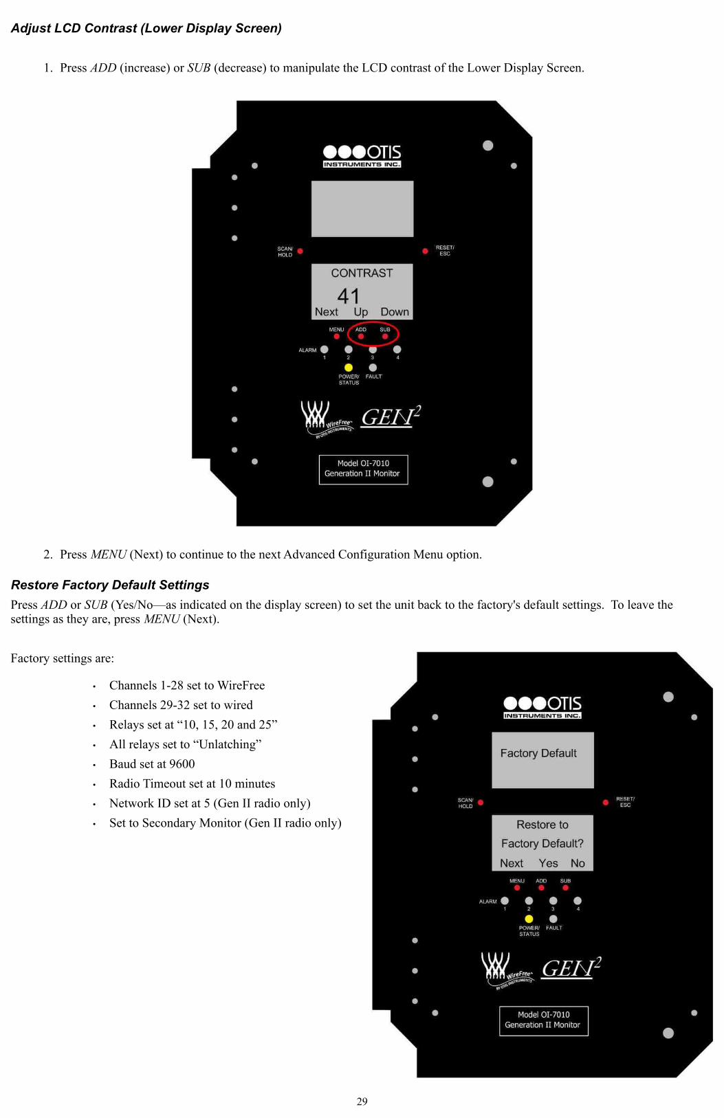
Adjust LCD Contrast (Lower Display Screen)
1. Press ADD (increase) or SUB (decrease) to manipulate the LCD contrast of the Lower Display Screen.
2. Press MENU (Next) to continue to the next Advanced Configuration Menu option.
Restore Factory Default Settings
Press ADD or SUB (Yes/No—as indicated on the display screen) to set the unit back to the factory's default settings. To leave the settings as they are, press MENU (Next).
Factory settings are:
• Channels 1-28 set to WireFree
• Channels 29-32 set to wired
• Relays set at “10, 15, 20 and 25”
• All relays set to “Unlatching”
• Baud set at 9600
• Radio Timeout set at 10 minutes
• Network ID set at 5 (Gen II radio only)
• Set to Secondary Monitor (Gen II radio only)
29
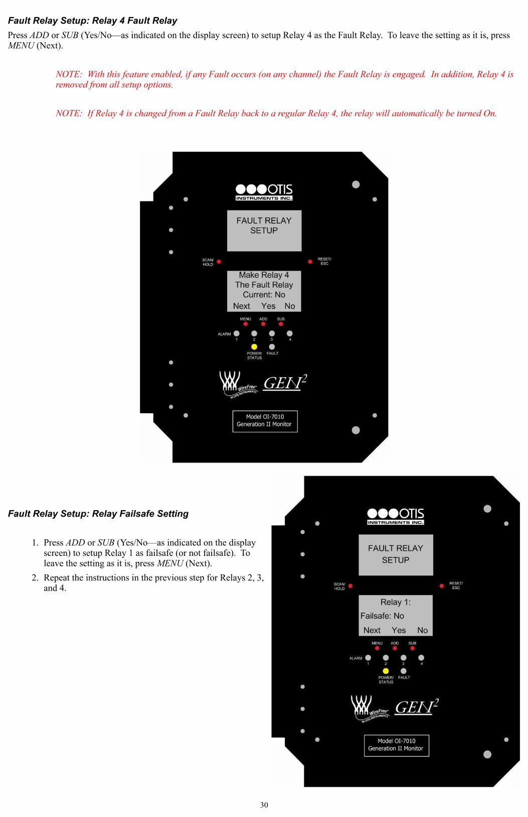
Fault Relay Setup: Relay 4 Fault Relay
Press ADD or SUB (Yes/No—as indicated on the display screen) to setup Relay 4 as the Fault Relay. To leave the setting as it is, press MENU (Next).
NOTE: With this feature enabled, if any Fault occurs (on any channel) the Fault Relay is engaged. In addition, Relay 4 is removed from all setup options.
NOTE: If Relay 4 is changed from a Fault Relay back to a regular Relay 4, the relay will automatically be turned On.
Fault Relay Setup: Relay Failsafe Setting
1. Press ADD or SUB (Yes/No—as indicated on the display screen) to setup Relay 1 as failsafe (or not failsafe). To leave the setting as it is, press MENU (Next).
2. Repeat the instructions in the previous step for Relays 2, 3, and 4.
30
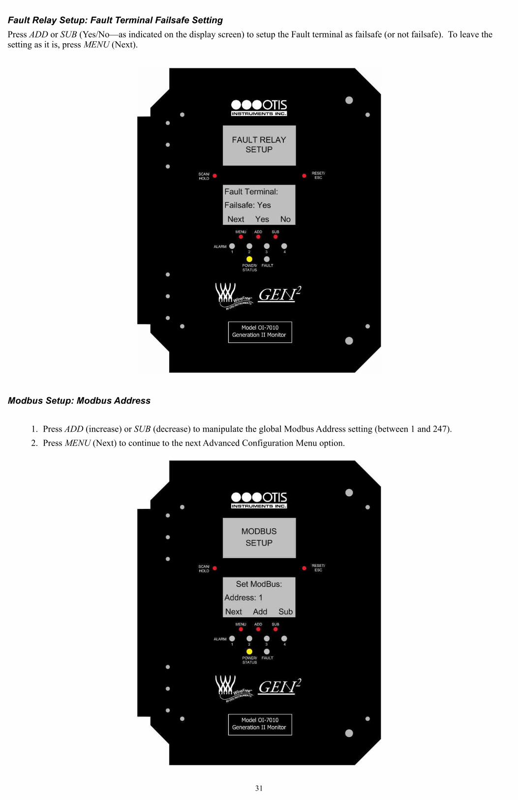
Fault Relay Setup: Fault Terminal Failsafe Setting
Press ADD or SUB (Yes/No—as indicated on the display screen) to setup the Fault terminal as failsafe (or not failsafe). To leave the setting as it is, press MENU (Next).
Modbus Setup: Modbus Address
1. Press ADD (increase) or SUB (decrease) to manipulate the global Modbus Address setting (between 1 and 247).
2. Press MENU (Next) to continue to the next Advanced Configuration Menu option.
31
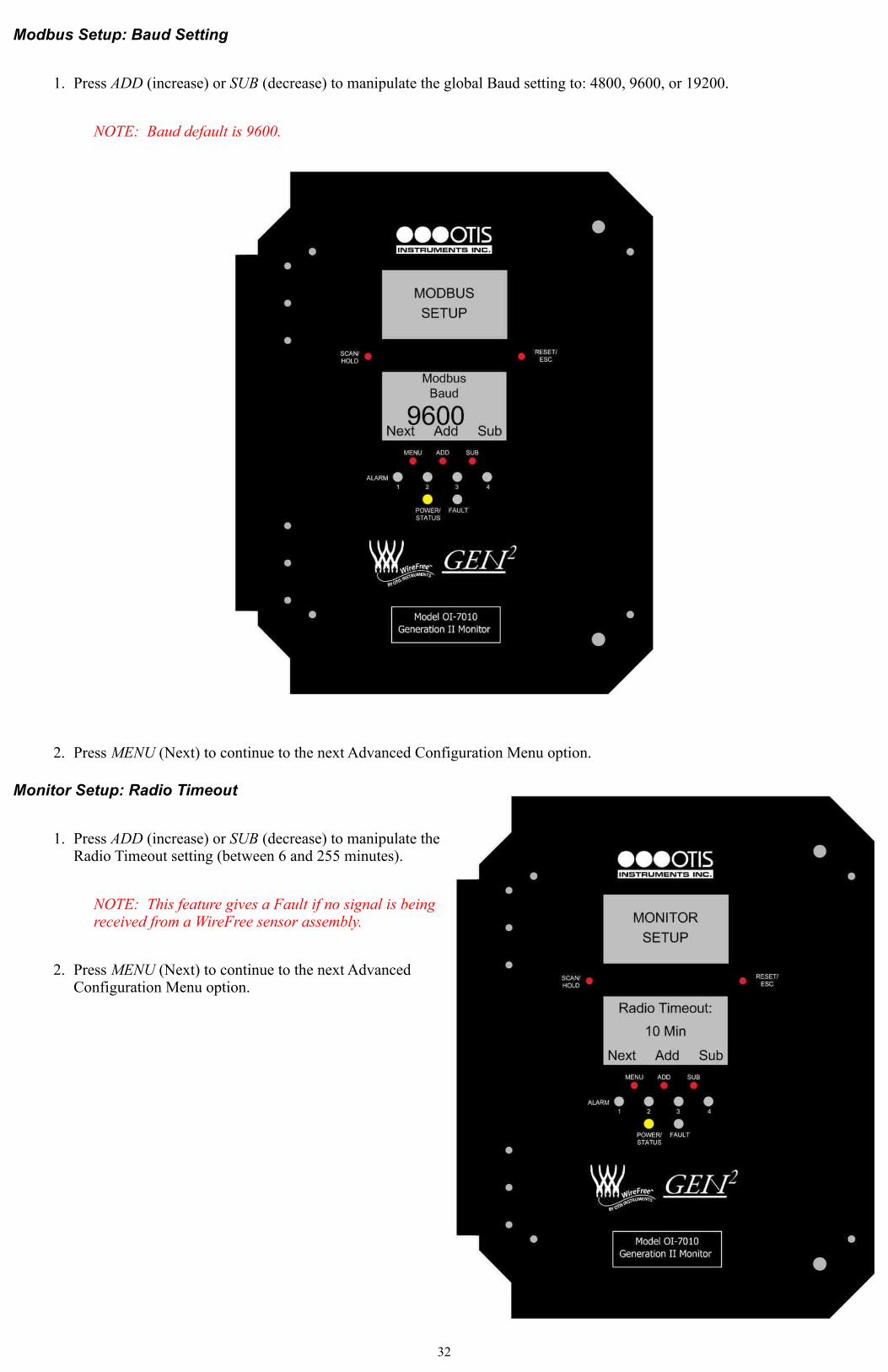
Modbus Setup: Baud Setting
1. Press ADD (increase) or SUB (decrease) to manipulate the global Baud setting to: 4800, 9600, or 19200.
NOTE: Baud default is 9600.
2. Press MENU (Next) to continue to the next Advanced Configuration Menu option.
Monitor Setup: Radio Timeout
1. Press ADD (increase) or SUB (decrease) to manipulate the Radio Timeout setting (between 6 and 255 minutes).
NOTE: This feature gives a Fault if no signal is being received from a WireFree sensor assembly.
2. Press MENU (Next) to continue to the next Advanced Configuration Menu option.
32

Monitor Setup: Network Channel
1. Press ADD (increase) or SUB (decrease) to manipulate the Gen II Network Channel setting (between 1 and 78).
NOTE: This feature only shows up if the monitor contains a Gen II radio. All monitors and sensors on a Gen II network MUST have the same Network Channel in order to communicate.
1. l2. Press MENU (Next) to continue to the next Advanced Configuration Menu option.
Monitor Setup: Primary or Secondary
1. Press ADD or SUB to switch the monitor setting to “Primary” or “Secondary”.
NOTE: This setting will only appear if your monitor contains a Gen II radio. Setting the monitor to “Primary” or “Secondary” is only necessary when using a Gen II radio. On each Gen II network there can be only one “Primary” monitor—all other monitors must be setup as “Secondary” monitors.
NOTE: If a OI-7010-X-X-X-32 with a Gen II radio is set as a “Secondary” monitor when there is no “Primary” monitor, the OI-7010-X-X-X-32 will go into Fault 15 and the Power/Status LED will be green if the monitor becomes the “Primary” monitor; otherwise, the Power/Status LED will be blue.
2. Press MENU (Next) to exit the Advanced Configuration Menu and return to Normal Operating Mode.
33

Exiting the Advanced Configuration Menu
Complete the following steps to exit the Advanced Configuration Menu at any time.
1. Press ESC to exit the Advanced Configuration Menu.
2. Close the enclosure box.
3. Clamp down the enclosure latches.
Calibration Mode
Entering Calibration Mode disables the relays and allows the sensors to be calibrated without triggering alarms. Once in Calibration Mode, the unit will remain in this state for two hours—unless RESET/ESC is pressed.
1. Open the enclosure box to expose the Front Panel.
2. To enter Calibration Mode, press and hold MENU for five seconds.
34

Calibration Mode cont...
3. Once in Calibration Mode, the display screen will show “CAL” on the upper right side.
The illustration below shows what the display screens will show if no sensor is detected for a channel while in Calibration Mode. In this illustration, there is no sensor detected for a wired channel (Channel 9), as well as no sensor detected for a WireFree channel (Channel 10) while in Calibration Mode.
4. To return to Normal Operating Mode, press RESET/ESC.
5. Close the enclosure box.
6. Clamp down the enclosure latches.
35

Relay Test Mode
Relay Test Mode activates each relay, and can be used to determine whether or not the relays and attached alarms are functioning properly.
1. Open the enclosure box to expose the Front Panel.
2. To enter Relay Test Mode, press and hold RESET.
3. Relay 1 will activate after five seconds, Relay 2 will activate after an additional five seconds, etc.
4. To return to Normal Operating Mode, continue holding—or release and press—RESET/ESC.
5. Close the enclosure box.
6. Clamp down the enclosure latches.
36
APPENDIX A: Additional Product Information
Theory of Operation
The OI-7010-X-X-X-32 can receive up to 32 WireFree sensors (depending on the radio's configurations) and up to four 4-20mA wired sensor assemblies. All configured channels are displayed every three seconds (scanned). When one channel indicates a gas reading, the monitor locks to that channel. If two or more channels are indicating a gas reading, the monitor scans those channels every three seconds. The user can manually scan channels by pressing SCAN to advance, ADD to advance, or SUB to descend. The scanned channel will stay at that channel for one minute and then go back to normal scanning.
All channels can be configured to detect WireFree gas sensor assemblies, or up to four wired (4-20mA) sensor assemblies. The last four channels (29-32) can be configured to accept a 4-20mA signal. By default, the system comes with the first 28 channels configured for WireFree sensor assemblies and the last four channels configured for wired sensor assemblies. Any channel can be turned “off”, and any channel can be configured to any valid WireFree address, 1-255.
Relays
There are four 5 Amp relays with 4 Amp fuses. The fourth relay may be configured as a Fault relay. This Fault relay will activate if any Fault is generated by the monitor or if any sensor that the monitor is configured to monitor goes into Fault. The Fault relay is removed from any further configurable options from Channel Setup—leaving only three relays for each channel. All relays can be configured to be either latching or unlatching. The relays can be configured with different set points for alarm conditions for each channel, allowing each channel to have their own gas level set points.
All relays have a 10% of value of hysteresis on the set points. This prevents the relays from rapidly switching on and off during a potentially jumpy gas sensor reading. Once the threshold value of a relay is reached, the relay is activated. However, the OI-7010 screen will not lock on the channel with a triggered relay while the reading is below the Relay Set Point (the user must scroll through the channels to find the channel with a triggered relay). When the gas reading decreases below the threshold value, the relay must be 90% of the initial threshold value to deactivate.
Alarm LEDs
The Alarm LEDs indicate the state of the relays—respectively, Alarm LED 1 = Relay 1, Alarm LED 2 = Relay 2, etc.... The alarm LEDs are always latching but can be reset by the operator press the RESET/ESC button. The alarm LEDs will blink if the alarm condition has stopped occurring but the operator has not pressed the RESET/ESC button--his gives the operator an indication that an alarm condition has occurred in the past but is no longer occurring.
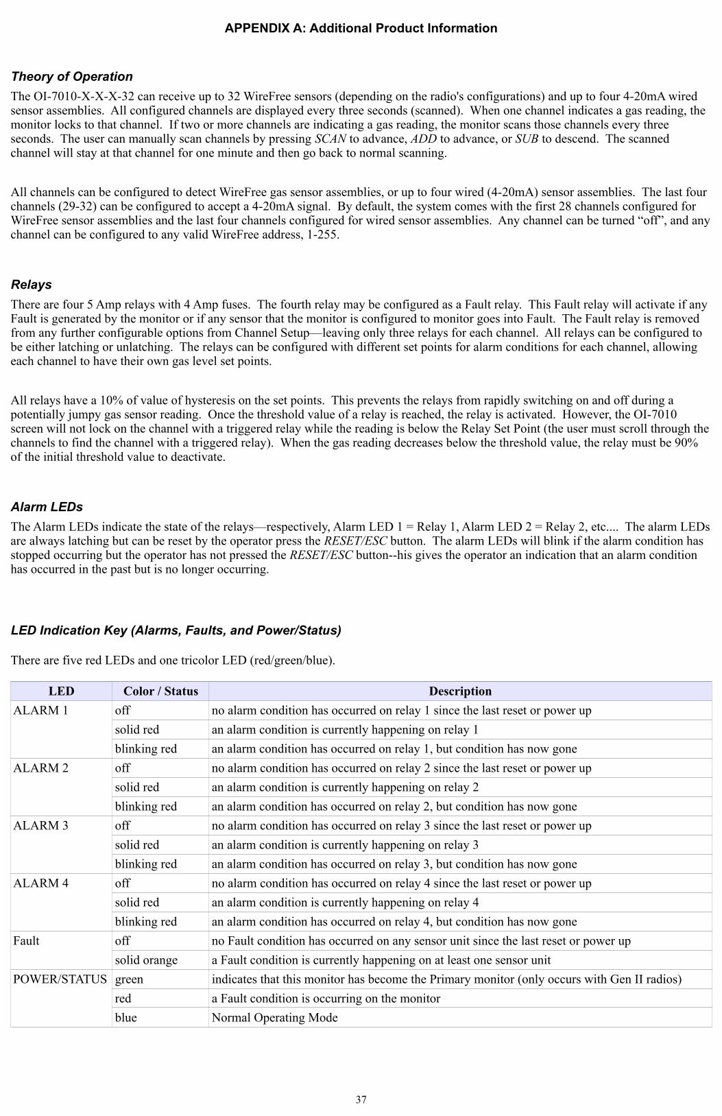
LED Indication Key (Alarms, Faults, and Power/Status)
There are five red LEDs and one tricolor LED (red/green/blue).
LED Color / Status Description
ALARM 1 off no alarm condition has occurred on relay 1 since the last reset or power up
solid red an alarm condition is currently happening on relay 1
blinking red an alarm condition has occurred on relay 1, but condition has now gone
ALARM 2 off no alarm condition has occurred on relay 2 since the last reset or power up
solid red an alarm condition is currently happening on relay 2
blinking red an alarm condition has occurred on relay 2, but condition has now gone
ALARM 3 off no alarm condition has occurred on relay 3 since the last reset or power up
solid red an alarm condition is currently happening on relay 3
blinking red an alarm condition has occurred on relay 3, but condition has now gone
ALARM 4 off no alarm condition has occurred on relay 4 since the last reset or power up
solid red an alarm condition is currently happening on relay 4
blinking red an alarm condition has occurred on relay 4, but condition has now gone
Fault off no Fault condition has occurred on any sensor unit since the last reset or power up
solid orange a Fault condition is currently happening on at least one sensor unit
POWER/STATUS green indicates that this monitor has become the Primary monitor (only occurs with Gen II radios)
red a Fault condition is occurring on the monitor
blue Normal Operating Mode
37

OI-7010-X-X-X-32 Troubleshooting Guide
Fault 1 (F1)
Reason: The top card has lost communication with the digital sensor board (the board potted into the sensor housing).
Solution: Check the connections and/or try new digital sensor board
Applies to: OI-6000-X sensor assemblies
Fault 3 (F3)
Indication: The Low Power IR sensor is beyond repair.
Solution: The sensor must be replaced.
Fault 4 (F4)
Reason: The top card is losing communication to the analog sensor board
Indication: On OI-6000-X units, F4 means that the Analog to Digital Conversion (ADC) on the analog sensor board is not communicating to the digital sensor board.
Solution: Check the orientation of the analog sensor board and/or try a new analog sensor board.
Indication: On the OI-6900-X and OI-6975-X units F4 means the top card is not communicating with the analog sensor board.
Solution: Check the connections from the top card all the way to the analog sensor board. If that does not fix the fault, try replacing the analog sensor board and/or the sensor housing.
Indication: When the sensor element is a Low Power IR sensor the sensor element itself could be the issue. Also, there might not be an issue because sometimes sensor assemblies will show F4 for a few seconds after boot up. This is normal and is due to the boot up of the sensor element itself.
Fault 5 (F5)
Reason: The sensor assembly did not Null correctly
Indication: On positive sensors, if the voltage is above 1 V the sensor will not null. This means there is either gas present or something is wrong with the sensor or sensor board.
NOTE: Positive sensors are all EC sensors not mentioned as a negative sensor.
NOTE: On negative sensors, the sensor assembly should never show “F5”.
Solution: If there is no gas present, replace the sensor element. If that does not work, replace the analog sensor board.
Indication: On the Low Power IR sensor, F5 means that the sensor itself did not null correctly.
Solution: Try again and see if the sensor just had an error. If that does not correct the problem, replace the sensor element. If that does not correct the problem, make sure there is not also an F4 when not trying to null.
Fault 6 (F6)
Reason: The sensor assembly did not Cal correctly with Autocal.
Indication: On the Low Power IR, F6 means that the sensor element did not cal correctly. This could be because there is no gas or even an internal failure.
Solution: Check to make sure there is gas and try again. If that doesn't work, replace the sensor element. If that does not correct the problem, make sure there is no F4 while in normal mode.
For other sensors in which F6 occurs when there is no gas present—or if the sensor assembly is not reading the gas—check to make sure there is gas present. Look on the diagnostic page and make sure the Sensor Voltage is different from the Null Voltage. If the voltage level does not change due to gas, replace the sensor element.
Fault 8 (F8)
Reason: There are two sensors with the same address communicating to the monitor. This could be two different Gen II sensor assemblies, or a Gen I and Gen II sensor assembly. The monitor cannot tell if there are two different Gen I units communicating to the same device with the same address.
Solution: Check all units and make sure they are all using a different addresses.
Fault 9 (F9)
Reason: Radio timeout. This means the monitor has not gotten a communication from the faulting address for over X minutes. X is equal to the radio timeout that is set in the start up menu options. It defaults to 10 minutes.
Solution: Find the sensor assembly and see why it is not communicating. This could be due to a dead battery, broken antenna, bad antenna cable, no antenna, obstacle, weather, etc.
Fault 10 (F10)
Reason: When using a monitor with wired sensor assemblies attached, the sensor is not communicating with the monitor. The problem could be that the sensor assembly is not connected properly, or there may be board issues with the sensor or monitor.
38

Solution: Check all connections. If there is a 4-20mA connection, use a current meter inline to see if the current is correct.
Fault 11 (F11)
NOTE: F11 is now classified as a “warning”, not a Fault. When F11 is occurring, the current reading is still displayed on the OI-7010 Display Screen and analog fault outputs are not triggered.
Reason: The Low Power IR sensor is changing temperature too quickly. Therefore, the reading may be incorrect.
Solution: The sensor will clear once the temperature stops changing too quickly.
Fault 13 (F13)
Reason: When using a monitor with a 4-20mA wired connection, F13 may appear when the sensor assembly is in a fault condition.
Solution: Since it is 4-20mA, the monitor does not know the exact fault condition. Therefore, check the sensor assembly to see what the fault is and then consult other items in this chart for a solution.
Fault 15 (F15)
This fault is no longer assigned. If “F15” is displayed on a sensor assembly, the firmware should be updated.
39

APPENDIX B: 4-20mA Loop Current Introduction
4-20mA Current Loop Introduction
This appendix in only an introduction. The information should serve as a brief overview of 4-20mA, and should not be considered a complete reference for proper implementation or use.
Prior knowledge of industry standards pertaining to 4-20mA specifically, and other aspects of electronics, are assumed to be known by the technician. For proper connection to a monitor or PLC, refer to the manufacturer's specific Operation Manual or instructions for that particular piece of hardware.
Overview
4-20mA ("four to twenty”), is an analog electrical transmission standard used by Otis Instruments for some of its ambient gas sensors and monitors. The signal is a current loop where 4mA represents zero percent signal, and 20mA represents 100 percent signal (full scale of the sensor assembly). The relationship between the current loop and the gas value is linear.
The 4mA allows the receiving monitor/PLC to distinguish between a zero signal, a broken wire, or a dead instrument. Benefits of 4-20mA convention are that it is: an industry standard, low-cost to implement, can reject some forms of electrical noise, and the signal does not change value around the “loop” (as apposed to a voltage). Only one current level can be present at any time; each device which operates via 4-20mA must to wired directly to the monitoring device.
Calculations
I 4−20= 16⋅value scale 4
I 4−20 : current of loop, measured in mA value : PPM or %, of gas concentration scale : full scale of sensor (see below for usual ranges)
Table – Gas Sensor Details
Actual ranges may vary with our product. If unsure, confirm with the actual gas sensor assembly distributor, Otis Instruments sales representative, or call the main Otis Instruments office for more details.
Measuring Current
If the value measured is 0mA, then: the loop wires are broken, the sensor assembly is not powered up, the sensor assembly is malfunctioning, or the monitor is malfunctioning. A DMM (digital multi meter) or Current Meter may be used to test a 4-20mA signal. Place the DMM or Current Meter in line with the loop and measure current. The DMM/Current Meter may be used in conjunction with the normal monitoring device.
40
Target Gas Range Temp.H2S = Hydrogen Sulphide 0-100 ppm -20 to 50C
O2 = Oxygen 0-25 % -30 to 55CSO2 = Sulfur Dioxide 0-20 ppm -20 to 50CCL2 = Chlorine 0-10 ppm -20 to 50CH2 = Hydrogen 0-4 % -20 to 40C
NH3 = Ammonia 0-100 ppm -40 to 40CCO = Carbon Monoxide 0-999 ppm -20 to 50CF2 = Florine 0-1 ppm -10 to 40CHF = Hydrogen Fluoride 0-10 ppm -10 to 40C
H2S-2 = Hydrogen Sulphide 0-100 ppm -40 to 50C(extended temp)

APPENDIX C: Modbus Information
The complete OI-7010 Modbus Register Map may be downloaded from the “Service” section of our website (www.otisinstruments.com).
Modbus Terms
Modbus: RTUSetting: Baud Rate = 9600Data Bits: 8Parity: NoneStop Bits: 1Time Out: 1000 msDevice Address: 1-247 Data Type: Holding RegistersStart Address: The first register the user would like to view (must be between 1-255)Length: Depends on the number of addresses the user would like to viewScan Rate:1000 msData Format: Hex, Decimal, Float
41

APPENDIX D: Operation of Relays
Relays are offered in certain Otis Instruments devices for the purpose of activating alarms, horns, and other equipment upon the detection of gas.
There are two key terms to remember when using relays.
• Deactivated: refers to a relay is in its normal state
• Activated: refers to a relay in the event of an alarm
“Dry” Contact and “Wet” Contact Relays
In regard to power, there are two types of relays.
1. Dry Contact Relays: This type of relay does not provide power to the equipment attached to it (i.e. if there is a light hooked up to this type of relay, it must be powered by another source).
2. Wet Contact Relays: This type of relay does provide power to the equipment attached to it (i.e. if a light was hooked up to this type of relay, it would be powered by the relay). When using a Wet Contact Relay, power should run through the “COMM” terminal to the end equipment.
Drawing 1: "Dry" Contact Relay Configured as a “Wet” Contact
Both the Wet Contact and Dry Contact Relays can be further broken into their connection type.
Normally Open and Normally Closed Relays
There are two different connection types used in Otis Instruments products:
1. Normally Open (NO): when the relay is deactivated, it is “open”. When a signal is received to activate the relay, the connection will “close”—providing a closed circuit. This will allow whatever device that is connected (strobe, horn, etc) to be activated (turned on) when a signal is sent to the relay to activate it. This is the most common configuration. It can be used to set off an alarm or strobe light to indicate that there is an issue.
2. Normally Closed (NC): when the relay is deactivated, it is “closed”. When a signal is received to activate the relay, the connection will “open”—providing an open circuit. This will allow whatever device that is connected to the relay to be deactivated (turned off) when a signal is sent to the relay to activate it. Ex: If there was a powered light connected to this relay to indicate that the system was up and running, when the signal to activate the relay is sent the light will turn off. Therefore, the user is made aware that there is an issue.
If a light was connected in the NO configuration with the default setting (not failsafe), then the light would not turn on in the event of a power loss. If the light was used in the NC configuration, the light would stay lit (provided the light is powered by a different source).
Failsafe Relays
There is an option in Otis Instruments devices to set the relays as “failsafe” or “not failsafe”. This refers to what type of signal is being sent through the relay, which can be a “high” or a “low” (on or off). The default setting is “not failsafe”, which means that the devices will operate as described above.
Failsafe mode was introduced to be able to show a change in state (or alarm) in the event of a power loss. If the NO configuration was used in failsafe mode, it could indicate that there was a power loss by turning off of a light.
If the “failsafe” setting is used, the relays will behave as follows:
1. Normally Open (NO): when the relay is deactivated, it is “closed”. When a signal is received to activate the relay, the connection will “open”—leaving
42
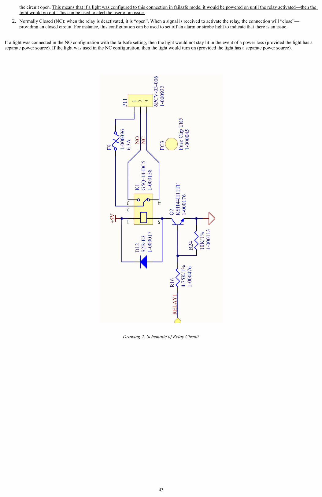
the circuit open. This means that if a light was configured to this connection in failsafe mode, it would be powered on until the relay activated—then the light would go out. This can be used to alert the user of an issue.
2. Normally Closed (NC): when the relay is deactivated, it is “open”. When a signal is received to activate the relay, the connection will “close”—providing an closed circuit. For instance, this configuration can be used to set off an alarm or strobe light to indicate that there is an issue.
If a light was connected in the NO configuration with the failsafe setting, then the light would not stay lit in the event of a power loss (provided the light has a separate power source). If the light was used in the NC configuration, then the light would turn on (provided the light has a separate power source).
Drawing 2: Schematic of Relay Circuit
43

Specifications
Operating Voltage: 12-35 Volts DC, 110/240 VAC
Compatibility: Otis WireFree and wired (4-20mA input) sensor assemblies
Channels: 32
Gases: All that are supported by Otis sensor assemblies
Wired Output: RS-485 Modbus
Relays: Four dry-contact with 4 Amp Fuses
Protection: Power EMI filter, surge suppression, 4-20mA and RS-485 surge suppression
Operating Temperature: -22° F to 158° F; -30° C to 70° C
Current Draw: 175mA at 24 VDC (monitor without sensor assemblies); 6.6 Watts max
Radio Options: Can be configured with up to two radios (one Legacy and one Gen II):· 900 MHz (Legacy Option), 250mW· 2.4 GHz, ISM, 125mW· 900 MHz, 200mW
Display Two graphical LCD (128 x 64), transflective, sunlight readable, LED backlight
Enclosure: Stahlin, fiberglass, clear window 10” x 8” x 6” (25.4 cm x 20.32 cm x 15.24 cm) 10 lbs (4.54 kg)
Mounting: 4 mounting feet; 6” W x 12-1/4” T5/16” or 8mm diameter MAX mounting bolt/screw size
Certifications: NEMA 4 (enclosure only)
Warranty: Hardware: 1 year (limited)
44

Warranty Statement for WireFree ProSafe OI-7010-X-X-X-32
Hardware
Otis Instruments, Inc. (Manufacturer) warrants its products to be free of defects in workmanship and materials—under normal use and service—from the date of purchase from the manufacturer or from the product's authorized reseller. The hardware for this device is under a one-year limited warranty.
The manufacturer is not liable (under this warranty) if its testing and examination disclose that the alleged defect in the product does not exist or was caused by the purchaser's (or any third party's) misuse, neglect, or improper installation, testing or calibrations. Any unauthorized attempt to repair or modify the product, or any other cause of damage beyond the range of the intended use, including damage by fire, lightening, water damage or other hazard, voids liability of the manufacturer.
In the event that a product should fail to perform up to manufacturer specifications during the applicable warranty period, contact the product's authorized reseller or return the product directly to the manufacturer with a Return Material Authorization (RMA). This number will be assigned upon contacting our service department at 903.566.1300 or [email protected]. The manufacturer will--at its option and expense--repair or replace the product, or deliver an equivalent product or part to the purchaser at no additional charge.
Any replaced or repaired product or part has either a 90-day warranty or the remainder of the initial warranty period (whichever is longer).
45

Otis Instruments, Inc.301 S Texas Ave.
Bryan, TX 77803
Service Department: 903.566.1300
Corporate Office: 979.776.7700
www.otisinstruments.com
46