model: pl-ps-8 operation
TRANSCRIPT

Automation and Chlorination
Operation Manualfor models
PL-PS-4 PL-PS-8-VPL-PS-8 PL-PS-16-VPL-PS-16
Qua
rterly
Mon
thly
Wee
kly
Free Chlorine 1.0 - 3.0 ppm pH 7.2 - 7.8
Raise desired output % toincrease, lower desired output %to decrease -OR- increase ordecrease pump filtration time.
Too low - add soda ash.Too high - add muriatic acid
Alkalinity 80 - 120 ppm
Salt 2700 - 3400 ppm Add salt as required to increase.
Add baking soda to increase.
Stabilizer 60 - 80 ppm Add cyanuric acid to increase.
Calcium 200 - 400 ppm Add calcium to increase. Electrolytic Cell inspect & clean Refer to section in manual.
TEST IDEAL RANGE ADJUSTMENT REQUIRED
Drain and add water to decrease.
Add acid as required to decrease.
Pro Logic
092331D RevGCopyright © 2010 Hayward www.hayward.com
620 Division St.Elizabeth, NJ 07207

IMPORTANT SAFETY INSTRUCTIONS
When using this electrical equipment, basic safety precautions should alwaysbe followed, including the following:
• READ AND FOLLOW ALL INSTRUCTIONS
• ! WARNING: Disconnect all AC power during installation.
• ! WARNING: Water in excess of 100 degrees Fahrenheit may behazardous to your health.
• ! WARNING: To reduce the risk of injury, do not permit children touse this product unless they are closely supervised at all times.
• A green colored terminal marked “Grounding” is located inside the wiringcompartment. To reduce the risk of electric shock, this terminal must beconnected to the grounding means provided in the electric supply servicepanel with a continuous copper wire equivalent in size to the circuitconductors supplying the equipment.
• One bonding lug for US models (two for Canadian models) is provided on theexternal surface. To reduce the risk of electric shock, connect the localcommon bonding grid in the area of the swimming pool, spa, or hot tub tothese terminals with an insulated or bare copper conductor not smaller than 8AWG US / 6 AWG Canada.
• All field installed metal components such as rails, ladders, drains, or othersimilar hardware within 3 meters of the pool, spa or hot tub shall be bondedto the equipment grounding bus with copper conductors not smaller than8 AWG US / 6 AWG Canada.
• SAVE THESE INSTRUCTIONS
48
LIMITED WARRANTY (effective 03/01/12) Hayward warrants its Pro Logic, OnCommand and E-Command pool automation products as well as its Aqua Rite, Aqua Rite Pro, Aqua Plus and SwimPurechlorination products to be free of defects in materials and workmanship, under normal use and service, fora period of three (3) years. Hayward also warrants its Aqua Trol chlorination products to be free of defectsin materials and workmanship, under normal use and service for a period of one (1) year. These warrantiesare applicable from the initial date of purchase on private residential swimming pools in the US and Canada.Installations of product for use on commercial pools in the US and Canada is covered for a period of one (1)year for defects in materials and workmanship. Hayward warrants all accessories and replacement partsfor the above-identified pool automation and chlorination products for a period of one (1) year. Accessoriesalso include remotes, actuators, base stations, temperature sensors, flow switches and chemistry probes.Each of these warranties is not transferable and applies only to the original owner.
Hayward shall not be responsible for cartage, removal, repair or installation labor or any other such costsincurred in obtaining warranty replacements or repair.
Proof of purchase is required for warranty service. If written proof of purchase is not provided, themanufacturing date code will be the sole determinant of the date of installation of the product. To obtainwarranty service or repair, please contact the place of purchase or the nearest Hayward authorized warrantyservice center. For more information on authorized service centers please contact the Hayward TechnicalService Support Center (61 Whitecap Road, North Kingstown RI, 02852) or visit the Hayward web site atwww.hayward.com.
WARRANTY EXCLUSIONS:
1. Material supplied or workmanship performed by others in process of installation.
2. Damage resulting from improper installation including installation on pools larger than the product rating.
3. Problems resulting from failure to install, operate or maintain the product(s) in accordance with therecommendations contained in the owners manual(s).
4. Problems resulting from failure to maintain pool water chemistry in accordance with the recommendationsin the owners manual(s).
5. Problems resulting from tampering, accident, abuse, negligence, unauthorized repairs or alternations, fire,flood, lightning, freezing, external water, degradation of natural stone used in or immediately adjacent to apool or spa, war or acts of God.
6. Use of a non-genuine Hayward replacement salt chlorination cell on any Hayward automation or chlorinationproduct will void the warranty for that product.
The express limited warranty above constitutes the entire warranty of Hayward Pool Products with respectto its products and is in lieu of all other warranties expressed or implied, including warranties of merchantabilityor fitness for a particular purpose. In no event shall Hayward Pool products be responsible for anyconsequential, special or incidental damages of any nature. Some states do not allow a limitation on howlong an implied warranty lasts, or the exclusion of incidental or consequential damages, so the above limitationmay not apply to you. This warranty gives you specific legal rights, and you may also have other rights,which vary from state to state.

Table of Contents
System Overview Block Diagram....................................................................... 1Automation............................................................................. 1Chlorination............................................................................ 2Default Display...................................................................... 2
Manual System Output Names........................................................................ 3Operation Filter Pump............................................................................. 3
Lights and Aux Outputs.......................................................... 4Pool/Spa Valves..................................................................... 4Heaters................................................................................... 5System Off............................................................................. 5Service................................................................................... 5
Automatic System Using the Programming Buttons.......................................... 6Operation Programming Menu Flow Chart........................................... 7(Programming) Settings Menu........................................................................ 8
Timers Menu.......................................................................... 12Group Function...................................................................... 15Configuration Menu............................................................... 17Maintenance Menu............................................................... 32
Quick “How To” Operate the Spa - Manually.................................................. 33Guide Operate the Spa - Automatically.......................................... 33
Set the Heater Temperature................................................. 33Set the Chlorinator Output ................................................... 33Start/Stop Superchlorination................................................ 34Program a Timeclock............................................................ 34Program a Countdown Timer............................................... 34Enter/Exit Service Mode....................................................... 34
Chlorinator Operation/ Saturation Index..................................................................... 35Water Chemistry Salt Level................................................................................ 36
Type of Salt............................................................................ 36How to Add or Remove Salt................................................. 36
System Maintenance Servicing and Cleaning the Chlorinator Cell....................... 39Winterizing.............................................................................. 39Spring Startup........................................................................ 39
Troubleshooting & Service Mode ....................................................................... 40Diagnostic Information Check System Indicator........................................................ 40
Diagnostic Menu................................................................... 42
Warranty Pro Logic Warranty................................................................ 48
47

1
System OverviewThe Hayward Pro Logic is a multifunction pool controller used to fully manage your pool/spa system. The ProLogic can control pumps, valves, lighting, heaters, and chlorination. Although the Pro Logic is easy to use, it isimportant to completely read through this operating manual before attempting to operate the control.
NOTE: This manual assumes that the Pro Logic has been wired and configured according to the InstallationManual. Aspects of the Pro Logic that pertain to system setup are not covered in this manual.
AutomationThe PL-PS-4 (-8, -16) can control up to 4 (8, 16) high voltage (120/240V) pieces of equipment, up to 4 (8 for thePS-16) automatic valve actuators, and 2 conventional heaters plus a solar heater. Both manual and automatic(programmed) operation are available. All of the control functions can be programmed at a display/keypad whichis part of the main unit (typically located near the pool equipment) or at one or more remote display/keypads.
46
Water
ExternalInput
Air
Spa(for dual equip)
Solar
ChlorinatorFlow Switch
240 VACPower
240 VACPower
Filter Pump
Lights
Aux
Aux (8)
Pool/Spa Suction &Return Valves
General PurposeValves (2)
General PurposeValves (4)
Heaters (2)
Chlorinator Cell
Circuit BreakerSubpanel
Circuit BreakerSubpanel
Main DisplayKeypad
Optional WiredRemote Display
Keypad(maximum of three)
Optional WirelessRemote Display
Keypad
Optional WirelessSpaside Remote
TemperatureSensors
120/240VRelays
120/240VRelays
24V ValveActuators
24V ValveActuators
INPUT OUTPUT
OUTPUT
OptionalWireless Base
Receiver
LDLINE
CO NTRO LS I NC.G
POOL SPA
ON OFF
ON OFF
ON OFF
ON OFF
ON OFF
VALV ES
FILTER
HE ATE R
LIGHTS
AUX1
AUX2
(2 for PS-4)(6 for PS-8, PS-16)
EXPANSION UNIT
PS-4 (-8, -16) MAIN UNIT
(used with PS-16 only)

2
ChlorinationWhen the chlorinator function is enabled (requires a chlorinator cell and P-KIT sold separately), the Pro Logic isalso an automatic chlorine generation system for pool and/or spa sanitization. If enabled (see Configuration Menu),this operation requires a low concentration of salt (sodium chloride) in the pool/spa water. The Pro Logic auto-matically converts the salt into free chlorine which kills bacteria and algae in the pool/spa. Chlorine will revert backto sodium chloride after killing bacteria. These reactions will continuously recycle, virtually eliminating the need toadd sanitizing chemicals to your pool/spa. The only time you may need to add more salt to the pool/spa is whenwater is replenished due to backwashing, draining, or splashing (not evaporation).
The Pro Logic is designed to handle the purification needs of most residential swimming pools up to 40,000 gallons(150,000 liters), or the needs of most commercial pools up to 25,000 gallons (95,000 liters). Check local codesfor other restrictions. The actual amount of chlorination required to properly sanitize a pool varies due to batherload, rainfall, temperature, and the pool’s cleanliness.
For pools larger than 40,000 gallons, the Pro Logic can control one or more Hayward Aqua Rite chlorinators tosupplement chlorine production.
NOTE: Before installing this product as part of a saline water purification system in a pool or spa using naturalstone for coping or for immediately adjacent patios/decking, a qualified stone installation specialist should beconsulted regarding the appropriate type, installation, sealant (if any) and maintenance of stone used around asaline pool with electronic chlorine generator in your particular location and circumstances.
NOTE: The use of dry acid (sodium bisulfate) to adjust pool pH is discouraged especially in arid regions wherepool water is subject to excessive evaporation and is not commonly diluted with fresh water. Dry acid can cause abuildup of by-products that can damage your chlorinator cell.
Default DisplayTurn power on at the main panel and turn the Pro Logic control power circuit breaker on. The keypad will showthe default display. The default display alternates between the day/time, air and pool (or spa) temperature, pool/spa sanitizer setting, and salt level. Under certain circumstances, additional displays may be added to the defaultmenu to inform you about system operation. Refer to the Programming Menu Flowchart on page 7 to view allpossible displays. The Pro Logic will automatically scroll through all of the available default menu displays or youcan press “<” or “>” to manually scroll.
Optional Remote Display/keypad shown--the display keypad on themain control unit will have a “Service” button in the upper left
corner instead of the “System Off” button.
45

3
Manual System OperationWhile the main objective of the Pro Logic is to automate the operation of your pool/spa system, there may becertain times when you want to override the automatic operation and control the equipment manually. To operatethe pool equipment manually while keeping the automation active, perform the following procedures. Note that ifyou turn a relay on manually, it will remain on until either you turn it off manually, or the next time the programmedautomatic operation would normally turn that relay off. Example: the filter pump is programmed to run from 9:00Ato 5:00P daily. If you turn the filter pump on manually at 8:00PM, it will run continuously until the next day at5:00PM at which time it will turn off and follow the normal program from then on. Manually turning off a relayworks in a similar fashion.
Output NamesThe Pro Logic is shipped from the factory with each output labeled with a generic name (e.g. AUX1, VALVE3,etc.). One of the features in the software (see Configuration Menu, page 17) is that each output can be assigned anew name that is more descriptive of the equipment being controlled. This makes it much easier to operate all of theequipment on your pool without having to memorize what each output controls. Insert name labels are also pro-vided to be placed next to each display pushbutton. Since there is no way to know how your particular system isconfigured, this manual will use the original generic names for each output.
Pool Filter PumpThe pool filter pump can be manually operated whether in Standard (single pump) or Dual Equipment (separatepumps for both pool and spa) mode. When in Standard mode, the display will refer to the pool filter pump as“FILTER”. When in Dual Equipment mode, the display will read “POOL FILTER”.
Single Speed Filter Pump: If the pump is currently off, press the “FILTER” button to turn on the pump. Pressingthe “FILTER” button again will turn off the pump. However, if there is a heater in the system, and it is operating,and the “Heater Cooldown” feature is enabled (Configuration Menu) then: when you press the “FILTER” buttonto turn off the filter, only the heater will turn off, the “FILTER” LED will flash and the display will indicate “HeaterCooldown”. At this point the filter pump will automatically turn off after 5 minutes of heater cooldown operation.If you want to override the heater cooldown, simply press the “FILTER” button again to turn off the filter pump.
44
Aux1 - Aux6(On/Off)
Check System LED
Menu and Navigation Buttons
Display
Valve4 or Heater2(See Configuration Menu)
System Off (remote displays)or
Service (main unit display)
If the sensor appears to operating properly, then the temperature will be displayed. If this temperatureis not correct then check the placement of the sensor. If the problem is not placement related, then thesensor will, most likely, require replacement. If the display is “Open Circuit” or “Short Circuit” thencheck the wiring to the sensor and also make sure that the wires are secure in the terminal block in thePro Logic main unit.
VSP Speed/Power
Filter
± to viewPush to view the actual speed and power reported by the VSP
No functionMove to previous/next menu item
Move to previous/next menu item
if Gen 2 VSPs are detected
Main SoftwareRevision 4.00
Display Softwareremote-08 r3.10
Exp. Unit SoftwareRevision 1.10
RF Base Softwarer1.20 ID:1234
Pool Filter VSCSoftware r1.00
Pool Filter BridgeSoftware r1.00
6B Spa SoftwareRemote A r1.00
Pool Filter DriveSoftware r1.00
Pool Filter DisplaySoftware r1.00
Digital Spa SoftwareRemote B r1.00
CL Module SoftwareRevision 1.00
CL Light Software+ to view
CL LT1 SoftwareApp:1.00 BL:1.02
No function
No function
No function
No function
No function
No function
No function
No function
No function
No function
No function
Press to view the software revisions of detected lights
Press to view the software revisions of detected lights
Move to previous/next menu item
Move to previous/next menu item
Move to previous/next menu item
Move to previous/next menu item
Move to previous/next menu item
Move to previous/next menu item
Move to previous/next menu item
Move to previous/next menu item
Move to previous/next menu item
Move to previous/next menu item
Move to previous/next menu item
Move to previous/next menu item
Move to previous/next ColorLogic 4.0 light/menu item
Chemistry SenseSoftware r1.00
VSP Software± to view
No function
Push to view the software revision of the connected VSPs
Move to previous/next menu item
Move to previous/next menu itemif TriStar VSPs are detected
if TriStar VSPs are detected
if EcoStar VSPs are detected
if EcoStar VSPs are detected
Available displays depend on configuration. If you call the Hayward Technical Service Dept. forassistance, they may ask for the software revisions of both the main unit and each of the display/keypads or other devices that are attached to the system. Note that it is possible that differentdisplay/keypads have different software revision levels. For this reason, it is advisable to check thisdiagnostic menu item on every display.

4
Two Speed Filter Pump: If the pump is currently off, simply press the “FILTER” button to turn on high speedoperation of the filter pump. The “Filter” LED will illuminate continuously. Pressing the “FILTER” button again willswitch to low speed operation and the “FILTER” LED will flash. Note that if the pump has been off for more than30 seconds, it will run at high speed for 3 minutes regardless of selection. This high speed operation helps allow thepump to prime and establish normal water flow.
Variable Speed Filter Pump: If the pump is currently off, press the “FILTER” button to turn the filter pump on tothe last speed (1, 2, 3, or 4) that was used. A temporary display is generated indicating the current speed selection(Filter On:Spd 1). Pushing the “+” or “-” button changes the speed selection. If the pump has been off for morethan 30 seconds, it will run at the highest speed for 3 minutes regardless of selection. This high speed operationhelps allow the pump to prime and establish normal water flow.
Freeze Protection: This function protects the pool, plumbing, and equipment against freeze damage. If FreezeProtection is enabled and the AIR temperature sensor falls below the preset freeze protection temperature (seeFilter Configuration), the Pro Logic will turn on the filter pump to circulate the water.
Spa Filter Pump (when using Dual Equipment)Single Speed Filter Pump: If the pump is currently off, press the “AUX1” button to turn on the pump. Pressingthe “AUX1” button again will turn off the pump. However, if there is a heater in the system, and it is operating, andthe “Heater Cooldown” feature is enabled (Configuration Menu) then: when you press the “AUX1” button to turnoff the filter, only the heater will turn off, the Filter LED will flash and the display will indicate “Heater Cooldown”.At this point the filter pump will automatically turn off after 5 minutes of heater cooldown operation. If you want tooverride the heater cooldown, simply press the “AUX1” button again to turn off the filter pump.
Two Speed Spa Filter Pump: If the pump is currently off, simply press the “AUX1” button to turn on high speedoperation of the filter pump. The “AUX1” LED will illuminate continuously. Pressing the “AUX1” button again willswitch to low speed operation and the “AUX1” LED will flash. Note that if the pump has been off for more than30 seconds, it will run at high speed for 3 minutes regardless of selection. This high speed operation helps allow thepump to prime and establish normal water flow.
Variable Speed Filter Pump: If the pump is currently off, press the “AUX1” button to turn the filter pump on tothe last speed (1 or 2) that was used. A temporary display is generated indicating the current speed selection (FilterOn:Spd 1). Pushing the “+” or “-” button changes the speed selection. If the pump has been off for more than 30seconds, it will run at the highest speed for 3 minutes regardless of selection. This high speed operation helps allowthe pump to prime and establish normal water flow.
Freeze Protection: This function protects the pool, plumbing, and equipment against freeze damage. If FreezeProtection is enabled and the AIR temperature sensor falls below the preset freeze protection temperature, the ProLogic will turn on the spa filter pump to circulate the water.
Lights and Aux OutputsStandard Relay: Manual operation of all relays (LIGHTS, AUX1 and AUX2 for a PS-4 model, LIGHTS, AUX1- AUX6 for a PS-8 model, or LIGHTS, AUX1 - AUX14 for a PS-16 model) is identical. Assuming that the relayis currently off, simply press the appropriate button to turn on the relay. If the relay does not turn on, it probably isdue to the “interlock” feature (which was set up in the Configuration Menu) being activated that requires the filterpump to be running and the valves to be in the pool-only position. This protects pumps and other equipment frompossible damage. If the controlled output is on, pressing the appropriate button again will turn off the relay.Manual turn off is disabled if the “Freeze Protection” feature is enabled and the air temperature is less than theselected freeze temperature threshold.
Dimmer Relay: If Lights or an Aux output is configured as a dimmer, pressing the corresponding button willgenerate a temporary display which shows the dimmer output level (Off - On 100%). Pushing the “+” or “-”button changes the level in increments of 20%. When the desired output level is displayed, press the correspond-ing button again to turn off the display and return to normal operation. When the Lights or Aux output comes onagain (either manually or automatically), the dimmer output level will be the same as the last time that it was set.
ColorLogic Relay: This selection will only appear if an optional ColorLogic Network Module (AQL-COLOR-MODHV) is detected at startup. The Network Module allows the Pro Logic to control custom colors and lightshows in Hayward Generation 4 or later ColorLogic pool and spa lights. Refer to the AQL-COLOR-MODHVmanual for details on how to configure an Aux output for use with these lights. If a ColorLogic Module is detectedat power up, the Lights relay is under automatic control and is used to power the ColorLogic lights.
43
If a conventional or solar heater is operating, it is likely that the temperature of the water at the cell ishigher than the pool/spa water temperature displayed on the Pro Logic default display.
Instant Salt3200 PPM (+=save) Move to previous/next menu item
Press to load the “Instant Salt” into the averaged salt display
This display will be shown only if the chlorinator is enabled. This display shows “Instant Salt” or“Instant Minerals” (if Chlor. Config. is set for “Display Minerals”). The “Instant Salt” is calculatedbased on the voltage, current (amps), and water temperature at the cell. This is different than the“average salt” value which is displayed as part of the default menu. There are a number of reasonswhy instant and average salt readings may differ. Some of these include salt having just been addedto the pool and not yet thoroughly mixed, calcium buildup on the cell, and the cell aging.
pH 7.5 (On)ORP 700 mV (On)
No functionMove to previous/next menu item
if AQL-CHEM is used
This display will be shown only if sensing is enabled. This display shows both pH and ORP levels/status when chemistry sensing is enabled via the Chemistry Configuration Wizard (requires the use ofAQL-CHEM Sensing Kit). The Pro Logic will refer to these levels to determine how much chlorine togenerate (ORP) and, if using an AQL-CHEM2 dispense kit, how much CO2 or acid to dispense (pH).Refer to the AQL-CHEM manual for specific information about these levels as well as the recommendedranges.
Flow SwitchFlow
No functionMove to previous/next menu item
This display will be shown only if the chlorinator is enabled. The current status of the flow switch isdisplayed. There is a short delay when transitioning from flow to no-flow and a longer delay on thetransition from no-flow to flow. The delay time is displayed.
Air Sensor94ºF
Cell Temp Sensor77ºF
Solar SensorShort circuit
Water SensorOpen circuit
Spa SensorOpen circuit
No function
No function
No function
No function
No function
Move to previous/next menu item
Move to previous/next menu item
Move to previous/next menu item
Move to previous/next menu item
Move to previous/next menu item
NOTE: If Pool and Spa-Dual is selected, the water sensor will display as “Pool Sensor”.
Displays actual speed (in % or RPM) and power consumption (in Watts) as reported by the selectedVSP.

5
VSP Relay: This selection is used to configure a Lights/Aux output to supply power and control a HaywardVariable Speed pump (VSP).
Pool/Spa ValvesPool-only or Spa-only systems: The POOL/SPA/SPILLOVER button has no function.
Standard Pool and Spa systems without spa spillover: In pool-only mode (“POOL” LED illuminated), pressthe “POOL/SPA/SPILLOVER” button to switch to spa-only operation (“SPA” LED illuminated). Pressing the“POOL/SPA/SPILLOVER” button again will switch back to pool-only. Note that the filter pump will turn offwhile the pool/spa valves are turning.
Standard Pool and Spa systems with spa spillover: When currently in the pool-only mode (“POOL” LEDilluminated), press the “POOL/SPA/SPILLOVER” button to switch to spa-only operation (“SPA” LED illumi-nated). Press the button again to switch to spa spillover operation (“SPILLOVER” LED illuminated). Pressing the“POOL/SPA/SPILLOVER” button again will switch back to pool-only mode. Note that the filter pump will turnoff while the pool/spa valves are turning.
Dual Equipment Pool and Spa systems without spa spillover: The POOL/SPA/SPILLOVER button has nofunction. The “POOL” LED will always be illuminated.
Dual Equipment Pool and Spa systems with spa spillover: When currently in the separate Pool and Spa loopsmode (“POOL” LED illuminated) and the Spa Filter is off, press the POOL/SPA/SPILLOVER button to switchto spa spillover operation (“SPILLOVER” LED illuminated). Press the POOL/SPA/SPILLOVER button again toreturn to the separate Pool and Spa loops mode of operation. Note that the Pool Filter pump will shut off while thepool/spa return valve is turning. The system will automatically switch out of spillover whenever the spa filter pumpis turned on.
NOTE: For Dual Equipment Pool and Spa systems, there is no Spa Only mode.
HeatersThis description applies to Heater1 and to Heater2, if programmed (note that the function of the Valve4 buttonchanges to Heater2 when Heater2 is enabled). Pressing the “HEATER” button causes the Pro Logic to switch theheater control output between a “forced off” state and a normal, automatic thermostatic control operating state.
System OffEach remote display/keypad has a red “SYSTEM OFF” button on the upper left corner of the keypad. Pressingthis button will turn all outputs off and they will remain off, regardless of any programmed control logic, until eitherthe “SYSTEM OFF” button (on any remote display/keypad) is pressed again or the “SERVICE” button is pressedon the display/keypad at the main unit. The red “SYSTEM OFF” LED will illuminate to indicate that all outputs andbeing forced off.
! WARNING: pressing the “SYSTEM OFF” button overrides any programmed freeze protectionand may cause damage to your system in freezing conditions.
ServiceThe main unit keypad has a “SERVICE” key. This button is used primarily during servicing of the pool equipment.If you want to completely disable the automatic operation and operate the system manually, you can put the systeminto Service or Service-Timed mode by pressing the “SERVICE” button. Pressing the “SERVICE” button oncewill switch the system into service mode which means that all automatic functions are disabled, and the remotedisplay/keypads are disabled (except for manual turn off for emergencies). The red “SERVICE” LED will beilluminated and the Pro Logic will remain in this mode of operation until manually taken out of service mode.
Pressing the “SERVICE” button again will cause the Pro Logic to switch to service-timed mode which is verysimilar to service mode, except that the Pro Logic will automatically return to normal operation after 3 hours.During service timed operation, the “SERVICE” LED will flash and the time remaining will be displayed on theremote display keypad(s).
Pressing the “SERVICE” button again, will return the Pro Logic to normal (automatic) operation. See Trouble-shooting/Diagnostic Information for more information about the service modes.
42
• pH Timeout - Check Feeder -- If the unit has been dispensing pH for more than the selected timeout withoutreaching the desired level. Check the chemical supply and the feeder. If both are OK, the timeout may need tobe increased. Press the “+” button to reset the alarm and resume dispensing.
• pH Calibration Error -- When using the pH Calibration Wizard and the entered test result was different fromthe measured pH level by ± 1.0 or more. The pH probe may need to be cleaned or replaced.
• ORP Probe Error -- If the CSM indicates that there is a problem with the ORP probe.
• ORP Low - Check Chlor -- If an ORP level of 350mV or less is detected. Check the chlorinator for properoperation.
• ORP High - Check Chlor -- If an ORP level of 950mV or higher is detected. Check the chlorinator for properoperation.
• ORP High - Chlor Off -- If an ORP level of 950mV or higher is detected and the chlorine feed mode is ORPAuto Sensing, the chlorinator has been turned off. Check the chlorinator for proper operation.
• ORP Timeout -Chlor Off -- If the unit has been chlorinating for more than the selected sanitizer timeoutwithout reaching the desired level, the chlorinator has been turned off. Press the “+” button to reset the alarmand resume chlorination.
• Ambient Sensor-- If the Pro Logic internal temperature sensor is either an open or short circuit.
For helpful troubleshooting information on any of these issues, go to the Diagnostic Menu and then scroll throughthe various items until you see the cause for the “CHECK SYSTEM” LED being illuminated.
Diagnostic MenuTo enter the Diagnostic Menu, press the “Menu” button repeatedly until the display shows “Diagnostic Menu”. Atthis point, you can use either the “<” or “>” buttons to scroll through the various menu items which are describedbelow:
Set Day and TimeWednesday 10:37P Move to previous/next menu item+23.45 +6.75A84°F 3200PPM
Press to switch chlorinator operation to opposite polarity (15 second delay)
+/- 23.45V is the voltage applied to the chlorinator cell+/-6.75A is the current (amps) through the cell84ºF is the water temperature at the cell3200PPM is the “instant” salt level at this time
This display will be shown only if the chlorinator is enabled. For the chlorinator to be operating,several other things must be happening: the filter pump must be running, the flow switch must bedetecting flow, the chlorinator setting must be set greater than 0%, the water temperature at the cellmust be between 50ºF and 140ºF, and the salt level must be within the operating range. If any of theseconditions are not met, the chlorinator diagnostic display will tell you the reason. It’s possible to havemore than one reason, in which case after you rectify what was displayed the first time, a seconddisplay will appear.
If the current (amps) display is 0.00A, then the chlorinator is operating normally but is in the off partof its normal operating cycle. Simply press either the “+” or “-“ key to start a new cycle.
The Pro Logic periodically reverses the polarity of the voltage applied to the cell in order to automaticallyclean off any calcium deposits. It is important that you check the chlorinator operation in bothpolarities. To do this, press either the “+” or “-“ buttons and the chlorinator will turn off, wait for 15seconds and then turn on in the opposite polarity.

6
Automatic System OperationThe Pro Logic controls most of your pool equipment automatically in order to minimize the time spent working onyour pool. Most of the pool equipment can be programmed to operate on a timeclock basis. In addition, thedesired pool and spa temperatures and pool and spa chlorinator settings can be programmed. This section willguide you on how to program the automatic operation for each function.
The programming of automatic functions can be performed at either the main display/keypad located at the poolequipment pad or the in-home remote display/keypad.
Using the programming buttonsThere are 5 buttons on each keypad that are used for programming (refer to diagram).
There are 4 steps to programming any function:
1. Press the “MENU” button to get to the desired menu. Multiple pushes of the button willrotate through all 6 menus and return to the starting point.
2. Press either key to scroll through the various items in the selected menu. Multiple pushesof the button will rotate through all menu items and return to the starting point. Only menuitems that are applicable to your pool will appear. (Example: if you don’t have a spa, thenno spa related menu items will appear).
3. Once a menu item has been selected above, the current setting/selection will appear (flashing)on the display. Use the “+” and/or “-” keys to change this selection. Sometimes “+” and“-“ will adjust a value up or down (example: heater temperature setting or timeclock on/offtime). In this case, pushing the “+” or “-” will change the value by one increment andholding the “+” or “-” button in for more than one second will make the values auto scroll.In other cases, the “+” and “-“ may toggle between 2 options (example: turningsuperchlorination ON or OFF).
4. After you have adjusted the item to the desired value, simply move on to the next menuitem to “lock in” your new setting. The Pro Logic memory will maintain the setting, even ifpower is removed for an extended period.
ButtonSelect Desired Menu
and Buttons
and Buttons
Select Items froma Menu
Adjust
41
• PS-16 Communication Error -- If an PL-PS-16 and the Expansion Unit is not responding.
• Low Volts -- If the chlorinator cell voltage is too low.
• No Cell Power -- If no chlorinator cell power is detected on the printed circuit board.
• Chk Flow Switch -- If the flow switch input is invalid.
• Cell Power Error -- If a chlorinator cell power error is detected on the printed circuit board.
• No Flow-Filter Pump -- If the filter pump is on and the flow switch indicates no flow for 15 minutes or more.
• Cell Missing -- If the chlorinator is enabled but no cell is detected.
• Pool Filter VSP Comm Error-- If variable speed is selected for the Pool Filter and the Hayward VSPinterface is not responding.
• Pool Filter VSP Drive Comm Error -- If variable speed is selected for the Pool Filter and the Hayward VSPdrive controller is not responding.
• Pool Filter VSP Err: x -- If variable speed is selected for the Pool Filter and the Hayward VSP is indicatingand error. x is the same decimal error displayed by the VSP itself.
• Spa Filter VSP Comm Error -- If variable speed is selected for the Dual Equipment Spa Filter and theHayward VSP interface is not responding.
• Spa Filter VSP Drive Comm Error -- If variable speed is selected for the Dual Equipment Spa Filter and theHayward VSP drive controller is not responding.
• Spa Filter VSP Err: x -- If variable speed is selected for the Dual Equipment Spa Filter and the Hayward VSPis indicating and error. x is the same decimal error displayed by the VSP itself.
• Aux1 VSP Comm Error -- If variable speed is selected for the Aux1 relay type and the Hayward VSPinterface is not responding.
• Aux1 VSP Drive Comm Error -- If variable speed is selected for the Aux1 relay type and the Hayward VSPdrive controller is not responding.
• Aux1 VSP Err: x -- If variable speed is selected for the Aux1 relay type and the Hayward VSP is indicatingand error. x is the same decimal error displayed by the VSP itself.
For Pool Filter, Spa Filter and Aux using Gen2 EcoStar Variable Speed Pumps only:
• Main Voltage is too low• Main Voltage is too high• Remote Stop was pressed (Press “+” to restart)• Prime Failed (Press “+” to restart)• Failed to start (Press “+” to restart)• Pump has stalled (Press “+” to restart)• SVRS tripped (Press “+” to restart)• Drive failure (see Pump Display)
• CSM Comm Error: -- If Chemistry Sensing is enabled and the Chemistry Sense Module (CSM) is notresponding.
• pH Probe Error -- If the CSM indicates that there is a problem with the pH probe.
• pH Low - Check Feeder -- If a pH level of 6.9 or less is detected, check the feeder for proper operation
• pH High - Check Feeder -- If a pH level of 8.1 or higher is detected, check the chemical supply and thefeeder for proper operation

7 40
Troubleshooting and Diagnostic InformationThe Pro Logic provides 2 different tools to aid in troubleshooting any problems that may occur in your pool and/or spa system. The Service mode will allow you to disable automatic operation and manually control most of theequipment (the heater and general purpose Valve3 output are the exceptions). The Diagnostic Menu will providesome detailed information regarding system operation.
While both of the features are primarily intended for the use of the professional service technician, their function isfully explained below. If you believe your system is not operating properly or have questions regarding the opera-tion, call the Hayward Technical Service Dept. from Monday through Friday, 8AM to 8PM EST at 908-355-7995.
Service ModeThe main unit keypad has a SERVICE button that is used primarily during servicing of the pool equipment.
If you want to completely disable the automatic operation and operate the system manually, you can put the systeminto Service or Service-Timed mode by pressing the “Service” button. Pressing the “SERVICE” button once willswitch the system into service mode which means that all automatic functions are disabled, the optional remotedisplay/keypads are disabled (except for manual turn off for emergencies). The outputs can be manually controlledby pressing the buttons on the local display/keypad. The red “SERVICE” LED will be illuminated and the ProLogic will remain in this mode of operation until manually taken out of service mode.
Pressing the “SERVICE” button again will cause the Pro Logic to switch to service-timed mode which is verysimilar to service mode, except that the Pro Logic will automatically return to normal operation after 3 hours.During service timed operation, the “SERVICE” LED will flash and the time remaining will be displayed on theremote display(s).
Pressing the “SERVICE” button again, will return the Pro Logic to normal (automatic) operation.
Check System IndicatorThe “CHECK SYSTEM” LED will alert you when the Pro Logic detects any of the following conditions that areabnormal and require attention for optimal operation of your pool. Press “<“ or “>” to view all of the existing“Check System” conditions.
• Inspect Cell -- For optimum operation, you will need to inspect the Pro Logic chlorinator cell approximatelyevery 3 months and clean the cell if necessary. The Pro Logic will automatically remind you when it is time anddisplay “Inspect Cell, + to reset” as part of the rotating Default Menu. Clean the cell and then press the “+”button during the “Inspect Cell” display to reset the timer.
• Low Salt/Minerals or Very Low Salt/Minerals -- When the salt is too low the Pro Logic will generate lesschlorine and the life of the cell is degraded. Check the cell and clean if necessary before adding salt.
• High Salt/Amps/Minerals -- The Pro Logic will stop generating chlorine under certain high salt conditions inorder to protect the internal electronics from damage. The only way to lower the salt level is to partially drain thepool and add fresh water.
• Water/Pool Sensor -- If the water or pool (if Dual Equipment) sensor is either an open or short circuit.
• Air sensor -- If the freeze protection feature is enabled (Configuration Menu/ Filter Config.) and the air sensoris either an open or short circuit.
• Solar sensor -- If Solar is enabled and the solar sensor is either an open or short circuit.
• Spa sensor for Dual Equipment-- If dual equipment spa sensor is either an open or short circuit.
• Chlorinator Cell sensor -- If the chlorinator function enabled (Configuration Menu/Chlorinator) and the cellsensor is either an open or short circuit.
Programming MenuFlowchart
denotes conditional items
PS-4 only
PS-4 only
default menu day and timewater temperature
air temperaturechlorinator setting
salt levelreason pump is running (not scheduled)
inspect cellreason hi-speed is running (not scheduled)
countdown time remainingheater control statussystem manual offcheck system error
group activefilter vsp speed/reason
spa filter vsp speed/reasonlights/aux speed/reason
pH/ORP levels
settings menu spa heater1 temperaturepool heater1 temperaturespa heater2 temperaturepool heater2 temperature
spa heater2 prioritypool heater2 priority
spa solar temperaturepool solar temperature
vsp speed settingssuperchlorinate
spa chlorinator settingpool chlorinator settingaux colorlogic settings
day and timebacklit display light
beeperteach wireless remote
wireless channel
maintenance menu pH calibration wizardclean probe wizard
timers menu pool filter 1 or hi-speed 1pool filter 2 or lo-speed 1pool filter 3 or hi-speed 2pool filter 4 or lo-speed 2spa filter 1 or hi-speedspa filter 2 or lo-speed
spalightsaux1aux2valve3valve4
superchlorinate
diagnostic menu chlorinator diagnosticsinstant salt
pH/orp levelsflow switch
cell temperature sensorwater/pool sensor
spa sensorair sensor
solar sensorvsp speed/power
main software revisiondisplay software revision
expansion unit software revisionchemistry sense module software
vsp software revisionRF base software revision
6 button spa side software revisiondigital spa side software revision
colorlogic module software revisioncolorlogic light software revision
configuration menu chlorinatorchemistry config. Wizard
pool/spafilter
spa filterheater1heater2
solarcolorlogic
external input active statelightsaux1aux2valve3valve4
6 button spa side remotedigital spa side remote
remote menus7-day or weekend/weekday timeclock
12 hour or 24 hour time formatºF or ºC
vsp speed (% or rpm)reset colorlogic to default
reset to default

8
The Pro Logic’s six main menus have many items in each that allow you to customize the operation of your pool/spa equipment. The chart on the previous page shows the Pro Logic’s six menus as well as each menu’s specificsettings.
The Default Menu is a series of informative displays (temperatures, salt levels, chlorinator settings, etc.) withnothing to set. The Pro Logic will automatically switch to the default menu when no keys have been pressed for 2minutes and will then scroll through each display.
The Settings Menu and the Timers Menu are the menus you will be using most often to adjust the operation of yourpool. The Configuration Menu is used when the system is installed and defines what equipment is connected toeach output and the operational logic that will control the equipment. This menu is normally “locked” and shouldonly be used by a pool professional. Details regarding the Configuration menu can be found on page 17.
The “Diagnostic Menu” is primarily intended for the service technician and contains information and details aboutthe system operation that are helpful in troubleshooting, if problems occur.
The “Maintenance Menu” will be displayed only if the optional AQL-CHEM is used and the Sensing System isenabled in the Chemistry Config. Wizard. This menu is used to perform functions relating to the AQL-CHEM ORPand pH sensing kit.
Settings MenuThe Settings Menu allows you to set all system operating parameters except the timeclock and countdown timerswhich are part of the Timers Menu.
! Important: All of the displays shown below use the default generic names for each function oroutput. The Pro Logic allows more descriptive names to be assigned to each piece of equipment (referto the section regarding the Configuration Menu for more information).
Spa Heater2 102°F
Spa Heater1 Off
Adjust the desired spa temperature (Off, 65°F, 66°F, ...103°F, 104°F, Off)
Adjust the desired spa temperature (Off, 65°F, 66°F, ...103°F, 104°F, Off)
Move to previous/next menu item
Move to previous/next menu itemnot shown if Pool and Spa-Dualwith separate heaters is selected
The spa heater setting will only appear if the system has been setup for “spa only” or “pool and spa”operation and the “Heater1” and/or “Heater2” control is enabled. The heater will turn on wheneverthe pool/spa valves are in the “spa only” position and the filter pump is running and the spa watertemperature is less than the desired temperature setting. If you have both solar heat and a conventionalheater and the solar priority option is selected (Configuration Menu), then the conventional heaterwill only operate when solar heat is NOT available.
For Pool and Spa dual equipment with separate heaters (“Pool and Spa -Dual” and “Htr1=Spa,Htr2=Pool” selected), Spa Heater1 is tied to the Spa Filter (AUX1).
not shown if Pool and Spa-Dualwith separate heaters is selected
Pool Heater2 85°F
Pool Heater1 Off
Adjust the desired pool temperature (Off, 65°F, 66°F, ...103°F, 104°F, Off)
Adjust the desired pool temperature (Off, 65°F, 66°F, ...103°F, 104°F, Off)
Move to previous/next menu item
Move to previous/next menu item
The pool heater setting will only appear if the system has been setup for “pool only” or “pool andspa” operation and the “Heater1” and/or “Heater2” control is enabled. The heater will turn onwhenever the pool/spa valves are in the “pool only” or “spa spillover” position and the filter pump isrunning and the pool water temperature is less than the desired temperature setting. If you have bothsolar heat and a conventional heater and the solar priority option is selected (Configuration Menu),then the conventional heater will only operate when solar heat is NOT available.
For Pool and Spa dual equipment with separate heaters (“Pool and Spa -Dual” and “Htr1=Spa,Htr2=Pool” selected), Pool Heater2 is tied to the Pool Filter (FILTER).
39
System MaintenanceTo maintain maximum performance, it is recommended that you open and visually inspect the cell every 3 monthsor after cleaning your filter. The Pro Logic will remind you to do this by displaying the message “Inspect/CleanCell” after approximately 500 hours of operation.
The Pro Logic electrolytic cell has a self cleaning feature incorporated into the electronic control’s logic. In mostcases this self cleaning action will keep the cell working at optimum efficiency. In areas where water is hard (highmineral content) or in pools where the water chemistry has been allowed to get “out of balance”, the cell mayrequire periodic cleaning.
Servicing and Cleaning the Turbo CellTurn off power to the Pro Logic before removing the electrolytic cell. Once removed, look inside the cell andinspect for scale formation (light colored crusty or flaky deposits) on the plates and for any debris which haspassed through the filter and caught on the plates. If no deposits are visible, reinstall. If deposits are seen, use ahigh pressure garden hose and try to flush the scale off. If this is not successful, use a plastic or wood tool (do notuse metal as this will scratch the coating off the plates) and scrape deposits off of plates. Note that a buildup on thecell indicates that there is an unusually high calcium level in the pool (old pool water is usually the cause). If this isnot corrected, you may to have to periodically clean the cell. The simplest way to avoid this is to bring the poolchemistry to the recommended levels as specified.
Mild Acid Washing: Use only in severe cases where flushing and scraping will not remove the majority ofdeposits. To acid wash, turn off power to Pro Logic. Remove cell from piping. In a clean plastic container, mixa 2:1 solution of water to muriatic acid (one gallon of water to two quarts of muriatic acid). ALWAYS ADD ACIDTO WATER - NEVER ADD WATER TO ACID. Be sure to wear rubber gloves and appropriate eye protection.The level of the solution in the container should just reach the top of the cell so that the wire harness compartmentis NOT submerged. It may be helpful to coil the wiring before immersing the cell. The cell should soak for a fewminutes and then rinse with a high pressure garden hose. If any deposits are still visible, repeat soaking and rinsing.Replace cell and inspect again periodically.
WinterizingThe Pro Logic electrolytic cell and flow detection switch will be damaged by freezing water just as your poolplumbing would. In areas of the country which experience severe or extended periods of freezing temperatures, besure to drain all water from the pump, filter, and supply and return lines before any freezing conditions occur. Theelectronic control is capable of withstanding any winter weather and should not be removed.
If you are in an area that only experiences occasional freezing conditions, your Pro Logic system may be set up tocirculate the pool water whenever the air sensor drops to the selected freeze temperature threshold. Make surethe air sensor is recording the correct temperature and is NOT located in the direct sunlight to ensure proper freezeprotection operation.
Spring Start-upWhen first starting the pool in the spring time, it is highly recommended that you temporarily set the pool and spachlorinator settings (Settings Menu/Pool Sanitizer & Spa Sanitizer) to 0% (off) and then manually shock the poolwith any chlorine based shock product and balance the pool water chemistry per the levels indicated in the Chlo-rinator Operation section. Make sure to check the salt and stabilizer levels and bring them up to the recommendedlevels. Your local Authorized Hayward Dealer or pool store can recommend the best chemical treatment for yourpool. After the water is clear and balanced, then go back and adjust the pool and spa chlorinator settings to theappropriate levels. Test the pool chlorine level weekly and adjust the chlorinator settings up or down accordingly.
It is usually a good idea to also inspect the cell and clean if necessary at the start of the season. See instructionsabove.

9
Spa Heater2Priority: 10 hours
Adjust the desired priority interval (Never, 1hr, 2hrs, 3hrs ...22hrs, 23hrs, Always)Move to previous/next menu item
The spa heater priority setting will only appear if the system has been setup for “spa only” or “pooland spa”and if priority has been enabled for Spa Heater2. Choose “Never”, “Always” or a selectabletime interval. If an interval is selected, only Spa Heater2 will run when there is a call for heat. After theinterval expires, both heaters will be allowed to operate until the desired temperature has been reached.
PoolPriority: Never
Heater2 Adjust the desired priority interval (Never, 1hr, 2hrs, 3hrs ...22hrs, 23hrs, Always)Move to previous/next menu item
The pool heater priority setting will only appear if the system has been setup for “pool only” or “pooland spa”and if priority has been enabled for Pool Heater2. Choose “Never”, “Always” or a selectabletime interval. If an interval is selected, only Pool Heater2 will run when there is a call for heat. After theinterval expires, both heaters will be allowed to operate until the desired temperature has been reached.
Spa Solar 102°F
Adjust the desired spa temperature (Off, 65°F, 66°F, ...103°F, 104°F, Off)Move to previous/next menu item
The spa solar setting will only appear if the system has been setup for “spa only” or “pool and spa”operation and the solar control is enabled. The solar system will turn on whenever the pool/spavalves are in the “spa only” position and the filter pump is running and the spa water temperature isless than the desired temperature setting and solar heat is available.
Pool Solar88°F
Adjust the desired pool temperature (Off, 65°F, 66°F, ...103°F, 104°F, Off)Move to previous/next menu item
The pool solar heater setting will only appear if the system has been setup for “pool only” or “pooland spa” operation and the solar control is enabled. The solar system will turn on whenever the pool/spa valves are in the “pool only” or “spa spillover” position and the filter pump is running and thepool water temperature is less than the desired temperature setting and solar heat is available.
VSP Speed Settings+ to enter
Spa Filter Speed 195%
Filter Speed 195%
Push to access Variable Speed Pump Speed SettingsMove to previous/next configuration menu
Move to next menu item
Spa Speed50% Move to next menu item
only if Pool and Spa-Std and Filter is Variable Speed
only if an output is configured for a variable speed pump
only if Filter is Variable Speed
only if Pool and Spa-Dual and Spa Filter is Variable Speed
Set the desired Filter Speed 1 from the Filter Lowest to the Filter Highest
Set the desired Spa Filter Speed 1 from the Spa Filter Lowest to Spa Filter Highest
Move to next menu item
Aux2 Speed95%
Set the desired Aux2 Speed from 10% to 100%Move to next menu item
only if Aux2 is controlled by a variable speed pump
The Filter, Dual Equipment Spa Filter, and up to 6 Lights and Aux outputs can be configured to controlvariable speed pumps. These settings allow you to select the desired speed of the variable speedpump for each output used. The speed can be displayed in % or RPM, whichever is selected in theConfiguration Menu. For the Filter and Dual Equipment Spa Filter, when the output is on, the actualspeed of the pump(s) will be dependent on the minimum and maximum speeds set for that output in theConfiguration Menu.
Super ChlorinateOff
Turn super chlorinate on or offMove to previous/next menu item
This display only appears if the chlorinator function is enabled. If an AQL-CHEM is being used, superchlorinate will not be available if chemical sensing is enabled and ORP is in Auto Sensing (see AQL-CHEM manual).
38
POU
ND
S an
d (K
g) O
F ST
AB
ILIZ
ER (C
YAN
UR
IC A
CID
) NEE
DED
FO
R 8
0 PP
MG
allo
ns a
nd (L
iters
) of P
ool/S
pa w
ater
Cur
rent
Stab
ilize
rLe
vel (
ppm
)
0 p
pm
20 p
pm
60 p
pm
30 p
pm
40 p
pm
50 p
pm
70 p
pm
80 p
pm
10 p
pm
12,0
00(4
5000
)8,
000
(300
00)
14,0
00(5
2500
)10
,000
(375
00)
16,0
00(6
0000
)18
,000
(675
00)
20,0
00(7
5000
)22
,000
(825
00)
32,0
00(1
2000
0)24
,000
(900
00)
34,0
00(1
2750
0)26
,000
(975
00)
36,0
00(1
3500
0)28
,000
(105
000)
38,0
00(1
4250
0)30
,000
(112
500)
40,0
00(1
5000
0)8.
0(3
.6)
5.3
(3.6
)
8.0
(3.6
)
8.0
(3.6
)
9.4
(4.3
)6.
7(4
.3)
9.4
(4.3
)
10.7
(4.9
)12
.0(5
.4)
12.0
(5.4
)
13.4
(6.1
)14
.7(6
.7)
21.3
(9.7
)16
.0(7
.3)
22.7
(10.
3)18
.7(8
.5)
25.3
(11.
5)20
.0(9
.1)
26.7
(12.
0)7.
0 )(3
.24.
7(3
.2)
8.2
(3.7
)5.
8(3
.7)
10.5
(4.8
)11
.7(5
.3)
12.9
(5.9
)18
.7(8
.5)
14.0
(6.4
)19
.8(9
.0)
15.2
(6.9
)21
.0(9
.5)
16.4
(7.4
)22
.2(1
0.0)
17.2
(8.0
)23
.3(1
0.5)
6.0
(2.7
)4.
0(2
.7)
6.0
(2.7
)6.
0(2
.7)
8.5
(3.9
)
7.0
(3.2
)9.
0(2
.2)
10.0
(4.5
)10
.0(4
.5)
14.2
(6.3
)
11.0
(5.0
)16
.0(7
.2)
13.0
(5.9
)18
.0(8
.1)
14.0
(6.4
)19
.0(8
.6)
15.0
(6.8
)20
.0(9
.0)
5.0
(2.3
)3.
3(2
.3)
5.0
(2.3
)
5.9
(2.7
)4.
2(2
.7)
6.7
(3.0
)8.
4(3
.8)
6.7
(3.0
)
7.5
(3.4
)9.
2(4
.2)
13.3
(6.0
)10
.8(4
.9)
15.0
(6.7
)11
.7(5
.2)
15.8
(7.1
)12
.5(5
.6)
16.7
(7.5
)4.
0(1
.8)
2.7
(1.8
)4.
0(1
.8)
4.0
(1.8
)5.
7(2
.6)
4.7
(2.1
)3.
3(2
.1)
5.4
(2.4
)7.
4(3
.3)
10.7
(4.8
)8.
7(3
.9)
12.0
(5.4
)9.
3(4
.2)
12.7
(5.7
)10
.0(4
.5)
13.3
(6.0
)3.
0(1
.4)
2.0
(1.4
)3.
0(1
.4)
3.5
(1.6
)2.
5(1
.6)
4.5
(2.0
)5.
5(2
.5)
8.0
(3.6
)6.
5(2
.9)
9.0
(4.1
)7.
0(3
.2)
9.5
(4.3
)7.
5(3
.4)
10.0
(4.5
)2.
0(.9
1)1.
3(.9
1)2.
0(.9
1)2.
8(1
.3)
2.3
(1.1
)1.
7(1
.1)
2.7
(1.2
)3.
3(1
.5)
3.7
(1.7
)5.
3(2
.4)
4.3
(2.0
)4.
7(2
.1)
6.3
(2.8
)5.
0(2
.3)
6.7
(3.0
)1.
0(.4
5)0.
7(.4
5)1.
2(.5
4)0.
8(.5
4)1.
4(.6
4)1.
5(.6
8)1.
7(.7
7)1.
8(.8
2)2.
7(1
.2)
2.2
(1.0
)3.
0(1
.3)
2.3
(1.1
)3.
2(1
.4)
2.5
(1.2
)3.
3(1
.5)
0.0
0.0
0.0
0.0
0.0
0.0
0.0
0.0
0.0
0.0
0.0
0.0
0.0
0.0
0.0
0.0
0.0

10
When you have an unusually high bather load, a large amount of rain, a cloudy water condition, or anyother condition that requires a large amount of chlorine to be introduced to the pool, activate the ProLogic Super Chlorinate function. The Pro Logic will turn on the filter pump, set the pool/spa valves tothe correct position, and set the chlorine generator to maximum output. The superchlorinate functionwill continue for the programmed number of hours (see Timers/Super Chlorinate Hours) overriding thenormal filter pump timeclock settings. At the end of the super chlorinate period, the pool will return tonormal operation.
If you manually turn off the filter pump (using the “FILTER” button on any display/keypad), the superchlorinate function terminates. When you turn the filter pump back on, super chlorinate will resume forthe balance of the programmed number of hours.
Spa Chlorinator3%
Adjust the desired chlorinator output for spa (0,1,2,3...9,10,15,20...95,100%)Move to previous/next menu item
This setting will appear only if the chlorinator function is enabled and system has been setup for “spaonly” or “pool and spa-std”. If an AQL-CHEM is being used, super chlorinate will not be available ifchemical sensing is enabled and ORP is in Auto Sensing (see AQL-CHEM manual). It will determinethe chlorinator output when the system is operating in spa-only mode. The actual amount of chlorineintroduced into the spa is determined by: this setting, the amount of time the pool operates in spa-onlymode, the water temperature, and the amount of salt in the water. If the filter pump is running due to thefreeze protection feature, then the chlorinator will not operate during this time.
Pool Chlorinator60%
Adjust the desired chlorinator output for pool (0,1,2,3...9,10,15,20...95,100%)Move to previous/next menu item
This setting will appear only if the chlorinator function is enabled and system has been setup for “poolonly” or “pool and spa”. If an AQL-CHEM is being used, super chlorinate will not be available ifchemical sensing is enabled and ORP is in Auto Sensing (see AQL-CHEM manual). It will determinethe chlorinator output when the system is operating in pool-only or spa spillover modes. The actualamount of chlorine introduced into the pool is determined by: this setting, the amount of time the filterpump is running, the water temperature, and the amount of salt in the water. If the filter pump is runningdue to the freeze protection feature, then the chlorinator will not operate during this time.
Pool High Speed100%
Adjust the desired high speed for variable speed operationMove to previous/next menu item
This setting will appear if “spa only” is not selected and variable speed filter pump is enabled. Thissetting determines the speed of the pump during high speed pool or spillover operation. This valuecan be set from 20% to “Highest Speed” in 5% increments. “Highest Speed” is default.
For PS models using dual equipment, this is the pool filter high speed.
Pool Low Speed50%
Adjust the desired low speed for variable speed operationMove to previous/next menu item
This setting will appear if “spa only” is not selected and variable speed filter pump is enabled. Thissetting determines the speed of the pump during low speed pool or spillover operation. This value canbe set from “Lowest Speed” to 50% in 5% increments. 50% is default.
For PS models using dual equipment, this is the pool filter low speed.
Aux1 Settings+ to view/change Move to previous/next menu item
Push to access ColorLogic settingsif Aux1 is configured as "ColorLogic"
This menu will appear if an aux has been configured as “ColorLogic”. Use this menu to select customcolors and lightshows for your networked ColorLogic lights. Refer to the AQL-COLOR-MODHVmanual for specific information on these settings.
37
Gal
lons
and
(Lite
rs) o
f Poo
l/Spa
wat
er12
,000
14,0
0016
,000
18,0
0020
,000
22,0
0032
,000
24,0
0034
,000
26,0
0036
,000
28,0
0038
,000
30,0
0040
,000
Cur
rent
sal
t le
vel
(450
00)
(52,
500)
(60,
000)
(67,
500)
(75,
000)
(82,
500)
(120
,000
)(9
0,00
0)(1
27,5
00)
(97,
500)
(135
,000
)(1
05,0
00)
(142
,500
)(1
12,5
00)
(150
,000
)pp
m 032
0
(145
)37
3
(170
)42
7
(194
)48
0
(218
)(2
42)
587
85
4
(267
)(3
88)
640
90
7
(291
)(4
12)
693
96
0
(315
)(4
36)
747
(3
39)
(460
)80
0
1067
(364
)(4
84)
200
300
(1
36)
350
(1
59)
400
(1
82)
450
(2
05)
500
(2
27)
550
80
0
(250
)(3
63)
600
85
0
(273
)(3
85)
650
90
0
(295
)(4
08)
700
95
0 (3
18)
(430
)75
0
1000
(3
41)
(453
)
400
280
(1
27)
327
(1
48)
373
(1
70)
420
(1
91)
467
(2
12)
513
74
7
(233
) (3
39)
560
79
3
(255
)(3
60)
607
84
0
(276
)(3
82)
653
88
7(2
97)
(403
)70
0
933
(318
)(4
24)
600
260
(1
18)
303
(1
38)
347
(1
58)
390
(1
77)
433
(1
97)
477
69
3
(217
)(3
17)
520
73
7
(236
)(3
37)
563
78
0
(256
)(3
58)
607
82
3(2
76)
(378
)65
0
867
(297
)(3
98)
800
240
(1
09)
280
(1
27)
320
(1
45)
360
(1
64)
400
(1
82)
440
64
0
(200
)(2
91)
480
68
0
(218
)(3
10)
520
72
0
(236
)(3
28)
560
76
0(2
55)
(346
)60
0
800
(2
73)
(364
)
1000
220
(1
00)
257
(1
17)
293
(1
33)
330
(1
50)
367
(1
67)
403
58
7
(183
)(2
67)
440
62
3
(200
)(2
83)
477
66
0(2
17)
(300
)51
3
69
7(2
33)
(317
)55
0
733
(250
)(3
33)
1200
200
(9
1)23
3
(106
)26
7
(121
)30
0
(136
)33
3
(152
)36
7
533
(1
67)
(243
)40
0
567
(1
82)
(258
)43
3
600
(1
97)
(274
)46
7
63
3(2
12)
(289
)50
0
667
(227
)(3
04)
1400
180
(8
2)21
0
(95)
240
(1
09)
270
(1
23)
300
(1
36)
330
48
0 (1
50)
(218
)36
0
510
(1
64)
(232
)39
0
540
(1
77)
(246
)42
0
57
0(1
91)
(259
)45
0
600
(205
)(2
63)
1600
160
(73)
187
(8
5)21
3
(97)
240
(1
09)
267
(1
21)
293
42
7
(133
)(1
95)
320
45
3
(145
)(2
07)
347
48
0
(158
)(2
19)
373
50
7 (1
70)
(231
)40
0
533
(182
)(2
43)
1800
140
(64)
163
(74)
187
(85)
210
(9
5)23
3
(106
)25
7
373
(1
17)
(169
)28
0
397
(1
27)
(180
)30
3
420
(1
38)
(190
)32
7
44
3 (1
48)
(201
)35
0
46
7(1
59)
(211
)
2000
120
100
80
60
20
40
(55)
(45)
(36)
(27)
(9)
(18)
140
117
23
47
(64)
(53)
(11)
(21)
160
133
27
53
(73)
(61)
(12)
(24)
180
150
30
60
(82)
(68)
(14)
(27)
200
167
33
67
(91)
(76)
(15)
(30)
220
320
183
267
37
53
73
10
7
(100
)(1
45)
(83)
(121
)
(17)
(24)
(33)
(48)
240
340
200
283
40
57
80
11
3
(109
)(1
54)
(91)
(129
)
(18)
(26)
(36)
(51)
260
36
0
217
30
0
43
60
87
120
(118
)(1
63)
(98)
(137
)
(20)
(27)
(39)
(54)
280
380
233
317
47
6 3
93
12
7
(127
)(1
72)
(106
)(1
44)
(21)
(29)
(42)
(57)
300
400
250
333
50
67
100
133
(136
)(1
81)
(114
)(1
52)
(23)
(30)
(45)
(60)
(32)
80
(3
6)90
(41)
100
(45)
110
160
(50)
(73)
120
170
(5
5)(7
7)13
0
180
(5
9)(8
1)14
0
19
0(6
4)(8
6)15
0
20
0(6
8)(9
0)
93
(4
2)10
7
(4
8)12
0
(5
5)13
3
(6
1)14
7
21
3
(6
7)(9
8)16
0
22
7
(73)
(104
)17
3
240
(7
9)(1
10)
187
253
(85)
(117
)20
0
26
7(9
1)(1
23)
2200
3000
2800
2400
3200
Idea
lId
eal
Idea
lId
eal
Idea
lId
eal
Idea
lId
eal
Idea
lId
eal
Idea
lId
eal
Idea
lId
eal
Idea
l
2600
3400
OK
OK
OK
OK
OK
OK
OK
OK
OK
OK
OK
OK
OK
OK
OK
OK
OK
POU
ND
S an
d (K
g) O
F SA
LT N
EED
ED F
OR
320
0 PP
M
3600
+D
ilute
Dilu
teD
ilute
Dilu
teD
ilute
Dilu
teD
ilute
Dilu
teD
ilute
Dilu
teD
ilute
Dilu
teD
ilute
Dilu
teD
ilute
10,0
00 8
,000
(37,
500)
213
26
7
(97)
(121
)
200
25
0
(91)
(114
)
187
23
3
(85)
(106
)
173
21
7
(79)
(98)
160
20
0
(73)
(91)
147
18
3
(67)
(83)
133
16
7
(61)
(76)
120
15
0
(55)
(68)
107
133
(48)
(61)
93
11
7
(4
2)(5
3)
80
10
0
67
83
53
67
40
50
13
17
27
33
(36)
(45)
(30)
(38)
(24)
(30)
(18)
(23)
(6)
(8)
(12)
(15)
Idea
lId
eal
Dilu
teD
ilute
(30,
000)

11
Set Day and TimeWednesday 10:37P
Adjust the current day of the weekMove to hours setting
Set Day and Time 10:37P
Set Day and TimeWednesday 37
Set Day and TimeWednesday 10: P
Adjust the current hour (including AM/PM if applicable)
Adjust the current minute
Move to minutes setting
Move to previous/next menu item
Use this function to set the current day of the week and time. These values are used for all theautomatic timeclock functions of the Pro Logic and are also displayed as part of the default menu.
The Pro Logic is designed to keep the clock running during power outages lasting less than 7 days. Ifpower has been off for longer than 7 days, then the time may have to be reset.
Display LightOn for 60 sec
Toggle between Always On and On for 60 sec.Move to previous/next menu item
This function controls the backlight on the display. If the “On for 60 seconds” option is selected, thenthe backlight will automatically turn off 60 seconds after the last key is pressed and will stay off untilnext time a key is pressed.
Note that the Display Light selection only applies to the display keypad that you are currently using.Other display/keypads will not be affected. You need to individually set this option for each display/keypad in the system.
BeeperEnabled
Toggle between Enabled (default) and Disabled BeeperMove to previous/next menu item
When “Enabled”, the keypad will beep every time a key is pressed. If this audible indication is notdesired, select “Disabled”.
This function only applies to the display/keypad that you are currently using. You need to set thisoption for each display/keypad in your system.
NOTE: This function is not supported on all display/keypads. If the “Enabled” selection is notblinking, then the current software revision of that particular keypad/display does not support theoption and it will default to Beeper Enabled.
Teach Wireless+ to start
TeachSuccessful
Wireless
TeachNOT Successful
Wireless
Teach WirelessBase NOT Found
Press and holdwireless button
Push to start processMove to previous/next menu item
Move to previous/next menu item
Move to previous/next menu item
Move to previous/next menu item
Move to previous/next menu item
Press any button on wireless remote
This menu will only appear if a wireless base station is connected to the Pro Logic. Perform thisprocedure each time a wireless remote control is added to the Pro Logic system. During this procedurethe wireless remote “learns” and remembers the ID code for the wireless base station connected tothis particular Pro Logic unit and will reject messages with any other ID codes. If “Base NOT found”is displayed, then the Pro Logic can not communicate with the transmitter/receiver base stationattached to the main unit. If “NOT Successful” is displayed, then the base station did not receive asignal from the remote control. This may be due to the distance between the Base Receiver and theremote device being too great or may be due to interference caused by other RF equipment operatingin the neighborhood. Try using the “Change Channel” command and then repeat the “Teach Wire-less” command.
36
Gallons Liters(pool size in feet) (pool size in meters)
Rectangular
Round
Oval
Diameter x Diameter x Average Depth x 5.9
Length x Width x Average Depth x 6.7
Length x Width x Average Depth x 7.5
Diameter x Diameter x Average Depth x 785
Length x Width x Average Depth x 893
Length x Width x Average Depth x 1000
The pool’s chemistry must be balanced BEFORE activating the Pro Logic’s optional chlorinator function. NOTE:If the pool does not have new water, add metal remover and non-copper based algaecide to the pool, permanufacturer’s instructions. This ensures a quick, troublefree transfer to the Pro Logic system.
Salt Level (When using optional chlorinator function)Use the chart on the following page to determine how much salt in pounds or (Kgs) should be added to reach therecommended levels. Use the equations below (measurements are in feet/gallons and meters/liters) if pool size isunknown.
The operating salt level is between 2700-3400 PPM (parts per million) with 3200 PPM being optimal. Beforeadding any salt, test the salt level. This is especially important for retrofit installation to older pools where chlorineadded to the pool over time has ended up as salt. If the level is low, determine the number of gallons in the pool andadd salt according to the chart below. A low salt level will reduce the efficiency of the sanitization and result in lowchlorine production. A high salt level can cause the Pro Logic to stop chlorinating. The salt in your pool/spa isconstantly recycled and the loss of salt throughout the swimming season should be minimal. This loss is dueprimarily to the addition of water because of splashing, backwashing, or draining (because of rain). Salt is not lostdue to evaporation.
Type of Salt to UseIt is important to use only sodium chloride (NaCl) salt that is greater than 99.0% pure. This can be found at mostpool stores in 40-80 lb. bags labeled “for use in swimming pools”. Alternatively, use common food quality or watersoftener salt that is at least 99.0% pure. It is also acceptable to use water conditioning salt pellets, however, it willtake longer for them to dissolve. Do not use rock salt, or salt with more than 1% of yellow prussiate of soda, saltwith anti-caking additives, or iodized salt.
How to Add SaltFor new plaster pools, wait 10-14 days before adding salt to allow the plaster to cure. Turn the circulating pumpon and add salt directly into the pool. Brush the salt around to speed up the dissolving process—do not allow saltto pile up on the bottom of the pool. Run the filter pump for 24 hours with the suction coming from the main drain(use pool vacuum if there is no main drain) to allow the salt to evenly disperse throughout the pool. The salt displaymay take 24 hours to respond to the change in salt concentration.
Always check stabilizer (cyanuric acid), when checking salt. These levels will most likely decline together. Use thechart on page 38 to determine how much stabilizer must be added to raise the level to 80 ppm.

12
WirelessChannel: 1
Reteach allwireless units
Confirm Change:+ to proceed
Push to confirm the channel change
Change the desired wireless channel (1 - 5)
Move to previous (Teach Wireless) menu
If channel is changed, move to confirmation menu
Move to previous/next menu item
If channel is not changed, move to previous/next menu item
This setting changes the channel to be used by the wireless base station and remote(s). If the channelis changed and confirmed, all wireless remote will have to be re-taught. This menu will only appear ifa wireless base station is connected to the Pro Logic.
Timers MenuThe Timers Menu allows you to set all timeclock and countdown timers which control the automatic operation ofyour pool/spa system.
Most timeclocks have a single on/off program per day. All of the timeclocks are setup (Configuration Menu) eitheras “all days” or “weekends/weekdays”. If “weekends/weekdays” are selected, you will need to program on timesfor both weekdays and weekends and off times for both weekdays and weekends, even if you want them to be thesame. All times are adjusted in 15 minute increments (9:00A, 9:15A, 9:30A, etc.). If you program the on timeequal to the off time (“10:00A to 10:00A”) the output will NEVER turn on. If you want to disable a timeclock, youcan set the on time equal to the off time and you will notice the times disappear and the display simply shows “Off”.If, at a later time, you wish to re-activate the timeclock, simply press either the “+” or “-“ buttons to go back to anormal timeclock programming display.
The Countdown timer is programmed in increments of 5 minutes from “Manual On/Off” (0 minutes) to a maximumof “21:00” (21 hours). When “Manual On/Off” is displayed, the countdown timer is disabled and the output will bemanually controlled. When a countdown timer is equal or greater than “0:05”, pressing the appropriate outputbutton will turn the output on and start the timer. Pressing the button again will turn the output off or, when theprogrammed time has elapsed, the output will automatically turn off.
! Important: All of the displays shown below use the default generic names for each function oroutput. The Pro Logic allows more descriptive names to be assigned to each piece of equipment (referto the section regarding the Configuration Menu for more information).
For one speed pumps, this is the first filter timeclock and will determine the normal hours of filtrationfor the pool. For pool/spa combination systems with spillover enabled and filter operation set to“spillover”, the valves will automatically switch to spillover mode at the start of the filtration period.For pool/spa combination systems with spillover enabled and filter operation set to “pool only”, thevalves will switch to the pool-only position.
For two speed pumps, this setting will be the period of time when the pump runs at high speed (theword “Filter T1” in the display will be replaced with “Filter H1”). There is a separate timeclock for thelow speed operation which will be programmed next . If the high speed and low speed periods overlap,then the pump will operate in low speed during the overlap period.
For a variable speed pump, this setting will be the period of time when the pump will run at the speedselected for speed1 in the settings menu. If there is an overlap in any of the timeclocks, then the lowernumber timeclock/speed has priority.
Depending on the type of filter pump used, there are several reasons why the pump may be runningat times other than the timeclock period set above. These include super-chlorination, spa operation,manual operation, heater cooldown, freeze protection, heater-extend and solar-extend. For variablespeed pumps, when there is more than one reason for the pump to run, the speed priority in order fromhighest to lowest is priming (first 3 minutes after filter has been turned on), freeze protection, group,heater minimum, aux/valve override, spa mode, speed1, speed2, speed3, speed4. Note that the reasonfor the current speed is shown in the Default Menu.
Chlorinator Operation / Water ChemistryGeneral Water ChemistrySalt is required only if you are using the chlorinator features on the Pro Logic Control. If you are NOT using thechlorinator, it is recommended that you follow all of the other chemistry recommendations besides salt. Refer to thedescription of the Pro Logic configuration menu for information on enabling/disabling the chlorinator (see page 17).
Water ChemistryThe table below summarizes the levels that are recommended by the Association of Pool and Spa Professionals(APSP). The only special requirements for the Pro Logic are the salt level and stabilizer.
Saturation indexThe saturation index (Si) relates to the calcium and alkalinity in the water and is an indicator of the pool water“balance”. Your water is properly balanced if the Si is 0 ±0.2. If the Si is below -0.2, the water is corrosive andplaster pool walls will be dissolved into the water. If the Si is above +0.2, scaling and staining will occur. Use thechart below to determine the saturation index.
35
Set Day and TimeWednesday 10:37P
Adjust time settingMove between start and stop times & to previous/next menu item
Filter T1-all 8:30A to 4:00P
Filter T1-wkend8:30A to 4:00P
Filter T1-wkday8:30A to 4:00P
Adjust time setting
Adjust time setting
Move between start and stop times & to previous/next menu item
Move between start and stop times & to previous/next menu item
or
ºC ºF Ti CalcuimHardness Ci Total
Alkalinity Ai
53
60
66
76
84
94
103
12
16
19
24
29
34
39
.3
.4
.5
.6
.7
.8
.9How to use: Measure pool pH, temperature, calcium hardness,and total alkalinity. Use the chart above to determine Ti, Ci,andAi from your measurements. Insert values of pH, Ti, Ci and Aiinto the above equation. If Si equals .2 or more, scaling and staining may occur. If Si equals -.2 or less corrosion or irritationmay occur.
Si = pH + Ti + Ci + Ai - 12.1
-.2 0 .2CORROSIVE SCALING
75 75100 100125 125150 150200 200250 250300 300400 400600 600800 800
1.5 1.91.6 2.01.7 2.11.8 2.21.9 2.32.0 2.42.1 2.52.2 2.62.4 2.82.5 2.9
OK

13
For one speed pumps, this is the second filter timeclock.
For two speed, this timeclock will set the normal time period for filter pump low speed operation (theword “Filter T2” in the display will be replaced with “Filter L1”). If the filter pump is off for more than30 seconds, the pump will first turn on at high speed for 3 minutes to prime and establish water flow.Afterwards, it will drop down to low speed for the remainder of the programmed low speed time period.While this time clock will override the high speed timeclock (see above), there are several reasons whythe pump will automatically switch to high speed operation during this programmed time period.These include manual operation, spa operation, or heating operation.
For a variable speed pump, this setting will be the period of time when the pump will run at the speedselected for speed2 in the settings menu. If there is an overlap in any of the timeclocks, then the lowernumber timeclock/speed has priority.
NOTE: The third and forth filter timeclocks function similarly to the first and second (respectively). Program these timeclocksin the same manner.
This menu is only available if the system has been setup for “pool and spa-std”. During the programmedspa time, the Pro Logic will move the pool/spa valves into the “spa-only” position and turn on thefilter pump. The heater will automatically heat the spa up to the programmed spa temperature. Thisprogrammed spa operation will take precedence over all other automatic functions, only manualoperation of the filter button or pool/spa valve button will override this function.
If your pool has a separate jet pump or blower controlled by Aux1 and/or Aux2 , you will have toprogram those separately.
This menu will appear only if the Lights are configured for timeclock. The lights will turn on and off atthe designated times. The only override on this function is manual on/off control by the “Lights”button.
This menu will appear only if the Lights are configured for countdown timer. This setting is the timeafter you manually turn on the lights until the Pro Logic automatically turns off the lights. You canalso manually turn off the lights at an earlier time by pressing the LIGHTS button.
34
Set Day and TimeWednesday 10:37P
Adjust time settingMove between start and stop times & to previous/next menu item
Filter T2-all8:30A to 4:00P
Filter T2-wkend8:30A to 4:00P
Filter T2-wkday8:30A to 4:00P
Adjust time setting
Adjust time setting
Move between start and stop times & to previous/next menu item
Move between start and stop times & to previous/next menu item
or
Set Day and TimeWednesday 10:37P
Adjust time settingMove between start and stop times & to previous/next menu item
Spa-all6:00P to 9:00P
Spa-wkend6:00P to 9:00P
Spa-wkday6:00P to 9:00P
Adjust time setting
Adjust time setting
Move between start and stop times & to previous/next menu item
Move between start and stop times & to previous/next menu item
or
Set Day and TimeWednesday 10:37P
Adjust time settingMove between start and stop times & to previous/next menu item
Lights-all8:00P to 11:00P
Lights-wkend8:00P to 11:00P
Lights-wkday8:00P to 11:00P
Adjust time setting
Adjust time setting
Move between start and stop times & to previous/next menu item
Move between start and stop times & to previous/next menu item
or
or
Lights-CountDn0:20
Adjust time setting (Manual On/Off, 0:05, 0:10, 0:015...)Move to previous/next menu item
Note: Separate chlorinator output levels for the pool and spa must be set. If the valves are inthe pool-only or spa spillover positions, then the chlorinator will operate per the pool setting.If the valves are in the spa-only position then the chlorinator will operate according to the spasetting. The actual amount of chlorine introduced into the pool/spa is determined by: thisoutput setting, the amount of time the filter pump is running, the water temperature, and theamount of salt in the water. Also see Start/Stop Supechlorination below.
Start/Stop Superchlorination1. Press the “MENU” button repeatedly until “Settings Menu” is displayed
2. Press the “>” button repeatedly until “Super Chlorinate” is displayed.
3. The display will show whether superchlorination is “on” or “off”.
4. Press “+” or “-” to toggle between “on” and “off”
Note: Once started, superchlorination will run for the programmed number of hours (TimersMenu/Super Chlorinate Hours) or until you manually turn it off. Superchlorination may betemporarily interrupted for a programmed spa operation.
Program a Timeclock1. Press the “MENU” button repeatedly until “Timers Menu” is displayed
2. Press the “>” button repeatedly until the “xxx—all days” or “xxx—weekends” is displayed.
3. Use the “+” and “-“ buttons to set the desired start time, then press “>” to switch to the off time. Usethe “+” and “-“ buttons to adjust the off time. If you are setting the “weekend” timeclock, press “>” togo to the “weekday” settings.
Note: During the programmed time, there may be other automatic or manual operations thatprevent the relay/valve from operating—see a more detailed discussion under Automatic Sys-tem Operation/Timers Menu/Aux Timeclock or in Troubleshooting/Diagnostic Information.
Program a Countdown Timer1. Press the “MENU” button repeatedly until “Timers Menu” is displayed
2. Press the “>” button repeatedly until the “xxx—CountDn” is displayed.
3. Use the “+” and “-“ buttons to set the desired timer period.
Note: A setting of 0:00 will display as “Manual On/Off.” The countdown automatic turn offfunction is disabled by manual operation is still permitted. There may be other automatic ormanual operations that prevent the relay/valve from operating—see a more detailed discussionunder Automatic System Operation/Timers Menu/Aux Timeclock or in Troubleshooting/Diag-nostic Information.
Enter/Exit Service (or Service—Timed) Mode1. Go to Pro Logic main unit (normally mounted near the pool equipment)
2. Pressing the “Service” button rotates through normal operation (red LED off), service mode (redLED on continuously) and service-timed mode (red LED flashing).
Note: This operation can only be performed at the main Pro Logic unit. Both “Service” and“Service-Timed” disable all automatic programmed operations and allow manual operationfrom the main unit only. The buttons on the remote display/keypads will still be able to turnequipment off in case of an emergency, but will not turn any equipment on. If the system is in“Serviced-Timed” it will automatically switch back to normal operation at the end of the timeperiod.

14
This menu is only available if the system has been setup for Dual Equipment. For one speed pumps,this is the first spa filter timeclock and will determine the normal hours of filtration for the spa. Forpool/spa combination systems with spillover enabled, the valves will automatically switch to poolonly at the start of the filtration period.
For two speed pumps, this setting will be the period of time when the spa pump runs at high speed (theword “Spa Filter T1” in the display will be replaced with “Spa Filter Hi”). There is a separate timeclockfor the low speed operation (see below). If the high speed and low speed periods overlap, then thepump will operate in low speed during the overlap period.
For a variable speed pump, this setting will be the period of time when the pump will run at the speedselected for speed1 in the settings menu. If there is an overlap in any of the timeclocks, then the lowernumber timeclock/speed has priority.
For one speed spa pumps, this is the second filter timeclock
For two speed pumps, this timeclock will set the normal time period for spa filter pump low speedoperation (the word “Spa Filter T2” in the display will be replaced with “Spa Filter Lo”). If the filterpump is off for more than 30 seconds, the pump will first turn on at high speed for 3 minutes to primeand establish water flow. Afterwards, it will drop down to low speed for the remainder of the programmedlow speed time period. While this time clock will override the high speed timeclock (see above), thereare several reasons why the pump will automatically switch to high speed operation during thisprogrammed time period. These include manual operation, spa operation, or heating operation.
For a variable speed pump, this setting will be the period of time when the pump will run at the speedselected for speed2 in the settings menu. If there is an overlap in any of the timeclocks, then the lowernumber timeclock/speed has priority.
For PS-4, Aux1 and Aux2 configurations are identical. For PS-8 models, Aux1 - Aux6 configurations are identical. For PS-16models, Aux1 - Aux14 configurations are identical.
This menu will appear only if the Aux1 is configured for timeclock. The Aux1 output will turn on andoff at the designated times. If the Aux1 relay is off during the programmed on time— note that somepool equipment (example pressure side pool cleaner) can only be operated when the filter pump isrunning and the pool/spa valves are in the pool-only position—the Pro Logic will keep the relay offuntil these other conditions are suitable for operation. If the Aux1 relay is on during the programmedoff time, it may be because of freeze protection. Also, manual operation overrides the timeclock. Referto page 12 for general notes regarding timeclock programming.
This menu will appear only if the Aux1 is configured for countdown timer. This setting is the time after33
Quick “How To” GuideOperate the Spa—Manually
1. Press the “Pool/Spa” button to go to “spa-only” operation (“SPA” LED illuminated). In some cases,this may take more than one press of the button.
2. If the filter pump is not already on, press the “FILTER” button to turn it on.
3. If the spa is below the desired temperature, the heater will turn on automatically when the filter pumpis on and the valves are in the spa-only position. If you have not already set the desired temperaturefor the spa, see “Set Heater Temperature” below
4. If the spa has a separate jet pump and or blower, determine if the jet pump/blower is controlled byany Aux or the Lights relay (it should be marked on the label inside the door). Then press the appro-priate button to turn on the jets/blower.
Operate the Spa—Automatically1. Press the “MENU” button repeatedly until “Timers Menu” is displayed
2. Press the “>” button repeatedly until the “Spa—all days” or “Spa—weekends” is displayed.
3. Use the “+” and “-“ buttons to set the desired start time, then press “>” to switch to the off time. Usethe “+” and “-“ buttons to adjust the off time. If you are setting the “weekend” timeclock, press “>” togo to the “weekday” settings.
Note: During the programmed spa time, the valves will automatically switch to the “spa-only”position, the filter pump will turn on, and, if the spa is not up to the desired temperature, theheater will start. This operation is the highest priority and will take precedence over otherautomatically programmed operations. At the end of the spa period, the Pro Logic will returnto its normally programmed operation state.
Set the Heater Temperature (or turn heater permanently off)1. Press the “MENU” button repeatedly until “Settings Menu” is displayed
2. Press the “>” button repeatedly until the “Spa Heater” or “Pool Heater” is displayed.
3. Press the “+” or “-“ buttons repeatedly to adjust the temperature. If you adjust the temperature below65ºF or above 104°F the display will indicate “off” and the heater will not operate regardless oftemperature.
Note: Separate temperatures for the pool and spa must be set. If the valves are in the pool-onlyor spa spillover positions, then the heater will use the pool setting. If the valves are in the spa-only position then the heater will operate according to the spa setting.
Set the Chlorinator Output1. Press the “MENU” button repeatedly until “Settings Menu” is displayed.
2. Press the “>” button repeatedly until the “Spa Chlorinator” or “Pool Chlorinator” is displayed.
3. Press the “+” or “-“ buttons repeatedly to adjust the setting. If you adjust the setting to 0% thechlorinator will be off all the time.
NOTE: After the ideal "Desired Output %" setting has been found, you may need to raise thesetting when the pool water temperature increases significantly, when there is higher thannormal bather load or when your chlorinator cell ages. You may need to lower the setting whenthe pool water temperature decreases significantly or there are long periods of inactivity.
Set Day and TimeWednesday 10:37P
Adjust time settingMove between start and stop times & to previous/next menu item
Spa Filter T1-all 8:30A to 4:00P
Spa Filter T1-wkend8:30A to 4:00P
Spa Filter T1-wkday8:30A to 4:00P
Adjust time setting
Adjust time setting
Move between start and stop times & to previous/next menu item
Move between start and stop times & to previous/next menu item
or
Set Day and TimeWednesday 10:37P
Adjust time settingMove between start and stop times & to previous/next menu item
Spa Filter T28:30A to 4:00P
-all
Spa Filter T2-wkend8:30A to 4:00P
Spa Filter T2-wkday8:30A to 4:00P
Adjust time setting
Adjust time setting
Move between start and stop times & to previous/next menu item
Move between start and stop times & to previous/next menu item
or
Set Day and TimeWednesday 10:37P
Adjust time settingMove between start and stop times & to previous/next menu item
Aux1-all8:30A to 4:00P
Aux1-wkend8:30A to 4:00P
Aux1-wkday8:30A to 4:00P
Adjust time setting
Adjust time setting
Move between start and stop times & to previous/next menu item
Move between start and stop times & to previous/next menu item
or
or
Aux1-CountDn0:20
Adjust time setting (Manual On/Off, 0:05, 0:10, 0:15...)Move to previous/next menu item

15
you manually turn on the Aux1 relay until the Pro Logic automatically turns off the relay. You can alsomanually turn off the relay at an earlier time by pressing the AUX1 button.
NOTE: The configurations for Valve3 and Valve4 are identical. However, if Heater2 was enabled, then the Valve4 configura-tion will not appear (a single relay is used to implement either the Heater2 function or the Valve4 function--it can not do both).
This menu will appear only if Valve3 is configured for timeclock. The valve will rotate on and off at thedesignated times.
This menu will appear only if the valve3 is configured for countdown timer. This setting is the timeafter you manually turn on the valve3 relay until the Pro Logic automatically turns off the relay. Youcan also manually turn off the valve at an earlier time by pressing the VALVE3 button.
For larger pools or when you have an unusually high bather load, a large amount of rain, a cloudywater condition, or any other condition that requires a large amount of chlorine to be introduced to thepool, may require more hours of Superchlorination. Smaller pools require less hours ofSuperchlorination.
Group FunctionThe Pro Logic offers the ability to assign a Group function to a particular button. Instead of a button controlling oneparticular function, the button can be programmed to initiate a sequence of commands that are programmed in theConfiguration Menu. For example, instead of the Lights button turning on and off the pool light only, the button canbe programmed to turn on the pool light, turn on the bug light, turn off the pool cleaner, turn on and dim the patiolights, turn on the music, etc. all at the same time. This convenient feature is offered on all Aux buttons, both Valvebuttons and the Lights button. The Pro Logic can be programmed to control up to four groups. Refer to this sectionwhen programming Group commands.
Before assigning and configuring all the desired functions and their control parameters, the group itself must beconfigured. The options for controlling groups are Manual On/Off, Countdown Timer, and Timeclock. The groupwill turn on and off based on this selection.
When setting up a Group function in the Configuration Menu, the first menu allows you to select the controlparameter (how the group is activated and de-activated) and the second menu allows you to select which ProLogic functions are to be controlled in the group.
Set Day and TimeWednesday 10:37P
Set Day and TimeWednesday 10:37P
Adjust time setting
Adjust time setting (Manual On/Off, 0:05, 0:10, 0:15...)
Move between start and stop times & to previous/next menu item
Move to previous/next menu item
Valve3-all8:30A to 4:00P
Valve3-0:20
CountDn Adjust time s
Valve3-wkend8:30A to 4:00P
Valve3-wkday8:30A to 4:00P
Adjust time setting
Adjust time setting
Move between start and stop times & to previous/next menu item
Move between start and stop times & to previous/next menu item
or
or
32
Reset ColorLogic toDefault Press +
Are you sure?+ to proceed
ColorLogic. resetConfirmed
Initiate reset of ColorLogic configuration parameters
Reset all configuration parametersMove to previous/next configuration menu (config. not reset)
Move to previous/next menu (config. not reset)
Move to previous/next configuration menu
if ColorLogic Network Module is detected
Use this function to erase all ColorLogic configuration settings and reset back to the factory defaultvalues. This function is NOT reversible--be careful.
Reset Config. toDefault Press +
Are you sure?+ to proceed
Config. resetConfirmed
Initiate reset of all configuration parameters
Reset all configuration parameters
Move to previous/next configuration menu (config. not reset)
Move to previous/next menu (config. not reset)
Move to previous/next configuration menu
Use this function to erase all previous system configuration settings and reset all configurationparameters back to the factory default values. This function is NOT reversible--be careful.
Maintenance Menu (only displays if Sensing System is enabled)The Maintenance Menu will be displayed only if the optional AQL-CHEM is used and the Sensing System isenabled in the Chemistry Config. Wizard. This menu is used to perform functions relating to the AQL-CHEM ORPand pH sensing kit.
pH CalibrationWizard, + to enter
Push to access pH Calibration WizardMove to previous/next menu item
Use this Wizard to calibrate the AQL-CHEM’s pH probe. This requires a manual pH test of the poolwater using a dependable red phenol test kit.
Clean Probe Wizard+ to enter
Push to access Clean Probe WizardMove to previous/next menu item
Use this Wizard to clean the AQL-CHEM’s ORP and pH probes. The probes must be clean and freefrom oil, chemical deposits and contamination to function properly. Slow response, increased need tocalibrate, and inconsistent readings are indications that the probes need to be cleaned.
Super Chlorinate24 hours
Adjust Superchlorination period (1 - 96 hours)Move to previous/next menu item

16
A table of functions and their corresponding control parameters are listed below.
Note that all functions in the table may not be offered. The available functions are dependent on how the Pro Logicis configured. For example, if the Pro Logic is configured for a single heater, “Heater2” will not be available as anoption in the Group menu. Also, under some circumstances, functions will be displayed but can’t be changed.Note that the function whose menu you are in, will not be displayed as an option and will automatically turn onwhen the group is activated. For example, if programming a Group function under the Lights menu, the Lightsfunction will not be offered as an option and the Lights function will automatically turn on with the group.
The available control parameters vary with each function. All functions offer “Unaffected”, which should beselected if you do not wish to control that particular function within the group. All other parameters will depend onthe particular function selected.
When activating Group functions, be aware that the most recent Group function that you activate will override anyprevious Group functions.
Heater Setpoints in GroupsThe Pro Logic can be programmed to use alternate heater setpoints (conventional and/or solar) while runninggroup commands. This allows the heater to be set to a higher or lower temperature than normal, while the group isactivated. When the group stops, the setpoint will return to its normal setting.
Changing the setpoint while the Group is running will make the Group release the alternate setpoint control andrevert back to the normal heater setting. Any changes that are made at that point will affect the normal heatersetting. The next time the Group is activated, the temperature will return to the group setpoint that was originallyprogrammed in the Configuration Menu. To change the setpoint while the Group is running, go to the Settings menuand press the +/- button while “Group Control” is displayed. The setpoint will change and be retained as the newnormal heater setpoint.
31
Digital Spa Config.+ to view/change
Digital A, Button 1Pool/Spa
Digital A, SetpointHeater1
Select Digital SpaA
Push to access the Digital Spa Side Remote options
Rotates between System Off, Pool/Spa, Filter, Lights, Heater1, Valve3,Valve4, and all available Aux outputs
Rotates between heaters that are enabled
Rotates between all available remotesMove to previous/next configuration menu
Move to previous/next menu item
Move to previous menu item or next configuration menu
Move to next menu item
if AQL-SS-D is connected
Select Digital SpaThis menu only appears if more than one AQL-SS-D is detected at power up. Select which of theavailable remote controls (A, B or C) is to be configured.
Digital A, Button 1This menu allows the user to map each button of the AQL-SS-D to one of the standard Pro Logicfunctions. The default selections are: Button 1 - Pool/Spa, Button 2 - Filter, Button 3 - Lights, Button4 - Heater1, Button 5 - Valve3, Button 6 - Valve4, Button 7 - Aux1 and Button 8 - Aux2.
Digital A, SetpointIf more than one heater is installed, select the spa heater you wish to control. If no heaters areinstalled, “Heaters Disabled” will be displayed.
Remote MenusEnabled
Toggle between Enabled (default) and Disabled Remote MenusMove to previous/next configuration menu
This feature will prevent unauthorized access to the Settings, Timers, and Configuration menus fromany of the Pro Logic’s remote display/keypads. When disabled, the remote display/keypads will onlyshow the default menu and allow on/off control via the pushbuttons. Note that the function of the ProLogic’s built-in display/keypad is unchanged by this selection. Once disabled, the only way to enable“Remote Menus” is to use the local display/keypad.
All Timeclocks 7-day Move to previous/next configuration menu
Toggle between 7-day (default) and Weekend/Weekday time options
This selection affects ALL of the timeclock logic in the Pro Logic. If “7-day” is selected, eachtimeclock will have one set of turn-on/turn-off settings that operate every day of the week. If “Weekend/Weekdays” option is selected then the user can enter one set of turn-on/turn-off times for the weekend(fixed as Saturday/Sunday) and another set of turn-on/turn-off times for weekdays (Monday throughFriday).
Time Format12 hour AM/PM
UnitsºF and PPM
Move to previous/next configuration menu
Move to previous/next configuration menu
Toggle between 12 hour AM/PM (default) and 24 hour time format options
Toggle between ºF and PPM (default) and ºC and g/L (Metric) options
VSP Speed%
Toggle between % and RPMMove to previous/next configuration menu
if any output is configured as a variable speed pump
This is the unit of measure for displaying the speed of the variable speed pump. Select % of yourpump’s maximum speed or revolutions per minute (RPM).
Pool/Spa Unaffected, Pool only, Spa only, or Spillover
Pool Filter
or
Function Control Parameter
Unaffected, Off, On, High, Low, On (Lowest to Highest)
Lights Unaffected, Off, or On
Lights Unaffected, Off, On (100%, 80%, 60%, 40%, or 20%)
Lights Unaffected, Off or On (10% to 100%)Spa Filter Unaffected, Off, On, High, Low, On (Lowest to Highest)
Aux1-14 Unaffected, Off On
Aux1-14 Unaffected, Off, On (100%, 80%, 60%, 40%, or 20%)
Aux1-14 Unaffected, Off or On (10% to 100%)
Valve3 Unaffected, Off or OnValve4 Unaffected, Off or On
Spa Htr1 Set Unaffected, Off, 65º-104ºF
Pool Htr1 Set Unaffected, Off, 65º-104ºF
Spa Htr2 Set Unaffected, Off, 65º-104ºF
Pool Htr2 Set Unaffected, Off, 65º-104ºF
Spa Solar Set Unaffected, Off, 65º-104ºF
Pool Solar Set Unaffected, Off, 65º-104ºF
SuperChlr Unaffected, Off, On
(standard relay)
(dimmer relay)
(VSP relay)
(s
(dimmer relay)
(VSP relay)
tandard relay)

17
Super ChlorinateThe Pro Logic can be programmed to Super Chlorinate the pool or spa while running a group command. When theGroup starts, the Super Chlorinate cycle will begin. Super Chlorinate will continue until the preset time expires (seeTimers Menu/Super Chlorinate Hours) or until the Group turns off. Changing the Super Chlorinate state using theSettings Menu, the Aqua Pod Super Chlorinate button, or a Super Chlorinate assigned Aux/Lights/Valve buttonwill temporarily cancel the Group’s control of Super Chlorinate until the next time the Group is activated.
Variable Speed in GroupsThe Pro Logic can be programmed to use alternate pump speeds while running group commands. This allows thepump(s) to be set to a higher or lower speed than normal, while the group is activated. When the group stops, thespeed will return to its normal setting.
Changing the speed setting while the group is running will make the group release the alternate speed setting andrevert back to the normal speed setting. Any changes that are made at that point will affect the normal speedsetting. The next time the group is activated, the speed will return to the group speed setting that was originallyprogrammed in the Configuration Menu. To change the speed setting while the group is running, go to the Settingsmenu and press the +/- button while “Group Control” is displayed. The speed setting will change to the normalspeed setting.
PS-8 and PS-16 Virtual ModelsPro Logic Virtual models are similar to standard PS models, but offer additional auxiliary outputs with limitedfunctionality. The PL-PS-8-V is similar to the PL-PS-4 with 4 additional Aux outputs. The PL-PS-16-V is similarto the PL-PS-8 with 8 additional outputs. The additional aux outputs on virtual models can only be assigned to theSuper Chlorinate function (if the Chlorinator is enabled) or to a Group function. Refer to the following program-ming information when assigning functions to the virtual auxiliary outputs.
Configuration MenusEach item needs to be programmed and may contain additional sub-menu items. Refer to the following pages forinformation on programming.
Cell TypeT-CELL-15
Rotates between available Cell typesMove to next menu item
Move to next menu itemChlorinator
Enabled
DisplaySalt
Chlor. Config.+ to view/change
Toggle between Display Salt (default) and Minerals
Toggle between Chlorinator Enabled and Disabled (default)
Move to previous/next configuration menu
Move to next configuration menuPush to access Chlorinator option
Cell TypeT-CELL-15
ChlorinatorEnabled
DisplaySalt
Chlor. Config.+ to view/change
ChlorinatorRequires the use of a chlorinator cell and P-KIT sold separately. If the chlorinator is enabled, thenthe cell and flow switch must also be installed and the Pro Logic will automatically chlorinate both thepool and spa according to the desired output setting (see Settings Menu in the Operation manual). Ifdisabled (default), all displays relating to the chlorinator will be suppressed.
When the chlorinator is enabled, the Pro Logic will automatically detect and control any Aqua Rite(s)that is installed in the system.
DisplayAllows for the display of salt (default) or mineral values.
Cell Type SelectionThe Cell Type Menu appears after “Display Salt/Minerals” in the Chlorinator Configuration Menu.The options are T-CELL-15 (default), T-CELL-9, T-CELL-5 or T-CELL-3. Make the proper selectionbased on the chlorinator cell that is used in your system. Refer to the information below.
"T-CELL-3" = T-CELL-3, GLX-CELL-3-W"T-CELL-5" = GLX-CELL-5, GLX-CELL-5-W"T-CELL-9" = T-CELL-9, GLX-CELL-9-W"T-CELL-15" = T-CELL-15, GLX-CELL-15-W
30
function is terminated. See valve3 Group section for operation information for the Group function.
Super Chlorinate – The Super Chlorinate function can be assigned to any Aux, Lights or Valvebutton. This allows the user to simply hit a button to start a Super Chlorinate cycle, rather than usingthe Settings Menu. Note that only one button can me assigned to this function.
Valve3 InterlockIf “Enabled”, this feature will override the function (timeclock, manual on/off, countdown timer or in-floor cleaner) selected above and turn the valve off whenever the filter pump is off or the pool/spasuction/return valves are set to “spa only” or “spillover” operation. Interlock is not available withsolar, group or super chlorinate.
Valve3 GroupThe valve3 Group function allows the user to perform multiple tasks with a single push of the VALVE3button. When setting up a Group function, refer to page 15 for specific programming information.There are two Group menus; the first menu determines how the group command will be initiated(Manual On/Off, Countdown Timer, or Timeclock) and the second menu selects the desired functionsand their respective control parameters.
When activating Group functions, be aware that the most recent Group function that is initiated willoverride any previous Group function.
Valve3 External Input InterlockWhen Valve3 External Input Interlock is enabled, the Valve3 output will be forced off when the externalinput is active. This will have precedence over freeze protection. Valve3 External Input Interlock is notavailable for solar, group, and super chlorinate.
Valve3 Freeze ProtectionThis function protects the pool and plumbed equipment against freeze damage. If Freeze Protectionis enabled and the AIR temperature falls sensor falls below the selected freeze protection temperature,the Pro Logic will turn on the valve to allow circulation of the water. IMPORTANT: this only enablesoperation of the valve3 output during freeze--see the “Filter Pump Config.” menu to enable freezeprotection for the main circulation system. Freeze protection is not available for group or superchlorinate functions.
Valve3 Pump SpeedThis is the speed of the pump when the Valve3 output is on. The default selection is “Settings Menu”.This is the speed of the pump that has been selected in the Settings Menu for normal filter operation.If an alternate speed is desired when the Valve3 output is on, push “+” or “-” and select from “FilterLowest” to “Filter Highest” in 5% increments.
6B Spa Config.+ to view/change
6B A, Button 1Pool/Spa
Select 6B SpaA
Push to access the 6 Button Spa Side Remote options
Rotates between System Off, Pool/Spa, Filter, Lights, Heater1, Valve3,Valve4, and all available Aux outputs
Rotates between all available remotes
Move to previous/next configuration menu
Move to previous/next menu item or next configuration menu
Move to next menu item
if AQL-SS-6B is connected
Select 6B SpaThis menu only appears if more than one AQL-SS-6B is detected at power up. Select which of theavailable remote controls (A, B or C) is to be configured.
6B A, Button 1This menu allows the user to map each button of the AQL-SS-6B to one of the standard Pro Logicfunctions. The default selections are: Button 1 - Pool/Spa, Button 2 - Filter, Button 3 - Lights, Button4 - Heater1, Button 5 - Aux1 and Button 6 - Aux2.

18
Chemistry Config.Wizard + to enter
Press to access Chemistry Config. WizardMove to previous/next menu item
Chemistry Configuration WizardRequires use of the optional AQL-CHEM Sensing Kit. Following the steps of the Chemistry Config.Wizard will set up the AQL-CHEM to sense ORP and pH levels and, if the chlorination function isused, can configure the Pro Logic to generate the correct amount of chlorine to properly sanitize thepool. Refer to the AQL-CHEM manual for more detailed information.
Pool/Spa Config.+ to view/change
Pool/Spa SetupPool and Spa-Std
Spa SpilloverEnabled
HeatersHtr1=Spa,Htr2=Pool
Filter OperationSpa Spillover
Push to access Pool/Spa options
Rotates between Pool and Spa-Std , Pool and Spa-Dual,Pool Only, and Spa Only options
(default)
Toggle between Enabled and Disabled Spa Spillover(default)
Toggle between Htr1=Spa, Htr2=Pool (default) and Shared Heaters
Toggle between Pool Only and Spa Spillover options(default)
Move to previous/next configuration menu
Move to next menu item
Move to next menu item or previous/next configuration menu
Move to next menu item
Move to previous/next configuration menu
if “Pool and Spa-Std or Dual” is selected and if “Spa Spillover” is enabled
Spa - CountDn 00:30
Adjust time setting (Manual On/Off, 0:05, 0:10, 0:15..., (default is 4:00))Move to next menu item
if “Pool and Spa-Std” is selected
if “Pool and Spa-Dual” is selected
if “Pool and Spa-Std or Dual” is selected
V1=Aux1, V2=Aux2Disabled
Toggle between Enabled and Disabled (default)if “Pool Only” or “Spa Only” is selected
Move to previous/next configuration menu
Filter Off ValveChange: Enabled
Toggle between Enabled and Disabled (default)if “Pool and Spa-Std” is selected
Move to previous/next configuration menu
Pool/Spa SetupIf “Pool Only” or “Spa Only” are selected, then the pool/spa valves are not needed and pushing thePOOL/SPA button on the display/keypad will have no effect. If “Pool and Spa-Std” is selected, thenthe pool/spa suction and return valve actuators should be connected to the Pro Logic. Pressing thePOOL/SPA button on the display/keypad will allow the homeowner to alternate between pool and spaoperation. If “Pool and Spa-Dual” is selected, then only the Pool/Spa return valve actuator should beconnected to the Pro Logic.
HeatersThis menu will only appear if Pool/Spa setup is set to “Pool and Spa-Dual”. This allows the heater(s)to either be shared between the pool and spa (“Shared” selected) or for Heater1 to be dedicated to thespa and Heater2 to be dedicated to the pool (“Htr1=Spa, Htr2=Pool” selected).
Spa CountDnThis menu will appear only if Pool/Spa Setup is set to “Pool and Spa-Std”. This setting is the time,after you manually switch the Pool/Spa valves to “Spa Only”, until the Pro Logic automaticallyreturns the valves to their previous positions. It is programmed in increments of 5 minutes, from“Manual On/Off” (0 minutes) to “21:00” (21 hours). The filter is forced on during this time period.
Spa SpilloverWhen spa spillover is “Enabled” and “Pool and Spa-Std”, the homeowner will be able to rotatethrough “Pool Only” (both suction and return valves switched to pool), “Spa Only” (both suction andreturn valves switched to spa) and “Spillover” (suction valve switched to pool and return valveswitched to spa) by successive presses of the “Pool/Spa” button. For “Pool and Spa-Dual”, only“Pool Only” and “Spillover” are available.
29
NOTE: The configuration for Valve3 and Valve4 are identical. However, if Heater2 was enabled, then the Valve4 configurationwill not appear (a single relay is used to implement either the Heater2 function or the Valve4 function--it can not do both). ForPS-16, see aux logic on page 27 for control of Valves7, 8, 9 and 10.
Valve3Disabled
Freeze Toggle between Enabled and Disabled (default) Valve3 Freeze Move to previous/next configuration menu
for all functions except group and super chlorinate
Valve3 Config.+ to view/change
Valve3 FunctionSolar
Valve3 NameWaterfall
Push to access Valve3 options
Rotates between Manual On/Off (default), Countdown Timer, Timeclock, Solar, In-floor Cleaner, Group, and Super Chlorinate
Move to previous/next configuration menu
Move to next menu item
Valve3Disabled
Interlock Toggle between Enabled and Disabled (default) Valve3 InterlockMove to next menu item
for all functions except solar, group or super chlorinate
for all functions except solar, group or super chlorinate
Rotates between all available names Move to next menu item
Valve3 GroupFilter: Unaffected
Valve3 GroupTimer: None(Manual)
Options available depend on the function that is selected
Rotates between Manual On/Off (default),Countdown Timer and Timeclock
Move to previous/next menu item or next configuration menu
Move to next menu item for group function only
for group function only
Valve3 Ext InputDisabled
Toggle between Enabled and Disabled (default)Move to previous/next configuration menu
if filter pump is set to variable speedand the relay type is set to standard
Valve3 Pump SpdSettings Menu
Select Settings Menu (default) or desired pump speed (Filter Lowest to Highest)Move to previous/next configuration menu
Valve3 NameThe Pro Logic allows you to assign any one of a number of names (e.g. “Cleaner Valve, Waterfallvalve, Solar Valve, etc.) to each of the valve output control function. This will make the Pro Logicmuch more user friendly to the homeowner when they want to turn various valves on or off or programthe timeclocks. A sheet of small name labels is included with the Pro Logic main unit and each remotedisplay/keypad so that the “Valve3” (and “Valve4”) pushbutton can be labeled the same as the namethat you have assigned.
Valve3 FunctionManual On/Off (default) – the valve3 relay will alternate between turning on and off when theVALVE3 button is pressed. There is no automatic control logic. The VALVE3 button can also be usedto turn the valve output on or off.
Countdown Timer – the valve3 relay will turn on when the VALVE3 button is pressed and then willturn off automatically after a programmed time (see Timers Menu in the Operations Manual). TheVALVE3 button can also be used to turn the output off.
Timeclock – the valve turns on/off at the times set for the valve3 timeclock in the Timers Menu (seeOperations Manual). The valve3 button can also be used to turn the valve output on or off.
Solar – the valve operates when the filter pump is running and solar heat is available and the water isless than the desired temperature setting. Solar heating must be enabled in the “Solar Config. menufor proper operation to occur.
In-Floor Cleaner – the valve switches the water returning to the pool between the in-floor cleaner andthe normal return jets which facilitate efficient surface skimming. The valve will operate the in-floorcleaner for the first half of each clock hour and then switch to the jets/skimming for the last half of thehour.
Group – the valve operates when the Group function is initiated and shuts off when the Group
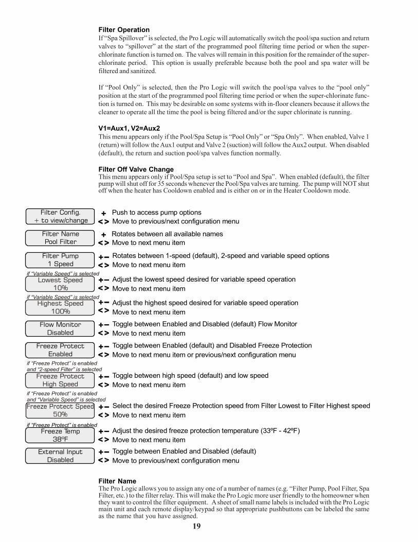
19
Filter OperationIf “Spa Spillover” is selected, the Pro Logic will automatically switch the pool/spa suction and returnvalves to “spillover” at the start of the programmed pool filtering time period or when the super-chlorinate function is turned on. The valves will remain in this position for the remainder of the super-chlorinate period. This option is usually preferable because both the pool and spa water will befiltered and sanitized.
If “Pool Only” is selected, then the Pro Logic will switch the pool/spa valves to the “pool only”position at the start of the programmed pool filtering time period or when the super-chlorinate func-tion is turned on. This may be desirable on some systems with in-floor cleaners because it allows thecleaner to operate all the time the pool is being filtered and/or the super chlorinate is running.
V1=Aux1, V2=Aux2This menu appears only if the Pool/Spa Setup is “Pool Only” or “Spa Only”. When enabled, Valve 1(return) will follow the Aux1 output and Valve 2 (suction) will follow the Aux2 output. When disabled(default), the return and suction pool/spa valves function normally.
Filter Off Valve ChangeThis menu appears only if Pool/Spa setup is set to “Pool and Spa”. When enabled (default), the filterpump will shut off for 35 seconds whenever the Pool/Spa valves are turning. The pump will NOT shutoff when the heater has Cooldown enabled and is either on or in the Heater Cooldown mode.
Filter Config.+ to view/change
Filter NamePool Filter
Filter Pump 1 Speed
Freeze Protect Enabled
Flow MonitorDisabled
Lowest Speed10%
Highest Speed100%
Push to access pump options
Rotates between all available names
Rotates between 1-speed (default), 2-speed and variable speed options
Toggle between Enabled (default) and Disabled Freeze Protection
Toggle between Enabled and Disabled Flow Monitor (default)
Adjust the lowest speed desired for variable speed operation
Adjust the highest speed desired for variable speed operation
Move to next menu item
Move to previous/next configuration menu
Move to next menu item
Move to next menu item or previous/next configuration menu
Move to next menu item
Move to next menu item
Move to next menu item
if “Variable Speed” is selected
if “Variable Speed” is selected
Freeze Temp38ºF
Freeze ProtectHigh Speed
Adjust the desired freeze protection temperature (33ºF - 42ºF)
Toggle between high speed (default) and low speed
Select the desired Freeze Protection speed from Filter Lowest to Filter Highest speed
Move to next menu item
Move to next menu item
Move to next menu itemif “Freeze Protect” is enabled
if “Freeze Protect” is enabledand “2-speed Filter” is selected
if “Freeze Protect” is enabledand “Variable Speed” is selected
External InputDisabled
Toggle between Enabled and Disabled (default)Move to previous/next configuration menu
Filter NameThe Pro Logic allows you to assign any one of a number of names (e.g. “Filter Pump, Pool Filter, SpaFilter, etc.) to the filter relay. This will make the Pro Logic more user friendly to the homeowner whenthey want to control the filter equipment. A sheet of small name labels is included with the Pro Logicmain unit and each remote display/keypad so that appropriate pushbuttons can be labeled the sameas the name that you have assigned.
28
Aux1 GroupThe Aux1 Group function allows the user to perform multiple tasks with a single push of the “Aux1”button. When setting up a Group function, refer to page 15 for specific programming information.There are two Group menus; the first menu determines how the group command will be initiated(Manual On/Off, Countdown Timer, or Timeclock) and the second menu selects the desired functionsand their respective control parameters.
When activating Group functions, be aware that the most recent Group function that is initiated willoverride any previous Group function.
Aux1 External Input InterlockWhen Aux1 External Input Interlock is enabled, the Aux1 output will be forced off when the externalinput is active. This will have precedence over freeze protection. Aux1 External Input Interlock is notavailable for solar, low speed filter pump, dimmer, group, super chlorinate, or pH dispense functions.
Aux1 Freeze ProtectionThis function protects the pool, plumbing, and equipment against freeze damage. If Freeze Protectionis enabled and the AIR temperature sensor falls below the selected freeze protection temperature, thePro Logic will turn on the aux relay to circulate the water. IMPORTANT: this only enables operationof the AUX output during freeze--see the “Filter Pump Config.” menu to enable freeze protection forthe main circulation system. Freeze Protection is not available for low speed filter pump, dimmer,group, super chlorinate or pH dispense functions.
Aux1 Pump SpeedThis is the speed of the filter pump when the Aux1 output is on. The default selection is “SettingsMenu”. This is the speed of the pump that has been selected in the Settings Menu for normal filteroperation. If an alternate speed is desired when the Aux1 output is on, push “+” or “-” and select from“Lowest” to “Highest” in 5% increments.
PL-PS-8-V models only: Aux3 - Aux7 onlyPL-PS-16-V models only: Aux7 - Aux14 only
Aux7 RelayStandard
Toggle between Standard (default) and ColorLogic (must be detected) Move to next menu item or previous/next configuration menu
Aux7 Config.+ to view/change
Aux7 FunctionGroup
Aux7 GroupFilter: Unaffected
Aux7 GroupTimer: None(Manual)
Push to access Virtual Aux options
Rotates between Super Chlorinate, Group and Manual On/Off
Options available depend on the function that is selected
Rotates between Manual On/Off (default),Countdown Timer and Timeclock
Move to previous/next configuration menu
Move to next menu item
Move to previous/next menu item or next configuration menu
Move to next configuration menu item
Aux7 NameCleaner
Rotates between all available names Move to next menu item
For more information on the Group function, refer to page 15. If neither Super Chlorinate, ColorLogic or a Groupcan be assigned to a Virtual Aux button, the following will be displayed:
No VirtualFunctions Available

20
Filter PumpFor 2-speed pumps: When a 2-speed pump is configured, one of the AUX relays must also beconfigured to control the low speed motor winding on the pump. Refer to the appropriate sections inthe Installation manual for specific information regarding the control logic for 2-speed and variablespeed pump operation.
For the Hayward variable speed pump: The Filter relay is used to supply input power to the pump.The relay will be on when the filter pump output is on. When the filter pump output is off, the relay willbe off. On , off and speed is controlled by commands sent to the pump.
Lowest SpeedThis is the lowest speed that the variable speed pump is allowed to run at. It is used as the lower limitin the Low Speed Settings Menu. Set lowest speed from 10% (default) to 50%.
Highest SpeedThis is the highest speed that the variable speed pump is allowed to run at. It is used as the upper limitin the High Speed Settings Menu. Also, this is the speed that the pump will run at during the first 3minutes of operation anytime the pump has been off for more than 30 seconds. Set highest speed from20% to 100% (default).
Flow MonitorThis feature will help protect the filter pump from damage due to no flow. When used with a Haywardflow switch, the Pro Logic monitors the state of water flow when the filter pump is on. If no flow isdetected for more than 15 minutes, the Pro Logic will shut down the pool pump and the “CheckSystem” LED will indicate an error. The error will be cleared the next time the pump is turned on.
Freeze ProtectionFreeze protection is used to protect the pool and plumbed equipment against freeze damage. If freezeprotection is enabled and the AIR temperature sensor falls below the freeze threshold (see below), thePro Logic will turn on the filter pump to circulate the water. If “Pool and Spa” is selected in the Pool/Spa sub-menu (see page 18), the valves will also alternate between the pool and spa every 30 minutesand the filter pump will turn off while the valves are turning. The chlorinator will not operate if freezeprotection is the only reason the pump is running.
Freeze Protection SpeedThis menu only appears if freeze protection is enabled and the pump is configured for 2-speed orvariable speed pump operation. If the pump turns on due to freeze protection only, the pump will runat this speed.
2-Speed pumps: Select high (default) or low speed operation.
Variable Speed pumps: Select the desired speed (from Filter Lowest to Filter Highest speed).
Freeze Protection TemperatureSelect the temperature to be used for freeze protection. Temperature is adjustable from 33ºF-42ºF (1ºC-6ºC). 38ºF (3ºC) is default. This threshold will be used for all outputs that have freeze protectionenabled.
External Input InterlockWhen enabled, the filter pump will be forced off when the external input is active. Note that freezeprotection will have precedence over this feature.
27
more user friendly to the homeowner when they want to turn various aux equipment on or off orprogram the timeclocks. A sheet of small name labels is included with the Pro Logic main unit and eachremote display/keypad so that the “Aux” pushbutton can be labeled the same as the name that youhave assigned. At this time it is also a good idea to make sure that the relay in the control box is alsolabeled (hand written) with the same name as a help to technicians who may service this system at alater date.
Aux1 FunctionManual On/Off (default)—the aux relay will alternate between turning on and off when the aux buttonis pressed. There is no automatic control logic.
Countdown Timer – the aux relay will turn on when the AUX button is pressed and then will turn offautomatically after a programmed time (see Timers Menu in the Operations Manual). The AUX buttoncan also be used to turn the output off.
Low Speed of a 2-speed Filter Pump – the Pro Logic will operate the aux relay whenever the low speedoperation of the filter pump is required. It is very important that the “2-speed” filter pump option beselected under the “Filter Config.” Menu for proper operation.
Timeclock – the aux relay will turn-on and turn-off at the times set for the aux timeclock in the TimersMenu (see Operations Manual). The AUX button can also be used to turn the output on and off.
Solar – the aux relay operates a solar booster pump which will turn on when the filter pump is runningand solar heat is available and the water is less than the desired temperature setting. It is important tonote that “Solar” must be enabled in the “Solar Config.” menu for proper operation to occur.
Low Speed of a 2-Speed Spa Filter Pump – the Pro Logic will turn on the aux relay whenever the lowspeed operation of the Dual Equipment Spa filter pump is required. “Pool and Spa-Dual” (located inPool/Spa Setup menu) and “2-Speed” (located in Spa Filter Config. menu) must be selected for properoperation.
Group – the aux relay operates when the Group function is initiated and shuts off when the Groupfunction is terminated. See Aux1 Group section for operation information for the Group function.
Super Chlorinate – The Super Chlorinate function can be assigned to any Aux, Lights or Valvebutton. This allows the user to simply hit a button to start a Super Chlorinate cycle, rather than usingthe Settings Menu. Note that only one button can me assigned to this function.
pH Dispense – When Chemistry Sensing is enabled and pH Reduction Control is NOT disabled, thePro Logic will turn on the Aux relay when there is a need to energize the pH dispensing device. The pHDispense function can be assigned to any Aux or the Lights output. Once programmed for pHDispense, the Aux button will have no function. Requires the use of the AQL-CHEM sensing kit.
Aux1 RelayThis feature allows the user to select either “Standard” (default), “Dimmer”, “ColorLogic” or “VSP”type relay for the Aux1 output. The optional AQL-DIM dimmer kit must be installed if “Dimmer” isdesired. The AQL-COLOR-MODHV ColorLogic Network Module must be installed if “ColorLogic” isdesired.
When “Dimmer” is selected, and the Aux1 output is manually turned on, the “+” and “-” buttonsadjust the level from 20% to 100% (default). The level is saved for the next time the aux1 output isturned from off to on.
If “ColorLogic” is selected (Network Module must be detected at startup for this option to appear),additional menus will prompt you for configuration information. Refer to the AQL-COLOR-MODHVmanual for details on how to configure an Aux output for use with Generation 3 or later ColorLogiclights.
If “VSP” is selected, the Aux relay is used to supply power to a Hayward Variable Speed Pump (VSP).The relay will be on when the Aux output is on and off when the output is off. On, off and speed arecontrolled by commands sent to the VSP. Note: Up to 6 Lights/Aux outputs can be configured as VSPrelays.
Aux1 InterlockIf “Enabled”, this feature will override the function (Manual On/Off, Countdown Timer, Timeclock),selected above and turn the aux1 off when: filter pump is off, first 3 minutes of filter pump operation(allows the pump to prime and get water flowing), when the pool/spa suction return valves are in anyposition other than “pool only”, or for the first 3 minutes after solar turns on (allows air in the solarpanels to be purged). Interlock is not available for solar, low speed filter pump, dimmer, group, superchlorinate or pH dispense functions.

21
Select the desired Freeze Protection speed from Spa Filter Lowest to Highest speed Move to next menu item
if “Freeze Protect” is enabledand “Variable Speed” is selected
Spa Filter Pump 1 Speed
Freeze Protect Enabled
Freeze ProtectHigh Speed
Lowest Speed10%
Highest Speed100%
Rotates between 1-speed (default), 2-speed and variable speed options
Toggle between Enabled (default) and Disabled Freeze Protection
Toggle between high speed (default) and low speed
Adjust the lowest speed desired for variable speed operation
Adjust the highest speed desired for variable speed operation
Move to next menu item
Move to next menu item or previous/next configuration menu
Move to next menu item
Move to next menu item
Move to next menu item
if “Freeze Protect” is enabledand “2-speed Filter” is selected
if “Variable Speed” is selected
if “Variable Speed” is selected
Spa Filter Config.+ to view/change
Push to access Spa Filter optionsMove to previous/next configuration menu item
if “Pool & Spa Dual” is selected
External InputDisabled
Toggle between Enabled and Disabled (default)Move to previous/next configuration menu
Spa Filter PumpFor 2-speed pumps: When a 2-speed pump is configured, one of the AUX relays must also beconfigured to control the low speed motor winding on the pump. Refer to the appropriate sections inthe Installation manual for specific information regarding the control logic for 2-speed and variablespeed pump operation.
For the Hayward variable speed pump: The Spa Filter (Aux1) relay is used to supply input power tothe pump. The relay will be on when the filter pump output is on. When the filter pump output is off,the relay will be off. On , Off and speed is controlled by commands sent to the pump.
Lowest SpeedThis is the lowest speed that the variable speed pump is allowed to run at. It is used as the lower limitin the Spa Low Speed Settings Menu. Set lowest speed from 10% (default) to 50%.
Highest SpeedThis is the highest speed that the variable speed pump is allowed to run at. It is used as the upper limitin the Spa High Speed Settings Menu. Also, this is the speed that the pump will run during the first 3minutes of operation anytime the pump has been off for more than 30 seconds. Set highest speed from20% to 100% (default).
Freeze ProtectionFreeze protection is used to protect the spa and plumbed equipment against freeze damage. If freezeprotection is enabled and the AIR temperature sensor falls below the freeze threshold (selectable inFilter Configuration Menu - page 20), the Pro Logic will turn on the spa filter pump to circulate thewater.
Freeze Protection SpeedThis menu only appears if freeze protection is enabled and the pump is configured for 2-speed orvariable speed pump operation. If the pump turns on due to freeze protection only, the pump will runat this speed.
2-Speed pumps: Select high (default) or low speed operation.
Variable Speed pumps: Select the desired speed (from Filter Lowest to Filter Highest speed).
External InputWhen enabled, the filter pump will be forced off when the external input is active. Note that freezeprotection will have precedence over this feature.
26
Lights External Input InterlockWhen Lights External Input Interlock is enabled, the lights output will be forced off when the externalinput is active. This will have precedence over freeze protection. Lights External Input Interlock is notavailable for solar, low speed filter pump, dimmer, group, super chlorinate, or pH dispense functions.
Lights Freeze ProtectionThis function helps protect equipment that is wired to the lights relay against freeze damage. If FreezeProtection is enabled and the AIR temperature sensor falls below the selected freeze temperaturethreshold, the Pro Logic will energize the lights relay. IMPORTANT: this only enables operation ofthe lights relay during freeze--see the “Filter Pump Config.” menu to enable freeze protection for themain circulation system. Freeze Protection is not available for low speed filter pump, dimmer, group,super chlorinate or pH dispense functions.
Lights Pump SpeedThis is the speed of the filter pump when the Lights output is on. The default selection is “SettingsMenu”. This is the speed of the pump that has been selected in the Settings Menu for normal filteroperation. If an alternate speed is desired when the Lights output is on, push “+” or “-” and selectfrom “Filter Lowest” to “Filter Highest” in 5% increments.
NOTE: The configuration parameters for all Aux outputs are the same as shown below for Aux1. PS-4: Aux1 and Aux2. PS-8:Aux1 through Aux6. PS-16: Aux1 through Aux14. Also note that for the PS-16, Valves7, 8, 9 and 10 are turned On/Off with thecontrol function selected for Aux7, 8, 9, and 10, respectively.
Aux1 Pump SpdSettings Menu
Select Settings Menu (default) or desired pump speed (Filter Lowest to Highest)Move to previous/next configuration menu
if filter pump is set to variable speedand the relay type is set to standard
Aux1 Config.+ to view/change
Aux1 FunctionManual On/Off
Aux1 GroupFilter: Unaffected
Aux1 GroupTimer: None(Manual)
Aux1 NameCleaner
Aux1 RelayStandard
Push to access Aux options
Options available depend on the function that is selected
Rotates between Manual On/Off (default),Countdown Timer and Timeclock
Rotates between all available names
Toggle between Standard (default), Dimmer, ColorLogic and VSP
Move to previous/next configuration menu
Move to previous/next menu item or next configuration menu
Move to next configuration menu item
Move to next menu item
Move to next menu item or previous/next configuration menu
Aux1 InterlockDisable
Aux1 FreezeDisable
Toggle between Enabled and Disabled (default) Aux1 Interlock
Toggle between Enabled and Disabled Aux1 Freeze(default)
Move to next menu item
Move to previous/next configuration menu
for all functions except solar, dimmer relay,super chlorinate
for all functions except solar, dimmer relay,super chlorinate
low speed, group and pH dispense
low speed, group and pH dispense
for all functions except dimmer relay, super chlorinatelow speed, group and ph dispense
for group function only
for group function only
for manual on/off, countdowntimer and timeclock functions
Move to next menu item
Rotates between Manual On/Off (default), Countdown Timer, Low Speed- Filter,Timeclock, Solar, Low Speed-Spa Filter, Group, Super Chlorinate, and pH Dispense
Aux1 Ext InputDisabled
Toggle between Enabled and Disabled (default)Move to previous/next configuration menu
! WARNING: Do not use the Pro Logic to control an automatic pool cover. Swimmersmay become entrapped underneath the cover.
NOTE: If “Pool and Spa-Dual” is selected, Aux1 is dedicated to use as the spa filter. Its Name is set to Spa Filter, the Functionis set to Timeclock and Interlock is set to Disabled. These can’t be changed.
Aux1 NameThe Pro Logic allows you to assign any one of a number of names (e.g. “Cleaner Pump, Waterfall,Gazebo Light, etc.) to each of the aux outputs control function. This will make the Pro Logic much

22
NOTE: Heater1 and Heater2 configuration are identical. If Heater2 is enabled then Valve4 will automatically be disabled dueto the fact that they use the same output relay and only 1 function can be assigned to that relay.
Heater1 Config.+ to view/change
Heater1 Disable
Heater1 Cooldown Disabled
Heater1 Extend Disabled
No
Push to access heater options
Toggle between Enabled and Disabled (default) Heater 1
Toggle between Enabled and Disabled (default) Heater 1 Cooldown
Toggle between Enabled and Disabled (default) Heater 1 Extend
Toggle between Enabled and Disabled (default)
Move to previous/next configuration menu
Move to next menu item or previous/next configuration menu
Move to next menu item
Move to previous/next configuration menu
Move to previous/next configuration menu
if “Heater1” is enabled
if “Heater1” is enabled
if “Heater1” is enabled
display for Heater2 if "Heater2" is enabled
Heater1 NameGas Heater
Rotates between all available names Move to next menu item
Allow Low Speed
Minimum Speed
Disabled
50%
Toggle between Enabled and Disabled (default)
Select the desired minimum filter pump speed for Heater 1 (Filter Lowest to Highest)
Move to
Move to
next menu item or previous/next configuration menu
next menu item or previous/next configuration menu
if “Heater1” is enabled and
if “Heater1” is enabled and
2-speed filter pump is selected
variable speed filter pump is selected
Heater1If the heater is “Enabled”, the heater relay will turn on when the water temperature is less than thedesired temperature setting and the filter pump is running. The desired temperature is in the “SettingsMenu”. If applicable, the homeowner will be prompted to enter separate “pool” and “spa” settings.Depending on the position of the pool/spa suction valves, the proper temperature setting will beused.
Heater NameThe Pro Logic allows you to assign any one of a number of names (e.g. “Gas Heater, Heat Pump, etc.)to each of the heater control functions. This will make the Pro Logic much more user friendly to thehomeowner when they want to turn various heaters on or off or set temperatures. A sheet of smallname labels is included with the Pro Logic main unit and each remote display/keypad so that appro-priate pushbuttons can be labeled the same as the name that you have assigned.
Heater CooldownThis feature ensures that the heater cools down before water circulation is stopped. When enabled,the Pro Logic will continue to run the filter pump for 5 minutes after the heater turns off. During thisperiod the filter pump LED will flash and also a “Heater Cooldown, X:XX remaining” message willscroll on the display.
When the filter pump is running and the heater is on: Pressing the “Filter” button once will cause theheater to turn off, but the filter pump will continue to run for heater cooldown (filter LED flashing andmessage on display). Pushing the filter button a second time will override the heater cooldownoperation and turn the filter pump off.
For a Pool/Spa Setup selection of “Pool Only”, “Spa Only” or “Pool and Spa-Std”, Heater1 and/orHeater2 cooldown affect the filter pump. For “Pool and Spa-Dual”, Heater1 is associated with the spafilter and Heater2 with the pool filter.
Heater ExtendIf “Enabled”, the filter extend logic keeps the filter pump running beyond the normal turn-off time untilthe pool (or spa) is heated up to the desired temperature setting (see Settings Menu). Heater extendwill NOT cause the filter pump to turn on, it will only delay the turn off time when the heater isoperating.
25
be disabled. If no pool lights are used, the lights relay can be used to control other pool devices thatmay require these options. The function of each option is shown below.
Manual On/Off—the lights relay will alternate between turning on and off when the LIGHTS button ispressed. There is no automatic control logic.
Countdown Timer—the lights relay will turn on when the LIGHTS button is pressed. The lights relaywill turn off automatically after a programmed time (see Timers Menu). The LIGHTS button can alsobe used to turn the output off.
Low Speed of a 2-speed Filter Pump – the Pro Logic will turn on the lights relay whenever the lowspeed operation of the filter pump is required. It is very important that the “2-speed” filter pumpoption be selected under the “Filter Config.” Menu for proper operation.
Timeclock – the lights relay will turn-on and turn-off at the times set for the lights timeclock in theSettings Menu (see Settings Menu). The LIGHTS button can also be used to turn the output on andoff.
Solar – the lights relay can operate a solar booster pump which will turn on when the filter pump isrunning and solar heat is available and the water is less than the desired temperature setting. Notethat “Solar” must be enabled in the “Solar Config.” menu for proper operation to occur.
Low Speed of a 2-Speed Spa Filter Pump – the Pro Logic will turn on the lights relay whenever the lowspeed operation of the Dual Equipment Spa filter pump is required. “Pool and Spa-Dual” (located inPool/Spa Setup menu) and “2-Speed” (located in Spa Filter Config. menu) must be selected for properoperation.
Group – the lights relay operates when the Group function is initiated and shuts off when the Groupfunction is terminated. See Lights Group section for operation information for the Group function.
Super Chlorinate – The Super Chlorinate function can be assigned to any Aux, Lights or Valvebutton. This allows the user to simply hit a button to start a Super Chlorinate cycle, rather than usingthe Settings Menu. Note that only one button can me assigned to this function.
pH Dispense –When Chemistry Sensing is enabled and pH Reduction Control is NOT disabled, thePro Logic will turn on the Lights relay when there is a need to energize the pH dispensing device. ThepH Dispense function can be assigned to any Aux or the Lights output. Once programmed for pHDispense, the Lights button will have no function. Requires the use of the AQL-CHEM sensing kit.
Lights RelayThis feature allows the user to select either “Standard” (default), “Dimmer” or “VSP” type relay for theLights output. The optional AQL-DIM dimmer kit must be installed if “Dimmer” is desired.
When “Dimmer” is selected, and the Lights output is manually turned on, the “+” and “-” buttonsadjust the level from 20% to 100% (default). The level is saved for the next time the lights are turnedfrom off to on.
If “VSP” is selected, the Lights relay is used to supply power to a Hayward Variable Speed Pump(VSP). The relay will be on when the Lights output is on and off when the output is off. On, off andspeed are controlled by commands sent to the VSP. Note: Up to 6 Lights/Aux outputs can beconfigured as VSP relays.
Lights InterlockIf enabled, this feature will override the function (Manual On/Off, Countdown Timer, Timeclock)selected above and turn the lights relay off when: filter pump is off, first 3 minutes of filter pumpoperation (allows the pump to prime and get water flowing), when the pool/spa suction return valvesare in any position other than “pool only”, or for the first 3 minutes after solar turns on (allows air inthe solar panels to be purged). Interlock is not available for solar, low speed filter pump, dimmer,group, super chlorinate, or pH dispense functions.
Lights GroupThe Lights Group function allows the user to perform multiple tasks with a single push of the “Lights”button. When setting up a Group function, refer to page 15 for specific programming information.There are two Group menus; the first menu determines how the group command will be initiated(Manual On/Off, Countdown Timer, or Timeclock) and the second menu selects the desired functionsand their respective control parameters.
When activating Group functions, be aware that the most recent Group function that is initiated willoverride any previous Group function.

23
For a Pool/Spa Setup selection of “Pool Only”, “Spa Only” or “Pool and Spa-Std”, Heater1 and/orHeater2 will keep the filter pump running. For “Pool and Spa-Dual”, Heater1 will keep the spa filterrunning and Heater2 will keep the pool filter running.
Allow Low SpeedThis menu only appears if the filter is configured for 2-speed operation. During default operation,high speed mode is used whenever the heater is on. If Allow Low Speed is enabled, low speed will beallowed even if the heater is on.
Minimum SpeedThis menu only appears if the filter is configured for variable speed operation. This is the minimumspeed the pump will run at when the heater is on. The selection is from Filter Lowest to Filter Highestspeed.
Heater2 is HeatpumpThis menu appears in the Heater2 configuration menu if Heater2 is enabled. If set to “Yes”, Heater2will only be allowed to be on if the Air Temperature is > 50°F. Also, two new menus, Spa Heater2Priority and Pool Heater2 Priority, will appear in the Settings Menu. Refer to the Settings Menu formore information on these new menus.
Solar Config.+ to view/change
SolarDisabled
Solar-Extend Disabled
Solar PriorityDisabled
Push to access solar options
Toggle between Enabled and Disabled (default) Solar
Toggle between Enabled and Disabled (default) Solar Extend
Toggle between Enabled and Disabled (default) Solar Priority
Move to previous/next configuration menu
Move to next menu item or previous/next configuration menu
Move to next menu item
Move to next menu item
if “Solar” is enabled
if “Solar” is enabled
Allow Low Speed Disabled
Toggle between Enabled and Disabled (default) Move to next menu item or previous/next configuration menu
if “Solar” is enabled and“2-speed Filter” is selected
SolarThe Solar configuration menu will NOT appear if “Pool and Spa - Dual” has been selected in the Pool/Spa setup menu. If the solar control logic is “Enabled”, several additional steps must be taken toensure proper operation of the solar heating system. If the solar is operated by a valve, then a valve(Valve3 or Valve4) output must be setup for solar logic (page 29). If the solar is operated by a pump,then one of the AUX relays must be set up for solar logic (page 27). Also, the “solar” temperaturesensor must be installed. This sensor is typically mounted near the collector array and is used tosense whether sufficient solar heat is available.
If solar is “Enabled”, the valve or solar pump relay will turn on when the water temperature is less thanthe desired temperature setting AND the solar sensor is hotter than the water by at least 8ºF. Thedesired temperature is in the “Settings Menu”. If applicable, the homeowner will be prompted to enterseparate pool and spa desired temperature settings. Depending on the position of the pool/spasuction valve, the proper temperature setting will be used.
Solar ExtendIf “Enabled”, the filter extend logic keeps the filter pump running beyond the normal turn-off time ifsolar heat is still available. When solar heat is no longer available, both the solar valve/pump and filterpump will turn off simultaneously. Solar extend will NOT cause the filter pump to turn on, it will onlydelay the turn off time when solar is operating.
Solar PriorityIf both “Solar Control” and “Heater Control” are enabled, the Solar Priority feature will keep theconventional heater off whenever solar heat is available. This provides the most cost effective way ofheating the pool. When solar heat is not available, the conventional heater will operate normally.
Allow Low SpeedThis menu only appears if the pool filter is configured for 2-speed operation. During default operation,high speed mode is used whenever the solar heater is on. If Allow Low Speed is enabled, low speedpump operation will be allowed during solar heating except for the first 3 minutes after solar heat turnson.
only if optional ColorLogic NetworkModule is detected at power up
ColorLogic Config.+ to view/change
Push to activate ColorLogic optionsMove to previous/next configuration menu
ColorLogic Config.This menu appears if the optional ColorLogic Network Module is installed and detected at power up.Refer to the AQL-COLOR-MODHV manual for detailed installation and operation instructions.
External InputActive Closed
Toggle between Open and Closed (default) Move to next menu item or previous/next configuration menu
External InputThe external input device can either be normally open or normally closed. In this menu, select the stateof the external input device when active. For example, if the switch is normally open and closes whenactive, set External Input to “Active Closed”.
NOTE: If an AQL-COLOR-MODHV ColorLogic Network Module is detected at startup, only the Lights Name menu will appearunder Lights Configuration. Refer to the AQL-COLOR-MODHV manual for more information.
Lights Config.+ to view/change
Lights FunctionManual On/Off
Lights NamePool Light
Lights RelayStandard
Push to access Lights options
Rotates between Manual On/Off (default), Countdown Timer, Low Speed- Filter,Timeclock, Solar, Low Speed-Spa Filter, Group, Super Chlorinate, and pH Dispense
Rotates between all available names
Toggle between Standard (default), Dimmer and VSP
Move to previous/next configuration menu
Move to next menu item
Move to next menu item or previous/next configuration menu
Move to next menu item or previous/next configuration menu
Lights InterlockDisable
Lights FreezeDisable
Toggle between Enabled and Disabled (default) Lights Interlock
Toggle between Enabled and Disabled (default) Lights Freeze
Move to next menu item
Move to previous/next configuration menu
for all functions except solar, dimmer relay, super chlorinatepH dispense, low speed, and group
for all functions except solar, dimmer relay, super chlorinatepH dispense, low speed, and group
f pH dispense, low speed, and groupor all functions except dimmer relay, super chlorinate
if filter pump is set to variable speedand the relay type is set to standard
for manual on/off, countdowntimer and timeclock functions
Lights GroupFilter: Unaffected
Lights GroupTimer: None(Manual)
Options available depend on the function that is selected
Rotates between Manual On/Off (default),Countdown Timer and Timeclock
Move to previous/next menu item or next configuration menu
Move to next menu itemfor group function only
for group function only
Lights Ext InputDisabled
Toggle between Enabled and Disabled (default)Move to previous/next configuration menu
Lights Pump SpdSettings Menu
Select Settings Menu (default) or desired pump speed (Filter Lowest to Highest)Move to previous/next configuration menu
Lights NameThe Pro Logic allows you to assign any one of a number of names (e.g. “Pool Light, Spa Light, DeckLight, etc.) to this control function. Note that other lights may be assigned to other Aux outputs. Thiswill make the Pro Logic much more user friendly to the homeowner when they want to turn variouslights on or off. A sheet of small name labels is included with the Pro Logic main unit and each remotedisplay/keypad so that the “Lights” pushbutton can be labeled the same as the name that you haveassigned. At this time it is also a good idea to make sure that the relay in the control box is also labeled(hand written) with the same name as a help to technicians who may service this system at a later date.
Lights FunctionAlthough designated as the “Lights” output, the function of the lights relay is similar to the Auxrelays. If pool lights are wired to the lights relay, some options including Solar function, Low Speedof a 2-Speed Filter Pump, Lights Interlock and Lights Freeze Protection are not applicable and should
24

22
NOTE: Heater1 and Heater2 configuration are identical. If Heater2 is enabled then Valve4 will automatically be disabled dueto the fact that they use the same output relay and only 1 function can be assigned to that relay.
Heater1 Config.+ to view/change
Heater1 Disable
Heater1 Cooldown Disabled
Heater1 Extend Disabled
No
Push to access heater options
Toggle between Enabled and Disabled (default) Heater 1
Toggle between Enabled and Disabled (default) Heater 1 Cooldown
Toggle between Enabled and Disabled (default) Heater 1 Extend
Toggle between Enabled and Disabled (default)
Move to previous/next configuration menu
Move to next menu item or previous/next configuration menu
Move to next menu item
Move to previous/next configuration menu
Move to previous/next configuration menu
if “Heater1” is enabled
if “Heater1” is enabled
if “Heater1” is enabled
display for Heater2 if "Heater2" is enabled
Heater1 NameGas Heater
Rotates between all available names Move to next menu item
Allow Low Speed
Minimum Speed
Disabled
50%
Toggle between Enabled and Disabled (default)
Select the desired minimum filter pump speed for Heater 1 (Filter Lowest to Highest)
Move to
Move to
next menu item or previous/next configuration menu
next menu item or previous/next configuration menu
if “Heater1” is enabled and
if “Heater1” is enabled and
2-speed filter pump is selected
variable speed filter pump is selected
Heater1If the heater is “Enabled”, the heater relay will turn on when the water temperature is less than thedesired temperature setting and the filter pump is running. The desired temperature is in the “SettingsMenu”. If applicable, the homeowner will be prompted to enter separate “pool” and “spa” settings.Depending on the position of the pool/spa suction valves, the proper temperature setting will beused.
Heater NameThe Pro Logic allows you to assign any one of a number of names (e.g. “Gas Heater, Heat Pump, etc.)to each of the heater control functions. This will make the Pro Logic much more user friendly to thehomeowner when they want to turn various heaters on or off or set temperatures. A sheet of smallname labels is included with the Pro Logic main unit and each remote display/keypad so that appro-priate pushbuttons can be labeled the same as the name that you have assigned.
Heater CooldownThis feature ensures that the heater cools down before water circulation is stopped. When enabled,the Pro Logic will continue to run the filter pump for 5 minutes after the heater turns off. During thisperiod the filter pump LED will flash and also a “Heater Cooldown, X:XX remaining” message willscroll on the display.
When the filter pump is running and the heater is on: Pressing the “Filter” button once will cause theheater to turn off, but the filter pump will continue to run for heater cooldown (filter LED flashing andmessage on display). Pushing the filter button a second time will override the heater cooldownoperation and turn the filter pump off.
For a Pool/Spa Setup selection of “Pool Only”, “Spa Only” or “Pool and Spa-Std”, Heater1 and/orHeater2 cooldown affect the filter pump. For “Pool and Spa-Dual”, Heater1 is associated with the spafilter and Heater2 with the pool filter.
Heater ExtendIf “Enabled”, the filter extend logic keeps the filter pump running beyond the normal turn-off time untilthe pool (or spa) is heated up to the desired temperature setting (see Settings Menu). Heater extendwill NOT cause the filter pump to turn on, it will only delay the turn off time when the heater isoperating.
25
be disabled. If no pool lights are used, the lights relay can be used to control other pool devices thatmay require these options. The function of each option is shown below.
Manual On/Off—the lights relay will alternate between turning on and off when the LIGHTS button ispressed. There is no automatic control logic.
Countdown Timer—the lights relay will turn on when the LIGHTS button is pressed. The lights relaywill turn off automatically after a programmed time (see Timers Menu). The LIGHTS button can alsobe used to turn the output off.
Low Speed of a 2-speed Filter Pump – the Pro Logic will turn on the lights relay whenever the lowspeed operation of the filter pump is required. It is very important that the “2-speed” filter pumpoption be selected under the “Filter Config.” Menu for proper operation.
Timeclock – the lights relay will turn-on and turn-off at the times set for the lights timeclock in theSettings Menu (see Settings Menu). The LIGHTS button can also be used to turn the output on andoff.
Solar – the lights relay can operate a solar booster pump which will turn on when the filter pump isrunning and solar heat is available and the water is less than the desired temperature setting. Notethat “Solar” must be enabled in the “Solar Config.” menu for proper operation to occur.
Low Speed of a 2-Speed Spa Filter Pump – the Pro Logic will turn on the lights relay whenever the lowspeed operation of the Dual Equipment Spa filter pump is required. “Pool and Spa-Dual” (located inPool/Spa Setup menu) and “2-Speed” (located in Spa Filter Config. menu) must be selected for properoperation.
Group – the lights relay operates when the Group function is initiated and shuts off when the Groupfunction is terminated. See Lights Group section for operation information for the Group function.
Super Chlorinate – The Super Chlorinate function can be assigned to any Aux, Lights or Valvebutton. This allows the user to simply hit a button to start a Super Chlorinate cycle, rather than usingthe Settings Menu. Note that only one button can me assigned to this function.
pH Dispense –When Chemistry Sensing is enabled and pH Reduction Control is NOT disabled, thePro Logic will turn on the Lights relay when there is a need to energize the pH dispensing device. ThepH Dispense function can be assigned to any Aux or the Lights output. Once programmed for pHDispense, the Lights button will have no function. Requires the use of the AQL-CHEM sensing kit.
Lights RelayThis feature allows the user to select either “Standard” (default), “Dimmer” or “VSP” type relay for theLights output. The optional AQL-DIM dimmer kit must be installed if “Dimmer” is desired.
When “Dimmer” is selected, and the Lights output is manually turned on, the “+” and “-” buttonsadjust the level from 20% to 100% (default). The level is saved for the next time the lights are turnedfrom off to on.
If “VSP” is selected, the Lights relay is used to supply power to a Hayward Variable Speed Pump(VSP). The relay will be on when the Lights output is on and off when the output is off. On, off andspeed are controlled by commands sent to the VSP. Note: Up to 6 Lights/Aux outputs can beconfigured as VSP relays.
Lights InterlockIf enabled, this feature will override the function (Manual On/Off, Countdown Timer, Timeclock)selected above and turn the lights relay off when: filter pump is off, first 3 minutes of filter pumpoperation (allows the pump to prime and get water flowing), when the pool/spa suction return valvesare in any position other than “pool only”, or for the first 3 minutes after solar turns on (allows air inthe solar panels to be purged). Interlock is not available for solar, low speed filter pump, dimmer,group, super chlorinate, or pH dispense functions.
Lights GroupThe Lights Group function allows the user to perform multiple tasks with a single push of the “Lights”button. When setting up a Group function, refer to page 15 for specific programming information.There are two Group menus; the first menu determines how the group command will be initiated(Manual On/Off, Countdown Timer, or Timeclock) and the second menu selects the desired functionsand their respective control parameters.
When activating Group functions, be aware that the most recent Group function that is initiated willoverride any previous Group function.

21
Select the desired Freeze Protection speed from Spa Filter Lowest to Highest speed Move to next menu item
if “Freeze Protect” is enabledand “Variable Speed” is selected
Spa Filter Pump 1 Speed
Freeze Protect Enabled
Freeze ProtectHigh Speed
Lowest Speed10%
Highest Speed100%
Rotates between 1-speed (default), 2-speed and variable speed options
Toggle between Enabled (default) and Disabled Freeze Protection
Toggle between high speed (default) and low speed
Adjust the lowest speed desired for variable speed operation
Adjust the highest speed desired for variable speed operation
Move to next menu item
Move to next menu item or previous/next configuration menu
Move to next menu item
Move to next menu item
Move to next menu item
if “Freeze Protect” is enabledand “2-speed Filter” is selected
if “Variable Speed” is selected
if “Variable Speed” is selected
Spa Filter Config.+ to view/change
Push to access Spa Filter optionsMove to previous/next configuration menu item
if “Pool & Spa Dual” is selected
External InputDisabled
Toggle between Enabled and Disabled (default)Move to previous/next configuration menu
Spa Filter PumpFor 2-speed pumps: When a 2-speed pump is configured, one of the AUX relays must also beconfigured to control the low speed motor winding on the pump. Refer to the appropriate sections inthe Installation manual for specific information regarding the control logic for 2-speed and variablespeed pump operation.
For the Hayward variable speed pump: The Spa Filter (Aux1) relay is used to supply input power tothe pump. The relay will be on when the filter pump output is on. When the filter pump output is off,the relay will be off. On , Off and speed is controlled by commands sent to the pump.
Lowest SpeedThis is the lowest speed that the variable speed pump is allowed to run at. It is used as the lower limitin the Spa Low Speed Settings Menu. Set lowest speed from 10% (default) to 50%.
Highest SpeedThis is the highest speed that the variable speed pump is allowed to run at. It is used as the upper limitin the Spa High Speed Settings Menu. Also, this is the speed that the pump will run during the first 3minutes of operation anytime the pump has been off for more than 30 seconds. Set highest speed from20% to 100% (default).
Freeze ProtectionFreeze protection is used to protect the spa and plumbed equipment against freeze damage. If freezeprotection is enabled and the AIR temperature sensor falls below the freeze threshold (selectable inFilter Configuration Menu - page 20), the Pro Logic will turn on the spa filter pump to circulate thewater.
Freeze Protection SpeedThis menu only appears if freeze protection is enabled and the pump is configured for 2-speed orvariable speed pump operation. If the pump turns on due to freeze protection only, the pump will runat this speed.
2-Speed pumps: Select high (default) or low speed operation.
Variable Speed pumps: Select the desired speed (from Filter Lowest to Filter Highest speed).
External InputWhen enabled, the filter pump will be forced off when the external input is active. Note that freezeprotection will have precedence over this feature.
26
Lights External Input InterlockWhen Lights External Input Interlock is enabled, the lights output will be forced off when the externalinput is active. This will have precedence over freeze protection. Lights External Input Interlock is notavailable for solar, low speed filter pump, dimmer, group, super chlorinate, or pH dispense functions.
Lights Freeze ProtectionThis function helps protect equipment that is wired to the lights relay against freeze damage. If FreezeProtection is enabled and the AIR temperature sensor falls below the selected freeze temperaturethreshold, the Pro Logic will energize the lights relay. IMPORTANT: this only enables operation ofthe lights relay during freeze--see the “Filter Pump Config.” menu to enable freeze protection for themain circulation system. Freeze Protection is not available for low speed filter pump, dimmer, group,super chlorinate or pH dispense functions.
Lights Pump SpeedThis is the speed of the filter pump when the Lights output is on. The default selection is “SettingsMenu”. This is the speed of the pump that has been selected in the Settings Menu for normal filteroperation. If an alternate speed is desired when the Lights output is on, push “+” or “-” and selectfrom “Filter Lowest” to “Filter Highest” in 5% increments.
NOTE: The configuration parameters for all Aux outputs are the same as shown below for Aux1. PS-4: Aux1 and Aux2. PS-8:Aux1 through Aux6. PS-16: Aux1 through Aux14. Also note that for the PS-16, Valves7, 8, 9 and 10 are turned On/Off with thecontrol function selected for Aux7, 8, 9, and 10, respectively.
Aux1 Pump SpdSettings Menu
Select Settings Menu (default) or desired pump speed (Filter Lowest to Highest)Move to previous/next configuration menu
if filter pump is set to variable speedand the relay type is set to standard
Aux1 Config.+ to view/change
Aux1 FunctionManual On/Off
Aux1 GroupFilter: Unaffected
Aux1 GroupTimer: None(Manual)
Aux1 NameCleaner
Aux1 RelayStandard
Push to access Aux options
Options available depend on the function that is selected
Rotates between Manual On/Off (default),Countdown Timer and Timeclock
Rotates between all available names
Toggle between Standard (default), Dimmer, ColorLogic and VSP
Move to previous/next configuration menu
Move to previous/next menu item or next configuration menu
Move to next configuration menu item
Move to next menu item
Move to next menu item or previous/next configuration menu
Aux1 InterlockDisable
Aux1 FreezeDisable
Toggle between Enabled and Disabled (default) Aux1 Interlock
Toggle between Enabled and Disabled Aux1 Freeze(default)
Move to next menu item
Move to previous/next configuration menu
for all functions except solar, dimmer relay,super chlorinate
for all functions except solar, dimmer relay,super chlorinate
low speed, group and pH dispense
low speed, group and pH dispense
for all functions except dimmer relay, super chlorinatelow speed, group and ph dispense
for group function only
for group function only
for manual on/off, countdowntimer and timeclock functions
Move to next menu item
Rotates between Manual On/Off (default), Countdown Timer, Low Speed- Filter,Timeclock, Solar, Low Speed-Spa Filter, Group, Super Chlorinate, and pH Dispense
Aux1 Ext InputDisabled
Toggle between Enabled and Disabled (default)Move to previous/next configuration menu
! WARNING: Do not use the Pro Logic to control an automatic pool cover. Swimmersmay become entrapped underneath the cover.
NOTE: If “Pool and Spa-Dual” is selected, Aux1 is dedicated to use as the spa filter. Its Name is set to Spa Filter, the Functionis set to Timeclock and Interlock is set to Disabled. These can’t be changed.
Aux1 NameThe Pro Logic allows you to assign any one of a number of names (e.g. “Cleaner Pump, Waterfall,Gazebo Light, etc.) to each of the aux outputs control function. This will make the Pro Logic much

20
Filter PumpFor 2-speed pumps: When a 2-speed pump is configured, one of the AUX relays must also beconfigured to control the low speed motor winding on the pump. Refer to the appropriate sections inthe Installation manual for specific information regarding the control logic for 2-speed and variablespeed pump operation.
For the Hayward variable speed pump: The Filter relay is used to supply input power to the pump.The relay will be on when the filter pump output is on. When the filter pump output is off, the relay willbe off. On , off and speed is controlled by commands sent to the pump.
Lowest SpeedThis is the lowest speed that the variable speed pump is allowed to run at. It is used as the lower limitin the Low Speed Settings Menu. Set lowest speed from 10% (default) to 50%.
Highest SpeedThis is the highest speed that the variable speed pump is allowed to run at. It is used as the upper limitin the High Speed Settings Menu. Also, this is the speed that the pump will run at during the first 3minutes of operation anytime the pump has been off for more than 30 seconds. Set highest speed from20% to 100% (default).
Flow MonitorThis feature will help protect the filter pump from damage due to no flow. When used with a Haywardflow switch, the Pro Logic monitors the state of water flow when the filter pump is on. If no flow isdetected for more than 15 minutes, the Pro Logic will shut down the pool pump and the “CheckSystem” LED will indicate an error. The error will be cleared the next time the pump is turned on.
Freeze ProtectionFreeze protection is used to protect the pool and plumbed equipment against freeze damage. If freezeprotection is enabled and the AIR temperature sensor falls below the freeze threshold (see below), thePro Logic will turn on the filter pump to circulate the water. If “Pool and Spa” is selected in the Pool/Spa sub-menu (see page 18), the valves will also alternate between the pool and spa every 30 minutesand the filter pump will turn off while the valves are turning. The chlorinator will not operate if freezeprotection is the only reason the pump is running.
Freeze Protection SpeedThis menu only appears if freeze protection is enabled and the pump is configured for 2-speed orvariable speed pump operation. If the pump turns on due to freeze protection only, the pump will runat this speed.
2-Speed pumps: Select high (default) or low speed operation.
Variable Speed pumps: Select the desired speed (from Filter Lowest to Filter Highest speed).
Freeze Protection TemperatureSelect the temperature to be used for freeze protection. Temperature is adjustable from 33ºF-42ºF (1ºC-6ºC). 38ºF (3ºC) is default. This threshold will be used for all outputs that have freeze protectionenabled.
External Input InterlockWhen enabled, the filter pump will be forced off when the external input is active. Note that freezeprotection will have precedence over this feature.
27
more user friendly to the homeowner when they want to turn various aux equipment on or off orprogram the timeclocks. A sheet of small name labels is included with the Pro Logic main unit and eachremote display/keypad so that the “Aux” pushbutton can be labeled the same as the name that youhave assigned. At this time it is also a good idea to make sure that the relay in the control box is alsolabeled (hand written) with the same name as a help to technicians who may service this system at alater date.
Aux1 FunctionManual On/Off (default)—the aux relay will alternate between turning on and off when the aux buttonis pressed. There is no automatic control logic.
Countdown Timer – the aux relay will turn on when the AUX button is pressed and then will turn offautomatically after a programmed time (see Timers Menu in the Operations Manual). The AUX buttoncan also be used to turn the output off.
Low Speed of a 2-speed Filter Pump – the Pro Logic will operate the aux relay whenever the low speedoperation of the filter pump is required. It is very important that the “2-speed” filter pump option beselected under the “Filter Config.” Menu for proper operation.
Timeclock – the aux relay will turn-on and turn-off at the times set for the aux timeclock in the TimersMenu (see Operations Manual). The AUX button can also be used to turn the output on and off.
Solar – the aux relay operates a solar booster pump which will turn on when the filter pump is runningand solar heat is available and the water is less than the desired temperature setting. It is important tonote that “Solar” must be enabled in the “Solar Config.” menu for proper operation to occur.
Low Speed of a 2-Speed Spa Filter Pump – the Pro Logic will turn on the aux relay whenever the lowspeed operation of the Dual Equipment Spa filter pump is required. “Pool and Spa-Dual” (located inPool/Spa Setup menu) and “2-Speed” (located in Spa Filter Config. menu) must be selected for properoperation.
Group – the aux relay operates when the Group function is initiated and shuts off when the Groupfunction is terminated. See Aux1 Group section for operation information for the Group function.
Super Chlorinate – The Super Chlorinate function can be assigned to any Aux, Lights or Valvebutton. This allows the user to simply hit a button to start a Super Chlorinate cycle, rather than usingthe Settings Menu. Note that only one button can me assigned to this function.
pH Dispense – When Chemistry Sensing is enabled and pH Reduction Control is NOT disabled, thePro Logic will turn on the Aux relay when there is a need to energize the pH dispensing device. The pHDispense function can be assigned to any Aux or the Lights output. Once programmed for pHDispense, the Aux button will have no function. Requires the use of the AQL-CHEM sensing kit.
Aux1 RelayThis feature allows the user to select either “Standard” (default), “Dimmer”, “ColorLogic” or “VSP”type relay for the Aux1 output. The optional AQL-DIM dimmer kit must be installed if “Dimmer” isdesired. The AQL-COLOR-MODHV ColorLogic Network Module must be installed if “ColorLogic” isdesired.
When “Dimmer” is selected, and the Aux1 output is manually turned on, the “+” and “-” buttonsadjust the level from 20% to 100% (default). The level is saved for the next time the aux1 output isturned from off to on.
If “ColorLogic” is selected (Network Module must be detected at startup for this option to appear),additional menus will prompt you for configuration information. Refer to the AQL-COLOR-MODHVmanual for details on how to configure an Aux output for use with Generation 3 or later ColorLogiclights.
If “VSP” is selected, the Aux relay is used to supply power to a Hayward Variable Speed Pump (VSP).The relay will be on when the Aux output is on and off when the output is off. On, off and speed arecontrolled by commands sent to the VSP. Note: Up to 6 Lights/Aux outputs can be configured as VSPrelays.
Aux1 InterlockIf “Enabled”, this feature will override the function (Manual On/Off, Countdown Timer, Timeclock),selected above and turn the aux1 off when: filter pump is off, first 3 minutes of filter pump operation(allows the pump to prime and get water flowing), when the pool/spa suction return valves are in anyposition other than “pool only”, or for the first 3 minutes after solar turns on (allows air in the solarpanels to be purged). Interlock is not available for solar, low speed filter pump, dimmer, group, superchlorinate or pH dispense functions.

19
Filter OperationIf “Spa Spillover” is selected, the Pro Logic will automatically switch the pool/spa suction and returnvalves to “spillover” at the start of the programmed pool filtering time period or when the super-chlorinate function is turned on. The valves will remain in this position for the remainder of the super-chlorinate period. This option is usually preferable because both the pool and spa water will befiltered and sanitized.
If “Pool Only” is selected, then the Pro Logic will switch the pool/spa valves to the “pool only”position at the start of the programmed pool filtering time period or when the super-chlorinate func-tion is turned on. This may be desirable on some systems with in-floor cleaners because it allows thecleaner to operate all the time the pool is being filtered and/or the super chlorinate is running.
V1=Aux1, V2=Aux2This menu appears only if the Pool/Spa Setup is “Pool Only” or “Spa Only”. When enabled, Valve 1(return) will follow the Aux1 output and Valve 2 (suction) will follow the Aux2 output. When disabled(default), the return and suction pool/spa valves function normally.
Filter Off Valve ChangeThis menu appears only if Pool/Spa setup is set to “Pool and Spa”. When enabled (default), the filterpump will shut off for 35 seconds whenever the Pool/Spa valves are turning. The pump will NOT shutoff when the heater has Cooldown enabled and is either on or in the Heater Cooldown mode.
Filter Config.+ to view/change
Filter NamePool Filter
Filter Pump 1 Speed
Freeze Protect Enabled
Flow MonitorDisabled
Lowest Speed10%
Highest Speed100%
Push to access pump options
Rotates between all available names
Rotates between 1-speed (default), 2-speed and variable speed options
Toggle between Enabled (default) and Disabled Freeze Protection
Toggle between Enabled and Disabled Flow Monitor (default)
Adjust the lowest speed desired for variable speed operation
Adjust the highest speed desired for variable speed operation
Move to next menu item
Move to previous/next configuration menu
Move to next menu item
Move to next menu item or previous/next configuration menu
Move to next menu item
Move to next menu item
Move to next menu item
if “Variable Speed” is selected
if “Variable Speed” is selected
Freeze Temp38ºF
Freeze ProtectHigh Speed
Adjust the desired freeze protection temperature (33ºF - 42ºF)
Toggle between high speed (default) and low speed
Select the desired Freeze Protection speed from Filter Lowest to Filter Highest speed
Move to next menu item
Move to next menu item
Move to next menu itemif “Freeze Protect” is enabled
if “Freeze Protect” is enabledand “2-speed Filter” is selected
if “Freeze Protect” is enabledand “Variable Speed” is selected
External InputDisabled
Toggle between Enabled and Disabled (default)Move to previous/next configuration menu
Filter NameThe Pro Logic allows you to assign any one of a number of names (e.g. “Filter Pump, Pool Filter, SpaFilter, etc.) to the filter relay. This will make the Pro Logic more user friendly to the homeowner whenthey want to control the filter equipment. A sheet of small name labels is included with the Pro Logicmain unit and each remote display/keypad so that appropriate pushbuttons can be labeled the sameas the name that you have assigned.
28
Aux1 GroupThe Aux1 Group function allows the user to perform multiple tasks with a single push of the “Aux1”button. When setting up a Group function, refer to page 15 for specific programming information.There are two Group menus; the first menu determines how the group command will be initiated(Manual On/Off, Countdown Timer, or Timeclock) and the second menu selects the desired functionsand their respective control parameters.
When activating Group functions, be aware that the most recent Group function that is initiated willoverride any previous Group function.
Aux1 External Input InterlockWhen Aux1 External Input Interlock is enabled, the Aux1 output will be forced off when the externalinput is active. This will have precedence over freeze protection. Aux1 External Input Interlock is notavailable for solar, low speed filter pump, dimmer, group, super chlorinate, or pH dispense functions.
Aux1 Freeze ProtectionThis function protects the pool, plumbing, and equipment against freeze damage. If Freeze Protectionis enabled and the AIR temperature sensor falls below the selected freeze protection temperature, thePro Logic will turn on the aux relay to circulate the water. IMPORTANT: this only enables operationof the AUX output during freeze--see the “Filter Pump Config.” menu to enable freeze protection forthe main circulation system. Freeze Protection is not available for low speed filter pump, dimmer,group, super chlorinate or pH dispense functions.
Aux1 Pump SpeedThis is the speed of the filter pump when the Aux1 output is on. The default selection is “SettingsMenu”. This is the speed of the pump that has been selected in the Settings Menu for normal filteroperation. If an alternate speed is desired when the Aux1 output is on, push “+” or “-” and select from“Lowest” to “Highest” in 5% increments.
PL-PS-8-V models only: Aux3 - Aux7 onlyPL-PS-16-V models only: Aux7 - Aux14 only
Aux7 RelayStandard
Toggle between Standard (default) and ColorLogic (must be detected) Move to next menu item or previous/next configuration menu
Aux7 Config.+ to view/change
Aux7 FunctionGroup
Aux7 GroupFilter: Unaffected
Aux7 GroupTimer: None(Manual)
Push to access Virtual Aux options
Rotates between Super Chlorinate, Group and Manual On/Off
Options available depend on the function that is selected
Rotates between Manual On/Off (default),Countdown Timer and Timeclock
Move to previous/next configuration menu
Move to next menu item
Move to previous/next menu item or next configuration menu
Move to next configuration menu item
Aux7 NameCleaner
Rotates between all available names Move to next menu item
For more information on the Group function, refer to page 15. If neither Super Chlorinate, ColorLogic or a Groupcan be assigned to a Virtual Aux button, the following will be displayed:
No VirtualFunctions Available

18
Chemistry Config.Wizard + to enter
Press to access Chemistry Config. WizardMove to previous/next menu item
Chemistry Configuration WizardRequires use of the optional AQL-CHEM Sensing Kit. Following the steps of the Chemistry Config.Wizard will set up the AQL-CHEM to sense ORP and pH levels and, if the chlorination function isused, can configure the Pro Logic to generate the correct amount of chlorine to properly sanitize thepool. Refer to the AQL-CHEM manual for more detailed information.
Pool/Spa Config.+ to view/change
Pool/Spa SetupPool and Spa-Std
Spa SpilloverEnabled
HeatersHtr1=Spa,Htr2=Pool
Filter OperationSpa Spillover
Push to access Pool/Spa options
Rotates between Pool and Spa-Std , Pool and Spa-Dual,Pool Only, and Spa Only options
(default)
Toggle between Enabled and Disabled Spa Spillover(default)
Toggle between Htr1=Spa, Htr2=Pool (default) and Shared Heaters
Toggle between Pool Only and Spa Spillover options(default)
Move to previous/next configuration menu
Move to next menu item
Move to next menu item or previous/next configuration menu
Move to next menu item
Move to previous/next configuration menu
if “Pool and Spa-Std or Dual” is selected and if “Spa Spillover” is enabled
Spa - CountDn 00:30
Adjust time setting (Manual On/Off, 0:05, 0:10, 0:15..., (default is 4:00))Move to next menu item
if “Pool and Spa-Std” is selected
if “Pool and Spa-Dual” is selected
if “Pool and Spa-Std or Dual” is selected
V1=Aux1, V2=Aux2Disabled
Toggle between Enabled and Disabled (default)if “Pool Only” or “Spa Only” is selected
Move to previous/next configuration menu
Filter Off ValveChange: Enabled
Toggle between Enabled and Disabled (default)if “Pool and Spa-Std” is selected
Move to previous/next configuration menu
Pool/Spa SetupIf “Pool Only” or “Spa Only” are selected, then the pool/spa valves are not needed and pushing thePOOL/SPA button on the display/keypad will have no effect. If “Pool and Spa-Std” is selected, thenthe pool/spa suction and return valve actuators should be connected to the Pro Logic. Pressing thePOOL/SPA button on the display/keypad will allow the homeowner to alternate between pool and spaoperation. If “Pool and Spa-Dual” is selected, then only the Pool/Spa return valve actuator should beconnected to the Pro Logic.
HeatersThis menu will only appear if Pool/Spa setup is set to “Pool and Spa-Dual”. This allows the heater(s)to either be shared between the pool and spa (“Shared” selected) or for Heater1 to be dedicated to thespa and Heater2 to be dedicated to the pool (“Htr1=Spa, Htr2=Pool” selected).
Spa CountDnThis menu will appear only if Pool/Spa Setup is set to “Pool and Spa-Std”. This setting is the time,after you manually switch the Pool/Spa valves to “Spa Only”, until the Pro Logic automaticallyreturns the valves to their previous positions. It is programmed in increments of 5 minutes, from“Manual On/Off” (0 minutes) to “21:00” (21 hours). The filter is forced on during this time period.
Spa SpilloverWhen spa spillover is “Enabled” and “Pool and Spa-Std”, the homeowner will be able to rotatethrough “Pool Only” (both suction and return valves switched to pool), “Spa Only” (both suction andreturn valves switched to spa) and “Spillover” (suction valve switched to pool and return valveswitched to spa) by successive presses of the “Pool/Spa” button. For “Pool and Spa-Dual”, only“Pool Only” and “Spillover” are available.
29
NOTE: The configuration for Valve3 and Valve4 are identical. However, if Heater2 was enabled, then the Valve4 configurationwill not appear (a single relay is used to implement either the Heater2 function or the Valve4 function--it can not do both). ForPS-16, see aux logic on page 27 for control of Valves7, 8, 9 and 10.
Valve3Disabled
Freeze Toggle between Enabled and Disabled (default) Valve3 Freeze Move to previous/next configuration menu
for all functions except group and super chlorinate
Valve3 Config.+ to view/change
Valve3 FunctionSolar
Valve3 NameWaterfall
Push to access Valve3 options
Rotates between Manual On/Off (default), Countdown Timer, Timeclock, Solar, In-floor Cleaner, Group, and Super Chlorinate
Move to previous/next configuration menu
Move to next menu item
Valve3Disabled
Interlock Toggle between Enabled and Disabled (default) Valve3 InterlockMove to next menu item
for all functions except solar, group or super chlorinate
for all functions except solar, group or super chlorinate
Rotates between all available names Move to next menu item
Valve3 GroupFilter: Unaffected
Valve3 GroupTimer: None(Manual)
Options available depend on the function that is selected
Rotates between Manual On/Off (default),Countdown Timer and Timeclock
Move to previous/next menu item or next configuration menu
Move to next menu item for group function only
for group function only
Valve3 Ext InputDisabled
Toggle between Enabled and Disabled (default)Move to previous/next configuration menu
if filter pump is set to variable speedand the relay type is set to standard
Valve3 Pump SpdSettings Menu
Select Settings Menu (default) or desired pump speed (Filter Lowest to Highest)Move to previous/next configuration menu
Valve3 NameThe Pro Logic allows you to assign any one of a number of names (e.g. “Cleaner Valve, Waterfallvalve, Solar Valve, etc.) to each of the valve output control function. This will make the Pro Logicmuch more user friendly to the homeowner when they want to turn various valves on or off or programthe timeclocks. A sheet of small name labels is included with the Pro Logic main unit and each remotedisplay/keypad so that the “Valve3” (and “Valve4”) pushbutton can be labeled the same as the namethat you have assigned.
Valve3 FunctionManual On/Off (default) – the valve3 relay will alternate between turning on and off when theVALVE3 button is pressed. There is no automatic control logic. The VALVE3 button can also be usedto turn the valve output on or off.
Countdown Timer – the valve3 relay will turn on when the VALVE3 button is pressed and then willturn off automatically after a programmed time (see Timers Menu in the Operations Manual). TheVALVE3 button can also be used to turn the output off.
Timeclock – the valve turns on/off at the times set for the valve3 timeclock in the Timers Menu (seeOperations Manual). The valve3 button can also be used to turn the valve output on or off.
Solar – the valve operates when the filter pump is running and solar heat is available and the water isless than the desired temperature setting. Solar heating must be enabled in the “Solar Config. menufor proper operation to occur.
In-Floor Cleaner – the valve switches the water returning to the pool between the in-floor cleaner andthe normal return jets which facilitate efficient surface skimming. The valve will operate the in-floorcleaner for the first half of each clock hour and then switch to the jets/skimming for the last half of thehour.
Group – the valve operates when the Group function is initiated and shuts off when the Group

17
Super ChlorinateThe Pro Logic can be programmed to Super Chlorinate the pool or spa while running a group command. When theGroup starts, the Super Chlorinate cycle will begin. Super Chlorinate will continue until the preset time expires (seeTimers Menu/Super Chlorinate Hours) or until the Group turns off. Changing the Super Chlorinate state using theSettings Menu, the Aqua Pod Super Chlorinate button, or a Super Chlorinate assigned Aux/Lights/Valve buttonwill temporarily cancel the Group’s control of Super Chlorinate until the next time the Group is activated.
Variable Speed in GroupsThe Pro Logic can be programmed to use alternate pump speeds while running group commands. This allows thepump(s) to be set to a higher or lower speed than normal, while the group is activated. When the group stops, thespeed will return to its normal setting.
Changing the speed setting while the group is running will make the group release the alternate speed setting andrevert back to the normal speed setting. Any changes that are made at that point will affect the normal speedsetting. The next time the group is activated, the speed will return to the group speed setting that was originallyprogrammed in the Configuration Menu. To change the speed setting while the group is running, go to the Settingsmenu and press the +/- button while “Group Control” is displayed. The speed setting will change to the normalspeed setting.
PS-8 and PS-16 Virtual ModelsPro Logic Virtual models are similar to standard PS models, but offer additional auxiliary outputs with limitedfunctionality. The PL-PS-8-V is similar to the PL-PS-4 with 4 additional Aux outputs. The PL-PS-16-V is similarto the PL-PS-8 with 8 additional outputs. The additional aux outputs on virtual models can only be assigned to theSuper Chlorinate function (if the Chlorinator is enabled) or to a Group function. Refer to the following program-ming information when assigning functions to the virtual auxiliary outputs.
Configuration MenusEach item needs to be programmed and may contain additional sub-menu items. Refer to the following pages forinformation on programming.
Cell TypeT-CELL-15
Rotates between available Cell typesMove to next menu item
Move to next menu itemChlorinator
Enabled
DisplaySalt
Chlor. Config.+ to view/change
Toggle between Display Salt (default) and Minerals
Toggle between Chlorinator Enabled and Disabled (default)
Move to previous/next configuration menu
Move to next configuration menuPush to access Chlorinator option
Cell TypeT-CELL-15
ChlorinatorEnabled
DisplaySalt
Chlor. Config.+ to view/change
ChlorinatorRequires the use of a chlorinator cell and P-KIT sold separately. If the chlorinator is enabled, thenthe cell and flow switch must also be installed and the Pro Logic will automatically chlorinate both thepool and spa according to the desired output setting (see Settings Menu in the Operation manual). Ifdisabled (default), all displays relating to the chlorinator will be suppressed.
When the chlorinator is enabled, the Pro Logic will automatically detect and control any Aqua Rite(s)that is installed in the system.
DisplayAllows for the display of salt (default) or mineral values.
Cell Type SelectionThe Cell Type Menu appears after “Display Salt/Minerals” in the Chlorinator Configuration Menu.The options are T-CELL-15 (default), T-CELL-9, T-CELL-5 or T-CELL-3. Make the proper selectionbased on the chlorinator cell that is used in your system. Refer to the information below.
"T-CELL-3" = T-CELL-3, GLX-CELL-3-W"T-CELL-5" = GLX-CELL-5, GLX-CELL-5-W"T-CELL-9" = T-CELL-9, GLX-CELL-9-W"T-CELL-15" = T-CELL-15, GLX-CELL-15-W
30
function is terminated. See valve3 Group section for operation information for the Group function.
Super Chlorinate – The Super Chlorinate function can be assigned to any Aux, Lights or Valvebutton. This allows the user to simply hit a button to start a Super Chlorinate cycle, rather than usingthe Settings Menu. Note that only one button can me assigned to this function.
Valve3 InterlockIf “Enabled”, this feature will override the function (timeclock, manual on/off, countdown timer or in-floor cleaner) selected above and turn the valve off whenever the filter pump is off or the pool/spasuction/return valves are set to “spa only” or “spillover” operation. Interlock is not available withsolar, group or super chlorinate.
Valve3 GroupThe valve3 Group function allows the user to perform multiple tasks with a single push of the VALVE3button. When setting up a Group function, refer to page 15 for specific programming information.There are two Group menus; the first menu determines how the group command will be initiated(Manual On/Off, Countdown Timer, or Timeclock) and the second menu selects the desired functionsand their respective control parameters.
When activating Group functions, be aware that the most recent Group function that is initiated willoverride any previous Group function.
Valve3 External Input InterlockWhen Valve3 External Input Interlock is enabled, the Valve3 output will be forced off when the externalinput is active. This will have precedence over freeze protection. Valve3 External Input Interlock is notavailable for solar, group, and super chlorinate.
Valve3 Freeze ProtectionThis function protects the pool and plumbed equipment against freeze damage. If Freeze Protectionis enabled and the AIR temperature falls sensor falls below the selected freeze protection temperature,the Pro Logic will turn on the valve to allow circulation of the water. IMPORTANT: this only enablesoperation of the valve3 output during freeze--see the “Filter Pump Config.” menu to enable freezeprotection for the main circulation system. Freeze protection is not available for group or superchlorinate functions.
Valve3 Pump SpeedThis is the speed of the pump when the Valve3 output is on. The default selection is “Settings Menu”.This is the speed of the pump that has been selected in the Settings Menu for normal filter operation.If an alternate speed is desired when the Valve3 output is on, push “+” or “-” and select from “FilterLowest” to “Filter Highest” in 5% increments.
6B Spa Config.+ to view/change
6B A, Button 1Pool/Spa
Select 6B SpaA
Push to access the 6 Button Spa Side Remote options
Rotates between System Off, Pool/Spa, Filter, Lights, Heater1, Valve3,Valve4, and all available Aux outputs
Rotates between all available remotes
Move to previous/next configuration menu
Move to previous/next menu item or next configuration menu
Move to next menu item
if AQL-SS-6B is connected
Select 6B SpaThis menu only appears if more than one AQL-SS-6B is detected at power up. Select which of theavailable remote controls (A, B or C) is to be configured.
6B A, Button 1This menu allows the user to map each button of the AQL-SS-6B to one of the standard Pro Logicfunctions. The default selections are: Button 1 - Pool/Spa, Button 2 - Filter, Button 3 - Lights, Button4 - Heater1, Button 5 - Aux1 and Button 6 - Aux2.

16
A table of functions and their corresponding control parameters are listed below.
Note that all functions in the table may not be offered. The available functions are dependent on how the Pro Logicis configured. For example, if the Pro Logic is configured for a single heater, “Heater2” will not be available as anoption in the Group menu. Also, under some circumstances, functions will be displayed but can’t be changed.Note that the function whose menu you are in, will not be displayed as an option and will automatically turn onwhen the group is activated. For example, if programming a Group function under the Lights menu, the Lightsfunction will not be offered as an option and the Lights function will automatically turn on with the group.
The available control parameters vary with each function. All functions offer “Unaffected”, which should beselected if you do not wish to control that particular function within the group. All other parameters will depend onthe particular function selected.
When activating Group functions, be aware that the most recent Group function that you activate will override anyprevious Group functions.
Heater Setpoints in GroupsThe Pro Logic can be programmed to use alternate heater setpoints (conventional and/or solar) while runninggroup commands. This allows the heater to be set to a higher or lower temperature than normal, while the group isactivated. When the group stops, the setpoint will return to its normal setting.
Changing the setpoint while the Group is running will make the Group release the alternate setpoint control andrevert back to the normal heater setting. Any changes that are made at that point will affect the normal heatersetting. The next time the Group is activated, the temperature will return to the group setpoint that was originallyprogrammed in the Configuration Menu. To change the setpoint while the Group is running, go to the Settings menuand press the +/- button while “Group Control” is displayed. The setpoint will change and be retained as the newnormal heater setpoint.
31
Digital Spa Config.+ to view/change
Digital A, Button 1Pool/Spa
Digital A, SetpointHeater1
Select Digital SpaA
Push to access the Digital Spa Side Remote options
Rotates between System Off, Pool/Spa, Filter, Lights, Heater1, Valve3,Valve4, and all available Aux outputs
Rotates between heaters that are enabled
Rotates between all available remotesMove to previous/next configuration menu
Move to previous/next menu item
Move to previous menu item or next configuration menu
Move to next menu item
if AQL-SS-D is connected
Select Digital SpaThis menu only appears if more than one AQL-SS-D is detected at power up. Select which of theavailable remote controls (A, B or C) is to be configured.
Digital A, Button 1This menu allows the user to map each button of the AQL-SS-D to one of the standard Pro Logicfunctions. The default selections are: Button 1 - Pool/Spa, Button 2 - Filter, Button 3 - Lights, Button4 - Heater1, Button 5 - Valve3, Button 6 - Valve4, Button 7 - Aux1 and Button 8 - Aux2.
Digital A, SetpointIf more than one heater is installed, select the spa heater you wish to control. If no heaters areinstalled, “Heaters Disabled” will be displayed.
Remote MenusEnabled
Toggle between Enabled (default) and Disabled Remote MenusMove to previous/next configuration menu
This feature will prevent unauthorized access to the Settings, Timers, and Configuration menus fromany of the Pro Logic’s remote display/keypads. When disabled, the remote display/keypads will onlyshow the default menu and allow on/off control via the pushbuttons. Note that the function of the ProLogic’s built-in display/keypad is unchanged by this selection. Once disabled, the only way to enable“Remote Menus” is to use the local display/keypad.
All Timeclocks 7-day Move to previous/next configuration menu
Toggle between 7-day (default) and Weekend/Weekday time options
This selection affects ALL of the timeclock logic in the Pro Logic. If “7-day” is selected, eachtimeclock will have one set of turn-on/turn-off settings that operate every day of the week. If “Weekend/Weekdays” option is selected then the user can enter one set of turn-on/turn-off times for the weekend(fixed as Saturday/Sunday) and another set of turn-on/turn-off times for weekdays (Monday throughFriday).
Time Format12 hour AM/PM
UnitsºF and PPM
Move to previous/next configuration menu
Move to previous/next configuration menu
Toggle between 12 hour AM/PM (default) and 24 hour time format options
Toggle between ºF and PPM (default) and ºC and g/L (Metric) options
VSP Speed%
Toggle between % and RPMMove to previous/next configuration menu
if any output is configured as a variable speed pump
This is the unit of measure for displaying the speed of the variable speed pump. Select % of yourpump’s maximum speed or revolutions per minute (RPM).
Pool/Spa Unaffected, Pool only, Spa only, or Spillover
Pool Filter
or
Function Control Parameter
Unaffected, Off, On, High, Low, On (Lowest to Highest)
Lights Unaffected, Off, or On
Lights Unaffected, Off, On (100%, 80%, 60%, 40%, or 20%)
Lights Unaffected, Off or On (10% to 100%)Spa Filter Unaffected, Off, On, High, Low, On (Lowest to Highest)
Aux1-14 Unaffected, Off On
Aux1-14 Unaffected, Off, On (100%, 80%, 60%, 40%, or 20%)
Aux1-14 Unaffected, Off or On (10% to 100%)
Valve3 Unaffected, Off or OnValve4 Unaffected, Off or On
Spa Htr1 Set Unaffected, Off, 65º-104ºF
Pool Htr1 Set Unaffected, Off, 65º-104ºF
Spa Htr2 Set Unaffected, Off, 65º-104ºF
Pool Htr2 Set Unaffected, Off, 65º-104ºF
Spa Solar Set Unaffected, Off, 65º-104ºF
Pool Solar Set Unaffected, Off, 65º-104ºF
SuperChlr Unaffected, Off, On
(standard relay)
(dimmer relay)
(VSP relay)
(s
(dimmer relay)
(VSP relay)
tandard relay)

15
you manually turn on the Aux1 relay until the Pro Logic automatically turns off the relay. You can alsomanually turn off the relay at an earlier time by pressing the AUX1 button.
NOTE: The configurations for Valve3 and Valve4 are identical. However, if Heater2 was enabled, then the Valve4 configura-tion will not appear (a single relay is used to implement either the Heater2 function or the Valve4 function--it can not do both).
This menu will appear only if Valve3 is configured for timeclock. The valve will rotate on and off at thedesignated times.
This menu will appear only if the valve3 is configured for countdown timer. This setting is the timeafter you manually turn on the valve3 relay until the Pro Logic automatically turns off the relay. Youcan also manually turn off the valve at an earlier time by pressing the VALVE3 button.
For larger pools or when you have an unusually high bather load, a large amount of rain, a cloudywater condition, or any other condition that requires a large amount of chlorine to be introduced to thepool, may require more hours of Superchlorination. Smaller pools require less hours ofSuperchlorination.
Group FunctionThe Pro Logic offers the ability to assign a Group function to a particular button. Instead of a button controlling oneparticular function, the button can be programmed to initiate a sequence of commands that are programmed in theConfiguration Menu. For example, instead of the Lights button turning on and off the pool light only, the button canbe programmed to turn on the pool light, turn on the bug light, turn off the pool cleaner, turn on and dim the patiolights, turn on the music, etc. all at the same time. This convenient feature is offered on all Aux buttons, both Valvebuttons and the Lights button. The Pro Logic can be programmed to control up to four groups. Refer to this sectionwhen programming Group commands.
Before assigning and configuring all the desired functions and their control parameters, the group itself must beconfigured. The options for controlling groups are Manual On/Off, Countdown Timer, and Timeclock. The groupwill turn on and off based on this selection.
When setting up a Group function in the Configuration Menu, the first menu allows you to select the controlparameter (how the group is activated and de-activated) and the second menu allows you to select which ProLogic functions are to be controlled in the group.
Set Day and TimeWednesday 10:37P
Set Day and TimeWednesday 10:37P
Adjust time setting
Adjust time setting (Manual On/Off, 0:05, 0:10, 0:15...)
Move between start and stop times & to previous/next menu item
Move to previous/next menu item
Valve3-all8:30A to 4:00P
Valve3-0:20
CountDn Adjust time s
Valve3-wkend8:30A to 4:00P
Valve3-wkday8:30A to 4:00P
Adjust time setting
Adjust time setting
Move between start and stop times & to previous/next menu item
Move between start and stop times & to previous/next menu item
or
or
32
Reset ColorLogic toDefault Press +
Are you sure?+ to proceed
ColorLogic. resetConfirmed
Initiate reset of ColorLogic configuration parameters
Reset all configuration parametersMove to previous/next configuration menu (config. not reset)
Move to previous/next menu (config. not reset)
Move to previous/next configuration menu
if ColorLogic Network Module is detected
Use this function to erase all ColorLogic configuration settings and reset back to the factory defaultvalues. This function is NOT reversible--be careful.
Reset Config. toDefault Press +
Are you sure?+ to proceed
Config. resetConfirmed
Initiate reset of all configuration parameters
Reset all configuration parameters
Move to previous/next configuration menu (config. not reset)
Move to previous/next menu (config. not reset)
Move to previous/next configuration menu
Use this function to erase all previous system configuration settings and reset all configurationparameters back to the factory default values. This function is NOT reversible--be careful.
Maintenance Menu (only displays if Sensing System is enabled)The Maintenance Menu will be displayed only if the optional AQL-CHEM is used and the Sensing System isenabled in the Chemistry Config. Wizard. This menu is used to perform functions relating to the AQL-CHEM ORPand pH sensing kit.
pH CalibrationWizard, + to enter
Push to access pH Calibration WizardMove to previous/next menu item
Use this Wizard to calibrate the AQL-CHEM’s pH probe. This requires a manual pH test of the poolwater using a dependable red phenol test kit.
Clean Probe Wizard+ to enter
Push to access Clean Probe WizardMove to previous/next menu item
Use this Wizard to clean the AQL-CHEM’s ORP and pH probes. The probes must be clean and freefrom oil, chemical deposits and contamination to function properly. Slow response, increased need tocalibrate, and inconsistent readings are indications that the probes need to be cleaned.
Super Chlorinate24 hours
Adjust Superchlorination period (1 - 96 hours)Move to previous/next menu item

14
This menu is only available if the system has been setup for Dual Equipment. For one speed pumps,this is the first spa filter timeclock and will determine the normal hours of filtration for the spa. Forpool/spa combination systems with spillover enabled, the valves will automatically switch to poolonly at the start of the filtration period.
For two speed pumps, this setting will be the period of time when the spa pump runs at high speed (theword “Spa Filter T1” in the display will be replaced with “Spa Filter Hi”). There is a separate timeclockfor the low speed operation (see below). If the high speed and low speed periods overlap, then thepump will operate in low speed during the overlap period.
For a variable speed pump, this setting will be the period of time when the pump will run at the speedselected for speed1 in the settings menu. If there is an overlap in any of the timeclocks, then the lowernumber timeclock/speed has priority.
For one speed spa pumps, this is the second filter timeclock
For two speed pumps, this timeclock will set the normal time period for spa filter pump low speedoperation (the word “Spa Filter T2” in the display will be replaced with “Spa Filter Lo”). If the filterpump is off for more than 30 seconds, the pump will first turn on at high speed for 3 minutes to primeand establish water flow. Afterwards, it will drop down to low speed for the remainder of the programmedlow speed time period. While this time clock will override the high speed timeclock (see above), thereare several reasons why the pump will automatically switch to high speed operation during thisprogrammed time period. These include manual operation, spa operation, or heating operation.
For a variable speed pump, this setting will be the period of time when the pump will run at the speedselected for speed2 in the settings menu. If there is an overlap in any of the timeclocks, then the lowernumber timeclock/speed has priority.
For PS-4, Aux1 and Aux2 configurations are identical. For PS-8 models, Aux1 - Aux6 configurations are identical. For PS-16models, Aux1 - Aux14 configurations are identical.
This menu will appear only if the Aux1 is configured for timeclock. The Aux1 output will turn on andoff at the designated times. If the Aux1 relay is off during the programmed on time— note that somepool equipment (example pressure side pool cleaner) can only be operated when the filter pump isrunning and the pool/spa valves are in the pool-only position—the Pro Logic will keep the relay offuntil these other conditions are suitable for operation. If the Aux1 relay is on during the programmedoff time, it may be because of freeze protection. Also, manual operation overrides the timeclock. Referto page 12 for general notes regarding timeclock programming.
This menu will appear only if the Aux1 is configured for countdown timer. This setting is the time after33
Quick “How To” GuideOperate the Spa—Manually
1. Press the “Pool/Spa” button to go to “spa-only” operation (“SPA” LED illuminated). In some cases,this may take more than one press of the button.
2. If the filter pump is not already on, press the “FILTER” button to turn it on.
3. If the spa is below the desired temperature, the heater will turn on automatically when the filter pumpis on and the valves are in the spa-only position. If you have not already set the desired temperaturefor the spa, see “Set Heater Temperature” below
4. If the spa has a separate jet pump and or blower, determine if the jet pump/blower is controlled byany Aux or the Lights relay (it should be marked on the label inside the door). Then press the appro-priate button to turn on the jets/blower.
Operate the Spa—Automatically1. Press the “MENU” button repeatedly until “Timers Menu” is displayed
2. Press the “>” button repeatedly until the “Spa—all days” or “Spa—weekends” is displayed.
3. Use the “+” and “-“ buttons to set the desired start time, then press “>” to switch to the off time. Usethe “+” and “-“ buttons to adjust the off time. If you are setting the “weekend” timeclock, press “>” togo to the “weekday” settings.
Note: During the programmed spa time, the valves will automatically switch to the “spa-only”position, the filter pump will turn on, and, if the spa is not up to the desired temperature, theheater will start. This operation is the highest priority and will take precedence over otherautomatically programmed operations. At the end of the spa period, the Pro Logic will returnto its normally programmed operation state.
Set the Heater Temperature (or turn heater permanently off)1. Press the “MENU” button repeatedly until “Settings Menu” is displayed
2. Press the “>” button repeatedly until the “Spa Heater” or “Pool Heater” is displayed.
3. Press the “+” or “-“ buttons repeatedly to adjust the temperature. If you adjust the temperature below65ºF or above 104°F the display will indicate “off” and the heater will not operate regardless oftemperature.
Note: Separate temperatures for the pool and spa must be set. If the valves are in the pool-onlyor spa spillover positions, then the heater will use the pool setting. If the valves are in the spa-only position then the heater will operate according to the spa setting.
Set the Chlorinator Output1. Press the “MENU” button repeatedly until “Settings Menu” is displayed.
2. Press the “>” button repeatedly until the “Spa Chlorinator” or “Pool Chlorinator” is displayed.
3. Press the “+” or “-“ buttons repeatedly to adjust the setting. If you adjust the setting to 0% thechlorinator will be off all the time.
NOTE: After the ideal "Desired Output %" setting has been found, you may need to raise thesetting when the pool water temperature increases significantly, when there is higher thannormal bather load or when your chlorinator cell ages. You may need to lower the setting whenthe pool water temperature decreases significantly or there are long periods of inactivity.
Set Day and TimeWednesday 10:37P
Adjust time settingMove between start and stop times & to previous/next menu item
Spa Filter T1-all 8:30A to 4:00P
Spa Filter T1-wkend8:30A to 4:00P
Spa Filter T1-wkday8:30A to 4:00P
Adjust time setting
Adjust time setting
Move between start and stop times & to previous/next menu item
Move between start and stop times & to previous/next menu item
or
Set Day and TimeWednesday 10:37P
Adjust time settingMove between start and stop times & to previous/next menu item
Spa Filter T28:30A to 4:00P
-all
Spa Filter T2-wkend8:30A to 4:00P
Spa Filter T2-wkday8:30A to 4:00P
Adjust time setting
Adjust time setting
Move between start and stop times & to previous/next menu item
Move between start and stop times & to previous/next menu item
or
Set Day and TimeWednesday 10:37P
Adjust time settingMove between start and stop times & to previous/next menu item
Aux1-all8:30A to 4:00P
Aux1-wkend8:30A to 4:00P
Aux1-wkday8:30A to 4:00P
Adjust time setting
Adjust time setting
Move between start and stop times & to previous/next menu item
Move between start and stop times & to previous/next menu item
or
or
Aux1-CountDn0:20
Adjust time setting (Manual On/Off, 0:05, 0:10, 0:15...)Move to previous/next menu item

13
For one speed pumps, this is the second filter timeclock.
For two speed, this timeclock will set the normal time period for filter pump low speed operation (theword “Filter T2” in the display will be replaced with “Filter L1”). If the filter pump is off for more than30 seconds, the pump will first turn on at high speed for 3 minutes to prime and establish water flow.Afterwards, it will drop down to low speed for the remainder of the programmed low speed time period.While this time clock will override the high speed timeclock (see above), there are several reasons whythe pump will automatically switch to high speed operation during this programmed time period.These include manual operation, spa operation, or heating operation.
For a variable speed pump, this setting will be the period of time when the pump will run at the speedselected for speed2 in the settings menu. If there is an overlap in any of the timeclocks, then the lowernumber timeclock/speed has priority.
NOTE: The third and forth filter timeclocks function similarly to the first and second (respectively). Program these timeclocksin the same manner.
This menu is only available if the system has been setup for “pool and spa-std”. During the programmedspa time, the Pro Logic will move the pool/spa valves into the “spa-only” position and turn on thefilter pump. The heater will automatically heat the spa up to the programmed spa temperature. Thisprogrammed spa operation will take precedence over all other automatic functions, only manualoperation of the filter button or pool/spa valve button will override this function.
If your pool has a separate jet pump or blower controlled by Aux1 and/or Aux2 , you will have toprogram those separately.
This menu will appear only if the Lights are configured for timeclock. The lights will turn on and off atthe designated times. The only override on this function is manual on/off control by the “Lights”button.
This menu will appear only if the Lights are configured for countdown timer. This setting is the timeafter you manually turn on the lights until the Pro Logic automatically turns off the lights. You canalso manually turn off the lights at an earlier time by pressing the LIGHTS button.
34
Set Day and TimeWednesday 10:37P
Adjust time settingMove between start and stop times & to previous/next menu item
Filter T2-all8:30A to 4:00P
Filter T2-wkend8:30A to 4:00P
Filter T2-wkday8:30A to 4:00P
Adjust time setting
Adjust time setting
Move between start and stop times & to previous/next menu item
Move between start and stop times & to previous/next menu item
or
Set Day and TimeWednesday 10:37P
Adjust time settingMove between start and stop times & to previous/next menu item
Spa-all6:00P to 9:00P
Spa-wkend6:00P to 9:00P
Spa-wkday6:00P to 9:00P
Adjust time setting
Adjust time setting
Move between start and stop times & to previous/next menu item
Move between start and stop times & to previous/next menu item
or
Set Day and TimeWednesday 10:37P
Adjust time settingMove between start and stop times & to previous/next menu item
Lights-all8:00P to 11:00P
Lights-wkend8:00P to 11:00P
Lights-wkday8:00P to 11:00P
Adjust time setting
Adjust time setting
Move between start and stop times & to previous/next menu item
Move between start and stop times & to previous/next menu item
or
or
Lights-CountDn0:20
Adjust time setting (Manual On/Off, 0:05, 0:10, 0:015...)Move to previous/next menu item
Note: Separate chlorinator output levels for the pool and spa must be set. If the valves are inthe pool-only or spa spillover positions, then the chlorinator will operate per the pool setting.If the valves are in the spa-only position then the chlorinator will operate according to the spasetting. The actual amount of chlorine introduced into the pool/spa is determined by: thisoutput setting, the amount of time the filter pump is running, the water temperature, and theamount of salt in the water. Also see Start/Stop Supechlorination below.
Start/Stop Superchlorination1. Press the “MENU” button repeatedly until “Settings Menu” is displayed
2. Press the “>” button repeatedly until “Super Chlorinate” is displayed.
3. The display will show whether superchlorination is “on” or “off”.
4. Press “+” or “-” to toggle between “on” and “off”
Note: Once started, superchlorination will run for the programmed number of hours (TimersMenu/Super Chlorinate Hours) or until you manually turn it off. Superchlorination may betemporarily interrupted for a programmed spa operation.
Program a Timeclock1. Press the “MENU” button repeatedly until “Timers Menu” is displayed
2. Press the “>” button repeatedly until the “xxx—all days” or “xxx—weekends” is displayed.
3. Use the “+” and “-“ buttons to set the desired start time, then press “>” to switch to the off time. Usethe “+” and “-“ buttons to adjust the off time. If you are setting the “weekend” timeclock, press “>” togo to the “weekday” settings.
Note: During the programmed time, there may be other automatic or manual operations thatprevent the relay/valve from operating—see a more detailed discussion under Automatic Sys-tem Operation/Timers Menu/Aux Timeclock or in Troubleshooting/Diagnostic Information.
Program a Countdown Timer1. Press the “MENU” button repeatedly until “Timers Menu” is displayed
2. Press the “>” button repeatedly until the “xxx—CountDn” is displayed.
3. Use the “+” and “-“ buttons to set the desired timer period.
Note: A setting of 0:00 will display as “Manual On/Off.” The countdown automatic turn offfunction is disabled by manual operation is still permitted. There may be other automatic ormanual operations that prevent the relay/valve from operating—see a more detailed discussionunder Automatic System Operation/Timers Menu/Aux Timeclock or in Troubleshooting/Diag-nostic Information.
Enter/Exit Service (or Service—Timed) Mode1. Go to Pro Logic main unit (normally mounted near the pool equipment)
2. Pressing the “Service” button rotates through normal operation (red LED off), service mode (redLED on continuously) and service-timed mode (red LED flashing).
Note: This operation can only be performed at the main Pro Logic unit. Both “Service” and“Service-Timed” disable all automatic programmed operations and allow manual operationfrom the main unit only. The buttons on the remote display/keypads will still be able to turnequipment off in case of an emergency, but will not turn any equipment on. If the system is in“Serviced-Timed” it will automatically switch back to normal operation at the end of the timeperiod.

12
WirelessChannel: 1
Reteach allwireless units
Confirm Change:+ to proceed
Push to confirm the channel change
Change the desired wireless channel (1 - 5)
Move to previous (Teach Wireless) menu
If channel is changed, move to confirmation menu
Move to previous/next menu item
If channel is not changed, move to previous/next menu item
This setting changes the channel to be used by the wireless base station and remote(s). If the channelis changed and confirmed, all wireless remote will have to be re-taught. This menu will only appear ifa wireless base station is connected to the Pro Logic.
Timers MenuThe Timers Menu allows you to set all timeclock and countdown timers which control the automatic operation ofyour pool/spa system.
Most timeclocks have a single on/off program per day. All of the timeclocks are setup (Configuration Menu) eitheras “all days” or “weekends/weekdays”. If “weekends/weekdays” are selected, you will need to program on timesfor both weekdays and weekends and off times for both weekdays and weekends, even if you want them to be thesame. All times are adjusted in 15 minute increments (9:00A, 9:15A, 9:30A, etc.). If you program the on timeequal to the off time (“10:00A to 10:00A”) the output will NEVER turn on. If you want to disable a timeclock, youcan set the on time equal to the off time and you will notice the times disappear and the display simply shows “Off”.If, at a later time, you wish to re-activate the timeclock, simply press either the “+” or “-“ buttons to go back to anormal timeclock programming display.
The Countdown timer is programmed in increments of 5 minutes from “Manual On/Off” (0 minutes) to a maximumof “21:00” (21 hours). When “Manual On/Off” is displayed, the countdown timer is disabled and the output will bemanually controlled. When a countdown timer is equal or greater than “0:05”, pressing the appropriate outputbutton will turn the output on and start the timer. Pressing the button again will turn the output off or, when theprogrammed time has elapsed, the output will automatically turn off.
! Important: All of the displays shown below use the default generic names for each function oroutput. The Pro Logic allows more descriptive names to be assigned to each piece of equipment (referto the section regarding the Configuration Menu for more information).
For one speed pumps, this is the first filter timeclock and will determine the normal hours of filtrationfor the pool. For pool/spa combination systems with spillover enabled and filter operation set to“spillover”, the valves will automatically switch to spillover mode at the start of the filtration period.For pool/spa combination systems with spillover enabled and filter operation set to “pool only”, thevalves will switch to the pool-only position.
For two speed pumps, this setting will be the period of time when the pump runs at high speed (theword “Filter T1” in the display will be replaced with “Filter H1”). There is a separate timeclock for thelow speed operation which will be programmed next . If the high speed and low speed periods overlap,then the pump will operate in low speed during the overlap period.
For a variable speed pump, this setting will be the period of time when the pump will run at the speedselected for speed1 in the settings menu. If there is an overlap in any of the timeclocks, then the lowernumber timeclock/speed has priority.
Depending on the type of filter pump used, there are several reasons why the pump may be runningat times other than the timeclock period set above. These include super-chlorination, spa operation,manual operation, heater cooldown, freeze protection, heater-extend and solar-extend. For variablespeed pumps, when there is more than one reason for the pump to run, the speed priority in order fromhighest to lowest is priming (first 3 minutes after filter has been turned on), freeze protection, group,heater minimum, aux/valve override, spa mode, speed1, speed2, speed3, speed4. Note that the reasonfor the current speed is shown in the Default Menu.
Chlorinator Operation / Water ChemistryGeneral Water ChemistrySalt is required only if you are using the chlorinator features on the Pro Logic Control. If you are NOT using thechlorinator, it is recommended that you follow all of the other chemistry recommendations besides salt. Refer to thedescription of the Pro Logic configuration menu for information on enabling/disabling the chlorinator (see page 17).
Water ChemistryThe table below summarizes the levels that are recommended by the Association of Pool and Spa Professionals(APSP). The only special requirements for the Pro Logic are the salt level and stabilizer.
Saturation indexThe saturation index (Si) relates to the calcium and alkalinity in the water and is an indicator of the pool water“balance”. Your water is properly balanced if the Si is 0 ±0.2. If the Si is below -0.2, the water is corrosive andplaster pool walls will be dissolved into the water. If the Si is above +0.2, scaling and staining will occur. Use thechart below to determine the saturation index.
35
Set Day and TimeWednesday 10:37P
Adjust time settingMove between start and stop times & to previous/next menu item
Filter T1-all 8:30A to 4:00P
Filter T1-wkend8:30A to 4:00P
Filter T1-wkday8:30A to 4:00P
Adjust time setting
Adjust time setting
Move between start and stop times & to previous/next menu item
Move between start and stop times & to previous/next menu item
or
ºC ºF Ti CalcuimHardness Ci Total
Alkalinity Ai
53
60
66
76
84
94
103
12
16
19
24
29
34
39
.3
.4
.5
.6
.7
.8
.9How to use: Measure pool pH, temperature, calcium hardness,and total alkalinity. Use the chart above to determine Ti, Ci,andAi from your measurements. Insert values of pH, Ti, Ci and Aiinto the above equation. If Si equals .2 or more, scaling and staining may occur. If Si equals -.2 or less corrosion or irritationmay occur.
Si = pH + Ti + Ci + Ai - 12.1
-.2 0 .2CORROSIVE SCALING
75 75100 100125 125150 150200 200250 250300 300400 400600 600800 800
1.5 1.91.6 2.01.7 2.11.8 2.21.9 2.32.0 2.42.1 2.52.2 2.62.4 2.82.5 2.9
OK

11
Set Day and TimeWednesday 10:37P
Adjust the current day of the weekMove to hours setting
Set Day and Time 10:37P
Set Day and TimeWednesday 37
Set Day and TimeWednesday 10: P
Adjust the current hour (including AM/PM if applicable)
Adjust the current minute
Move to minutes setting
Move to previous/next menu item
Use this function to set the current day of the week and time. These values are used for all theautomatic timeclock functions of the Pro Logic and are also displayed as part of the default menu.
The Pro Logic is designed to keep the clock running during power outages lasting less than 7 days. Ifpower has been off for longer than 7 days, then the time may have to be reset.
Display LightOn for 60 sec
Toggle between Always On and On for 60 sec.Move to previous/next menu item
This function controls the backlight on the display. If the “On for 60 seconds” option is selected, thenthe backlight will automatically turn off 60 seconds after the last key is pressed and will stay off untilnext time a key is pressed.
Note that the Display Light selection only applies to the display keypad that you are currently using.Other display/keypads will not be affected. You need to individually set this option for each display/keypad in the system.
BeeperEnabled
Toggle between Enabled (default) and Disabled BeeperMove to previous/next menu item
When “Enabled”, the keypad will beep every time a key is pressed. If this audible indication is notdesired, select “Disabled”.
This function only applies to the display/keypad that you are currently using. You need to set thisoption for each display/keypad in your system.
NOTE: This function is not supported on all display/keypads. If the “Enabled” selection is notblinking, then the current software revision of that particular keypad/display does not support theoption and it will default to Beeper Enabled.
Teach Wireless+ to start
TeachSuccessful
Wireless
TeachNOT Successful
Wireless
Teach WirelessBase NOT Found
Press and holdwireless button
Push to start processMove to previous/next menu item
Move to previous/next menu item
Move to previous/next menu item
Move to previous/next menu item
Move to previous/next menu item
Press any button on wireless remote
This menu will only appear if a wireless base station is connected to the Pro Logic. Perform thisprocedure each time a wireless remote control is added to the Pro Logic system. During this procedurethe wireless remote “learns” and remembers the ID code for the wireless base station connected tothis particular Pro Logic unit and will reject messages with any other ID codes. If “Base NOT found”is displayed, then the Pro Logic can not communicate with the transmitter/receiver base stationattached to the main unit. If “NOT Successful” is displayed, then the base station did not receive asignal from the remote control. This may be due to the distance between the Base Receiver and theremote device being too great or may be due to interference caused by other RF equipment operatingin the neighborhood. Try using the “Change Channel” command and then repeat the “Teach Wire-less” command.
36
Gallons Liters(pool size in feet) (pool size in meters)
Rectangular
Round
Oval
Diameter x Diameter x Average Depth x 5.9
Length x Width x Average Depth x 6.7
Length x Width x Average Depth x 7.5
Diameter x Diameter x Average Depth x 785
Length x Width x Average Depth x 893
Length x Width x Average Depth x 1000
The pool’s chemistry must be balanced BEFORE activating the Pro Logic’s optional chlorinator function. NOTE:If the pool does not have new water, add metal remover and non-copper based algaecide to the pool, permanufacturer’s instructions. This ensures a quick, troublefree transfer to the Pro Logic system.
Salt Level (When using optional chlorinator function)Use the chart on the following page to determine how much salt in pounds or (Kgs) should be added to reach therecommended levels. Use the equations below (measurements are in feet/gallons and meters/liters) if pool size isunknown.
The operating salt level is between 2700-3400 PPM (parts per million) with 3200 PPM being optimal. Beforeadding any salt, test the salt level. This is especially important for retrofit installation to older pools where chlorineadded to the pool over time has ended up as salt. If the level is low, determine the number of gallons in the pool andadd salt according to the chart below. A low salt level will reduce the efficiency of the sanitization and result in lowchlorine production. A high salt level can cause the Pro Logic to stop chlorinating. The salt in your pool/spa isconstantly recycled and the loss of salt throughout the swimming season should be minimal. This loss is dueprimarily to the addition of water because of splashing, backwashing, or draining (because of rain). Salt is not lostdue to evaporation.
Type of Salt to UseIt is important to use only sodium chloride (NaCl) salt that is greater than 99.0% pure. This can be found at mostpool stores in 40-80 lb. bags labeled “for use in swimming pools”. Alternatively, use common food quality or watersoftener salt that is at least 99.0% pure. It is also acceptable to use water conditioning salt pellets, however, it willtake longer for them to dissolve. Do not use rock salt, or salt with more than 1% of yellow prussiate of soda, saltwith anti-caking additives, or iodized salt.
How to Add SaltFor new plaster pools, wait 10-14 days before adding salt to allow the plaster to cure. Turn the circulating pumpon and add salt directly into the pool. Brush the salt around to speed up the dissolving process—do not allow saltto pile up on the bottom of the pool. Run the filter pump for 24 hours with the suction coming from the main drain(use pool vacuum if there is no main drain) to allow the salt to evenly disperse throughout the pool. The salt displaymay take 24 hours to respond to the change in salt concentration.
Always check stabilizer (cyanuric acid), when checking salt. These levels will most likely decline together. Use thechart on page 38 to determine how much stabilizer must be added to raise the level to 80 ppm.

10
When you have an unusually high bather load, a large amount of rain, a cloudy water condition, or anyother condition that requires a large amount of chlorine to be introduced to the pool, activate the ProLogic Super Chlorinate function. The Pro Logic will turn on the filter pump, set the pool/spa valves tothe correct position, and set the chlorine generator to maximum output. The superchlorinate functionwill continue for the programmed number of hours (see Timers/Super Chlorinate Hours) overriding thenormal filter pump timeclock settings. At the end of the super chlorinate period, the pool will return tonormal operation.
If you manually turn off the filter pump (using the “FILTER” button on any display/keypad), the superchlorinate function terminates. When you turn the filter pump back on, super chlorinate will resume forthe balance of the programmed number of hours.
Spa Chlorinator3%
Adjust the desired chlorinator output for spa (0,1,2,3...9,10,15,20...95,100%)Move to previous/next menu item
This setting will appear only if the chlorinator function is enabled and system has been setup for “spaonly” or “pool and spa-std”. If an AQL-CHEM is being used, super chlorinate will not be available ifchemical sensing is enabled and ORP is in Auto Sensing (see AQL-CHEM manual). It will determinethe chlorinator output when the system is operating in spa-only mode. The actual amount of chlorineintroduced into the spa is determined by: this setting, the amount of time the pool operates in spa-onlymode, the water temperature, and the amount of salt in the water. If the filter pump is running due to thefreeze protection feature, then the chlorinator will not operate during this time.
Pool Chlorinator60%
Adjust the desired chlorinator output for pool (0,1,2,3...9,10,15,20...95,100%)Move to previous/next menu item
This setting will appear only if the chlorinator function is enabled and system has been setup for “poolonly” or “pool and spa”. If an AQL-CHEM is being used, super chlorinate will not be available ifchemical sensing is enabled and ORP is in Auto Sensing (see AQL-CHEM manual). It will determinethe chlorinator output when the system is operating in pool-only or spa spillover modes. The actualamount of chlorine introduced into the pool is determined by: this setting, the amount of time the filterpump is running, the water temperature, and the amount of salt in the water. If the filter pump is runningdue to the freeze protection feature, then the chlorinator will not operate during this time.
Pool High Speed100%
Adjust the desired high speed for variable speed operationMove to previous/next menu item
This setting will appear if “spa only” is not selected and variable speed filter pump is enabled. Thissetting determines the speed of the pump during high speed pool or spillover operation. This valuecan be set from 20% to “Highest Speed” in 5% increments. “Highest Speed” is default.
For PS models using dual equipment, this is the pool filter high speed.
Pool Low Speed50%
Adjust the desired low speed for variable speed operationMove to previous/next menu item
This setting will appear if “spa only” is not selected and variable speed filter pump is enabled. Thissetting determines the speed of the pump during low speed pool or spillover operation. This value canbe set from “Lowest Speed” to 50% in 5% increments. 50% is default.
For PS models using dual equipment, this is the pool filter low speed.
Aux1 Settings+ to view/change Move to previous/next menu item
Push to access ColorLogic settingsif Aux1 is configured as "ColorLogic"
This menu will appear if an aux has been configured as “ColorLogic”. Use this menu to select customcolors and lightshows for your networked ColorLogic lights. Refer to the AQL-COLOR-MODHVmanual for specific information on these settings.
37
Gal
lons
and
(Lite
rs) o
f Poo
l/Spa
wat
er12
,000
14,0
0016
,000
18,0
0020
,000
22,0
0032
,000
24,0
0034
,000
26,0
0036
,000
28,0
0038
,000
30,0
0040
,000
Cur
rent
sal
t le
vel
(450
00)
(52,
500)
(60,
000)
(67,
500)
(75,
000)
(82,
500)
(120
,000
)(9
0,00
0)(1
27,5
00)
(97,
500)
(135
,000
)(1
05,0
00)
(142
,500
)(1
12,5
00)
(150
,000
)pp
m 032
0
(145
)37
3
(170
)42
7
(194
)48
0
(218
)(2
42)
587
85
4
(267
)(3
88)
640
90
7
(291
)(4
12)
693
96
0
(315
)(4
36)
747
(3
39)
(460
)80
0
1067
(364
)(4
84)
200
300
(1
36)
350
(1
59)
400
(1
82)
450
(2
05)
500
(2
27)
550
80
0
(250
)(3
63)
600
85
0
(273
)(3
85)
650
90
0
(295
)(4
08)
700
95
0 (3
18)
(430
)75
0
1000
(3
41)
(453
)
400
280
(1
27)
327
(1
48)
373
(1
70)
420
(1
91)
467
(2
12)
513
74
7
(233
) (3
39)
560
79
3
(255
)(3
60)
607
84
0
(276
)(3
82)
653
88
7(2
97)
(403
)70
0
933
(318
)(4
24)
600
260
(1
18)
303
(1
38)
347
(1
58)
390
(1
77)
433
(1
97)
477
69
3
(217
)(3
17)
520
73
7
(236
)(3
37)
563
78
0
(256
)(3
58)
607
82
3(2
76)
(378
)65
0
867
(297
)(3
98)
800
240
(1
09)
280
(1
27)
320
(1
45)
360
(1
64)
400
(1
82)
440
64
0
(200
)(2
91)
480
68
0
(218
)(3
10)
520
72
0
(236
)(3
28)
560
76
0(2
55)
(346
)60
0
800
(2
73)
(364
)
1000
220
(1
00)
257
(1
17)
293
(1
33)
330
(1
50)
367
(1
67)
403
58
7
(183
)(2
67)
440
62
3
(200
)(2
83)
477
66
0(2
17)
(300
)51
3
69
7(2
33)
(317
)55
0
733
(250
)(3
33)
1200
200
(9
1)23
3
(106
)26
7
(121
)30
0
(136
)33
3
(152
)36
7
533
(1
67)
(243
)40
0
567
(1
82)
(258
)43
3
600
(1
97)
(274
)46
7
63
3(2
12)
(289
)50
0
667
(227
)(3
04)
1400
180
(8
2)21
0
(95)
240
(1
09)
270
(1
23)
300
(1
36)
330
48
0 (1
50)
(218
)36
0
510
(1
64)
(232
)39
0
540
(1
77)
(246
)42
0
57
0(1
91)
(259
)45
0
600
(205
)(2
63)
1600
160
(73)
187
(8
5)21
3
(97)
240
(1
09)
267
(1
21)
293
42
7
(133
)(1
95)
320
45
3
(145
)(2
07)
347
48
0
(158
)(2
19)
373
50
7 (1
70)
(231
)40
0
533
(182
)(2
43)
1800
140
(64)
163
(74)
187
(85)
210
(9
5)23
3
(106
)25
7
373
(1
17)
(169
)28
0
397
(1
27)
(180
)30
3
420
(1
38)
(190
)32
7
44
3 (1
48)
(201
)35
0
46
7(1
59)
(211
)
2000
120
100
80
60
20
40
(55)
(45)
(36)
(27)
(9)
(18)
140
117
23
47
(64)
(53)
(11)
(21)
160
133
27
53
(73)
(61)
(12)
(24)
180
150
30
60
(82)
(68)
(14)
(27)
200
167
33
67
(91)
(76)
(15)
(30)
220
320
183
267
37
53
73
10
7
(100
)(1
45)
(83)
(121
)
(17)
(24)
(33)
(48)
240
340
200
283
40
57
80
11
3
(109
)(1
54)
(91)
(129
)
(18)
(26)
(36)
(51)
260
36
0
217
30
0
43
60
87
120
(118
)(1
63)
(98)
(137
)
(20)
(27)
(39)
(54)
280
380
233
317
47
6 3
93
12
7
(127
)(1
72)
(106
)(1
44)
(21)
(29)
(42)
(57)
300
400
250
333
50
67
100
133
(136
)(1
81)
(114
)(1
52)
(23)
(30)
(45)
(60)
(32)
80
(3
6)90
(41)
100
(45)
110
160
(50)
(73)
120
170
(5
5)(7
7)13
0
180
(5
9)(8
1)14
0
19
0(6
4)(8
6)15
0
20
0(6
8)(9
0)
93
(4
2)10
7
(4
8)12
0
(5
5)13
3
(6
1)14
7
21
3
(6
7)(9
8)16
0
22
7
(73)
(104
)17
3
240
(7
9)(1
10)
187
253
(85)
(117
)20
0
26
7(9
1)(1
23)
2200
3000
2800
2400
3200
Idea
lId
eal
Idea
lId
eal
Idea
lId
eal
Idea
lId
eal
Idea
lId
eal
Idea
lId
eal
Idea
lId
eal
Idea
l
2600
3400
OK
OK
OK
OK
OK
OK
OK
OK
OK
OK
OK
OK
OK
OK
OK
OK
OK
POU
ND
S an
d (K
g) O
F SA
LT N
EED
ED F
OR
320
0 PP
M
3600
+D
ilute
Dilu
teD
ilute
Dilu
teD
ilute
Dilu
teD
ilute
Dilu
teD
ilute
Dilu
teD
ilute
Dilu
teD
ilute
Dilu
teD
ilute
10,0
00 8
,000
(37,
500)
213
26
7
(97)
(121
)
200
25
0
(91)
(114
)
187
23
3
(85)
(106
)
173
21
7
(79)
(98)
160
20
0
(73)
(91)
147
18
3
(67)
(83)
133
16
7
(61)
(76)
120
15
0
(55)
(68)
107
133
(48)
(61)
93
11
7
(4
2)(5
3)
80
10
0
67
83
53
67
40
50
13
17
27
33
(36)
(45)
(30)
(38)
(24)
(30)
(18)
(23)
(6)
(8)
(12)
(15)
Idea
lId
eal
Dilu
teD
ilute
(30,
000)

9
Spa Heater2Priority: 10 hours
Adjust the desired priority interval (Never, 1hr, 2hrs, 3hrs ...22hrs, 23hrs, Always)Move to previous/next menu item
The spa heater priority setting will only appear if the system has been setup for “spa only” or “pooland spa”and if priority has been enabled for Spa Heater2. Choose “Never”, “Always” or a selectabletime interval. If an interval is selected, only Spa Heater2 will run when there is a call for heat. After theinterval expires, both heaters will be allowed to operate until the desired temperature has been reached.
PoolPriority: Never
Heater2 Adjust the desired priority interval (Never, 1hr, 2hrs, 3hrs ...22hrs, 23hrs, Always)Move to previous/next menu item
The pool heater priority setting will only appear if the system has been setup for “pool only” or “pooland spa”and if priority has been enabled for Pool Heater2. Choose “Never”, “Always” or a selectabletime interval. If an interval is selected, only Pool Heater2 will run when there is a call for heat. After theinterval expires, both heaters will be allowed to operate until the desired temperature has been reached.
Spa Solar 102°F
Adjust the desired spa temperature (Off, 65°F, 66°F, ...103°F, 104°F, Off)Move to previous/next menu item
The spa solar setting will only appear if the system has been setup for “spa only” or “pool and spa”operation and the solar control is enabled. The solar system will turn on whenever the pool/spavalves are in the “spa only” position and the filter pump is running and the spa water temperature isless than the desired temperature setting and solar heat is available.
Pool Solar88°F
Adjust the desired pool temperature (Off, 65°F, 66°F, ...103°F, 104°F, Off)Move to previous/next menu item
The pool solar heater setting will only appear if the system has been setup for “pool only” or “pooland spa” operation and the solar control is enabled. The solar system will turn on whenever the pool/spa valves are in the “pool only” or “spa spillover” position and the filter pump is running and thepool water temperature is less than the desired temperature setting and solar heat is available.
VSP Speed Settings+ to enter
Spa Filter Speed 195%
Filter Speed 195%
Push to access Variable Speed Pump Speed SettingsMove to previous/next configuration menu
Move to next menu item
Spa Speed50% Move to next menu item
only if Pool and Spa-Std and Filter is Variable Speed
only if an output is configured for a variable speed pump
only if Filter is Variable Speed
only if Pool and Spa-Dual and Spa Filter is Variable Speed
Set the desired Filter Speed 1 from the Filter Lowest to the Filter Highest
Set the desired Spa Filter Speed 1 from the Spa Filter Lowest to Spa Filter Highest
Move to next menu item
Aux2 Speed95%
Set the desired Aux2 Speed from 10% to 100%Move to next menu item
only if Aux2 is controlled by a variable speed pump
The Filter, Dual Equipment Spa Filter, and up to 6 Lights and Aux outputs can be configured to controlvariable speed pumps. These settings allow you to select the desired speed of the variable speedpump for each output used. The speed can be displayed in % or RPM, whichever is selected in theConfiguration Menu. For the Filter and Dual Equipment Spa Filter, when the output is on, the actualspeed of the pump(s) will be dependent on the minimum and maximum speeds set for that output in theConfiguration Menu.
Super ChlorinateOff
Turn super chlorinate on or offMove to previous/next menu item
This display only appears if the chlorinator function is enabled. If an AQL-CHEM is being used, superchlorinate will not be available if chemical sensing is enabled and ORP is in Auto Sensing (see AQL-CHEM manual).
38
POU
ND
S an
d (K
g) O
F ST
AB
ILIZ
ER (C
YAN
UR
IC A
CID
) NEE
DED
FO
R 8
0 PP
MG
allo
ns a
nd (L
iters
) of P
ool/S
pa w
ater
Cur
rent
Stab
ilize
rLe
vel (
ppm
)
0 p
pm
20 p
pm
60 p
pm
30 p
pm
40 p
pm
50 p
pm
70 p
pm
80 p
pm
10 p
pm
12,0
00(4
5000
)8,
000
(300
00)
14,0
00(5
2500
)10
,000
(375
00)
16,0
00(6
0000
)18
,000
(675
00)
20,0
00(7
5000
)22
,000
(825
00)
32,0
00(1
2000
0)24
,000
(900
00)
34,0
00(1
2750
0)26
,000
(975
00)
36,0
00(1
3500
0)28
,000
(105
000)
38,0
00(1
4250
0)30
,000
(112
500)
40,0
00(1
5000
0)8.
0(3
.6)
5.3
(3.6
)
8.0
(3.6
)
8.0
(3.6
)
9.4
(4.3
)6.
7(4
.3)
9.4
(4.3
)
10.7
(4.9
)12
.0(5
.4)
12.0
(5.4
)
13.4
(6.1
)14
.7(6
.7)
21.3
(9.7
)16
.0(7
.3)
22.7
(10.
3)18
.7(8
.5)
25.3
(11.
5)20
.0(9
.1)
26.7
(12.
0)7.
0 )(3
.24.
7(3
.2)
8.2
(3.7
)5.
8(3
.7)
10.5
(4.8
)11
.7(5
.3)
12.9
(5.9
)18
.7(8
.5)
14.0
(6.4
)19
.8(9
.0)
15.2
(6.9
)21
.0(9
.5)
16.4
(7.4
)22
.2(1
0.0)
17.2
(8.0
)23
.3(1
0.5)
6.0
(2.7
)4.
0(2
.7)
6.0
(2.7
)6.
0(2
.7)
8.5
(3.9
)
7.0
(3.2
)9.
0(2
.2)
10.0
(4.5
)10
.0(4
.5)
14.2
(6.3
)
11.0
(5.0
)16
.0(7
.2)
13.0
(5.9
)18
.0(8
.1)
14.0
(6.4
)19
.0(8
.6)
15.0
(6.8
)20
.0(9
.0)
5.0
(2.3
)3.
3(2
.3)
5.0
(2.3
)
5.9
(2.7
)4.
2(2
.7)
6.7
(3.0
)8.
4(3
.8)
6.7
(3.0
)
7.5
(3.4
)9.
2(4
.2)
13.3
(6.0
)10
.8(4
.9)
15.0
(6.7
)11
.7(5
.2)
15.8
(7.1
)12
.5(5
.6)
16.7
(7.5
)4.
0(1
.8)
2.7
(1.8
)4.
0(1
.8)
4.0
(1.8
)5.
7(2
.6)
4.7
(2.1
)3.
3(2
.1)
5.4
(2.4
)7.
4(3
.3)
10.7
(4.8
)8.
7(3
.9)
12.0
(5.4
)9.
3(4
.2)
12.7
(5.7
)10
.0(4
.5)
13.3
(6.0
)3.
0(1
.4)
2.0
(1.4
)3.
0(1
.4)
3.5
(1.6
)2.
5(1
.6)
4.5
(2.0
)5.
5(2
.5)
8.0
(3.6
)6.
5(2
.9)
9.0
(4.1
)7.
0(3
.2)
9.5
(4.3
)7.
5(3
.4)
10.0
(4.5
)2.
0(.9
1)1.
3(.9
1)2.
0(.9
1)2.
8(1
.3)
2.3
(1.1
)1.
7(1
.1)
2.7
(1.2
)3.
3(1
.5)
3.7
(1.7
)5.
3(2
.4)
4.3
(2.0
)4.
7(2
.1)
6.3
(2.8
)5.
0(2
.3)
6.7
(3.0
)1.
0(.4
5)0.
7(.4
5)1.
2(.5
4)0.
8(.5
4)1.
4(.6
4)1.
5(.6
8)1.
7(.7
7)1.
8(.8
2)2.
7(1
.2)
2.2
(1.0
)3.
0(1
.3)
2.3
(1.1
)3.
2(1
.4)
2.5
(1.2
)3.
3(1
.5)
0.0
0.0
0.0
0.0
0.0
0.0
0.0
0.0
0.0
0.0
0.0
0.0
0.0
0.0
0.0
0.0
0.0

8
The Pro Logic’s six main menus have many items in each that allow you to customize the operation of your pool/spa equipment. The chart on the previous page shows the Pro Logic’s six menus as well as each menu’s specificsettings.
The Default Menu is a series of informative displays (temperatures, salt levels, chlorinator settings, etc.) withnothing to set. The Pro Logic will automatically switch to the default menu when no keys have been pressed for 2minutes and will then scroll through each display.
The Settings Menu and the Timers Menu are the menus you will be using most often to adjust the operation of yourpool. The Configuration Menu is used when the system is installed and defines what equipment is connected toeach output and the operational logic that will control the equipment. This menu is normally “locked” and shouldonly be used by a pool professional. Details regarding the Configuration menu can be found on page 17.
The “Diagnostic Menu” is primarily intended for the service technician and contains information and details aboutthe system operation that are helpful in troubleshooting, if problems occur.
The “Maintenance Menu” will be displayed only if the optional AQL-CHEM is used and the Sensing System isenabled in the Chemistry Config. Wizard. This menu is used to perform functions relating to the AQL-CHEM ORPand pH sensing kit.
Settings MenuThe Settings Menu allows you to set all system operating parameters except the timeclock and countdown timerswhich are part of the Timers Menu.
! Important: All of the displays shown below use the default generic names for each function oroutput. The Pro Logic allows more descriptive names to be assigned to each piece of equipment (referto the section regarding the Configuration Menu for more information).
Spa Heater2 102°F
Spa Heater1 Off
Adjust the desired spa temperature (Off, 65°F, 66°F, ...103°F, 104°F, Off)
Adjust the desired spa temperature (Off, 65°F, 66°F, ...103°F, 104°F, Off)
Move to previous/next menu item
Move to previous/next menu itemnot shown if Pool and Spa-Dualwith separate heaters is selected
The spa heater setting will only appear if the system has been setup for “spa only” or “pool and spa”operation and the “Heater1” and/or “Heater2” control is enabled. The heater will turn on wheneverthe pool/spa valves are in the “spa only” position and the filter pump is running and the spa watertemperature is less than the desired temperature setting. If you have both solar heat and a conventionalheater and the solar priority option is selected (Configuration Menu), then the conventional heaterwill only operate when solar heat is NOT available.
For Pool and Spa dual equipment with separate heaters (“Pool and Spa -Dual” and “Htr1=Spa,Htr2=Pool” selected), Spa Heater1 is tied to the Spa Filter (AUX1).
not shown if Pool and Spa-Dualwith separate heaters is selected
Pool Heater2 85°F
Pool Heater1 Off
Adjust the desired pool temperature (Off, 65°F, 66°F, ...103°F, 104°F, Off)
Adjust the desired pool temperature (Off, 65°F, 66°F, ...103°F, 104°F, Off)
Move to previous/next menu item
Move to previous/next menu item
The pool heater setting will only appear if the system has been setup for “pool only” or “pool andspa” operation and the “Heater1” and/or “Heater2” control is enabled. The heater will turn onwhenever the pool/spa valves are in the “pool only” or “spa spillover” position and the filter pump isrunning and the pool water temperature is less than the desired temperature setting. If you have bothsolar heat and a conventional heater and the solar priority option is selected (Configuration Menu),then the conventional heater will only operate when solar heat is NOT available.
For Pool and Spa dual equipment with separate heaters (“Pool and Spa -Dual” and “Htr1=Spa,Htr2=Pool” selected), Pool Heater2 is tied to the Pool Filter (FILTER).
39
System MaintenanceTo maintain maximum performance, it is recommended that you open and visually inspect the cell every 3 monthsor after cleaning your filter. The Pro Logic will remind you to do this by displaying the message “Inspect/CleanCell” after approximately 500 hours of operation.
The Pro Logic electrolytic cell has a self cleaning feature incorporated into the electronic control’s logic. In mostcases this self cleaning action will keep the cell working at optimum efficiency. In areas where water is hard (highmineral content) or in pools where the water chemistry has been allowed to get “out of balance”, the cell mayrequire periodic cleaning.
Servicing and Cleaning the Turbo CellTurn off power to the Pro Logic before removing the electrolytic cell. Once removed, look inside the cell andinspect for scale formation (light colored crusty or flaky deposits) on the plates and for any debris which haspassed through the filter and caught on the plates. If no deposits are visible, reinstall. If deposits are seen, use ahigh pressure garden hose and try to flush the scale off. If this is not successful, use a plastic or wood tool (do notuse metal as this will scratch the coating off the plates) and scrape deposits off of plates. Note that a buildup on thecell indicates that there is an unusually high calcium level in the pool (old pool water is usually the cause). If this isnot corrected, you may to have to periodically clean the cell. The simplest way to avoid this is to bring the poolchemistry to the recommended levels as specified.
Mild Acid Washing: Use only in severe cases where flushing and scraping will not remove the majority ofdeposits. To acid wash, turn off power to Pro Logic. Remove cell from piping. In a clean plastic container, mixa 2:1 solution of water to muriatic acid (one gallon of water to two quarts of muriatic acid). ALWAYS ADD ACIDTO WATER - NEVER ADD WATER TO ACID. Be sure to wear rubber gloves and appropriate eye protection.The level of the solution in the container should just reach the top of the cell so that the wire harness compartmentis NOT submerged. It may be helpful to coil the wiring before immersing the cell. The cell should soak for a fewminutes and then rinse with a high pressure garden hose. If any deposits are still visible, repeat soaking and rinsing.Replace cell and inspect again periodically.
WinterizingThe Pro Logic electrolytic cell and flow detection switch will be damaged by freezing water just as your poolplumbing would. In areas of the country which experience severe or extended periods of freezing temperatures, besure to drain all water from the pump, filter, and supply and return lines before any freezing conditions occur. Theelectronic control is capable of withstanding any winter weather and should not be removed.
If you are in an area that only experiences occasional freezing conditions, your Pro Logic system may be set up tocirculate the pool water whenever the air sensor drops to the selected freeze temperature threshold. Make surethe air sensor is recording the correct temperature and is NOT located in the direct sunlight to ensure proper freezeprotection operation.
Spring Start-upWhen first starting the pool in the spring time, it is highly recommended that you temporarily set the pool and spachlorinator settings (Settings Menu/Pool Sanitizer & Spa Sanitizer) to 0% (off) and then manually shock the poolwith any chlorine based shock product and balance the pool water chemistry per the levels indicated in the Chlo-rinator Operation section. Make sure to check the salt and stabilizer levels and bring them up to the recommendedlevels. Your local Authorized Hayward Dealer or pool store can recommend the best chemical treatment for yourpool. After the water is clear and balanced, then go back and adjust the pool and spa chlorinator settings to theappropriate levels. Test the pool chlorine level weekly and adjust the chlorinator settings up or down accordingly.
It is usually a good idea to also inspect the cell and clean if necessary at the start of the season. See instructionsabove.

7 40
Troubleshooting and Diagnostic InformationThe Pro Logic provides 2 different tools to aid in troubleshooting any problems that may occur in your pool and/or spa system. The Service mode will allow you to disable automatic operation and manually control most of theequipment (the heater and general purpose Valve3 output are the exceptions). The Diagnostic Menu will providesome detailed information regarding system operation.
While both of the features are primarily intended for the use of the professional service technician, their function isfully explained below. If you believe your system is not operating properly or have questions regarding the opera-tion, call the Hayward Technical Service Dept. from Monday through Friday, 8AM to 8PM EST at 908-355-7995.
Service ModeThe main unit keypad has a SERVICE button that is used primarily during servicing of the pool equipment.
If you want to completely disable the automatic operation and operate the system manually, you can put the systeminto Service or Service-Timed mode by pressing the “Service” button. Pressing the “SERVICE” button once willswitch the system into service mode which means that all automatic functions are disabled, the optional remotedisplay/keypads are disabled (except for manual turn off for emergencies). The outputs can be manually controlledby pressing the buttons on the local display/keypad. The red “SERVICE” LED will be illuminated and the ProLogic will remain in this mode of operation until manually taken out of service mode.
Pressing the “SERVICE” button again will cause the Pro Logic to switch to service-timed mode which is verysimilar to service mode, except that the Pro Logic will automatically return to normal operation after 3 hours.During service timed operation, the “SERVICE” LED will flash and the time remaining will be displayed on theremote display(s).
Pressing the “SERVICE” button again, will return the Pro Logic to normal (automatic) operation.
Check System IndicatorThe “CHECK SYSTEM” LED will alert you when the Pro Logic detects any of the following conditions that areabnormal and require attention for optimal operation of your pool. Press “<“ or “>” to view all of the existing“Check System” conditions.
• Inspect Cell -- For optimum operation, you will need to inspect the Pro Logic chlorinator cell approximatelyevery 3 months and clean the cell if necessary. The Pro Logic will automatically remind you when it is time anddisplay “Inspect Cell, + to reset” as part of the rotating Default Menu. Clean the cell and then press the “+”button during the “Inspect Cell” display to reset the timer.
• Low Salt/Minerals or Very Low Salt/Minerals -- When the salt is too low the Pro Logic will generate lesschlorine and the life of the cell is degraded. Check the cell and clean if necessary before adding salt.
• High Salt/Amps/Minerals -- The Pro Logic will stop generating chlorine under certain high salt conditions inorder to protect the internal electronics from damage. The only way to lower the salt level is to partially drain thepool and add fresh water.
• Water/Pool Sensor -- If the water or pool (if Dual Equipment) sensor is either an open or short circuit.
• Air sensor -- If the freeze protection feature is enabled (Configuration Menu/ Filter Config.) and the air sensoris either an open or short circuit.
• Solar sensor -- If Solar is enabled and the solar sensor is either an open or short circuit.
• Spa sensor for Dual Equipment-- If dual equipment spa sensor is either an open or short circuit.
• Chlorinator Cell sensor -- If the chlorinator function enabled (Configuration Menu/Chlorinator) and the cellsensor is either an open or short circuit.
Programming MenuFlowchart
denotes conditional items
PS-4 only
PS-4 only
default menu day and timewater temperature
air temperaturechlorinator setting
salt levelreason pump is running (not scheduled)
inspect cellreason hi-speed is running (not scheduled)
countdown time remainingheater control statussystem manual offcheck system error
group activefilter vsp speed/reason
spa filter vsp speed/reasonlights/aux speed/reason
pH/ORP levels
settings menu spa heater1 temperaturepool heater1 temperaturespa heater2 temperaturepool heater2 temperature
spa heater2 prioritypool heater2 priority
spa solar temperaturepool solar temperature
vsp speed settingssuperchlorinate
spa chlorinator settingpool chlorinator settingaux colorlogic settings
day and timebacklit display light
beeperteach wireless remote
wireless channel
maintenance menu pH calibration wizardclean probe wizard
timers menu pool filter 1 or hi-speed 1pool filter 2 or lo-speed 1pool filter 3 or hi-speed 2pool filter 4 or lo-speed 2spa filter 1 or hi-speedspa filter 2 or lo-speed
spalightsaux1aux2valve3valve4
superchlorinate
diagnostic menu chlorinator diagnosticsinstant salt
pH/orp levelsflow switch
cell temperature sensorwater/pool sensor
spa sensorair sensor
solar sensorvsp speed/power
main software revisiondisplay software revision
expansion unit software revisionchemistry sense module software
vsp software revisionRF base software revision
6 button spa side software revisiondigital spa side software revision
colorlogic module software revisioncolorlogic light software revision
configuration menu chlorinatorchemistry config. Wizard
pool/spafilter
spa filterheater1heater2
solarcolorlogic
external input active statelightsaux1aux2valve3valve4
6 button spa side remotedigital spa side remote
remote menus7-day or weekend/weekday timeclock
12 hour or 24 hour time formatºF or ºC
vsp speed (% or rpm)reset colorlogic to default
reset to default

6
Automatic System OperationThe Pro Logic controls most of your pool equipment automatically in order to minimize the time spent working onyour pool. Most of the pool equipment can be programmed to operate on a timeclock basis. In addition, thedesired pool and spa temperatures and pool and spa chlorinator settings can be programmed. This section willguide you on how to program the automatic operation for each function.
The programming of automatic functions can be performed at either the main display/keypad located at the poolequipment pad or the in-home remote display/keypad.
Using the programming buttonsThere are 5 buttons on each keypad that are used for programming (refer to diagram).
There are 4 steps to programming any function:
1. Press the “MENU” button to get to the desired menu. Multiple pushes of the button willrotate through all 6 menus and return to the starting point.
2. Press either key to scroll through the various items in the selected menu. Multiple pushesof the button will rotate through all menu items and return to the starting point. Only menuitems that are applicable to your pool will appear. (Example: if you don’t have a spa, thenno spa related menu items will appear).
3. Once a menu item has been selected above, the current setting/selection will appear (flashing)on the display. Use the “+” and/or “-” keys to change this selection. Sometimes “+” and“-“ will adjust a value up or down (example: heater temperature setting or timeclock on/offtime). In this case, pushing the “+” or “-” will change the value by one increment andholding the “+” or “-” button in for more than one second will make the values auto scroll.In other cases, the “+” and “-“ may toggle between 2 options (example: turningsuperchlorination ON or OFF).
4. After you have adjusted the item to the desired value, simply move on to the next menuitem to “lock in” your new setting. The Pro Logic memory will maintain the setting, even ifpower is removed for an extended period.
ButtonSelect Desired Menu
and Buttons
and Buttons
Select Items froma Menu
Adjust
41
• PS-16 Communication Error -- If an PL-PS-16 and the Expansion Unit is not responding.
• Low Volts -- If the chlorinator cell voltage is too low.
• No Cell Power -- If no chlorinator cell power is detected on the printed circuit board.
• Chk Flow Switch -- If the flow switch input is invalid.
• Cell Power Error -- If a chlorinator cell power error is detected on the printed circuit board.
• No Flow-Filter Pump -- If the filter pump is on and the flow switch indicates no flow for 15 minutes or more.
• Cell Missing -- If the chlorinator is enabled but no cell is detected.
• Pool Filter VSP Comm Error-- If variable speed is selected for the Pool Filter and the Hayward VSPinterface is not responding.
• Pool Filter VSP Drive Comm Error -- If variable speed is selected for the Pool Filter and the Hayward VSPdrive controller is not responding.
• Pool Filter VSP Err: x -- If variable speed is selected for the Pool Filter and the Hayward VSP is indicatingand error. x is the same decimal error displayed by the VSP itself.
• Spa Filter VSP Comm Error -- If variable speed is selected for the Dual Equipment Spa Filter and theHayward VSP interface is not responding.
• Spa Filter VSP Drive Comm Error -- If variable speed is selected for the Dual Equipment Spa Filter and theHayward VSP drive controller is not responding.
• Spa Filter VSP Err: x -- If variable speed is selected for the Dual Equipment Spa Filter and the Hayward VSPis indicating and error. x is the same decimal error displayed by the VSP itself.
• Aux1 VSP Comm Error -- If variable speed is selected for the Aux1 relay type and the Hayward VSPinterface is not responding.
• Aux1 VSP Drive Comm Error -- If variable speed is selected for the Aux1 relay type and the Hayward VSPdrive controller is not responding.
• Aux1 VSP Err: x -- If variable speed is selected for the Aux1 relay type and the Hayward VSP is indicatingand error. x is the same decimal error displayed by the VSP itself.
For Pool Filter, Spa Filter and Aux using Gen2 EcoStar Variable Speed Pumps only:
• Main Voltage is too low• Main Voltage is too high• Remote Stop was pressed (Press “+” to restart)• Prime Failed (Press “+” to restart)• Failed to start (Press “+” to restart)• Pump has stalled (Press “+” to restart)• SVRS tripped (Press “+” to restart)• Drive failure (see Pump Display)
• CSM Comm Error: -- If Chemistry Sensing is enabled and the Chemistry Sense Module (CSM) is notresponding.
• pH Probe Error -- If the CSM indicates that there is a problem with the pH probe.
• pH Low - Check Feeder -- If a pH level of 6.9 or less is detected, check the feeder for proper operation
• pH High - Check Feeder -- If a pH level of 8.1 or higher is detected, check the chemical supply and thefeeder for proper operation

5
VSP Relay: This selection is used to configure a Lights/Aux output to supply power and control a HaywardVariable Speed pump (VSP).
Pool/Spa ValvesPool-only or Spa-only systems: The POOL/SPA/SPILLOVER button has no function.
Standard Pool and Spa systems without spa spillover: In pool-only mode (“POOL” LED illuminated), pressthe “POOL/SPA/SPILLOVER” button to switch to spa-only operation (“SPA” LED illuminated). Pressing the“POOL/SPA/SPILLOVER” button again will switch back to pool-only. Note that the filter pump will turn offwhile the pool/spa valves are turning.
Standard Pool and Spa systems with spa spillover: When currently in the pool-only mode (“POOL” LEDilluminated), press the “POOL/SPA/SPILLOVER” button to switch to spa-only operation (“SPA” LED illumi-nated). Press the button again to switch to spa spillover operation (“SPILLOVER” LED illuminated). Pressing the“POOL/SPA/SPILLOVER” button again will switch back to pool-only mode. Note that the filter pump will turnoff while the pool/spa valves are turning.
Dual Equipment Pool and Spa systems without spa spillover: The POOL/SPA/SPILLOVER button has nofunction. The “POOL” LED will always be illuminated.
Dual Equipment Pool and Spa systems with spa spillover: When currently in the separate Pool and Spa loopsmode (“POOL” LED illuminated) and the Spa Filter is off, press the POOL/SPA/SPILLOVER button to switchto spa spillover operation (“SPILLOVER” LED illuminated). Press the POOL/SPA/SPILLOVER button again toreturn to the separate Pool and Spa loops mode of operation. Note that the Pool Filter pump will shut off while thepool/spa return valve is turning. The system will automatically switch out of spillover whenever the spa filter pumpis turned on.
NOTE: For Dual Equipment Pool and Spa systems, there is no Spa Only mode.
HeatersThis description applies to Heater1 and to Heater2, if programmed (note that the function of the Valve4 buttonchanges to Heater2 when Heater2 is enabled). Pressing the “HEATER” button causes the Pro Logic to switch theheater control output between a “forced off” state and a normal, automatic thermostatic control operating state.
System OffEach remote display/keypad has a red “SYSTEM OFF” button on the upper left corner of the keypad. Pressingthis button will turn all outputs off and they will remain off, regardless of any programmed control logic, until eitherthe “SYSTEM OFF” button (on any remote display/keypad) is pressed again or the “SERVICE” button is pressedon the display/keypad at the main unit. The red “SYSTEM OFF” LED will illuminate to indicate that all outputs andbeing forced off.
! WARNING: pressing the “SYSTEM OFF” button overrides any programmed freeze protectionand may cause damage to your system in freezing conditions.
ServiceThe main unit keypad has a “SERVICE” key. This button is used primarily during servicing of the pool equipment.If you want to completely disable the automatic operation and operate the system manually, you can put the systeminto Service or Service-Timed mode by pressing the “SERVICE” button. Pressing the “SERVICE” button oncewill switch the system into service mode which means that all automatic functions are disabled, and the remotedisplay/keypads are disabled (except for manual turn off for emergencies). The red “SERVICE” LED will beilluminated and the Pro Logic will remain in this mode of operation until manually taken out of service mode.
Pressing the “SERVICE” button again will cause the Pro Logic to switch to service-timed mode which is verysimilar to service mode, except that the Pro Logic will automatically return to normal operation after 3 hours.During service timed operation, the “SERVICE” LED will flash and the time remaining will be displayed on theremote display keypad(s).
Pressing the “SERVICE” button again, will return the Pro Logic to normal (automatic) operation. See Trouble-shooting/Diagnostic Information for more information about the service modes.
42
• pH Timeout - Check Feeder -- If the unit has been dispensing pH for more than the selected timeout withoutreaching the desired level. Check the chemical supply and the feeder. If both are OK, the timeout may need tobe increased. Press the “+” button to reset the alarm and resume dispensing.
• pH Calibration Error -- When using the pH Calibration Wizard and the entered test result was different fromthe measured pH level by ± 1.0 or more. The pH probe may need to be cleaned or replaced.
• ORP Probe Error -- If the CSM indicates that there is a problem with the ORP probe.
• ORP Low - Check Chlor -- If an ORP level of 350mV or less is detected. Check the chlorinator for properoperation.
• ORP High - Check Chlor -- If an ORP level of 950mV or higher is detected. Check the chlorinator for properoperation.
• ORP High - Chlor Off -- If an ORP level of 950mV or higher is detected and the chlorine feed mode is ORPAuto Sensing, the chlorinator has been turned off. Check the chlorinator for proper operation.
• ORP Timeout -Chlor Off -- If the unit has been chlorinating for more than the selected sanitizer timeoutwithout reaching the desired level, the chlorinator has been turned off. Press the “+” button to reset the alarmand resume chlorination.
• Ambient Sensor-- If the Pro Logic internal temperature sensor is either an open or short circuit.
For helpful troubleshooting information on any of these issues, go to the Diagnostic Menu and then scroll throughthe various items until you see the cause for the “CHECK SYSTEM” LED being illuminated.
Diagnostic MenuTo enter the Diagnostic Menu, press the “Menu” button repeatedly until the display shows “Diagnostic Menu”. Atthis point, you can use either the “<” or “>” buttons to scroll through the various menu items which are describedbelow:
Set Day and TimeWednesday 10:37P Move to previous/next menu item+23.45 +6.75A84°F 3200PPM
Press to switch chlorinator operation to opposite polarity (15 second delay)
+/- 23.45V is the voltage applied to the chlorinator cell+/-6.75A is the current (amps) through the cell84ºF is the water temperature at the cell3200PPM is the “instant” salt level at this time
This display will be shown only if the chlorinator is enabled. For the chlorinator to be operating,several other things must be happening: the filter pump must be running, the flow switch must bedetecting flow, the chlorinator setting must be set greater than 0%, the water temperature at the cellmust be between 50ºF and 140ºF, and the salt level must be within the operating range. If any of theseconditions are not met, the chlorinator diagnostic display will tell you the reason. It’s possible to havemore than one reason, in which case after you rectify what was displayed the first time, a seconddisplay will appear.
If the current (amps) display is 0.00A, then the chlorinator is operating normally but is in the off partof its normal operating cycle. Simply press either the “+” or “-“ key to start a new cycle.
The Pro Logic periodically reverses the polarity of the voltage applied to the cell in order to automaticallyclean off any calcium deposits. It is important that you check the chlorinator operation in bothpolarities. To do this, press either the “+” or “-“ buttons and the chlorinator will turn off, wait for 15seconds and then turn on in the opposite polarity.

4
Two Speed Filter Pump: If the pump is currently off, simply press the “FILTER” button to turn on high speedoperation of the filter pump. The “Filter” LED will illuminate continuously. Pressing the “FILTER” button again willswitch to low speed operation and the “FILTER” LED will flash. Note that if the pump has been off for more than30 seconds, it will run at high speed for 3 minutes regardless of selection. This high speed operation helps allow thepump to prime and establish normal water flow.
Variable Speed Filter Pump: If the pump is currently off, press the “FILTER” button to turn the filter pump on tothe last speed (1, 2, 3, or 4) that was used. A temporary display is generated indicating the current speed selection(Filter On:Spd 1). Pushing the “+” or “-” button changes the speed selection. If the pump has been off for morethan 30 seconds, it will run at the highest speed for 3 minutes regardless of selection. This high speed operationhelps allow the pump to prime and establish normal water flow.
Freeze Protection: This function protects the pool, plumbing, and equipment against freeze damage. If FreezeProtection is enabled and the AIR temperature sensor falls below the preset freeze protection temperature (seeFilter Configuration), the Pro Logic will turn on the filter pump to circulate the water.
Spa Filter Pump (when using Dual Equipment)Single Speed Filter Pump: If the pump is currently off, press the “AUX1” button to turn on the pump. Pressingthe “AUX1” button again will turn off the pump. However, if there is a heater in the system, and it is operating, andthe “Heater Cooldown” feature is enabled (Configuration Menu) then: when you press the “AUX1” button to turnoff the filter, only the heater will turn off, the Filter LED will flash and the display will indicate “Heater Cooldown”.At this point the filter pump will automatically turn off after 5 minutes of heater cooldown operation. If you want tooverride the heater cooldown, simply press the “AUX1” button again to turn off the filter pump.
Two Speed Spa Filter Pump: If the pump is currently off, simply press the “AUX1” button to turn on high speedoperation of the filter pump. The “AUX1” LED will illuminate continuously. Pressing the “AUX1” button again willswitch to low speed operation and the “AUX1” LED will flash. Note that if the pump has been off for more than30 seconds, it will run at high speed for 3 minutes regardless of selection. This high speed operation helps allow thepump to prime and establish normal water flow.
Variable Speed Filter Pump: If the pump is currently off, press the “AUX1” button to turn the filter pump on tothe last speed (1 or 2) that was used. A temporary display is generated indicating the current speed selection (FilterOn:Spd 1). Pushing the “+” or “-” button changes the speed selection. If the pump has been off for more than 30seconds, it will run at the highest speed for 3 minutes regardless of selection. This high speed operation helps allowthe pump to prime and establish normal water flow.
Freeze Protection: This function protects the pool, plumbing, and equipment against freeze damage. If FreezeProtection is enabled and the AIR temperature sensor falls below the preset freeze protection temperature, the ProLogic will turn on the spa filter pump to circulate the water.
Lights and Aux OutputsStandard Relay: Manual operation of all relays (LIGHTS, AUX1 and AUX2 for a PS-4 model, LIGHTS, AUX1- AUX6 for a PS-8 model, or LIGHTS, AUX1 - AUX14 for a PS-16 model) is identical. Assuming that the relayis currently off, simply press the appropriate button to turn on the relay. If the relay does not turn on, it probably isdue to the “interlock” feature (which was set up in the Configuration Menu) being activated that requires the filterpump to be running and the valves to be in the pool-only position. This protects pumps and other equipment frompossible damage. If the controlled output is on, pressing the appropriate button again will turn off the relay.Manual turn off is disabled if the “Freeze Protection” feature is enabled and the air temperature is less than theselected freeze temperature threshold.
Dimmer Relay: If Lights or an Aux output is configured as a dimmer, pressing the corresponding button willgenerate a temporary display which shows the dimmer output level (Off - On 100%). Pushing the “+” or “-”button changes the level in increments of 20%. When the desired output level is displayed, press the correspond-ing button again to turn off the display and return to normal operation. When the Lights or Aux output comes onagain (either manually or automatically), the dimmer output level will be the same as the last time that it was set.
ColorLogic Relay: This selection will only appear if an optional ColorLogic Network Module (AQL-COLOR-MODHV) is detected at startup. The Network Module allows the Pro Logic to control custom colors and lightshows in Hayward Generation 4 or later ColorLogic pool and spa lights. Refer to the AQL-COLOR-MODHVmanual for details on how to configure an Aux output for use with these lights. If a ColorLogic Module is detectedat power up, the Lights relay is under automatic control and is used to power the ColorLogic lights.
43
If a conventional or solar heater is operating, it is likely that the temperature of the water at the cell ishigher than the pool/spa water temperature displayed on the Pro Logic default display.
Instant Salt3200 PPM (+=save) Move to previous/next menu item
Press to load the “Instant Salt” into the averaged salt display
This display will be shown only if the chlorinator is enabled. This display shows “Instant Salt” or“Instant Minerals” (if Chlor. Config. is set for “Display Minerals”). The “Instant Salt” is calculatedbased on the voltage, current (amps), and water temperature at the cell. This is different than the“average salt” value which is displayed as part of the default menu. There are a number of reasonswhy instant and average salt readings may differ. Some of these include salt having just been addedto the pool and not yet thoroughly mixed, calcium buildup on the cell, and the cell aging.
pH 7.5 (On)ORP 700 mV (On)
No functionMove to previous/next menu item
if AQL-CHEM is used
This display will be shown only if sensing is enabled. This display shows both pH and ORP levels/status when chemistry sensing is enabled via the Chemistry Configuration Wizard (requires the use ofAQL-CHEM Sensing Kit). The Pro Logic will refer to these levels to determine how much chlorine togenerate (ORP) and, if using an AQL-CHEM2 dispense kit, how much CO2 or acid to dispense (pH).Refer to the AQL-CHEM manual for specific information about these levels as well as the recommendedranges.
Flow SwitchFlow
No functionMove to previous/next menu item
This display will be shown only if the chlorinator is enabled. The current status of the flow switch isdisplayed. There is a short delay when transitioning from flow to no-flow and a longer delay on thetransition from no-flow to flow. The delay time is displayed.
Air Sensor94ºF
Cell Temp Sensor77ºF
Solar SensorShort circuit
Water SensorOpen circuit
Spa SensorOpen circuit
No function
No function
No function
No function
No function
Move to previous/next menu item
Move to previous/next menu item
Move to previous/next menu item
Move to previous/next menu item
Move to previous/next menu item
NOTE: If Pool and Spa-Dual is selected, the water sensor will display as “Pool Sensor”.
Displays actual speed (in % or RPM) and power consumption (in Watts) as reported by the selectedVSP.

3
Manual System OperationWhile the main objective of the Pro Logic is to automate the operation of your pool/spa system, there may becertain times when you want to override the automatic operation and control the equipment manually. To operatethe pool equipment manually while keeping the automation active, perform the following procedures. Note that ifyou turn a relay on manually, it will remain on until either you turn it off manually, or the next time the programmedautomatic operation would normally turn that relay off. Example: the filter pump is programmed to run from 9:00Ato 5:00P daily. If you turn the filter pump on manually at 8:00PM, it will run continuously until the next day at5:00PM at which time it will turn off and follow the normal program from then on. Manually turning off a relayworks in a similar fashion.
Output NamesThe Pro Logic is shipped from the factory with each output labeled with a generic name (e.g. AUX1, VALVE3,etc.). One of the features in the software (see Configuration Menu, page 17) is that each output can be assigned anew name that is more descriptive of the equipment being controlled. This makes it much easier to operate all of theequipment on your pool without having to memorize what each output controls. Insert name labels are also pro-vided to be placed next to each display pushbutton. Since there is no way to know how your particular system isconfigured, this manual will use the original generic names for each output.
Pool Filter PumpThe pool filter pump can be manually operated whether in Standard (single pump) or Dual Equipment (separatepumps for both pool and spa) mode. When in Standard mode, the display will refer to the pool filter pump as“FILTER”. When in Dual Equipment mode, the display will read “POOL FILTER”.
Single Speed Filter Pump: If the pump is currently off, press the “FILTER” button to turn on the pump. Pressingthe “FILTER” button again will turn off the pump. However, if there is a heater in the system, and it is operating,and the “Heater Cooldown” feature is enabled (Configuration Menu) then: when you press the “FILTER” buttonto turn off the filter, only the heater will turn off, the “FILTER” LED will flash and the display will indicate “HeaterCooldown”. At this point the filter pump will automatically turn off after 5 minutes of heater cooldown operation.If you want to override the heater cooldown, simply press the “FILTER” button again to turn off the filter pump.
44
Aux1 - Aux6(On/Off)
Check System LED
Menu and Navigation Buttons
Display
Valve4 or Heater2(See Configuration Menu)
System Off (remote displays)or
Service (main unit display)
If the sensor appears to operating properly, then the temperature will be displayed. If this temperatureis not correct then check the placement of the sensor. If the problem is not placement related, then thesensor will, most likely, require replacement. If the display is “Open Circuit” or “Short Circuit” thencheck the wiring to the sensor and also make sure that the wires are secure in the terminal block in thePro Logic main unit.
VSP Speed/Power
Filter
± to viewPush to view the actual speed and power reported by the VSP
No functionMove to previous/next menu item
Move to previous/next menu item
if Gen 2 VSPs are detected
Main SoftwareRevision 4.00
Display Softwareremote-08 r3.10
Exp. Unit SoftwareRevision 1.10
RF Base Softwarer1.20 ID:1234
Pool Filter VSCSoftware r1.00
Pool Filter BridgeSoftware r1.00
6B Spa SoftwareRemote A r1.00
Pool Filter DriveSoftware r1.00
Pool Filter DisplaySoftware r1.00
Digital Spa SoftwareRemote B r1.00
CL Module SoftwareRevision 1.00
CL Light Software+ to view
CL LT1 SoftwareApp:1.00 BL:1.02
No function
No function
No function
No function
No function
No function
No function
No function
No function
No function
No function
Press to view the software revisions of detected lights
Press to view the software revisions of detected lights
Move to previous/next menu item
Move to previous/next menu item
Move to previous/next menu item
Move to previous/next menu item
Move to previous/next menu item
Move to previous/next menu item
Move to previous/next menu item
Move to previous/next menu item
Move to previous/next menu item
Move to previous/next menu item
Move to previous/next menu item
Move to previous/next menu item
Move to previous/next ColorLogic 4.0 light/menu item
Chemistry SenseSoftware r1.00
VSP Software± to view
No function
Push to view the software revision of the connected VSPs
Move to previous/next menu item
Move to previous/next menu itemif TriStar VSPs are detected
if TriStar VSPs are detected
if EcoStar VSPs are detected
if EcoStar VSPs are detected
Available displays depend on configuration. If you call the Hayward Technical Service Dept. forassistance, they may ask for the software revisions of both the main unit and each of the display/keypads or other devices that are attached to the system. Note that it is possible that differentdisplay/keypads have different software revision levels. For this reason, it is advisable to check thisdiagnostic menu item on every display.

2
ChlorinationWhen the chlorinator function is enabled (requires a chlorinator cell and P-KIT sold separately), the Pro Logic isalso an automatic chlorine generation system for pool and/or spa sanitization. If enabled (see Configuration Menu),this operation requires a low concentration of salt (sodium chloride) in the pool/spa water. The Pro Logic auto-matically converts the salt into free chlorine which kills bacteria and algae in the pool/spa. Chlorine will revert backto sodium chloride after killing bacteria. These reactions will continuously recycle, virtually eliminating the need toadd sanitizing chemicals to your pool/spa. The only time you may need to add more salt to the pool/spa is whenwater is replenished due to backwashing, draining, or splashing (not evaporation).
The Pro Logic is designed to handle the purification needs of most residential swimming pools up to 40,000 gallons(150,000 liters), or the needs of most commercial pools up to 25,000 gallons (95,000 liters). Check local codesfor other restrictions. The actual amount of chlorination required to properly sanitize a pool varies due to batherload, rainfall, temperature, and the pool’s cleanliness.
For pools larger than 40,000 gallons, the Pro Logic can control one or more Hayward Aqua Rite chlorinators tosupplement chlorine production.
NOTE: Before installing this product as part of a saline water purification system in a pool or spa using naturalstone for coping or for immediately adjacent patios/decking, a qualified stone installation specialist should beconsulted regarding the appropriate type, installation, sealant (if any) and maintenance of stone used around asaline pool with electronic chlorine generator in your particular location and circumstances.
NOTE: The use of dry acid (sodium bisulfate) to adjust pool pH is discouraged especially in arid regions wherepool water is subject to excessive evaporation and is not commonly diluted with fresh water. Dry acid can cause abuildup of by-products that can damage your chlorinator cell.
Default DisplayTurn power on at the main panel and turn the Pro Logic control power circuit breaker on. The keypad will showthe default display. The default display alternates between the day/time, air and pool (or spa) temperature, pool/spa sanitizer setting, and salt level. Under certain circumstances, additional displays may be added to the defaultmenu to inform you about system operation. Refer to the Programming Menu Flowchart on page 7 to view allpossible displays. The Pro Logic will automatically scroll through all of the available default menu displays or youcan press “<” or “>” to manually scroll.
Optional Remote Display/keypad shown--the display keypad on themain control unit will have a “Service” button in the upper left
corner instead of the “System Off” button.
45

1
System OverviewThe Hayward Pro Logic is a multifunction pool controller used to fully manage your pool/spa system. The ProLogic can control pumps, valves, lighting, heaters, and chlorination. Although the Pro Logic is easy to use, it isimportant to completely read through this operating manual before attempting to operate the control.
NOTE: This manual assumes that the Pro Logic has been wired and configured according to the InstallationManual. Aspects of the Pro Logic that pertain to system setup are not covered in this manual.
AutomationThe PL-PS-4 (-8, -16) can control up to 4 (8, 16) high voltage (120/240V) pieces of equipment, up to 4 (8 for thePS-16) automatic valve actuators, and 2 conventional heaters plus a solar heater. Both manual and automatic(programmed) operation are available. All of the control functions can be programmed at a display/keypad whichis part of the main unit (typically located near the pool equipment) or at one or more remote display/keypads.
46
Water
ExternalInput
Air
Spa(for dual equip)
Solar
ChlorinatorFlow Switch
240 VACPower
240 VACPower
Filter Pump
Lights
Aux
Aux (8)
Pool/Spa Suction &Return Valves
General PurposeValves (2)
General PurposeValves (4)
Heaters (2)
Chlorinator Cell
Circuit BreakerSubpanel
Circuit BreakerSubpanel
Main DisplayKeypad
Optional WiredRemote Display
Keypad(maximum of three)
Optional WirelessRemote Display
Keypad
Optional WirelessSpaside Remote
TemperatureSensors
120/240VRelays
120/240VRelays
24V ValveActuators
24V ValveActuators
INPUT OUTPUT
OUTPUT
OptionalWireless Base
Receiver
LDLINE
CO NTRO LS I NC.G
POOL SPA
ON OFF
ON OFF
ON OFF
ON OFF
ON OFF
VALV ES
FILTER
HE ATE R
LIGHTS
AUX1
AUX2
(2 for PS-4)(6 for PS-8, PS-16)
EXPANSION UNIT
PS-4 (-8, -16) MAIN UNIT
(used with PS-16 only)

Table of Contents
System Overview Block Diagram....................................................................... 1Automation............................................................................. 1Chlorination............................................................................ 2Default Display...................................................................... 2
Manual System Output Names........................................................................ 3Operation Filter Pump............................................................................. 3
Lights and Aux Outputs.......................................................... 4Pool/Spa Valves..................................................................... 4Heaters................................................................................... 5System Off............................................................................. 5Service................................................................................... 5
Automatic System Using the Programming Buttons.......................................... 6Operation Programming Menu Flow Chart........................................... 7(Programming) Settings Menu........................................................................ 8
Timers Menu.......................................................................... 12Group Function...................................................................... 15Configuration Menu............................................................... 17Maintenance Menu............................................................... 32
Quick “How To” Operate the Spa - Manually.................................................. 33Guide Operate the Spa - Automatically.......................................... 33
Set the Heater Temperature................................................. 33Set the Chlorinator Output ................................................... 33Start/Stop Superchlorination................................................ 34Program a Timeclock............................................................ 34Program a Countdown Timer............................................... 34Enter/Exit Service Mode....................................................... 34
Chlorinator Operation/ Saturation Index..................................................................... 35Water Chemistry Salt Level................................................................................ 36
Type of Salt............................................................................ 36How to Add or Remove Salt................................................. 36
System Maintenance Servicing and Cleaning the Chlorinator Cell....................... 39Winterizing.............................................................................. 39Spring Startup........................................................................ 39
Troubleshooting & Service Mode ....................................................................... 40Diagnostic Information Check System Indicator........................................................ 40
Diagnostic Menu................................................................... 42
Warranty Pro Logic Warranty................................................................ 48
47

IMPORTANT SAFETY INSTRUCTIONS
When using this electrical equipment, basic safety precautions should alwaysbe followed, including the following:
• READ AND FOLLOW ALL INSTRUCTIONS
• ! WARNING: Disconnect all AC power during installation.
• ! WARNING: Water in excess of 100 degrees Fahrenheit may behazardous to your health.
• ! WARNING: To reduce the risk of injury, do not permit children touse this product unless they are closely supervised at all times.
• A green colored terminal marked “Grounding” is located inside the wiringcompartment. To reduce the risk of electric shock, this terminal must beconnected to the grounding means provided in the electric supply servicepanel with a continuous copper wire equivalent in size to the circuitconductors supplying the equipment.
• One bonding lug for US models (two for Canadian models) is provided on theexternal surface. To reduce the risk of electric shock, connect the localcommon bonding grid in the area of the swimming pool, spa, or hot tub tothese terminals with an insulated or bare copper conductor not smaller than 8AWG US / 6 AWG Canada.
• All field installed metal components such as rails, ladders, drains, or othersimilar hardware within 3 meters of the pool, spa or hot tub shall be bondedto the equipment grounding bus with copper conductors not smaller than8 AWG US / 6 AWG Canada.
• SAVE THESE INSTRUCTIONS
48
LIMITED WARRANTY (effective 03/01/12) Hayward warrants its Pro Logic, OnCommand and E-Command pool automation products as well as its Aqua Rite, Aqua Rite Pro, Aqua Plus and SwimPurechlorination products to be free of defects in materials and workmanship, under normal use and service, fora period of three (3) years. Hayward also warrants its Aqua Trol chlorination products to be free of defectsin materials and workmanship, under normal use and service for a period of one (1) year. These warrantiesare applicable from the initial date of purchase on private residential swimming pools in the US and Canada.Installations of product for use on commercial pools in the US and Canada is covered for a period of one (1)year for defects in materials and workmanship. Hayward warrants all accessories and replacement partsfor the above-identified pool automation and chlorination products for a period of one (1) year. Accessoriesalso include remotes, actuators, base stations, temperature sensors, flow switches and chemistry probes.Each of these warranties is not transferable and applies only to the original owner.
Hayward shall not be responsible for cartage, removal, repair or installation labor or any other such costsincurred in obtaining warranty replacements or repair.
Proof of purchase is required for warranty service. If written proof of purchase is not provided, themanufacturing date code will be the sole determinant of the date of installation of the product. To obtainwarranty service or repair, please contact the place of purchase or the nearest Hayward authorized warrantyservice center. For more information on authorized service centers please contact the Hayward TechnicalService Support Center (61 Whitecap Road, North Kingstown RI, 02852) or visit the Hayward web site atwww.hayward.com.
WARRANTY EXCLUSIONS:
1. Material supplied or workmanship performed by others in process of installation.
2. Damage resulting from improper installation including installation on pools larger than the product rating.
3. Problems resulting from failure to install, operate or maintain the product(s) in accordance with therecommendations contained in the owners manual(s).
4. Problems resulting from failure to maintain pool water chemistry in accordance with the recommendationsin the owners manual(s).
5. Problems resulting from tampering, accident, abuse, negligence, unauthorized repairs or alternations, fire,flood, lightning, freezing, external water, degradation of natural stone used in or immediately adjacent to apool or spa, war or acts of God.
6. Use of a non-genuine Hayward replacement salt chlorination cell on any Hayward automation or chlorinationproduct will void the warranty for that product.
The express limited warranty above constitutes the entire warranty of Hayward Pool Products with respectto its products and is in lieu of all other warranties expressed or implied, including warranties of merchantabilityor fitness for a particular purpose. In no event shall Hayward Pool products be responsible for anyconsequential, special or incidental damages of any nature. Some states do not allow a limitation on howlong an implied warranty lasts, or the exclusion of incidental or consequential damages, so the above limitationmay not apply to you. This warranty gives you specific legal rights, and you may also have other rights,which vary from state to state.

Automation and Chlorination
Operation Manualfor models
PL-PS-4 PL-PS-8-VPL-PS-8 PL-PS-16-VPL-PS-16
Qua
rterly
Mon
thly
Wee
kly
Free Chlorine 1.0 - 3.0 ppm pH 7.2 - 7.8
Raise desired output % toincrease, lower desired output %to decrease -OR- increase ordecrease pump filtration time.
Too low - add soda ash.Too high - add muriatic acid
Alkalinity 80 - 120 ppm
Salt 2700 - 3400 ppm Add salt as required to increase.
Add baking soda to increase.
Stabilizer 60 - 80 ppm Add cyanuric acid to increase.
Calcium 200 - 400 ppm Add calcium to increase. Electrolytic Cell inspect & clean Refer to section in manual.
TEST IDEAL RANGE ADJUSTMENT REQUIRED
Drain and add water to decrease.
Add acid as required to decrease.
Pro Logic
092331D RevGCopyright © 2010 Hayward www.hayward.com
620 Division St.Elizabeth, NJ 07207