pilot’s guide and operation manual - ps engineering
TRANSCRIPT
1PMA7000M Pilot Guide 202-780-0604
Patent Nos. 4,941,187: 5,903,277: 6,160,496: 6,493,459FAA-Approved TSO C50c, C35d
JAA-Approved JTSO 2C35d, C50c202-780-0604 January 2015
PMA7000MPMA7000MAudio Selector Panel
Marker Beacon Receiver andMonaural Intercom System
Flying Never Sounded So Good™
Pilot’s GuidePilot’s GuideAndAnd
Operation ManualOperation Manual

2 PMA7000M Pilot202-780-0604 Jan 2015
OPERATION
SCOPEThis section provides detailed operating instructions for the PS EngineeringPMA7000M Audio Selector Panel/Intercom Systems. Please read it care-fully before using the equipment so that you can take full advantage of itscapabilities.This chapter is divided into four sections covering the basic operating areasof the PMA7000M systems. They are Audio Selector, Transceiver Selec-tion, Intercom, and Marker Beacon Receiver.
PMA7000M controls
Power Switch (EMG-Fail Safe Operation)Unit power is turned on and off by pushing the volume knob. In the OFF or"EMG" position, the pilot is connected directly to Com 1. This allowscommunication capability regardless of unit condition. Any time power isremoved or turned OFF, the audio selector will be placed in the fail-safemode.The power switch also controls the audio selector panel functions, inter-com, and marker beacon receiver.
Microphone (XMT) SelectionThere are six pushbuttons associated with the communications transceivers.The lower buttons control which transceiver is selected for transmit.
3PMA7000M Pilot Guide 202-780-0604
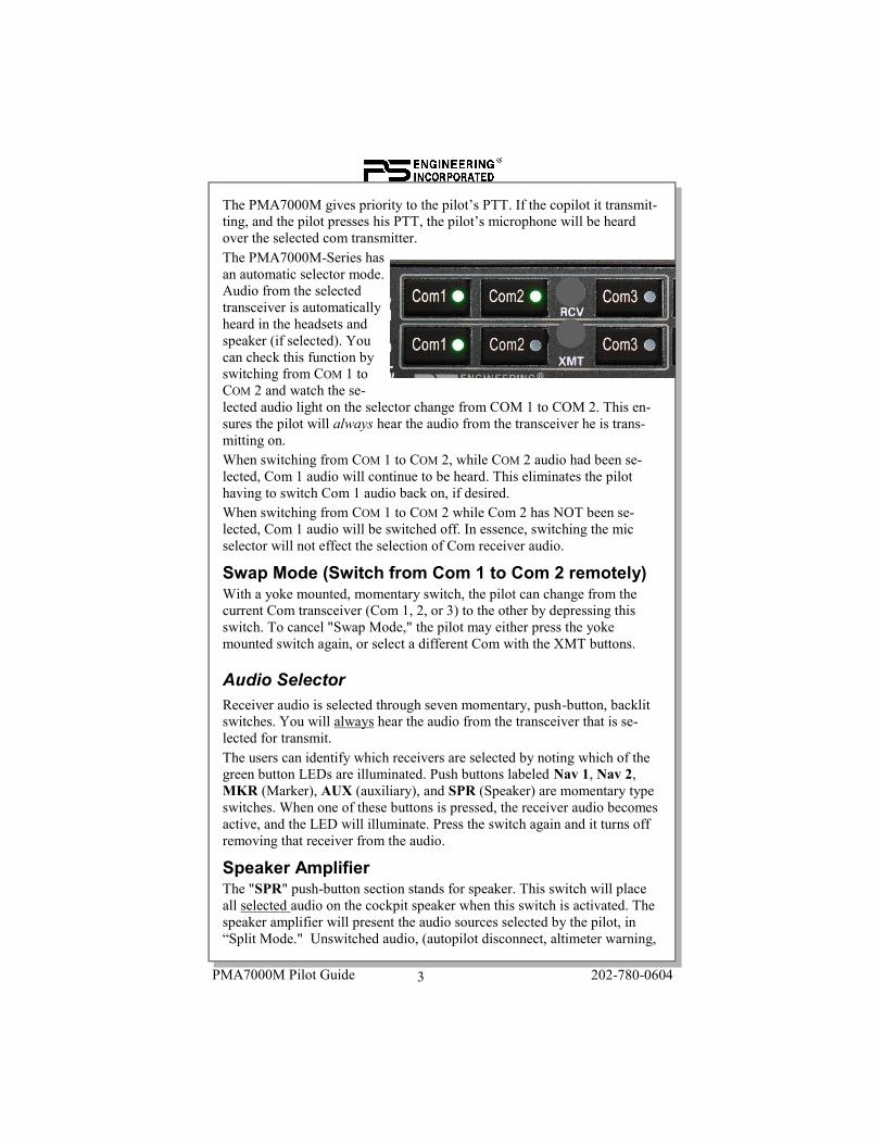
The PMA7000M gives priority to the pilot’s PTT. If the copilot it transmit-ting, and the pilot presses his PTT, the pilot’s microphone will be heardover the selected com transmitter.The PMA7000M-Series hasan automatic selector mode.Audio from the selectedtransceiver is automaticallyheard in the headsets andspeaker (if selected). Youcan check this function byswitching from COM 1 toCOM 2 and watch the se-lected audio light on the selector change from COM 1 to COM 2. This en-sures the pilot will always hear the audio from the transceiver he is trans-mitting on.When switching from COM 1 to COM 2, while COM 2 audio had been se-lected, Com 1 audio will continue to be heard. This eliminates the pilothaving to switch Com 1 audio back on, if desired.When switching from COM 1 to COM 2 while Com 2 has NOT been se-lected, Com 1 audio will be switched off. In essence, switching the micselector will not effect the selection of Com receiver audio.
Swap Mode (Switch from Com 1 to Com 2 remotely)With a yoke mounted, momentary switch, the pilot can change from thecurrent Com transceiver (Com 1, 2, or 3) to the other by depressing thisswitch. To cancel "Swap Mode," the pilot may either press the yokemounted switch again, or select a different Com with the XMT buttons.
Audio SelectorReceiver audio is selected through seven momentary, push-button, backlitswitches. You will always hear the audio from the transceiver that is se-lected for transmit.The users can identify which receivers are selected by noting which of thegreen button LEDs are illuminated. Push buttons labeled Nav 1, Nav 2,MKR (Marker), AUX (auxiliary), and SPR (Speaker) are momentary typeswitches. When one of these buttons is pressed, the receiver audio becomesactive, and the LED will illuminate. Press the switch again and it turns offremoving that receiver from the audio.
Speaker AmplifierThe "SPR" push-button section stands for speaker. This switch will placeall selected audio on the cockpit speaker when this switch is activated. Thespeaker amplifier will present the audio sources selected by the pilot, in“Split Mode." Unswitched audio, (autopilot disconnect, altimeter warning,
4 PMA7000M Pilot202-780-0604 Jan 2015
etc.) will come through the speaker regardless of the speaker button posi-tion.
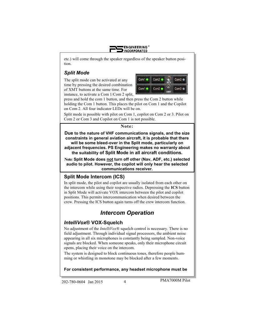
Split ModeThe split mode can be activated at anytime by pressing the desired combinationof XMT buttons at the same time. Forinstance, to activate a Com 1/Com 2 split,press and hold the com 1 button, and then press the Com 2 button whileholding the Com 1 button. This places the pilot on Com 1 and the Copiloton Com 2. All four indicator LEDs will be on.Split mode is possible with pilot on Com 1, copilot on Com 2 or 3. Pilot onCom 2 or Com 3 and Copilot on Com 1 is not possible.
Note:Due to the nature of VHF communications signals, and the sizeconstraints in general aviation aircraft, it is probable that there
will be some bleed-over in the Split mode, particularly onadjacent frequencies. PS Engineering makes no warranty about
the suitability of Split Mode in all aircraft conditions.Note: Split Mode does not turn off other (Nav, ADF, etc.) selectedaudio to pilot. However, the copilot will only hear the selected
communications receiver.
Split Mode Intercom (ICS)In split mode, the pilot and copilot are usually isolated from each other onthe intercom while using their respective radios. Depressing the ICS buttonin Split Mode will activate VOX intercom between the pilot and copilotpositions. This permits intercommunication when desired between thecrew. Pressing the ICS button again turns off the crew intercom function.
Intercom OperationIntelliVox® VOX-SquelchNo adjustment of the IntelliVox® squelch control is necessary. There is nofield adjustment. Through individual signal processors, the ambient noiseappearing in all six microphones is constantly being sampled. Non-voicesignals are blocked. When someone speaks, only their microphone circuitopens, placing their voice on the intercom.The system is designed to block continuous tones, therefore people hum-ming or whistling in monotone may be blocked after a few moments.
For consistent performance, any headset microphone must be
5PMA7000M Pilot Guide 202-780-0604
placed within ¼-inch of your lips, preferably against them. (ref:RTCA/DO-214, 1.3.1.1 (a)).It is important to keep the microphone out of a direct wind path.Moving your head through a vent air stream may cause the In-telliVox® to open momentarily. This is normal.The IntelliVox® is designed to work with normal aircraft cabinnoise levels (70 dB and above). It loves airplane noise! There-fore, it has a tendency to miss initial syllables in a quiet cabin,such as in the hangar, or without the engine running. This isnormal, for best performance, go fly!For optimum microphone performance, PS Engineering recommends in-stallation of a Microphone Muff Kit from Oregon Aero (1-800-888-6910).This will not only optimize VOX performance, but will improve the overallclarity of all your communications.
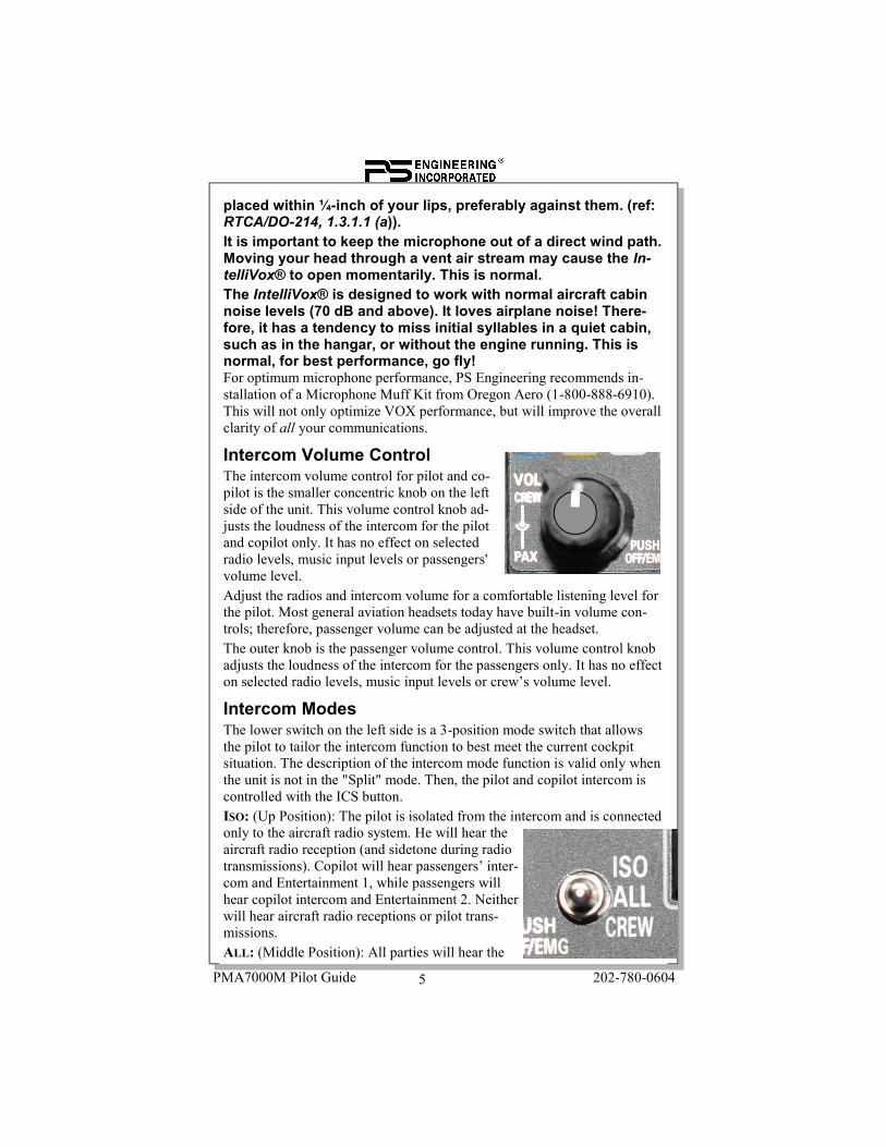
Intercom Volume ControlThe intercom volume control for pilot and co-pilot is the smaller concentric knob on the leftside of the unit. This volume control knob ad-justs the loudness of the intercom for the pilotand copilot only. It has no effect on selectedradio levels, music input levels or passengers'volume level.Adjust the radios and intercom volume for a comfortable listening level forthe pilot. Most general aviation headsets today have built-in volume con-trols; therefore, passenger volume can be adjusted at the headset.The outer knob is the passenger volume control. This volume control knobadjusts the loudness of the intercom for the passengers only. It has no effecton selected radio levels, music input levels or crew’s volume level.
Intercom ModesThe lower switch on the left side is a 3-position mode switch that allowsthe pilot to tailor the intercom function to best meet the current cockpitsituation. The description of the intercom mode function is valid only whenthe unit is not in the "Split" mode. Then, the pilot and copilot intercom iscontrolled with the ICS button.ISO: (Up Position): The pilot is isolated from the intercom and is connectedonly to the aircraft radio system. He will hear theaircraft radio reception (and sidetone during radiotransmissions). Copilot will hear passengers’ inter-com and Entertainment 1, while passengers willhear copilot intercom and Entertainment 2. Neitherwill hear aircraft radio receptions or pilot trans-missions.ALL: (Middle Position): All parties will hear the

6 PMA7000M Pilot202-780-0604 Jan 2015
aircraft radio and intercom. Crew will hear Entertainment 1, passengerswill hear Entertainment 2. During any radio or intercom communications,the music volume automatically decreases. The music volume increasesgradually back to the original level after communications have been com-pleted.CREW (Down Position): Pilot and copilot are connected on one intercomchannel and have exclusive access to the aircraft radios. They may alsolisten to Entertainment 1. Passengers can continue to communicate withthemselves without interrupting the Crew and also may listen to Entertain-ment 2.Anytime the PMA7000M is in either the Split Mode ("COM 1/COM 2, COM1/COM 3"), the pilot and copilot intercom is controlled with the ICS button.The passengers will maintain intercommunications, but never hear aircraftradios.Alternate Intercom ModeIf an external switch is installed for the purpose, the PMA7000M can enter“Alternate Intercom Mode.” When the intercom is in ALL mode, with al-ternate mode enabled the passengers will NOT hear the aircraft radios, butthey will hear the crew on the intercom. In addition, the crew microphoneswill be blocked from the crew headsets while the radio audio is active.
Entertainment InputThe audio selector panel has provisions for two separate music input de-vices. Music 1 feeds the pilot and copilot positions, music 2 feeds the pas-senger positions. They operate independently in the PMA7000M.While in the ISO (Isolate) mode, the copilot will hear Entertainment 1while the four passengers will hear Entertainment #2. In normal operation,whenever a person speaks, or if the aircraft radio becomes active, the musicwill automatically mute and then will gradually return to the original listen-ing level when the intercom or radio conversation ceases.Bluetooth® Music is presented as Music 1, and heard by the pilot and copi-lot positions. However, Bluetooth can be provided to all positions. Pressand hold the ICS button for one second, or until the Bluetooth music ap-pears in passenger headphones.It is also possible to use a single input device for both music inputs. How-ever, we suggest that a switch (DPDT) be installed between the music de-vice and music input #1. This will allow the pilot to direct the music asdesired.
Soft Mute and Soft Mute inhibitThe Soft Mute feature assures that the aircraft radio transmissions will notbe missed due to music playing. When there is radio reception or intercomconversation, the music is muted. When the radio or intercom traffic
7PMA7000M Pilot Guide 202-780-0604
ceases, the level gradually returns to normal.The front panel ICS switch controls muting ofmusic source #1 (for pilot and copilot). Pushingthis button places the ICS in Karaoke (or singalong) mode, which inhibits the soft mute fea-ture. This allows the music to continue uninter-rupted by intercom or radio traffic when cockpit workload is appropriate.Pushing the button again will release the mute inhibit function.The passenger music, source #2, can be placed in the Karaoke mode if aremote switch is installed in the aircraft.
Bluetooth Telephone ModeThe Bluetooth connection input can serve as a full duplex interface fortelephone systems if the installation is correctly configured. PS Engineer-ing does not guarantee compatibility with all Bluetooth® telephone sys-tems.
Mode Pilot Hears CopilotHears
Passen-gersHear
Telephone Comments
ISO A/C RadiosPilot Side-
tone(during
radio trans-mission)
Entertain-ment 1 is
Muted
Passen-gers
CopilotMusicInput 1
CopilotPassen-
gersMusic 2
“Phone Booth”mode
Pilot has exclu-sive use of the
telephone
This mode allows the pilot tocommunicate without the othersbeing bothered by the conversa-
tions. Copilot and passengerscan continue to communicate
and listen to music
ALL RadiosCopilotPassen-
gersMusic 1
RadiosPilot
Passen-gers
Music 1
RadiosPilot
CopilotPassen-
gersMusic 2
All have accessto phone.
This mode allows all onboard to hear radio recep-
tion as well as communicateon the intercom. Music andintercom is muted during
intercom and radio commu-nications
CREW RadiosCopilotMusic 1
RadiosPilot
Music 1
Passen-gers
Music 2
Pilot and copi-lot have phoneaccess only
This mode allows the pilotand copilot to concentrateon flying while the passen-
gers can communicateamongst themselves
8 PMA7000M Pilot202-780-0604 Jan 2015
Calls are answered or placed from the telephone itself.In the All intercom mode, everyone is on the telephone and hears selectedradio audio. The pilot and copilot will have full transmit capability on theselected transceiver Com 1 or 2, simply by using their respective PTTswitch.In CREW mode, the pilot and copilot may use the telephone. Passengerswill not hear telephone or other radios.In ISO intercom mode, the pilot position is in the "Phone Booth." He willalso have access to Com 1 or 2, and will transmit on that radio using thePTT. All selected audio is provided.
Note: Because the telephone uses an intercom circuit, all stations onthat circuit will lose intercom capability when the telephone is in use.
Pairing and unpairing Bluetooth devicesThe PMA7000M can be paired with up to eight individual devices. Whenthat number is exceeded, one device will be automatically un-paired to al-low the new device. The device eliminate will be selected at random by theBluetooth module. Hint, if your old phone is not recognized by thePMA7000M, you may need to clear the audio panel and re-pair.To reset the Bluetooth, Hold Nav 1 and Nav 2 buttons at the same time formore then 3 seconds.
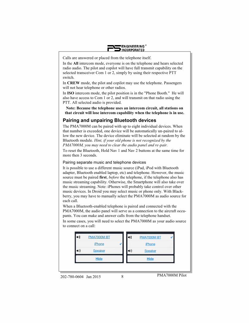
Pairing separate music and telephone devicesIt is possible to use a different music source (iPad, iPod with Bluetoothadapter, Bluetooth enabled laptop, etc) and telephone. However, the musicsource must be paired first, before the telephone, if the telephone also hasmusic streaming capability. Otherwise, the Smartphone will also take overthe music streaming. Note: iPhones will probably take control over othermusic devices. In Droid you may select music or phone only. With Black-berry, you may have to manually select the PMA7000M as audio source foreach call.When a Bluetooth-enabled telephone is paired and connected with thePMA7000M, the audio panel will serve as a connection to the aircraft occu-pants. You can make and answer calls from the telephone handset.In some cases, you will need to select the PMA7000M as your audio sourceto connect on a call:
9PMA7000M Pilot Guide 202-780-0604
Cellular telephone sidetone
As shipped from PS Engineering, the PMA7000M provides cellular tele-phone sidetone (the user’s voice fed back to the headset). Some cell phonesprovide sidetone. In PMA7000M Telephone sidetone can be enabled/disabled by a internal modification. Con-tact PS Engineering for information.
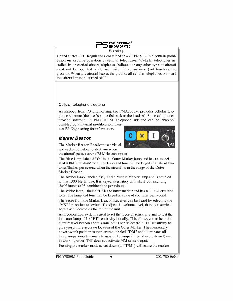
Marker BeaconThe Marker Beacon Receiver uses visualand audio indicators to alert you whenthe aircraft passes over a 75 MHz transmitter.The Blue lamp, labeled "O," is the Outer Marker lamp and has an associ-ated 400-Hertz 'dash' tone. The lamp and tone will be keyed at a rate of twotones/flashes per second when the aircraft is in the range of the OuterMarker Beacon.The Amber lamp, labeled "M," is the Middle Marker lamp and is coupledwith a 1300-Hertz tone. It is keyed alternately with short 'dot' and long'dash' bursts at 95 combinations per minute.The White lamp, labeled "I," is the Inner marker and has a 3000-Hertz 'dot'tone. The lamp and tone will be keyed at a rate of six times per second.The audio from the Marker Beacon Receiver can be heard by selecting the"MKR" push-button switch. To adjust the volume level, there is a serviceadjustment located on the top of the unit.A three-position switch is used to set the receiver sensitivity and to test theindicator lamps. Use "HI" sensitivity initially. This allows you to hear theouter marker beacon about a mile out. Then select the “LO” sensitivity togive you a more accurate location of the Outer Marker. The momentarydown switch position is marker test, labeled "T/M" and illuminates allthree lamps simultaneously to assure the lamps (internal and external) arein working order. TST does not activate MM sense output.Pressing the marker mode select down (to “T/M”) will cause the marker
Warning:United States FCC Regulations contained in 47 CFR § 22.925 contain prohi-bition on airborne operation of cellular telephones. “Cellular telephones in-stalled in or carried aboard airplanes, balloons or any other type of aircraftmust not be operated while such aircraft are airborne (not touching theground). When any aircraft leaves the ground, all cellular telephones on boardthat aircraft must be turned off.”

10 PMA7000M Pilot202-780-0604 Jan 2015
audio to mute for that beacon. The next beacon received will re-activate theaudio.

11PMA7000M Pilot Guide 202-780-0604
WarrantyIn order for the factory warranty to be valid, the installations in a certifiedaircraft must be accomplished by an FAA-(or other ICAO agency) certifiedavionics shop and authorized PS Engineering dealer. If the unit is beinginstalled by a non-certified individual in an experimental aircraft, a factory-made intercom harness must be used for the warranty to be valid.PS Engineering, Inc. warrants this product to be free from defect in mate-rial and workmanship for a period of two (2) years from the date of sale.During the first twelve (12) months of the warranty period, PS En-gineering, Inc., at its option, will send a replacement unit at our ex-pense if the unit should be determined to be defective after consulta-tion with a factory technician.For the remaining twelve (12) months of the PMA7000-series three-year warranty period, PS Engineering, Inc., at its option, will send areplacement unit at the customer’s expense if the unit should be de-termined to be defective after consultation with a factory technician.All transportation charges for returning the defective units are the responsi-bility of the purchaser. All domestic transportation charges for returning theexchange or repaired unit to the purchaser will be borne by PS Engineering,Inc. The risk of loss or damage to the product is borne by the party makingthe shipment, unless the purchaser requests a specific method of shipment.In this case, the purchaser assumes the risk of loss.This warranty is not transferable. Any implied warranties expire at the ex-piration date of this warranty. PS Engineering SHALL NOT BE LIABLEFOR INCIDENTAL OR CONSEQUENTIAL DAMAGES. This warrantydoes not cover a defect that has resulted from improper handling, storage orpreservation, or unreasonable use or maintenance as determined by us. Thiswarranty is void if there is any attempt to dissemble this product withoutfactory authorization. This warranty gives you specific legal rights, and youmay also have other rights, which may vary from state to state. Some statesdo not allow the exclusion of limitation of incidental or consequential dam-ages, so the above limitation or exclusions may not apply to you.All items repaired or replaced under this warranty are warranted for theremainder of the original warranty period. PS Engineering, Inc. reserves therights to make modifications or improvements to the product without obli-gation to perform like modifications or improvements to previously manu-factured products.
Factory ServiceCall PS Engineering, Inc. at (865) 988-9800 before you return any unit.
12 PMA7000M Pilot202-780-0604 Jan 2015
This will allow the service technician to provide any other suggestions foridentifying the problem and recommend possible solutions.After discussing the problem with the technician and you obtain a ReturnAuthorization Number, ship product to:PS Engineering, Inc.Attn: Service Department9800 Martel RdLenoir City, TN 37772(865) 988-9800 FAX (865) 988-6619Email: [email protected]
NOTE: PS Engineering will not be responsible for any product returned tous by US Mail, or in other than the original or UPS approved equivalentpackaging. Units without an RMA or detailed description of problem ANDa contact phone number will be refused.
PS Engineering, Inc. 2015 ©Copyright Notice
Copyrighted information in this manual is subject to change without notice. PS Engineeringreserves the right to improve or change the products or contents of this manual, withoutnotification of any person or agency. The contents of this pilot’s guide may be downloaded,stored and reprinted for personal use provided that this copyright information is included.Commercial use is strictly prohibited. For further information contact the Publications Man-ager at PS Engineering, Inc., 9800 Martel Road, Lenoir City, TN 37772. Phone (865) 988-9800
Record
PMA7000M Serial Number: _________________
Date of Purchase:__________________________
Installed by: ______________________________